WO2023214529A1 - 心腔内除細動システム - Google Patents
心腔内除細動システム Download PDFInfo
- Publication number
- WO2023214529A1 WO2023214529A1 PCT/JP2023/016506 JP2023016506W WO2023214529A1 WO 2023214529 A1 WO2023214529 A1 WO 2023214529A1 JP 2023016506 W JP2023016506 W JP 2023016506W WO 2023214529 A1 WO2023214529 A1 WO 2023214529A1
- Authority
- WO
- WIPO (PCT)
- Prior art keywords
- defibrillation
- electrode group
- electrodes
- intracardiac
- catheter
- Prior art date
- Legal status (The legal status is an assumption and is not a legal conclusion. Google has not performed a legal analysis and makes no representation as to the accuracy of the status listed.)
- Ceased
Links
Images


Classifications
-
- A—HUMAN NECESSITIES
- A61—MEDICAL OR VETERINARY SCIENCE; HYGIENE
- A61B—DIAGNOSIS; SURGERY; IDENTIFICATION
- A61B5/00—Measuring for diagnostic purposes; Identification of persons
- A61B5/24—Detecting, measuring or recording bioelectric or biomagnetic signals of the body or parts thereof
- A61B5/25—Bioelectric electrodes therefor
- A61B5/279—Bioelectric electrodes therefor specially adapted for particular uses
- A61B5/28—Bioelectric electrodes therefor specially adapted for particular uses for electrocardiography [ECG]
- A61B5/283—Invasive
- A61B5/287—Holders for multiple electrodes, e.g. electrode catheters for electrophysiological study [EPS]
-
- A—HUMAN NECESSITIES
- A61—MEDICAL OR VETERINARY SCIENCE; HYGIENE
- A61B—DIAGNOSIS; SURGERY; IDENTIFICATION
- A61B5/00—Measuring for diagnostic purposes; Identification of persons
- A61B5/24—Detecting, measuring or recording bioelectric or biomagnetic signals of the body or parts thereof
- A61B5/30—Input circuits therefor
- A61B5/304—Switching circuits
-
- A—HUMAN NECESSITIES
- A61—MEDICAL OR VETERINARY SCIENCE; HYGIENE
- A61B—DIAGNOSIS; SURGERY; IDENTIFICATION
- A61B5/00—Measuring for diagnostic purposes; Identification of persons
- A61B5/24—Detecting, measuring or recording bioelectric or biomagnetic signals of the body or parts thereof
- A61B5/316—Modalities, i.e. specific diagnostic methods
- A61B5/318—Heart-related electrical modalities, e.g. electrocardiography [ECG]
- A61B5/33—Heart-related electrical modalities, e.g. electrocardiography [ECG] specially adapted for cooperation with other devices
-
- A—HUMAN NECESSITIES
- A61—MEDICAL OR VETERINARY SCIENCE; HYGIENE
- A61M—DEVICES FOR INTRODUCING MEDIA INTO, OR ONTO, THE BODY; DEVICES FOR TRANSDUCING BODY MEDIA OR FOR TAKING MEDIA FROM THE BODY; DEVICES FOR PRODUCING OR ENDING SLEEP OR STUPOR
- A61M25/00—Catheters; Hollow probes
- A61M25/10—Balloon catheters
-
- A—HUMAN NECESSITIES
- A61—MEDICAL OR VETERINARY SCIENCE; HYGIENE
- A61N—ELECTROTHERAPY; MAGNETOTHERAPY; RADIATION THERAPY; ULTRASOUND THERAPY
- A61N1/00—Electrotherapy; Circuits therefor
- A61N1/18—Applying electric currents by contact electrodes
- A61N1/32—Applying electric currents by contact electrodes alternating or intermittent currents
- A61N1/38—Applying electric currents by contact electrodes alternating or intermittent currents for producing shock effects
- A61N1/39—Heart defibrillators
Definitions
- the present disclosure relates to intracardiac defibrillation systems.
- Patent Document 1 discloses an intracardiac defibrillation catheter that includes a defibrillation catheter that is inserted into a cardiac chamber to perform defibrillation, and a power supply device that applies a DC voltage to an electrode of the defibrillation catheter. The system is described.
- the above-mentioned defibrillation catheter includes a first electrode group consisting of a plurality of ring-shaped electrodes for applying voltage of the same polarity, and a plurality of ring-shaped electrodes for applying a voltage of opposite polarity to the first electrode group. and a second electrode group consisting of electrodes.
- the first electrode group and the second electrode group are mounted on the outer periphery of the same tube member at a distance from each other. Therefore, since the distance between the first electrode group and the second electrode group on the tube member is constant, it is difficult to indwell the first electrode group and the second electrode group at desired positions within the heart chamber. be. Therefore, it may not be possible to place the first electrode group and the second electrode group at appropriate positions for the location where the myocardium is spasming. In such a case, defibrillation energy needs to be set high in order to electrically reset the convulsing area, which may reduce defibrillation efficiency.
- the present disclosure provides an intracardiac defibrillation system that can improve defibrillation efficiency.
- An intracardiac defibrillation system is an intracardiac defibrillation system that performs electrical cardioversion during surgery.
- This intracardiac defibrillation system includes a first defibrillation catheter for performing defibrillation within a cardiac cavity, the first defibrillation catheter having a first electrode group including a plurality of first electrodes.
- a second defibrillation catheter for performing defibrillation within a heart chamber, the second defibrillation catheter having a second electrode group including a plurality of second electrodes; and a first defibrillation catheter.
- a defibrillation device includes a first connector for connecting a defibrillation catheter, a second connector for connecting a second defibrillation catheter, and a power supply circuit for supplying voltage.
- a defibrillator applies a voltage of the same polarity to a plurality of first electrodes, and a voltage of the same polarity to a plurality of second electrodes.
- the first defibrillation catheter has a first electrode group
- the second defibrillation catheter has a second electrode group.
- the first electrode group and the second electrode group are included in different defibrillation catheters, the degree of freedom in indwelling the first electrode group and the second electrode group is improved. Therefore, the first electrode group and the second electrode group can be placed in positions close to the location where the myocardium is undergoing spasm. Thereby, defibrillation energy can be efficiently applied to the location where the myocardium is undergoing convulsion. As a result, it is not necessary to set defibrillation energy higher than necessary, so it is possible to improve defibrillation efficiency.
- the defibrillator may apply a voltage having a polarity different from the polarity of the voltage applied to the plurality of first electrodes to the plurality of second electrodes. According to this configuration, defibrillation energy can be applied between the first electrode group and the second electrode group.
- the intracardiac defibrillation system further includes an electrocardiograph and a switching circuit that selectively switches between a connection destination of the first electrode group and a connection destination of the second electrode group. It's okay.
- the switching circuit may be capable of selectively switching between a state in which the first electrode group is connected to a power supply circuit and a state in which the first electrode group is connected to an electrocardiograph.
- the switching circuit may be capable of selectively switching between a state where the second electrode group is connected to the power supply circuit and a state where the second electrode group is connected to the electrocardiograph.
- the electrocardiograph may measure the potentials of a plurality of first electrodes and the potentials of a plurality of second electrodes. According to this configuration, intracardiac potential can be measured without using an electrophysiological testing catheter.
- the intracardiac defibrillation system may further include an electrocardiograph.
- the first defibrillation catheter may further include a third electrode group including a plurality of third electrodes.
- the second defibrillation catheter may further include a fourth electrode group including a plurality of fourth electrodes.
- the electrocardiograph may measure the potentials of the plurality of third electrodes and the potentials of the plurality of fourth electrodes. According to this configuration, intracardiac potential can be measured without using an electrophysiological testing catheter.
- the intracardiac defibrillation system may further include a return electrode for performing defibrillation on the body surface.
- the defibrillator may further include a third connector for connecting a return electrode.
- the defibrillator may apply a voltage having a polarity different from the polarity of the voltage applied to the plurality of first electrodes or the plurality of second electrodes to the return electrode. According to this configuration, defibrillation energy can be applied between the first electrode group or the second electrode group and the return electrode.
- the defibrillator includes a first member of the first electrode group, the second electrode group, and the return electrode plate that is connected to the first terminal of the power supply circuit, and a second terminal of the power supply circuit. It may further include a switching circuit capable of selectively switching between the second member connected to the second member and the second member connected to the second member.
- defibrillation can be performed using a combination selected from the first electrode group, the second electrode group, and the return electrode. Therefore, since an appropriate combination can be selected depending on the location where fibrillation has occurred, defibrillation efficiency can be improved.
- the defibrillator may further include a measuring device that measures the resistance of the path to which the voltage is supplied.
- the switching circuit may selectively connect the first member and the second member to either the power supply circuit or the measuring device. According to this configuration, a combination selected from the first electrode group, the second electrode group, and the return electrode plate is selectively connected to the power supply circuit and the measuring device. Therefore, compared to a configuration in which a path for supplying voltage and a path for measuring resistance value are provided separately, the defibrillator can be made smaller.
- the defibrillator may further include a measuring device that measures the resistance value of the path to which the voltage is supplied, and an arithmetic processing unit that controls the power supply circuit.
- the arithmetic processing unit may apply a voltage to the power supply circuit when the resistance value is within an appropriate range. If the resistance value of the path to which the voltage is supplied is outside the appropriate range, it is considered that the electrode to which the voltage is applied is not properly placed. In order to perform defibrillation in this state, it is necessary to increase the defibrillation energy. According to the above configuration, the voltage is applied when the resistance value of the path to which the voltage is supplied is within an appropriate range, so there is no need to increase the defibrillation energy excessively. As a result, defibrillation efficiency can be improved.
- the arithmetic processing unit may apply a voltage to the power supply circuit in synchronization with the peak of the intracardiac potential. With this configuration, the voltage is applied in synchronization with the peak of the intracardiac potential, so that induction of ventricular fibrillation can be prevented.
- the first defibrillation catheter may further include a tubular member.
- Each of the plurality of first electrodes may be provided on the outer peripheral surface of the tubular member, and the plurality of first electrodes may be arranged in the axial direction of the tubular member. According to this configuration, the flexibility and pliability of the first defibrillation catheter can be increased compared to a configuration in which a plurality of first electrodes are integrated. Therefore, it becomes possible to improve the operability of the first defibrillation catheter.
- the first defibrillation catheter may further include a leaf spring for changing the planar tip of the tubular member. According to this configuration, the tip of the tubular member can be deflected using the leaf spring. As a result, it becomes possible to improve the operability of the first defibrillation catheter.
- the first defibrillation catheter may further include a lead wire group including a plurality of lead wires and a lumen tube within which the lead wire group extends.
- a lumen tube may be disposed within the tubular member.
- the plurality of lead wires may electrically connect the plurality of first electrodes and the first connector. According to this configuration, since the lead wire group extends inside the lumen tube, the lead wire group can be electrically isolated from other members arranged within the tubular member.
- the first defibrillation catheter includes a distal tip disposed at a distal end of the tubular member, and a distal tip disposed within the tubular member and eccentric to the central axis of the tubular member.
- the device may further include a pull wire having one end that is fixed, and an operation unit that moves the pull wire forward and backward in the axial direction.
- one end of the pull wire is fixed to the distal tip at a position eccentric to the central axis of the tubular member, so by moving the pull wire back and forth using the operating section, the distal tip is fixed to the distal tip at a position eccentric to the central axis of the tubular member. Force is applied at the position. This allows the tip of the tubular member to be deflected. As a result, it becomes possible to improve the operability of the first defibrillation catheter.
- the first defibrillation catheter may further include a lumen tube within which the pull wire extends.
- the lumen tube may be disposed within the tubular member.
- the first defibrillation catheter may further include a balloon disposed at the distal end of the tubular member and capable of being inflated and deflated, and a supply tube for supplying fluid to the balloon. good.
- a balloon disposed at the distal end of the tubular member and capable of being inflated and deflated
- a supply tube for supplying fluid to the balloon. good.
- the first defibrillation catheter is a passage tube for passing a guidewire, the passage tube being disposed within the tubular member and extending from the proximal end of the tubular member to the distal end of the tubular member. You may further have. According to this configuration, the first defibrillation catheter can be advanced along the guide wire with the guide wire inserted into the blood vessel. Therefore, the insertion work of the first defibrillation catheter can be simplified.
- the first defibrillation catheter further includes an insertion tube for passing the guidewire, the insertion tube being disposed within the tubular member and extending from the outer circumferential surface to the distal end of the tubular member. You may. According to this configuration, the first defibrillation catheter can be advanced along the guide wire with the guide wire inserted into the blood vessel. Therefore, the insertion work of the first defibrillation catheter can be simplified.
- each of the plurality of first electrodes may have a convex curved shape in a direction intersecting the axial direction.
- the greater the length of the first electrode in the axial direction the less flexible and pliable the first defibrillation catheter becomes, impairing the maneuverability of the first defibrillation catheter.
- the smaller the contact area between the first electrode and the surrounding tissue the higher the current density when a voltage is applied to the first electrode, and the higher the possibility of damaging the surrounding tissue.
- the surface area of the first electrode can be increased without increasing the length in the axial direction. Therefore, the possibility of damaging surrounding tissues can be reduced without impairing the operability of the first defibrillation catheter.
- the first defibrillation catheter includes an insulating member that fills a recess defined by an axial end surface and an outer peripheral surface of one of the plurality of first electrodes. You may further have it.
- a recess is formed between the end surface of the first electrode in the axial direction and the outer peripheral surface of the tubular member, when a voltage is applied to the first electrode, the current density increases at the periphery of the end surface.
- the recess is filled with the insulating member, it is possible to suppress an increase in the current density at the periphery of the end face when a voltage is applied to the first electrode. Therefore, the possibility of damaging surrounding tissues can be reduced.
- FIG. 1 is a schematic configuration diagram of an intracardiac defibrillation system according to one embodiment.
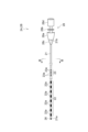
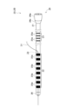
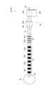
- FIG. 2 is a schematic diagram of the defibrillation catheter shown in FIG. 1.
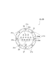
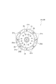
- FIG. 3 is a sectional view taken along line III-III in FIG. 2.
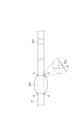
- FIG. 4 is an enlarged view of the electrode shown in FIG. 2.
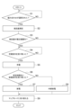
- FIG. 5 is a flowchart showing a series of processes of a defibrillation method performed by the defibrillation apparatus shown in FIG.
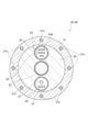
- FIG. 6 is a diagram showing an example of the connection state of the switching circuit in map mode.
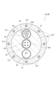
- FIG. 7 is a diagram illustrating an example of the connection state of the switching circuit during resistance value measurement in intracardiac defibrillation mode.
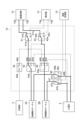
- FIG. 1 is a schematic configuration diagram of an intracardiac defibrillation system according to one embodiment.
- FIG. 2 is a schematic diagram of the defibrillation catheter shown in FIG. 1.
- FIG. 3 is a
- FIG. 8 is a diagram showing another example of the connection state of the switching circuit when measuring the resistance value in the intracardiac defibrillation mode.
- FIG. 9 is a diagram showing still another example of the connection state of the switching circuit during resistance value measurement in the intracardiac defibrillation mode.
- FIG. 10 is a diagram showing still another example of the connection state of the switching circuit when measuring the resistance value in the intracardiac defibrillation mode.
- FIG. 11 is a diagram showing the waveform of the voltage applied by the power supply circuit shown in FIG. 1.
- FIG. 12 is a diagram showing an example of the connection state of the switching circuit when voltage is applied in intracardiac defibrillation mode.
- FIG. 13 is a diagram showing another example of the connection state of the switching circuit when voltage is applied in the intracardiac defibrillation mode.
- FIG. 14 is a diagram showing still another example of the connection state of the switching circuit when voltage is applied in the intracardiac defibrillation mode.
- FIG. 15 is a diagram showing still another example of the connection state of the switching circuit when voltage is applied in the intracardiac defibrillation mode.
- FIG. 16 is a schematic configuration diagram of a modified defibrillation catheter.
- FIG. 17 is a cross-sectional view taken along line XVII-XVII in FIG. 16.
- FIG. 18 is a schematic configuration diagram of another modified example of a defibrillation catheter.
- FIG. 18 is a schematic configuration diagram of another modified example of a defibrillation catheter.
- FIG. 19 is a schematic configuration diagram of yet another modified example of a defibrillation catheter.
- FIG. 20 is a sectional view of yet another modified example of a defibrillation catheter.
- FIG. 21 is a cross-sectional view of the defibrillation catheter shown in FIG. 20 at another location.
- FIG. 1 is a schematic configuration diagram of an intracardiac defibrillation system according to one embodiment.
- FIG. 2 is a schematic diagram of the defibrillation catheter shown in FIG. 1.
- FIG. 3 is a sectional view taken along line III-III in FIG. 2.
- FIG. 4 is an enlarged view of the electrode shown in FIG. 2.
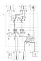
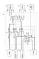
- the intracardiac defibrillation system 1 shown in FIG. 1 is a system for performing electrical cardioversion during surgery. Defibrillation is the process of restoring a fibrillating heart to normal. Fibrillation refers to a condition in which the heart muscle spasms. Fibrillation includes, for example, atrial fibrillation and ventricular fibrillation.
- the intracardiac defibrillation system 1 performs defibrillation by electrically resetting the location where the myocardium is convulsing.
- the intracardiac defibrillation system 1 is used, for example, to treat atrial fibrillation by catheter ablation.
- the intracardiac defibrillation system 1 includes a defibrillation catheter 2A (first defibrillation catheter), a defibrillation catheter 2B (second defibrillation catheter), a return electrode 3, and an electrocardiograph 4. , a defibrillator 10.
- each of the defibrillation catheters 2A and 2B is devices used to perform defibrillation within the heart chamber of the patient P. As shown in FIGS. 2 and 3, each of the defibrillation catheters 2A and 2B includes a tube 21 (tubular member), an electrode group 22, an electrode group 23, a lead wire group 24, and a lead wire group 25. , a distal tip 26 , a pull wire 27 , and a handle 28 .
- the tube 21 is a long tubular member.
- the tube 21 is made of, for example, a high hardness nylon elastomer.
- An example of a nylon elastomer is PEBAX®.
- the tubes 21 may have different hardnesses in the axial direction of the tubes 21.
- the tube 21 is configured such that the hardness increases in stages from the distal end 21a to the proximal end 21b of the tube 21.
- the hardness of the tube 21 (hardness measured by a D-type hardness meter) is, for example, 40 to 75.
- the outer diameter of the tube 21 is, for example, 1.2 mm to 2.4 mm.
- the tube 21 includes a blade 21c.
- the blade 21c is a member that reinforces the tube 21.
- the braid 21c is a braided wire made of a metal material.
- the blade 21c is made of, for example, stainless steel wire.
- the blade 21c is provided over the entire circumference of the tube 21 from the base end of the tube 21 to this side of the electrode group 22. The blade 21c is not provided in the region of the tube 21 where the electrode group 22 is provided.
- the electrode group 22 includes a plurality of electrodes 22a.
- Each electrode 22a is a member for applying defibrillation energy to a desired position within the heart chamber.
- Each electrode 22a is provided on the outer peripheral surface of the tube 21.
- each electrode 22a is provided on the outer peripheral surface of the tube 21 so as to surround the tube 21 around the axis (center axis) of the tube 21.
- Each electrode 22a has a cylindrical shape with both ends open. As shown in FIG. 4, in this embodiment, each electrode 22a has an olive shape. In other words, each electrode 22a has a curved shape that is convex in a direction intersecting the axial direction of the tube 21.
- each electrode 22a has the largest outer diameter at the center of the electrode 22a in the axial direction of the tube 21, and the outer diameter gradually increases from the center toward both ends of the electrode 22a in the axial direction of the tube 21. It has a streamlined shape that becomes smaller.
- the defibrillation catheters 2A, 2B further include a glue G (insulating member) provided to fill the recess 22s.
- the glue G smoothly connects the outer circumferential surface of the electrode 22a and the outer circumferential surface of the tube 21 so that no edge is formed between the outer circumferential surface of the electrode 22a and the outer circumferential surface of the tube 21.
- each electrode 22a in the axial direction of the tube 21 is too short, the current density during voltage application may become excessive. If the length of each electrode 22a in the axial direction of the tube 21 is too long, the flexibility and pliability of the portion of the tube 21 where the electrode group 22 is provided may be impaired. From these viewpoints, the length of each electrode 22a in the axial direction of the tube 21 is, for example, 4 mm.
- Each electrode 22a may be made of a platinum-based alloy such as a platinum-iridium alloy from the viewpoint of improving contrast performance (X-ray opacity) for X-rays.
- the plurality of electrodes 22a are arranged in the axial direction of the tube 21.
- the plurality of electrodes 22a are provided at the tip of the tube 21 and arranged at equal intervals in the axial direction of the tube 21.
- the distance between two adjacent electrodes 22a is approximately 1 to 5 mm.
- the number of electrodes 22a included in the electrode group 22 may be determined depending on the length and arrangement interval of the electrodes 22a in the axial direction of the tube 21, and is, for example, about 6 to 16.
- the electrode group 22 includes eight electrodes 22a.
- Each electrode 22a is electrically connected to the defibrillator 10 by a lead wire 24a, which will be described later. Voltages of the same polarity are applied to the plurality of electrodes 22a (first electrodes) of the electrode group 22 (first electrode group) included in the defibrillation catheter 2A. Voltages of the same polarity are applied to the plurality of electrodes 22a (second electrodes) of the electrode group 22 (second electrode group) included in the defibrillation catheter 2B.
- a voltage of a polarity different from that of the voltage applied to the plurality of electrodes 22a included in the defibrillation catheter 2A may be applied to the plurality of electrodes 22a included in the defibrillation catheter 2B, or a voltage of the same polarity may be applied to the plurality of electrodes 22a included in the defibrillation catheter 2B.
- a voltage may be applied.
- the electrode groups 22 of the defibrillation catheters 2A, 2B are arranged on the right atrium side wall, the right atrium rear wall, the right atrium front wall, for example.
- the electrode group 23 includes a plurality of electrodes 23a.
- Each electrode 23a is a member for measuring intracardiac potential.
- Each electrode 23a is provided on the outer peripheral surface of the tube 21. Specifically, each electrode 23a is provided on the outer peripheral surface of the tube 21 so as to surround the tube 21 around the axis of the tube 21.
- Each electrode 23a has a cylindrical shape with both ends open. As shown in FIG. 4, in this embodiment, each electrode 23a has a cylindrical shape with a substantially uniform outer diameter over the entire length of the electrode 23a in the axial direction of the tube 21.
- the length of each electrode 23a in the axial direction of the tube 21 is, for example, 0.5 mm to 2.0 mm.
- Each electrode 23a may be made of a platinum-based alloy such as a platinum-iridium alloy from the viewpoint of improving the contrast property for X-rays.
- the plurality of electrodes 23a are arranged in the axial direction of the tube 21.
- the plurality of electrodes 23a are provided in the tube 21 at positions spaced apart from the electrode group 22 toward the base end 21b, and are arranged at equal intervals in the axial direction of the tube 21.
- the number of electrodes 23a included in the electrode group 23 may be determined depending on the length and arrangement interval of the electrodes 23a, and is, for example, about 1 to 8.
- the electrode group 23 includes four electrodes 23a. Note that no voltage for defibrillation is applied to the plurality of electrodes 23a.
- the lead wire group 24 includes a plurality of lead wires 24a.
- Each lead wire 24a is a member for electrically connecting the electrode 22a to the defibrillator 10.
- the plurality of lead wires 24a are connected to different electrodes 22a, respectively.
- the number of lead wires 24a included in the lead wire group 24 is the same as the number of electrodes 22a included in the electrode group 22.
- Each lead wire 24a is inserted through the tube 21, one end of the lead wire 24a is connected to the electrode 22a, and the other end of the lead wire 24a is connected to the connector 28d of the handle 28.
- one end of the lead wire 24a is welded to the inner peripheral surface of the electrode 22a, and the lead wire 24a is inserted into the tube 21 through a through hole provided in the tube wall of the tube 21, and is connected to the connector. It extends to 28d.
- Each lead wire 24a is a resin-coated wire that includes a metal conductor wire and a coating resin that covers the outer peripheral surface of the metal conductor wire.
- coating resins include polyimide resins, polyamide resins, and polyamideimide resins.
- the thickness of the coating resin is, for example, about 10 ⁇ m to 50 ⁇ m.
- the lead wire group 25 includes a plurality of lead wires 25a.
- Each lead wire 25a is a member for electrically connecting the electrode 23a to the defibrillator 10.
- the plurality of lead wires 25a are connected to different electrodes 23a, respectively.
- the number of lead wires 25a included in the lead wire group 25 is the same as the number of electrodes 23a included in the electrode group 23.
- Each lead wire 25a is inserted through the tube 21, one end of the lead wire 25a is connected to the electrode 23a, and the other end of the lead wire 25a is connected to the connector 28d of the handle 28.
- one end of the lead wire 25a is welded to the inner peripheral surface of the electrode 23a, and the lead wire 25a is inserted into the tube 21 through a through hole provided in the tube wall of the tube 21, and is connected to the connector. It extends to 28d.
- Each lead wire 25a is a resin-coated wire that includes a metal conductor wire and a coating resin that covers the outer peripheral surface of the metal conductor wire.
- coating resins include polyimide resins, polyamide resins, and polyamideimide resins.
- the thickness of the coating resin is, for example, about 10 ⁇ m to 50 ⁇ m.
- the tip 26 is a member for sealing the tip 21a of the tube 21.
- the distal tip 26 is attached to the distal end 21a of the tube 21.
- the tip of the tip 26 has a hemispherical shape.
- the length of the distal tip 26 in the axial direction of the tube 21 is, for example, 0.5 mm to 2.0 mm.
- one end of a pull wire 27 is fixed to (the inner surface of) the distal tip 26.
- the distal tip 26 is made of, for example, a metal material.
- the distal tip 26 may be made of platinum, platinum alloy, tungsten, tungsten alloy, silver, or silver alloy from the viewpoint of improving the contrast property for X-rays.
- the distal tip 26 may be made of resin.
- a resin having a certain degree of flexibility may be used. Examples of such resins include polyolefins such as polyethylene, polypropylene, ethylene-propylene copolymers, and ethylene-vinyl acetate copolymers, thermoplastics such as flexible polyvinyl chloride, polyamides, polyamide elastomers, and polyurethanes, silicone rubbers, and latex rubber.
- the pull wire 27 is a member for deflecting the tip of the tube 21.
- the pull wire 27 is inserted through the tube 21 and is positioned eccentrically with respect to the central axis of the tube 21 .
- One end of the pull wire 27 is fixed to the distal tip 26 at a position eccentric to the central axis of the tube 21 .
- One end of the pull wire 27 is fixed to the tip 26 by, for example, solder.
- a large diameter portion may be provided at one end of the pull wire 27 to prevent it from coming off. With this configuration, the distal tip 26 and one end of the pull wire 27 can be firmly connected, so that the distal tip 26 is prevented from falling off.
- the other end of the pull wire 27 is connected to an operating lever 28b (operating section) of the handle 28.
- the pull wire 27 is made of, for example, a metal material. Examples of metal materials include stainless steel and nickel-titanium superelastic alloys.
- the pull wire 27 does not need to be made of a metal material, and may be made of, for example, a high-strength non-conductive wire.
- the defibrillation catheters 2A, 2B may include a plurality of pull wires 27.
- the two pull wires 27 are provided symmetrically with respect to the central axis of the tube 21, the tip of the tube 21 can be deflected in two directions.
- the handle 28 is used to operate the defibrillation catheters 2A, 2B.
- the handle 28 is provided at the proximal end 21b of the tube 21.
- the handle 28 includes a main body 28a, an operating lever 28b, a strain relief 28c, and a connector 28d.
- the main body portion 28a is a portion that is held by a user who operates the defibrillation catheters 2A, 2B.
- the main body portion 28a is connected to the proximal end 21b of the tube 21.
- the main body part 28a is a cylindrical member, and a lead wire 24a, a lead wire 25a, and a pull wire 27 extending from the tube 21 are inserted into the main body part 28a while being electrically insulated from each other.
- the operating lever 28b is a member for moving the pull wire 27 forward and backward in the axial direction of the tube 21.
- the operating lever 28b may be of a rotary type or a sliding type.
- the pull wire 27 is pulled, thereby deflecting the tip of the tube 21.
- the deflection shape of the distal end of the tube 21 is equivalent to that of an ordinary electrophysiological examination catheter already on the market.
- the strain relief 28c is a member for reinforcing the connection between the tube 21 and the main body 28a.
- the strain relief 28c is provided so as to cover the connecting portion around the axis of the tube 21, and has a conical shape that tapers toward the tip 21a of the tube 21.
- the connector 28d is a member located at the end of the plurality of lead wires 24a and the plurality of lead wires 25a. Each lead wire 24a and each lead wire 25a are connected to a connector pin of a connector 28d.
- a connector 28d of the defibrillation catheter 2A is connected to a connector 10a (first connector) of the defibrillation device 10, which will be described later, via a cable.
- a connector 28d of the defibrillation catheter 2B is connected to a connector 10b (second connector) of the defibrillation device 10, which will be described later, via a cable.
- the return electrode plate 3 is a device (electrode) used to perform defibrillation on the body surface of the patient P.
- the return electrode plate 3 is attached to the body surface and applies defibrillation energy from the body surface.
- the counter electrode plate 3 is, for example, a conductive type counter electrode plate.
- the return electrode plate 3 is a plate material having a rectangular shape.
- the return electrode plate 3 is attached to the body surface, for example, so that the long sides of the return electrode plate 3 face the defibrillation catheters 2A, 2B.
- the counter electrode plate 3 may be a circular plate material.
- a voltage with a polarity different from the polarity of the voltage applied to the plurality of electrodes 22a of at least one of the defibrillation catheters 2A, 2B is applied to the return electrode plate 3.
- the electrocardiograph 4 is a device that measures the intracardiac potential of the patient P.
- the electrocardiograph 4 monitors the potential of a plurality of electrodes 23a (third electrode) of the electrode group 23 (third electrode group) included in the defibrillation catheter 2A and the potential of the electrode group 23 (fourth electrode group) included in the defibrillation catheter 2B.
- the potential of the plurality of electrodes 23a (fourth electrode) of the electrode group) is measured.
- the electrocardiograph 4 may measure the potential of the plurality of electrodes 22a of the electrode group 22 included in the defibrillation catheters 2A, 2B when no voltage is applied to these electrodes 22a.
- the electrocardiograph 4 outputs intracardiac potential to the defibrillator 10.
- the defibrillator 10 is a device that supplies defibrillation energy to perform defibrillation. Defibrillator 10 is sometimes referred to as a console.
- the defibrillation device 10 includes one or more members selected from three members: an electrode group 22 included in the defibrillation catheter 2A, an electrode group 22 included in the defibrillation catheter 2B, and a return electrode plate 3. , and one or more of the remaining members to supply defibrillating energy between the members by applying voltages of mutually different polarities to one or more of the remaining members.
- the defibrillation device 10 applies voltages of the same polarity to the plurality of electrodes 22a included in the electrode group 22 of the defibrillation catheter 2A, and applies voltages of the same polarity to the plurality of electrodes 22a included in the electrode group 22 of the defibrillation catheter 2B. Apply polar voltage.
- the defibrillation device 10 performs defibrillation by applying a voltage of a polarity different from the polarity of the voltage applied to the electrode group 22 of the defibrillation catheter 2A to the electrode group 22 of the defibrillation catheter 2B.
- Defibrillation energy is supplied between the electrode group 22 of the catheter 2A and the electrode group 22 of the defibrillation catheter 2B.
- the defibrillator 10 applies a voltage having a polarity different from the polarity of the voltage applied to the electrode group 22 of the defibrillation catheter 2A to the return electrode plate 3, thereby forming a counter electrode to the electrode group 22 of the defibrillation catheter 2A.
- Defibrillation energy is supplied between the plate 3 and the plate 3.
- the defibrillator 10 does not apply voltage to the plurality of electrodes 23a included in the electrode group 23.
- the defibrillator 10 includes a connector 10a, a connector 10b, a connector 10c (third connector), a connector 10d, a connector 10e, a connector 10f, and a connector 10g.
- the connector 10a is a connector for connecting the defibrillation catheter 2A.
- Connector 10a is connected to connector 28d of defibrillation catheter 2A by a cable.
- Connector 10b is a connector for connecting defibrillation catheter 2B.
- Connector 10b is connected to connector 28d of defibrillation catheter 2B by a cable.
- the connectors 10a and 10b may be divided into a connector for connecting the electrode group 22 and a connector for connecting the electrode group 23.
- the connector 10c is a connector for connecting the return electrode plate 3.
- the connector 10c is connected to the return electrode plate 3 by a cable.
- the connector 10d, the connector 10e, and the connector 10f are connectors for connecting the electrocardiograph 4.
- the intracardiac potential measured by the defibrillation catheter 2A is output to the electrocardiograph 4 from the connector 10d.
- the intracardiac potential measured by the defibrillation catheter 2B is output to the electrocardiograph 4 from the connector 10e.
- the intracardiac potential is input from the electrocardiograph 4 to the connector 10f, and is supplied to the arithmetic processing section 15.
- the connector 10g is a connector for connecting an induction electrode affixed to the body surface of the patient P.
- the body surface electrocardiogram waveform measured by the induction electrode is input to the connector 10g and supplied to the arithmetic processing section 15.
- the defibrillator 10 includes an operating device 11, a power supply circuit 12, a measuring device 13, a switching circuit 14, and an arithmetic processing section 15.
- the operating device 11 is a part for the user to operate the defibrillator 10.
- the operating device 11 includes a display section 11a and an input section 11b.
- the display section 11a is a section that displays various information.
- the display unit 11a is, for example, a display such as an LCD (Liquid Crystal Display).
- the input unit 11b is a part for the user to perform various operations.
- the input unit 11b is configured by, for example, a physical button switch. Examples of button switches include a changeover switch for switching the operation mode of the defibrillator 10, a setting switch for setting defibrillation energy, a charging switch for charging a capacitor included in the power supply circuit 12, and Examples include an application switch (discharge switch) for applying defibrillation energy.
- the input unit 11b outputs various signals indicating user operations to the arithmetic processing unit 15.
- the display section 11a and the input section 11b may be integrated like a touch panel.
- the input unit 11b may be configured by button icons displayed on the touch panel.
- the power supply circuit 12 is a device that supplies DC voltage.
- the power supply circuit 12 applies a DC voltage to the plurality of electrodes 22a and the return electrode plate 3 included in the defibrillation catheters 2A, 2B.
- the power supply circuit 12 has an output terminal 12a (first terminal) and an output terminal 12b (second terminal).
- the power supply circuit 12 supplies defibrillation energy by applying a voltage to the electrode 22a or the return electrode plate 3 connected to the output terminal 12a and the electrode 22a connected to the output terminal 12b.
- a switching circuit 14 selectively switches the voltage applied to the output terminals 12a and 12b.
- the power supply circuit 12 has a built-in capacitor. When the user operates the charging switch and a charging command is output to the arithmetic processing unit 15, the arithmetic processing unit 15 performs charging processing, thereby charging the capacitor of the power supply circuit 12.
- the measuring device 13 is a resistance meter that measures the resistance value of the path to which voltage is supplied.
- the measuring device 13 has a measuring terminal 13a and a measuring terminal 13b, and measures the resistance value between the measuring terminal 13a and the measuring terminal 13b.
- the measurement objects connected to the measurement terminals 13a and 13b are selectively switched by the switching circuit 14.
- the resistance value between the measurement terminal 13a and the return electrode plate 3 is negligibly small.
- the measuring device 13 is arranged between the electrode connected to the measuring terminal 13a and the electrode connected to the measuring terminal 13b, of the plurality of electrodes 22a and the return electrode plate 3 included in the defibrillation catheters 2A, 2B.
- the resistance value is essentially measured.
- the switching circuit 14 is a circuit that switches electrically connected paths.
- the switching circuit 14 includes a member (first member) connected to the output terminal 12a of the power supply circuit 12 among the electrode group 22 of the defibrillation catheter 2A, the electrode group 22 of the defibrillation catheter 2B, and the return electrode plate 3. , a member (second member) connected to the output terminal 12b of the power supply circuit 12 can be selectively switched.
- the switching circuit 14 connects a member of the electrode group 22 of the defibrillation catheter 2A, the electrode group 22 of the defibrillation catheter 2B, and the return electrode 3 to the measurement terminal 13a of the measurement device 13;
- the member connected to the measurement terminal 13b is configured to be selectively switchable.
- the switching circuit 14 includes switches 41-47.
- the switches 41 and 42 are circuit elements that selectively switch between the power supply circuit 12 and the measuring instrument 13.
- the switch 41 has a contact 41a, a contact 41b, and a contact 41c.
- the contact 41a is connected to a contact 43b of a switch 43, a contact 44b of a switch 44, and a contact 45b of a switch 45, which will be described later.
- Contact 41b is connected to output terminal 12a of power supply circuit 12.
- the contact 41c is connected to the measurement terminal 13a of the measuring device 13.
- the switch 41 selectively switches between a state in which the contacts 41a and 41b are connected and a state in which the contacts 41a and 41c are connected in accordance with a switching signal from the arithmetic processing unit 15.
- the switch 42 has a contact 42a, a contact 42b, and a contact 42c.
- the contact 42a is connected to a contact 43c of the switch 43 and a contact 44c of the switch 44.
- Contact 42b is connected to output terminal 12b of power supply circuit 12.
- the contact 42c is connected to the measurement terminal 13b of the measuring device 13.
- the switch 42 selectively switches between a state in which the contacts 42a and 42b are connected and a state in which the contacts 42a and 42c are connected in accordance with a switching signal from the arithmetic processing unit 15.
- the switch 41 and the switch 42 perform a switching operation in conjunction with each other.
- the contacts 41a and 41b of the switch 41 are connected, the contacts 42a and 42b of the switch 42 are connected.
- the contacts 41a and 41c of the switch 41 are connected, the contacts 42a and 42c of the switch 42 are connected.
- the switch 43 is a circuit element that selectively switches the connection destination of the electrode group 22 of the defibrillation catheter 2A.
- the switch 43 has a contact 43a, a contact 43b, a contact 43c, and a contact 43d.
- Contact 43a is connected to connector 10a. Specifically, the contact 43a is connected to the electrode group 22 of the defibrillation catheter 2A via the connector 10a.
- Contact 43b is connected to contact 41a.
- Contact 43c is connected to contact 42a.
- Contact 43d is connected to connector 10d.
- the switch 43 switches between a state in which the contacts 43a and 43b are connected, a state in which the contacts 43a and 43c are connected, and a state in which the contacts 43a and 43d are connected, according to a switching signal from the arithmetic processing unit 15. Selectively switch between connected state and connected state.
- the switch 44 is a circuit element that selectively switches the connection destination of the electrode group 22 of the defibrillation catheter 2B.
- the switch 44 has a contact 44a, a contact 44b, a contact 44c, and a contact 44d.
- Contact 44a is connected to connector 10b. Specifically, the contact 44a is connected to the electrode group 22 of the defibrillation catheter 2B via the connector 10b.
- Contact 44b is connected to contact 41a.
- Contact 44c is connected to contact 42a.
- Contact 44d is connected to connector 10e.
- the switch 44 switches between a state in which the contacts 44a and 44b are connected, a state in which the contacts 44a and 44c are connected, and a state in which the contacts 44a and 44d are connected, according to a switching signal from the arithmetic processing unit 15. Selectively switch between connected state and connected state.
- the switch 45 is a circuit element that switches the connection state of the return electrode plate 3.
- the switch 45 has a contact 45a and a contact 45b.
- Contact 45a is connected to connector 10c. Specifically, the contact 45a is connected to the return electrode plate 3 via the connector 10c.
- Contact 45b is connected to contact 41a.
- the switch 45 operates in accordance with a switching signal from the arithmetic processing unit 15, in a conductive state (on state) in which the contacts 45a and 45b are connected, and in a disconnected state (off state) in which the contacts 45a and 45b are cut off. state).
- the switch 46 is a circuit element that selectively switches the connection destination of the electrode group 23 of the defibrillation catheter 2A.
- the switch 46 has a contact 46a, a contact 46b, and a contact 46c.
- Contact 46a is connected to connector 10a. Specifically, the contact 46a is connected to the electrode group 23 of the defibrillation catheter 2A via the connector 10a.
- Contact 46b is connected to connector 10d.
- the contact 46c is connected to the arithmetic processing section 15.
- the switch 46 selectively switches between a state in which the contacts 46a and 46b are connected and a state in which the contacts 46a and 46c are connected in accordance with a switching signal from the arithmetic processing unit 15.
- the switch 47 is a circuit element that selectively switches the connection destination of the electrode group 23 of the defibrillation catheter 2B.
- the switch 47 has a contact 47a, a contact 47b, and a contact 47c.
- Contact 47a is connected to connector 10b. Specifically, the contact 47a is connected to the electrode group 23 of the defibrillation catheter 2B via the connector 10b.
- Contact 47b is connected to connector 10e.
- the contact 47c is connected to the arithmetic processing section 15.
- the switch 47 selectively switches between a state in which the contacts 47a and 47b are connected and a state in which the contacts 47a and 47c are connected in accordance with a switching signal from the arithmetic processing unit 15.
- the arithmetic processing unit 15 is a controller that centrally controls the defibrillation device 10.
- the arithmetic processing unit 15 controls, for example, the operating device 11, the power supply circuit 12, the measuring device 13, and the switching circuit 14.
- the arithmetic processing unit 15 performs various controls based on various signals output from the input unit 11b.
- the arithmetic processing unit 15 outputs the defibrillation energy (voltage) set by the setting switch to the power supply circuit 12.
- the power supply circuit 12 is controlled so that the capacitor is charged.
- the arithmetic processing section 15 discharges the defibrillation energy (voltage) charged in the capacitor of the power supply circuit 12.
- the power supply circuit 12 is controlled so as to emit the energy.
- the arithmetic processing unit 15 applies a voltage to the power supply circuit 12 in synchronization with the peak of the R wave when the resistance value measured by the measuring device 13 is within an appropriate range.
- the arithmetic processing unit 15 When the operation mode is selected by the user operating the changeover switch, the arithmetic processing unit 15 operates the defibrillation device 10 in the selected operation mode.
- the operation modes include map mode (potential measurement mode) and intracardiac defibrillation mode.
- the operation mode of the defibrillator 10 is set to map mode as an initial setting when the defibrillator 10 is activated.
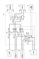
- FIG. 5 is a flowchart showing a series of processes of a defibrillation method performed by the defibrillation apparatus shown in FIG.
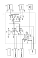
- FIG. 6 is a diagram showing an example of the connection state of the switching circuit in map mode.
- 7 to 10 are diagrams showing an example of the connection state of the switching circuit during resistance value measurement in the intracardiac defibrillation mode.
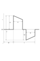
- FIG. 11 is a diagram showing the waveform of the voltage applied by the power supply circuit shown in FIG. 1.
- 12 to 15 are diagrams showing an example of the connection state of the switching circuit when voltage is applied in the intracardiac defibrillation mode.
- illustration of the connector is omitted, and the path to which the electrode group 22 is connected and the path to which the electrode group 23 is connected are shown separately. has been done.
- the defibrillation catheters 2A and 2B are inserted into the heart chamber of the patient P, and the electrode group 22 of each defibrillation catheter is placed at a desired position.
- a return electrode plate 3 is attached to a desired position on the body surface of the patient P.
- the power of the defibrillator 10 is turned on and the defibrillator 10 is activated.
- the defibrillation catheter 2A is connected to the connector 10a of the defibrillator 10
- the defibrillation catheter 2B is connected to the connector 10b of the defibrillator 10
- the return electrode 3 is connected to the connector 10c of the defibrillator 10. be done.
- the defibrillator 10 is activated, the defibrillator 10 is operating in map mode.
- the contacts 43a and 43d of the switch 43 are connected, the contacts 44a and 44d of the switch 44 are connected, and the contacts 44a and 44d of the switch 46 are connected.
- Contact 46a and contact 46b are connected, and contact 47a and contact 47b of switch 47 are connected.
- the electrode group 22 and the electrode group 23 of the defibrillation catheter 2A and the electrode group 22 and the electrode group 23 of the defibrillation catheter 2B are connected to the electrocardiograph 4.
- the switch 45 may be set to either a conductive state or a cutoff state.
- the switch 41 is set so that the contact 41a is not connected to any contact.
- the switch 42 is set so that the contact 42a is not connected to any contact.
- the intracardiac potentials measured by the electrode group 22 and electrode group 23 of the defibrillation catheter 2A and the electrode group 22 and the electrode group 23 of the defibrillation catheter 2B are output to the electrocardiograph 4. Then, the intracardiac potential is output from the electrocardiograph 4 to the defibrillator 10, and the arithmetic processing unit 15 receives the intracardiac potential. Then, the arithmetic processing unit 15 outputs the intracardiac potential to the display unit 11a, and causes the display unit 11a to display the intracardiac potential. In this state, in response to the intracardiac defibrillation mode being selected by the user operating the changeover switch, a series of processes shown in FIG. 5 is started.
- the arithmetic processing unit 15 determines whether a combination used for intracardiac defibrillation mode is selected from the defibrillation catheters 2A, 2B and the return electrode plate 3. (Step S1).
- selectable combination candidates are displayed on the display unit 11a.
- Candidates for combinations that can be selected are combinations of members to which voltages of different polarities are applied, such as a combination of the defibrillation catheter 2A and the defibrillation catheter 2B, a combination of the defibrillation catheter 2A and the return electrode plate 3, and a defibrillation catheter 2A and the defibrillation catheter 2B.
- step S1 determines that no combination has been selected. If the arithmetic processing unit 15 determines that no combination has been selected (step S1: NO), it repeats step S1 until a combination is selected. On the other hand, when the user selects a desired combination to be used for defibrillation from among the combination candidates, the arithmetic processing unit 15 determines that the combination has been selected (step S1: YES) and starts the resistance value measurement process. (Step S2).
- step S2 first, the arithmetic processing unit 15 determines the connection state of the switching circuit 14 in order to measure the resistance value between two electrodes (members) to which voltages of mutually different polarities are supplied, which are included in the selected combination. Set the connection status according to the selected combination. At this time, although the intracardiac potential (intracardial electrocardiogram) produced by the electrode group 22 is no longer displayed on the display section 11a, the intracardiac potential (intracardial electrocardiogram) produced by the electrode group 23 is displayed. Then, the arithmetic processing unit 15 causes the measuring device 13 to measure the resistance value between the measuring terminal 13a and the measuring terminal 13b.
- the intracardiac potential intracardial electrocardiogram
- connection states of the switching circuit 14 during resistance value measurement in the intracardiac defibrillation mode will be described with reference to FIGS. 7 to 10.
- the connection state of the switching circuit 14 is set to the connection state shown in FIG. 7. Specifically, the contacts 41a and 41c of the switch 41 are connected, the contacts 42a and 42c of the switch 42 are connected, the contacts 43a and 43b of the switch 43 are connected, and the contacts 44a of the switch 44 are connected. and contact 44c are connected.
- the switch 45 is set to the cutoff state, the contacts 46a and 46b of the switch 46 are connected, and the contacts 47a and 47b of the switch 47 are connected.
- the electrode group 22 of the defibrillation catheter 2A is connected to the measurement terminal 13a, and the electrode group 22 of the defibrillation catheter 2B is connected to the measurement terminal 13b. Therefore, the resistance value between the electrode group 22 of the defibrillation catheter 2A and the electrode group 22 of the defibrillation catheter 2B is measured.
- connection state of the switching circuit 14 is set to the connection state shown in FIG. 8.
- the connection state shown in FIG. 8 differs from the connection state shown in FIG. 7 in that the switch 45 is set to a conductive state.
- the electrode group 22 and the return electrode plate 3 of the defibrillation catheter 2A are connected to the measurement terminal 13a, and the electrode group 22 of the defibrillation catheter 2B is connected to the measurement terminal 13b. Therefore, the resistance value between the electrode group 22 and the return electrode plate 3 of the defibrillation catheter 2A and the electrode group 22 of the defibrillation catheter 2B is measured.
- the combined resistance value of the circuit in which the two are connected in parallel is measured.
- connection state of the switching circuit 14 is set to the connection state shown in FIG. 9.
- the connection state shown in FIG. 9 differs from the connection state shown in FIG. 8 in the connection state of the switches 43 and 44. Specifically, contacts 43a and 43c of switch 43 are connected, and contacts 44a and 44b of switch 44 are connected. According to this configuration, the electrode group 22 and the return electrode plate 3 of the defibrillation catheter 2B are connected to the measurement terminal 13a, and the electrode group 22 of the defibrillation catheter 2A is connected to the measurement terminal 13b.
- the resistance value between the electrode group 22 and the return electrode plate 3 of the defibrillation catheter 2B and the electrode group 22 of the defibrillation catheter 2A is measured.
- the resistance component between the electrode group 22 of the defibrillation catheter 2B and the electrode group 22 of the defibrillation catheter 2A, and the resistance component between the return electrode 3 and the electrode group 22 of the defibrillation catheter 2A is measured.
- connection state of the switching circuit 14 is set to the connection state shown in FIG. 10.
- the connection state shown in FIG. 10 differs from the connection state shown in FIG. 9 in the connection state of the switch 44. Specifically, contacts 44a and 44c of the switch 44 are connected. According to this configuration, the return electrode plate 3 is connected to the measurement terminal 13a, and the electrode group 22 of the defibrillation catheters 2A, 2B is connected to the measurement terminal 13b. Therefore, the resistance value between the return electrode plate 3 and the electrode group 22 of the defibrillation catheters 2A, 2B is measured.
- the measuring device 13 outputs the measured resistance value to the arithmetic processing section 15.
- the arithmetic processing unit 15 determines whether the resistance value is within an appropriate range (step S3).
- the appropriate range is set in advance for each combination.
- the appropriate range is the range of resistance values that can be measured when the members included in the combination are properly placed. If it is determined that the resistance value is within the appropriate range (step S3: YES), the arithmetic processing unit 15 sets the charging switch to be operable and determines whether or not a charging command has been received (step S4). If the calculation processing unit 15 determines that it has not received the charging command (step S4: NO), it repeats step S4 until it receives the charging command. Note that the charging switch is set to be inoperable until it is determined in step S3 that the resistance value is within the appropriate range.
- the arithmetic processing unit 15 receives the charging command (step S4: YES) and performs the charging process ( Step S5).
- the arithmetic processing unit 15 controls the power supply circuit 12 so that the defibrillation energy (voltage) set by the setting switch is charged to the capacitor of the power supply circuit 12. Defibrillation energy is set to 10J, for example.
- the time required to charge the capacitor is, for example, about 5 seconds.
- the arithmetic processing unit 15 determines whether a discharge command has been received before a predetermined time has elapsed since the completion of charging (step S6).
- the predetermined time is set to, for example, about 10 seconds.
- the calculation processing unit 15 receives the discharge command (step S6: YES) and performs a discharge process (step S7). ).
- step S7 first, the arithmetic processing unit 15 changes the connection state of the switching circuit 14 according to the selected combination in order to apply voltages of mutually different polarities to the two members (electrodes) included in the selected combination. connection status.
- the arithmetic processing unit 15 measures the peak of the R wave by arithmetic processing the body surface signal input from the induction electrode via the connector 10g.
- the arithmetic processing unit 15 then outputs a trigger signal to the power supply circuit 12 in synchronization with the peak of the R wave.
- the method of calculating the R wave peak will be explained in detail.
- the arithmetic processing unit 15 samples the body surface electrocardiogram at a predetermined period, detects the peak of the R wave, and measures the rise time and fall time of the R wave.
- the sampling period is set to 1 millisecond, for example. Since the R wave starts to fall when it reaches its peak, the arithmetic processing unit 15 detects the peak by monitoring the rise and fall of the R wave.
- the arithmetic processing unit 15 determines whether the R wave has a normal waveform (Narrow) or an abnormal waveform (Wide). For example, the arithmetic processing unit 15 determines that the R wave has a normal waveform if the time from the start of rising of the R wave to the peak of the R wave (rise time) is within 45 milliseconds. If the time from the start of the rise of the R wave to the peak of the R wave (rise time) is longer than 45 milliseconds, the arithmetic processing unit 15 determines that the R wave has an abnormal waveform.
- the arithmetic processing unit 15 outputs a trigger signal in response to the elapse of time t0 (see FIG. 11) from the peak of the R wave. If voltage is not applied within 60 milliseconds of the R-wave peak, there is a risk of inducing ventricular fibrillation. Therefore, the time t0 is, for example, 10 to 50 milliseconds. In this embodiment, time t0 is set to 10 milliseconds. Note that the conditions for determining a normal waveform, the conditions for determining an abnormal waveform, and the time t0 are configured to be settable by the user.
- one of the intracardiac potentials selected by the user using the operating device 11 is input to the arithmetic processing unit 15 via the connector 10f. Ru.
- the arithmetic processing unit 15 may output a trigger signal to the power supply circuit 12 in synchronization with the peak of the intracardiac potential input from the electrocardiograph 4 via the connector 10f.
- the method for outputting the trigger signal is the same as when a body surface electrocardiogram measured by an induction electrode is used.
- the arithmetic processing unit 15 may directly use the intracardiac potential measured by the electrode group 23 of the defibrillation catheter 2A and the intracardiac potential measured by the electrode group 23 of the defibrillation catheter 2B. In this case, the arithmetic processing unit 15 controls the switching circuit 14 so that the contacts 46a and 46c of the switch 46 are connected, and the contacts 47a and 47c of the switch 47 are connected.
- the arithmetic processing unit 15 processes the body surface signal with priority and detects the peak of the R wave. Good too.
- the power supply circuit 12 releases the defibrillation energy (voltage) charged in the capacitor of the power supply circuit 12.
- the power supply circuit 12 applies a biphasic voltage between the output terminal 12a and the output terminal 12b.
- the horizontal axis of the graph in FIG. 11 represents time, and the vertical axis represents potential.
- the power supply circuit 12 applies a voltage between the output terminal 12a and the output terminal 12b so that the output terminal 12a becomes a positive electrode and the output terminal 12b becomes a negative electrode.
- the voltage applied between the output terminals 12a and 12b is discharged from the capacitor, and therefore attenuates over time.
- the power supply circuit 12 stops applying the voltage and connects the output terminal 12a and the output terminal so that the output terminal 12a becomes the negative electrode and the output terminal 12b becomes the positive electrode. 12b, a voltage whose positive and negative polarities are reversed is applied.
- the arithmetic processing unit 15 outputs a stop signal to the power supply circuit 12, and upon receiving the stop signal, the power supply circuit 12 stops applying the voltage. Stop.
- the time t1 and the time t2 are, for example, 1.5 milliseconds to 10.0 milliseconds.
- the magnitude (absolute value) of the peak voltage V1 is, for example, 300V to 500V.
- the power supply circuit 12 may apply a single-phase voltage between the output terminal 12a and the output terminal 12b.
- the time t is, for example, 1.0 milliseconds to 30.0 milliseconds. In this embodiment, time t is 20.0 milliseconds. Note that although it takes time to switch the polarity of the voltage, that time is extremely short. Therefore, time t is slightly larger than, but substantially equal to, the sum of time t1 and time t2.
- connection states of the switching circuit 14 during voltage application in the intracardiac defibrillation mode will be described with reference to FIGS. 12 to 15.
- connection state of the switching circuit 14 is set to the connection state shown in FIG. 12.
- the connection state shown in FIG. 12 differs from the connection state shown in FIG. 7 in the connection state of the switches 41 and 42. Specifically, contacts 41a and 41b of switch 41 are connected, and contacts 42a and 42b of switch 42 are connected. According to this configuration, the electrode group 22 of the defibrillation catheter 2A is connected to the output terminal 12a, and the electrode group 22 of the defibrillation catheter 2B is connected to the output terminal 12b.
- a voltage is applied from the output terminal 12a to the electrode group 22 of the defibrillation catheter 2A, and a voltage is applied from the output terminal 12b to the electrode group 22 of the defibrillation catheter 2B. Therefore, defibrillation energy is applied between the electrode group 22 of the defibrillation catheter 2A and the electrode group 22 of the defibrillation catheter 2B.
- connection state of the switching circuit 14 is set to the connection state shown in FIG. 13.
- the connection state shown in FIG. 13 is different from the connection state shown in FIG. 8 in the connection state of the switches 41 and 42. Specifically, contacts 41a and 41b of switch 41 are connected, and contacts 42a and 42b of switch 42 are connected. According to this configuration, the electrode group 22 and the return electrode plate 3 of the defibrillation catheter 2A are connected to the output terminal 12a, and the electrode group 22 of the defibrillation catheter 2B is connected to the output terminal 12b.
- connection state of the switching circuit 14 is set to the connection state shown in FIG. 14.
- the connection state shown in FIG. 14 differs from the connection state shown in FIG. 9 in the connection state of the switches 41 and 42. Specifically, contacts 41a and 41b of switch 41 are connected, and contacts 42a and 42b of switch 42 are connected. According to this configuration, the electrode group 22 and the return electrode plate 3 of the defibrillation catheter 2B are connected to the output terminal 12a, and the electrode group 22 of the defibrillation catheter 2A is connected to the output terminal 12b.
- connection state of the switching circuit 14 is set to the connection state shown in FIG. 15.
- the connection state shown in FIG. 15 differs from the connection state shown in FIG. 10 in the connection state of the switches 41 and 42. Specifically, contacts 41a and 41b of switch 41 are connected, and contacts 42a and 42b of switch 42 are connected. According to this configuration, the return electrode plate 3 is connected to the output terminal 12a, and the electrode group 22 of the defibrillation catheters 2A, 2B is connected to the output terminal 12b.
- a voltage is applied to the return electrode plate 3 from the output terminal 12a, and a voltage is applied from the output terminal 12b to the electrode group 22 of the defibrillation catheter 2A and the electrode group 22 of the defibrillation catheter 2B. Therefore, defibrillation energy is applied between the return electrode plate 3 and the electrode group 22 of the defibrillation catheter 2A, and between the return electrode plate 3 and the electrode group 22 of the defibrillation catheter 2B.
- step S7 When the discharge process in step S7 is completed, the arithmetic processing unit 15 switches the operation mode of the defibrillator 10 to map mode (step S9).
- step S9 the arithmetic processing unit 15 sets the connection state of the switching circuit 14 to the connection state shown in FIG. 6. With the above, the series of processing shown in FIG. 5 is completed.
- step S6 if the arithmetic processing unit 15 does not receive a discharge command by the time a predetermined time has elapsed from the completion of charging (step S6: NO), the arithmetic processing unit 15 internally discharges the capacitor of the power supply circuit 12 (step S8). ). Then, the arithmetic processing unit 15 switches the operation mode of the defibrillator 10 to map mode (step S9). With the above, the series of processing shown in FIG. 5 is completed.
- step S3 If it is determined in step S3 that the resistance value is outside the appropriate range (step S3: NO), the arithmetic processing unit 15 switches the operation mode of the defibrillator 10 to map mode (step S9). With the above, the series of processing shown in FIG. 5 is completed. Note that if the resistance value is outside the appropriate range, it is considered that the electrode group 22 or the return electrode plate 3 is not properly placed. Therefore, the user re-places the defibrillation catheters 2A, 2B and the return electrode plate 3, which are used for defibrillation, at appropriate positions while checking the intracardiac potential. Thereafter, when the user selects the intracardiac defibrillation mode by operating the changeover switch, the series of processes shown in FIG. 5 is restarted.
- the defibrillation catheter 2A has the electrode group 22, and the defibrillation catheter 2B has the electrode group 22.
- the electrode group 22 of the defibrillation catheter 2A and the electrode group 22 of the defibrillation catheter 2B can be placed in a position close to the location where the myocardium is undergoing convulsion.
- defibrillation energy can be efficiently applied to the location where the myocardium is undergoing convulsion.
- the defibrillator 10 may apply a voltage with a polarity different from the polarity of the voltage applied to the electrode group 22 of the defibrillation catheter 2A to the electrode group 22 of the defibrillation catheter 2B. According to this configuration, defibrillation energy can be applied between the electrode group 22 of the defibrillation catheter 2A and the electrode group 22 of the defibrillation catheter 2B.
- the defibrillation device 10 may apply a voltage to the return electrode plate 3 with a polarity different from the polarity of the voltage applied to the electrode group 22 of the defibrillation catheter 2A. According to this configuration, defibrillation energy can be applied between the electrode group 22 and the return electrode plate 3 of the defibrillation catheter 2A. Similarly, the defibrillator 10 may apply a voltage to the return electrode 3 with a polarity different from the polarity of the voltage applied to the electrode group 22 of the defibrillator catheter 2B. According to this configuration, defibrillation energy can be applied between the electrode group 22 and the return electrode plate 3 of the defibrillation catheter 2B.
- the switching circuit 14 connects the members of the electrode group 22 of the defibrillation catheter 2A, the electrode group 22 of the defibrillation catheter 2B, and the return electrode plate 3 that are connected to the output terminal 12a of the power supply circuit 12;
- the member connected to the output terminal 12b can be selectively switched. Specifically, a combination of a member connected to the output terminal 12a and a member connected to the output terminal 12b is selected depending on the connection state of the switches 41 to 45. According to this configuration, defibrillation can be performed using a combination selected from the electrode group 22 of the defibrillation catheter 2A, the electrode group 22 of the defibrillation catheter 2B, and the return electrode plate 3. Therefore, an appropriate combination can be selected depending on the location where fibrillation has occurred, and defibrillation efficiency can be improved.
- the switching circuit 14 selectively applies a combination selected from the electrode group 22 of the defibrillation catheter 2A, the electrode group 22 of the defibrillation catheter 2B, and the return electrode to either the power supply circuit 12 or the measuring device 13. Connecting. According to this configuration, the defibrillator 10 can be made smaller compared to a configuration in which a path for supplying voltage and a path for measuring resistance value are provided separately.
- the switching circuit 14 selects between a state in which the electrode group 22 of the defibrillation catheter 2A is connected to the power supply circuit 12 and a state in which the electrode group 22 of the defibrillation catheter 2A is connected to the electrocardiograph 4. can be switched.
- the switching circuit 14 selects between a state in which the electrode group 22 of the defibrillation catheter 2B is connected to the power supply circuit 12 and a state in which the electrode group 22 of the defibrillation catheter 2B is connected to the electrocardiograph 4. can be switched.
- the electrocardiograph 4 measures the potentials of the plurality of electrodes 22a of the defibrillation catheter 2A and the potentials of the plurality of electrodes 22a of the defibrillation catheter 2B. According to this configuration, intracardiac potential can be measured without using an electrophysiological testing catheter.
- the defibrillation catheters 2A and 2B have an electrode group 23 including a plurality of electrodes 23a.
- the electrocardiograph 4 measures the potential of the electrode group 23 of the defibrillation catheter 2A and the potential of the electrode group 23 of the defibrillation catheter 2B. Therefore, intracardiac potential can be measured without using an electrophysiological testing catheter.
- the arithmetic processing unit 15 applies a voltage to the power supply circuit 12 in synchronization with the R wave or the peak of the intracardiac potential. Therefore, the induction of ventricular fibrillation can be prevented by applying a voltage before 60 milliseconds have elapsed from the peak of the R wave or intracardiac potential.
- the electrodes In a configuration in which a long electrode in which a plurality of electrodes 22a are integrated is used, the electrodes extend in the axial direction of the tube 21, which reduces the flexibility and pliability of the defibrillation catheter.
- the plurality of electrodes 22a are provided on the outer peripheral surface of the tube 21 and arranged in the axial direction of the tube 21. Therefore, the flexibility and pliability of the defibrillation catheters 2A, 2B can be increased compared to a configuration in which long electrodes are used. Therefore, it becomes possible to improve the operability of the defibrillation catheters 2A, 2B.
- the distal tip 26 is provided at the distal end 21a of the tube 21, and one end of a pull wire 27 is fixed to the distal tip 26 at a position eccentric to the central axis of the tube 21. ing. Therefore, by moving the pull wire 27 forward and backward using the operating lever 28b, a force is applied to the distal tip 26 at a position eccentric to the central axis. Therefore, the tip of the tube 21 (defibrillation catheters 2A, 2B) can be deflected. As a result, the operability of the defibrillation catheters 2A, 2B can be improved.
- Each electrode 22a has a curved shape that is convex in a direction intersecting the axial direction of the tube 21. According to this configuration, the surface area of the electrode 22a can be increased without increasing the length of the electrode 22a in the axial direction of the tube 21. Therefore, the possibility of damaging surrounding tissues can be reduced without impairing the operability of the defibrillation catheters 2A, 2B.
- the power supply circuit 12 and the measuring instrument 13 are selectively connected to the selected combination. Therefore, when a voltage is applied, the measuring device 13 is electrically isolated from the path to which the voltage is applied. On the other hand, when the resistance value of the path to which voltage is applied is measured, the power supply circuit 12 is electrically disconnected from the path. Therefore, it is possible to downsize the defibrillator 10 and prevent the power supply circuit 12 and the measuring device 13 from interfering with each other.
- intracardiac defibrillation system is not limited to the above embodiments.
- the intracardiac defibrillation system 1 may further include one or more defibrillation catheters having a similar configuration to the defibrillation catheters 2A and 2B.
- Defibrillation device 10 may include as many connectors for connecting defibrillation catheters as there are defibrillation catheters.
- the intracardiac defibrillation system 1 may not include the return electrode plate 3. In this case, the defibrillator 10 does not need to include the connector 10c.
- the intracardiac defibrillation system 1 may include two or more return electrode plates 3.
- the defibrillator 10 may include the same number of return electrode connectors as the number of return electrode plates 3.
- the intracardiac defibrillation system 1 includes the return electrode plate 3, it does not need to include one of the defibrillation catheters 2A and 2B.
- Each electrode 22a may have a cylindrical shape having a substantially uniform outer diameter over the entire length of the electrode 22a in the axial direction of the tube 21.
- Each electrode 22a may be attached to the outer circumferential surface of the tube 21 so that no recess 22s is formed between the outer circumferential surface of the tube 21 and the outer circumferential surface of the electrode 22a.
- the defibrillation catheters 2A, 2B do not need to contain glue G.
- the defibrillation catheters 2A and 2B are configured to be able to deflect the distal end of the tube 21 using the pull wire 27, the mechanism for deflecting the distal end of the tube 21 is not limited to this.
- the defibrillation catheters 2A, 2B may include a leaf spring (see FIG. 20) to deflect the distal end of the tube 21 in a plane.
- the defibrillation catheters 2A, 2B do not need to include the pull wire 27.
- the handle 28 does not need to include the operating lever 28b.
- the defibrillation catheters 2A, 2B may further include a lumen tube 29.
- FIG. 16 is a schematic configuration diagram of a modified defibrillation catheter.
- FIG. 17 is a cross-sectional view taken along line XVII-XVII in FIG. 16.
- the defibrillation catheters 2A, 2B shown in FIGS. 16 and 17 mainly differ from the defibrillation catheters 2A, 2B shown in FIG. 2 in that they further include a lumen tube 29 and in the configuration of the handle 28.
- the lumen tube 29 is used as an insertion tube through which the guide wire 31 is inserted.
- the lumen tube 29 is disposed within the tube 21 and extends from the base end 21b to the distal end 21a. Specifically, the lumen tube 29 extends linearly in the axial direction of the tube 21.
- the distal end of the lumen tube 29 passes through the distal tip 26 and extends to the distal end of the distal tip 26.
- a proximal end of the lumen tube 29 passes through the handle 28.
- the lumen tube 29 is arranged coaxially with the tube 21, for example.
- the lumen tube 29 is made of highly insulating materials such as perfluoroalkyl vinyl ether copolymer (PFA) and polytetrafluoroethylene (PTFE).
- PFA perfluoroalkyl vinyl ether copolymer
- PTFE polytetrafluoroethylene
- the lumen tube 29 may be made of a material having antithrombotic properties produced by mixing antithrombotic substances such as heparin, prostaglandin, urokinase, and arginine derivatives into these materials. .
- the handle 28 differs from the handle 28 of the defibrillation catheters 2A, 2B shown in FIG. 2 mainly in that it does not include the operating lever 28b and in the arrangement of the connector 28d.
- the main body portion 28a also functions as a hub located at the end of the lumen tube 29. Examples of hub construction materials include thermoplastics such as polycarbonate, polyamide, polysulfone, polyarylate, and methacrylate-styrene copolymer.
- the connectors 28d are arranged in parallel to the main body portion 28a. In other words, the connector 28d is provided at a position off the center axis of the tube 21.
- a guide wire is inserted into the lumen tube 29 from the proximal end of the lumen tube 29, and passes through the defibrillation catheters 2A, 2B. Then, the defibrillation catheters 2A, 2B are moved to the affected area along the guide wire. Note that the defibrillation catheters 2A, 2B are also referred to as over-the-wire type catheters.
- the defibrillation catheters 2A, 2B by moving the defibrillation catheters 2A, 2B along the guide wire 31 with the guide wire 31 inserted into the blood vessel, the affected area can be reached. Therefore, the insertion work of the defibrillation catheters 2A, 2B can be simplified.
- FIG. 18 is a schematic configuration diagram of another modified example of a defibrillation catheter.
- the defibrillation catheters 2A, 2B shown in FIG. 18 mainly differ from the defibrillation catheters 2A, 2B shown in FIG. 16 in the shape of the lumen tube 29 and the configuration of the handle 28.
- the lumen tube 29 is arranged inside the tube 21 and extends from the outer peripheral surface of the tube 21 to the tip 21a. Specifically, the lumen tube 29 extends obliquely from the outer peripheral surface of the tube 21 to the central axis of the tube 21, and further extends along the central axis to the distal end of the distal tip 26.
- These defibrillation catheters 2A, 2B are also referred to as rapid exchange type.
- the handle 28 includes a main body portion 28a and a strain relief 28c.
- the main body portion 28a also functions as a connector and includes connector pins.
- Each lead wire 24a and each lead wire 25a are connected to a connector pin of the main body portion 28a.
- the defibrillation catheters 2A, 2B may further include a balloon 30.
- FIG. 19 is a schematic configuration diagram of yet another modified example of a defibrillation catheter.
- the defibrillation catheters 2A and 2B shown in FIG. 19 differ from the defibrillation catheters 2A and 2B shown in FIG. 16 mainly in that they further include a balloon 30, the use of the lumen tube 29, and the configuration of the handle 28. .
- the lumen tube 29 is used as a supply pipe for supplying fluid to the balloon 30.
- the fluid may be a gas or a liquid such as saline and contrast media.
- the constituent material of the lumen tube 29 may be any flexible fluororesin.
- constituent materials include highly insulating materials such as perfluoroalkyl vinyl ether copolymer (PFA) and polytetrafluoroethylene (PTFE).
- PFA perfluoroalkyl vinyl ether copolymer
- PTFE polytetrafluoroethylene
- the lumen tube 29 may be made of a material having antithrombotic properties produced by mixing antithrombotic substances such as heparin, prostaglandin, urokinase, and arginine derivatives into these materials. .
- the balloon 30 is a member that can be expanded (expanded) and deflated.
- the balloon 30 can be expanded into a spherical shape, for example.
- the balloon 30 is provided at the tip 21a of the tube 21. Specifically, the balloon 30 is attached to the distal tip 26.
- the volume of the balloon 30 increases and the balloon 30 is inflated.
- the volume of the balloon 30 is reduced and the balloon 30 is deflated.
- the balloon 30 is made of a material that has a certain degree of flexibility.
- materials include polyolefins such as polyethylene, polypropylene, and ethylene-propylene copolymers, polyesters such as polyethylene terephthalate, polyvinyl chloride, ethylene-vinyl acetate copolymers, and crosslinked ethylene-vinyl acetate copolymers. and thermoplastic resins such as polyurethane, polyamide, polyamide elastomer, silicone rubber, and latex rubber.
- the balloon 30 may have a single layer structure or a laminate structure of two or more layers.
- the outer surface of the balloon 30 may be coated with a substance having antithrombotic properties.
- the handle 28 differs primarily from the handle 28 of the defibrillation catheters 2A, 2B shown in FIG. 16 in that it further includes a hub 28e and in the placement of a connector 28d.
- the hub 28e is a member located at the terminal end of the lumen tube 29. Examples of materials for hub 28e include thermoplastic resins such as polycarbonate, polyamide, polysulfone, polyarylate, and methacrylate-styrene copolymer.
- the connector 28d is arranged in parallel with the hub 28e. In other words, the connector 28d is provided at a position off the center axis of the tube 21.
- the defibrillation catheters 2A, 2B are inserted into the blood vessel of the patient P with the balloon 30 deflated and wrapped around the outer peripheral surface of the tube 21.
- the balloon 30 When the balloon 30 is inflated by supplying fluid to the balloon 30 while the defibrillation catheters 2A, 2B are inserted into the blood vessel, the balloon 30 receives force from the blood flowing in the blood vessel. This allows the defibrillation catheters 2A, 2B to advance along with the flow of blood, thereby simplifying the insertion work of the defibrillation catheters 2A, 2B.
- the defibrillation catheters 2A and 2B are single-lumen catheters, but they may be multi-lumen catheters.
- the defibrillation catheters 2A, 2B may further include at least one of a lumen tube through which the lead wire group 24 extends, a lumen tube through which the lead wire group 25 extends, and a lumen tube through which the pull wire 27 extends. good.
- the defibrillation catheters 2A, 2B may further include a core filled between each lumen tube and the tube 21.
- the core is made of, for example, a nylon elastomer with low hardness.
- the defibrillation catheters 2A, 2B may include a blade provided between the tube 21 and the core instead of the blade 21c. Note that the blade does not need to be provided in the region of the tube 21 where the electrode group 22 is provided.
- FIG. 20 is a sectional view of yet another modified example of a defibrillation catheter.
- FIG. 21 is a cross-sectional view of the defibrillation catheter shown in FIG. 20 at another location.
- the cross section shown in FIG. 20 is a cross section of the defibrillation catheters 2A, 2B that intersects with the axial direction of the tube 21, and is a cross section at a position between the electrode group 22 and the electrode group 23.
- the defibrillation catheters 2A, 2B shown in FIGS. 20 and 21 further include a leaf spring 51, lumen tubes 52, 53, 54, and a core 55. , 2B.
- the leaf spring 51 is a member for changing the tip end 21a of the tube 21 in a planar manner.
- the leaf spring 51 has a rectangular flat plate shape and extends inside the tube 21 .
- the leaf spring 51 extends inside the lumen tube 54.
- the leaf spring 51 extends from the tip 21a to between the electrode group 22 and the electrode group 23.
- the leaf spring 51 may extend from the tip 21a to the middle of the electrode group 22.
- the leaf spring 51 is made of a material that has appropriate flexibility and can memorize its shape.
- Each of the lumen tubes 52, 53, and 54 is arranged within the tube 21 and extends from the base end 21b to the distal end 21a. More specifically, each of the lumen tubes 52, 53, and 54 extends linearly within the tube 21 in the axial direction of the tube 21.
- a group of lead wires 24 extends inside the lumen tube 52 .
- a lead wire group 25 extends inside the lumen tube 53 .
- a pull wire 27 and a leaf spring 51 extend inside the lumen tube 54 .
- Each of the lumen tubes 52, 53, and 54 is made of a highly insulating material such as perfluoroalkyl vinyl ether copolymer (PFA) and polytetrafluoroethylene (PTFE).
- PFA perfluoroalkyl vinyl ether copolymer
- PTFE polytetrafluoroethylene
- Each of the lumen tubes 52, 53, and 54 is made of a material with antithrombotic properties produced by incorporating antithrombotic substances such as heparin, prostaglandin, urokinase, and arginine derivatives into these materials. It may be configured by
- a core 55 is filled between the outer peripheral surfaces of the lumen tubes 52, 53, and 54 and the inner peripheral surface of the tube 21.
- the core 55 is made of, for example, a nylon elastomer with low hardness.
- the defibrillation catheters 2A and 2B of this modification have a leaf spring 51 for changing the tip 21a of the tube 21 in a planar manner. According to this configuration, the tip of the tube 21 can be deflected using the leaf spring 51. As a result, it becomes possible to improve the operability of the defibrillation catheters 2A, 2B.
- the defibrillation catheters 2A, 2B of this modification include a lead wire group 24 including a plurality of lead wires 24a, and a lumen tube 52 in which the lead wire group 24 extends. Lumen tube 52 is arranged within tube 21. The plurality of lead wires 24a electrically connect the plurality of electrodes 22a and the connector 10a. According to this configuration, since the lead wire group 24 extends inside the lumen tube 52, the lead wire group can be electrically isolated from other members arranged within the tubular member.
- the defibrillation catheters 2A and 2B of this modification have a lumen tube 54 into which the pull wire 27 extends. Lumen tube 54 is arranged within tube 21. According to this configuration, when the pull wire 27 is moved back and forth in order to deflect the tip of the tube 21, the pull wire 27 does not come into direct contact with the inner circumferential surface of the tube 21. This simplifies the deflection of the tip of the tube 21 and makes the inner circumferential surface of the tube 21 less susceptible to wear.
- the defibrillation catheters 2A and 2B of this modification include a core 55 filled between the outer peripheral surfaces of the lumen tubes 52, 53, and 54 and the inner peripheral surface of the tube 21. According to this configuration, the lead wire group can be more reliably electrically separated from other members disposed within the tubular member, and the inner circumferential surface of the tube 21 becomes even more difficult to wear.
- defibrillation catheters 2A and 2B shown in FIG. 20 do not need to include the leaf spring 51.
- the defibrillation catheters 2A and 2B shown in FIG. 20 may not include the core 55, and in that case, they may not include at least one of the lumen tubes 52, 53, and 54.
- the defibrillation catheters 2A, 2B shown in FIG. 20 may not include the pull wire 27.
- Intracardiac defibrillation system 2A... Defibrillation catheter (first defibrillation catheter), 2B... Defibrillation catheter (second defibrillation catheter), 3... Return electrode, 4... Electrocardiograph , 10... Defibrillator, 10a... Connector (first connector), 10b... Connector (second connector), 10c... Connector (third connector), 12... Power supply circuit, 12a... Output terminal (first terminal), 12b... Output terminal (second terminal), 13... Measuring device, 14... Switching circuit, 15... Arithmetic processing unit, 21... Tube (tubular member), 22...
- Electrode group (first electrode group, second electrode group), 22a...electrode (first electrode, second electrode), 22s...recess, 23...electrode group (third electrode group, fourth electrode group), 23a...electrode (third electrode, fourth electrode), 24...lead wire Group, 26... Tip tip, 27... Pull wire, 28b... Operation lever (operation part), 29... Lumen tube (supply tube, insertion tube), 30... Balloon, 31... Guide wire, 51... Leaf spring, 52, 53, 54...Lumen tube, G...Glue (insulating member).
Landscapes
- Health & Medical Sciences (AREA)
- Life Sciences & Earth Sciences (AREA)
- Heart & Thoracic Surgery (AREA)
- Animal Behavior & Ethology (AREA)
- General Health & Medical Sciences (AREA)
- Veterinary Medicine (AREA)
- Engineering & Computer Science (AREA)
- Biomedical Technology (AREA)
- Public Health (AREA)
- Biophysics (AREA)
- Medical Informatics (AREA)
- Surgery (AREA)
- Cardiology (AREA)
- Molecular Biology (AREA)
- Physics & Mathematics (AREA)
- Pathology (AREA)
- Radiology & Medical Imaging (AREA)
- Nuclear Medicine, Radiotherapy & Molecular Imaging (AREA)
- Child & Adolescent Psychology (AREA)
- Pulmonology (AREA)
- Anesthesiology (AREA)
- Hematology (AREA)
- Physiology (AREA)
- Electrotherapy Devices (AREA)
- Measurement And Recording Of Electrical Phenomena And Electrical Characteristics Of The Living Body (AREA)
- Media Introduction/Drainage Providing Device (AREA)
Applications Claiming Priority (2)
| Application Number | Priority Date | Filing Date | Title |
|---|---|---|---|
| JP2022076689A JP7263593B1 (ja) | 2022-05-06 | 2022-05-06 | 心腔内除細動システム |
| JP2022-076689 | 2022-05-06 |
Publications (1)
| Publication Number | Publication Date |
|---|---|
| WO2023214529A1 true WO2023214529A1 (ja) | 2023-11-09 |
Family
ID=86054482
Family Applications (1)
| Application Number | Title | Priority Date | Filing Date |
|---|---|---|---|
| PCT/JP2023/016506 Ceased WO2023214529A1 (ja) | 2022-05-06 | 2023-04-26 | 心腔内除細動システム |
Country Status (2)
| Country | Link |
|---|---|
| JP (3) | JP7263593B1 (enExample) |
| WO (1) | WO2023214529A1 (enExample) |
Cited By (1)
| Publication number | Priority date | Publication date | Assignee | Title |
|---|---|---|---|---|
| WO2025205717A1 (ja) * | 2024-03-27 | 2025-10-02 | 株式会社カネカ | 心腔内除細動カテーテルシステムおよび心腔内除細動カテーテルシステムの制御方法 |
Families Citing this family (4)
| Publication number | Priority date | Publication date | Assignee | Title |
|---|---|---|---|---|
| JP7263593B1 (ja) * | 2022-05-06 | 2023-04-24 | 学 朝妻 | 心腔内除細動システム |
| JP2025129734A (ja) * | 2024-02-26 | 2025-09-05 | 日本ライフライン株式会社 | 電源装置およびアブレーションシステム |
| WO2025205965A1 (ja) * | 2024-03-27 | 2025-10-02 | 株式会社カネカ | 心腔内除細動カテーテルシステムおよび心腔内除細動カテーテルシステムの制御方法 |
| WO2025205964A1 (ja) * | 2024-03-27 | 2025-10-02 | 株式会社カネカ | 心腔内除細動カテーテルシステムおよび心腔内除細動カテーテルシステムの制御方法 |
Citations (10)
| Publication number | Priority date | Publication date | Assignee | Title |
|---|---|---|---|---|
| US6181967B1 (en) * | 1994-04-04 | 2001-01-30 | Eckhard Alt | Atrial defibrillator apparatus and method of use |
| JP2001519216A (ja) * | 1997-10-14 | 2001-10-23 | ユニヴァーシティ・オヴ・アラバマ・アト・バーミンガム・リサーチ・ファンデイション | 二重ショックによって心房細動を除去するシステム |
| US20070100382A1 (en) * | 2005-10-31 | 2007-05-03 | Smits Karel F | Implantation of medical device with measurement of body surface potential |
| JP2010220778A (ja) * | 2009-03-23 | 2010-10-07 | Japan Lifeline Co Ltd | 心腔内除細動カテーテルシステム |
| JP2017507699A (ja) * | 2014-02-06 | 2017-03-23 | セント・ジュード・メディカル,カーディオロジー・ディヴィジョン,インコーポレイテッド | 面取りされたリング電極および可変シャフトを備えた細長医療機器 |
| WO2017149904A1 (ja) * | 2016-02-29 | 2017-09-08 | 日本ライフライン株式会社 | 心腔内除細動カテーテル |
| WO2019156059A1 (ja) * | 2018-02-06 | 2019-08-15 | 株式会社カネカ | カテーテルおよびその製造方法 |
| WO2020188642A1 (ja) * | 2019-03-15 | 2020-09-24 | 日本ライフライン株式会社 | 心腔内除細動カテーテル |
| JP2022117198A (ja) * | 2021-01-29 | 2022-08-10 | 株式会社ニューロシューティカルズ | 心房細動除細動システム |
| JP7263593B1 (ja) * | 2022-05-06 | 2023-04-24 | 学 朝妻 | 心腔内除細動システム |
-
2022
- 2022-05-06 JP JP2022076689A patent/JP7263593B1/ja active Active
-
2023
- 2023-04-05 JP JP2023061408A patent/JP7482283B2/ja active Active
- 2023-04-26 WO PCT/JP2023/016506 patent/WO2023214529A1/ja not_active Ceased
-
2024
- 2024-02-09 JP JP2024018869A patent/JP2024052698A/ja active Pending
Patent Citations (10)
| Publication number | Priority date | Publication date | Assignee | Title |
|---|---|---|---|---|
| US6181967B1 (en) * | 1994-04-04 | 2001-01-30 | Eckhard Alt | Atrial defibrillator apparatus and method of use |
| JP2001519216A (ja) * | 1997-10-14 | 2001-10-23 | ユニヴァーシティ・オヴ・アラバマ・アト・バーミンガム・リサーチ・ファンデイション | 二重ショックによって心房細動を除去するシステム |
| US20070100382A1 (en) * | 2005-10-31 | 2007-05-03 | Smits Karel F | Implantation of medical device with measurement of body surface potential |
| JP2010220778A (ja) * | 2009-03-23 | 2010-10-07 | Japan Lifeline Co Ltd | 心腔内除細動カテーテルシステム |
| JP2017507699A (ja) * | 2014-02-06 | 2017-03-23 | セント・ジュード・メディカル,カーディオロジー・ディヴィジョン,インコーポレイテッド | 面取りされたリング電極および可変シャフトを備えた細長医療機器 |
| WO2017149904A1 (ja) * | 2016-02-29 | 2017-09-08 | 日本ライフライン株式会社 | 心腔内除細動カテーテル |
| WO2019156059A1 (ja) * | 2018-02-06 | 2019-08-15 | 株式会社カネカ | カテーテルおよびその製造方法 |
| WO2020188642A1 (ja) * | 2019-03-15 | 2020-09-24 | 日本ライフライン株式会社 | 心腔内除細動カテーテル |
| JP2022117198A (ja) * | 2021-01-29 | 2022-08-10 | 株式会社ニューロシューティカルズ | 心房細動除細動システム |
| JP7263593B1 (ja) * | 2022-05-06 | 2023-04-24 | 学 朝妻 | 心腔内除細動システム |
Cited By (1)
| Publication number | Priority date | Publication date | Assignee | Title |
|---|---|---|---|---|
| WO2025205717A1 (ja) * | 2024-03-27 | 2025-10-02 | 株式会社カネカ | 心腔内除細動カテーテルシステムおよび心腔内除細動カテーテルシステムの制御方法 |
Also Published As
| Publication number | Publication date |
|---|---|
| JP7263593B1 (ja) | 2023-04-24 |
| JP2023165616A (ja) | 2023-11-16 |
| JP2023165531A (ja) | 2023-11-16 |
| JP7482283B2 (ja) | 2024-05-13 |
| JP2024052698A (ja) | 2024-04-11 |
Similar Documents
| Publication | Publication Date | Title |
|---|---|---|
| JP7263593B1 (ja) | 心腔内除細動システム | |
| JP7688153B2 (ja) | パルス場アブレーション装置および方法 | |
| CN113332568B (zh) | 一种球囊导管及冲击波发生系统 | |
| US6246914B1 (en) | High torque catheter and methods thereof | |
| JP4545216B1 (ja) | 心腔内除細動カテーテルシステム | |
| US6611720B2 (en) | High torque catheter possessing multi-directional deflectability and methods thereof | |
| US5044375A (en) | Unitary intravascular defibrillating catheter with separate bipolar sensing | |
| US7171275B2 (en) | High torque balloon catheter possessing multi-directional deflectability and methods thereof | |
| EP0356009A1 (en) | Catheter with contoured ablation electrode | |
| AU2017212715B2 (en) | Force sensing catheter with impedance-guided orientation | |
| JP4672802B1 (ja) | 心腔内除細動カテーテルシステム | |
| US11672973B2 (en) | Defibrillation catheter system, defibrillation power supply device and method for controlling defibrillation power supply device | |
| CN109922861B (zh) | 心腔内除颤导管系统 | |
| US11679269B2 (en) | Defibrillation catheter system, defibrillation power supply device and method for controlling defibrillation power supply device | |
| US20230211154A1 (en) | Intracardiac defibrillation catheter system | |
| JP2011167413A (ja) | 心腔内除細動カテーテルシステム | |
| US20060282124A1 (en) | Apparatus and method for cardioversion | |
| WO2025205965A1 (ja) | 心腔内除細動カテーテルシステムおよび心腔内除細動カテーテルシステムの制御方法 | |
| WO2025205947A1 (ja) | 除細動用カテーテルシステム | |
| JP2025152532A (ja) | 除細動用カテーテルシステム | |
| WO2025205964A1 (ja) | 心腔内除細動カテーテルシステムおよび心腔内除細動カテーテルシステムの制御方法 | |
| JP2019122862A (ja) | 心腔内除細動カテーテル | |
| JP2019150526A (ja) | 心腔内除細動カテーテル |
Legal Events
| Date | Code | Title | Description |
|---|---|---|---|
| 121 | Ep: the epo has been informed by wipo that ep was designated in this application |
Ref document number: 23799460 Country of ref document: EP Kind code of ref document: A1 |
|
| NENP | Non-entry into the national phase |
Ref country code: DE |
|
| 122 | Ep: pct application non-entry in european phase |
Ref document number: 23799460 Country of ref document: EP Kind code of ref document: A1 |