WO2023214445A1 - 位置推定装置、位置推定方法、及びプログラム - Google Patents
位置推定装置、位置推定方法、及びプログラム Download PDFInfo
- Publication number
- WO2023214445A1 WO2023214445A1 PCT/JP2022/019497 JP2022019497W WO2023214445A1 WO 2023214445 A1 WO2023214445 A1 WO 2023214445A1 JP 2022019497 W JP2022019497 W JP 2022019497W WO 2023214445 A1 WO2023214445 A1 WO 2023214445A1
- Authority
- WO
- WIPO (PCT)
- Prior art keywords
- flying object
- images
- position estimation
- estimating
- target image
- Prior art date
- Legal status (The legal status is an assumption and is not a legal conclusion. Google has not performed a legal analysis and makes no representation as to the accuracy of the status listed.)
- Ceased
Links
Images





Classifications
-
- G—PHYSICS
- G01—MEASURING; TESTING
- G01C—MEASURING DISTANCES, LEVELS OR BEARINGS; SURVEYING; NAVIGATION; GYROSCOPIC INSTRUMENTS; PHOTOGRAMMETRY OR VIDEOGRAMMETRY
- G01C3/00—Measuring distances in line of sight; Optical rangefinders
- G01C3/02—Details
- G01C3/06—Use of electric means to obtain final indication
-
- G—PHYSICS
- G06—COMPUTING OR CALCULATING; COUNTING
- G06T—IMAGE DATA PROCESSING OR GENERATION, IN GENERAL
- G06T7/00—Image analysis
- G06T7/60—Analysis of geometric attributes
- G06T7/62—Analysis of geometric attributes of area, perimeter, diameter or volume
-
- G—PHYSICS
- G06—COMPUTING OR CALCULATING; COUNTING
- G06T—IMAGE DATA PROCESSING OR GENERATION, IN GENERAL
- G06T7/00—Image analysis
- G06T7/70—Determining position or orientation of objects or cameras
- G06T7/73—Determining position or orientation of objects or cameras using feature-based methods
- G06T7/74—Determining position or orientation of objects or cameras using feature-based methods involving reference images or patches
-
- G—PHYSICS
- G01—MEASURING; TESTING
- G01P—MEASURING LINEAR OR ANGULAR SPEED, ACCELERATION, DECELERATION, OR SHOCK; INDICATING PRESENCE, ABSENCE, OR DIRECTION, OF MOVEMENT
- G01P3/00—Measuring linear or angular speed; Measuring differences of linear or angular speeds
- G01P3/36—Devices characterised by the use of optical means, e.g. using infrared, visible, or ultraviolet light
- G01P3/38—Devices characterised by the use of optical means, e.g. using infrared, visible, or ultraviolet light using photographic means
-
- G—PHYSICS
- G06—COMPUTING OR CALCULATING; COUNTING
- G06T—IMAGE DATA PROCESSING OR GENERATION, IN GENERAL
- G06T7/00—Image analysis
- G06T7/20—Analysis of motion
-
- G—PHYSICS
- G06—COMPUTING OR CALCULATING; COUNTING
- G06T—IMAGE DATA PROCESSING OR GENERATION, IN GENERAL
- G06T7/00—Image analysis
- G06T7/20—Analysis of motion
- G06T7/246—Analysis of motion using feature-based methods, e.g. the tracking of corners or segments
- G06T7/248—Analysis of motion using feature-based methods, e.g. the tracking of corners or segments involving reference images or patches
-
- G—PHYSICS
- G06—COMPUTING OR CALCULATING; COUNTING
- G06T—IMAGE DATA PROCESSING OR GENERATION, IN GENERAL
- G06T7/00—Image analysis
- G06T7/20—Analysis of motion
- G06T7/292—Multi-camera tracking
-
- G—PHYSICS
- G06—COMPUTING OR CALCULATING; COUNTING
- G06T—IMAGE DATA PROCESSING OR GENERATION, IN GENERAL
- G06T7/00—Image analysis
- G06T7/70—Determining position or orientation of objects or cameras
-
- G—PHYSICS
- G01—MEASURING; TESTING
- G01C—MEASURING DISTANCES, LEVELS OR BEARINGS; SURVEYING; NAVIGATION; GYROSCOPIC INSTRUMENTS; PHOTOGRAMMETRY OR VIDEOGRAMMETRY
- G01C3/00—Measuring distances in line of sight; Optical rangefinders
- G01C3/02—Details
- G01C3/06—Use of electric means to obtain final indication
- G01C3/08—Use of electric radiation detectors
-
- G—PHYSICS
- G06—COMPUTING OR CALCULATING; COUNTING
- G06T—IMAGE DATA PROCESSING OR GENERATION, IN GENERAL
- G06T2207/00—Indexing scheme for image analysis or image enhancement
- G06T2207/20—Special algorithmic details
- G06T2207/20076—Probabilistic image processing
-
- G—PHYSICS
- G06—COMPUTING OR CALCULATING; COUNTING
- G06T—IMAGE DATA PROCESSING OR GENERATION, IN GENERAL
- G06T2207/00—Indexing scheme for image analysis or image enhancement
- G06T2207/30—Subject of image; Context of image processing
- G06T2207/30232—Surveillance
-
- G—PHYSICS
- G06—COMPUTING OR CALCULATING; COUNTING
- G06T—IMAGE DATA PROCESSING OR GENERATION, IN GENERAL
- G06T2207/00—Indexing scheme for image analysis or image enhancement
- G06T2207/30—Subject of image; Context of image processing
- G06T2207/30241—Trajectory
Definitions
- the present invention relates to a position estimation device, a position estimation method, and a program.
- Patent Document 1 uses two image data obtained by two camera modules to recognize a flying bird, calculate the position of the flying bird, and calculate the position of the flying bird after a predetermined time. Each of the locations is estimated, and a sound signal is supplied to a plurality of speaker modules so that the sound reaches the estimated location.
- one example of the object of the present invention is to enable the position of a flying object to be estimated with a single photographing device.
- an image acquisition unit that acquires a plurality of images generated by a photographing device that photographs a target space that is a space in which a flying object is flying; a position estimation unit that estimates the position of the flying object by processing the plurality of images; Equipped with The position estimating unit is (1) Temporarily set the type of the flying object, (2) Identifying three or more images arranged in chronological order as a target image group, (3) For each of the plurality of images included in the target image group, estimating the distance from the photographing device to the flying object using the temporarily set type and the area of the flying object in the images belonging to the target image group; (4) Calculating the rate of change in the area of the flying object between the plurality of images included in the target image group; (5) estimating the speed of the flying object using the distance to the flying object and the position within the image in each of the plurality of images included in the target image group; (6) updating the type of the flying object using the speed and the rate of change in the area; (7) Repeat the processes
- a method for estimating the position of a flying object using the above-described position estimating device, and a program for realizing the above-described position estimating device are also provided.
- the position of a flying object can be estimated even with a single imaging device.
- FIG. 2 is a diagram for explaining a first example of a usage environment of a position estimating device according to an embodiment.
- FIG. 7 is a diagram for explaining a second example of the usage environment of the position estimation device.
- FIG. 2 is a diagram illustrating an example of a functional configuration of a position estimation device.
- FIG. 2 is a diagram illustrating an example of a hardware configuration of a position estimation device.
- FIG. 3 is a diagram for explaining an example of processing performed by the position estimation device.
- FIG. 3 is a diagram for explaining step S30.
- 6 is a diagram for explaining the processing shown in steps S20 to S60 of FIG. 5.
- FIG. FIG. 7 is a diagram for explaining a detailed example of step S90.
- FIG. 7 is a diagram for explaining a detailed example of step S90.
- FIG. 7 is a diagram for explaining a detailed example of step S90.
- FIG. 7 is a diagram for explaining a detailed example of step S90.
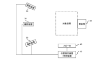
- FIG. 7 is a diagram for explaining a usage environment of a position estimating device according to a modified example.
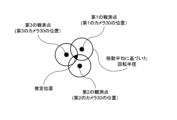
- FIG. 3 is a diagram for explaining an example of a method for specifying the estimated position of a flying object by a position estimating unit.
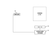
- FIG. 1 is a diagram for explaining a first example of a usage environment of a position estimating device 10 according to an embodiment.
- the position estimating device 10 is a device that detects a flying object existing around a structure 20 and estimates its position. In this detection and estimation, the position estimating device 10 uses an image generated by one photographing device 30.
- the imaging range of the imaging device 30 includes the target space.
- the target space includes areas into which flying objects should not enter. An example of this area is around the structure 20.
- the target space may or may not include the structure 20. Note that the target space includes, for example, both the structure 20 and a space within 2 km from the structure 20. However, depending on the type of imaging device 30, the target space may include a space within 10 km from the structure 20.
- flying objects are animals such as birds.
- the flying object may be another object, such as an airplane, a helicopter, or an object blown up by the wind.
- the structure 20 is, for example, a wind power generation device, but may be other equipment such as a steel tower. If the structure 20 has a mechanical or electrical structure, this structure is controlled by a control device. If the structure 20 is a wind power generator, this structure is a blade.
- the position estimating device 10 determines that the position of the flying object and its transition satisfy predetermined criteria and there is a possibility of colliding with the structure 20, the position estimating device 10 transmits predetermined information (control information to be described later) to the control device. transmit to stop or slow down the movement of a target or electrical structure. The control device then slows down or stops the movement of said structure.
- the photographing device 30 is a monocular camera. It is preferable that the photographing device 30 has a tilt function, a pan function, and a zoom function (hereinafter referred to as a TPZ function). It is desirable that the installation position of the photographing device 30 is fixed. Further, the frame rate of the image generated by the photographing device 30 is arbitrary. Note that the photographing device 30 may transmit, together with the generated image, a set value of the photographing device 30 at the time of generating the image, for example, a focal length, to the position estimation device 10.
- the installation position of the imaging device 30 may be determined using simulation, for example. In this case, by inputting the angle of view, installation position, and camera direction of the photographing device 30 into the simulation device, the range that can be photographed by the photographing device 30 can be calculated. Using this calculation result, it is possible to estimate the appropriate installation position of the photographing device 30.
- the position estimating device 10 estimates the current position of a flying object and also estimates the future position of the flying object.
- the position estimating device 10 controls the speaker 40 so that the sound reaches the animal at the timing when the animal reaches its future position. That is, the position estimation device 10 also functions as a control device for the speaker 40. At this time, the position estimating device 10 outputs a sound from the speaker 40 to convey predetermined information to the animal.
- An example of the sound that the position estimation device 10 causes the speaker 40 to output is a sound from the same species of the detected animal to convey predetermined information to this animal, or a sound from a related species of the detected animal to this animal. This is a sound that conveys specific information to the target.
- An example of certain information conveyed by sound is information that can change the animal's behavior, such as a sound to signal that a natural enemy is approaching, or that food is in a different location or direction. It is a sound to convey.
- the sound output by the speaker 40 is a sound to convey that a predator is approaching.
- the sound output by the speaker 40 is a sound to convey that an animal capable of complementary colors is in another location. That is, the position estimation device 10 changes the sound depending on the type of animal detected.
- the speaker 40 has directivity.
- An example of the speaker 40 is a parametric speaker.
- the direction of the speaker 40 is variable. The position estimating device 10 then controls the direction of the speaker 40 so that the output direction of the speaker 40 is directed toward the future position of the animal.
- FIG. 2 is a diagram for explaining a second example of the usage environment of the position estimation device 10.
- the position estimation device 10 predicts the future position of an animal that is about to invade a specific land (hereinafter referred to as a target area), and in order to prevent this animal from entering the target area. , controls the speaker 40.
- the target animals are, for example, boars, deer, monkeys, rats, or closely related species thereof, which are animals that cause so-called animal damage.
- "flying object” will be read as "animal” in the following description.
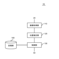
- FIG. 3 is a diagram showing an example of the functional configuration of the position estimation device 10.
- the position estimation device 10 includes an image acquisition section 110 and a position estimation section 120.
- the image acquisition unit 110 acquires a plurality of images photographed by the photographing device 30.
- the position estimation unit 120 estimates the position of the flying object by processing a plurality of images.
- the position estimation unit 120 performs the following processing. (1) Temporarily set the type of flying object. (2) Identify three or more images arranged in chronological order as a target image group, (3) For each of the multiple images included in the target image group, Estimate the distance from the photographing device to the flying object using the temporarily set type and the area of the flying object in images belonging to the target image group, (4) Calculate the rate of change in the area of the flying object between multiple images included in the target image group, (5) Estimating the speed of the flying object using the distance to the flying object and the position within the image in each of the plurality of images included in the target image group, (6) Update the type of projectile using the rate of change of velocity and area, (7) Repeat the processes shown in (2) to (6) using the type updated in (6) until a predetermined criterion is met. Then, based on the position of the flying object within the image and the distance calculated based on the image, the estimated position of the flying object at the timing when the image was taken is indicated.
- the position estimating unit 120 uses the focal length when the photographing device 30 generates the image.
- the position estimation unit 120 determines the average area of the area occupied by the flying object between the currently processed image and at least one other image belonging to the target image group. The distance is estimated using the average value. At this time, the position estimation unit 120 further generates motion information indicating the motion state of the flying object.
- the motion information includes at least one of the radius of rotation, angular velocity, acceleration, and angular acceleration when the trajectory of the flying object is approximated to a circular arc.
- the center of the rotation radius is the position of the imaging device 30.
- the position estimation unit 120 estimates the future position of the flying object.
- the future position is the result of estimating the position of the flying object at a first timing in the future. The first timing is after a predetermined time from now.
- This predetermined time is, for example, a value of 1/120 seconds or more and 5 seconds or less. It may be longer than this.
- the position estimating unit 120 uses information on the position, velocity, and motion of the flying object, and time-series information on at least one of these.
- the position estimation device 10 also functions as a control device that controls the speaker 40, and therefore includes a control section 130 and a storage section 140.
- the control unit 130 causes the speaker 40 to output a sound to convey predetermined information to the animal so that the sound reaches the future position at the first timing.
- predetermined information is as described using FIG. 1.
- the storage unit 140 stores data that becomes the sound source of the sound output by the speaker 40. Hereinafter, this data will be referred to as sound data.
- the storage unit 140 stores sound data by animal type, for example, by type. Then, the control unit 130 reads sound data corresponding to the type of animal detected by the position estimation unit 120 from the storage unit 140 and outputs it from the speaker 40.
- the speaker 40 has directivity, and its direction is variable.
- the control unit 130 controls the direction of the speaker 40.
- the control unit 130 controls the direction of the speaker 40 so that the output direction of the speaker 40 faces the future position of the animal.
- FIG. 4 is a diagram showing an example of the hardware configuration of the position estimation device 10.
- the position estimation device 10 has a bus 1010, a processor 1020, a memory 1030, a storage device 1040, an input/output interface 1050, and a network interface 1060.
- the bus 1010 is a data transmission path through which the processor 1020, memory 1030, storage device 1040, input/output interface 1050, and network interface 1060 exchange data with each other.
- the method of connecting the processors 1020 and the like to each other is not limited to bus connection.
- the processor 1020 is a processor implemented by a CPU (Central Processing Unit), a GPU (Graphics Processing Unit), or the like.
- the memory 1030 is a main storage device implemented by RAM (Random Access Memory) or the like.
- the storage device 1040 is an auxiliary storage device realized by a removable medium such as an HDD (Hard Disk Drive), an SSD (Solid State Drive), a memory card, or a ROM (Read Only Memory).
- the storage device 1040 stores program modules that implement each function of the position estimation device 10 (for example, the image acquisition unit 110, the position estimation unit 120, and the control unit 130).
- the processor 1020 reads each of these program modules onto the memory 1030 and executes them, each function corresponding to the program module is realized.
- the storage device 1040 also functions as the storage unit 140.
- the input/output interface 1050 is an interface for connecting the position estimation device 10 and various input/output devices.
- the position estimation device 10 may communicate with at least one of the imaging device 30 and the speaker 40 via the input/output interface 1050.
- the network interface 1060 is an interface for connecting the position estimation device 10 to a network.
- This network is, for example, a LAN (Local Area Network) or a WAN (Wide Area Network).
- the method by which the network interface 1060 connects to the network may be a wireless connection or a wired connection.
- the position estimation device 10 may communicate with at least one of the imaging device 30 and the speaker 40 via the network interface 1060.
- FIG. 5 is a diagram for explaining an example of processing performed by the position estimation device 10.
- the photographing device 30 repeatedly generates images. Every time the photographing device 30 generates an image, it immediately transmits the image to the position estimation device 10.
- the image acquisition unit 110 of the position estimation device 10 acquires these plurality of images and stores them in a storage unit, for example, the storage unit 140.
- the position estimation unit 120 determines whether the image contains a flying object. This process uses, for example, a process of determining whether a moving object exists within the image. If a flying object is included, the process shown in this figure is started.
- the position estimation unit 120 temporarily sets the type of flying object. This process corresponds to (1) described using FIG.
- the type set here is specified to the species of the animal (step S10).
- the position estimation unit 120 selects a predetermined number of images from the images stored in the storage unit 140.
- the predetermined number of sheets is at least three, but may be more than this.
- the plurality of images selected here will be referred to as a target image group.
- the plurality of images constituting the target image group are continuous in time series, and all include flying objects. For example, if the target image group is composed of three images, the target image group generated first is the image that initially included the flying object, the two images generated after that, (Step S20). This process corresponds to (2) described using FIG. 2.
- the position estimating unit 120 estimates the distance from the photographing device 30 to the flying object at the timing at which the image was photographed for each of the plurality of images forming the target image group (step S30).
- the estimated position of the flying object at the timing when each image is generated is indicated by the position of the flying object within the image and the distance calculated based on the image. This process corresponds to (3) described using FIG.
- FIG. 6 is a diagram for explaining step S30.
- the proportion of the area occupied by the flying object in the image (for example, the number of pixels) changes depending on the distance from the photographing device 30 to the flying object. Specifically, as the distance from the photographing device 30 to the flying object increases, the proportion of the area occupied by the flying object in the image decreases.
- the position estimation unit 120 uses this relationship to estimate the distance from the photographing device 30 to the flying object.
- the position estimation unit 120 uses the focal length of the photographing device 30 when the image was generated when calculating the distance from the photographing device 30 to the flying object. is preferable.
- the position estimation unit 120 calculates the velocity of the flying object, the radius of rotation when the trajectory of the flying object is approximated to an arc, the angular velocity, and the acceleration, using the position of the flying object at each timing when each image was captured. and estimate the angular acceleration (step S40). This process corresponds to (3) and (5) described using FIG. 2.
- the position of the flying object calculated in step S30 indicates the trajectory of the flying object. Using this trajectory, the radius of rotation of the flying object can be estimated. Further, by using the amount of change in the position of the flying object between at least two images adjacent to each other on the time axis, the velocity and acceleration of the flying object can be estimated. Further, by using the radius of rotation of the flying object and the amount of change in the position of the flying object between the two images described above, the angular velocity and angular acceleration of the flying object can be estimated.
- the position estimating unit 120 can perform the estimation shown in step S40, for example, on an image other than the image located first on the time axis among the plurality of images forming the target image group.
- the position estimation unit 120 calculates the rate of change in the area occupied by the flying object calculated in step S30, and calculates the average value of this area (step S50). This process corresponds to (4) explained using FIG.
- the position estimation unit 120 performs the following processing, excluding the last image on the time axis among the plurality of images forming the target image group. First, the ratio of the area of the flying object in that image to the area of the flying object in the next image is determined as an area change rate. Then, the average value of these two areas is calculated. These area change rates and average values are set to be located midway between the timings at which these two images were generated on the time axis. Note that when step S50 is performed, the number of data items decreases by one on the time axis.
- the position estimation unit 120 repeats the processes from step S30 to step S50 using the average value of the area calculated in step S50 until the first criterion is satisfied (step S60).
- An example of the first criterion is that the processes from step S30 to step S50 are repeated a predetermined number of times.
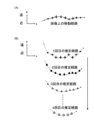
- FIG. 7 is a diagram for explaining the processing shown in steps S20 to S60 of FIG. 5.
- the target image group is composed of 10 images.
- 7(A) shows the moving path (trajectory) of the flying object on the image, that is, the trajectory projected on the xy plane, and each diagram in FIG. In other words, the estimated path of the flying object projected onto the xz plane is shown.
- the x-axis and the y-axis indicate two axes forming an image
- the z-axis indicates a direction away from the photographing device 30, as shown in FIG.
- step S50 when step S50 is performed, the number of data decreases by one on the time axis. Therefore, each time the processes shown in steps S20 to S50 are repeated, the number of measurement points indicating the estimated travel route, that is, the number of measurement timings decreases by one. Instead, the accuracy of estimating the distance, that is, the accuracy of estimating the position of the flying object, increases.
- step S70 the position estimation unit 120 determines whether it is necessary to update the target image group.
- An example of a case where it is necessary to update the target image group is, for example, that there remain images that have not yet been selected as the target image group. Further, a case where the image acquisition unit 110 has acquired a new image from the photographing device 30 is also an example of a case where it is necessary to update the target image group. If it is necessary to update the target image group (step S70: Yes), the position estimation unit 120 updates the target image group (step S20), and repeats the processes shown in steps S30 to S70.
- the target image group is updated using a first-in, first-out method. That is, the position estimation unit 120 removes the oldest image in time series from among the images included in the current target image group. Then, the position estimation unit 120 identifies the latest image among the images included in the current target image group, and newly adds the image located next to this image in time series to the target image group. In other words, each target image group corresponds to the timing at which the latest image of the target image group was photographed.
- the position estimation unit 120 calculates a moving average of each value calculated in steps S40 to S50 (step S80). This process corresponds to the process performed between (5) and (6) shown in FIG. Then, the position estimation unit 120 estimates the future position of the flying object using the moving average of the position and velocity (step S90).
- step S90 are diagrams for explaining detailed examples of step S90.
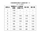
- the position estimation unit 120 first calculates the K-point moving average of the area of the flying object, the local minimum value within the K points, and the local maximum value within the K points for each target image group. Specifically, the position estimation unit 120 calculates a K-point moving average of the area of the flying object, and links the calculated average to the newest image in time series among the images used when calculating the moving average. . Furthermore, the position estimation unit 120 recognizes the area of the flying object in each of the K images used when calculating the moving average. Then, the position estimating unit 120 links each of the minimum and maximum values of these K areas to the newest image in time series among the images used when calculating the moving average. Thereby, the local minimum value and local maximum value of the area are linked to each of the plurality of images.
- the position estimating unit 120 calculates, for each target image group, an estimated movement path of the flying object based on the local minimum value (hereinafter referred to as a first estimated movement path) and a local maximum value of the area.
- An estimated travel route (hereinafter referred to as a second estimated travel route) based on the above is specified.
- the first estimated moving route indicates a moving route when the estimated distance from the photographing device 30 to the flying object is the maximum value of the estimated range (that is, when it is farthest from the photographing device 30).
- the second estimated movement route indicates a movement route when the estimated distance from the photographing device 30 to the flying object is the minimum value of the estimated range (that is, when it is closest to the photographing device 30).
- the range between these two estimated movement paths indicates the estimated range of the movement path of the flying object.
- the flying object is flying within this estimated range with a high probability. From this, the estimated movement route of the flying object can be shown as a band.
- the position estimating unit 120 specifies an estimated moving route (hereinafter referred to as a third estimated moving route) based on the moving average of the area.
- the third estimated moving route is located between the first estimated moving route and the second estimated moving route.
- the position estimating unit 120 calculates the rotation radius indicating the first estimated movement path (minimum value of area) and the second estimated movement path (maximum value of area) in each target image group. and a rotation radius representing the third estimated moving route (moving average of area).
- the position estimating unit 120 superimposes estimated movement routes based on each of the plurality of target image groups.
- Each of the plurality of target image groups corresponds to the time (t 0 , t 1 , t 2 . . . ) at which the latest image of the target image group was photographed.
- Each estimated movement route is shown as a circular arc centered on the position of the photographing device 30 and having a radius based on the third estimated movement route.
- the position estimation unit 120 estimates the future movement path of the flying object using the transition of these estimated movement paths, and estimates the future position of the flying object using this movement path.
- the position estimation unit 120 can estimate the future position of the flying object using a Kalman filter. In this case, the future position of the flying object can be predicted even if there are missing values. Furthermore, the robustness of predicting future positions is also improved.
- the moving average of the position, velocity, and motion information of the flying object is used to calculate the estimated movement route. For this reason, the prediction of the future position of the flying object essentially uses the moving average of each of the position, velocity, and motion information of the flying object.
- each estimated movement route estimates the future position of the flying object based on the first estimated latitude route (that is, the route furthest from the photographing device 30), and also estimates the future position of the flying object based on the second estimated latitude.
- the future position of the flying object may be estimated based on the route (that is, the route closest to the imaging device 30).
- the position estimation unit 120 may use these two future positions to calculate the future position that will actually be used. As an example, the position estimating unit 120 may set the average position of these two future positions as the actually used future position.
- the position estimation unit 120 estimates the type of the flying object using the speed and area change rate of the flying object (step S100). Both velocity and area change rate are characteristic of the movement of the projectile. For example, when the flying object is a bird, the speed range is determined by the species of bird, and the characteristics of the movement of the wings when flapping and the movement when turning vary depending on the species of bird. Therefore, the position estimating unit 120 can identify the type of flying object using the velocity and area change rate.
- the position estimating unit 120 estimates the species. This process corresponds to (6) described using FIG. 2.
- step S110 No
- the position estimation unit 120 returns to step S30.
- This process corresponds to (7) described using FIG. 2.
- the second criterion is, for example, either (a) or (b) below.
- step S30 to step S110 is repeated a preset number of times. This criterion is suitable when the processing by the position estimating unit 120 needs to proceed at a certain speed.
- the second criterion described above be switchable, for example, in accordance with input from the user.
- the control unit 130 reads sound data corresponding to the species of the animal from the storage unit 140. Furthermore, the control unit 130 directs the speaker 40 toward the future position specified in step S90. Then, the control unit 130 causes the speaker 40 to output the sound data read from the storage unit 140 (step S120). At this time, the control unit 130 controls the timing of emitting the sound so that the sound reaches the future position at the timing when the flying object is expected to reach the future position.
- the sound output from the speaker 40 is a sound for conveying predetermined information to the animal.
- animals recognize the information contained in this sound, they change their direction of movement accordingly. This prevents animals from entering areas where they should not enter. In this case, there is no need to intimidate the animals with the loudness of the sound. Therefore, the loudness of the sound emitted from the speaker 40 can be small compared to the conventional technology.
- the position and future position of a flying object can be estimated even with a single photographing device. Further, when the flying object is an animal such as a bird, even if the sound output from the speaker 40 is low, it is possible to prevent the animal from entering an area where it should not enter.
- FIG. 12 is a diagram for explaining the usage environment of the position estimating device 10 according to this modification.
- the position estimation device 10 is used together with one imaging device 30.
- the position estimation device 10 is used with a plurality of imaging devices 30, preferably three or more imaging devices 30.
- the plurality of photographing devices 30 are arranged apart from each other, and include the target space (or target area) in their photographing range. That is, the plurality of photographing devices 30 photograph the target space from mutually different directions.
- all of the plurality of photographing devices 30 are monocular cameras. In this way, the cost of the photographing device 30 is reduced.
- the image acquisition unit 110 of the position estimation device 10 acquires a plurality of images from the plurality of photographing devices 30, and the position estimation unit 120 of the position estimation device 10 indicates the estimated position of the flying object for each of the plurality of photographing devices 30.
- the information is calculated, and the estimated position of the flying object is specified using the information for each photographing device 30.
- An example of information indicating the estimated position of the flying object is the radius of rotation described using FIG. 10.
- the position estimating unit 120 performs processing up to calculating the radius of rotation for each of the plurality of imaging devices 30. Then, the position estimating unit 120 uses the calculation results of the plurality of rotation radii to specify the estimated position of the flying object.
- FIG. 13 is a diagram for explaining an example of a method for specifying the estimated position of a flying object by the position estimation unit 120.
- the position estimation unit 120 calculates the radius of rotation for each of the plurality of imaging devices 30. Then, the position estimating unit 120 draws a circle for each of the plurality of imaging devices 30, with the position of the imaging device 30 as the center and the radius of rotation corresponding to the imaging device 30. Then, the position estimating unit 120 estimates that a flying object exists at a location where these multiple circles overlap.
- the position estimating unit 120 uses the distance calculated in step S30 and the position of the flying object in the image to calculate the position of the flying object in the real space for each of the plurality of imaging devices 30, and calculates the results of these calculations.
- the average value may be used as the estimated position of the flying object.
- the position estimating unit 120 also calculates the band-shaped estimated movement paths shown in FIG. 9 for each of the plurality of imaging devices 30, and estimates that the flying object exists in the area where these plurality of estimated movement paths overlap. By doing so, the estimated travel route that will actually be used may be specified. In this case, since the accuracy of the estimated movement route increases, the accuracy of estimating the future position of the flying object also increases.
- the position estimating unit 120 uses the transition of the estimated position to identify the trajectory of the flying object, and uses this trajectory to estimate the future position. Then, the control unit 130 directs the speaker 40 to this future position, and then outputs sound from the speaker 40.
- the position estimating device 10 estimates the position of the flying object using images captured by the plurality of imaging devices 30. Therefore, the accuracy of estimating the position of the flying object increases. Further, each of the plurality of photographing devices 30 can use a monocular camera. Therefore, it is possible to increase the accuracy of estimating the position of the flying object while suppressing the cost of the photographing device 30.
- Position estimation device 20 Structure 30 Photographing device 40 Speaker 110 Image acquisition section 120 Position estimation section 130 Control section 140 Storage section
Landscapes
- Engineering & Computer Science (AREA)
- Physics & Mathematics (AREA)
- General Physics & Mathematics (AREA)
- Theoretical Computer Science (AREA)
- Computer Vision & Pattern Recognition (AREA)
- Electromagnetism (AREA)
- Multimedia (AREA)
- Power Engineering (AREA)
- Geometry (AREA)
- Radar, Positioning & Navigation (AREA)
- Remote Sensing (AREA)
- Image Analysis (AREA)
- Length Measuring Devices By Optical Means (AREA)
Priority Applications (7)
| Application Number | Priority Date | Filing Date | Title |
|---|---|---|---|
| KR1020247037851A KR20250005289A (ko) | 2022-05-02 | 2022-05-02 | 위치 추정 장치, 위치 추정 방법 및 기록 매체 |
| US18/861,726 US20250349030A1 (en) | 2022-05-02 | 2022-05-02 | Position estimation device, position estimation method, and storage medium |
| CA3257270A CA3257270A1 (en) | 2022-05-02 | 2022-05-02 | Position estimation device, position estimation method, and storage medium |
| JP2024519147A JPWO2023214445A1 (cg-RX-API-DMAC7.html) | 2022-05-02 | 2022-05-02 | |
| PCT/JP2022/019497 WO2023214445A1 (ja) | 2022-05-02 | 2022-05-02 | 位置推定装置、位置推定方法、及びプログラム |
| CN202280095688.9A CN119365751A (zh) | 2022-05-02 | 2022-05-02 | 位置推定装置、位置推定方法以及程序 |
| EP22940807.5A EP4521061A1 (en) | 2022-05-02 | 2022-05-02 | Position estimation device, position estimation method, and program |
Applications Claiming Priority (1)
| Application Number | Priority Date | Filing Date | Title |
|---|---|---|---|
| PCT/JP2022/019497 WO2023214445A1 (ja) | 2022-05-02 | 2022-05-02 | 位置推定装置、位置推定方法、及びプログラム |
Publications (1)
| Publication Number | Publication Date |
|---|---|
| WO2023214445A1 true WO2023214445A1 (ja) | 2023-11-09 |
Family
ID=88646389
Family Applications (1)
| Application Number | Title | Priority Date | Filing Date |
|---|---|---|---|
| PCT/JP2022/019497 Ceased WO2023214445A1 (ja) | 2022-05-02 | 2022-05-02 | 位置推定装置、位置推定方法、及びプログラム |
Country Status (7)
| Country | Link |
|---|---|
| US (1) | US20250349030A1 (cg-RX-API-DMAC7.html) |
| EP (1) | EP4521061A1 (cg-RX-API-DMAC7.html) |
| JP (1) | JPWO2023214445A1 (cg-RX-API-DMAC7.html) |
| KR (1) | KR20250005289A (cg-RX-API-DMAC7.html) |
| CN (1) | CN119365751A (cg-RX-API-DMAC7.html) |
| CA (1) | CA3257270A1 (cg-RX-API-DMAC7.html) |
| WO (1) | WO2023214445A1 (cg-RX-API-DMAC7.html) |
Families Citing this family (1)
| Publication number | Priority date | Publication date | Assignee | Title |
|---|---|---|---|---|
| CN121995947B (zh) * | 2026-04-08 | 2026-06-23 | 四川傲势科技有限公司 | 无人机控制方法、装置及电子设备 |
Citations (4)
| Publication number | Priority date | Publication date | Assignee | Title |
|---|---|---|---|---|
| JPH104858A (ja) | 1996-06-21 | 1998-01-13 | Takenaka Komuten Co Ltd | 鳥類飛来防止装置 |
| JP2015059749A (ja) * | 2013-09-17 | 2015-03-30 | 日本電気株式会社 | 物体検出装置、物体検出方法および物体検出システム |
| WO2015170776A1 (ja) * | 2014-05-07 | 2015-11-12 | 日本電気株式会社 | 物体検出装置、物体検出方法および物体検出システム |
| US20160050889A1 (en) * | 2014-08-21 | 2016-02-25 | Identiflight, Llc | Imaging array for bird or bat detection and identification |
-
2022
- 2022-05-02 US US18/861,726 patent/US20250349030A1/en active Pending
- 2022-05-02 JP JP2024519147A patent/JPWO2023214445A1/ja not_active Ceased
- 2022-05-02 CA CA3257270A patent/CA3257270A1/en active Pending
- 2022-05-02 KR KR1020247037851A patent/KR20250005289A/ko active Pending
- 2022-05-02 WO PCT/JP2022/019497 patent/WO2023214445A1/ja not_active Ceased
- 2022-05-02 CN CN202280095688.9A patent/CN119365751A/zh not_active Withdrawn
- 2022-05-02 EP EP22940807.5A patent/EP4521061A1/en not_active Withdrawn
Patent Citations (4)
| Publication number | Priority date | Publication date | Assignee | Title |
|---|---|---|---|---|
| JPH104858A (ja) | 1996-06-21 | 1998-01-13 | Takenaka Komuten Co Ltd | 鳥類飛来防止装置 |
| JP2015059749A (ja) * | 2013-09-17 | 2015-03-30 | 日本電気株式会社 | 物体検出装置、物体検出方法および物体検出システム |
| WO2015170776A1 (ja) * | 2014-05-07 | 2015-11-12 | 日本電気株式会社 | 物体検出装置、物体検出方法および物体検出システム |
| US20160050889A1 (en) * | 2014-08-21 | 2016-02-25 | Identiflight, Llc | Imaging array for bird or bat detection and identification |
Also Published As
| Publication number | Publication date |
|---|---|
| CA3257270A1 (en) | 2025-04-22 |
| JPWO2023214445A1 (cg-RX-API-DMAC7.html) | 2023-11-09 |
| US20250349030A1 (en) | 2025-11-13 |
| EP4521061A1 (en) | 2025-03-12 |
| CN119365751A (zh) | 2025-01-24 |
| KR20250005289A (ko) | 2025-01-09 |
Similar Documents
| Publication | Publication Date | Title |
|---|---|---|
| US12238403B2 (en) | Photographing control method, apparatus, and control device | |
| CN108594853B (zh) | 无人机队形控制方法 | |
| CA2947138A1 (en) | Object detection device, object detection method, and object detection system | |
| CN114729811A (zh) | 位置推断装置、车辆、位置推断方法及位置推断程序 | |
| US12266149B2 (en) | Own-position estimating device, moving body, own-position estimating method, and own-position estimating program | |
| CN116339321A (zh) | 一种基于5g通信的全局信息驱动的分布式多机器人强化学习编队合围方法 | |
| CN112180977A (zh) | 一种轨迹规划方法、装置、存储介质及飞行器 | |
| CN113924598A (zh) | 用于感测和避开外部物体的图像传感器数据的多路处理 | |
| CN120521614B (zh) | 一种用于无人艇集群多目标围捕的完全分布式目标中心估计方法 | |
| CN116225022A (zh) | 基于鸽子式思维优化无人机与无人船异构协同围捕方法 | |
| JP6530212B2 (ja) | 自律移動ロボット | |
| CN118092465B (zh) | 一种无人机航行控制方法及系统 | |
| JP6950273B2 (ja) | 飛行物体位置検知装置、飛行物体位置検知システム、飛行物体位置検知方法及びプログラム | |
| JP2024066408A (ja) | 作戦地域統合監視方法およびシステム | |
| EP4521061A1 (en) | Position estimation device, position estimation method, and program | |
| WO2023214447A1 (ja) | 制御装置、制御方法、及びプログラム | |
| CN121545396A (zh) | 无人机边端输电通道动态障碍物感知融合预警方法及系统 | |
| CN119270880B (zh) | 一种无人机集群编队控制方法及系统 | |
| JP2006270404A (ja) | 撮影制御装置、撮影制御方法および撮影制御プログラム | |
| Lu et al. | Target localization with drones using mobile CNNs | |
| JP2022142599A (ja) | 情報処理装置、情報処理方法及び情報処理システム | |
| CN119148739A (zh) | 基于人工势场法的无人机补点替换方法、装置、设备及介质 | |
| CN118795931A (zh) | 基于多无人机的协同对抗控制方法 | |
| WO2020111032A1 (ja) | 移動体の周囲状態判定用画像処理装置および方法 | |
| JP7231113B2 (ja) | 可視化制御装置、可視化システム、可視化制御方法およびコンピュータプログラム |
Legal Events
| Date | Code | Title | Description |
|---|---|---|---|
| 121 | Ep: the epo has been informed by wipo that ep was designated in this application |
Ref document number: 22940807 Country of ref document: EP Kind code of ref document: A1 |
|
| WWE | Wipo information: entry into national phase |
Ref document number: 2024519147 Country of ref document: JP |
|
| WWE | Wipo information: entry into national phase |
Ref document number: 18861726 Country of ref document: US |
|
| WWE | Wipo information: entry into national phase |
Ref document number: 202280095688.9 Country of ref document: CN |
|
| ENP | Entry into the national phase |
Ref document number: 20247037851 Country of ref document: KR Kind code of ref document: A |
|
| WWE | Wipo information: entry into national phase |
Ref document number: 1020247037851 Country of ref document: KR |
|
| WWE | Wipo information: entry into national phase |
Ref document number: 2022940807 Country of ref document: EP |
|
| NENP | Non-entry into the national phase |
Ref country code: DE |
|
| ENP | Entry into the national phase |
Ref document number: 2022940807 Country of ref document: EP Effective date: 20241202 |
|
| WWP | Wipo information: published in national office |
Ref document number: 202280095688.9 Country of ref document: CN |
|
| WWW | Wipo information: withdrawn in national office |
Ref document number: 1020247037851 Country of ref document: KR Ref document number: 2022940807 Country of ref document: EP |
|
| WWP | Wipo information: published in national office |
Ref document number: 18861726 Country of ref document: US |