WO2023210765A1 - 免疫隔離デバイス - Google Patents
免疫隔離デバイス Download PDFInfo
- Publication number
- WO2023210765A1 WO2023210765A1 PCT/JP2023/016713 JP2023016713W WO2023210765A1 WO 2023210765 A1 WO2023210765 A1 WO 2023210765A1 JP 2023016713 W JP2023016713 W JP 2023016713W WO 2023210765 A1 WO2023210765 A1 WO 2023210765A1
- Authority
- WO
- WIPO (PCT)
- Prior art keywords
- immunoisolation
- layer
- fibrous structure
- cell
- hydrogel
- Prior art date
- Legal status (The legal status is an assumption and is not a legal conclusion. Google has not performed a legal analysis and makes no representation as to the accuracy of the status listed.)
- Ceased
Links
Images





Classifications
-
- A—HUMAN NECESSITIES
- A61—MEDICAL OR VETERINARY SCIENCE; HYGIENE
- A61F—FILTERS IMPLANTABLE INTO BLOOD VESSELS; PROSTHESES; DEVICES PROVIDING PATENCY TO, OR PREVENTING COLLAPSING OF, TUBULAR STRUCTURES OF THE BODY, e.g. STENTS; ORTHOPAEDIC, NURSING OR CONTRACEPTIVE DEVICES; FOMENTATION; TREATMENT OR PROTECTION OF EYES OR EARS; BANDAGES, DRESSINGS OR ABSORBENT PADS; FIRST-AID KITS
- A61F2/00—Filters implantable into blood vessels; Prostheses, i.e. artificial substitutes or replacements for parts of the body; Appliances for connecting them with the body; Devices providing patency to, or preventing collapsing of, tubular structures of the body, e.g. stents
- A61F2/02—Prostheses implantable into the body
- A61F2/022—Artificial gland structures using bioreactors
-
- B—PERFORMING OPERATIONS; TRANSPORTING
- B01—PHYSICAL OR CHEMICAL PROCESSES OR APPARATUS IN GENERAL
- B01L—CHEMICAL OR PHYSICAL LABORATORY APPARATUS FOR GENERAL USE
- B01L3/00—Containers or dishes for laboratory use, e.g. laboratory glassware; Droppers
- B01L3/50—Containers for the purpose of retaining a material to be analysed, e.g. test tubes
- B01L3/502—Containers for the purpose of retaining a material to be analysed, e.g. test tubes with fluid transport, e.g. in multi-compartment structures
- B01L3/5027—Containers for the purpose of retaining a material to be analysed, e.g. test tubes with fluid transport, e.g. in multi-compartment structures by integrated microfluidic structures, i.e. dimensions of channels and chambers are such that surface tension forces are important, e.g. lab-on-a-chip
- B01L3/502761—Containers for the purpose of retaining a material to be analysed, e.g. test tubes with fluid transport, e.g. in multi-compartment structures by integrated microfluidic structures, i.e. dimensions of channels and chambers are such that surface tension forces are important, e.g. lab-on-a-chip specially adapted for handling suspended solids or molecules independently from the bulk fluid flow, e.g. for trapping or sorting beads or physically stretching molecules
-
- B—PERFORMING OPERATIONS; TRANSPORTING
- B01—PHYSICAL OR CHEMICAL PROCESSES OR APPARATUS IN GENERAL
- B01L—CHEMICAL OR PHYSICAL LABORATORY APPARATUS FOR GENERAL USE
- B01L3/00—Containers or dishes for laboratory use, e.g. laboratory glassware; Droppers
- B01L3/50—Containers for the purpose of retaining a material to be analysed, e.g. test tubes
- B01L3/502—Containers for the purpose of retaining a material to be analysed, e.g. test tubes with fluid transport, e.g. in multi-compartment structures
- B01L3/5027—Containers for the purpose of retaining a material to be analysed, e.g. test tubes with fluid transport, e.g. in multi-compartment structures by integrated microfluidic structures, i.e. dimensions of channels and chambers are such that surface tension forces are important, e.g. lab-on-a-chip
- B01L3/502707—Containers for the purpose of retaining a material to be analysed, e.g. test tubes with fluid transport, e.g. in multi-compartment structures by integrated microfluidic structures, i.e. dimensions of channels and chambers are such that surface tension forces are important, e.g. lab-on-a-chip characterised by the manufacture of the container or its components
-
- B—PERFORMING OPERATIONS; TRANSPORTING
- B01—PHYSICAL OR CHEMICAL PROCESSES OR APPARATUS IN GENERAL
- B01L—CHEMICAL OR PHYSICAL LABORATORY APPARATUS FOR GENERAL USE
- B01L2200/00—Solutions for specific problems relating to chemical or physical laboratory apparatus
- B01L2200/06—Fluid handling related problems
- B01L2200/0647—Handling flowable solids, e.g. microscopic beads, cells, particles
-
- B—PERFORMING OPERATIONS; TRANSPORTING
- B01—PHYSICAL OR CHEMICAL PROCESSES OR APPARATUS IN GENERAL
- B01L—CHEMICAL OR PHYSICAL LABORATORY APPARATUS FOR GENERAL USE
- B01L2200/00—Solutions for specific problems relating to chemical or physical laboratory apparatus
- B01L2200/12—Specific details about manufacturing devices
-
- B—PERFORMING OPERATIONS; TRANSPORTING
- B01—PHYSICAL OR CHEMICAL PROCESSES OR APPARATUS IN GENERAL
- B01L—CHEMICAL OR PHYSICAL LABORATORY APPARATUS FOR GENERAL USE
- B01L2300/00—Additional constructional details
- B01L2300/06—Auxiliary integrated devices, integrated components
- B01L2300/0681—Filter
-
- B—PERFORMING OPERATIONS; TRANSPORTING
- B01—PHYSICAL OR CHEMICAL PROCESSES OR APPARATUS IN GENERAL
- B01L—CHEMICAL OR PHYSICAL LABORATORY APPARATUS FOR GENERAL USE
- B01L2300/00—Additional constructional details
- B01L2300/08—Geometry, shape and general structure
- B01L2300/0887—Laminated structure
Definitions
- the present invention relates to an immunoisolation device.
- Immunoisolation devices have been developed as a means of performing cell transplantation therapy without the need for administration of immunosuppressants.
- the macroencapsulated immunoisolation device has the advantage of being able to identify the transplant site and replace the device in the event of iPS cell-derived somatic cell transplantation where there is a concern about the risk of cancer, or when the function of the transplanted cells declines. It is considered an effective method.
- the functions necessary for a macroencapsulated immunoisolation device include the ability to disperse and fix cells or cell clusters without uniformly aggregating them, the ability to easily transmit oxygen and nutritional components to transplanted cells, and the ability to transport cells necessary for therapeutic effects.
- the implanted device must be able to easily release the target physiologically active substances (cytokines, hormones, growth factors, etc.) in response to cellular responses, and be impermeable to immune response cells and immune response factors, and that the implanted device It is important that the material has excellent biocompatibility and is unlikely to cause adhesion with surrounding tissue or inflammatory reactions such as granulation.
- target physiologically active substances cytokines, hormones, growth factors, etc.
- One object of the present invention is to provide an immunoisolation device that is highly durable and suitable for improving the diffusion efficiency of physiologically active substances necessary for transplantation while maintaining the immunoisolation effect during long-term transplantation.
- the present invention does not hinder the engraftment of transplant recipients such as cells and cell clusters, has excellent biocompatibility, maintains immunoisolation properties, reduces the diffusion distance within the device, and at the same time improves durability.
- Another object of the invention is to provide an invention that achieves the above objectives.
- Another object of the present invention is to provide an immunoisolation device having a cell trapping layer that can prevent cells or cell aggregates from escaping.
- the present invention provides the following immunoisolation device.
- An immunoisolation device comprising a cell trapping layer (A) and an immunoisolation layer (B) covering the cell trapping layer (A), An immunoisolation device, wherein the cell trapping layer (A) comprises a fibrous structure (a1).
- the cell trapping layer (A) comprises a fibrous structure (a1).
- the fibrous structure (a1) has a thickness of 100 to 2000 ⁇ m.
- the immunoisolation device according to any one of [1] to [3], wherein the fibrous structure (a1) contains at least one member selected from the group consisting of ethylene vinyl alcohol copolymer and cellulose acetate.
- the cell trapping layer (A) includes the fibrous structure (a1) and the dense fibrous structure (a2), and the dense fibrous structure (a2) is arranged around the fibrous structure (a1),
- the immunoisolation device according to any one of [1] to [4], wherein the dense fiber structure (a2) has an average pore diameter of 35 ⁇ m or less.
- the immunoisolation device according to [5], wherein the dense fiber structure (a2) has a thickness of 1500 ⁇ m or less.
- the immunoisolation device according to [5] or [6], wherein the dense fiber structure (a2) contains at least one selected from the group consisting of ethylene vinyl alcohol copolymer and cellulose acetate.
- the cell trapping layer (A) has a dense fiber structure (a2) arranged around the fiber structure (a1) and is capable of preventing escape of cells or cell clusters captured by the fiber structure (a1).
- the immunoisolation device according to [1], wherein the dense fiber structure (a2) has a function of preventing escape of cells or cell clusters.
- the immunoisolation layer (B) includes a porous membrane (b1) or a fibrous structure (b2), Any one of [1] to [8], wherein the porous membrane (b1) or the fibrous structure (b2) contains at least one selected from the group consisting of ethylene vinyl alcohol copolymer and cellulose acetate. Immunoisolation device as described. [10] [9], wherein the immunoisolation layer (B) is a multilayer immunoisolation layer (B') comprising the porous membrane (b1) or the fibrous structure (b2), and a hydrogel (b3). immunoisolation device.
- a method for producing an immunoisolation device comprising a cell trapping layer (A) containing a fibrous structure (a1) and a multilayer immunoisolation layer (B') covering the cell trapping layer (A), the method comprising: (1) Applying a hydrosol solution to the porous membrane (b1), (2) forming a multi-layer immunoisolation layer (B') by turning the hydrosol solution into a hydrogel by heat, temperature, light or chemical action, and (3) A method for manufacturing an immunoisolation device, comprising the step of forming the multilayer immunoisolation layer (B') into a pouch shape by heat welding.
- the hydrosol solution in step (1) contains polyvinyl alcohol, The degree of polymerization of the polyvinyl alcohol is 300 to 10,000, The method for producing an immunoisolation device according to [15], wherein the solid content concentration of the hydrosol solution is 3 to 15% by mass.
- the heat fusion in the step (3) is performed by sandwiching the resin between the two multilayer immunoisolation layers (B'), and the two multilayer immunoisolation layers (B') are on the hydrogel surface. Facing each other, The method for producing an immunoisolation device according to [15] or [16], wherein the resin contains at least one selected from the group consisting of ethylene vinyl alcohol copolymer and cellulose acetate.
- the present invention it is possible to reduce the diffusion distance, which is effective for improving the permeability of substances such as physiologically active substances and nutrients, and to improve durability, which can withstand long-term transplantation, and has excellent biocompatibility. , it is possible to provide an immunoisolation device having a cell trapping layer capable of preventing cells or cell aggregates from escaping.
- the immunoisolation device of the present invention includes a cell trapping layer (A) and an immunoisolation layer (B) capable of trapping cells that are transplanted, and the cell trapping layer (A) is provided with an immunoisolation layer (B). ), it is possible to suppress the invasion of immune cells and cytokines into the cell trapping layer (A).
- the cell trapping layer (A) includes a fibrous structure (a1).
- the immunoisolation layer (B) is preferably composed of a porous membrane (b1) or a fibrous structure (b2), and a hydrogel (b3).
- ⁇ Cell trapping layer (A)> Fibre structure (a1)
- the fibrous structure (a1) contained in the cell trapping layer (A) functions as a scaffold material for trapping cells or cell clusters that are transplanted objects.
- Examples of the fibrous structure (a1) constituting the cell-trapping layer (A) include nonwoven fabrics, woven fabrics, and knitted fabrics, with nonwoven fabrics being preferred.
- the material of the fiber structure (a1) preferably contains at least one selected from the group consisting of ethylene vinyl alcohol copolymer and cellulose acetate, and more preferably contains ethylene vinyl alcohol copolymer. These may be used alone to form the fiber structure (a1), or two or more types may be used in combination to form the fiber structure (a1). Note that the fiber structure (a1) may be a cell scaffold material such as collagen fibers.
- the ethylene vinyl alcohol copolymer can usually be obtained by saponifying an ethylene-vinyl ester copolymer.
- the production and saponification of the ethylene-vinyl ester copolymer can be carried out by known methods.
- Vinyl acetate is a typical vinyl ester, but other fatty acid vinyls such as vinyl formate, vinyl propionate, vinyl valerate, vinyl caprate, vinyl laurate, vinyl stearate, vinyl pivalate, vinyl versatate, etc. It may also be an ester.
- the ethylene unit content in the ethylene vinyl alcohol copolymer is preferably 20 mol% or more, more preferably 25 mol% or more. Further, the ethylene unit content in the ethylene vinyl alcohol copolymer is preferably 60 mol% or less, more preferably 55 mol% or less, and even more preferably 50 mol% or less.
- the degree of saponification of the ethylene vinyl alcohol copolymer is preferably 80 mol% or more, more preferably 90 mol% or more, and even more preferably 95 mol% or more. Further, the saponification degree of the ethylene vinyl alcohol copolymer may be 100 mol% or less, or may be 99.99 mol% or less.
- the degree of saponification of the ethylene vinyl alcohol copolymer can be calculated by performing 1 H-NMR measurement and measuring the peak area of the hydrogen atoms contained in the vinyl ester structure and the peak area of the hydrogen atoms contained in the vinyl alcohol structure. .
- the ethylene vinyl alcohol copolymer may have units derived from monomers other than ethylene, vinyl ester, and saponified products thereof, as long as the object of the present invention is not impaired.
- the content of the other monomer units with respect to the total monomer units of the ethylene vinyl alcohol copolymer is preferably 30 mol% or less, and 20 mol % or less, more preferably 10 mol% or less, particularly preferably 5 mol% or less.
- the lower limit thereof may be 0.05 mol% or 0.10 mol%.
- Examples of other monomers include alkenes such as propylene, butylene, pentene, and hexene; 3-acyloxy-1-propene, 3-acyloxy-1-butene, 4-acyloxy-1-butene, 3,4-diacyloxy -1-butene, 3-acyloxy-4-methyl-1-butene, 4-acyloxy-2-methyl-1-butene, 4-acyloxy-3-methyl-1-butene, 3,4-diacyloxy-2-methyl -1-butene, 4-acyloxy-1-pentene, 5-acyloxy-1-pentene, 4,5-diacyloxy-1-pentene, 4-acyloxy-1-hexene, 5-acyloxy-1-hexene, 6-acyloxy - Alkenes having ester groups such as 1-hexene, 5,6-diasiloxy-1-hexene, 1,3-diacetoxy-2-methylenepropane, or saponified products thereof; acrylic acid, me
- Vinyl silane compounds such as vinyltrimethoxysilane, vinyltriethoxysilane, vinyltri( ⁇ -methoxy-ethoxy)silane, ⁇ -methacryloxypropylmethoxysilane; alkyl vinyl ethers, vinyl ketones, N-vinylpyrrolidone, vinyl chloride, Examples include vinylidene chloride.
- the ethylene vinyl alcohol copolymer may be post-modified, such as urethanation, acetalization, cyanoethylation, or oxyalkylenation.
- One type of ethylene vinyl alcohol copolymer may be used alone, or two or more types may be used in combination.
- the fiber structure (a1) may be configured in combination with polyester or the like. Alternatively, it may be constructed from a composite fiber having a core-sheath structure in which the fiber core is polyester and the sheath is an ethylene vinyl alcohol copolymer. Further, the cross-sectional structure of the composite fiber may be a parallel type (side-by-side type or a multilayer pasted type) or an eccentric core-sheath type. In that case, it is preferable that the ethylene vinyl alcohol copolymer covers 50% or more of the fiber surface. Furthermore, it is preferable that the fiber structure (a1) contains 50% by mass or more of the composite fibers, and fibers made of other materials may be mixed therein. Other materials include polyester and the like.
- the average fineness of the fibers used for the fiber structure (a1) is preferably 1.0 to 10 dtex. It is preferable that the fineness is within the above range because it is easy to obtain a space for trapping cells or cell clusters.
- the average fiber length of the fibers used in the fiber structure (a1) is not particularly limited, and may be long fibers or short fibers. When producing the fiber structure (a1) by the CAD method, the average fiber length is preferably 32 to 62 mm from the viewpoint of spinnability.
- the fiber structure (a1) may be composed of one type of fiber structure, or may be a stack of two or more types of fiber structures.
- the porosity of the fiber structure (a1) is preferably 90% or more, more preferably 93% or more, and even more preferably 95% or more. It is preferable that the voids between the fibers in the fiber structure (a1) are within the above range because cells or cell clusters are likely to be captured in the fiber structure (a1).
- the upper limit of the porosity of the fiber structure (a1) is not particularly limited, for example, it is preferably 99.9% or less, more preferably 99.5% or less, still more preferably 99.0% or less. Further, for example, the porosity of the fiber structure (a1) is preferably 90.0 to 99.9%, more preferably 93.0 to 99.5%, and more preferably 95.0 to 99.0%. % is more preferable.
- the thickness of the fiber structure (a1) is preferably 100 to 2000 ⁇ m, more preferably 300 to 1500 ⁇ m, and even more preferably 300 to 1000 ⁇ m. When the thickness is within the above range, a sufficient number of cells can be maintained and the supply of oxygen and the like to the cells is less likely to be inhibited, which is preferable.
- the basis weight of the fiber structure (a1) is preferably 20 to 300 g/m 2 , more preferably 30 to 200 g/m 2 , even more preferably 40 to 100 g/m 2 .
- the area of the fiber structure (a1) is not particularly limited, but is preferably 1.5 to 150 cm 2 .
- the manufacturing method of the fiber structure (a1) is not particularly limited, but it is preferable that the fibers form adhesion points by thermal adhesion, provide a space in which cells or cell clusters can be captured, and resist compression.
- a steam jet method is preferably used to obtain hardness.
- the cell trapping layer (A) also includes a dense fibrous structure (a2) that has a function of preventing the escape of cells or cell clusters captured by the fibrous structure (a1). It is preferable to include.
- Dense fiber structure (a2) has dense fiber structure (a2)/fiber structure (a1) or fiber structure (a1)/dense fiber structure (a2) on one side of fiber structure (a1). They may be laminated like this, or they may be laminated on both sides of the fiber structure (a1) like dense fiber structure (a2)/fiber structure (a1)/dense fiber structure (a2). good.
- the dense fiber structure (a2) may be arranged so as to cover part or all of the fiber structure (a1).
- the dense fibrous structure (a2) is arranged so as to cover the entire periphery of the fibrous structure (a1), and that the dense fibrous structure (a2) covers the entire periphery of the fibrous structure (a1). More preferably, it is arranged so as to cover the entire circumference.
- a shape that covers the entire periphery of fiber structure (a1) may be used.
- the layers are laminated.
- the function of preventing cells or cell clusters from escaping means that cells or cell clusters are captured without deviating from the cell trapping layer.
- the cell survival rate evaluated in Examples described later is 80% or more.
- Examples of the dense fiber structure (a2) include nonwoven fabrics, woven fabrics, and knitted fabrics, and nonwoven fabrics are preferred because the pore diameter can be easily controlled under manufacturing conditions.
- the material of the dense fiber structure (a2) preferably contains at least one selected from the group consisting of ethylene vinyl alcohol copolymer and cellulose acetate, and more preferably contains ethylene vinyl alcohol copolymer.
- the ethylene vinyl alcohol copolymer those described in the fiber structure (a1) can be preferably used.
- it may be a composite fiber having a core-sheath structure in which the core of the fiber is polyester and the sheath is an ethylene vinyl alcohol copolymer.
- the dense fiber structure (a2) preferably has an average pore diameter of 5 ⁇ m or more and 35 ⁇ m or less, more preferably 5 ⁇ m or more and 25 ⁇ m or less.
- the average pore diameter of the dense fiber structure (a2) is 5 ⁇ m or more, the supply of oxygen, etc. to the cells or cell clusters captured by the fiber structure (a1) is unlikely to be inhibited. It is preferable that the average pore diameter of the dense fibrous structure (a2) is 35 ⁇ m or less, because cells or cell clusters captured in the fibrous structure (a1) are difficult to escape from the fibrous structure (a1).
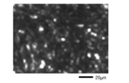
- the average pore diameter can be measured by the following procedure.
- a stereoscopic microscope is used to irradiate transmitted illumination and take a photograph of the surface of the fiber structure (a2) magnified 10 times.
- image analysis software 50 or more bright spots transmitting light are extracted from the micrograph, and the area of each bright spot is measured.
- the diameter calculated as the area of a perfect circle is the pore diameter of the bright spot, and the average value of the pore diameters of 50 or more bright spots is the average pore diameter.
- the thickness of the dense fiber structure (a2) is preferably 1500 ⁇ m or less, more preferably 1000 ⁇ m or less, even more preferably 500 ⁇ m or less, and particularly preferably 300 ⁇ m or less. Further, the thickness of the dense fiber structure (a2) is preferably 50 ⁇ m or more, and preferably 100 ⁇ m or more. A thickness of 50 to 1500 ⁇ m is preferable because supply of oxygen, etc. to cells is unlikely to be inhibited.
- the basis weight of the dense fiber structure (a2) is preferably 3 to 300 g/m 2 , more preferably 10 to 100 g/m 2 . It is preferable that the basis weight is within the above range because it is possible to achieve the above-mentioned suitable average pore diameter and also to achieve the above-mentioned suitable thickness.
- the porosity of the dense fiber structure (a2) is preferably less than 90%, more preferably 87% or less, even more preferably 85% or less, particularly preferably 80% or less. . Further, it is preferably 30% or more, more preferably 50% or more, even more preferably 60% or more, and particularly preferably 70% or more. It is preferable that the voids between the fibers in the dense fiber structure (a2) are within the above range, since this tends to have an excellent function of preventing cells or cell clusters from deviating. Further, for example, the porosity of the dense fiber structure (a2) is preferably 30.0 to 89.9%, more preferably 50.0 to 87.0%, and more preferably 60.0 to 85. It is more preferably 0%, and particularly preferably 70.0 to 80.0%.
- the area of the dense fiber structure (a2) is not particularly limited, but is preferably 1.0 to 400 cm 2 , more preferably 1.0 to 200 cm 2 , and even more preferably 1.5 to 150 cm 2 .
- the area of the dense fiber structure (a2) is preferably larger than the fiber structure (a1) to the extent that it can cover the fiber structure (a1).
- the method for producing the dense fiber structure (a2) is not particularly limited, but a melt blown method is preferably used to achieve a suitable average pore diameter. Further, the surface of the dense fiber structure (a2) may be calendered.
- the number of cells retained in the cell trapping layer (A) is not particularly limited, but is preferably 1 ⁇ 10 5 to 1 ⁇ 10 7 cells/cm 3 , and 1 ⁇ 10 6 to 1 ⁇ 10 7 cells/cm 3 . More preferred.
- the immunoisolation device of the present invention includes an immunoisolation layer (B) covering the cell trapping layer (A).
- the immunoisolation layer (B) preferably covers the entire surface of the cell trapping layer (A) from the viewpoint of obtaining a sufficient immunoisolation effect. From the same point of view, it is preferable that the immunoisolation layer (B) has no holes such as pinholes penetrating the membrane. More preferably, the immunoisolation layer (B) is a multilayer immunoisolation layer (B') comprising a porous membrane (b1) or a fibrous structure (b2) and a hydrogel (b3).
- the porous membrane (b1) constituting the immunoisolation layer (B) is a membrane having a plurality of pores.
- the porous membrane can be confirmed by a scanning electron microscope (SEM) image or a transmission electron microscope (TEM) image of a cross section of the membrane.
- the thickness of the porous membrane (b1) is not particularly limited, but is preferably 300 ⁇ m or less, more preferably 15 ⁇ m to 290 ⁇ m, and more preferably 30 ⁇ m to 150 ⁇ m. When the thickness is within the above range, the strength of the immunoisolation layer (B) is maintained and the supply of oxygen and the like to the cells is not easily inhibited, which is preferable.
- the average pore diameter of the porous membrane (b1) is not particularly limited, but is preferably 0.01 ⁇ m to 10 ⁇ m, more preferably 0.01 ⁇ m to 5 ⁇ m, and even more preferably 0.01 to 3 ⁇ m.
- the average pore diameter can be determined from SEM or TEM images. For example, the surface of a porous membrane is observed using a SEM, and 50 pores are arbitrarily selected from among the pores formed on the surface. The major diameter of each hole is measured, and the average value of the 50 major diameters is derived to be the average pore diameter.
- the maximum pore diameter of the porous membrane (b1) is not particularly limited, but is preferably 0.01 ⁇ m to 10 ⁇ m, more preferably 0.01 ⁇ m to 5 ⁇ m, and even more preferably 0.01 ⁇ m to 4 ⁇ m. If the maximum pore size is within the above range, it will suppress the entry of immune response cells and humoral factors of the immune system into the device, and will also suppress the intrusion of immune response cells and humoral factors of the immune system into the device, as well as prevent nutrients such as amino acids, vitamins, inorganic salts, carbon sources such as glucose, and oxygen. , carbon dioxide, cytokines, hormones, insulin, and other physiologically active substances can be sufficiently permeated.
- the maximum pore diameter can be determined from a SEM image or a TEM image.
- the surface of a porous membrane is observed using a SEM, and 50 pores are arbitrarily selected from among the pores formed on the surface.
- the major diameter of each hole is measured, and the maximum value among the 50 major diameters is defined as the maximum hole diameter.
- the porous membrane (b1) needs to have the function of suppressing infiltration of cells from the recipient as well as preventing leakage of the transplanted cells, so the average pore diameter or maximum pore diameter is smaller than the cell diameter.
- the thickness is preferably 5 ⁇ m or less.
- the porous membrane (b1) contains a polymer and is substantially composed of the polymer.
- polymers include thermoplastic or thermoset polymers. Specific examples of polymers include ethylene vinyl alcohol copolymer, polysulfone, cellulose acetate such as cellulose acetate, nitrocellulose, sulfonated polysulfone, polyethersulfone, polyacrylonitrile, styrene-acrylonitrile copolymer, styrene-butadiene copolymer, polyvinyl Examples include alcohol, polycarbonate, organosiloxane-polycarbonate copolymer, polyester carbonate, organopolysiloxane, polyphenylene oxide, polyamide, polyimide, polyamideimide, polybenzimidazole, polytetrafluoroethylene (PTFE), and the like.
- PTFE polytetrafluoroethylene
- the polymer constituting the porous membrane may include hydrophilic polymers such as polyvinylpyrrolidone, hydroxypropylcellulose, hydroxyethylcellulose, and polyethylene glycol. Biocompatibility can be improved by combining hydrophilic and hydrophobic polymers.
- the polymer forming the porous membrane (b1) is preferably a material with excellent biocompatibility that does not easily cause adhesion with the surrounding tissue of the recipient, inflammation, etc.
- the porous membrane (b1) preferably contains at least one member selected from the group consisting of ethylene vinyl alcohol copolymer and cellulose acetate, and more preferably contains ethylene vinyl alcohol copolymer.
- the ethylene vinyl alcohol copolymer those described in the fiber structure (a1) can be preferably used.
- the porous membrane (b1) may be composed of one type of porous membrane, or may be a stack of two or more types of porous membranes.
- the porous membrane (b1) includes two or more porous membranes, those porous membranes may be directly laminated, or a hydrogel or fibrous structure may be interposed between the two porous membranes.
- the porous membrane (b1) is preferably formed as a single layer from one composition, and in one embodiment, it is preferable that the porous membrane (b1) is not a laminated structure of multiple layers.
- the fibrous structure (b2) constituting the immunoisolation layer (B) includes nonwoven fabrics, woven fabrics, and knitted fabrics, with nonwoven fabrics being preferred.
- a fibrous structure is one in which fibers are bonded or intertwined by thermal, mechanical, or chemical action.
- the basis weight (weight per unit area) can be adjusted by adjusting the fiber diameter and/or the amount of fibers, and as a result, it is possible to control not only the strength but also the transmittance, filterability, etc.
- the basis weight of the fiber structure (b2) is preferably 10 to 100 g/m 2 .
- the thickness of the fiber structure (b2) is preferably 300 ⁇ m or less, and preferably as thin as possible, 200 ⁇ m or less, in consideration of the diffusion efficiency of the physiologically active substance from the implanted object.
- the lower limit of the thickness of the fiber structure (b2) is not particularly limited, for example, it is preferably 50 ⁇ m or more, more preferably 100 ⁇ m or more.
- the fiber materials of the fiber structure (b2) include gelatin, collagen, chitin, chitosan, fibronectin, dextran, cellulose, polyethylene (PE), polypropylene (PP), polyurethane, polyamide, polyester, polyvinyl alcohol (PVA), PVA modified with monomers such as ethylene vinyl alcohol copolymer, polylactic acid, polyglycolic acid, polylactic acid-polyglycolic acid copolymer, methacrylic modified PVA, acrylic modified PVA, polycaprolactone, polyglycerol sebacic acid, poly Examples thereof include hydroxyalkanoic acid, polybutylene succinate, polymlylene carbonate, cellulose diacetate, cellulose triacetate, cellulose acetate such as methyl cellulose, propyl cellulose, benzyl cellulose, and carboxymethyl cellulose, fibroin, and silk.
- PVA polyvinyl alcohol
- PVA PVA modified with monomers such as ethylene vinyl alcohol copolymer
- the fibrous material of the fibrous structure is preferably biocompatible.
- the fiber structure (b2) preferably contains at least one selected from the group consisting of ethylene vinyl alcohol copolymer and cellulose acetate, and more preferably contains ethylene vinyl alcohol copolymer.
- the ethylene vinyl alcohol copolymer those described in the fiber structure (a1) can be preferably used.
- the surface of the fiber structure is smoothed by thermal, mechanical or chemical treatment.
- Hydrosols for producing the hydrogel (b3) constituting the immunoisolation layer (B) include, for example, a sol that gels in the presence of metal ions to form a hydrogel, and a sol that gels in response to pH to form a hydrogel. Examples include sols that form gels and sols that form hydrogels in response to light. Metal ions and pH are examples of chemical effects. In order to gel these hydrosols, depending on the properties of the gel used, it is necessary to bring metal ions into contact, adjust the temperature to gelling conditions, adjust pH to gelling conditions, and apply light to gelling conditions. Operations such as irradiation or applying a magnetic field for gelation conditions may be performed.
- Hydrogels that gel in the presence of metal ions include alginate gels that gel in the presence of divalent or trivalent metal ions, preferably alkaline earth metal ions such as calcium ions and magnesium ions; Examples include carrageenan gel that gels in the presence of potassium ions; and acrylic acid-based synthetic gels that gel in the presence of sodium ions.
- pH-responsive hydrogel examples include alginate gel, chitosan gel, carboxymethylcellulose gel, acrylic acid-based synthetic gel, and the like.
- photoresponsive hydrogels include synthetic gels that combine azobenzene and cyclodextrin in the skeleton, gels that consist of supramolecular molecules with fumaric acid amide spacers, gels that are crosslinked or bonded via nitrobenzyl groups, and modified polyvinyl alcohol. Examples include gels consisting of.
- modified polyvinyl alcohol include (meth)acryloyl group-modified polyvinyl alcohol. A (meth)acryloyl group can be introduced by subjecting a hydroxyl group, which is a side chain of polyvinyl alcohol, to an esterification reaction or transesterification reaction with an ethylenically unsaturated group-containing compound in the presence of a base.
- Examples of the ethylenically unsaturated group-containing compound include (meth)acrylic acid or derivatives thereof such as (meth)acrylic acid, (meth)acrylic anhydride, (meth)acrylic acid halide, and (meth)acrylic acid ester. can be mentioned.
- Preferred examples of the hydrogel (b3) include polyvinyl alcohol, polyethylene glycol, chitosan, alginate, and the like.
- the hydrogel (b3) preferably contains at least one member selected from the group consisting of polyvinyl alcohol and polyethylene glycol, and more preferably contains polyvinyl alcohol.
- Polyvinyl alcohol can be produced, for example, by saponifying a polyvinyl ester obtained by polymerizing a vinyl ester monomer and converting the ester groups in the polyvinyl ester into hydroxyl groups.
- vinyl ester monomer examples include vinyl formate, vinyl acetate, vinyl propionate, vinyl n-butyrate, vinyl isobutyrate, vinyl pivalate, vinyl versatate, vinyl caproate, vinyl caprylate, and vinyl caprate. , aliphatic vinyl esters such as vinyl laurate, vinyl myristate, vinyl palmitate, vinyl stearate, and vinyl oleate; and aromatic vinyl esters such as vinyl benzoate. One type of these may be used alone or two or more types may be used in combination.
- the polyvinyl ester is preferably polyvinyl acetate obtained by polymerizing vinyl acetate.
- the polyvinyl ester may optionally contain a structural unit derived from a monomer other than the vinyl ester monomer, within a range that does not impair the effects of the present invention.
- the other monomers include ⁇ -olefins such as ethylene, propylene, n-butene, and isobutylene; acrylic acid or its salts; methyl acrylate, ethyl acrylate, n-propyl acrylate, and i-acrylate.
- Acrylic acid alkyl ester compounds such as propyl, n-butyl acrylate, i-butyl acrylate, t-butyl acrylate, 2-ethylhexyl acrylate, dodecyl acrylate, octadecyl acrylate; Methacrylic acid or its salt; Methyl methacrylate , ethyl methacrylate, n-propyl methacrylate, i-propyl methacrylate, n-butyl methacrylate, i-butyl methacrylate, t-butyl methacrylate, 2-ethylhexyl methacrylate, dodecyl methacrylate, octadecyl methacrylate, etc.
- Methacrylic acid alkyl ester compound acrylamide, N-methylacrylamide, N-ethylacrylamide, N,N-dimethylacrylamide, diacetone acrylamide, acrylamide propane sulfonic acid or its salt, acrylamide propyl dimethylamine or its salt or quaternary salt, N - Acrylamide derivatives such as methylolacrylamide or its derivatives; methacrylamide, N-methylmethacrylamide, N-ethylmethacrylamide, methacrylamidepropanesulfonic acid or its salt, methacrylamidepropyldimethylamine or its salt or quaternary salt, N- Methacrylamide derivatives such as methylolmethacrylamide or its derivatives; N-vinylamide derivatives such as N-vinylformamide and N-vinylacetamide; methyl vinyl ether, ethyl vinyl ether, n-propyl vinyl ether, i-propyl vinyl ether, n-butyl vinyl ether
- the average degree of polymerization of polyvinyl alcohol is preferably 300 to 10,000, more preferably 500 to 5,000, even more preferably 1,000 to 5,000, even more preferably 1,500 to 5,000, and particularly preferably 2,000 to 5,000. If it is within the above range, it is preferable from the viewpoint of material permeability and multi-layer handling property.
- the average degree of polymerization of polyvinyl alcohol in this specification refers to the average degree of polymerization measured according to JIS K 6726:1994. Specifically, it can be determined from the intrinsic viscosity measured in water at 30° C. after saponifying and purifying the raw material PVA.
- the degree of saponification of polyvinyl alcohol is preferably 50 mol% or more, more preferably 60 mol% or more, and still more preferably 65 mol% or more.
- the saponification degree of polyvinyl alcohol is preferably 99.9 mol% or less, more preferably 99.5 mol% or less. , more preferably 99.0 mol% or less.
- the degree of saponification of polyvinyl alcohol is defined as the number of vinyl alcohol units relative to the total number of moles of structural units (for example, vinyl acetate units) and vinyl alcohol units that can be converted into vinyl alcohol units by saponification in the raw material PVA. It means the proportion (mol%) occupied by the number of moles, and can be measured according to JIS K6726:1994.
- the thickness of the hydrogel (b3) is not particularly limited, but is preferably 1 to 300 ⁇ m, more preferably 5 to 200 ⁇ m, and even more preferably 10 to 100 ⁇ m.
- Hydrogel (b3) can adjust the permeability, strength, etc. of nutritional substances such as glucose, physiologically active substances such as insulin, immune system humoral factors, etc. by crosslinking.
- the gel strength of the hydrogel (b3) is preferably 20 to 300 kPa, more preferably 50 to 200 kPa.
- the gel strength can be measured by the following procedure using a tensile tester. First, a hydrosol solution is poured between glass plates sandwiching a 1 mm thick spacer and treated under predetermined gelling conditions to obtain a 1 mm thick gel sheet. A test piece is cut out from this gel sheet using a dumbbell cutter according to JIS K-6251-3 standard. The test piece is set in a tensile tester (Model 5566) manufactured by Instron, and the breaking stress and breaking strain are measured while acquiring image data, and the stress at the time when the test piece breaks is defined as gel strength.
- a tensile tester Model 5566
- the immunoisolation layer (B) is a porous membrane (b1) containing at least one member selected from the group consisting of ethylene vinyl alcohol copolymer and cellulose acetate, or the porous membrane (b1) containing at least one member selected from the group consisting of ethylene vinyl alcohol copolymer and cellulose acetate. It is preferable that the fiber structure (b2) contains at least one selected from the following. Furthermore, the immunoisolation layer (B) has a multilayer structure that includes, in addition to the porous membrane (b1) or the fibrous structure (b2), a layer other than the porous membrane (b1) and the fibrous structure (b2). You may do so.
- Hydrogel (b3) is preferable as the layer other than the porous membrane (b1) and the fibrous structure (b2).
- an immunoisolation layer containing a porous membrane (b1) or a fibrous structure (b2) and a hydrogel (b3) may be referred to as a multilayer immunoisolation layer (B').
- the multilayering with the hydrogel (b3) makes the immunoisolation property stronger and also improves the strength as the immunoisolation layer (B). Balancing the permeability and immunoisolation properties can be adjusted by adjusting the pore diameter of the porous membrane and the gel strength and/or crosslinking degree of the hydrogel (b3).
- the porous membrane (b1) can suppress cell infiltration and cell leakage, but does not suppress the permeability of necessary physiologically active substances, and does not suppress the infiltration of immune system humoral factors such as IgG antibodies. It's not easy. Therefore, by adjusting the gel strength or crosslinking density of the hydrogel (b3) multilayered on the porous membrane (b1), it is possible to prevent the immune system such as IgG antibodies from suppressing the permeability of physiologically active substances. It becomes possible to suppress infiltration of humoral factors.
- the monolayer of the fibrous structure (b2) not only suppresses cell infiltration and cell leakage, but also suppresses the infiltration of immune system humoral factors such as IgG antibodies without suppressing the permeability of necessary physiologically active substances. It's not easy. Therefore, by adjusting the gel strength or crosslinking density of the hydrogel (b3) multi-layered on the fibrous structure (b2), we can prevent cell infiltration and cell leakage without suppressing the permeability of physiologically active substances. Therefore, it becomes possible to suppress the infiltration of immune system humoral factors such as IgG antibodies.
- the porous membrane (b1), the fibrous structure (b2), and the hydrogel (b3) each form a layer, and the boundaries between them may be clearly separated, or the boundaries between the two layers may not be clear.
- two or three types may be integrated to form one layer.
- a fibrous structure (b2) and a hydrogel (b3) the fibrous structure and the hydrogel may be clearly separated, and the fibrous structure and the hydrogel may have a fibrous structure between the fibrous structure and the hydrogel.
- the fiber structure and the hydrogel may have a mixed layer, or the fiber structure and the hydrogel may be completely integrated to form one layer.
- a fibrous structure (b2) and a porous membrane (b1) the fibrous structure and the porous membrane may be clearly separated, and the fibrous structure and the porous membrane may have a fiber structure between them. It may have a layer in which the structure and the porous membrane are mixed, or the fiber structure and the porous membrane may be completely integrated to form one layer.
- a hydrogel (b3) and a porous membrane (b1) the hydrogel and the porous membrane may be clearly separated, and the hydrogel and the porous membrane are placed between the hydrogel and the porous membrane. It may have a layer in which a porous membrane is mixed, or a hydrogel and a porous membrane may be completely integrated to form one layer.
- a particularly preferred immunoisolation device of the present invention is composed of any one of the following three types of multilayer structures (i) to (iii).
- the porous membrane (b1) is coated with or impregnated with the hydrogel (b3).
- the fibrous structure (b2) is coated with or impregnated with the hydrogel (b3).
- a porous membrane (b1) is formed using the fibrous structure (b2) as a base material, and a hydrogel (b3) is further applied or impregnated.
- the immunoisolation layer (B) When the immunoisolation layer (B) has a plurality of layers, these layers may be adhered by adhesive, heat, pressure, etc., and when adjacent layers are composed of highly compatible materials, Adhesion can be achieved by sequentially forming layers.
- the porous membrane (b1) is used as a base material, a hydrosol solution is applied directly to the porous membrane, and the membrane is hydrogelated by heat, temperature, light, or chemical action to form a multilayer structure.
- a hydrosol solution is applied directly to the fibrous structure, and the fiber structure is formed into a multilayer by hydrogel formation by heat, temperature, light, or chemical action.
- porous membrane (b1) By using a fibrous structure (b2) such as a nonwoven fabric coated with a hydrogel (b3) in place of the porous membrane (b1), the porous membrane (b1) can be ), it is possible to construct a highly strong immunoisolation layer (B) that has higher substance permeability than that of (B).
- the solid content concentration of the hydrosol solution is preferably 3 to 15% by mass, more preferably 3 to 10% by mass, even more preferably 3 to 8% by mass, and even more preferably 3 to 5% by mass. It is particularly preferable. If it is within the above range, it is possible to maintain permeability of substances such as glucose and insulin while suppressing permeation of IgG and the like, which are humoral factors of the immune system.
- the hydrogel (b3) is used as a base material, and a polymer solution, which is a raw material for the porous membrane (b1), is directly applied onto the base material, and phase separation, which is a phase transition phenomenon, occurs to form the porous membrane (b1). ) can be solidified to form a porous membrane (b1).
- a polymer solution which is a raw material for the porous membrane (b1)
- phase separation which is a phase transition phenomenon
- a highly durable fibrous structure (b2) is used as a base material, and a hydrogel (b3) is formed on the fibrous structure (b2), or a porous structure is formed on the fibrous structure (b2).
- a plasma membrane (b1) and a hydrogel (b3) it is possible to maintain the immunoisolation effect while improving the diffusion efficiency of physiologically active substances.
- the device can be made thinner and more durable due to improved strength. becomes possible.
- the thickness of the immunoisolation layer (B) is not particularly limited, but is preferably 10 ⁇ m or more and 500 ⁇ m or less, more preferably 300 ⁇ m or less, even more preferably 200 ⁇ m or less, even more preferably 170 ⁇ m or less, and especially Preferably it is 150 ⁇ m or less.
- the immunoisolation layer (B) is a multilayer immunoisolation layer (B')
- it is preferably within the above range.
- the thickness of the multilayer immunoisolation layer (B') is preferably 500 ⁇ m or less, more preferably 300 ⁇ m or less, and even more preferably 100 ⁇ m or less, considering the diffusion efficiency of the physiologically active substance from the transplanted object.
- the area of the immunoisolation layer (B) is not particularly limited, but is preferably 1.0 to 400 cm 2 , more preferably 1.0 to 200 cm 2 , even more preferably 1.5 to 150 cm 2 .
- the area of the immunoisolation layer (B) is preferably equal to or larger than that of the cell trapping layer (A) so that it can cover the cell trapping layer (A).
- the outermost layer of the immunoisolation layer (B) is preferably biocompatible in order to prevent it from being recognized as a foreign substance.
- the immunoisolation layer (B) is required to have the permeability necessary to allow sufficient oxygen and nutrients to pass through to the recipient body therein.
- the outermost layer of the immunoisolation layer (B) may be a porous membrane (b1), a fibrous structure (b2), or a hydrogel (b3), or a mixture of two or three of these. There may be. Further, the innermost layer of the immunoisolation layer (B) may be a porous membrane (b1), a fibrous structure (b2), or a hydrogel (b3), or a mixture of two or three of these. It may be something.
- the outermost layer of the immunoisolation layer (B) refers to the layer that constitutes the outer part of the immunoisolation device of the present invention, that is, the tissue surrounding the transplant site (host).
- the innermost layer of the immunoisolation layer (B) refers to the layer in contact with the cell trapping layer (A) of the immunoisolation device of the present invention (inner portion) of the immunoisolation layer (B). means.
- the porous membrane (b1) is preferably a material with better biocompatibility than the hydrogel (b3), and the hydrogel (b3) It also plays a role in preventing adhesion with recipient transplanted tissue and the occurrence of inflammation.
- the fibrous structure (b2) is preferably a material with better biocompatibility than the hydrogel (b3); It is also desirable to smooth the surface of the fiber structure (b2), which is the outermost layer, by thermal, mechanical or chemical treatment, since it also plays the role of preventing adhesion with the recipient tissue and the occurrence of inflammation.
- the amount of permeation of glucose, insulin, humoral factors of the immune system, etc. through the immunoisolation layer (B) is determined by sandwiching the immunoisolation layer between two glass chambers of the same capacity, and placing a sample of insulin, etc. at a known concentration in chamber a.
- the amount of insulin, etc. contained in the solution sampled from chamber b can be measured by ELISA etc. after a certain period of time by pouring water into chamber b and stirring at 37°C ( Figure 9). . Note that the liquid volumes in chambers a and b are adjusted so that they are equal when the sample solution is poured into chamber a.
- the permeability of glucose, insulin, immune system humoral factors, etc. of the immune isolation layer (B) is determined by the concentration at which the permeation amount of each substance into chamber b after 20 hours, measured by the above method, reaches equilibrium, that is, the chamber
- the value is expressed as a percentage of half of the concentration added to a.
- the insulin and glucose permeability of the immunoisolation layer (B) is preferably 50% or more, more preferably 90% or more, and even more preferably 95% or more.
- the permeability of the immune system humoral factors of the immunoisolation layer (B) is preferably 30% or less, more preferably 10% or less.
- the permeability of each substance can be controlled by the pore diameter of the porous membrane (b1), the fiber basis weight of the fibrous structure (b2), or the strength and degree of crosslinking of the hydrogel (b3).
- the pore size of the porous membrane (b1) is smaller than the size that does not penetrate cells, and the hydrogel (b3) does not suppress the permeation of physiologically active substances and is suitable for immune response factors such as cells and antibodies. It is desirable to be able to suppress the transmission of.
- Immune responsive cells include macrophages, cytotoxic T cells, natural killer cells, dendritic cells, helper T cells, etc., and immune system humoral factors include antibodies, complement, cytokines, etc.
- the immunoisolation device is bag-shaped, tubular, cylindrical, prismatic, spherical, cubic, rectangular, sheet-shaped, or hollow fiber-shaped, and has a cell-trapping layer (A) enclosed therein. do.
- a transplant target is introduced into the cell trapping layer (A).
- the object to be transplanted may be cells, cell aggregates, cell sheets, grafts, etc., and physiologically active substances other than cells such as enzymes, hormones, cytokines, drugs, etc. can also be used.
- Preferred cells, cell masses or grafts are those that release bioactive substances out of the immunoisolation device. That is, in a preferred embodiment, the cells, cell masses, or grafts contain physiologically active substance producing cells.
- a suspension of the transplanted material is uniformly injected and seeded into the fibrous structure (a1) using a pipette or the like.
- a dense fibrous structure (a2) of a different specification with smaller voids is used to cover the surrounding area, so that the transplanted object can be removed from the cell trapping layer. It is possible to prevent deviation of objects. That is, it is preferable that the porosity of the dense fiber structure (a2) is smaller than the porosity of the fiber structure (a1).
- the peripheral part of the device is sealed by heat fusion and molded into a pouch shape.
- Isolation devices may also be created.
- an opening is provided in a device prepared in advance with the immunoisolation layer (B), the cell trapping layer (A) is inserted therein, and the opening is then closed by heat fusion. Invasion of immune response cells and humoral factors of the immune system may be inhibited. Since oxygen, nutrients, etc. can permeate through the immunoisolation layer (B) other than the openings, the openings can be closed to suppress the permeation of substances, including nutrients.
- heat fusion can be carried out by sandwiching a resin between the immunoisolation layers (B) (multilayer immunoisolation layers (B')).
- the innermost layers of the upper and lower immunoisolation layers (B) in an immunoisolation device are both made into hydrogels by sandwiching and heat-sealing the resin (in the upper and lower immunoisolation layers (B), the hydrogels face each other). It can also be easily heat-sealed even if the
- the resin used for heat fusion is not particularly limited, but is preferably at least one selected from the group consisting of ethylene vinyl alcohol copolymer and cellulose acetate, more preferably ethylene vinyl alcohol copolymer. preferable.
- the dense fiber structure (a2) can be sandwiched between the immunoisolation layers (B) and heat-sealed.
- the recipient with decreased function is removed, a new functional recipient is introduced, this operation is repeated, and the immunoisolation device is repeatedly inserted into the recipient. It may be used for introduction and the immunoisolation device may be removed with the recipient.
- the immunoisolation device of the present invention has sufficient strength, exists stably in the recipient's body, and can suppress the invasion of immunocompetent cells into the cell trapping layer (A). Infiltration of internal implants into the recipient body can also be inhibited at the same time. Therefore, even those derived from iPS cells, which are concerned about cancerous transformation of the transplanted object, can be used with confidence.
- the immunoisolation device of the present invention preferably has shape retention to have sufficient strength in vivo.
- a fibrous structure (a1) used as a cell trapping layer (A), a dense fibrous structure (a2) used as an immunoisolation layer (B), and a porous membrane ( b1), the fibrous structure (b2), and the hydrogel (b3) are all desirably materials with excellent safety and biocompatibility.
- the immunoisolation layer (B) be made of a material with excellent biocompatibility.
- the material with excellent biocompatibility serve as the outermost contact surface that contacts the transplant side, that is, the recipient's transplant site. Examples of materials with excellent biocompatibility include ethylene vinyl alcohol copolymer.
- the thickness of the immunoisolation device of the present invention varies depending on the recipient tissue, the transplanted object, etc., and is not particularly limited, but is preferably 400 to 2000 ⁇ m. Further, the area of the immunoisolation device of the present invention also varies depending on the recipient tissue, the transplanted object, etc., and is not particularly limited, but is preferably 1.0 to 200 cm 2 .
- the device schematic diagram shows the immunoisolation layer (B) formed into a bag shape (FIG. 1) or a tube shape (FIG. 2).
- the bag-like device (Fig. 1) consists of a multi-layered immunoisolation layer (B) (x1 and x2) shown below, separated by a certain distance (x4) in order to secure a space for enclosing the cell-trapping layer (A). They are separated and welded (x3) using heat, ultrasonic waves, high frequency waves, electron beams, or the like. A spacer may be provided to ensure a certain distance (x4).
- the tubular device (Fig. 2) is composed of each immunoisolation layer (B) (y1, y2, y3) formed into a tubular shape, and the cell trapping layer (A) is enclosed in the tubular interior (y4). It is molded by welding and sealing both ends using heat, ultrasonic waves, high frequency waves, electron beams, etc.
- FIGS. 3A and 3B show conceptual diagrams of an immunoisolation device in one embodiment of the present invention.
- the outermost layer of the immunoisolation layer (B) is in contact with the transplant site, and the innermost layer is in contact with the cell trapping layer (A).
- the immunoisolation device has a bag-like or tubular shape, and a cell trapping layer in which a transplanted object is dispersed is sealed inside the device.
- the cell trapping layer (A) is a material in which transplant objects such as cells and cell aggregates are uniformly dispersed and fixed in the fiber structures (a1) (5) inside the cell trapping layer (A). show.
- the fiber structures (a1) (5) preferably contain at least one selected from the group consisting of ethylene vinyl alcohol copolymer and cellulose acetate, which have excellent biocompatibility, and include cell scaffolds such as collagen fibers. It may be a material.
- Both of the fiber structures (a1) and (5) can be sterilized.
- the fibrous structure (a1) (5) may be present in the cell trapping layer (A) surrounded by the immunoisolation layer (B) before the introduction of the transplant object, and is composed of the immunoisolation layer (B).
- the transplanted object (3) and the fibrous structures (a1) and (5) may be introduced later into the immunoisolation device as a cell trapping layer (A).
- polyvinyl alcohol or polyethylene glycol hydrogel particles, block-shaped structures, etc. are suspended with the transplanted material. This may prevent aggregation and association of cells or cell clusters that are transplanted objects.
- FIG. 4 shows a conceptual diagram of the cell trapping layer (A).
- the cell trapping layer (A) includes two types, a fibrous structure (a1) and a dense fibrous structure (a2), in which the fibrous structure (a1) captures the transplanted object and the captured fibers of the transplanted object.
- a structure in which the periphery of the fiber structure (a1) is covered with a dense fiber structure (a2) having smaller voids.
- FIG. 5 is a transmitted light microscopic image of the dense fiber structure (a2). Such an image is acquired, and the area of each bright spot through which light is transmitted is measured using image analysis software. The diameter calculated as the area of a perfect circle is the pore diameter of the bright spot, and the average value of the pore diameters of 50 or more bright spots is the average pore diameter.
- the immunoisolation layer (B) shown in FIGS. 6 and 7 is composed of a combination of multiple materials shown below.
- the outermost layer contacts the transplant site tissue of the recipient, and the innermost layer contacts the cell trapping layer (A).
- These immunoisolation layers (B) are formed into a bag shape ( Figure 1) or a tube shape ( Figure 2), and a cell trapping layer (A) is formed into a bag shape ( Figure 1) or a tube shape ( Figure 2), and the cells and/or cell mass to be transplanted are fixed inside. encapsulated and used as an immunoisolation device.
- Figure 6 shows multilayering of the porous membrane (b1) (6) and the hydrogel (b3) (8).
- the hydrogel (b3) (8) is impregnated (7) into a porous membrane (b1) (6), the outermost layer surface (9) is composed of the porous membrane (b1), and the innermost layer surface (10) is composed of hydrogel (b3).
- Figure 7 shows multilayering of the fibrous structure (b2) (11) and the hydrogel (b3) (12).
- the hydrogel (b3) (12) is formed by coating or impregnating the fiber structure (b2) (11), the outermost layer surface (13) is composed of the fiber structure (b2), and the innermost layer surface (14) ) is composed of hydrogel (b3).
- a porous membrane formed using ethylene vinyl alcohol copolymer (hereinafter referred to as EVOH) and a hydrogel whose main component is methacryloyl group-modified polyvinyl alcohol (hereinafter referred to as MA-PVA) were multilayered in the following procedure.
- EVOH EVOH
- F101A EVOH
- MA-PVA a porous membrane (average pore diameter 1.8 ⁇ m, maximum pore diameter 3.4 ⁇ m, thickness 100 ⁇ m) was formed by a polymer phase separation reaction. Created.
- MA-PVA aqueous solution of MA-PVA (average polymerization degree 1700, saponification degree 98.0-99.0 mol%, methacryloyl group modification rate 1.2 mol%, hereinafter referred to as MA-PVA) at a concentration of 10% by mass.
- phenyl (2,4,6-trimethylbenzoyl)phosphinate lithium salt which is a water-soluble photoradical polymerization initiator, was added and dissolved to a concentration of 0.1% by mass to prepare a sol.
- This sol was coated onto a PET film to a thickness of 50 ⁇ m using a bar coater.
- a porous membrane was placed on top of the sol, and the sol and porous membrane were brought into close contact with each other using a laminator.
- a hydrogel is formed on the porous membrane by irradiating it with 365 nm light at an intensity of 15 mW/ cm2 for 3 minutes, forming a multilayer immunoisolation layer (B').
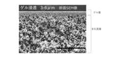
- FIG. 8 shows an SEM image of the cross section of the obtained multilayer immunoisolation layer (B'). It was found that the hydrogel penetrated into the porous membrane to a depth of about 3 to 6 ⁇ m.
- ⁇ Matter permeability test> The permeability of glucose, insulin, and IgG was measured for the porous membrane used in Production Example 1 and the multilayer immunoisolation layer (B') obtained in Production Example 1 or 2 using the following procedure.
- a porous membrane or multilayer immunoisolation layer is sandwiched between chambers a and b (Fig. 9), and chamber a is charged with insulin (30 U/L), glucose (5 mg/mL), and IgG (0.5 ⁇ g). /mL) was prepared. Water (65 mL) was placed in chamber b.
- the fibers were subjected to a steam jet process, and the fibers were bonded using heat and jets of steam to obtain a nonwoven fabric sheet with a basis weight of 50 g/m 2 and a thickness of 1 mm.
- the nonwoven fabric sheet was cut out into a circular shape using a punch with a diameter of 15 mm to produce a fibrous structure (a1) for cell trapping (porosity: 96%).
- the porosity was calculated by the following formula from the basis weight C (g/m 2 ) of the fibrous structure, the thickness D (cm), and the average specific gravity E (g/cm 2 ) of the fibers.
- Porosity (%) 100 - ((C/D/E) x 10 -4 x 100)
- the melt-blown nonwoven fabric obtained after the treatment had a basis weight of 76.6 g/m 2 , a thickness of 0.24 mm, and a porosity of 73%.
- the porosity was calculated by the following formula from the area weight C (g/m 2 ), thickness D (cm), and average specific gravity E (g/cm 2 ) of the dense fiber structure.
- Porosity (%) 100 - ((C/D/E) x 10 -4 x 100) (3)
- a 24 mm square piece was cut out of the melt-blown nonwoven fabric to produce a dense fiber structure (a2) (average pore diameter: 11 ⁇ m) for preventing cell escape.
- MIN6 mouse pancreatic islet-like cell line
- MIN6 was seeded at a density of 2.8 x 10 5 cells/cm 2 in a suspension cell culture flask (manufactured by Sumitomo Bakelite Co., Ltd.) containing DMEM medium, and cultured at 37°C for 7 days to form cells with a diameter of approximately 100-200 ⁇ m.
- a cell mass was prepared.
- 1 mL of cell suspension was collected from the flask and treated with 1 mL of trypsin-EDTA to disperse the cell mass into individual cells, and the cell density was measured using a hemocytometer. Based on the measured cell density, when cells were seeded in the following examples, the liquid volume was adjusted so that 5 x 10 5 cells were seeded on the fiber structure and used for the test.
- Example 1 Seeding of cells and encapsulation in an immunoisolation device (1)
- the multilayer immunoisolation layer (B') produced in Production Example 2 was cut into 24 mm square pieces and placed with the hydrogel side facing up.
- the dense fiber structure (a2) produced in Production Example 4 was placed on top of it, and the fiber structure (a1) produced in Production Example 3 was further placed on top of it in the center.
- the MIN6 cell mass suspension prepared in Production Example 5 50 ⁇ l of DMEM medium contains 5 ⁇ 10 5 cells was applied to the fiber structure (a1) using a micropipette from the top.
- the cells were seeded and allowed to stand for 30 seconds to infiltrate the cell mass suspension into the fiber structure (a1). (3) Place the dense fibrous structure (a2) produced in Production Example 4 on the fibrous structure (a1) seeded with cells, and then place the multilayer immunoisolation layer (B') produced in Production Example 2, It was placed hydrogel side down. The four sides of the stacked immunoisolation layer (B') and dense fiber structure (a2) were welded together using a heat sealer (Clip Sealer Z-1 manufactured by Techno Impulse) to produce an immunoisolation device (FIG. 3B).
- a heat sealer Clip Sealer Z-1 manufactured by Techno Impulse
- Example 2 An immunoisolation device was produced in the same manner as in Example 1 except that the basis weight of the fiber structure (a1) was changed to 100 g/m 2 (porosity 92%). When the cell survival rate was measured in the same manner as in Example 1, it was 88%.
- Example 3 An immunoisolation device was produced in the same manner as in Example 1, except that the basis weight of the fiber structure (a1) was changed to 25 g/m 2 and the thickness was changed to 0.5 mm (porosity 96%). When the cell survival rate was measured in the same manner as in Example 1, it was found to be 103%.
- Example 4 Immunoisolation was carried out in the same manner as in Example 1, except that the basis weight of the dense fiber structure (a2) was changed to 22.3 g/m 2 and the thickness was changed to 0.12 mm (average pore diameter 23.5 ⁇ m, porosity 84%). The device was created. Cell viability was measured in the same manner as in Example 1 and found to be 96%.
- the cell mass could be captured without deviating from the cell capture layer (A).
- the fiber structure (a1) having an appropriate porosity can trap cell clusters while maintaining a high survival rate.
- the dense fibrous structure (a2) having an appropriate average pore diameter can prevent the cell mass from escaping from the fibrous structure (a1).
- the present invention relates to a transplant device used in cell transplant therapy, etc., and particularly to an immunoisolation device for protecting a transplant recipient from immune rejection.
- the immunoisolation device is primarily intended to be used as a regenerative medicine product for cell transplantation therapy, but it can also be applied to the transplantation of physiologically active substances other than cells, such as enzymes, hormones, and drugs.
Landscapes
- Health & Medical Sciences (AREA)
- Chemical & Material Sciences (AREA)
- General Health & Medical Sciences (AREA)
- Dispersion Chemistry (AREA)
- Analytical Chemistry (AREA)
- Hematology (AREA)
- Clinical Laboratory Science (AREA)
- Chemical Kinetics & Catalysis (AREA)
- Transplantation (AREA)
- Fluid Mechanics (AREA)
- Physics & Mathematics (AREA)
- Heart & Thoracic Surgery (AREA)
- Oral & Maxillofacial Surgery (AREA)
- Engineering & Computer Science (AREA)
- Biomedical Technology (AREA)
- Cardiology (AREA)
- Vascular Medicine (AREA)
- Life Sciences & Earth Sciences (AREA)
- Animal Behavior & Ethology (AREA)
- Public Health (AREA)
- Veterinary Medicine (AREA)
- Materials For Medical Uses (AREA)
Priority Applications (4)
| Application Number | Priority Date | Filing Date | Title |
|---|---|---|---|
| CN202380050671.6A CN119451707A (zh) | 2022-04-28 | 2023-04-27 | 免疫隔离装置 |
| JP2024518044A JPWO2023210765A1 (https=) | 2022-04-28 | 2023-04-27 | |
| EP23796500.9A EP4516329A1 (en) | 2022-04-28 | 2023-04-27 | Immunoisolation device |
| US18/859,610 US20250170572A1 (en) | 2022-04-28 | 2023-04-27 | Immunoisolation device |
Applications Claiming Priority (2)
| Application Number | Priority Date | Filing Date | Title |
|---|---|---|---|
| JP2022-075173 | 2022-04-28 | ||
| JP2022075173 | 2022-04-28 |
Publications (1)
| Publication Number | Publication Date |
|---|---|
| WO2023210765A1 true WO2023210765A1 (ja) | 2023-11-02 |
Family
ID=88518805
Family Applications (1)
| Application Number | Title | Priority Date | Filing Date |
|---|---|---|---|
| PCT/JP2023/016713 Ceased WO2023210765A1 (ja) | 2022-04-28 | 2023-04-27 | 免疫隔離デバイス |
Country Status (5)
| Country | Link |
|---|---|
| US (1) | US20250170572A1 (https=) |
| EP (1) | EP4516329A1 (https=) |
| JP (1) | JPWO2023210765A1 (https=) |
| CN (1) | CN119451707A (https=) |
| WO (1) | WO2023210765A1 (https=) |
Citations (4)
| Publication number | Priority date | Publication date | Assignee | Title |
|---|---|---|---|---|
| JPH09503941A (ja) * | 1993-10-08 | 1997-04-22 | ザ リージェンツ オブ ザ ユニバーシティ オブ ミシガン | 生体内または生体外での使用に適するバイオ人工腎臓の製造方法および構成 |
| JP2016524967A (ja) * | 2013-07-17 | 2016-08-22 | アンスティチュ ナショナル ドゥ ラ サンテ エ ドゥ ラ ルシェルシュ メディカル | 組織再生のための微細組織を用いて機能化された三次元スキャフォールド |
| JP2021500160A (ja) * | 2017-10-24 | 2021-01-07 | エムボディ インコーポレイテッド | 生体高分子足場移植片およびその生成のための方法 |
| JP2021003527A (ja) * | 2019-06-27 | 2021-01-14 | 株式会社日立製作所 | 生体親和性多孔質膜、バイオカプセルデバイスおよび生体親和性多孔質膜の製造方法 |
-
2023
- 2023-04-27 CN CN202380050671.6A patent/CN119451707A/zh active Pending
- 2023-04-27 US US18/859,610 patent/US20250170572A1/en active Pending
- 2023-04-27 WO PCT/JP2023/016713 patent/WO2023210765A1/ja not_active Ceased
- 2023-04-27 EP EP23796500.9A patent/EP4516329A1/en active Pending
- 2023-04-27 JP JP2024518044A patent/JPWO2023210765A1/ja active Pending
Patent Citations (4)
| Publication number | Priority date | Publication date | Assignee | Title |
|---|---|---|---|---|
| JPH09503941A (ja) * | 1993-10-08 | 1997-04-22 | ザ リージェンツ オブ ザ ユニバーシティ オブ ミシガン | 生体内または生体外での使用に適するバイオ人工腎臓の製造方法および構成 |
| JP2016524967A (ja) * | 2013-07-17 | 2016-08-22 | アンスティチュ ナショナル ドゥ ラ サンテ エ ドゥ ラ ルシェルシュ メディカル | 組織再生のための微細組織を用いて機能化された三次元スキャフォールド |
| JP2021500160A (ja) * | 2017-10-24 | 2021-01-07 | エムボディ インコーポレイテッド | 生体高分子足場移植片およびその生成のための方法 |
| JP2021003527A (ja) * | 2019-06-27 | 2021-01-14 | 株式会社日立製作所 | 生体親和性多孔質膜、バイオカプセルデバイスおよび生体親和性多孔質膜の製造方法 |
Also Published As
| Publication number | Publication date |
|---|---|
| JPWO2023210765A1 (https=) | 2023-11-02 |
| US20250170572A1 (en) | 2025-05-29 |
| EP4516329A1 (en) | 2025-03-05 |
| CN119451707A (zh) | 2025-02-14 |
Similar Documents
| Publication | Publication Date | Title |
|---|---|---|
| KR101685248B1 (ko) | 다층의 전기방사 섬유가 복합된 하이드로젤 | |
| AU2019352788B2 (en) | Membrane | |
| KR101186093B1 (ko) | 조직재생용 3차원 나노섬유 지지체 및 그 제조방법 | |
| US20170281826A1 (en) | Biohybrid for the Use Thereof in the Regeneration of Neural Tracts | |
| US20200360566A1 (en) | Immunoisolation device | |
| KR20160026899A (ko) | 세포 또는 조직 배양용 3차원 구조 | |
| US20230414832A1 (en) | Immunoisolation device | |
| WO2023210765A1 (ja) | 免疫隔離デバイス | |
| US20230302204A1 (en) | Hydrogel for cell embedding, immunoisolation device, and transplant material | |
| US20250276111A1 (en) | Immunoisolation device | |
| KR100431244B1 (ko) | 생분해성 고분자 다공성 지지체의 친수화 처리방법 | |
| JP7542401B2 (ja) | 血管新生を惹起することができる免疫隔離デバイス | |
| IL322348A (en) | Macroencapsulation devices containing immunomodulatory compounds | |
| JPWO2019004379A1 (ja) | 移植用チャンバーおよび移植用デバイス |
Legal Events
| Date | Code | Title | Description |
|---|---|---|---|
| 121 | Ep: the epo has been informed by wipo that ep was designated in this application |
Ref document number: 23796500 Country of ref document: EP Kind code of ref document: A1 |
|
| WWE | Wipo information: entry into national phase |
Ref document number: 2024518044 Country of ref document: JP |
|
| WWE | Wipo information: entry into national phase |
Ref document number: 18859610 Country of ref document: US |
|
| WWE | Wipo information: entry into national phase |
Ref document number: 2023796500 Country of ref document: EP |
|
| NENP | Non-entry into the national phase |
Ref country code: DE |
|
| ENP | Entry into the national phase |
Ref document number: 2023796500 Country of ref document: EP Effective date: 20241128 |
|
| WWE | Wipo information: entry into national phase |
Ref document number: 202380050671.6 Country of ref document: CN |
|
| WWP | Wipo information: published in national office |
Ref document number: 202380050671.6 Country of ref document: CN |
|
| WWP | Wipo information: published in national office |
Ref document number: 18859610 Country of ref document: US |