WO2023210538A1 - Belt and clothing - Google Patents
Belt and clothing Download PDFInfo
- Publication number
- WO2023210538A1 WO2023210538A1 PCT/JP2023/015974 JP2023015974W WO2023210538A1 WO 2023210538 A1 WO2023210538 A1 WO 2023210538A1 JP 2023015974 W JP2023015974 W JP 2023015974W WO 2023210538 A1 WO2023210538 A1 WO 2023210538A1
- Authority
- WO
- WIPO (PCT)
- Prior art keywords
- conductive
- fiber fabric
- electrode
- layer
- clothing
- Prior art date
Links
- 239000000835 fiber Substances 0.000 claims abstract description 186
- 239000004744 fabric Substances 0.000 claims abstract description 139
- 229920001971 elastomer Polymers 0.000 claims abstract description 87
- 239000000806 elastomer Substances 0.000 claims abstract description 86
- 239000011231 conductive filler Substances 0.000 claims abstract description 30
- 239000000203 mixture Substances 0.000 claims abstract description 15
- 239000000463 material Substances 0.000 claims abstract description 8
- 210000002417 xiphoid bone Anatomy 0.000 claims description 9
- 238000001514 detection method Methods 0.000 abstract description 38
- 238000001035 drying Methods 0.000 abstract description 16
- 238000009941 weaving Methods 0.000 abstract description 9
- 238000009940 knitting Methods 0.000 abstract description 6
- 238000002474 experimental method Methods 0.000 description 41
- 238000005406 washing Methods 0.000 description 20
- VYPSYNLAJGMNEJ-UHFFFAOYSA-N Silicium dioxide Chemical compound O=[Si]=O VYPSYNLAJGMNEJ-UHFFFAOYSA-N 0.000 description 19
- 239000002131 composite material Substances 0.000 description 18
- 238000010586 diagram Methods 0.000 description 18
- 210000004177 elastic tissue Anatomy 0.000 description 17
- BQCADISMDOOEFD-UHFFFAOYSA-N Silver Chemical compound [Ag] BQCADISMDOOEFD-UHFFFAOYSA-N 0.000 description 12
- 238000012986 modification Methods 0.000 description 10
- 230000004048 modification Effects 0.000 description 10
- 229910052709 silver Inorganic materials 0.000 description 10
- 239000004332 silver Substances 0.000 description 10
- 238000011282 treatment Methods 0.000 description 10
- 238000007598 dipping method Methods 0.000 description 9
- 239000000126 substance Substances 0.000 description 9
- 239000004677 Nylon Substances 0.000 description 8
- 229920001778 nylon Polymers 0.000 description 8
- 239000007787 solid Substances 0.000 description 8
- 238000007747 plating Methods 0.000 description 7
- HEMHJVSKTPXQMS-UHFFFAOYSA-M Sodium hydroxide Chemical compound [OH-].[Na+] HEMHJVSKTPXQMS-UHFFFAOYSA-M 0.000 description 6
- 238000000034 method Methods 0.000 description 6
- 210000003205 muscle Anatomy 0.000 description 6
- 229920002635 polyurethane Polymers 0.000 description 6
- 239000004814 polyurethane Substances 0.000 description 6
- 238000004804 winding Methods 0.000 description 6
- 229910052751 metal Inorganic materials 0.000 description 5
- 239000002184 metal Substances 0.000 description 5
- 239000002904 solvent Substances 0.000 description 5
- ZAMOUSCENKQFHK-UHFFFAOYSA-N Chlorine atom Chemical compound [Cl] ZAMOUSCENKQFHK-UHFFFAOYSA-N 0.000 description 4
- RYGMFSIKBFXOCR-UHFFFAOYSA-N Copper Chemical compound [Cu] RYGMFSIKBFXOCR-UHFFFAOYSA-N 0.000 description 4
- MHAJPDPJQMAIIY-UHFFFAOYSA-N Hydrogen peroxide Chemical compound OO MHAJPDPJQMAIIY-UHFFFAOYSA-N 0.000 description 4
- PXHVJJICTQNCMI-UHFFFAOYSA-N Nickel Chemical compound [Ni] PXHVJJICTQNCMI-UHFFFAOYSA-N 0.000 description 4
- 239000007844 bleaching agent Substances 0.000 description 4
- 239000000460 chlorine Substances 0.000 description 4
- 229910052801 chlorine Inorganic materials 0.000 description 4
- DIOQZVSQGTUSAI-UHFFFAOYSA-N decane Chemical compound CCCCCCCCCC DIOQZVSQGTUSAI-UHFFFAOYSA-N 0.000 description 4
- 239000007788 liquid Substances 0.000 description 4
- 238000005259 measurement Methods 0.000 description 4
- 230000003183 myoelectrical effect Effects 0.000 description 4
- BGHCVCJVXZWKCC-UHFFFAOYSA-N tetradecane Chemical compound CCCCCCCCCCCCCC BGHCVCJVXZWKCC-UHFFFAOYSA-N 0.000 description 4
- UHOVQNZJYSORNB-UHFFFAOYSA-N Benzene Chemical compound C1=CC=CC=C1 UHOVQNZJYSORNB-UHFFFAOYSA-N 0.000 description 3
- YMWUJEATGCHHMB-UHFFFAOYSA-N Dichloromethane Chemical compound ClCCl YMWUJEATGCHHMB-UHFFFAOYSA-N 0.000 description 3
- RTZKZFJDLAIYFH-UHFFFAOYSA-N Diethyl ether Chemical compound CCOCC RTZKZFJDLAIYFH-UHFFFAOYSA-N 0.000 description 3
- ZMXDDKWLCZADIW-UHFFFAOYSA-N N,N-Dimethylformamide Chemical compound CN(C)C=O ZMXDDKWLCZADIW-UHFFFAOYSA-N 0.000 description 3
- YXFVVABEGXRONW-UHFFFAOYSA-N Toluene Chemical compound CC1=CC=CC=C1 YXFVVABEGXRONW-UHFFFAOYSA-N 0.000 description 3
- 210000001015 abdomen Anatomy 0.000 description 3
- 210000000038 chest Anatomy 0.000 description 3
- 239000011248 coating agent Substances 0.000 description 3
- 238000000576 coating method Methods 0.000 description 3
- 239000004020 conductor Substances 0.000 description 3
- 229910052802 copper Inorganic materials 0.000 description 3
- 239000010949 copper Substances 0.000 description 3
- 239000003599 detergent Substances 0.000 description 3
- 238000007654 immersion Methods 0.000 description 3
- VLKZOEOYAKHREP-UHFFFAOYSA-N n-Hexane Chemical compound CCCCCC VLKZOEOYAKHREP-UHFFFAOYSA-N 0.000 description 3
- 210000000062 pectoralis major Anatomy 0.000 description 3
- 210000001139 rectus abdominis Anatomy 0.000 description 3
- 239000004753 textile Substances 0.000 description 3
- GETTZEONDQJALK-UHFFFAOYSA-N (trifluoromethyl)benzene Chemical compound FC(F)(F)C1=CC=CC=C1 GETTZEONDQJALK-UHFFFAOYSA-N 0.000 description 2
- UBOXGVDOUJQMTN-UHFFFAOYSA-N 1,1,2-trichloroethane Chemical compound ClCC(Cl)Cl UBOXGVDOUJQMTN-UHFFFAOYSA-N 0.000 description 2
- HEDRZPFGACZZDS-UHFFFAOYSA-N Chloroform Chemical compound ClC(Cl)Cl HEDRZPFGACZZDS-UHFFFAOYSA-N 0.000 description 2
- XTHFKEDIFFGKHM-UHFFFAOYSA-N Dimethoxyethane Chemical compound COCCOC XTHFKEDIFFGKHM-UHFFFAOYSA-N 0.000 description 2
- IAZDPXIOMUYVGZ-UHFFFAOYSA-N Dimethylsulphoxide Chemical compound CS(C)=O IAZDPXIOMUYVGZ-UHFFFAOYSA-N 0.000 description 2
- YNQLUTRBYVCPMQ-UHFFFAOYSA-N Ethylbenzene Chemical compound CCC1=CC=CC=C1 YNQLUTRBYVCPMQ-UHFFFAOYSA-N 0.000 description 2
- 244000043261 Hevea brasiliensis Species 0.000 description 2
- IMNFDUFMRHMDMM-UHFFFAOYSA-N N-Heptane Chemical compound CCCCCCC IMNFDUFMRHMDMM-UHFFFAOYSA-N 0.000 description 2
- OFBQJSOFQDEBGM-UHFFFAOYSA-N Pentane Chemical compound CCCCC OFBQJSOFQDEBGM-UHFFFAOYSA-N 0.000 description 2
- PPBRXRYQALVLMV-UHFFFAOYSA-N Styrene Chemical compound C=CC1=CC=CC=C1 PPBRXRYQALVLMV-UHFFFAOYSA-N 0.000 description 2
- WYURNTSHIVDZCO-UHFFFAOYSA-N Tetrahydrofuran Chemical compound C1CCOC1 WYURNTSHIVDZCO-UHFFFAOYSA-N 0.000 description 2
- 150000001338 aliphatic hydrocarbons Chemical class 0.000 description 2
- 150000001350 alkyl halides Chemical class 0.000 description 2
- 150000004945 aromatic hydrocarbons Chemical class 0.000 description 2
- 230000015572 biosynthetic process Effects 0.000 description 2
- 229910052799 carbon Inorganic materials 0.000 description 2
- 150000001732 carboxylic acid derivatives Chemical class 0.000 description 2
- 230000008602 contraction Effects 0.000 description 2
- 238000000151 deposition Methods 0.000 description 2
- 230000000694 effects Effects 0.000 description 2
- 230000005611 electricity Effects 0.000 description 2
- 150000002170 ethers Chemical class 0.000 description 2
- IIEWJVIFRVWJOD-UHFFFAOYSA-N ethylcyclohexane Chemical compound CCC1CCCCC1 IIEWJVIFRVWJOD-UHFFFAOYSA-N 0.000 description 2
- 238000010438 heat treatment Methods 0.000 description 2
- UAEPNZWRGJTJPN-UHFFFAOYSA-N methylcyclohexane Chemical compound CC1CCCCC1 UAEPNZWRGJTJPN-UHFFFAOYSA-N 0.000 description 2
- 229920003052 natural elastomer Polymers 0.000 description 2
- 229920001194 natural rubber Polymers 0.000 description 2
- 229910052759 nickel Inorganic materials 0.000 description 2
- 239000004745 nonwoven fabric Substances 0.000 description 2
- 229920000728 polyester Polymers 0.000 description 2
- 239000000377 silicon dioxide Substances 0.000 description 2
- 229920002379 silicone rubber Polymers 0.000 description 2
- 239000004945 silicone rubber Substances 0.000 description 2
- 150000003462 sulfoxides Chemical class 0.000 description 2
- 229920002994 synthetic fiber Polymers 0.000 description 2
- 239000012209 synthetic fiber Substances 0.000 description 2
- 239000002759 woven fabric Substances 0.000 description 2
- UOCLXMDMGBRAIB-UHFFFAOYSA-N 1,1,1-trichloroethane Chemical compound CC(Cl)(Cl)Cl UOCLXMDMGBRAIB-UHFFFAOYSA-N 0.000 description 1
- SCYULBFZEHDVBN-UHFFFAOYSA-N 1,1-Dichloroethane Chemical compound CC(Cl)Cl SCYULBFZEHDVBN-UHFFFAOYSA-N 0.000 description 1
- WSLDOOZREJYCGB-UHFFFAOYSA-N 1,2-Dichloroethane Chemical compound ClCCCl WSLDOOZREJYCGB-UHFFFAOYSA-N 0.000 description 1
- LZDKZFUFMNSQCJ-UHFFFAOYSA-N 1,2-diethoxyethane Chemical compound CCOCCOCC LZDKZFUFMNSQCJ-UHFFFAOYSA-N 0.000 description 1
- VDFVNEFVBPFDSB-UHFFFAOYSA-N 1,3-dioxane Chemical compound C1COCOC1 VDFVNEFVBPFDSB-UHFFFAOYSA-N 0.000 description 1
- RYHBNJHYFVUHQT-UHFFFAOYSA-N 1,4-Dioxane Chemical compound C1COCCO1 RYHBNJHYFVUHQT-UHFFFAOYSA-N 0.000 description 1
- DURPTKYDGMDSBL-UHFFFAOYSA-N 1-butoxybutane Chemical compound CCCCOCCCC DURPTKYDGMDSBL-UHFFFAOYSA-N 0.000 description 1
- 229920002972 Acrylic fiber Polymers 0.000 description 1
- OKTJSMMVPCPJKN-UHFFFAOYSA-N Carbon Chemical compound [C] OKTJSMMVPCPJKN-UHFFFAOYSA-N 0.000 description 1
- 239000004215 Carbon black (E152) Substances 0.000 description 1
- XDTMQSROBMDMFD-UHFFFAOYSA-N Cyclohexane Chemical compound C1CCCCC1 XDTMQSROBMDMFD-UHFFFAOYSA-N 0.000 description 1
- ZAFNJMIOTHYJRJ-UHFFFAOYSA-N Diisopropyl ether Chemical compound CC(C)OC(C)C ZAFNJMIOTHYJRJ-UHFFFAOYSA-N 0.000 description 1
- JOYRKODLDBILNP-UHFFFAOYSA-N Ethyl urethane Chemical compound CCOC(N)=O JOYRKODLDBILNP-UHFFFAOYSA-N 0.000 description 1
- 229920000181 Ethylene propylene rubber Polymers 0.000 description 1
- FXHOOIRPVKKKFG-UHFFFAOYSA-N N,N-Dimethylacetamide Chemical compound CN(C)C(C)=O FXHOOIRPVKKKFG-UHFFFAOYSA-N 0.000 description 1
- 229920000459 Nitrile rubber Polymers 0.000 description 1
- CTQNGGLPUBDAKN-UHFFFAOYSA-N O-Xylene Chemical compound CC1=CC=CC=C1C CTQNGGLPUBDAKN-UHFFFAOYSA-N 0.000 description 1
- ATJFFYVFTNAWJD-UHFFFAOYSA-N Tin Chemical compound [Sn] ATJFFYVFTNAWJD-UHFFFAOYSA-N 0.000 description 1
- 229920006311 Urethane elastomer Polymers 0.000 description 1
- HCHKCACWOHOZIP-UHFFFAOYSA-N Zinc Chemical compound [Zn] HCHKCACWOHOZIP-UHFFFAOYSA-N 0.000 description 1
- 230000002378 acidificating effect Effects 0.000 description 1
- 229920000800 acrylic rubber Polymers 0.000 description 1
- 230000000172 allergic effect Effects 0.000 description 1
- 239000000956 alloy Substances 0.000 description 1
- 229910045601 alloy Inorganic materials 0.000 description 1
- 229910052782 aluminium Inorganic materials 0.000 description 1
- XAGFODPZIPBFFR-UHFFFAOYSA-N aluminium Chemical compound [Al] XAGFODPZIPBFFR-UHFFFAOYSA-N 0.000 description 1
- 229910052787 antimony Inorganic materials 0.000 description 1
- WATWJIUSRGPENY-UHFFFAOYSA-N antimony atom Chemical compound [Sb] WATWJIUSRGPENY-UHFFFAOYSA-N 0.000 description 1
- 238000013459 approach Methods 0.000 description 1
- 208000010668 atopic eczema Diseases 0.000 description 1
- 230000005540 biological transmission Effects 0.000 description 1
- 229910052797 bismuth Inorganic materials 0.000 description 1
- JCXGWMGPZLAOME-UHFFFAOYSA-N bismuth atom Chemical compound [Bi] JCXGWMGPZLAOME-UHFFFAOYSA-N 0.000 description 1
- 239000008280 blood Substances 0.000 description 1
- 210000004369 blood Anatomy 0.000 description 1
- 230000036772 blood pressure Effects 0.000 description 1
- 230000036760 body temperature Effects 0.000 description 1
- 210000005252 bulbus oculi Anatomy 0.000 description 1
- 239000003575 carbonaceous material Substances 0.000 description 1
- 239000001913 cellulose Substances 0.000 description 1
- 229920002678 cellulose Polymers 0.000 description 1
- 229920001940 conductive polymer Polymers 0.000 description 1
- OMZSGWSJDCOLKM-UHFFFAOYSA-N copper(II) sulfide Chemical compound [S-2].[Cu+2] OMZSGWSJDCOLKM-UHFFFAOYSA-N 0.000 description 1
- CCAFPWNGIUBUSD-UHFFFAOYSA-N diethyl sulfoxide Chemical compound CCS(=O)CC CCAFPWNGIUBUSD-UHFFFAOYSA-N 0.000 description 1
- SBZXBUIDTXKZTM-UHFFFAOYSA-N diglyme Chemical compound COCCOCCOC SBZXBUIDTXKZTM-UHFFFAOYSA-N 0.000 description 1
- 238000005516 engineering process Methods 0.000 description 1
- AOWTYVFGMCEIRN-UHFFFAOYSA-N ethoxycyclopentane Chemical compound CCOC1CCCC1 AOWTYVFGMCEIRN-UHFFFAOYSA-N 0.000 description 1
- 229920001973 fluoroelastomer Polymers 0.000 description 1
- 239000011888 foil Substances 0.000 description 1
- 229910021485 fumed silica Inorganic materials 0.000 description 1
- PCHJSUWPFVWCPO-UHFFFAOYSA-N gold Chemical compound [Au] PCHJSUWPFVWCPO-UHFFFAOYSA-N 0.000 description 1
- 229910052737 gold Inorganic materials 0.000 description 1
- 239000010931 gold Substances 0.000 description 1
- 229930195733 hydrocarbon Natural products 0.000 description 1
- 150000002430 hydrocarbons Chemical class 0.000 description 1
- 238000010191 image analysis Methods 0.000 description 1
- 238000005470 impregnation Methods 0.000 description 1
- 238000009413 insulation Methods 0.000 description 1
- 239000011133 lead Substances 0.000 description 1
- 150000002739 metals Chemical class 0.000 description 1
- SKTCDJAMAYNROS-UHFFFAOYSA-N methoxycyclopentane Chemical compound COC1CCCC1 SKTCDJAMAYNROS-UHFFFAOYSA-N 0.000 description 1
- GYNNXHKOJHMOHS-UHFFFAOYSA-N methyl-cycloheptane Natural products CC1CCCCCC1 GYNNXHKOJHMOHS-UHFFFAOYSA-N 0.000 description 1
- 229910052755 nonmetal Inorganic materials 0.000 description 1
- TVMXDCGIABBOFY-UHFFFAOYSA-N octane Chemical compound CCCCCCCC TVMXDCGIABBOFY-UHFFFAOYSA-N 0.000 description 1
- 150000002894 organic compounds Chemical class 0.000 description 1
- 239000002245 particle Substances 0.000 description 1
- 229920001084 poly(chloroprene) Polymers 0.000 description 1
- 229920000058 polyacrylate Polymers 0.000 description 1
- 239000000843 powder Substances 0.000 description 1
- 239000002243 precursor Substances 0.000 description 1
- 238000007639 printing Methods 0.000 description 1
- 230000029058 respiratory gaseous exchange Effects 0.000 description 1
- 238000004544 sputter deposition Methods 0.000 description 1
- 239000010935 stainless steel Substances 0.000 description 1
- 229910001220 stainless steel Inorganic materials 0.000 description 1
- 210000004243 sweat Anatomy 0.000 description 1
- YLQBMQCUIZJEEH-UHFFFAOYSA-N tetrahydrofuran Natural products C=1C=COC=1 YLQBMQCUIZJEEH-UHFFFAOYSA-N 0.000 description 1
- 229910052718 tin Inorganic materials 0.000 description 1
- 239000011135 tin Substances 0.000 description 1
- 238000007740 vapor deposition Methods 0.000 description 1
- XLYOFNOQVPJJNP-UHFFFAOYSA-N water Substances O XLYOFNOQVPJJNP-UHFFFAOYSA-N 0.000 description 1
- 239000008096 xylene Substances 0.000 description 1
- 229910052725 zinc Inorganic materials 0.000 description 1
- 239000011701 zinc Substances 0.000 description 1
Images


Classifications
-
- A—HUMAN NECESSITIES
- A41—WEARING APPAREL
- A41D—OUTERWEAR; PROTECTIVE GARMENTS; ACCESSORIES
- A41D13/00—Professional, industrial or sporting protective garments, e.g. surgeons' gowns or garments protecting against blows or punches
-
- A—HUMAN NECESSITIES
- A61—MEDICAL OR VETERINARY SCIENCE; HYGIENE
- A61B—DIAGNOSIS; SURGERY; IDENTIFICATION
- A61B5/00—Measuring for diagnostic purposes; Identification of persons
- A61B5/24—Detecting, measuring or recording bioelectric or biomagnetic signals of the body or parts thereof
- A61B5/25—Bioelectric electrodes therefor
- A61B5/251—Means for maintaining electrode contact with the body
- A61B5/256—Wearable electrodes, e.g. having straps or bands
-
- A—HUMAN NECESSITIES
- A61—MEDICAL OR VETERINARY SCIENCE; HYGIENE
- A61B—DIAGNOSIS; SURGERY; IDENTIFICATION
- A61B5/00—Measuring for diagnostic purposes; Identification of persons
- A61B5/24—Detecting, measuring or recording bioelectric or biomagnetic signals of the body or parts thereof
- A61B5/25—Bioelectric electrodes therefor
- A61B5/263—Bioelectric electrodes therefor characterised by the electrode materials
- A61B5/27—Conductive fabrics or textiles
-
- D—TEXTILES; PAPER
- D06—TREATMENT OF TEXTILES OR THE LIKE; LAUNDERING; FLEXIBLE MATERIALS NOT OTHERWISE PROVIDED FOR
- D06M—TREATMENT, NOT PROVIDED FOR ELSEWHERE IN CLASS D06, OF FIBRES, THREADS, YARNS, FABRICS, FEATHERS OR FIBROUS GOODS MADE FROM SUCH MATERIALS
- D06M11/00—Treating fibres, threads, yarns, fabrics or fibrous goods made from such materials, with inorganic substances or complexes thereof; Such treatment combined with mechanical treatment, e.g. mercerising
- D06M11/83—Treating fibres, threads, yarns, fabrics or fibrous goods made from such materials, with inorganic substances or complexes thereof; Such treatment combined with mechanical treatment, e.g. mercerising with metals; with metal-generating compounds, e.g. metal carbonyls; Reduction of metal compounds on textiles
-
- D—TEXTILES; PAPER
- D06—TREATMENT OF TEXTILES OR THE LIKE; LAUNDERING; FLEXIBLE MATERIALS NOT OTHERWISE PROVIDED FOR
- D06M—TREATMENT, NOT PROVIDED FOR ELSEWHERE IN CLASS D06, OF FIBRES, THREADS, YARNS, FABRICS, FEATHERS OR FIBROUS GOODS MADE FROM SUCH MATERIALS
- D06M15/00—Treating fibres, threads, yarns, fabrics, or fibrous goods made from such materials, with macromolecular compounds; Such treatment combined with mechanical treatment
- D06M15/19—Treating fibres, threads, yarns, fabrics, or fibrous goods made from such materials, with macromolecular compounds; Such treatment combined with mechanical treatment with synthetic macromolecular compounds
- D06M15/37—Macromolecular compounds obtained otherwise than by reactions only involving carbon-to-carbon unsaturated bonds
- D06M15/643—Macromolecular compounds obtained otherwise than by reactions only involving carbon-to-carbon unsaturated bonds containing silicon in the main chain
-
- D—TEXTILES; PAPER
- D06—TREATMENT OF TEXTILES OR THE LIKE; LAUNDERING; FLEXIBLE MATERIALS NOT OTHERWISE PROVIDED FOR
- D06M—TREATMENT, NOT PROVIDED FOR ELSEWHERE IN CLASS D06, OF FIBRES, THREADS, YARNS, FABRICS, FEATHERS OR FIBROUS GOODS MADE FROM SUCH MATERIALS
- D06M15/00—Treating fibres, threads, yarns, fabrics, or fibrous goods made from such materials, with macromolecular compounds; Such treatment combined with mechanical treatment
- D06M15/693—Treating fibres, threads, yarns, fabrics, or fibrous goods made from such materials, with macromolecular compounds; Such treatment combined with mechanical treatment with natural or synthetic rubber, or derivatives thereof
Definitions
- the present invention relates to a belt and clothing having electrodes capable of detecting biopotential.
- Patent Document 1 describes a fibrous fabric interface formed by an individually woven combination of conductive fibers that are selectively exposed and non-conductive fibers that impart elasticity to the fibrous structure.
- a fiber fabric interface formed by weaving threads containing conductive fibers (conductive fibers) has unevenness unique to the fibers on the surface and has low adhesion to the body. Therefore, in conventional electrodes such as textile fabric interfaces, the electrodes sometimes pick up noise due to body movements. Further, the sheet resistance of conventional electrodes was about 10 -1 ⁇ / ⁇ .
- this textile fabric interface is sometimes used by being woven into clothing, but if this clothing is washed multiple times, some of it may peel off or fall off, lose its conductivity, and become inoperable. Ta.
- detergents and linen liquids used for laundry contain various chemicals such as acidic and alkaline chemicals, so textile fabric interfaces can react with these chemicals and lose their conductivity during washing. There is. Noise resistance during these body movements, durability against washing, etc. are issues related to all fiber fabric interfaces, including not only those made of woven or knitted yarns, but also non-woven fabrics.
- electrodes for measuring biopotential and the like include not only fiber fabric interfaces but also conductive elastomer fabrics.
- electrodes made only of conductive elastomer fabric also have the same problems with noise resistance and durability as with fiber fabric interfaces.
- An object of the present invention is to provide a belt or clothing using an electrode that has higher noise resistance and durability than electrodes formed only from conductive fiber fabric or conductive elastomer fabric.
- the clothing according to claim 1 of the present invention includes a clothing material to be worn by a wearer, and an electrode provided on the surface of the clothing material at a position that contacts the wearer's body when worn.
- the electrode includes a conductive fiber fabric layer that is a conductive fiber fabric, and a conductive elastomer layer containing an elastomer composition and a conductive filler formed on at least one surface of the conductive fiber fabric layer. It is a clothing characterized by having the following.
- the clothing according to claim 2 of the present invention is the clothing according to claim 1, wherein the electrode contacts a part of the wearer's torso at the same height as the xiphoid process. It is.
- the belt according to claim 3 of the present invention includes a belt member having elasticity and a surface of the belt member that is provided at a position that comes into contact with the wearer's body when the belt member is wrapped around the wearer.
- the electrode comprises a conductive fiber fabric layer which is a conductive fiber fabric, and an elastomer composition and a conductive material formed on at least one surface of the conductive fiber fabric layer.
- the belt is characterized by having a conductive elastomer layer containing a conductive filler.
- the belt according to claim 4 of the present invention is the belt according to claim 3, wherein the electrode contacts a part of the wearer's torso at the same height as the xiphoid process. It is.
- noise resistance and durability are improved compared to those formed only from conductive fiber fabric or conductive elastomer fabric.
- FIG. 3 is a diagram showing the appearance of clothing C according to the present embodiment.
- FIG. 3 is a diagram showing an example of the configuration of a conductive fiber fabric layer 11.
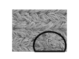
- a photograph of a cross section of sample A1 processed five times.
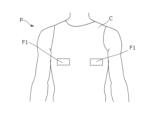
- FIG. 1 is a diagram showing the appearance of clothing C according to this embodiment.
- the clothing C is worn by the wearer P, and contacts the wearer's body to detect the bioelectrical potential of the wearer P.
- Bio information is information obtained from detected biopotentials, and includes, for example, electrocardiogram, heartbeat, respiration, pulse wave, body temperature, myoelectricity, electroencephalogram, eyeball potential, blood pressure, sweat rate, blood sugar level, humidity, etc. .
- the biological information may be any information that can be obtained by the wearer's P's body touching the electrode area.
- biological information is electrocardiogram.
- the "inside" of clothing C etc. is the side near the wearer's P body, and the "outside” is the side far from the wearer's P body.
- the clothing C shown in FIG. 1 is clothing worn by the wearer P on the upper body.
- a detection area F1 is provided on the front of the clothing C between the chest and abdomen of the wearer P.
- FIG. 2 is a diagram showing an example of a cross section of the clothing C in the detection area F1.
- the clothing C has an electrode 1 and an insulating fiber fabric 2 in the detection area F1.
- the electrode 1 is provided inside the detection area F1 in the clothing C so as to be in contact with the body of the wearer P. Therefore, this clothing C is an example of clothing that includes a clothing material to be worn by the wearer and an electrode provided on the surface of the clothing material at a position that contacts the wearer's body when worn.
- the clothing C includes a transmitter that transmits biological signals detected by the electrode 1 to an external device, wiring that connects the transmitter and the electrode 1 in a communicable manner, and insulation that protects the wiring and the electrode 1. It may have members, etc.
- the insulating member is, for example, a urethane sheet that is bonded to the insulating fiber fabric 2 by heating and pressurizing.
- the insulating fiber fabric 2 is a clothing material worn by the wearer P, and is a fabric that constitutes the majority of the clothing C.
- This insulating fiber fabric 2 is a fibrous fabric formed by weaving or knitting fibers that do not easily conduct electricity (referred to as insulating fibers).
- the insulating fiber fabric 2 is, for example, a knitted fabric, a woven fabric, a nonwoven fabric, or the like.
- FIG. 3 is a diagram showing an example of the structure of the insulating fiber fabric 2.
- the insulating fiber fabric 2 shown in FIG. 3 is formed by knitting insulating fibers 21.
- the insulating fibers 21 are highly elastic fibers (elastic fibers) so that they can easily adhere to the body of the wearer P.
- the elastic fibers are preferably fibers with an expansion/contraction ratio of at least 50%.
- This elastic fiber is, for example, polyurethane.
- the elastic fiber used for the insulating fiber 21 is not limited to polyurethane, and may be, for example, elastic polyester, natural rubber fiber, heat-shrinkable nylon, or the like.
- the insulating fiber 21 may be a composite yarn formed of multiple types of insulating fibers.
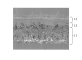
- the electrode 1 shown in FIG. 2 has a conductive fiber fabric layer 11, a conductive elastomer layer 12, and a dipping layer 13.
- the conductive fiber fabric layer 11 is the outermost layer
- the conductive elastomer layer 12 is the innermost layer
- the dipping layer 13 is a layer included in the conductive fiber fabric layer 11 and is a layer sandwiched between the conductive fiber fabric layer 11 and the conductive elastomer layer 12.
- the conductive fiber fabric layer 11 is an example of a conductive fiber fabric layer that is a conductive fiber fabric.
- the conductive fiber fabric layer 11 is a fiber fabric formed by weaving or knitting threads containing conductive fibers (referred to as conductive fibers).
- the conductive fiber fabric layer 11 shown in FIG. 2 is formed integrally with the insulating fiber fabric 2.
- the conductive fiber fabric layer 11 shown in FIG. Note that the conductive fiber fabric layer 11 is not limited to being formed integrally with the insulating fiber fabric 2.
- the conductive fiber fabric layer 11 may be formed as a knitted fabric, a woven fabric, etc. using a thread containing conductive fibers separately from the insulating fiber fabric 2, and may be sewn onto the insulating fiber fabric 2.
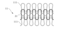
- FIG. 4 is a diagram showing an example of the structure of the conductive fiber fabric layer 11.
- the conductive fiber fabric layer 11 is formed by weaving conductive composite yarn 111 into the above-mentioned insulating fiber 21, as shown in FIG.
- the conductive fiber fabric layer 11 may be integrally formed with the insulating fiber fabric 2 by weaving common insulating fibers 21 so that there is no step difference.
- FIG. 5 is a diagram showing an example of the conductive composite yarn 111.
- This conductive composite yarn 111 is a composite yarn formed by winding conductive fibers 1111 around elastic fibers 1110.
- the elastic fibers 1110 are fibers with relatively high elasticity.
- the elastic fibers 1110 are desirably fibers with an expansion/contraction ratio of at least 50%.
- This elastic fiber 1110 is, for example, polyurethane.
- the elastic fibers 1110 may be, for example, elastic polyester, natural rubber fibers, heat-shrinkable nylon, or the like. Moreover, this elastic fiber 1110 may be used in common with the insulating fiber 21.
- the conductive fibers 1111 are conductive fibers, and are made by adding a conductive substance to non-conductive fibers (referred to as non-conductive fibers).
- the conductive substance is, for example, a metal such as silver, copper, stainless steel, nickel, or aluminum. Further, the conductive substance may be a non-metal such as carbon or a conductive polymer.
- the conductive composite yarn 111 shown in FIG. 5 is an example of a yarn containing conductive fibers, and is an example of a conductive composite yarn formed by winding conductive fibers around elastic fibers.
- the conductive fiber fabric layer 11 is formed by weaving the conductive composite yarn 111 into the insulating fiber 21.
- the conductive fiber fabric layer 11 is formed by weaving the conductive composite yarn 111 into the insulating fiber 21. This is an example of a fabric layer.
- the conductive substance is added to the non-conductive fibers by, for example, wet coating treatment such as electroless metal plating treatment.
- the conductive fiber 1111 shown in FIG. 5 is, for example, a thread made of silver-plated nylon.
- the ratio of silver to nylon may be at least 10 mass percent, but preferably at least 20 mass percent, and preferably at least 30 mass percent. is more desirable.
- the method for adding a conductive substance to non-conductive fibers is not limited to wet film treatment, and may also be, for example, vapor deposition, sputtering, adhesion of metal foil, impregnation, etc.
- the conductive fiber 1111 may be formed, for example, by impregnating acrylic fiber with copper sulfide.
- the non-conductive fiber used for the conductive fiber 1111 is, for example, nylon. Note that this non-conductive fiber may be any fiber whose conductivity is below a predetermined threshold value. Thus, the non-conductive fibers may be, for example, cellulose, natural fibers such as raw silk, or other synthetic fibers. By using natural fibers as the non-conductive fibers, the clothing C can be worn even if the wearer P is allergic to synthetic fibers.
- the conductive fibers 1111 do not need to contain non-conductive fibers as long as they have conductivity. Further, the conductive fiber fabric layer 11 does not need to be woven into the insulating fibers 21 as long as it has conductivity as a whole.
- the conductive fiber fabric layer 11 may be formed by knitting only the conductive composite yarns 111.
- the conductive composite yarn 111 shown in FIG. 5 is formed by wrapping the conductive fibers 1111 twice around an elastic fiber 1110 as a core yarn. That is, the conductive composite yarn 111 is formed from a double covered yarn.
- this conductive composite yarn 111 is made by first winding a lower yarn 1111a, which is a conductive fiber 1111, around an elastic fiber 1110, and then winding an upper yarn 1111b, which is a conductive fiber 1111, in the opposite direction thereon. It is formed by attaching it.
- the conductive elastomer layer 12 is formed by applying a paste to the inner surface of the conductive fiber fabric layer 11 and drying the paste.
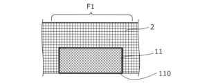
- FIG. 6 is a diagram showing the state of the conductive fiber fabric layer 11 before applying the paste.
- the conductive fiber fabric layer 11 is formed on at least one surface of the insulating fiber fabric 2 so that there is no step, for example.
- the surface 110 is the side of the conductive fiber fabric layer 11 that is closer to the wearer P (not shown in FIG. 6), that is, the inner surface.
- FIG. 7 is a diagram showing the state of the conductive fiber fabric layer 11 when the paste is applied. As shown in FIG. 7, a paste containing an elastomer composition 120 and a conductive filler 121 is applied to the inner surface 110 of the conductive fiber fabric layer 11.
- the elastomer composition 120 shown in FIG. 7 is obtained by dissolving an elastomer in a solvent.
- this elastomer include silicone rubber, fluororubber, nitrile rubber, acrylic rubber, styrene rubber, chloroprene rubber, ethylene propylene rubber, and urethane rubber.
- the solvent for dissolving the above-mentioned elastomer for example, aliphatic hydrocarbons, aromatic hydrocarbons, ethers, haloalkanes, carboxylic acid amides, sulfoxides, etc. are used.
- aliphatic hydrocarbons examples include pentane, hexane, cyclohexane, heptane, methylcyclohexane, ethylcyclohexane, octane, decane, and tetradecane.
- Aromatic hydrocarbons include benzene, toluene, ethylbenzene, xylene, trifluoromethylbenzene, benzotrifluoride, and the like.
- the ethers include diethyl ether, diisopropyl ether, dibutyl ether, cyclopentyl methyl ether, cyclopentyl ethyl ether, ethylene glycol dimethyl ether, ethylene glycol diethyl ether, diethylene glycol dimethyl ether, 1,4-dioxane, 1,3-dioxane, tetrahydrofuran, and the like.
- haloalkanes include dichloromethane, chloroform, 1,1-dichloroethane, 1,2-dichloroethane, 1,1,1-trichloroethane, and 1,1,2-trichloroethane.
- Carboxylic acid amides include N,N-dimethylformamide, N,N-dimethylacetamide, and the like.
- Sulfoxides include dimethyl sulfoxide, diethyl sulfoxide, and the like. Note that the solvent may be one type of these, or a mixture of two or more of these at any ratio.
- the content of the elastomer in the paste is preferably 3% by mass or more, more preferably 5% by mass or more, and even more preferably 7% by mass or more, based on the entire solid content of the paste. Further, the content of the elastomer in the paste is preferably 30% by mass or less, more preferably 25% by mass or less, and even more preferably 20% by mass or less, based on the entire solid content of the paste. preferable.
- the conductive filler 121 shown in FIG. 7 is a fine solid that has conductivity.
- This conductive filler 121 is not particularly limited, but includes, for example, copper, silver, gold, nickel, tin, lead, zinc, bismuth, antimony, metal powder made of an alloy of these, a conductive organic compound, and a conductive carbon material. It contains at least one kind, or two or more kinds of these.
- the conductive filler preferably contains silver or copper from the viewpoint of high conductivity or high availability. That is, it is preferable that the conductive filler contains silver powder or copper powder.
- the conductive filler may be coated with other metals.
- the shape of the conductive filler there are no restrictions on the shape of the conductive filler, but conventionally used shapes such as dendritic, spherical, and flaky shapes can be used.
- the paste described above is manufactured by adding a conductive filler 121 to an elastomer composition 120.
- the added conductive fillers 121 come into contact with each other in the elastomer composition 120 and impart conductivity to the entire paste.
- the content of the conductive filler in the paste is preferably 60% by mass or more, more preferably 65% by mass or more, and still more preferably 70% by mass or more, based on the entire solid content of the paste. preferable. Further, the content of the conductive filler in the paste is preferably 90% by mass or less, more preferably 88% by mass or less, and 85% by mass or less based on the entire solid content of the paste. is even more preferable.
- the paste described above may contain silica particles, if necessary. By including these silica particles, it is possible to improve the hardness and mechanical strength of a cured product formed from the paste.
- the silica particles preferably have a specific surface area of 10 to 400 m2/g, more preferably 20 to 400 m2/g.
- the median diameter D50 is preferably 1 to 100 nm, more preferably 5 to 20 nm.
- the particle size of the silica particles can be defined as the average value of 200 arbitrarily selected silica particles, for example, by observing the paste or its cured product with a transmission electron microscope or the like and performing image analysis.
- the silica particles are not particularly limited, for example, fumed silica, calcined silica, precipitated silica, etc. can be used.
- only one type of silica particles may be used alone, or two or more types may be used in combination.
- the content of silica particles in the paste described above is preferably 1% by mass or more, more preferably 2% by mass or more, and preferably 3% by mass or more, based on the entire solid content of the paste. More preferred. Further, the content of silica particles in the paste is preferably 15% by mass or less, more preferably 12% by mass or less, and preferably 10% by mass or less based on the entire solid content of the paste. More preferred.
- the cured product of the paste can have appropriate mechanical strength. Furthermore, by controlling the content of silica particles to be equal to or less than the above upper limit, the cured product can have appropriate conductive properties.
- FIG. 8 is a diagram showing the state of the electrode 1 after the paste has been dried.
- the paste becomes the conductive elastomer layer 12 shown in FIG. 8, for example, by volatilizing a certain amount of the solvent.
- a conductive elastomer layer 12 is formed inside the surface 110 of the conductive fiber fabric layer 11. That is, this conductive elastomer layer 12 is an example of a conductive elastomer layer containing an elastomer composition and a conductive filler, which is formed on at least one surface of the conductive fiber fabric layer.
- the surface 110 of the conductive fiber fabric layer 11 is immersed in the applied paste. Then, by drying the soaked paste, a soaked layer 13 is formed on the surface 110 side of the conductive fiber fabric layer 11.
- the dipping layer 13 contains an elastomer composition 120 and a conductive filler 121 in the gaps between the fibers of the conductive fiber fabric layer 11 . Therefore, the conductive fiber fabric layer 11 including this dipped layer 13 on the surface 110 side is a conductive fibrous fabric layer having a dipped layer impregnated with the elastomer composition and the conductive filler on at least one surface. This is an example.
- the electrode 1 has a conductive elastomer layer 12 on the innermost side. Since the conductive elastomer layer 12 is formed by containing the elastomer composition 120, its surface is smoother than, for example, conductive fibers. Therefore, compared to other electrodes that do not have the conductive elastomer layer 12, the electrode 1 can easily adhere to the body of the wearer P without gaps and is less susceptible to noise.
- the dipping layer 13 has a structure in which a conductive filler 121 that is electrically connected to the conductive elastomer layer 12 is intricately inserted into the gap between the conductive composite yarns 111 forming the conductive fiber fabric layer 11 . Therefore, the dipping layer 13 strengthens the electrical conduction between the conductive fiber fabric layer 11 and the conductive elastomer layer 12.
- this electrode 1 is made by (1) forming a conductive fiber fabric layer 11 on at least one surface of the insulating fiber fabric 2, and (2) applying a paste to the inner surface 110 of the conductive fiber fabric layer 11. , and (3) drying the paste to form the conductive elastomer layer 12 (and immersion layer 13), but the steps for creating the electrode 1 are not limited to this.
- the electrode 1 may be created in the order of (2) ⁇ (1) ⁇ (3), or may be created in the order of (2) ⁇ (3) ⁇ (1).
- the step (1) is not limited to forming the conductive fiber fabric layer 11 integrally with the insulating fiber fabric 2 as described above. Therefore, for example, the electrode 1 can be made by (2) applying a paste to the inner surface 110 of the conductive fiber fabric layer 11 and then (1) applying the paste to the inner surface 110 of the conductive fiber fabric layer 11. (3) drying the paste to form the conductive elastomer layer 12.
- the myoelectric potential becomes noise.
- the electrode 1 is provided in the detection area F1 between the chest and abdomen of the wearer P in the clothing C and in contact with areas that are not easily affected by the myoelectric potential, such as the pectoralis major muscle and the rectus abdominis muscle.
- FIG. 9 is a diagram showing an example of the position of the detection area F1.
- the detection region F1 is preferably a region that is not easily influenced by myoelectric potentials such as the pectoralis major muscle and the rectus abdominis muscle, as described above.
- the detection area F1 shown in FIG. 9 is an area that contacts the skin covering the fifth rib r5 to the sixth rib r6 on the front surface of the torso of the wearer P.
- the detection region F1 may be a region of the wearer's P's torso that contacts the skin at the same height as the xiphoid process E. That is, the electrode 1 provided in the detection area F1 is an example of an electrode that contacts a part of the wearer's torso at the same height as the xiphoid process.
- FIG. 10 is a diagram showing an example of the position of the detection area F2.
- the detection area F2 is an area where electrodes were provided in the conventional technology.
- the detection region F2 shown in FIG. 10 is located at a position lower than the xiphoid process E in the torso of the wearer P.
- the detection area F2 shown in FIG. 10 is an area that contacts the skin covering from the seventh rib r7 to the eighth rib r8.
- the conductive fiber fabric layer 11 of the electrode 1 uses the conductive composite yarn 111 as the yarn containing conductive fibers, but the yarn is not limited to the composite yarn.
- the conductive fibers 1111 may be used as they are.
- the conductive fiber fabric layer 11 may be, for example, a fiber fabric formed by knitting conductive fibers, which are silver-plated nylon threads, into polyurethane elastic fibers.
- the conductive fiber fabric layer 11 is formed by weaving yarns containing conductive fibers, but it may be any fabric as long as it has conductivity.
- the conductive fiber fabric layer 11 is a fiber fabric in which a conductive substance is formed on the surface of an insulating fiber fabric that has no conductivity, or the surface of a non-conductive fiber fabric whose conductivity does not meet a certain level. It's okay.
- This conductive material is formed by, for example, depositing a film by plating.
- the conductive fiber fabric layer 11 may be a fiber fabric made of an insulating fabric woven with nylon and polyurethane and plated with silver.
- the conductive fiber fabric layer 11 in this modification has a conductive film layer, which is formed by depositing a conductive film on an insulating fiber fabric made of insulating fibers that insulate electricity, on at least one surface. This is an example of a fibrous fabric layer.
- the conductive elastomer layer 12 was formed by applying and drying one type of paste, but may be formed by sequentially applying two or more types of paste.
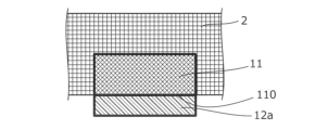
- FIG. 11 is a diagram showing an example of the initial stage of formation of the conductive elastomer layer 12 in a modified example. As shown in FIG. 11, a first paste is applied to the surface 110 of the conductive fiber fabric layer 11. This first paste, after drying, forms the first conductive elastomer layer 12a.
- FIG. 12 is a diagram showing an example in which the conductive elastomer layer 12 is being formed in a modified example. As shown in FIG. 12, a second paste is applied to the surface of the first conductive elastomer layer 12a. This second paste forms the second conductive elastomer layer 12b after drying.
- FIG. 13 is a diagram showing an example of the final stage of the conductive elastomer layer 12 in a modified example.
- the electrode 1 shown in FIG. 13 includes a conductive fiber fabric layer 11 with a dipping layer 13 formed therein, a first conductive elastomer layer 12a, and a second conductive elastomer layer 12b.
- a first conductive elastomer layer 12a is formed inside the dipping layer 13.
- the second conductive elastomer layer 12b is formed inside the first conductive elastomer layer 12a.
- the concentration of the conductive filler 121 may be a difference in the concentration of the conductive filler 121 (see FIG. 7) between the first paste and the second paste.
- the second paste in this modification has a higher concentration of conductive filler 121 than the first paste. That is, the first paste in this modification has a lower concentration of conductive filler than the second paste.
- the first conductive elastomer layer 12a is closer to the conductive fiber fabric layer 11 than the second conductive elastomer layer 12b, and has a thinner concentration of conductive filler 121.
- this conductive elastomer layer 12 in the modified example is an example of a conductive elastomer layer having a region where the concentration of the conductive filler becomes thinner as it approaches the conductive fiber fabric layer.
- This conductive elastomer layer 12 has a higher concentration of conductive filler 121 on the side farther away from the conductive fiber fabric layer 11 and closer to the body of the wearer P. Therefore, this conductive elastomer layer 12 contains a large amount of conductive filler 121 in the parts that are more easily exposed to impact, friction, etc. and easily peeled off, so it is more resistant to impact, friction, etc. than a layer with a uniform concentration. Expected to show gender.
- the electrode 1 was provided on the clothing C, but it may also be provided on the belt.
- FIG. 14 is a diagram showing an example of belt B in a modification.
- the belt B includes a stretchable belt member 2a and an electrode 1 provided on the surface of the belt member 2a.
- the electrode 1 is provided at a position where it comes into contact with the body of the wearer P when the belt B is wrapped around the wearer P.
- this belt B includes a belt member having elasticity, an electrode provided on the surface of the belt member at a position that contacts the wearer's body when the belt member is wrapped around the wearer, This is an example of a belt having
- FIG. 15 is a diagram showing an example of a state in which the belt B is worn in a modified example.
- Belt B is wound between the chest and abdomen of wearer P so that electrode 1 is placed in detection area F1.
- the detection area F1 shown in FIG. 15 is located at the same position as the detection area F1 shown in FIG. That is, the electrode 1 provided on the belt B is an example of an electrode that contacts a portion of the wearer's torso at the same height as the xiphoid process.
- the electrodes 1 of the belt B can come into contact with the body of the wearer P in the detection region F1 and detect biological signals.
- the electrode 1 since the electrode 1 has the conductive fiber fabric layer 11 and the conductive elastomer layer 12, it can easily adhere to the body of the wearer P and is not easily affected by noise.
- Example> ⁇ Experiment example> ⁇ Experiment A (simulated laundry experiment)> ⁇ Sample> The inventors of the present invention conducted an experiment (hereinafter referred to as Experiment A) in which a sample was subjected to a treatment simulating washing, and the appearance of the sample before and after the treatment was photographed and evaluated.
- the samples used in Experiment A were one consisting only of AGPoss (registered trademark, the same hereinafter) manufactured by Mitsufuji Co., Ltd.
- sample A1 (hereinafter referred to as sample A1), and one consisting only of AGPoss (registered trademark, the same hereinafter) manufactured by Mitsufuji Co., Ltd., and one consisting only of AGPoss (hereinafter referred to as sample A1) manufactured by Mitsufuji Co., Ltd.;
- sample A2 A sample (hereinafter referred to as sample A2) printed (coated and dried) with a registered trademark (the same applies hereinafter) was used.
- AGPoss is an example of the conductive fiber fabric layer 11.
- DuraQ is an example of the conductive elastomer layer 12.
- AGPoss used was a nylon polyurethane elastic fiber to which 10% by mass or more of silver was added by plating.
- DuraQ used a paste-like product in which silicone rubber was dissolved in a hydrocarbon solvent such as decane or tetradecane, and silver powder was added and mixed so that the solid content concentration was about 70% by mass. there was.
- Sample A2 was formed by applying a conductive paste in a direction substantially perpendicular to the grain of the AGPoss fibers and drying it. Sample A2 has DuraQ formed on 1.3 cm square of the surface of AGPoss. The concentration of the conductive filler in the conductive paste was 86% by mass, and the amount of paste adhered was 39.5 mg/cm 2 (milligrams per square centimeter).
- FIG. 16 is a flowchart showing the flow of an experiment on the influence of a load on an electrode by simulating washing.
- the experimenter performed the following steps S101 to S105 to apply a load simulating washing to the sample.
- the experimenter determines whether or not the sample has been processed a predetermined number of times (step S101), and if it is determined that the process has been processed the predetermined number of times (step S101; YES), the sample is placed under a scanning electron microscope (SEM). :Scanning Electron Microscope) and evaluated it (Step S102).
- SEM scanning electron microscope
- step S101 the experimenter repeated the processes from step S103 to step S105 while determining that the process had not been performed the prescribed number of times (step S101; NO).
- the experimenter first stretched and contracted the sample in both the vertical and horizontal directions 300 times at a stretching ratio of 50% (step S103).
- the stretch ratio is the percentage of the length increased by stretching with respect to the length of the sample under no load. In other words, in this stretching experiment, the sample is stretched up to 1.5 times its length.
- the experimenter immersed the sample in the linen liquid and stirred it for 20 hours (step S104).
- the linen liquid was prepared by adding 1.5 ml of hydrogen peroxide and 1.5 ml of a 30 w/v% aqueous sodium hydroxide solution to 1 liter of water.
- the temperature of the linen liquid is maintained at 85°C. Note that in the present invention, w/v% indicates the ratio of mass (grams) to a total volume of 100 milliliters.
- step S105 the experimenter dried the sample at 110° C. for 20 minutes.
- FIG. 17 is a photograph of the surface of untreated sample A1.
- FIG. 18 is a photograph of a cross section of untreated sample A1. Since these are unprocessed, the specified number of times mentioned above is 0. As shown in FIGS. 17 and 18, no damage to the silver plating formed on the surface of the fibers was observed in sample A1 in the untreated state.
- FIG. 19 is a photograph of the surface of sample A1 that has been treated five times.
- FIG. 20 is a photograph of a cross section of sample A1 that has been treated five times. The prescribed number of times is five. As shown in FIGS. 19 and 20, damage to the silver plating was observed in sample A1 by repeating the process from step S103 to step S105 described above five times.
- FIG. 21 is a photograph of the surface of untreated sample A2.
- FIG. 22 is a photograph of a cross section of untreated sample A2. Since these are unprocessed, the specified number of times mentioned above is 0. As shown in FIGS. 21 and 22, no damage was observed in the silver plating on the fiber surface of sample A2 in the untreated state. Further, since the surface of sample A2 was covered with DuraQ, which is an example of the conductive elastomer layer 12, the shape of the AGPoss fibers, which is an example of the conductive fiber fabric layer 11, was not visually recognized. As shown in FIG.
- This soaked layer 13 is a layer in which DuraQ is soaked in AGPoss fibers.
- FIG. 23 is a photograph of the surface of sample A2 that has been treated five times.
- FIG. 24 is a photograph of a cross section of sample A2 that has been treated five times. The prescribed number of times is five. As shown in FIGS. 23 and 24, no damage to the silver plating was observed in sample A2 even after the above-described treatment was repeated five times. Even after these five treatments, the above-mentioned immersion layer 13 had not disappeared.
- Experiment B electrode durability experiment
- Experiments have shown that the electrode 1 described above has improved durability against washing because it has the conductive elastomer layer 12.
- the inventors of the present application conducted an experiment (hereinafter referred to as Experiment B) in which a sample was subjected to a treatment simulating washing and the resistance to the treatment was evaluated. This resistance was evaluated by measuring the sheet resistance of the sample at each treatment time.
- Table 1 is a table in which changes in sheet resistance of the electrode 1 according to the present invention are recorded for each washing time.
- sample B2 shows the sheet resistance when electrode 1 was washed with a commercially available chlorine bleach.
- the electrode 1 in sample B2 is obtained by printing (coating and drying) the above-mentioned DuraQ on the surface of the above-mentioned AGPoss.
- sample B1 shows the sheet resistance when an electrode having the same structure as the conductive fiber fabric layer 11 described above was washed with a commercially available chlorine bleach.
- the electrode in sample B1 is composed only of the above-mentioned AGPoss.
- N/D indicates non-detection.
- sample B2 that is, electrode 1 according to the present invention
- sample B1 that is, the electrode without the conductive elastomer layer 12
- the sheet resistance was no longer detected after 60 minutes.
- the conductive elastomer layer 12 protects the conductive fiber fabric layer 11 and prevents the conductive material from peeling off due to friction, impact, etc. during washing.
- the conductive fiber fabric layer 11 is disposed below (that is, on the outside) of the conductive elastomer layer 12. Therefore, even if the conductive elastomer layer 12 breaks, the conductive fiber fabric layer 11 electrically connected to each broken conductive elastomer layer 12 is protected by the conductive elastomer layer 12. The conductivity of electrode 1 is maintained.
- the sheet resistance of the conventional electrode was 1.34 ⁇ 10 ⁇ 1 ⁇ / ⁇ .
- the sheet resistance of the electrode 1 is 3.40 ⁇ 10 ⁇ 2 ⁇ / ⁇ .
- the sheet resistance of the conventional electrode was about 1 ⁇ 10 -1 ⁇ / ⁇
- the sheet resistance of the electrode 1 according to the present invention was about 1 ⁇ 10 -3 ⁇ / ⁇ . It has improved to about ⁇ / ⁇ . That is, the electrode 1 has a lower sheet resistance than conventional electrodes. This is thought to be due to the effect of the immersion layer 13 in addition to the effect of the conductive elastomer layer 12.
- Experiment C (actual machine linen washing experiment)> The inventors of the present application conducted an experiment (hereinafter referred to as Experiment C) in which the samples were actually washed, the surface resistance values of the samples were measured each time the samples were washed, and the surface resistance values were evaluated.
- the washing in Experiment C was carried out at a preliminary washing temperature of 40°C and an actual washing temperature of 80°C for 10 minutes.
- a commercial washing machine SWX-60WU manufactured by Tokyo Rinsenki Kikai Seisakusho was used.
- As detergent 300 ml of 30 w/v % sodium hydroxide was used for each wash. It was expected that the pH would be 10 by using this detergent.
- 300 ml of 35 w/v % hydrogen peroxide was used for each wash. Drying performed after each wash was performed by heating the sample at 80° C. for 13 minutes.
- Table 2 is a table in which the surface resistance values of the electrodes are recorded for each number of times the clothing C according to the present invention was washed.
- sample C2 shows the surface resistance value of electrode 1 when clothing C was washed in an actual linen machine.
- the electrode 1 in sample C2 is obtained by coating and drying the above-mentioned DuraQ on the surface of the above-mentioned AGPoss, and its thickness is equivalent to six masks.
- DuraQ used here expresses the thickness in units called masks. This mask has layers each having a thickness of 125 ⁇ m (micrometers). Therefore, since this sample C2 is equivalent to six masks, it has a DuraQ layer (conductive elastomer layer 12) with a thickness of 750 ⁇ m (micrometers). Further, in this sample C2, a conductive paste having a conductive filler concentration of 71% by mass was used as a conductive paste which is a precursor of DuraQ.
- sample C1 shows the surface resistance value of the electrode when clothing provided with an electrode having the same configuration as the conductive fiber fabric layer 11 described above was washed using an actual linen machine.
- the electrode in sample C1 is composed only of the above-mentioned AGPoss.
- O/L indicates that the upper limit of measurement was exceeded.
- FIG. 25 is a graph showing Table 2 mentioned above.
- the reference line Q is a line indicating a surface resistance value of 1.0 ⁇ (ohm), and indicates the quality standard of the electrode. If the surface resistance value is lower than this reference line Q, the electrode satisfies the quality standards. On the other hand, if a surface resistance value of 1.0 ⁇ (ohm) or more indicated by this reference line Q is measured, the electrode does not meet the quality standards.
- the graph shown by the broken line in FIG. 25 represents the measurement results of sample C1 in Table 2.
- sample C1 no longer satisfies the quality standards after being washed 10 times, and after being washed more than 30 times, the surface resistance value exceeds the upper limit of measurement.
- sample C1 made of only AGPoss which is an example of the conductive fiber fabric layer 11, no longer satisfies the quality standards after just 10 washes.
- the graph shown by the solid line in FIG. 25 represents the measurement results of sample C2 in Table 2.
- sample C2 met the quality standards even after being washed 60 times, and stopped meeting the quality standards only after being washed more than 70 times.
- sample C2 which is an example of electrode 1 of the present invention, satisfies the quality standards even after washing 60 times.
- experiment D Noise resistance experiment
- the inventors of the present application conducted an experiment (hereinafter referred to as experiment D) to verify noise resistance using the electrode 1 of the invention according to the present application.
- the samples used in this experiment D are sample D1, which is an example of the prior art, and sample D2, which includes electrode 1, which is an example of the invention according to the present application.
- Sample D1 is a belt provided with electrodes consisting only of the conventional conductive fiber fabric layer 11.
- Sample D2 is a belt provided with an electrode 1 according to the invention of the present application, in which a conductive elastomer layer 12 is formed by applying a paste to a conductive fiber fabric layer 11 and drying it.
- the conductive fiber fabric layer 11 is the above-mentioned AGPoss.
- the conductive elastomer layer 12 is the above-mentioned DuraQ.
- the subject wears sample D1 and sample D2 so that the electrodes are located in detection area F2 shown in FIG. 9, performs four specified movements, and has electrocardiographic waveforms measured in each state. .
- “Walking” in Table 3 is a state of walking in time with a tempo of 80 recorded by a metronome.
- tempo 80 is the number of beats per minute, and is also called 80 bpm (beats per minute). In other words, a subject walking this way takes 80 steps per minute.
- Observation is performed by extracting R waves from the electrocardiogram waveform in each state of the subject wearing each sample, determining whether the R waves are normal values, and calculating the ratio of normal values of the R waves. went.
- the numerical values shown in Table 3 are percentages (referred to as normal rate of R waves) with all acquired R waves as the denominator and R waves determined as normal values as the numerator.
- the electrode 1 according to the present invention exhibits the same level of noise resistance as the conventional electrode consisting only of the conductive fiber fabric layer 11.
- Example E detection area comparison experiment
- the inventors of the present application conducted an experiment (hereinafter referred to as "Experiment E") to compare the influence of the detection area that the electrode 1 of the invention according to the present invention contacts on noise resistance.
- This experiment E was conducted by attaching the electrodes included in the sample D2 used in the above-described experiment D so as to be located in the detection area F1 shown in FIG. 9 and the detection area F2 shown in FIG. 10, respectively.
- Table 4 is a table showing the observation results in Experiment E.
- experiment E1 is data obtained by arranging the electrode of sample D2 described above in the detection area F1 (see FIG. 9) of the subject and observing the subject based on the normality rate of the R wave for each condition of the subject.
- experiment E2 the electrode of sample D2, which is common to experiment E1, was placed in the detection area F2 of the subject (see Figure 10), and the subject was observed based on the normality rate of R waves for each condition of the subject. It is data.
- Experiment E1 showed better noise resistance than Experiment E2 in all conditions of the subjects. That is, it has become clear that noise is significantly reduced when the electrodes are placed in the detection area F1 shown in FIG. 9, compared to when they are placed in the detection area F2 shown in FIG.
- Electrode 11... Conductive fiber fabric layer, 110... Surface, 111... Conductive composite yarn, 1110... Elastic fiber, 1111... Conductive fiber, 1111a... Lower winding thread, 1111b... Upper winding thread, 12... Conductive elastomer layer , 120... Elastomer composition, 121... Conductive filler, 12a... First conductive elastomer layer, 12b... Second conductive elastomer layer, 13... Dipping layer, 2... Insulating fiber fabric, 21... Insulating fiber, 2a ... Belt member, E... Xiphoid process, F1... Detection area, F2... Detection area, r5... 5th rib, r6... 6th rib, r7... 7th rib, r8... 8th rib.
Landscapes
- Health & Medical Sciences (AREA)
- Life Sciences & Earth Sciences (AREA)
- Engineering & Computer Science (AREA)
- Textile Engineering (AREA)
- General Health & Medical Sciences (AREA)
- Heart & Thoracic Surgery (AREA)
- Molecular Biology (AREA)
- Biophysics (AREA)
- Pathology (AREA)
- Biomedical Technology (AREA)
- Veterinary Medicine (AREA)
- Medical Informatics (AREA)
- Physics & Mathematics (AREA)
- Surgery (AREA)
- Animal Behavior & Ethology (AREA)
- Public Health (AREA)
- Physical Education & Sports Medicine (AREA)
- Chemical & Material Sciences (AREA)
- Chemical Kinetics & Catalysis (AREA)
- Measurement And Recording Of Electrical Phenomena And Electrical Characteristics Of The Living Body (AREA)
- Professional, Industrial, Or Sporting Protective Garments (AREA)
Abstract
[Problem] To provide a belt or clothing that uses electrodes that have higher noise resistance and durability than electrodes made only of a conductive fiber fabric or a conductive elastomer fabric. [Solution] Clothing C includes: an electrode 1 in a detection area F1; and an insulating fiber fabric 2. The electrode 1 is provided on the inner side of the detection area F1 on the clothing C so as to come into contact with the body of a wearer P. The insulating fiber fabric 2 is a clothing material to be worn by the wearer P, and is a fabric that constitutes most of the clothing C. The electrode 1 has: a conductive fiber fabric layer 11; and a conductive elastomer layer 12. The conductive fiber fabric layer 11 is a fiber fabric formed by weaving or knitting yarns containing conductive fibers having conductive properties. The conductive elastomer layer 12 is formed by applying a paste containing an elastomer composition 120 and a conductive filler 121 to the inner side of the conductive fabric layer 11 and drying the paste.
Description
本発明は、生体電位を検出可能な電極を有するベルト、及び被服に関する。
The present invention relates to a belt and clothing having electrodes capable of detecting biopotential.
着用者の生体電位を検出するために導電性繊維を用いた繊維生地が開発されている。特許文献1には、選択的に露出される導電性繊維と、繊維構造に弾力性を与える非導電性繊維と、が個別に織られた組合せで形成される繊維生地インタフェースが記載されている。
Fiber fabrics using conductive fibers have been developed to detect the wearer's biopotential. Patent Document 1 describes a fibrous fabric interface formed by an individually woven combination of conductive fibers that are selectively exposed and non-conductive fibers that impart elasticity to the fibrous structure.
特許文献1に示す通り、例えば、導電性を有する繊維(導電性繊維)を含む糸を織って形成された繊維生地インタフェースは、表面に繊維特有の凹凸があり、身体との密着性が低い。そのため、従来の繊維生地インタフェース等の電極は、体動によって電極がノイズを拾ってしまうことがあった。また、従来の電極のシート抵抗は、10-1Ω/□程度であった。
As shown in Patent Document 1, for example, a fiber fabric interface formed by weaving threads containing conductive fibers (conductive fibers) has unevenness unique to the fibers on the surface and has low adhesion to the body. Therefore, in conventional electrodes such as textile fabric interfaces, the electrodes sometimes pick up noise due to body movements. Further, the sheet resistance of conventional electrodes was about 10 -1 Ω/□.
また、この繊維生地インタフェースは、衣服に編み込まれて利用されることがあるが、この衣服を複数回にわたって洗濯すると、その一部が剥離、脱落して導電性を失い、機能しなくなることがあった。特に、洗濯に用いられる洗剤、リネン液には、酸性のもの、アルカリ性のもの等、各種の薬品が含まれるため、繊維生地インタフェースは、洗濯の際にそれら薬品と反応し、導電性を失うことがある。これらの体動における耐ノイズ性、洗濯等に対する耐久性は、糸を織ったもの、編んだものに限らず、例えば不織布等も含めて繊維生地インタフェース全般に関する課題である。
In addition, this textile fabric interface is sometimes used by being woven into clothing, but if this clothing is washed multiple times, some of it may peel off or fall off, lose its conductivity, and become inoperable. Ta. In particular, detergents and linen liquids used for laundry contain various chemicals such as acidic and alkaline chemicals, so textile fabric interfaces can react with these chemicals and lose their conductivity during washing. There is. Noise resistance during these body movements, durability against washing, etc. are issues related to all fiber fabric interfaces, including not only those made of woven or knitted yarns, but also non-woven fabrics.
ところで、生体電位等を測定するための電極は、繊維生地インタフェースのほか、導電性エラストマー生地も含まれる。しかし、導電性エラストマー生地だけで構成された電極にも、繊維生地インタフェースと同様に耐ノイズ性、耐久性に課題があった。
By the way, electrodes for measuring biopotential and the like include not only fiber fabric interfaces but also conductive elastomer fabrics. However, electrodes made only of conductive elastomer fabric also have the same problems with noise resistance and durability as with fiber fabric interfaces.
本発明は、導電性繊維生地、又は導電性エラストマー生地のみで形成された電極に比べて耐ノイズ性、耐久性の高い電極を用いたベルト、又は被服を提供することを目的とする。
An object of the present invention is to provide a belt or clothing using an electrode that has higher noise resistance and durability than electrodes formed only from conductive fiber fabric or conductive elastomer fabric.
本発明の請求項1に係る被服は、着用者に着用される被服素材と、前記被服素材の表面のうち、着用時に前記着用者の身体に接触する位置に設けられている電極と、を有し、前記電極は、導電性を有する繊維生地である導電性繊維生地層と、前記導電性繊維生地層の少なくとも一方の面に形成された、エラストマー組成物及び導電性フィラーを含む導電性エラストマー層と、を有することを特徴とする被服である。
The clothing according to claim 1 of the present invention includes a clothing material to be worn by a wearer, and an electrode provided on the surface of the clothing material at a position that contacts the wearer's body when worn. The electrode includes a conductive fiber fabric layer that is a conductive fiber fabric, and a conductive elastomer layer containing an elastomer composition and a conductive filler formed on at least one surface of the conductive fiber fabric layer. It is a clothing characterized by having the following.
本発明の請求項2に係る被服は、請求項1に記載の態様において、前記電極は、前記着用者の胴体のうち、剣状突起と同じ高さの部位に接触することを特徴とする被服である。
The clothing according to claim 2 of the present invention is the clothing according to claim 1, wherein the electrode contacts a part of the wearer's torso at the same height as the xiphoid process. It is.
本発明の請求項3に係るベルトは、伸縮性を有するベルト部材と、前記ベルト部材の表面のうち、該ベルト部材を着用者に巻きつけたときに該着用者の身体に接触する位置に設けられている電極と、を有し、前記電極は、導電性を有する繊維生地である導電性繊維生地層と、前記導電性繊維生地層の少なくとも一方の面に形成された、エラストマー組成物及び導電性フィラーを含む導電性エラストマー層と、を有することを特徴とするベルトである。
The belt according to claim 3 of the present invention includes a belt member having elasticity and a surface of the belt member that is provided at a position that comes into contact with the wearer's body when the belt member is wrapped around the wearer. The electrode comprises a conductive fiber fabric layer which is a conductive fiber fabric, and an elastomer composition and a conductive material formed on at least one surface of the conductive fiber fabric layer. The belt is characterized by having a conductive elastomer layer containing a conductive filler.
本発明の請求項4に係るベルトは、請求項3に記載の態様において、前記電極は、前記着用者の胴体のうち、剣状突起と同じ高さの部位に接触することを特徴とするベルトである。
The belt according to claim 4 of the present invention is the belt according to claim 3, wherein the electrode contacts a part of the wearer's torso at the same height as the xiphoid process. It is.
本願に係る発明によれば、導電性繊維生地、又は導電性エラストマー生地のみで形成されたものに比べて耐ノイズ性、耐久性が向上する。
According to the invention according to the present application, noise resistance and durability are improved compared to those formed only from conductive fiber fabric or conductive elastomer fabric.
<実施形態>
<被服の外観>
図1は、本実施形態に係る被服Cの外観を示す図である。被服Cは、着用者Pに着用され、その身体に接触してその生体電位を検出する。 <Embodiment>
<Appearance of clothing>
FIG. 1 is a diagram showing the appearance of clothing C according to this embodiment. The clothing C is worn by the wearer P, and contacts the wearer's body to detect the bioelectrical potential of the wearer P.
生体情報は、検出した生体電位から得られる情報であり、例えば、心電、心拍、呼吸、脈波、体温、筋電、脳波、眼球電位、血圧、発汗量、血糖値、湿度等が挙げられる。生体情報は、着用者Pの身体が電極領域に触れることで得られる情報であれば何でもよい。以下の説明で生体情報は心電である。また、以下の説明で被服C等の「内側」とは、着用者Pの身体に近い側であり、「外側」とは、着用者Pの身体から遠い側である。
Biological information is information obtained from detected biopotentials, and includes, for example, electrocardiogram, heartbeat, respiration, pulse wave, body temperature, myoelectricity, electroencephalogram, eyeball potential, blood pressure, sweat rate, blood sugar level, humidity, etc. . The biological information may be any information that can be obtained by the wearer's P's body touching the electrode area. In the following explanation, biological information is electrocardiogram. Moreover, in the following explanation, the "inside" of clothing C etc. is the side near the wearer's P body, and the "outside" is the side far from the wearer's P body.
図1に示す被服Cは、着用者Pが上半身に着用する衣服である。被服Cの前面で、着用者Pの胸部と腹部との間には、検出領域F1が設けられている。
The clothing C shown in FIG. 1 is clothing worn by the wearer P on the upper body. A detection area F1 is provided on the front of the clothing C between the chest and abdomen of the wearer P.
<電極の構成>
図2は、被服Cの検出領域F1における断面の例を示す図である。図2に示す通り、被服Cは、検出領域F1において電極1と、絶縁性繊維生地2とを有する。電極1は、着用者Pの身体に接触するように被服Cにおいて検出領域F1の内側に設けられている。したがって、この被服Cは、着用者に着用される被服素材と、被服素材の表面のうち、着用時に着用者の身体に接触する位置に設けられている電極と、を有する被服の例である。 <Configuration of electrode>
FIG. 2 is a diagram showing an example of a cross section of the clothing C in the detection area F1. As shown in FIG. 2, the clothing C has anelectrode 1 and an insulating fiber fabric 2 in the detection area F1. The electrode 1 is provided inside the detection area F1 in the clothing C so as to be in contact with the body of the wearer P. Therefore, this clothing C is an example of clothing that includes a clothing material to be worn by the wearer and an electrode provided on the surface of the clothing material at a position that contacts the wearer's body when worn.
図2は、被服Cの検出領域F1における断面の例を示す図である。図2に示す通り、被服Cは、検出領域F1において電極1と、絶縁性繊維生地2とを有する。電極1は、着用者Pの身体に接触するように被服Cにおいて検出領域F1の内側に設けられている。したがって、この被服Cは、着用者に着用される被服素材と、被服素材の表面のうち、着用時に着用者の身体に接触する位置に設けられている電極と、を有する被服の例である。 <Configuration of electrode>
FIG. 2 is a diagram showing an example of a cross section of the clothing C in the detection area F1. As shown in FIG. 2, the clothing C has an
なお、被服Cは、電極1で検出される生体信号を外部機器に送信する送信機、送信機と電極1とを通信可能に接続する配線、及び配線と電極1とをそれぞれ保護するための絶縁部材、等を有してもよい。絶縁部材は、例えば、加熱及び加圧することにより絶縁性繊維生地2に接着されるウレタンシート等である。
The clothing C includes a transmitter that transmits biological signals detected by the electrode 1 to an external device, wiring that connects the transmitter and the electrode 1 in a communicable manner, and insulation that protects the wiring and the electrode 1. It may have members, etc. The insulating member is, for example, a urethane sheet that is bonded to the insulating fiber fabric 2 by heating and pressurizing.
絶縁性繊維生地2は、着用者Pに着用される被服素材であって、被服Cの大部分を構成する生地である。この絶縁性繊維生地2は、電気を伝え難い繊維(絶縁性繊維という)を織り、又は編む等して形成された繊維生地である。絶縁性繊維生地2は、例えば、編地、織地、不織布等である。
The insulating fiber fabric 2 is a clothing material worn by the wearer P, and is a fabric that constitutes the majority of the clothing C. This insulating fiber fabric 2 is a fibrous fabric formed by weaving or knitting fibers that do not easily conduct electricity (referred to as insulating fibers). The insulating fiber fabric 2 is, for example, a knitted fabric, a woven fabric, a nonwoven fabric, or the like.
図3は、絶縁性繊維生地2の構成の例を示す図である。図3に示す絶縁性繊維生地2は、絶縁性繊維21を編んで形成される。
FIG. 3 is a diagram showing an example of the structure of the insulating fiber fabric 2. The insulating fiber fabric 2 shown in FIG. 3 is formed by knitting insulating fibers 21.
絶縁性繊維21は、着用者Pの身体に密着しやすいように、弾性の高い繊維(弾性繊維)であることが望ましい。弾性繊維は、伸縮率が少なくとも50%以上である繊維が望ましい。この弾性繊維は、例えば、ポリウレタンである。また、絶縁性繊維21に用いられる弾性繊維は、ポリウレタンに限られず、例えば、弾性を有するポリエステル、天然ゴム繊維、熱収縮させたナイロン等であってもよい。また、絶縁性繊維21は、複数種類の絶縁性繊維で形成される複合糸であってもよい。
It is desirable that the insulating fibers 21 are highly elastic fibers (elastic fibers) so that they can easily adhere to the body of the wearer P. The elastic fibers are preferably fibers with an expansion/contraction ratio of at least 50%. This elastic fiber is, for example, polyurethane. Further, the elastic fiber used for the insulating fiber 21 is not limited to polyurethane, and may be, for example, elastic polyester, natural rubber fiber, heat-shrinkable nylon, or the like. Moreover, the insulating fiber 21 may be a composite yarn formed of multiple types of insulating fibers.
図2に示す電極1は、導電性繊維生地層11、導電性エラストマー層12、及び浸漬層13を有する。この電極1のうち、導電性繊維生地層11は、最も外側の層であり、導電性エラストマー層12は最も内側の層である。そして、浸漬層13は、導電性繊維生地層11に含まれる層であって、導電性繊維生地層11と導電性エラストマー層12との間に挟まれた層である。
The electrode 1 shown in FIG. 2 has a conductive fiber fabric layer 11, a conductive elastomer layer 12, and a dipping layer 13. Of this electrode 1, the conductive fiber fabric layer 11 is the outermost layer, and the conductive elastomer layer 12 is the innermost layer. The dipping layer 13 is a layer included in the conductive fiber fabric layer 11 and is a layer sandwiched between the conductive fiber fabric layer 11 and the conductive elastomer layer 12.
導電性繊維生地層11は、導電性を有する繊維生地である導電性繊維生地層の例である。ここで導電性繊維生地層11は、導電性を有する繊維(導電性繊維という)を含む糸を織り、又は編む等して形成された繊維生地である。図2に示す導電性繊維生地層11は、絶縁性繊維生地2と一体に形成される。なお、導電性繊維生地層11は、絶縁性繊維生地2と一体に形成されるものに限らない。導電性繊維生地層11は、例えば、絶縁性繊維生地2と別に導電性繊維を含む糸を用いて編地、織地等として形成され、絶縁性繊維生地2に縫い付けられてもよい。
The conductive fiber fabric layer 11 is an example of a conductive fiber fabric layer that is a conductive fiber fabric. Here, the conductive fiber fabric layer 11 is a fiber fabric formed by weaving or knitting threads containing conductive fibers (referred to as conductive fibers). The conductive fiber fabric layer 11 shown in FIG. 2 is formed integrally with the insulating fiber fabric 2. The conductive fiber fabric layer 11 shown in FIG. Note that the conductive fiber fabric layer 11 is not limited to being formed integrally with the insulating fiber fabric 2. For example, the conductive fiber fabric layer 11 may be formed as a knitted fabric, a woven fabric, etc. using a thread containing conductive fibers separately from the insulating fiber fabric 2, and may be sewn onto the insulating fiber fabric 2.
図4は、導電性繊維生地層11の構成の例を示す図である。例えば、導電性繊維生地層11は、図4に示すように、上述した絶縁性繊維21に導電性複合糸111を編み込んで形成される。導電性繊維生地層11は、共通の絶縁性繊維21を編み込むことにより絶縁性繊維生地2と段差がないように一体に形成されてもよい。
FIG. 4 is a diagram showing an example of the structure of the conductive fiber fabric layer 11. For example, the conductive fiber fabric layer 11 is formed by weaving conductive composite yarn 111 into the above-mentioned insulating fiber 21, as shown in FIG. The conductive fiber fabric layer 11 may be integrally formed with the insulating fiber fabric 2 by weaving common insulating fibers 21 so that there is no step difference.
図5は、導電性複合糸111の例を示す図である。この導電性複合糸111は、弾性繊維1110に導電性繊維1111を巻きつけて形成される複合糸である。
FIG. 5 is a diagram showing an example of the conductive composite yarn 111. This conductive composite yarn 111 is a composite yarn formed by winding conductive fibers 1111 around elastic fibers 1110.
弾性繊維1110は、比較的、弾性の高い繊維である。この弾性繊維1110は、伸縮率が少なくとも50%以上である繊維が望ましい。この弾性繊維1110は、例えば、ポリウレタンである。この弾性繊維1110は、例えば、弾性を有するポリエステル、天然ゴム繊維、熱収縮させたナイロン等であってもよい。また、この弾性繊維1110は、絶縁性繊維21に共通して用いられていてもよい。
The elastic fibers 1110 are fibers with relatively high elasticity. The elastic fibers 1110 are desirably fibers with an expansion/contraction ratio of at least 50%. This elastic fiber 1110 is, for example, polyurethane. The elastic fibers 1110 may be, for example, elastic polyester, natural rubber fibers, heat-shrinkable nylon, or the like. Moreover, this elastic fiber 1110 may be used in common with the insulating fiber 21.
導電性繊維1111は、導電性を有する繊維であり、非導電性の繊維(非導電性繊維という)に導電性物質を付加したものである。導電性物質は、例えば、銀、銅、ステンレス、ニッケル、アルミ等の金属である。また、導電性物質は、カーボン、導電性高分子等の非金属であってもよい。
The conductive fibers 1111 are conductive fibers, and are made by adding a conductive substance to non-conductive fibers (referred to as non-conductive fibers). The conductive substance is, for example, a metal such as silver, copper, stainless steel, nickel, or aluminum. Further, the conductive substance may be a non-metal such as carbon or a conductive polymer.
つまり、図5に示す導電性複合糸111は、導電性繊維を含む糸の例であり、導電性繊維を弾性繊維に巻きつけてなる導電性複合糸の例である。そして、この導電性複合糸111を絶縁性繊維21に編み込んで形成される導電性繊維生地層11は、電気を絶縁する絶縁性繊維に導電性繊維を含む糸を編み込んで形成される導電性繊維生地層の例である。
In other words, the conductive composite yarn 111 shown in FIG. 5 is an example of a yarn containing conductive fibers, and is an example of a conductive composite yarn formed by winding conductive fibers around elastic fibers. The conductive fiber fabric layer 11 is formed by weaving the conductive composite yarn 111 into the insulating fiber 21.The conductive fiber fabric layer 11 is formed by weaving the conductive composite yarn 111 into the insulating fiber 21. This is an example of a fabric layer.
非導電性繊維への導電性物質の付加は、例えば、無電解金属めっき処理等の湿式皮膜処理により行われる。図5に示す導電性繊維1111は、例えば、ナイロンに銀めっきを施した糸である。この導電性繊維1111は、生体電位を安定して検出するため、ナイロンに対する銀の比率は10質量パーセント以上であればよいが、20質量パーセント以上であることが望ましく、30質量パーセント以上であることがより望ましい。
The conductive substance is added to the non-conductive fibers by, for example, wet coating treatment such as electroless metal plating treatment. The conductive fiber 1111 shown in FIG. 5 is, for example, a thread made of silver-plated nylon. In order to stably detect biopotential in this conductive fiber 1111, the ratio of silver to nylon may be at least 10 mass percent, but preferably at least 20 mass percent, and preferably at least 30 mass percent. is more desirable.
なお、非導電性繊維に導電性物質を付加する方法は湿式皮膜処理に限られず、例えば、蒸着、スパッタリング、金属泊の接着、含浸等であってもよい。導電性繊維1111は、例えば、アクリル繊維に硫化銅を含浸させて形成されてもよい。
Note that the method for adding a conductive substance to non-conductive fibers is not limited to wet film treatment, and may also be, for example, vapor deposition, sputtering, adhesion of metal foil, impregnation, etc. The conductive fiber 1111 may be formed, for example, by impregnating acrylic fiber with copper sulfide.
導電性繊維1111に用いられる非導電性繊維は、例えば、ナイロンである。なお、この非導電性繊維は、導電性が決められた閾値を下回る繊維であればよい。したがって、非導電性繊維は、例えば、セルロース、生糸等の天然繊維、又は他の合成繊維であってもよい。非導電性繊維に天然繊維を用いることにより、被服Cは、着用者Pが合成繊維にアレルギーがある場合でも着用可能となる。
The non-conductive fiber used for the conductive fiber 1111 is, for example, nylon. Note that this non-conductive fiber may be any fiber whose conductivity is below a predetermined threshold value. Thus, the non-conductive fibers may be, for example, cellulose, natural fibers such as raw silk, or other synthetic fibers. By using natural fibers as the non-conductive fibers, the clothing C can be worn even if the wearer P is allergic to synthetic fibers.
なお、導電性繊維1111は、導電性を有していれば、非導電性繊維を含まなくてもよい。また、導電性繊維生地層11は、全体として導電性を有していれば、絶縁性繊維21に編み込まれていなくてもよい。例えば、導電性繊維生地層11は、導電性複合糸111のみを編んで形成されてもよい。
Note that the conductive fibers 1111 do not need to contain non-conductive fibers as long as they have conductivity. Further, the conductive fiber fabric layer 11 does not need to be woven into the insulating fibers 21 as long as it has conductivity as a whole. For example, the conductive fiber fabric layer 11 may be formed by knitting only the conductive composite yarns 111.
図5に示す導電性複合糸111は、弾性繊維1110を芯糸としてその周囲に二重に導電性繊維1111を巻きつけて形成される。すなわち、導電性複合糸111は、ダブルカバードヤーンにより形成される。
The conductive composite yarn 111 shown in FIG. 5 is formed by wrapping the conductive fibers 1111 twice around an elastic fiber 1110 as a core yarn. That is, the conductive composite yarn 111 is formed from a double covered yarn.
この導電性複合糸111は、図5に示す通り、まず、弾性繊維1110に導電性繊維1111である下巻糸1111aを巻きつけ、その上に逆方向に導電性繊維1111である上巻糸1111bを巻きつけて形成される。
As shown in FIG. 5, this conductive composite yarn 111 is made by first winding a lower yarn 1111a, which is a conductive fiber 1111, around an elastic fiber 1110, and then winding an upper yarn 1111b, which is a conductive fiber 1111, in the opposite direction thereon. It is formed by attaching it.
導電性エラストマー層12は、導電性繊維生地層11の内側の面にペーストを塗布し、そのペーストを乾燥させて形成される。
The conductive elastomer layer 12 is formed by applying a paste to the inner surface of the conductive fiber fabric layer 11 and drying the paste.
図6は、ペーストを塗布する前の導電性繊維生地層11の様子を示す図である。上述した通り、導電性繊維生地層11は、絶縁性繊維生地2の少なくとも一方の面に、例えば段差がないように形成される。面110は、導電性繊維生地層11のうち、着用者P(図6において図示せず)に近い側、つまり内側の面である。
FIG. 6 is a diagram showing the state of the conductive fiber fabric layer 11 before applying the paste. As described above, the conductive fiber fabric layer 11 is formed on at least one surface of the insulating fiber fabric 2 so that there is no step, for example. The surface 110 is the side of the conductive fiber fabric layer 11 that is closer to the wearer P (not shown in FIG. 6), that is, the inner surface.
図7は、ペーストを塗布したときの導電性繊維生地層11の様子を示す図である。図7に示す通り、この導電性繊維生地層11の内側の面110には、エラストマー組成物120、及び導電性フィラー121を含むペーストが塗布される。
FIG. 7 is a diagram showing the state of the conductive fiber fabric layer 11 when the paste is applied. As shown in FIG. 7, a paste containing an elastomer composition 120 and a conductive filler 121 is applied to the inner surface 110 of the conductive fiber fabric layer 11.
図7に示すエラストマー組成物120は、エラストマーを溶媒に溶解したものである。このエラストマーは、例えば、シリコーンゴム、フッ素ゴム、ニトリルゴム、アクリルゴム、スチレンゴム、クロロプレンゴム、エチレンプロピレンゴム、ウレタンゴム等である。
The elastomer composition 120 shown in FIG. 7 is obtained by dissolving an elastomer in a solvent. Examples of this elastomer include silicone rubber, fluororubber, nitrile rubber, acrylic rubber, styrene rubber, chloroprene rubber, ethylene propylene rubber, and urethane rubber.
上述したエラストマーを溶解する溶媒は、例えば、脂肪族炭化水素類、芳香族炭化水素類、エーテル類、ハロアルカン類、カルボン酸アミド類、スルホキシド類等が用いられる。
As the solvent for dissolving the above-mentioned elastomer, for example, aliphatic hydrocarbons, aromatic hydrocarbons, ethers, haloalkanes, carboxylic acid amides, sulfoxides, etc. are used.
脂肪族炭化水素類は、例えば、ペンタン、ヘキサン、シクロヘキサン、ヘプタン、メチルシクロヘキサン、エチルシクロヘキサン、オクタン、デカン、テトラデカン等である。芳香族炭化水素類は、ベンゼン、トルエン、エチルベンゼン、キシレン、トリフルオロメチルベンゼン、ベンゾトリフルオリド等である。エーテル類は、ジエチルエーテル、ジイソプロピルエーテル、ジブチルエーテル、シクロペンチルメチルエーテル、シクロペンチルエチルエーテル、エチレングリコールジメチルエーテル、エチレングリコールジエチルエーテル、ジエチレングリコールジメチルエーテル、1,4-ジオキサン、1,3-ジオキサン、テトラヒドロフラン等である。ハロアルカン類は、ジクロロメタン、クロロホルム、1,1-ジクロロエタン、1,2-ジクロロエタン、1,1,1-トリクロロエタン、1,1,2-トリクロロエタン等である。カルボン酸アミド類は、N,N-ジメチルホルムアミド、N,N-ジメチルアセトアミド等である。スルホキシド類は、ジメチルスルホキシド、ジエチルスルホキシド等である。なお、溶媒は、これらのうち一種類であってもよく、また、これらの二種類以上を任意の比率で混合したものであってもよい。
Examples of aliphatic hydrocarbons include pentane, hexane, cyclohexane, heptane, methylcyclohexane, ethylcyclohexane, octane, decane, and tetradecane. Aromatic hydrocarbons include benzene, toluene, ethylbenzene, xylene, trifluoromethylbenzene, benzotrifluoride, and the like. The ethers include diethyl ether, diisopropyl ether, dibutyl ether, cyclopentyl methyl ether, cyclopentyl ethyl ether, ethylene glycol dimethyl ether, ethylene glycol diethyl ether, diethylene glycol dimethyl ether, 1,4-dioxane, 1,3-dioxane, tetrahydrofuran, and the like. Examples of haloalkanes include dichloromethane, chloroform, 1,1-dichloroethane, 1,2-dichloroethane, 1,1,1-trichloroethane, and 1,1,2-trichloroethane. Carboxylic acid amides include N,N-dimethylformamide, N,N-dimethylacetamide, and the like. Sulfoxides include dimethyl sulfoxide, diethyl sulfoxide, and the like. Note that the solvent may be one type of these, or a mixture of two or more of these at any ratio.
ペースト中におけるエラストマーの含有量は、ペーストの固形分全体に対して、3質量%以上であることが好ましく、5質量%以上であることがより好ましく、7質量%以上であることがさらに好ましい。また、ペースト中におけるエラストマーの含有量は、ペーストの固形分全体に対して、30質量%以下であることが好ましく、25質量%以下であることがより好ましく、20質量%以下であることがさらに好ましい。
The content of the elastomer in the paste is preferably 3% by mass or more, more preferably 5% by mass or more, and even more preferably 7% by mass or more, based on the entire solid content of the paste. Further, the content of the elastomer in the paste is preferably 30% by mass or less, more preferably 25% by mass or less, and even more preferably 20% by mass or less, based on the entire solid content of the paste. preferable.
図7に示す導電性フィラー121は、導電性を有する微細な固体である。この導電性フィラー121は、特に限定はされないが、例えば、銅、銀、金、ニッケル、錫、鉛、亜鉛、ビスマス、アンチモン、或いはこれらを合金化した金属粉、導電有機化合物、導電性カーボン材料のうちの少なくとも一種類、あるいは、これらのうちの二種以上を含む。
The conductive filler 121 shown in FIG. 7 is a fine solid that has conductivity. This conductive filler 121 is not particularly limited, but includes, for example, copper, silver, gold, nickel, tin, lead, zinc, bismuth, antimony, metal powder made of an alloy of these, a conductive organic compound, and a conductive carbon material. It contains at least one kind, or two or more kinds of these.
導電性フィラーは、導電性の高さ、又は入手容易性の高さから、銀、又は銅を含むことが好ましい。すなわち、導電性フィラーは、銀粉、又は銅粉を含むことが好ましい。導電性フィラーは他種金属でコートしたものでもよい。
The conductive filler preferably contains silver or copper from the viewpoint of high conductivity or high availability. That is, it is preferable that the conductive filler contains silver powder or copper powder. The conductive filler may be coated with other metals.
導電性フィラーの形状には制限がないが、樹枝状、球状、リン片状等の従来から用いられているものが使用できる。
There are no restrictions on the shape of the conductive filler, but conventionally used shapes such as dendritic, spherical, and flaky shapes can be used.
上述したペーストは、エラストマー組成物120に導電性フィラー121を添加して製造される。添加された導電性フィラー121は、エラストマー組成物120の中で互いに接触し、ペースト全体に導電性を付与する。
The paste described above is manufactured by adding a conductive filler 121 to an elastomer composition 120. The added conductive fillers 121 come into contact with each other in the elastomer composition 120 and impart conductivity to the entire paste.
ペースト中における導電性フィラーの含有量は、ペーストの固形分全体に対して、60質量%以上であることが好ましく、65質量%以上であることがより好ましく、70質量%以上であることがさらに好ましい。また、ペースト中における導電性フィラーの含有量は、ペーストの固形分全体に対して、90質量%以下であることが好ましく、88質量%以下であることがより好ましく、85質量%以下であることがさらに好ましい。
The content of the conductive filler in the paste is preferably 60% by mass or more, more preferably 65% by mass or more, and still more preferably 70% by mass or more, based on the entire solid content of the paste. preferable. Further, the content of the conductive filler in the paste is preferably 90% by mass or less, more preferably 88% by mass or less, and 85% by mass or less based on the entire solid content of the paste. is even more preferable.
上述したペーストは、必要に応じ、シリカ粒子を含んでいてもよい。このシリカ粒子を含ませることにより、ペーストから形成される硬化物の硬さや機械的強度の向上を図ることができる。
このシリカ粒子は、比表面積が10~400m2/gであることが好ましく、20~400m2/gであることがより好ましい。また、そのメディアン径D50が1~100nmであることが好ましく、5~20nmであることがより好ましい。シリカ粒子として、かかる比表面積およびメディアン径の範囲内であるものを用いることにより、上述したシリカ粒子としての機能を顕著に発揮させることができる。
なお、シリカ粒子の粒径は、たとえば、ペーストあるいはこの硬化物について透過型電子顕微鏡等で観察の上、画像解析を行い、任意に選んだシリカ粒子200個の平均値として定義することができる。
シリカ粒子としては、特に限定されないが、例えば、ヒュームドシリカ、焼成シリカ、沈降シリカ等を用いることができる。
なお、シリカ粒子は、1種のみを単独で用いてもよいし、2種以上を組み合わせて用いてもよい。 The paste described above may contain silica particles, if necessary. By including these silica particles, it is possible to improve the hardness and mechanical strength of a cured product formed from the paste.
The silica particles preferably have a specific surface area of 10 to 400 m2/g, more preferably 20 to 400 m2/g. Further, the median diameter D50 is preferably 1 to 100 nm, more preferably 5 to 20 nm. By using silica particles having specific surface areas and median diameters within these ranges, the above-mentioned functions of the silica particles can be significantly exhibited.
The particle size of the silica particles can be defined as the average value of 200 arbitrarily selected silica particles, for example, by observing the paste or its cured product with a transmission electron microscope or the like and performing image analysis.
Although the silica particles are not particularly limited, for example, fumed silica, calcined silica, precipitated silica, etc. can be used.
In addition, only one type of silica particles may be used alone, or two or more types may be used in combination.
上述したペースト中におけるシリカ粒子の含有量は、ペーストの固形分全体に対して、1質量%以上であることが好ましく、2質量%以上であることがより好ましく、3質量%以上であることがさらに好ましい。また、ペースト中におけるシリカ粒子の含有量は、ペーストの固形分全体に対して、15質量%以下であることが好ましく、12質量%以下であることがより好ましく、10質量%以下であることがさらに好ましい。
シリカ粒子の含有量を上記下限値以上、上限値以下とすることにより、ペーストの硬化物が適度な機械的強度を持つことができる。また、シリカ粒子の含有量を上記上限値以下とすることにより、硬化物が適度な導電特性を持つことができる。 The content of silica particles in the paste described above is preferably 1% by mass or more, more preferably 2% by mass or more, and preferably 3% by mass or more, based on the entire solid content of the paste. More preferred. Further, the content of silica particles in the paste is preferably 15% by mass or less, more preferably 12% by mass or less, and preferably 10% by mass or less based on the entire solid content of the paste. More preferred.
By controlling the content of silica particles to be not less than the lower limit and not more than the upper limit, the cured product of the paste can have appropriate mechanical strength. Furthermore, by controlling the content of silica particles to be equal to or less than the above upper limit, the cured product can have appropriate conductive properties.
図8は、ペーストを乾燥させた後の電極1の様子を示す図である。乾燥することによってペーストは、例えば一定量の溶媒が揮発することにより、図8に示す導電性エラストマー層12になる。これにより、導電性繊維生地層11の面110の内側には、導電性エラストマー層12が形成される。つまり、この導電性エラストマー層12は、導電性繊維生地層の少なくとも一方の面に形成された、エラストマー組成物及び導電性フィラーを含む導電性エラストマー層の例である。
FIG. 8 is a diagram showing the state of the electrode 1 after the paste has been dried. By drying, the paste becomes the conductive elastomer layer 12 shown in FIG. 8, for example, by volatilizing a certain amount of the solvent. As a result, a conductive elastomer layer 12 is formed inside the surface 110 of the conductive fiber fabric layer 11. That is, this conductive elastomer layer 12 is an example of a conductive elastomer layer containing an elastomer composition and a conductive filler, which is formed on at least one surface of the conductive fiber fabric layer.
また、導電性繊維生地層11の面110は、塗布されたペーストが浸漬する。そして、浸漬したペーストが乾燥することで、導電性繊維生地層11には、面110の側に浸漬層13が形成される。浸漬層13は、導電性繊維生地層11の繊維の隙間に、エラストマー組成物120、及び導電性フィラー121を含有している。したがって、この浸漬層13を面110の側に含んでいる導電性繊維生地層11は、少なくとも一方の面に、エラストマー組成物及び前記導電性フィラーが浸漬された浸漬層を有する導電性繊維生地層の例である。
Further, the surface 110 of the conductive fiber fabric layer 11 is immersed in the applied paste. Then, by drying the soaked paste, a soaked layer 13 is formed on the surface 110 side of the conductive fiber fabric layer 11. The dipping layer 13 contains an elastomer composition 120 and a conductive filler 121 in the gaps between the fibers of the conductive fiber fabric layer 11 . Therefore, the conductive fiber fabric layer 11 including this dipped layer 13 on the surface 110 side is a conductive fibrous fabric layer having a dipped layer impregnated with the elastomer composition and the conductive filler on at least one surface. This is an example.
電極1は、最も内側に導電性エラストマー層12を有する。この導電性エラストマー層12は、エラストマー組成物120を含んで形成されているため、例えば導電性繊維に比べて表面が滑らかである。そのため、電極1は、導電性エラストマー層12を有しない他の電極に比べて、着用者Pの身体に隙間なく密着し易く、ノイズの影響を受け難い。
The electrode 1 has a conductive elastomer layer 12 on the innermost side. Since the conductive elastomer layer 12 is formed by containing the elastomer composition 120, its surface is smoother than, for example, conductive fibers. Therefore, compared to other electrodes that do not have the conductive elastomer layer 12, the electrode 1 can easily adhere to the body of the wearer P without gaps and is less susceptible to noise.
また、浸漬層13は、導電性繊維生地層11を形成する導電性複合糸111の隙間に、導電性エラストマー層12と通電している導電性フィラー121が複雑に入り込んだ構成を有する。そのため、浸漬層13は、導電性繊維生地層11と導電性エラストマー層12との通電を強化する。
なお、この電極1は、(1)導電性繊維生地層11を絶縁性繊維生地2の少なくとも一方の面に形成する、(2)導電性繊維生地層11の内側の面110にペーストを塗布する、(3)ペーストを乾燥させて導電性エラストマー層12(及び浸漬層13)を形成する、という順序で作成されたが、電極1の作成工程はこれに限らない。電極1は、例えば、(2)→(1)→(3)の順序で作成されてもよいし、(2)→(3)→(1)の順序で作成されてもよい。
また、(1)の工程は、上述した通り、導電性繊維生地層11を絶縁性繊維生地2と一体に形成するものに限らない。したがって、例えば、電極1は、(2)導電性繊維生地層11の内側の面110にペーストを塗布してから、(1)導電性繊維生地層11を絶縁性繊維生地2の少なくとも一方の面に縫い付けて、(3)ペーストを乾燥させて導電性エラストマー層12を形成する、という工程で作成されてもよい。 Thedipping layer 13 has a structure in which a conductive filler 121 that is electrically connected to the conductive elastomer layer 12 is intricately inserted into the gap between the conductive composite yarns 111 forming the conductive fiber fabric layer 11 . Therefore, the dipping layer 13 strengthens the electrical conduction between the conductive fiber fabric layer 11 and the conductive elastomer layer 12.
Note that thiselectrode 1 is made by (1) forming a conductive fiber fabric layer 11 on at least one surface of the insulating fiber fabric 2, and (2) applying a paste to the inner surface 110 of the conductive fiber fabric layer 11. , and (3) drying the paste to form the conductive elastomer layer 12 (and immersion layer 13), but the steps for creating the electrode 1 are not limited to this. For example, the electrode 1 may be created in the order of (2)→(1)→(3), or may be created in the order of (2)→(3)→(1).
Further, the step (1) is not limited to forming the conductivefiber fabric layer 11 integrally with the insulating fiber fabric 2 as described above. Therefore, for example, the electrode 1 can be made by (2) applying a paste to the inner surface 110 of the conductive fiber fabric layer 11 and then (1) applying the paste to the inner surface 110 of the conductive fiber fabric layer 11. (3) drying the paste to form the conductive elastomer layer 12.
なお、この電極1は、(1)導電性繊維生地層11を絶縁性繊維生地2の少なくとも一方の面に形成する、(2)導電性繊維生地層11の内側の面110にペーストを塗布する、(3)ペーストを乾燥させて導電性エラストマー層12(及び浸漬層13)を形成する、という順序で作成されたが、電極1の作成工程はこれに限らない。電極1は、例えば、(2)→(1)→(3)の順序で作成されてもよいし、(2)→(3)→(1)の順序で作成されてもよい。
また、(1)の工程は、上述した通り、導電性繊維生地層11を絶縁性繊維生地2と一体に形成するものに限らない。したがって、例えば、電極1は、(2)導電性繊維生地層11の内側の面110にペーストを塗布してから、(1)導電性繊維生地層11を絶縁性繊維生地2の少なくとも一方の面に縫い付けて、(3)ペーストを乾燥させて導電性エラストマー層12を形成する、という工程で作成されてもよい。 The
Note that this
Further, the step (1) is not limited to forming the conductive
<検出領域の位置>
本実施形態において、検出の目的とする生体情報は心電であるため、筋電位はノイズになる。例えば、大胸筋、腹直筋等に近い部位に導電性繊維生地層11を設けると、筋電位が影響して心電を測定し難い。そのため電極1は、被服Cにおいて着用者Pの胸部と腹部との間であって、大胸筋及び腹直筋等の筋電位からの影響を受け難い部位に接する検出領域F1に設けられる。 <Position of detection area>
In this embodiment, since the biological information to be detected is an electrocardiogram, the myoelectric potential becomes noise. For example, if the conductivefiber fabric layer 11 is provided near the pectoralis major muscle, rectus abdominis muscle, etc., it will be difficult to measure electrocardiograms due to the influence of myoelectric potential. Therefore, the electrode 1 is provided in the detection area F1 between the chest and abdomen of the wearer P in the clothing C and in contact with areas that are not easily affected by the myoelectric potential, such as the pectoralis major muscle and the rectus abdominis muscle.
本実施形態において、検出の目的とする生体情報は心電であるため、筋電位はノイズになる。例えば、大胸筋、腹直筋等に近い部位に導電性繊維生地層11を設けると、筋電位が影響して心電を測定し難い。そのため電極1は、被服Cにおいて着用者Pの胸部と腹部との間であって、大胸筋及び腹直筋等の筋電位からの影響を受け難い部位に接する検出領域F1に設けられる。 <Position of detection area>
In this embodiment, since the biological information to be detected is an electrocardiogram, the myoelectric potential becomes noise. For example, if the conductive
図9は、検出領域F1の位置の例を示す図である。検出領域F1は、生体情報が心電である場合、上述した通り、大胸筋及び腹直筋等の筋電位からの影響を受け難い部位であることが望ましい。図9に示す検出領域F1は、着用者Pの胴体の前面のうち、第5肋骨r5から第6肋骨r6までを覆う皮膚に接触する領域である。
FIG. 9 is a diagram showing an example of the position of the detection area F1. When the biological information is an electrocardiogram, the detection region F1 is preferably a region that is not easily influenced by myoelectric potentials such as the pectoralis major muscle and the rectus abdominis muscle, as described above. The detection area F1 shown in FIG. 9 is an area that contacts the skin covering the fifth rib r5 to the sixth rib r6 on the front surface of the torso of the wearer P.
また、検出領域F1は、着用者Pの胴体のうち、剣状突起Eと同じ高さの皮膚に接触する領域であってもよい。すなわち、この検出領域F1に設けられる電極1は、着用者の胴体のうち、剣状突起と同じ高さの部位に接触する電極の例である。
Furthermore, the detection region F1 may be a region of the wearer's P's torso that contacts the skin at the same height as the xiphoid process E. That is, the electrode 1 provided in the detection area F1 is an example of an electrode that contacts a part of the wearer's torso at the same height as the xiphoid process.
図10は、検出領域F2の位置の例を示す図である。検出領域F2は、従来技術において、電極が設けられていた領域である。図10に示す検出領域F2は、着用者Pの胴体のうち、剣状突起Eよりも低い位置にある。また、図10に示す検出領域F2は、第7肋骨r7から第8肋骨r8までを覆う皮膚に接触する領域である。
FIG. 10 is a diagram showing an example of the position of the detection area F2. The detection area F2 is an area where electrodes were provided in the conventional technology. The detection region F2 shown in FIG. 10 is located at a position lower than the xiphoid process E in the torso of the wearer P. Moreover, the detection area F2 shown in FIG. 10 is an area that contacts the skin covering from the seventh rib r7 to the eighth rib r8.
検出領域F1に電極1を設けた被服Cは、検出領域F2に電極を設けた他の被服に比べてノイズが低減することが実験により示されている。
Experiments have shown that the clothing C in which the electrode 1 is provided in the detection region F1 has reduced noise compared to other clothing in which the electrode is provided in the detection region F2.
<変形例>
以上が実施形態の説明であるが、この実施形態の内容は以下のように変形し得る。また、以下の変形例を組合せてもよい。 <Modified example>
The above is the description of the embodiment, but the content of this embodiment can be modified as follows. Furthermore, the following modifications may be combined.
以上が実施形態の説明であるが、この実施形態の内容は以下のように変形し得る。また、以下の変形例を組合せてもよい。 <Modified example>
The above is the description of the embodiment, but the content of this embodiment can be modified as follows. Furthermore, the following modifications may be combined.
<1>
上述した実施形態において、電極1の導電性繊維生地層11は、導電性繊維を含む糸として導電性複合糸111を用いていたが、この糸は複合糸に限らない。導電性繊維生地層11は、例えば、導電性繊維1111がそのまま用いられてもよい。導電性繊維生地層11は、例えば、ナイロンに銀めっきを施した糸である導電性繊維を、ポリウレタン弾性繊維に編み込んで形成された繊維生地であってもよい。 <1>
In the embodiment described above, the conductivefiber fabric layer 11 of the electrode 1 uses the conductive composite yarn 111 as the yarn containing conductive fibers, but the yarn is not limited to the composite yarn. For the conductive fiber fabric layer 11, for example, the conductive fibers 1111 may be used as they are. The conductive fiber fabric layer 11 may be, for example, a fiber fabric formed by knitting conductive fibers, which are silver-plated nylon threads, into polyurethane elastic fibers.
上述した実施形態において、電極1の導電性繊維生地層11は、導電性繊維を含む糸として導電性複合糸111を用いていたが、この糸は複合糸に限らない。導電性繊維生地層11は、例えば、導電性繊維1111がそのまま用いられてもよい。導電性繊維生地層11は、例えば、ナイロンに銀めっきを施した糸である導電性繊維を、ポリウレタン弾性繊維に編み込んで形成された繊維生地であってもよい。 <1>
In the embodiment described above, the conductive
<2>
上述した実施形態、及び変形例において、導電性繊維生地層11は、導電性繊維を含む糸を編み込んで形成されていたが、導電性を有する繊維生地であればよい。導電性繊維生地層11は、導電性がない絶縁性の繊維生地の面、又は導電性が一定水準に満たない非導電性の繊維生地の面に、導電性物質を形成させた繊維生地であってもよい。この導電性物質の形成は、例えば、メッキによる皮膜析出等により行われる。 <2>
In the embodiments and modified examples described above, the conductivefiber fabric layer 11 is formed by weaving yarns containing conductive fibers, but it may be any fabric as long as it has conductivity. The conductive fiber fabric layer 11 is a fiber fabric in which a conductive substance is formed on the surface of an insulating fiber fabric that has no conductivity, or the surface of a non-conductive fiber fabric whose conductivity does not meet a certain level. It's okay. This conductive material is formed by, for example, depositing a film by plating.
上述した実施形態、及び変形例において、導電性繊維生地層11は、導電性繊維を含む糸を編み込んで形成されていたが、導電性を有する繊維生地であればよい。導電性繊維生地層11は、導電性がない絶縁性の繊維生地の面、又は導電性が一定水準に満たない非導電性の繊維生地の面に、導電性物質を形成させた繊維生地であってもよい。この導電性物質の形成は、例えば、メッキによる皮膜析出等により行われる。 <2>
In the embodiments and modified examples described above, the conductive
例えば、導電性繊維生地層11は、ナイロンとポリウレタンとを編み込んだ絶縁性生地に、銀めっきを施した繊維生地であってもよい。この変形例におけるこの導電性繊維生地層11は、少なくとも一方の面に、電気を絶縁する絶縁性繊維により形成される絶縁性繊維生地に導電性皮膜を析出させた導電性皮膜層を有する導電性繊維生地層の例である。
For example, the conductive fiber fabric layer 11 may be a fiber fabric made of an insulating fabric woven with nylon and polyurethane and plated with silver. The conductive fiber fabric layer 11 in this modification has a conductive film layer, which is formed by depositing a conductive film on an insulating fiber fabric made of insulating fibers that insulate electricity, on at least one surface. This is an example of a fibrous fabric layer.
<3>
上述した実施形態において、導電性エラストマー層12は、一種類のペーストが塗布・乾燥されることにより形成されていたが、二種類以上のペーストが順次、塗布されることによって形成されてもよい。 <3>
In the embodiment described above, theconductive elastomer layer 12 was formed by applying and drying one type of paste, but may be formed by sequentially applying two or more types of paste.
上述した実施形態において、導電性エラストマー層12は、一種類のペーストが塗布・乾燥されることにより形成されていたが、二種類以上のペーストが順次、塗布されることによって形成されてもよい。 <3>
In the embodiment described above, the
図11は、変形例における導電性エラストマー層12の形成初期の例を示す図である。図11に示す通り、導電性繊維生地層11の面110には、第1のペーストが塗布される。この第1のペーストは、乾燥した後に第1導電性エラストマー層12aを形成する。
FIG. 11 is a diagram showing an example of the initial stage of formation of the conductive elastomer layer 12 in a modified example. As shown in FIG. 11, a first paste is applied to the surface 110 of the conductive fiber fabric layer 11. This first paste, after drying, forms the first conductive elastomer layer 12a.
図12は、変形例における導電性エラストマー層12の形成中の例を示す図である。図12に示す通り、第1導電性エラストマー層12aの面には、第2のペーストが塗布される。この第2のペーストは、乾燥した後に第2導電性エラストマー層12bを形成する。
FIG. 12 is a diagram showing an example in which the conductive elastomer layer 12 is being formed in a modified example. As shown in FIG. 12, a second paste is applied to the surface of the first conductive elastomer layer 12a. This second paste forms the second conductive elastomer layer 12b after drying.
そして、第1導電性エラストマー層12aは、乾燥する過程で導電性繊維生地層11に浸漬し、その内部で浸漬層13を形成する。図13は、変形例における導電性エラストマー層12の最終段階の例を示す図である。図13に示す電極1は、内側に浸漬層13が形成された導電性繊維生地層11と、第1導電性エラストマー層12aと、第2導電性エラストマー層12bとを有する。第1導電性エラストマー層12aは、浸漬層13の内側に形成される。第2導電性エラストマー層12bは、第1導電性エラストマー層12aの内側に形成される。
Then, the first conductive elastomer layer 12a is dipped into the conductive fiber fabric layer 11 during the drying process to form a dipped layer 13 therein. FIG. 13 is a diagram showing an example of the final stage of the conductive elastomer layer 12 in a modified example. The electrode 1 shown in FIG. 13 includes a conductive fiber fabric layer 11 with a dipping layer 13 formed therein, a first conductive elastomer layer 12a, and a second conductive elastomer layer 12b. A first conductive elastomer layer 12a is formed inside the dipping layer 13. The second conductive elastomer layer 12b is formed inside the first conductive elastomer layer 12a.
ここで第1のペーストと、第2のペーストには、導電性フィラー121(図7参照)の濃度に差があってもよい。例えば、この変形例における第2のペーストは、第1のペーストに比べて導電性フィラー121の濃度が濃い。つまり、この変形例における第1のペーストは、第2のペーストよりも導電性フィラーの濃度が薄い。
Here, there may be a difference in the concentration of the conductive filler 121 (see FIG. 7) between the first paste and the second paste. For example, the second paste in this modification has a higher concentration of conductive filler 121 than the first paste. That is, the first paste in this modification has a lower concentration of conductive filler than the second paste.
その結果、第1導電性エラストマー層12aは、第2導電性エラストマー層12bよりも導電性繊維生地層11に近く、かつ、導電性フィラー121の濃度が薄い層となる。
As a result, the first conductive elastomer layer 12a is closer to the conductive fiber fabric layer 11 than the second conductive elastomer layer 12b, and has a thinner concentration of conductive filler 121.
つまり、変形例におけるこの導電性エラストマー層12は、導電性繊維生地層に近づくほど、導電性フィラーの濃度が薄くなる領域を有する導電性エラストマー層の例である。
In other words, this conductive elastomer layer 12 in the modified example is an example of a conductive elastomer layer having a region where the concentration of the conductive filler becomes thinner as it approaches the conductive fiber fabric layer.
この導電性エラストマー層12は、導電性繊維生地層11から離れ、着用者Pの身体に近い側ほど導電性フィラー121の濃度が濃い。そのため、この導電性エラストマー層12は、衝撃、摩擦等に晒され易く、剥離しやすい部分ほど、大量の導電性フィラー121を含んでいるので、均一濃度のものに比べて衝撃、摩擦等に耐久性を示すことが期待される。
This conductive elastomer layer 12 has a higher concentration of conductive filler 121 on the side farther away from the conductive fiber fabric layer 11 and closer to the body of the wearer P. Therefore, this conductive elastomer layer 12 contains a large amount of conductive filler 121 in the parts that are more easily exposed to impact, friction, etc. and easily peeled off, so it is more resistant to impact, friction, etc. than a layer with a uniform concentration. Expected to show gender.
<4>
上述した実施形態において、電極1は、被服Cに設けられていたが、ベルトに設けられてもよい。 <4>
In the embodiment described above, theelectrode 1 was provided on the clothing C, but it may also be provided on the belt.
上述した実施形態において、電極1は、被服Cに設けられていたが、ベルトに設けられてもよい。 <4>
In the embodiment described above, the
図14は、変形例におけるベルトBの例を示す図である。ベルトBは、伸縮性を有するベルト部材2aと、このベルト部材2aの表面に設けられた電極1と、を有する。
FIG. 14 is a diagram showing an example of belt B in a modification. The belt B includes a stretchable belt member 2a and an electrode 1 provided on the surface of the belt member 2a.
電極1は、ベルトBが着用者Pに巻きつけられたときに、この着用者Pの身体に接触する位置に設けられている。
The electrode 1 is provided at a position where it comes into contact with the body of the wearer P when the belt B is wrapped around the wearer P.
つまり、このベルトBは、伸縮性を有するベルト部材と、ベルト部材の表面のうち、このベルト部材を着用者に巻きつけたときに着用者の身体に接触する位置に設けられている電極と、を有するベルトの例である。
That is, this belt B includes a belt member having elasticity, an electrode provided on the surface of the belt member at a position that contacts the wearer's body when the belt member is wrapped around the wearer, This is an example of a belt having
図15は、変形例におけるベルトBの着用状態の例を示す図である。ベルトBは、検出領域F1に電極1が配置されるように着用者Pの胸部と腹部との間に巻きつけられる。図15に示す検出領域F1は、図9に示す検出領域F1と共通の位置にある。つまり、このベルトBに設けられた電極1は、着用者の胴体のうち、剣状突起と同じ高さの部位に接触する電極の例である。
FIG. 15 is a diagram showing an example of a state in which the belt B is worn in a modified example. Belt B is wound between the chest and abdomen of wearer P so that electrode 1 is placed in detection area F1. The detection area F1 shown in FIG. 15 is located at the same position as the detection area F1 shown in FIG. That is, the electrode 1 provided on the belt B is an example of an electrode that contacts a portion of the wearer's torso at the same height as the xiphoid process.
被服Cのように着用者Pの胴体を覆わなくても、ベルトBは、電極1が検出領域F1において着用者Pの身体に接触し、生体信号を検出することができる。この場合にも、電極1は、導電性繊維生地層11と、導電性エラストマー層12とを有するので、着用者Pの身体に密着し易く、ノイズの影響を受け難い。
Even if the belt B does not cover the torso of the wearer P like the clothing C, the electrodes 1 of the belt B can come into contact with the body of the wearer P in the detection region F1 and detect biological signals. In this case as well, since the electrode 1 has the conductive fiber fabric layer 11 and the conductive elastomer layer 12, it can easily adhere to the body of the wearer P and is not easily affected by noise.
<実験例>
<実験A(模擬洗濯実験)>
<試料>
本願の発明者らは、洗濯を模擬した処理を試料に対して施し、その処理前後の試料の外観を撮影してそれぞれ評価する実験(以下、実験Aという)を行った。実験Aに供される試料は、ミツフジ株式会社製のAGPoss(登録商標、以下同じ)のみで構成されるもの(以下、試料A1という)、及び、AGPossの表面に住友ベークライト株式会社製のDuraQ(登録商標、以下同じ)を印刷(塗布、乾燥)したもの(以下、試料A2という)を用いた。ここで、AGPossは、導電性繊維生地層11の例である。また、DuraQは、導電性エラストマー層12の例である。この実験Aで、AGPossは、ナイロン・ポリウレタン弾性繊維に10質量%以上の銀をめっき処理により付加したものを用いた。また、この実験Aで、DuraQは、シリコーンゴムをデカン、テトラデカン等の炭化水素系溶剤に溶解し、銀粉を加えて混合し、固形分濃度が約70質量%となったペースト状のものを用いた。 <Experiment example>
<Experiment A (simulated laundry experiment)>
<Sample>
The inventors of the present invention conducted an experiment (hereinafter referred to as Experiment A) in which a sample was subjected to a treatment simulating washing, and the appearance of the sample before and after the treatment was photographed and evaluated. The samples used in Experiment A were one consisting only of AGPoss (registered trademark, the same hereinafter) manufactured by Mitsufuji Co., Ltd. (hereinafter referred to as sample A1), and one consisting only of AGPoss (registered trademark, the same hereinafter) manufactured by Mitsufuji Co., Ltd., and one consisting only of AGPoss (hereinafter referred to as sample A1) manufactured by Mitsufuji Co., Ltd.; A sample (hereinafter referred to as sample A2) printed (coated and dried) with a registered trademark (the same applies hereinafter) was used. Here, AGPoss is an example of the conductivefiber fabric layer 11. Further, DuraQ is an example of the conductive elastomer layer 12. In this experiment A, AGPoss used was a nylon polyurethane elastic fiber to which 10% by mass or more of silver was added by plating. In addition, in this experiment A, DuraQ used a paste-like product in which silicone rubber was dissolved in a hydrocarbon solvent such as decane or tetradecane, and silver powder was added and mixed so that the solid content concentration was about 70% by mass. there was.
<実験A(模擬洗濯実験)>
<試料>
本願の発明者らは、洗濯を模擬した処理を試料に対して施し、その処理前後の試料の外観を撮影してそれぞれ評価する実験(以下、実験Aという)を行った。実験Aに供される試料は、ミツフジ株式会社製のAGPoss(登録商標、以下同じ)のみで構成されるもの(以下、試料A1という)、及び、AGPossの表面に住友ベークライト株式会社製のDuraQ(登録商標、以下同じ)を印刷(塗布、乾燥)したもの(以下、試料A2という)を用いた。ここで、AGPossは、導電性繊維生地層11の例である。また、DuraQは、導電性エラストマー層12の例である。この実験Aで、AGPossは、ナイロン・ポリウレタン弾性繊維に10質量%以上の銀をめっき処理により付加したものを用いた。また、この実験Aで、DuraQは、シリコーンゴムをデカン、テトラデカン等の炭化水素系溶剤に溶解し、銀粉を加えて混合し、固形分濃度が約70質量%となったペースト状のものを用いた。 <Experiment example>
<Experiment A (simulated laundry experiment)>
<Sample>
The inventors of the present invention conducted an experiment (hereinafter referred to as Experiment A) in which a sample was subjected to a treatment simulating washing, and the appearance of the sample before and after the treatment was photographed and evaluated. The samples used in Experiment A were one consisting only of AGPoss (registered trademark, the same hereinafter) manufactured by Mitsufuji Co., Ltd. (hereinafter referred to as sample A1), and one consisting only of AGPoss (registered trademark, the same hereinafter) manufactured by Mitsufuji Co., Ltd., and one consisting only of AGPoss (hereinafter referred to as sample A1) manufactured by Mitsufuji Co., Ltd.; A sample (hereinafter referred to as sample A2) printed (coated and dried) with a registered trademark (the same applies hereinafter) was used. Here, AGPoss is an example of the conductive
試料A2は、AGPossの繊維の目に対してほぼ垂直方向に導電性ペーストを塗布、乾燥して形成された。試料A2は、AGPossの表面のうち1.3センチメートル四方にDuraQを形成したものである。導電性ペースト中の導電性フィラーの濃度は86質量%であり、ペーストの付着量は39.5mg/cm2(ミリグラム毎平方センチメートル)であった。
Sample A2 was formed by applying a conductive paste in a direction substantially perpendicular to the grain of the AGPoss fibers and drying it. Sample A2 has DuraQ formed on 1.3 cm square of the surface of AGPoss. The concentration of the conductive filler in the conductive paste was 86% by mass, and the amount of paste adhered was 39.5 mg/cm 2 (milligrams per square centimeter).
<実験の流れ>
図16は、洗濯を模擬した負荷による電極への影響実験の流れを示すフロー図である。実験者は、以下のステップS101からステップS105を行って、試料に対し、洗濯を模擬した負荷を与えた。 <Experiment flow>
FIG. 16 is a flowchart showing the flow of an experiment on the influence of a load on an electrode by simulating washing. The experimenter performed the following steps S101 to S105 to apply a load simulating washing to the sample.
まず、実験者は、決められた規定回数の処理をしたか否かを判断し(ステップS101)、規定回数の処理をした、と判断すると(ステップS101;YES)、試料を走査電子顕微鏡(SEM:Scanning Electron Microscope)で撮影し、これを評価した(ステップS102)。
First, the experimenter determines whether or not the sample has been processed a predetermined number of times (step S101), and if it is determined that the process has been processed the predetermined number of times (step S101; YES), the sample is placed under a scanning electron microscope (SEM). :Scanning Electron Microscope) and evaluated it (Step S102).
一方、実験者は、規定回数の処理をしていない、と判断する間(ステップS101;NO)、ステップS103からステップS105までの処理を繰り返した。
On the other hand, the experimenter repeated the processes from step S103 to step S105 while determining that the process had not been performed the prescribed number of times (step S101; NO).
実験者は、まず、50%の伸縮比で300回にわたり、試料を縦方向、及び横方向のそれぞれに伸縮させた(ステップS103)。ここで伸縮比は、無負荷下における試料の長さに対する、伸ばされて増加した長さの百分率である。つまり、この伸縮実験で、試料は最大で1.5倍の長さに引き伸ばされる。
The experimenter first stretched and contracted the sample in both the vertical and horizontal directions 300 times at a stretching ratio of 50% (step S103). Here, the stretch ratio is the percentage of the length increased by stretching with respect to the length of the sample under no load. In other words, in this stretching experiment, the sample is stretched up to 1.5 times its length.
次に、実験者は、試料をリネン液に浸漬しこれを20時間にわたって撹拌した(ステップS104)。リネン液は、水1リットルに対し、過酸化水素を1.5ミリリットル、30w/v%水酸化ナトリウム水溶液を1.5ミリリットル、それぞれ加えたものである。リネン液の温度は、85℃に保たれる。なお、本発明において、w/v%とは、全体積100ミリリットルに対する質量(グラム)の割合を示す。
Next, the experimenter immersed the sample in the linen liquid and stirred it for 20 hours (step S104). The linen liquid was prepared by adding 1.5 ml of hydrogen peroxide and 1.5 ml of a 30 w/v% aqueous sodium hydroxide solution to 1 liter of water. The temperature of the linen liquid is maintained at 85°C. Note that in the present invention, w/v% indicates the ratio of mass (grams) to a total volume of 100 milliliters.
次に、実験者は、110℃で20分間にわたり試料を乾燥させた(ステップS105)。
Next, the experimenter dried the sample at 110° C. for 20 minutes (step S105).
<実験結果>
図17は、未処理の試料A1の表面を撮影したものである。図18は、未処理の試料A1の断面を撮影したものである。これらは、未処理であるため、上述した規定回数は0である。図17、及び図18に示す通り、未処理の状態において、試料A1に繊維の表面に形成された銀めっきの損傷等は認められない。 <Experiment results>
FIG. 17 is a photograph of the surface of untreated sample A1. FIG. 18 is a photograph of a cross section of untreated sample A1. Since these are unprocessed, the specified number of times mentioned above is 0. As shown in FIGS. 17 and 18, no damage to the silver plating formed on the surface of the fibers was observed in sample A1 in the untreated state.
図19は、5回処理をした試料A1の表面を撮影したものである。図20は、5回処理をした試料A1の断面を撮影したものである。これらの規定回数は5である。図19、及び図20に示す通り、5回にわたって上述したステップS103からステップS105までの処理を繰り返すことで、試料A1に銀めっきの損傷が認められた。
FIG. 19 is a photograph of the surface of sample A1 that has been treated five times. FIG. 20 is a photograph of a cross section of sample A1 that has been treated five times. The prescribed number of times is five. As shown in FIGS. 19 and 20, damage to the silver plating was observed in sample A1 by repeating the process from step S103 to step S105 described above five times.
一方、図21は、未処理の試料A2の表面を撮影したものである。図22は、未処理の試料A2の断面を撮影したものである。これらは、未処理であるため、上述した規定回数は0である。図21、及び図22に示す通り、未処理の状態において、試料A2に繊維表面の銀めっきに損傷等は認められなかった。また、試料A2の表面は、導電性エラストマー層12の例であるDuraQに覆われているため、導電性繊維生地層11の例であるAGPossの繊維の形状は視認されなかった。なお、図22に示す通り、試料A2の断面において、導電性エラストマー層12と、導電性繊維生地層11との間に、浸漬層13が形成されていることが認められた。この浸漬層13は、AGPossの繊維に、DuraQが浸漬している層である。
On the other hand, FIG. 21 is a photograph of the surface of untreated sample A2. FIG. 22 is a photograph of a cross section of untreated sample A2. Since these are unprocessed, the specified number of times mentioned above is 0. As shown in FIGS. 21 and 22, no damage was observed in the silver plating on the fiber surface of sample A2 in the untreated state. Further, since the surface of sample A2 was covered with DuraQ, which is an example of the conductive elastomer layer 12, the shape of the AGPoss fibers, which is an example of the conductive fiber fabric layer 11, was not visually recognized. As shown in FIG. 22, in the cross section of sample A2, it was observed that a dipping layer 13 was formed between the conductive elastomer layer 12 and the conductive fiber fabric layer 11. This soaked layer 13 is a layer in which DuraQ is soaked in AGPoss fibers.
図23は、5回処理をした試料A2の表面を撮影したものである。図24は、5回処理をした試料A2の断面を撮影したものである。これらの規定回数は5である。図23、及び図24に示す通り、5回にわたって上述した処理を繰り返した後でも、試料A2に銀めっきの損傷が認められなかった。この5回の処理後においても、上述した浸漬層13は消失されていなかった。
FIG. 23 is a photograph of the surface of sample A2 that has been treated five times. FIG. 24 is a photograph of a cross section of sample A2 that has been treated five times. The prescribed number of times is five. As shown in FIGS. 23 and 24, no damage to the silver plating was observed in sample A2 even after the above-described treatment was repeated five times. Even after these five treatments, the above-mentioned immersion layer 13 had not disappeared.
<実験B(電極の耐久性実験)>
上述した電極1は、導電性エラストマー層12を有するため、洗濯に対する耐久性が向上していることが実験により示されている。本願の発明者らは、洗濯を模擬した処理を試料に対して施し、その処理に対する耐性を評価する実験(以下、実験Bという)を行った。この耐性は、試料のシート抵抗を処理時間ごとに測定することで評価された。 <Experiment B (electrode durability experiment)>
Experiments have shown that theelectrode 1 described above has improved durability against washing because it has the conductive elastomer layer 12. The inventors of the present application conducted an experiment (hereinafter referred to as Experiment B) in which a sample was subjected to a treatment simulating washing and the resistance to the treatment was evaluated. This resistance was evaluated by measuring the sheet resistance of the sample at each treatment time.
上述した電極1は、導電性エラストマー層12を有するため、洗濯に対する耐久性が向上していることが実験により示されている。本願の発明者らは、洗濯を模擬した処理を試料に対して施し、その処理に対する耐性を評価する実験(以下、実験Bという)を行った。この耐性は、試料のシート抵抗を処理時間ごとに測定することで評価された。 <Experiment B (electrode durability experiment)>
Experiments have shown that the
次の表1は、本発明に係る電極1を洗濯した時間ごとにシート抵抗の変化を記録した表である。この表において試料B2は、電極1を市販の塩素系漂白剤によって洗濯した場合のシート抵抗を示す。試料B2における電極1は、上述したAGPossの表面に上述したDuraQを印刷(塗布、乾燥)したものである。
The following Table 1 is a table in which changes in sheet resistance of the electrode 1 according to the present invention are recorded for each washing time. In this table, sample B2 shows the sheet resistance when electrode 1 was washed with a commercially available chlorine bleach. The electrode 1 in sample B2 is obtained by printing (coating and drying) the above-mentioned DuraQ on the surface of the above-mentioned AGPoss.
また、この表において試料B1は、上述した導電性繊維生地層11と共通構成の電極を市販の塩素系漂白剤によって洗濯した場合のシート抵抗を示す。試料B1における電極は、上述したAGPossのみで構成される。表においてN/Dは非検出を示す。
In addition, in this table, sample B1 shows the sheet resistance when an electrode having the same structure as the conductive fiber fabric layer 11 described above was washed with a commercially available chlorine bleach. The electrode in sample B1 is composed only of the above-mentioned AGPoss. In the table, N/D indicates non-detection.

この表1に示す通り、試料B2、すなわち、本発明に係る電極1は、300分にわたって塩素系漂白剤で洗濯してもシート抵抗が検出された。一方、試料B1、すなわち、導電性エラストマー層12を有しない電極は、同じ塩素系漂白剤で洗濯した場合、60分でシート抵抗が検出されなくなった。
As shown in Table 1, sheet resistance was detected in sample B2, that is, electrode 1 according to the present invention, even after washing with chlorine bleach for 300 minutes. On the other hand, when sample B1, that is, the electrode without the conductive elastomer layer 12, was washed with the same chlorine bleach, the sheet resistance was no longer detected after 60 minutes.
このことより、導電性エラストマー層12は、導電性繊維生地層11を保護し、洗濯の摩擦、衝撃等による導電性物質の剥離を防いでいると推察される。
From this, it is inferred that the conductive elastomer layer 12 protects the conductive fiber fabric layer 11 and prevents the conductive material from peeling off due to friction, impact, etc. during washing.
なお、導電性エラストマー層12は、単体で電極を構成すると割れて導電性を失うことが推測される。しかし、本発明に係る電極1は、導電性エラストマー層12の下層(つまり外側)に導電性繊維生地層11が配されている。そのため、たとえ導電性エラストマー層12が割れたとしても、割れたそれぞれの導電性エラストマー層12に電気的に接続している導電性繊維生地層11が導電性エラストマー層12によって保護されているため、電極1の導電性は維持される。
Note that it is presumed that if the conductive elastomer layer 12 is used alone to form an electrode, it will break and lose its conductivity. However, in the electrode 1 according to the present invention, the conductive fiber fabric layer 11 is disposed below (that is, on the outside) of the conductive elastomer layer 12. Therefore, even if the conductive elastomer layer 12 breaks, the conductive fiber fabric layer 11 electrically connected to each broken conductive elastomer layer 12 is protected by the conductive elastomer layer 12. The conductivity of electrode 1 is maintained.
また、洗濯前において、従来の電極(試料B1)のシート抵抗は1.34×10⁻¹Ω/□である。一方、洗濯前において、本発明に係る電極1(試料B2)のシート抵抗は3.40×10-2Ω/□である。
Furthermore, before washing, the sheet resistance of the conventional electrode (sample B1) was 1.34×10 −1 Ω/□. On the other hand, before washing, the sheet resistance of the electrode 1 (sample B2) according to the present invention is 3.40×10 −2 Ω/□.
つまり、従来の電極(試料B1)のシート抵抗は、1×10⁻¹Ω/□程度であったのに対し、本発明に係る電極1(試料B2)のシート抵抗は、1×10-3Ω/□程度に向上している。すなわち、電極1は、従来の電極に比べてシート抵抗が低く抑えられている。これは、導電性エラストマー層12による効果のほか、浸漬層13による効果が考えられる。
In other words, the sheet resistance of the conventional electrode (sample B1) was about 1×10 -1 Ω/□, whereas the sheet resistance of the electrode 1 according to the present invention (sample B2) was about 1×10 -3 Ω/□. It has improved to about Ω/□. That is, the electrode 1 has a lower sheet resistance than conventional electrodes. This is thought to be due to the effect of the immersion layer 13 in addition to the effect of the conductive elastomer layer 12.
<実験C(実機リネン洗濯実験)>
本願の発明者らは、試料を実際に洗濯して、その洗濯回数ごとに試料の表面抵抗値を測定し、それらを評価する実験(以下、実験Cという)を行った。 <Experiment C (actual machine linen washing experiment)>
The inventors of the present application conducted an experiment (hereinafter referred to as Experiment C) in which the samples were actually washed, the surface resistance values of the samples were measured each time the samples were washed, and the surface resistance values were evaluated.
実験Cにおける洗濯は、予備洗濯温度が40℃であり、本番洗濯温度が80℃で10分間行うものである。この洗濯は、東京洗染機械製作所製の業務用洗濯機であるSWX-60WUを用いた。洗剤は、30w/v%の水酸化ナトリウムを1回ごとに300ミリリットル用いた。この洗剤を用いたことによりpHは10になると予想された。また、この洗濯には、35w/v%の過酸化水素を1回ごとに300ミリリットル用いた。1回の洗濯ごとに行う乾燥は、試料を80℃で13分間加熱することで行われた。
The washing in Experiment C was carried out at a preliminary washing temperature of 40°C and an actual washing temperature of 80°C for 10 minutes. For this washing, a commercial washing machine SWX-60WU manufactured by Tokyo Rinsenki Kikai Seisakusho was used. As detergent, 300 ml of 30 w/v % sodium hydroxide was used for each wash. It was expected that the pH would be 10 by using this detergent. In addition, 300 ml of 35 w/v % hydrogen peroxide was used for each wash. Drying performed after each wash was performed by heating the sample at 80° C. for 13 minutes.
次の表2は、本発明にかかる被服Cを洗濯した回数ごとに電極の表面抵抗値を記録した表である。この表において試料C2は、被服Cをリネン実機で洗濯した場合の電極1の表面抵抗値を示す。試料C2における電極1は、上述したAGPossの表面に上述したDuraQを塗布乾燥したものであり、その厚みはマスク6枚分である。
The following Table 2 is a table in which the surface resistance values of the electrodes are recorded for each number of times the clothing C according to the present invention was washed. In this table, sample C2 shows the surface resistance value of electrode 1 when clothing C was washed in an actual linen machine. The electrode 1 in sample C2 is obtained by coating and drying the above-mentioned DuraQ on the surface of the above-mentioned AGPoss, and its thickness is equivalent to six masks.
ここで用いたDuraQは、マスクという単位でその厚みを表現する。このマスクは、1枚につき125μm(マイクロメートル)の厚みの層である。したがって、この試料C2は、マスク6枚分であるため、厚みが750μm(マイクロメートル)のDuraQの層(導電性エラストマー層12)を有する。また、この試料C2は、DuraQの前駆体である導電性ペーストとして、導電性フィラーの濃度が71質量%のものを用いた。
DuraQ used here expresses the thickness in units called masks. This mask has layers each having a thickness of 125 μm (micrometers). Therefore, since this sample C2 is equivalent to six masks, it has a DuraQ layer (conductive elastomer layer 12) with a thickness of 750 μm (micrometers). Further, in this sample C2, a conductive paste having a conductive filler concentration of 71% by mass was used as a conductive paste which is a precursor of DuraQ.
また、この表において試料C1は、上述した導電性繊維生地層11と共通構成の電極を設けた被服をリネン実機で洗濯した場合の電極の表面抵抗値を示す。試料C1における電極は、上述したAGPossのみで構成される。表においてO/Lは測定の上限を超えたことを示す。
In addition, in this table, sample C1 shows the surface resistance value of the electrode when clothing provided with an electrode having the same configuration as the conductive fiber fabric layer 11 described above was washed using an actual linen machine. The electrode in sample C1 is composed only of the above-mentioned AGPoss. In the table, O/L indicates that the upper limit of measurement was exceeded.

図25は、上述した表2を示すグラフである。図25において、基準線Qは、表面抵抗値が1.0Ω(オーム)を示す線であり、電極の品質基準を示している。この基準線Qよりも、表面抵抗値が低い場合、電極は品質基準を満たしている。一方、この基準線Qで示される1.0Ω(オーム)以上の表面抵抗値が測定される場合、電極は品質基準を満たさない。
FIG. 25 is a graph showing Table 2 mentioned above. In FIG. 25, the reference line Q is a line indicating a surface resistance value of 1.0Ω (ohm), and indicates the quality standard of the electrode. If the surface resistance value is lower than this reference line Q, the electrode satisfies the quality standards. On the other hand, if a surface resistance value of 1.0Ω (ohm) or more indicated by this reference line Q is measured, the electrode does not meet the quality standards.
図25に破線で示すグラフは、表2における試料C1の測定結果を表す。図25に示す通り、試料C1は、10回の洗濯を経た時点で既に品質基準を満たさず、30回を超える洗濯をすると表面抵抗値が測定の上限を超える。つまり、導電性繊維生地層11の例であるAGPossのみで構成される試料C1は、10回の洗濯をしただけで品質基準を満たさなくなる。
The graph shown by the broken line in FIG. 25 represents the measurement results of sample C1 in Table 2. As shown in FIG. 25, sample C1 no longer satisfies the quality standards after being washed 10 times, and after being washed more than 30 times, the surface resistance value exceeds the upper limit of measurement. In other words, sample C1 made of only AGPoss, which is an example of the conductive fiber fabric layer 11, no longer satisfies the quality standards after just 10 washes.
一方、図25に実線で示すグラフは、表2における試料C2の測定結果を表す。図25に示す通り、試料C2は、60回の洗濯を経た時点でも品質基準を満たしており、70回を超える洗濯をしてはじめて品質基準を満たさなくなった。つまり、本発明の電極1の例である試料C2は、60回にわたって洗濯をしても品質基準を満たす。
On the other hand, the graph shown by the solid line in FIG. 25 represents the measurement results of sample C2 in Table 2. As shown in FIG. 25, sample C2 met the quality standards even after being washed 60 times, and stopped meeting the quality standards only after being washed more than 70 times. In other words, sample C2, which is an example of electrode 1 of the present invention, satisfies the quality standards even after washing 60 times.
<実験D(耐ノイズ性実験)>
本願の発明者らは、本願に係る発明の電極1を用いて耐ノイズ性を検証する実験(以下、実験Dという)を行った。この実験Dに用いた試料は、従来技術の例である試料D1、及び、本願に係る発明の例である電極1を含む試料D2である。 <Experiment D (Noise resistance experiment)>
The inventors of the present application conducted an experiment (hereinafter referred to as experiment D) to verify noise resistance using theelectrode 1 of the invention according to the present application. The samples used in this experiment D are sample D1, which is an example of the prior art, and sample D2, which includes electrode 1, which is an example of the invention according to the present application.
本願の発明者らは、本願に係る発明の電極1を用いて耐ノイズ性を検証する実験(以下、実験Dという)を行った。この実験Dに用いた試料は、従来技術の例である試料D1、及び、本願に係る発明の例である電極1を含む試料D2である。 <Experiment D (Noise resistance experiment)>
The inventors of the present application conducted an experiment (hereinafter referred to as experiment D) to verify noise resistance using the
試料D1は、従来の導電性繊維生地層11のみからなる電極を設けたベルトである。試料D2は、導電性繊維生地層11にペーストを塗布、乾燥させて導電性エラストマー層12を形成した、本願の発明に係る電極1を設けたベルトである。ここで導電性繊維生地層11は、上述したAGPossである。また、導電性エラストマー層12は、上述したDuraQである。
Sample D1 is a belt provided with electrodes consisting only of the conventional conductive fiber fabric layer 11. Sample D2 is a belt provided with an electrode 1 according to the invention of the present application, in which a conductive elastomer layer 12 is formed by applying a paste to a conductive fiber fabric layer 11 and drying it. Here, the conductive fiber fabric layer 11 is the above-mentioned AGPoss. Further, the conductive elastomer layer 12 is the above-mentioned DuraQ.
被験者は、試料D1、及び試料D2をいずれも図9に示す検出領域F2に電極が位置するように装着し、指定された4種類の動作を行ってそれぞれの状態で心電波形を測定される。被験者の状態は、「歩行」「直立」「座位」及び「フリー」の4つである。
The subject wears sample D1 and sample D2 so that the electrodes are located in detection area F2 shown in FIG. 9, performs four specified movements, and has electrocardiographic waveforms measured in each state. . There are four states of the subject: "walking", "upright", "sitting", and "free".
この表3における「歩行」とは、メトロノームで刻まれるテンポ80に合わせて歩行した状態である。ここで「テンポ80」とは1分間あたりの拍数であり、80bpm(beats per minute)とも言われる。つまり、この歩行をする被験者は1分間に80歩進む。
"Walking" in Table 3 is a state of walking in time with a tempo of 80 recorded by a metronome. Here, "tempo 80" is the number of beats per minute, and is also called 80 bpm (beats per minute). In other words, a subject walking this way takes 80 steps per minute.
また、この表3における「直立」とは直立姿勢で静止した状態である。この表3における「座位」とは座位で静止した状態である。この表3における「フリー」とは、特に動作に制限を課さずに行動した状態である。いずれの状態も5分間にわたって観察された。
In addition, "upright" in Table 3 refers to a state of standing still in an upright position. The "sitting position" in Table 3 refers to a sitting and stationary state. "Free" in Table 3 refers to a state in which the user acts without any particular restriction on the action. Both conditions were observed for 5 minutes.
観察は、各試料を装着した被験者の各状態における心電波形からR波を抽出し、そのR波が正常値であるか否かを判断して、R波の正常値の割合を求めることにより行った。表3に示される数値は、取得した全てのR波を分母とし、正常値と判断されたR波を分子とした百分率(R波の正常率という)である。
Observation is performed by extracting R waves from the electrocardiogram waveform in each state of the subject wearing each sample, determining whether the R waves are normal values, and calculating the ratio of normal values of the R waves. went. The numerical values shown in Table 3 are percentages (referred to as normal rate of R waves) with all acquired R waves as the denominator and R waves determined as normal values as the numerator.

上述した表3に示す通り、試料D1と試料D2とでR波の正常率に有意な差は認められなかった。したがって、本願発明に係る電極1は、従来の導電性繊維生地層11のみからなる電極と比較して、同程度の耐ノイズ性を示すことがわかった。
As shown in Table 3 above, no significant difference was observed in the normality rate of R waves between sample D1 and sample D2. Therefore, it was found that the electrode 1 according to the present invention exhibits the same level of noise resistance as the conventional electrode consisting only of the conductive fiber fabric layer 11.
<実験E(検出領域比較実験)>
本願の発明者らは、本願に係る発明の電極1が接触する検出領域が耐ノイズ性に与える影響を比較する実験(以下、実験Eという)を行った。この実験Eは、上述した実験Dに使用した試料D2に含まれる電極が、図9に示す検出領域F1、及び図10に示す検出領域F2にそれぞれ位置するように装着することで行われた。 <Experiment E (detection area comparison experiment)>
The inventors of the present application conducted an experiment (hereinafter referred to as "Experiment E") to compare the influence of the detection area that theelectrode 1 of the invention according to the present invention contacts on noise resistance. This experiment E was conducted by attaching the electrodes included in the sample D2 used in the above-described experiment D so as to be located in the detection area F1 shown in FIG. 9 and the detection area F2 shown in FIG. 10, respectively.
本願の発明者らは、本願に係る発明の電極1が接触する検出領域が耐ノイズ性に与える影響を比較する実験(以下、実験Eという)を行った。この実験Eは、上述した実験Dに使用した試料D2に含まれる電極が、図9に示す検出領域F1、及び図10に示す検出領域F2にそれぞれ位置するように装着することで行われた。 <Experiment E (detection area comparison experiment)>
The inventors of the present application conducted an experiment (hereinafter referred to as "Experiment E") to compare the influence of the detection area that the
次の表4は、実験Eにおける観察結果を示す表である。表4において実験E1は、上述した試料D2の電極を被験者の検出領域F1(図9参照)に配置して、被験者の状態ごとにR波の正常率によってその被験者を観察したデータである。また、表4において実験E2は、実験E1と共通する試料D2の電極を被験者の検出領域F2(図10参照)に配置して、被験者の状態ごとにR波の正常率によってその被験者を観察したデータである。
The following Table 4 is a table showing the observation results in Experiment E. In Table 4, experiment E1 is data obtained by arranging the electrode of sample D2 described above in the detection area F1 (see FIG. 9) of the subject and observing the subject based on the normality rate of the R wave for each condition of the subject. In addition, in Table 4, in experiment E2, the electrode of sample D2, which is common to experiment E1, was placed in the detection area F2 of the subject (see Figure 10), and the subject was observed based on the normality rate of R waves for each condition of the subject. It is data.

上述した表4に示す通り、被験者の全ての状態で、実験E1は、実験E2よりも優れた耐ノイズ性を示した。すなわち、図10に示す検出領域F2に配置した場合に比べて、図9に示す検出領域F1に電極を配置した方が、著しくノイズを低減することが明らかになった。
As shown in Table 4 above, Experiment E1 showed better noise resistance than Experiment E2 in all conditions of the subjects. That is, it has become clear that noise is significantly reduced when the electrodes are placed in the detection area F1 shown in FIG. 9, compared to when they are placed in the detection area F2 shown in FIG.
1…電極、11…導電性繊維生地層、110…面、111…導電性複合糸、1110…弾性繊維、1111…導電性繊維、1111a…下巻糸、1111b…上巻糸、12…導電性エラストマー層、120…エラストマー組成物、121…導電性フィラー、12a…第1導電性エラストマー層、12b…第2導電性エラストマー層、13…浸漬層、2…絶縁性繊維生地、21…絶縁性繊維、2a…ベルト部材、E…剣状突起、F1…検出領域、F2…検出領域、r5…第5肋骨、r6…第6肋骨、r7…第7肋骨、r8…第8肋骨。
DESCRIPTION OF SYMBOLS 1... Electrode, 11... Conductive fiber fabric layer, 110... Surface, 111... Conductive composite yarn, 1110... Elastic fiber, 1111... Conductive fiber, 1111a... Lower winding thread, 1111b... Upper winding thread, 12... Conductive elastomer layer , 120... Elastomer composition, 121... Conductive filler, 12a... First conductive elastomer layer, 12b... Second conductive elastomer layer, 13... Dipping layer, 2... Insulating fiber fabric, 21... Insulating fiber, 2a ... Belt member, E... Xiphoid process, F1... Detection area, F2... Detection area, r5... 5th rib, r6... 6th rib, r7... 7th rib, r8... 8th rib.
Claims (4)
- 着用者に着用される被服素材と、
前記被服素材の表面のうち、着用時に前記着用者の身体に接触する位置に設けられている電極と、を有し、
前記電極は、導電性を有する繊維生地である導電性繊維生地層と、前記導電性繊維生地層の少なくとも一方の面に形成された、エラストマー組成物及び導電性フィラーを含む導電性エラストマー層と、を有する
ことを特徴とする被服。 Clothing material worn by the wearer;
an electrode provided on the surface of the clothing material at a position that contacts the wearer's body when worn;
The electrode includes a conductive fiber fabric layer that is a conductive fiber fabric, and a conductive elastomer layer containing an elastomer composition and a conductive filler formed on at least one surface of the conductive fiber fabric layer. Clothing characterized by having. - 前記電極は、前記着用者の胴体のうち、剣状突起と同じ高さの部位に接触する位置に設けられている
ことを特徴とする請求項1に記載の被服。 The clothing according to claim 1, wherein the electrode is provided at a position on the wearer's torso that contacts a site at the same height as the xiphoid process. - 伸縮性を有するベルト部材と、
前記ベルト部材の表面のうち、該ベルト部材を着用者に巻きつけたときに該着用者の身体に接触する位置に設けられている電極と、を有し、
前記電極は、導電性を有する繊維生地である導電性繊維生地層と、前記導電性繊維生地層の少なくとも一方の面に形成された、エラストマー組成物及び導電性フィラーを含む導電性エラストマー層と、を有する
ことを特徴とするベルト。 a belt member having elasticity;
an electrode provided on the surface of the belt member at a position that contacts the wearer's body when the belt member is wrapped around the wearer;
The electrode includes a conductive fiber fabric layer that is a conductive fiber fabric, and a conductive elastomer layer containing an elastomer composition and a conductive filler formed on at least one surface of the conductive fiber fabric layer. A belt characterized by having. - 前記電極は、前記着用者の胴体のうち、剣状突起と同じ高さの部位に接触する位置に設けられている
ことを特徴とする請求項3に記載のベルト。 The belt according to claim 3, wherein the electrode is provided at a position on the wearer's torso that contacts a site at the same height as the xiphoid process.
Applications Claiming Priority (2)
| Application Number | Priority Date | Filing Date | Title |
|---|---|---|---|
| JP2022072497 | 2022-04-26 | ||
| JP2022-072497 | 2022-04-26 |
Publications (1)
| Publication Number | Publication Date |
|---|---|
| WO2023210538A1 true WO2023210538A1 (en) | 2023-11-02 |
Family
ID=88518894
Family Applications (1)
| Application Number | Title | Priority Date | Filing Date |
|---|---|---|---|
| PCT/JP2023/015974 WO2023210538A1 (en) | 2022-04-26 | 2023-04-21 | Belt and clothing |
Country Status (2)
| Country | Link |
|---|---|
| TW (1) | TW202400083A (en) |
| WO (1) | WO2023210538A1 (en) |
Citations (4)
| Publication number | Priority date | Publication date | Assignee | Title |
|---|---|---|---|---|
| JP2018531642A (en) * | 2015-08-26 | 2018-11-01 | エレメント サイエンス, インクElement Science, Inc | Wearable device |
| JP2019093118A (en) * | 2017-11-21 | 2019-06-20 | 信越化学工業株式会社 | Bioelectrode composition, bioelectrode, and manufacturing method of bioelectrode |
| WO2019159747A1 (en) * | 2018-02-16 | 2019-08-22 | ソニー株式会社 | Electrode and sensor |
| JP2020503085A (en) * | 2016-11-02 | 2020-01-30 | レスピラトリー・モーション・インコーポレイテッド | Respiratory early warning scoring system and method |
-
2023
- 2023-04-21 WO PCT/JP2023/015974 patent/WO2023210538A1/en unknown
- 2023-04-25 TW TW112115370A patent/TW202400083A/en unknown
Patent Citations (4)
| Publication number | Priority date | Publication date | Assignee | Title |
|---|---|---|---|---|
| JP2018531642A (en) * | 2015-08-26 | 2018-11-01 | エレメント サイエンス, インクElement Science, Inc | Wearable device |
| JP2020503085A (en) * | 2016-11-02 | 2020-01-30 | レスピラトリー・モーション・インコーポレイテッド | Respiratory early warning scoring system and method |
| JP2019093118A (en) * | 2017-11-21 | 2019-06-20 | 信越化学工業株式会社 | Bioelectrode composition, bioelectrode, and manufacturing method of bioelectrode |
| WO2019159747A1 (en) * | 2018-02-16 | 2019-08-22 | ソニー株式会社 | Electrode and sensor |
Also Published As
| Publication number | Publication date |
|---|---|
| TW202400083A (en) | 2024-01-01 |
Similar Documents
| Publication | Publication Date | Title |
|---|---|---|
| JP6704949B2 (en) | Biological signal detection clothing | |
| JP7352839B2 (en) | Clothes-type electronic equipment and its manufacturing method | |
| JPWO2019044649A1 (en) | Bio-contact electrodes and clothing for measuring biological information | |
| WO2017088276A1 (en) | Electrode manufacturing method applicable for wearable apparatus | |
| JP2019068901A (en) | Bioelectrode and garment having the same | |
| Ankhili et al. | Washable embroidered textile electrodes for long-term electrocardiography monitoring | |
| Zhao et al. | Water-retentive, 3D knitted textile electrode for long-term and motion state bioelectrical signal acquisition | |
| WO2023210538A1 (en) | Belt and clothing | |
| Le et al. | Electronic textiles for electrocardiogram monitoring: A review on the structure–property and performance evaluation from fiber to fabric | |
| WO2023210539A1 (en) | Electrode | |
| KR101947895B1 (en) | Method for manufacturing dry electrode based on elastic nanofiber web | |
| JP2019123959A (en) | clothing | |
| JP2019123964A (en) | clothing | |
| JP2019122565A (en) | clothing | |
| CN217365885U (en) | Flexible electrode for wearable device and wearable device | |
| CN113873943B (en) | Bioelectrode and bioelectrode-attached assembly tool | |
| Eskandarian et al. | Dry fiber-based electrodes for electrophysiology applications | |
| JP6185638B1 (en) | Biological electrode | |
| JP2019123965A (en) | clothing | |
| KR20210141679A (en) | clothes | |
| JP6185639B1 (en) | Biological electrode | |
| JP2019123963A (en) | Garment | |
| JP5213052B2 (en) | Stretchable conductive fiber and manufacturing method thereof | |
| JP6917912B2 (en) | clothing | |
| JP2021159089A (en) | Garment |
Legal Events
| Date | Code | Title | Description |
|---|---|---|---|
| 121 | Ep: the epo has been informed by wipo that ep was designated in this application |
Ref document number: 23796280 Country of ref document: EP Kind code of ref document: A1 |