WO2023209787A1 - Dispositif de direction assistée électrique - Google Patents
Dispositif de direction assistée électrique Download PDFInfo
- Publication number
- WO2023209787A1 WO2023209787A1 PCT/JP2022/018808 JP2022018808W WO2023209787A1 WO 2023209787 A1 WO2023209787 A1 WO 2023209787A1 JP 2022018808 W JP2022018808 W JP 2022018808W WO 2023209787 A1 WO2023209787 A1 WO 2023209787A1
- Authority
- WO
- WIPO (PCT)
- Prior art keywords
- circuit
- circuit board
- voltage
- motor
- electric power
- Prior art date
Links
- 238000001514 detection method Methods 0.000 claims description 38
- 238000010438 heat treatment Methods 0.000 claims description 27
- RYGMFSIKBFXOCR-UHFFFAOYSA-N Copper Chemical compound [Cu] RYGMFSIKBFXOCR-UHFFFAOYSA-N 0.000 claims description 12
- 229910052802 copper Inorganic materials 0.000 claims description 12
- 239000010949 copper Substances 0.000 claims description 12
- 230000005855 radiation Effects 0.000 claims description 4
- 239000000758 substrate Substances 0.000 abstract 2
- 239000004065 semiconductor Substances 0.000 description 36
- 238000012986 modification Methods 0.000 description 24
- 230000004048 modification Effects 0.000 description 24
- 230000017525 heat dissipation Effects 0.000 description 21
- 238000004804 winding Methods 0.000 description 16
- 239000004519 grease Substances 0.000 description 9
- 238000010586 diagram Methods 0.000 description 8
- 239000000463 material Substances 0.000 description 6
- 229910052751 metal Inorganic materials 0.000 description 6
- 239000002184 metal Substances 0.000 description 6
- 230000020169 heat generation Effects 0.000 description 5
- 230000000694 effects Effects 0.000 description 4
- 238000005476 soldering Methods 0.000 description 4
- 229910000838 Al alloy Inorganic materials 0.000 description 3
- 239000003990 capacitor Substances 0.000 description 3
- 238000007599 discharging Methods 0.000 description 2
- 230000000149 penetrating effect Effects 0.000 description 2
- 239000011347 resin Substances 0.000 description 2
- 229920005989 resin Polymers 0.000 description 2
- 229910000576 Laminated steel Inorganic materials 0.000 description 1
- 239000003985 ceramic capacitor Substances 0.000 description 1
- 239000003638 chemical reducing agent Substances 0.000 description 1
- 239000004020 conductor Substances 0.000 description 1
- 238000005520 cutting process Methods 0.000 description 1
- 230000003247 decreasing effect Effects 0.000 description 1
- 238000004512 die casting Methods 0.000 description 1
- 238000009429 electrical wiring Methods 0.000 description 1
- 230000005669 field effect Effects 0.000 description 1
- PCHJSUWPFVWCPO-UHFFFAOYSA-N gold Chemical compound [Au] PCHJSUWPFVWCPO-UHFFFAOYSA-N 0.000 description 1
- 229910052737 gold Inorganic materials 0.000 description 1
- 239000010931 gold Substances 0.000 description 1
- 239000012212 insulator Substances 0.000 description 1
- 230000005389 magnetism Effects 0.000 description 1
- 230000007257 malfunction Effects 0.000 description 1
- 238000004519 manufacturing process Methods 0.000 description 1
- 238000000034 method Methods 0.000 description 1
- 238000000465 moulding Methods 0.000 description 1
- 230000002093 peripheral effect Effects 0.000 description 1
- 238000007747 plating Methods 0.000 description 1
Images


Classifications
-
- B—PERFORMING OPERATIONS; TRANSPORTING
- B62—LAND VEHICLES FOR TRAVELLING OTHERWISE THAN ON RAILS
- B62D—MOTOR VEHICLES; TRAILERS
- B62D5/00—Power-assisted or power-driven steering
- B62D5/04—Power-assisted or power-driven steering electrical, e.g. using an electric servo-motor connected to, or forming part of, the steering gear
Definitions
- the present disclosure relates to an electric power steering device.
- Patent Document 1 discloses an electric power steering device that is attached to a vehicle and assists a driver's steering operation.
- An electric power steering device includes a control device configured to have an inverter circuit that drives a motor and a control circuit that controls the inverter circuit provided on a circuit board, and this control device is integrated with the motor.
- the inverter circuit includes power semiconductor elements such as switching elements, and the power semiconductor elements are heating elements that generate heat as the motor is driven.
- electronic components mounted on circuit boards may have an upper limit for their operating temperature, and when this upper limit is reached, the electric power steering system must be operated to prevent malfunction or damage to the electronic components. Measures such as suspending operations may be taken. In this case, the continuous use time of the electric power steering device may be shortened, leading to a decrease in steering assist force, so the electric power steering device is provided with a heat dissipation structure for dissipating the heat of the heating element.
- Patent Document 1 discloses a heat dissipation structure in which a heat dissipation material is provided between the other surface of a circuit board on which a heat generating element is mounted on one surface and a heat sink that constitutes a part of a motor casing, and the circuit board is By fixing screws to the housing, the heat dissipation material is brought into close contact with the circuit board and heat sink, and the heat generated by the heat generating elements of the circuit board is radiated to the heat sink via the heat dissipation material.
- This type of structure is designed to efficiently dissipate heat from the heating element, but it is necessary to secure an area for the circuit board and heat sink to be in close contact with the heat dissipation material, and by using the heat dissipation material, the device There were issues such as the size of the product becoming larger and the weight of the product increasing.
- the present disclosure was made in order to solve the above-mentioned problems, and by suppressing the heat generation amount of the heating element, the heat dissipation structure can be made smaller and simpler, the product weight can be reduced, and manufacturing can be made at low cost.
- the purpose of the present invention is to provide an electric power steering device with an integrated control device.
- An electric power steering device includes a motor, a heat sink provided with a bearing that rotatably supports a rotating shaft of the motor, and an inverter circuit that drives the motor.
- a circuit board disposed on the opposite surface, and the heating element constituting the inverter circuit is located within a projection area of the circuit board on which the outer shape of the heat sink is projected, when viewed from the axial direction of the rotation shaft.
- the inverter circuit is configured to be driven by a first voltage of 20V or more.
- the heat generation amount of the heating element can be suppressed, the heat dissipation structure can be downsized and simplified, the product weight can be suppressed, and the electric power steering device integrated with the control device can be manufactured at low cost. can be provided.
- FIG. 1 is a block diagram showing an electric power steering device according to Embodiment 1.
- FIG. 1 is a sectional view of an electric power steering device according to Embodiment 1.
- FIG. 1 is a plan view of a circuit board according to Embodiment 1.
- FIG. 7 is a plan view of a circuit board according to Modification 1 of Embodiment 1.
- FIG. 5 is a sectional view taken along the line VV in FIG. 4.
- FIG. 7 is a plan view of a circuit board according to a second modification of the first embodiment.
- FIG. 7 is a sectional view taken along the line VII-VII in FIG. 6.
- FIG. 7 is a plan view of a circuit board according to a third modification of the first embodiment.
- FIG. 1 is a block diagram showing an electric power steering device according to Embodiment 1.
- FIG. 1 is a sectional view of an electric power steering device according to Embodiment 1.
- FIG. 1 is a plan view of a circuit board according to Em
- FIG. 9 is a sectional view taken along the line IX-IX in FIG. 8.
- FIG. FIG. 7 is a block diagram showing an electric power steering device according to a fourth modification of the first embodiment.
- FIG. 2 is a block diagram showing an electric power steering device according to a second embodiment.
- FIG. 3 is a plan view of a circuit board according to a second embodiment.
- FIG. 3 is a block diagram showing an electric power steering device according to a modification of the second embodiment.
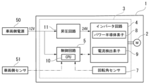
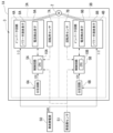
- FIG. 1 is a block diagram showing an electric power steering device 1 according to the first embodiment.
- An electric power steering device 1 shown in FIG. 1 includes a motor 2 that generates a steering assist force, and a control device 3 that controls the motor 2.
- Motor 2 in this embodiment is a three-phase brushless motor.
- the control device 3 is electrically connected to a vehicle-side power source 50 and a vehicle-side sensor 51 mounted on the vehicle. That is, the vehicle-side power supply 50 and the vehicle-side sensor 51 are provided outside the electric power steering device 1.
- the vehicle-side power source 50 is, for example, a battery, and supplies 24V (first voltage) DC power to the control device 3.
- Specific examples of the vehicle-side sensor 51 include a vehicle speed sensor that detects the speed of the vehicle, a torque sensor that detects the steering torque of a steering wheel, and the like.
- the control device 3 includes an inverter circuit 4, a control circuit 5, a voltage dividing circuit 6 (step-down circuit), and a rotation angle sensor 7.
- the inverter circuit 4 is controlled by the control circuit 5 and is configured to supply and cut off current to the motor 2.
- the inverter circuit 4 in this embodiment is configured to be supplied with 24V power from the vehicle-side power source 50 and driven by this power.
- the voltage supplied from the vehicle-side power source 50 is not necessarily constant, and the inverter circuit 4 is configured to operate appropriately at a voltage of, for example, 20 V or more and 32 V or less. ing.
- the inverter circuit 4 includes a plurality of power semiconductor elements 8 that function as switching elements and a current detection element 9 that detects the magnitude of current. Although not shown, the inverter circuit 4 includes a plurality of ripple capacitors that absorb ripples in the current flowing through the motor 2. As an example of the power semiconductor element 8, an FET (Field Effect Transistor) can be used. A plurality of bridge circuits are configured by a plurality of switching elements, and each bridge circuit is configured to supply current to each of the three-phase (U, V, W) windings of the motor 2.
- the current detection element 9 may be, for example, a shunt resistor.
- the control circuit 5 has a CPU 10 that performs arithmetic processing.
- the control circuit 5 includes a drive circuit used by the CPU 10 to control switching of the inverter circuit 4, an input circuit that transmits signals from the rotation angle sensor 7 and the vehicle-side sensor 51 to the CPU 10, and adjusts voltage. It may also include a regulator circuit or the like.
- Each function of the CPU 10, drive circuit, input circuit, and regulator circuit can be realized by, for example, an IC (Integrated Circuit) or an ASIC (Application Specific Integrated Circuit).
- the CPU 10 is configured to obtain various input signals, and specific examples of the input signals include information from the vehicle-side sensor 51, voltages of various parts in the inverter circuit 4, and motor detected by the current detection element 9. 2, the magnitude of the drive current, the detection result of the rotation angle by the rotation angle sensor 7, etc.
- the voltage divider circuit 6 is a circuit (step-down circuit) that generates a lower voltage of 12V (second voltage) from a voltage of 24V supplied from the vehicle-side power supply 50.
- the voltage dividing circuit 6 is composed of, for example, two resistors.
- the voltage dividing circuit 6 is electrically connected to the control circuit 5 and supplies the generated 12V voltage to the control circuit 5.
- a regulator or a step-down type A DC/DC converter may be provided instead of the voltage divider circuit 6, in order to generate a lower voltage (second voltage) from the 24V voltage (first voltage) supplied from the vehicle side power supply 50.
- the rotation angle sensor 7 is used to detect the rotation angle of the motor 2.
- the rotation angle sensor 7 in this embodiment detects the rotation angle of the motor 2 based on changes in magnetism.
- the rotation angle sensor 7 is supplied with power adjusted to an appropriate voltage by the voltage dividing circuit 6 or the regulator circuit.
- the control device 3 may include a power relay that can cut off power supply to the inverter circuit 4 and a noise filter connected to the vehicle-side power source 50.
- the power supply relay is used to protect the inverter circuit 4 from erroneous connection of the vehicle-side power supply 50 to the control device 3.
- An FET which is a switching element, can also be used for the power relay.
- a noise filter When a noise filter is provided, the power supplied from the vehicle-side power supply 50 is supplied to the inverter circuit 4 and the voltage dividing circuit 6 after passing through the noise filter.
- the noise filter may include a multilayer ceramic capacitor and a choke coil.
- the CPU 10 calculates the magnitude of the drive current to be supplied to each winding of the motor 2 based on the acquired input signal. Based on the calculation result, the CPU 10 controls switching of the inverter circuit 4. More specifically, the CPU 10 issues control instructions to the drive circuit.
- the drive circuit controls the power semiconductor element 8, which functions as a switching element, based on control instructions from the CPU 10. Control of the CPU 10 via the drive circuit is performed for each phase (U, V, W) of the motor 2. That is, the power semiconductor elements 8 of each phase (U, V, W) are driven by the drive circuit, so that a predetermined current flows to each winding of the motor 2.
- the magnitude of the current value supplied to each winding of the motor 2 is provided to the CPU 10 as an actual current value via the current detection element 9.
- the CPU 10 executes feedback control according to the deviation between the calculated value (target value) and the actual current value.
- the CPU 10 uses the rotation angle information obtained by the rotation angle sensor 7 to control the rotation of the motor 2.
- the CPU 10 uses the rotation angle information obtained by the rotation angle sensor 7 to calculate the rotation angle (phase) or rotation speed of the rotation shaft 21 of the motor 2.
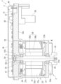
- FIG. 2 is a sectional view showing the electric power steering device 1 according to the first embodiment.
- the direction in which the central axis O of the rotating shaft 21 of the motor 2 extends may be referred to as the axial direction.
- the axial direction is also the thickness direction of the circuit board 31 in the control device 3.
- the side where the control device 3 is located is sometimes referred to as the upper side, and the side where the motor 2 is located is sometimes referred to as the lower side.
- Viewing from the axial direction is sometimes called planar view.
- plan view the direction intersecting the central axis O is sometimes referred to as the radial direction, and the direction going around the central axis O is sometimes referred to as the circumferential direction.
- the lower end of the rotating shaft 21 in the motor 2 is used as the output end 21a.
- a boss 22 connected to a driving object (for example, a steering system of a vehicle) is attached to the output end 21a.
- a speed reducer or the like may be interposed between the output end 21a and the driven object.
- the output of the motor 2 is transmitted to the driven object via the output end 21a. Note that when using the electric power steering device 1, the axial direction of the rotating shaft 21 does not need to coincide with the vertical direction.
- the motor 2 includes a motor body M and a motor case 23.
- Motor case 23 has a cylindrical portion 23a, a bottom portion 23b, and a protruding portion 23c.
- the cylindrical portion 23a extends along the axial direction.
- the bottom portion 23b is provided to close the opening at the lower end of the cylindrical portion 23a.
- the protruding portion 23c protrudes radially outward from the upper end of the cylindrical portion 23a.
- the motor main body M is housed inside a cylindrical portion 23a of the motor case 23.
- Motor case 23 is made of metal. In consideration of heat dissipation and ease of molding, the specific material for the motor case 23 is preferably an aluminum alloy, for example.
- the motor case 23 is manufactured, for example, by cutting a molded body obtained by die-casting or the like from an aluminum alloy.
- a through hole through which the rotating shaft 21 passes is formed in the center of the bottom portion 23b of the motor case 23.
- a first bearing 25 that rotatably supports the rotating shaft 21 is attached to the through hole of the bottom portion 23b.
- the motor main body M includes a rotor 26 and a stator 27.
- the rotor 26 includes a cylindrical rotor core 26a provided around the rotating shaft 21 and fixed to the rotating shaft 21, and a plurality of permanent magnets 26b provided on the outer peripheral surface of the rotor core 26a. There is.
- the plurality of permanent magnets 26b are arranged so that the polarities (S pole and N pole) on the outer circumferential surface of the rotor 26 alternate along the circumferential direction.
- the stator 27 is arranged radially outward of the rotor 26 with a gap therebetween.
- the stator 27 includes a stator core 27a made of laminated steel plates, and a winding 27b wound around the stator core 27a via an insulator 27c.
- the stator 27 is fixed within the cylindrical portion 23a of the motor case 23 by press fitting, shrink fitting, or the like.
- the rotating shaft 21, the rotor 26, and the stator 27 are arranged coaxially.
- connection ring 28 is arranged above the stator 27 and close to the winding 27b.
- the connection ring 28 has a structure in which a bus bar 29 (see FIG. 3) for electrical wiring is insert molded into an insulating resin.
- An end of each winding 27b is connected to the bus bar 29 of the connection ring 28, thereby forming a three-phase winding.
- Bus bars 29 for each phase protrude from the connection ring 28 and extend toward the control device 3 side.
- Three bus bars 29 are provided on the connection ring 28 to correspond to each phase (U, V, W). Each bus bar 29 protrudes upward from the connection ring 28 and is arranged to penetrate the circuit board 31 of the control device 3 .
- a disk-shaped heat sink 32 is fitted into the upper end of the cylindrical portion 23a of the motor case 23.
- the heat sink 32 is arranged with its central axis parallel to the axial direction.
- the height of the top surface of the heat sink 32 is equivalent to the height of the top surface of the protrusion 23c of the motor case 23.
- the upper surface of the heat sink 32 is formed into a flat shape and is flush with the upper surface of the protrusion 23c.
- the heat sink 32 is made of metal (for example, an aluminum alloy).
- the motor case 23 has a thickness greater than, for example, the thickness of the bottom portion 23b of the motor case 23 in the axial direction in order to ensure a relatively large heat capacity.
- a through hole 32a penetrating in the thickness direction is formed in the center of the heat sink 32, and a second bearing 33 (bearing) that rotatably supports the rotating shaft 21 is attached to the through hole 32a.
- the second bearing 33 supports an end 21b (upper end in this embodiment) of the rotating shaft 21 opposite to the output end 21a.
- the end portion 21 b of the rotating shaft 21 is arranged in the through hole 32 a of the heat sink 32 .
- the rotation angle sensor 7 is provided on the lower surface of the circuit board 31 and is disposed at a position facing the through hole 32a of the heat sink 32. Although the rotation angle sensor 7 protrudes downward from the lower surface of the circuit board 31, it does not interfere with the heat sink 32 because it is disposed within the through hole 32a of the heat sink 32.
- the heat sink 32 is formed with three through holes (not shown) through which the bus bars 29 of each phase (U, V, W) are passed.
- Both ends of the rotating shaft 21 are rotatably supported by a first bearing 25 and a second bearing 33. Therefore, the rotor 26 fixed to the rotating shaft 21 is also rotatable inside the stator 27 in the radial direction.
- a sensor magnet 34 is attached to the end 21b of the rotating shaft 21 on the opposite side from the output end 21a.
- the sensor magnet 34 is formed at least partially by a permanent magnet and emits a magnetic field.
- the sensor magnet 34 rotates together with the rotating shaft 21.
- the sensor magnet 34 also rotates, so the magnetic field changes.
- the sensor magnet 34 is arranged to face the rotation angle sensor 7 in the axial direction. Therefore, the rotation angle sensor 7 detects the rotation angle of the rotation shaft 21 of the motor 2 based on changes in the magnetic field generated by the sensor magnet 34 that rotates together with the rotation shaft 21.
- the control device 3 includes a circuit board 31 and an electronic circuit 35 provided on the circuit board 31.
- the circuit board 31 is, for example, a multilayer printed board in which a plurality of insulating layers and a plurality of conductor layers are laminated.
- Electronic circuit 35 includes inverter circuit 4, control circuit 5, and voltage divider circuit 6 shown in FIG.
- Electronic components such as a rotation angle sensor 7, a power semiconductor element 8, a current detection element 9, and a CPU 10 are mounted on the circuit board 31. These electronic components and the circuit pattern formed on the circuit board 31 constitute an electronic circuit 35.
- the circuit board 31 is covered from above by a cover 36.
- the cover 36 is configured to cover the circuit board 31.
- the circuit board 31 is housed in a space surrounded by the cover 36 and the motor case 23.
- the cover 36 has functions such as protecting the circuit board 31 from external electromagnetic noise and preventing electromagnetic noise generated from the circuit board 31 from leaking outside the cover 36. In order to exhibit these functions, it is desirable that the cover 36 be made of metal. In this embodiment, cover 36 is made of resin and metal.
- a connector 30 is provided on the lower surface of the protrusion 23c of the motor case 23.
- the connector 30 is used to connect the electric power steering device 1 to a vehicle-side power source 50 and a vehicle-side sensor 51.
- a plurality of connector terminals 43 are provided above the connector 30.
- Connector terminal 43 is electrically connected to a terminal (not shown) within connector 30.
- the protruding portion 23c of the motor case 23 is provided with an opening (not shown) through which the connector terminal 43 passes, and the connector terminal 43 is inserted into the inside of this opening. Further, a connector terminal 43 is inserted into a through hole formed in the circuit board 31, and the circuit pattern of the circuit board 31 and the connector terminal 43 are electrically connected by soldering.
- the method of connecting the circuit board 31 and the connector terminal 43 is not limited to soldering, and for example, press-fit may be used. Electric power from a vehicle-side power source 50 and signals from a vehicle-side sensor 51 are transmitted to the circuit board 31 via the connector 30 .
- the connector 30 is provided on the lower surface of the protrusion 23c, but the present invention is not limited to this. A hole is formed in the cover 36, and the connector is connected to the upper surface of the circuit board 31 from above through the hole. It is also possible to attach 30.
- No electronic components other than the rotation angle sensor 7 are mounted on the lower surface of the circuit board 31.
- the lower surface of the circuit board 31 is arranged in contact with the surface of the heat sink 32 on the opposite side from the motor 2 (the upper surface in this embodiment). More specifically, the lower surface of the circuit board 31 is in contact with the upper surface of the heat sink 32 via applied insulating grease (not shown in FIG. 2). It is preferable to select a grease that has high thermal conductivity.
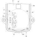
- FIG. 3 is a plan view of the circuit board 31.
- FIG. 3 shows the top surface of the circuit board 31.
- the circuit board 31 is fixed to the motor case 23 with a plurality of screws 37.
- Three bus bars 29 corresponding to each phase are connected to the circuit board 31 so as to penetrate through the circuit board 31 in the board thickness direction.
- the bus bar 29 is connected to a circuit pattern (not shown) on the circuit board 31 by soldering, and this circuit pattern is electrically connected to the winding 27b of the motor 2 via the bus bar 29.
- the circuit pattern of the circuit board 31 and the bus bars 29 of each phase may be connected not only by soldering but also by press-fitting, for example.
- a virtual area obtained by projecting the outer shape of the heat sink 32 onto the circuit board 31 is referred to as a projection area 42.
- the circuit board 31 protrudes outside the projection area 42 when viewed from the axial direction.
- the protruding portion 23c of the motor case 23 also protrudes radially outward from the cylindrical portion 23a so as to support the portion of the circuit board 31 that protrudes from the projection area 42.
- the power semiconductor element 8, the current detection element 9, etc. mounted on the circuit board 31 are heat generating elements that generate heat when a large current is passed through them as the motor 2 is driven. In order not to shorten the continuous use time of the electric power steering device 1 and to prevent a decrease in the steering assist force, it is preferable that the heat generated by these heating elements is quickly released to the outside of the electric power steering device 1. .
- the power semiconductor element 8 and the current detection element 9 are arranged on the upper surface of the circuit board 31. Further, the power semiconductor element 8 and the current detection element 9 are arranged within the projection area 42 of the circuit board 31. That is, the power semiconductor element 8 and the current detection element 9 are arranged in line with the heat sink 32 in the axial direction.
- a voltage of 12V was generally supplied to the electric power steering device from the vehicle side power supply, but in this embodiment, a voltage of 24V is supplied from the vehicle side power supply 50 to the inverter circuit 4 of the control device 3. Therefore, when the input power to the motor 2 is made equal to that of the conventional motor, the voltage is twice that of the conventional motor, so the current can be halved. Therefore, it is possible to suppress heat generation in the power semiconductor elements 8 such as FETs in the inverter circuit 4.
- the effect of suppressing the amount of heat generated is not limited to the power semiconductor elements 8 such as FETs mounted on the circuit board 31, but also to the current detection elements 9, ripple capacitors, power relays, choke coils, etc. that reduce the current. A similar effect is produced on all possible heating elements. Moreover, heat generation in the bus bar 29 and the winding 27b of the motor 2 can be similarly suppressed. Since the amount of heat generated by the power semiconductor element 8 and the current detection element 9 can be suppressed, a simplified heat dissipation structure using the heat sink 32 of this embodiment can be adopted. As described above, the power semiconductor element 8 and the current detection element 9 are arranged on the upper surface of the circuit board 31 and within the projection area 42 .
- the heat generated by the heat generating element is transferred to the heat sink through the circuit board 31 and the grease. 32 to the outside. Since the amount of heat generated by the heating element can be suppressed, the heat dissipation structure can be downsized and simplified, the weight of the electric power steering device 1 can be suppressed, and it can be manufactured at a lower cost.
- a voltage of 24V is supplied from the vehicle-side power supply 50 to the control device 3; however, the present invention is not limited to this; for example, a voltage of 48V is supplied from the vehicle-side power supply 50 to the control device 3 and the inverter circuit. 4 may be supplied.
- the input power to the motor 2 is the same as that of the conventional motor, the voltage is four times that of the conventional motor, so the current can be reduced to 1/4, and the amount of heat generated by the heating element can be further suppressed.
- the inverter circuit 4 can operate at a voltage of, for example, 42 V or more and 56 V or less. configured for proper operation. From the above, in order to suppress the amount of heat generated, the inverter circuit 4 may be configured to be driven at a voltage of 20 V or more and 56 V or less. Furthermore, although the control circuit 5 in this embodiment operates at a voltage of 12V, the withstand voltage performance of the electronic components constituting the control circuit 5 is increased so that it operates at a voltage of 24V like the inverter circuit 4. It is also possible to configure In this case, there is no need to supply the voltage of 12V to the control circuit 5 from the voltage dividing circuit 6 described above.
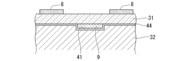
- FIG. 4 is a plan view of the circuit board 31 according to the first modification of the first embodiment.
- 5 is a sectional view taken along the line VV in FIG. 4.
- a recess 41 in which the current detection element 9 is accommodated is formed at a position facing the current detection element 9. Therefore, as in the first embodiment, the lower surface of the circuit board 31 other than the current detection element 9 can be brought close to the upper surface of the heat sink 32.
- the gap between the bottom surface of the circuit board 31 and the top surface of the heat sink 32 and the inside of the recess 41 are filled with grease 44 to form a heat radiation path.
- FIG. 6 is a plan view of the circuit board 31 according to the second modification of the first embodiment.
- 7 is a sectional view taken along the line VII-VII in FIG. 6.
- a plurality of thermal vias 45 for heat radiation are arranged around the power semiconductor element 8 on the circuit board 31 .
- the thermal via 45 is arranged on the circuit board 31 around the power semiconductor element 8 and at a different position from the power semiconductor element 8 in plan view.
- the thermal via 45 has a configuration in which the inner surface of a through hole that penetrates through the circuit board 31 in the board thickness direction is plated with a metal such as copper or gold that has good thermal conductivity.
- the heat of the power semiconductor element 8 can be more efficiently transmitted from the upper surface of the circuit board 31 to the heat sink 32 via the metal plating of the thermal via 45. It is possible to improve heat dissipation performance.
- a circuit pattern extending in the plane direction along the upper surface of the circuit board 31 may be formed to connect the thermal via 45 and the power semiconductor element 8, or a circuit pattern may be formed on the lower surface of the circuit board 31 to connect the thermal via 45 and the power semiconductor element 8.
- a circuit pattern extending in the plane direction from the thermal via 45 may be formed. By forming such a circuit pattern, the heat of the power semiconductor element 8 can be more efficiently released through the thermal via 45. Further, the thermal via 45 may be formed around a heating element other than the power semiconductor element 8.
- FIG. 8 is a plan view of the circuit board 31 according to the third modification of the first embodiment.
- FIG. 9 is a sectional view taken along the line IX-IX in FIG.
- a copper inlay 46 is arranged on the circuit board 31 at a position between the power semiconductor element 8 and the heat sink 32 in the axial direction.
- the copper inlay 46 has a configuration in which an inlay made of copper having good thermal conductivity is placed in a through hole penetrating the circuit board 31 in the board thickness direction.
- the upper surface of the copper inlay 46 is in contact with the lower surface of the power semiconductor element 8.
- the heat of the power semiconductor element 8 can be more efficiently transmitted toward the heat sink 32 via the copper inlay 46, and heat dissipation performance can be improved.
- the copper inlay 46 may be arranged between a heat generating element other than the power semiconductor element 8 and the heat sink 32.
- FIG. 10 is a block diagram showing an electric power steering device 1 according to a fourth modification of the first embodiment.
- This modification differs from the configuration of the first embodiment in that the vehicle-side power supply 50 supplies 12V power to the control device 3 of the electric power steering device 1, and the control device 3 is different from the configuration of the first embodiment described above. 1 is provided with a booster circuit 11 in place of the voltage divider circuit 6 in FIG.
- a voltage of 12V (second voltage) supplied from the vehicle-side power supply 50 is supplied to the control circuit 5 and the booster circuit 11.
- the control circuit 5 is driven by a voltage of 12V supplied from the outside.
- the booster circuit 11 generates a higher voltage of 24V (first voltage) from a voltage of 12V supplied from the outside.
- a DC/DC converter can be used as the booster circuit 11, for example.
- the 24V voltage generated by the booster circuit 11 is supplied to the inverter circuit 4, and the inverter circuit 4 is driven by the 24V voltage generated by the booster circuit 11.
- the amount of heat generated is proportional to the square of the current value, so the output voltage of the booster circuit 11 is further increased to, for example, 48V, while the current in the inverter circuit 4 is further decreased to reduce the amount of heat generated. It may be further reduced.
- the booster circuit 11 may output a voltage of 20V or more, for example.
- the inverter circuit 4 may also be configured to be driven by a voltage of 20V or more. According to this modification, measures can be taken to reduce the amount of heat generated in the electric power steering device 1 without changing the configuration of the vehicle-side power source 50 from the conventional one.
- the first voltage which is the voltage at which the inverter circuit 4 is driven
- the second voltage which is the voltage at which the control circuit 5 is driven
- the first voltage may be 20V or higher.
- the second voltage which is the voltage at which the control circuit 5 is driven
- the first voltage and the second voltage may be lower than the first voltage and at least a voltage at which the control circuit 5 can operate properly.
- the electric power steering device 1 includes the motor 2, the heat sink 32 provided with the second bearing 33 that rotatably supports the rotating shaft 21 of the motor 2, and the motor 2.
- An inverter circuit 4 for driving is provided, and a circuit board 31 is provided on the opposite side of the heat sink 32 from the motor 2.
- the power semiconductor element 8 and the current detection element 9 that constitute the inverter circuit 4 are arranged in a projection area 42 on the circuit board 31 on which the outer shape of the heat sink 32 is projected, when viewed from the axial direction of the rotation shaft 21.
- the inverter circuit 4 is configured to be driven by a first voltage of 20V or higher.
- the power semiconductor element 8 and the current detection element 9 are arranged within the projection area 42 of the circuit board 31. Therefore, even in a simplified heat dissipation structure in which the lower surface of the circuit board 31 is in contact with the upper surface of the heat sink 32 through the grease, the heat generated by the heat generating element is transferred to the heat sink through the circuit board 31 and the grease. 32 to the outside. Since the amount of heat generated by the heating element can be suppressed, the heat dissipation structure can be downsized and simplified, the weight of the electric power steering device 1 can be suppressed, and it can be manufactured at a lower cost.
- the circuit board 31 also includes a voltage divider circuit 6 (step-down circuit) that generates a second voltage lower than the first voltage from a first voltage supplied from the outside, and a voltage divider circuit 6 (step-down circuit) that generates a second voltage lower than the first voltage.
- a control circuit 5 that drives the inverter circuit 4 with the second voltage and controls the inverter circuit 4 may also be provided. According to this configuration, since the control circuit 5 is driven with the second voltage lower than the first voltage, the withstand voltage performance of the electronic components constituting the control circuit 5 is not improved. Additionally, a configuration that operates at a voltage of 12V can be adopted, and an increase in the cost of electronic components due to changes in voltage resistance can be avoided.
- the circuit board 31 is provided with a boost circuit 11 that generates the first voltage from a second voltage lower than the first voltage supplied from the outside, and the inverter circuit 4 is connected to the boost circuit 11 that generates the first voltage.
- the first voltage may be used.
- the circuit board 31 is provided with a control circuit 5 that controls the inverter circuit 4, and the control circuit 5 may be driven by a second voltage supplied from the outside.
- control circuit 5 since the control circuit 5 is driven with the second voltage lower than the first voltage, the withstand voltage performance of the electronic components constituting the control circuit 5 is not improved. Additionally, a configuration that operates at a voltage of 12V can be adopted, and an increase in the cost of electronic components due to changes in voltage resistance can be avoided.
- the heating elements constituting the inverter circuit 4 include a current detection element 9 provided on the surface of the circuit board 31 facing the heat sink 32, and a current detection element 9 is provided at a position facing the current detection element 9 of the heat sink 32.
- a recess 41 may be formed in which the number 9 is accommodated. According to this configuration, it is difficult to mount the current detection element 9 on the upper surface of the circuit board 31 due to restrictions on the mounting area, etc., and even when mounted on the lower surface of the circuit board 31, the current detection element 9 is mounted in the recess 41. By accommodating the element 9, it becomes possible to bring the surface of the circuit board 31 other than the current detection element 9 into close contact with the heat sink 32, and it is possible to maintain high heat transfer efficiency between the circuit board 31 and the heat sink 32. .
- thermal vias 45 for heat radiation may be arranged around heat generating elements such as the power semiconductor element 8 and the current detection element 9. According to this configuration, the heat generated by the heating element can be efficiently transmitted from the heating element mounting surface of the circuit board 31 to the opposite surface via the thermal via 45, thereby improving heat dissipation efficiency. can.
- a copper inlay 46 may be arranged at a position between the heat sink 32 and heat generating elements such as the power semiconductor element 8 and the current detection element 9 in the axial direction. According to this configuration, the heat generated by the heating element can be efficiently transmitted from the heating element mounting surface of the circuit board 31 to the opposite surface via the copper inlay 46, thereby improving heat dissipation efficiency. can.
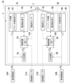
- FIG. 11 is a block diagram showing an electric power steering device 1A according to the second embodiment.
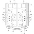
- FIG. 12 is a plan view of the circuit board 31 according to the second embodiment.
- the structure of the motor 2 in this embodiment is similar to the structure of the motor 2 according to the first embodiment. Therefore, components of the motor 2 that are the same as those in the first embodiment are given the same reference numerals, and the explanation thereof is omitted, and the explanation will focus on the different points.
- the control device 3 in this embodiment includes two control units 3A and 3B.
- the stator 27 of the motor 2 in this embodiment has two sets of three-phase windings (not shown).
- the first control unit 3A is configured to control the first three-phase winding
- the second control unit 3B is configured to control the second three-phase winding.
- the control units 3A and 3B have mutually equivalent circuit configurations. Further, each of the control units 3A and 3B has substantially the same circuit configuration as the control device 3 described in the first embodiment. Therefore, in this embodiment, among the components of the first control unit 3A, the suffix "A” is attached to the same reference numerals as the corresponding components in the first embodiment. Further, among the components of the second control unit 3B, the suffix "B" is attached to the same reference numerals as the corresponding components in the first embodiment.
- control unit 3A includes a control circuit 5A and an inverter circuit 4A.
- the configurations of control circuit 5A and inverter circuit 4A are similar to the configurations of control circuit 5 and inverter circuit 4 described in the first embodiment.
- the mounting area of the circuit board 31 in this embodiment is divided into two areas corresponding to the control units 3A and 3B, and the electronic components included in the control units 3A and 3B are also divided into two areas. They are placed in two areas.
- a plurality of power semiconductor elements 8A, a plurality of current detection elements 9A, a CPU 10A, and three bus bars 29A are arranged in the area indicated by the symbol 3A, and a plurality of power semiconductor elements 8B and a plurality of current detection elements 8B are disposed in the region indicated by the symbol 3B.
- a detection element 9B, a CPU 10B, and three bus bars 29B are arranged.
- FIG. 12 illustrations of electronic components such as ripple capacitors, choke coils, and power supply relays are omitted.
- the motor 2 is a brushless motor with three phases and two sets of windings.
- the electric power steering device 1A includes rotation angle sensors 7A and 7B for detecting the rotation angle of the motor 2.
- the rotation angle signal output by the first rotation angle sensor 7A is input to the control circuit 5A of the first control unit 3A, and the rotation angle signal output by the second rotation angle sensor 7B is input to the control circuit 5A of the first control unit 3A. It is input to circuit 5B.
- the control units 3A and 3B can each independently drive the motor 2. That is, the inverter circuits 4A and 4B each drive the motor 2. However, the control units 3A and 3B are each supplied with a current obtained by dividing the current output from the vehicle-side power source 50 into two, and the same signal output from the vehicle-side sensor 51 is input to both. For example, in the first control unit 3A, the first control circuit 5A and the first inverter circuit 4A operate based on input information from the vehicle-side sensor 51, the first rotation angle sensor 7A, and the like. As a result, the rotating shaft 21 is driven via the first winding.
- the second control circuit 5B and the second inverter circuit 4B operate based on input information from the vehicle-side sensor 51, the second rotation angle sensor 7B, and the like. Thereby, the rotating shaft 21 is driven via the second winding.
- the two control units 3A and 3B By configuring the two control units 3A and 3B to drive the motor 2 independently of each other in this way, redundancy is ensured. For example, even if a problem occurs in one of the control units 3A, 3B and the motor 2 cannot be driven, the drive of the motor 2 can be maintained by the other control unit 3A, 3B, so the steering assist force becomes completely zero. Furthermore, since the driver who is operating the steering wheel can sense the decrease in the steering assist force, the driver can quickly recognize the occurrence of the problem.
- the current supplied to each of the inverter circuits 4A and 4B is 1/2 of the current in the first embodiment, the heat generated by the heating elements of each inverter circuit 4A and 4B is lower than that in the first embodiment. can be reduced.
- FIG. 13 is a block diagram showing an electric power steering device 1B according to a modification of the second embodiment.
- the control units 3A and 3B are each supplied with a current obtained by dividing the current outputted by the vehicle-side power source 50 into two, and the same signal outputted by the vehicle-side sensor 51 is supplied to the control units 3A and 3B.
- vehicle-side power supplies 50A, 50B and vehicle-side sensors 51A, 51B which correspond to control units 3A, 3B, respectively, are used.
- the first vehicle-side power supply 50A supplies power to the first control unit 3A
- the second vehicle-side power supply 50B supplies power to the second control unit 3B.
- the first control circuit 5A and the first inverter circuit 4A operate based on input information from the first vehicle-side sensor 51A, the first rotation angle sensor 7A, etc. do.
- the second control circuit 5B and the second inverter circuit 4B operate based on input information from the second vehicle-side sensor 51B, the second rotation angle sensor 7B, etc. Operate.
- two connectors are also provided for connecting the circuit board 31 of this modification to the vehicle-side power supplies 50A, 50B and the vehicle-side sensors 51A, 51B.
- the vehicle-side power supplies 50A and 50B supply power to the control units 3A and 3B separately, but the current supplied by the vehicle-side power supplies 50A and 50B is the same as that of the vehicle-side power supply 50 shown in FIG. This is 1/2 of the supplied current. Therefore, also in this modification, the current supplied to each of the inverter circuits 4A and 4B is 1/2 of the current in the first embodiment, so that the heat generated by the heating elements of each inverter circuit 4A and 4B is reduced. , can be reduced compared to the first embodiment.
- the two inverter circuits 4A and 4B each drive the motor 2, and a two-system configuration is adopted; however, the number of inverter circuits is not limited to two, and the number of inverter circuits provided is not limited to two.
- the number of circuits may be three or more, and each circuit may be configured to drive the motor 2.
- a four-system configuration may be adopted.
- the present disclosure is not limited to the configurations of the embodiments and modifications described above, but is limited only by the scope of the claims. It is possible to combine the modified examples described in each embodiment with each other, or to modify or omit the configuration according to each embodiment as appropriate.
- the second embodiment is explained based on the control device 3 shown in FIG. 1 of the first embodiment, the modifications 1 to 4 of the first embodiment are different from the second embodiment. It is also possible to apply the control device 3 described.
Abstract
La présente invention concerne un dispositif de direction assistée électrique (1, 1A, 1B) qui comprend : un moteur (2) ; un dissipateur thermique (32) pourvu d'un palier (33) qui supporte un arbre rotatif (21) du moteur en rotation ; et un substrat de circuit (31) qui est pourvu d'un circuit onduleur (4, 4A, 4B) pour entraîner le moteur et qui est disposé sur une surface du dissipateur thermique sur le côté opposé au moteur. Des éléments chauffants (8, 8A, 8B, 9, 9A, 9B) constituant le circuit onduleur sont agencés à l'intérieur d'un domaine de projection (42) qui est formé sur le substrat de circuit et sur lequel la forme externe du dissipateur thermique est projetée, tel que vu depuis la direction axiale de l'arbre rotatif. Le circuit onduleur est conçu pour être entraîné à une première tension de 20 V ou plus.
Priority Applications (1)
| Application Number | Priority Date | Filing Date | Title |
|---|---|---|---|
| PCT/JP2022/018808 WO2023209787A1 (fr) | 2022-04-26 | 2022-04-26 | Dispositif de direction assistée électrique |
Applications Claiming Priority (1)
| Application Number | Priority Date | Filing Date | Title |
|---|---|---|---|
| PCT/JP2022/018808 WO2023209787A1 (fr) | 2022-04-26 | 2022-04-26 | Dispositif de direction assistée électrique |
Publications (1)
| Publication Number | Publication Date |
|---|---|
| WO2023209787A1 true WO2023209787A1 (fr) | 2023-11-02 |
Family
ID=88518134
Family Applications (1)
| Application Number | Title | Priority Date | Filing Date |
|---|---|---|---|
| PCT/JP2022/018808 WO2023209787A1 (fr) | 2022-04-26 | 2022-04-26 | Dispositif de direction assistée électrique |
Country Status (1)
| Country | Link |
|---|---|
| WO (1) | WO2023209787A1 (fr) |
Citations (7)
| Publication number | Priority date | Publication date | Assignee | Title |
|---|---|---|---|---|
| JP2003289696A (ja) * | 2002-03-27 | 2003-10-10 | Mitsubishi Electric Corp | 電動機駆動装置及び空気調和機の駆動装置 |
| JP2010051111A (ja) * | 2008-08-22 | 2010-03-04 | Denso Corp | モータ駆動装置 |
| WO2017094589A1 (fr) * | 2015-11-30 | 2017-06-08 | 日本精工株式会社 | Substrat de dissipation de chaleur et dispositif de direction assistée à entraînement électrique |
| JP2017147259A (ja) * | 2016-02-15 | 2017-08-24 | 株式会社デンソー | 電子装置およびその検査方法 |
| WO2017158966A1 (fr) * | 2016-03-18 | 2017-09-21 | 三菱電機株式会社 | Dispositif de commande de direction assistée électrique |
| WO2017175325A1 (fr) * | 2016-04-06 | 2017-10-12 | 三菱電機株式会社 | Dispositif de direction assistée électrique |
| WO2019070064A1 (fr) * | 2017-10-06 | 2019-04-11 | 日本電産株式会社 | Module de moteur et appareil de direction assistée électrique |
-
2022
- 2022-04-26 WO PCT/JP2022/018808 patent/WO2023209787A1/fr unknown
Patent Citations (7)
| Publication number | Priority date | Publication date | Assignee | Title |
|---|---|---|---|---|
| JP2003289696A (ja) * | 2002-03-27 | 2003-10-10 | Mitsubishi Electric Corp | 電動機駆動装置及び空気調和機の駆動装置 |
| JP2010051111A (ja) * | 2008-08-22 | 2010-03-04 | Denso Corp | モータ駆動装置 |
| WO2017094589A1 (fr) * | 2015-11-30 | 2017-06-08 | 日本精工株式会社 | Substrat de dissipation de chaleur et dispositif de direction assistée à entraînement électrique |
| JP2017147259A (ja) * | 2016-02-15 | 2017-08-24 | 株式会社デンソー | 電子装置およびその検査方法 |
| WO2017158966A1 (fr) * | 2016-03-18 | 2017-09-21 | 三菱電機株式会社 | Dispositif de commande de direction assistée électrique |
| WO2017175325A1 (fr) * | 2016-04-06 | 2017-10-12 | 三菱電機株式会社 | Dispositif de direction assistée électrique |
| WO2019070064A1 (fr) * | 2017-10-06 | 2019-04-11 | 日本電産株式会社 | Module de moteur et appareil de direction assistée électrique |
Similar Documents
| Publication | Publication Date | Title |
|---|---|---|
| CN109720404B (zh) | 负载驱动装置 | |
| CN108137084B (zh) | 一体型电动助力转向装置及其制造方法 | |
| JP5039171B2 (ja) | 電動式駆動装置およびその電動式駆動装置を搭載した電動式パワーステアリング装置 | |
| JP6160576B2 (ja) | 駆動装置、および、これを用いた電動パワーステアリング装置 | |
| JP5970668B2 (ja) | 電動式パワーステアリング用パワーモジュールおよびこれを用いた電動式パワーステアリング駆動制御装置 | |
| JP5951067B1 (ja) | 電動パワーステアリング装置 | |
| JP5067679B2 (ja) | 半導体モジュール、および、それを用いた駆動装置 | |
| JP6444495B2 (ja) | 電動パワーステアリング駆動装置 | |
| JP5201171B2 (ja) | 半導体モジュール、および、それを用いた駆動装置 | |
| JP2011176998A (ja) | 駆動装置 | |
| KR20100122955A (ko) | 전동 파워 스티어링 장치, 및 제어 장치 일체형 전동기 | |
| US9622349B2 (en) | Control device, and motor unit including control device | |
| US11404941B2 (en) | Power conversion device | |
| JP2018061363A (ja) | モータ駆動装置、モータシステム及び電動パワーステアリング装置 | |
| JP2011083063A (ja) | 駆動制御装置、およびモータユニット | |
| JP6862570B2 (ja) | 電動パワーステアリング装置 | |
| JP6937897B2 (ja) | 電動パワーステアリング装置 | |
| US9398724B2 (en) | Control device and motor unit including the control device | |
| WO2023209787A1 (fr) | Dispositif de direction assistée électrique | |
| JP6870711B2 (ja) | 駆動装置、および、これを用いた電動パワーステアリング装置 | |
| JP7399351B2 (ja) | 制御装置、駆動装置、および電動パワーステアリング装置 | |
| US11728713B2 (en) | Power conversion device | |
| US20240136894A1 (en) | Control device, drive device, and electric power steering device | |
| JP6934985B1 (ja) | 回転電機 | |
| JP2011083065A (ja) | 駆動制御装置、およびモータユニット |
Legal Events
| Date | Code | Title | Description |
|---|---|---|---|
| 121 | Ep: the epo has been informed by wipo that ep was designated in this application |
Ref document number: 22940067 Country of ref document: EP Kind code of ref document: A1 |