WO2023209787A1 - Electric power steering device - Google Patents
Electric power steering device Download PDFInfo
- Publication number
- WO2023209787A1 WO2023209787A1 PCT/JP2022/018808 JP2022018808W WO2023209787A1 WO 2023209787 A1 WO2023209787 A1 WO 2023209787A1 JP 2022018808 W JP2022018808 W JP 2022018808W WO 2023209787 A1 WO2023209787 A1 WO 2023209787A1
- Authority
- WO
- WIPO (PCT)
- Prior art keywords
- circuit
- circuit board
- voltage
- motor
- electric power
- Prior art date
Links
- 238000001514 detection method Methods 0.000 claims description 38
- 238000010438 heat treatment Methods 0.000 claims description 27
- RYGMFSIKBFXOCR-UHFFFAOYSA-N Copper Chemical compound [Cu] RYGMFSIKBFXOCR-UHFFFAOYSA-N 0.000 claims description 12
- 229910052802 copper Inorganic materials 0.000 claims description 12
- 239000010949 copper Substances 0.000 claims description 12
- 230000005855 radiation Effects 0.000 claims description 4
- 239000000758 substrate Substances 0.000 abstract 2
- 239000004065 semiconductor Substances 0.000 description 36
- 238000012986 modification Methods 0.000 description 24
- 230000004048 modification Effects 0.000 description 24
- 230000017525 heat dissipation Effects 0.000 description 21
- 238000004804 winding Methods 0.000 description 16
- 239000004519 grease Substances 0.000 description 9
- 238000010586 diagram Methods 0.000 description 8
- 239000000463 material Substances 0.000 description 6
- 229910052751 metal Inorganic materials 0.000 description 6
- 239000002184 metal Substances 0.000 description 6
- 230000020169 heat generation Effects 0.000 description 5
- 230000000694 effects Effects 0.000 description 4
- 238000005476 soldering Methods 0.000 description 4
- 229910000838 Al alloy Inorganic materials 0.000 description 3
- 239000003990 capacitor Substances 0.000 description 3
- 238000007599 discharging Methods 0.000 description 2
- 230000000149 penetrating effect Effects 0.000 description 2
- 239000011347 resin Substances 0.000 description 2
- 229920005989 resin Polymers 0.000 description 2
- 229910000576 Laminated steel Inorganic materials 0.000 description 1
- 239000003985 ceramic capacitor Substances 0.000 description 1
- 239000003638 chemical reducing agent Substances 0.000 description 1
- 239000004020 conductor Substances 0.000 description 1
- 238000005520 cutting process Methods 0.000 description 1
- 230000003247 decreasing effect Effects 0.000 description 1
- 238000004512 die casting Methods 0.000 description 1
- 238000009429 electrical wiring Methods 0.000 description 1
- 230000005669 field effect Effects 0.000 description 1
- PCHJSUWPFVWCPO-UHFFFAOYSA-N gold Chemical compound [Au] PCHJSUWPFVWCPO-UHFFFAOYSA-N 0.000 description 1
- 229910052737 gold Inorganic materials 0.000 description 1
- 239000010931 gold Substances 0.000 description 1
- 239000012212 insulator Substances 0.000 description 1
- 230000005389 magnetism Effects 0.000 description 1
- 230000007257 malfunction Effects 0.000 description 1
- 238000004519 manufacturing process Methods 0.000 description 1
- 238000000034 method Methods 0.000 description 1
- 238000000465 moulding Methods 0.000 description 1
- 230000002093 peripheral effect Effects 0.000 description 1
- 238000007747 plating Methods 0.000 description 1
Images


Classifications
-
- B—PERFORMING OPERATIONS; TRANSPORTING
- B62—LAND VEHICLES FOR TRAVELLING OTHERWISE THAN ON RAILS
- B62D—MOTOR VEHICLES; TRAILERS
- B62D5/00—Power-assisted or power-driven steering
- B62D5/04—Power-assisted or power-driven steering electrical, e.g. using an electric servo-motor connected to, or forming part of, the steering gear
Definitions
- the present disclosure relates to an electric power steering device.
- Patent Document 1 discloses an electric power steering device that is attached to a vehicle and assists a driver's steering operation.
- An electric power steering device includes a control device configured to have an inverter circuit that drives a motor and a control circuit that controls the inverter circuit provided on a circuit board, and this control device is integrated with the motor.
- the inverter circuit includes power semiconductor elements such as switching elements, and the power semiconductor elements are heating elements that generate heat as the motor is driven.
- electronic components mounted on circuit boards may have an upper limit for their operating temperature, and when this upper limit is reached, the electric power steering system must be operated to prevent malfunction or damage to the electronic components. Measures such as suspending operations may be taken. In this case, the continuous use time of the electric power steering device may be shortened, leading to a decrease in steering assist force, so the electric power steering device is provided with a heat dissipation structure for dissipating the heat of the heating element.
- Patent Document 1 discloses a heat dissipation structure in which a heat dissipation material is provided between the other surface of a circuit board on which a heat generating element is mounted on one surface and a heat sink that constitutes a part of a motor casing, and the circuit board is By fixing screws to the housing, the heat dissipation material is brought into close contact with the circuit board and heat sink, and the heat generated by the heat generating elements of the circuit board is radiated to the heat sink via the heat dissipation material.
- This type of structure is designed to efficiently dissipate heat from the heating element, but it is necessary to secure an area for the circuit board and heat sink to be in close contact with the heat dissipation material, and by using the heat dissipation material, the device There were issues such as the size of the product becoming larger and the weight of the product increasing.
- the present disclosure was made in order to solve the above-mentioned problems, and by suppressing the heat generation amount of the heating element, the heat dissipation structure can be made smaller and simpler, the product weight can be reduced, and manufacturing can be made at low cost.
- the purpose of the present invention is to provide an electric power steering device with an integrated control device.
- An electric power steering device includes a motor, a heat sink provided with a bearing that rotatably supports a rotating shaft of the motor, and an inverter circuit that drives the motor.
- a circuit board disposed on the opposite surface, and the heating element constituting the inverter circuit is located within a projection area of the circuit board on which the outer shape of the heat sink is projected, when viewed from the axial direction of the rotation shaft.
- the inverter circuit is configured to be driven by a first voltage of 20V or more.
- the heat generation amount of the heating element can be suppressed, the heat dissipation structure can be downsized and simplified, the product weight can be suppressed, and the electric power steering device integrated with the control device can be manufactured at low cost. can be provided.
- FIG. 1 is a block diagram showing an electric power steering device according to Embodiment 1.
- FIG. 1 is a sectional view of an electric power steering device according to Embodiment 1.
- FIG. 1 is a plan view of a circuit board according to Embodiment 1.
- FIG. 7 is a plan view of a circuit board according to Modification 1 of Embodiment 1.
- FIG. 5 is a sectional view taken along the line VV in FIG. 4.
- FIG. 7 is a plan view of a circuit board according to a second modification of the first embodiment.
- FIG. 7 is a sectional view taken along the line VII-VII in FIG. 6.
- FIG. 7 is a plan view of a circuit board according to a third modification of the first embodiment.
- FIG. 1 is a block diagram showing an electric power steering device according to Embodiment 1.
- FIG. 1 is a sectional view of an electric power steering device according to Embodiment 1.
- FIG. 1 is a plan view of a circuit board according to Em
- FIG. 9 is a sectional view taken along the line IX-IX in FIG. 8.
- FIG. FIG. 7 is a block diagram showing an electric power steering device according to a fourth modification of the first embodiment.
- FIG. 2 is a block diagram showing an electric power steering device according to a second embodiment.
- FIG. 3 is a plan view of a circuit board according to a second embodiment.
- FIG. 3 is a block diagram showing an electric power steering device according to a modification of the second embodiment.
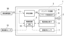
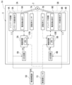
- FIG. 1 is a block diagram showing an electric power steering device 1 according to the first embodiment.
- An electric power steering device 1 shown in FIG. 1 includes a motor 2 that generates a steering assist force, and a control device 3 that controls the motor 2.
- Motor 2 in this embodiment is a three-phase brushless motor.
- the control device 3 is electrically connected to a vehicle-side power source 50 and a vehicle-side sensor 51 mounted on the vehicle. That is, the vehicle-side power supply 50 and the vehicle-side sensor 51 are provided outside the electric power steering device 1.
- the vehicle-side power source 50 is, for example, a battery, and supplies 24V (first voltage) DC power to the control device 3.
- Specific examples of the vehicle-side sensor 51 include a vehicle speed sensor that detects the speed of the vehicle, a torque sensor that detects the steering torque of a steering wheel, and the like.
- the control device 3 includes an inverter circuit 4, a control circuit 5, a voltage dividing circuit 6 (step-down circuit), and a rotation angle sensor 7.
- the inverter circuit 4 is controlled by the control circuit 5 and is configured to supply and cut off current to the motor 2.
- the inverter circuit 4 in this embodiment is configured to be supplied with 24V power from the vehicle-side power source 50 and driven by this power.
- the voltage supplied from the vehicle-side power source 50 is not necessarily constant, and the inverter circuit 4 is configured to operate appropriately at a voltage of, for example, 20 V or more and 32 V or less. ing.
- the inverter circuit 4 includes a plurality of power semiconductor elements 8 that function as switching elements and a current detection element 9 that detects the magnitude of current. Although not shown, the inverter circuit 4 includes a plurality of ripple capacitors that absorb ripples in the current flowing through the motor 2. As an example of the power semiconductor element 8, an FET (Field Effect Transistor) can be used. A plurality of bridge circuits are configured by a plurality of switching elements, and each bridge circuit is configured to supply current to each of the three-phase (U, V, W) windings of the motor 2.
- the current detection element 9 may be, for example, a shunt resistor.
- the control circuit 5 has a CPU 10 that performs arithmetic processing.
- the control circuit 5 includes a drive circuit used by the CPU 10 to control switching of the inverter circuit 4, an input circuit that transmits signals from the rotation angle sensor 7 and the vehicle-side sensor 51 to the CPU 10, and adjusts voltage. It may also include a regulator circuit or the like.
- Each function of the CPU 10, drive circuit, input circuit, and regulator circuit can be realized by, for example, an IC (Integrated Circuit) or an ASIC (Application Specific Integrated Circuit).
- the CPU 10 is configured to obtain various input signals, and specific examples of the input signals include information from the vehicle-side sensor 51, voltages of various parts in the inverter circuit 4, and motor detected by the current detection element 9. 2, the magnitude of the drive current, the detection result of the rotation angle by the rotation angle sensor 7, etc.
- the voltage divider circuit 6 is a circuit (step-down circuit) that generates a lower voltage of 12V (second voltage) from a voltage of 24V supplied from the vehicle-side power supply 50.
- the voltage dividing circuit 6 is composed of, for example, two resistors.
- the voltage dividing circuit 6 is electrically connected to the control circuit 5 and supplies the generated 12V voltage to the control circuit 5.
- a regulator or a step-down type A DC/DC converter may be provided instead of the voltage divider circuit 6, in order to generate a lower voltage (second voltage) from the 24V voltage (first voltage) supplied from the vehicle side power supply 50.
- the rotation angle sensor 7 is used to detect the rotation angle of the motor 2.
- the rotation angle sensor 7 in this embodiment detects the rotation angle of the motor 2 based on changes in magnetism.
- the rotation angle sensor 7 is supplied with power adjusted to an appropriate voltage by the voltage dividing circuit 6 or the regulator circuit.
- the control device 3 may include a power relay that can cut off power supply to the inverter circuit 4 and a noise filter connected to the vehicle-side power source 50.
- the power supply relay is used to protect the inverter circuit 4 from erroneous connection of the vehicle-side power supply 50 to the control device 3.
- An FET which is a switching element, can also be used for the power relay.
- a noise filter When a noise filter is provided, the power supplied from the vehicle-side power supply 50 is supplied to the inverter circuit 4 and the voltage dividing circuit 6 after passing through the noise filter.
- the noise filter may include a multilayer ceramic capacitor and a choke coil.
- the CPU 10 calculates the magnitude of the drive current to be supplied to each winding of the motor 2 based on the acquired input signal. Based on the calculation result, the CPU 10 controls switching of the inverter circuit 4. More specifically, the CPU 10 issues control instructions to the drive circuit.
- the drive circuit controls the power semiconductor element 8, which functions as a switching element, based on control instructions from the CPU 10. Control of the CPU 10 via the drive circuit is performed for each phase (U, V, W) of the motor 2. That is, the power semiconductor elements 8 of each phase (U, V, W) are driven by the drive circuit, so that a predetermined current flows to each winding of the motor 2.
- the magnitude of the current value supplied to each winding of the motor 2 is provided to the CPU 10 as an actual current value via the current detection element 9.
- the CPU 10 executes feedback control according to the deviation between the calculated value (target value) and the actual current value.
- the CPU 10 uses the rotation angle information obtained by the rotation angle sensor 7 to control the rotation of the motor 2.
- the CPU 10 uses the rotation angle information obtained by the rotation angle sensor 7 to calculate the rotation angle (phase) or rotation speed of the rotation shaft 21 of the motor 2.
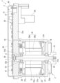
- FIG. 2 is a sectional view showing the electric power steering device 1 according to the first embodiment.
- the direction in which the central axis O of the rotating shaft 21 of the motor 2 extends may be referred to as the axial direction.
- the axial direction is also the thickness direction of the circuit board 31 in the control device 3.
- the side where the control device 3 is located is sometimes referred to as the upper side, and the side where the motor 2 is located is sometimes referred to as the lower side.
- Viewing from the axial direction is sometimes called planar view.
- plan view the direction intersecting the central axis O is sometimes referred to as the radial direction, and the direction going around the central axis O is sometimes referred to as the circumferential direction.
- the lower end of the rotating shaft 21 in the motor 2 is used as the output end 21a.
- a boss 22 connected to a driving object (for example, a steering system of a vehicle) is attached to the output end 21a.
- a speed reducer or the like may be interposed between the output end 21a and the driven object.
- the output of the motor 2 is transmitted to the driven object via the output end 21a. Note that when using the electric power steering device 1, the axial direction of the rotating shaft 21 does not need to coincide with the vertical direction.
- the motor 2 includes a motor body M and a motor case 23.
- Motor case 23 has a cylindrical portion 23a, a bottom portion 23b, and a protruding portion 23c.
- the cylindrical portion 23a extends along the axial direction.
- the bottom portion 23b is provided to close the opening at the lower end of the cylindrical portion 23a.
- the protruding portion 23c protrudes radially outward from the upper end of the cylindrical portion 23a.
- the motor main body M is housed inside a cylindrical portion 23a of the motor case 23.
- Motor case 23 is made of metal. In consideration of heat dissipation and ease of molding, the specific material for the motor case 23 is preferably an aluminum alloy, for example.
- the motor case 23 is manufactured, for example, by cutting a molded body obtained by die-casting or the like from an aluminum alloy.
- a through hole through which the rotating shaft 21 passes is formed in the center of the bottom portion 23b of the motor case 23.
- a first bearing 25 that rotatably supports the rotating shaft 21 is attached to the through hole of the bottom portion 23b.
- the motor main body M includes a rotor 26 and a stator 27.
- the rotor 26 includes a cylindrical rotor core 26a provided around the rotating shaft 21 and fixed to the rotating shaft 21, and a plurality of permanent magnets 26b provided on the outer peripheral surface of the rotor core 26a. There is.
- the plurality of permanent magnets 26b are arranged so that the polarities (S pole and N pole) on the outer circumferential surface of the rotor 26 alternate along the circumferential direction.
- the stator 27 is arranged radially outward of the rotor 26 with a gap therebetween.
- the stator 27 includes a stator core 27a made of laminated steel plates, and a winding 27b wound around the stator core 27a via an insulator 27c.
- the stator 27 is fixed within the cylindrical portion 23a of the motor case 23 by press fitting, shrink fitting, or the like.
- the rotating shaft 21, the rotor 26, and the stator 27 are arranged coaxially.
- connection ring 28 is arranged above the stator 27 and close to the winding 27b.
- the connection ring 28 has a structure in which a bus bar 29 (see FIG. 3) for electrical wiring is insert molded into an insulating resin.
- An end of each winding 27b is connected to the bus bar 29 of the connection ring 28, thereby forming a three-phase winding.
- Bus bars 29 for each phase protrude from the connection ring 28 and extend toward the control device 3 side.
- Three bus bars 29 are provided on the connection ring 28 to correspond to each phase (U, V, W). Each bus bar 29 protrudes upward from the connection ring 28 and is arranged to penetrate the circuit board 31 of the control device 3 .
- a disk-shaped heat sink 32 is fitted into the upper end of the cylindrical portion 23a of the motor case 23.
- the heat sink 32 is arranged with its central axis parallel to the axial direction.
- the height of the top surface of the heat sink 32 is equivalent to the height of the top surface of the protrusion 23c of the motor case 23.
- the upper surface of the heat sink 32 is formed into a flat shape and is flush with the upper surface of the protrusion 23c.
- the heat sink 32 is made of metal (for example, an aluminum alloy).
- the motor case 23 has a thickness greater than, for example, the thickness of the bottom portion 23b of the motor case 23 in the axial direction in order to ensure a relatively large heat capacity.
- a through hole 32a penetrating in the thickness direction is formed in the center of the heat sink 32, and a second bearing 33 (bearing) that rotatably supports the rotating shaft 21 is attached to the through hole 32a.
- the second bearing 33 supports an end 21b (upper end in this embodiment) of the rotating shaft 21 opposite to the output end 21a.
- the end portion 21 b of the rotating shaft 21 is arranged in the through hole 32 a of the heat sink 32 .
- the rotation angle sensor 7 is provided on the lower surface of the circuit board 31 and is disposed at a position facing the through hole 32a of the heat sink 32. Although the rotation angle sensor 7 protrudes downward from the lower surface of the circuit board 31, it does not interfere with the heat sink 32 because it is disposed within the through hole 32a of the heat sink 32.
- the heat sink 32 is formed with three through holes (not shown) through which the bus bars 29 of each phase (U, V, W) are passed.
- Both ends of the rotating shaft 21 are rotatably supported by a first bearing 25 and a second bearing 33. Therefore, the rotor 26 fixed to the rotating shaft 21 is also rotatable inside the stator 27 in the radial direction.
- a sensor magnet 34 is attached to the end 21b of the rotating shaft 21 on the opposite side from the output end 21a.
- the sensor magnet 34 is formed at least partially by a permanent magnet and emits a magnetic field.
- the sensor magnet 34 rotates together with the rotating shaft 21.
- the sensor magnet 34 also rotates, so the magnetic field changes.
- the sensor magnet 34 is arranged to face the rotation angle sensor 7 in the axial direction. Therefore, the rotation angle sensor 7 detects the rotation angle of the rotation shaft 21 of the motor 2 based on changes in the magnetic field generated by the sensor magnet 34 that rotates together with the rotation shaft 21.
- the control device 3 includes a circuit board 31 and an electronic circuit 35 provided on the circuit board 31.
- the circuit board 31 is, for example, a multilayer printed board in which a plurality of insulating layers and a plurality of conductor layers are laminated.
- Electronic circuit 35 includes inverter circuit 4, control circuit 5, and voltage divider circuit 6 shown in FIG.
- Electronic components such as a rotation angle sensor 7, a power semiconductor element 8, a current detection element 9, and a CPU 10 are mounted on the circuit board 31. These electronic components and the circuit pattern formed on the circuit board 31 constitute an electronic circuit 35.
- the circuit board 31 is covered from above by a cover 36.
- the cover 36 is configured to cover the circuit board 31.
- the circuit board 31 is housed in a space surrounded by the cover 36 and the motor case 23.
- the cover 36 has functions such as protecting the circuit board 31 from external electromagnetic noise and preventing electromagnetic noise generated from the circuit board 31 from leaking outside the cover 36. In order to exhibit these functions, it is desirable that the cover 36 be made of metal. In this embodiment, cover 36 is made of resin and metal.
- a connector 30 is provided on the lower surface of the protrusion 23c of the motor case 23.
- the connector 30 is used to connect the electric power steering device 1 to a vehicle-side power source 50 and a vehicle-side sensor 51.
- a plurality of connector terminals 43 are provided above the connector 30.
- Connector terminal 43 is electrically connected to a terminal (not shown) within connector 30.
- the protruding portion 23c of the motor case 23 is provided with an opening (not shown) through which the connector terminal 43 passes, and the connector terminal 43 is inserted into the inside of this opening. Further, a connector terminal 43 is inserted into a through hole formed in the circuit board 31, and the circuit pattern of the circuit board 31 and the connector terminal 43 are electrically connected by soldering.
- the method of connecting the circuit board 31 and the connector terminal 43 is not limited to soldering, and for example, press-fit may be used. Electric power from a vehicle-side power source 50 and signals from a vehicle-side sensor 51 are transmitted to the circuit board 31 via the connector 30 .
- the connector 30 is provided on the lower surface of the protrusion 23c, but the present invention is not limited to this. A hole is formed in the cover 36, and the connector is connected to the upper surface of the circuit board 31 from above through the hole. It is also possible to attach 30.
- No electronic components other than the rotation angle sensor 7 are mounted on the lower surface of the circuit board 31.
- the lower surface of the circuit board 31 is arranged in contact with the surface of the heat sink 32 on the opposite side from the motor 2 (the upper surface in this embodiment). More specifically, the lower surface of the circuit board 31 is in contact with the upper surface of the heat sink 32 via applied insulating grease (not shown in FIG. 2). It is preferable to select a grease that has high thermal conductivity.
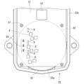
- FIG. 3 is a plan view of the circuit board 31.
- FIG. 3 shows the top surface of the circuit board 31.
- the circuit board 31 is fixed to the motor case 23 with a plurality of screws 37.
- Three bus bars 29 corresponding to each phase are connected to the circuit board 31 so as to penetrate through the circuit board 31 in the board thickness direction.
- the bus bar 29 is connected to a circuit pattern (not shown) on the circuit board 31 by soldering, and this circuit pattern is electrically connected to the winding 27b of the motor 2 via the bus bar 29.
- the circuit pattern of the circuit board 31 and the bus bars 29 of each phase may be connected not only by soldering but also by press-fitting, for example.
- a virtual area obtained by projecting the outer shape of the heat sink 32 onto the circuit board 31 is referred to as a projection area 42.
- the circuit board 31 protrudes outside the projection area 42 when viewed from the axial direction.
- the protruding portion 23c of the motor case 23 also protrudes radially outward from the cylindrical portion 23a so as to support the portion of the circuit board 31 that protrudes from the projection area 42.
- the power semiconductor element 8, the current detection element 9, etc. mounted on the circuit board 31 are heat generating elements that generate heat when a large current is passed through them as the motor 2 is driven. In order not to shorten the continuous use time of the electric power steering device 1 and to prevent a decrease in the steering assist force, it is preferable that the heat generated by these heating elements is quickly released to the outside of the electric power steering device 1. .
- the power semiconductor element 8 and the current detection element 9 are arranged on the upper surface of the circuit board 31. Further, the power semiconductor element 8 and the current detection element 9 are arranged within the projection area 42 of the circuit board 31. That is, the power semiconductor element 8 and the current detection element 9 are arranged in line with the heat sink 32 in the axial direction.
- a voltage of 12V was generally supplied to the electric power steering device from the vehicle side power supply, but in this embodiment, a voltage of 24V is supplied from the vehicle side power supply 50 to the inverter circuit 4 of the control device 3. Therefore, when the input power to the motor 2 is made equal to that of the conventional motor, the voltage is twice that of the conventional motor, so the current can be halved. Therefore, it is possible to suppress heat generation in the power semiconductor elements 8 such as FETs in the inverter circuit 4.
- the effect of suppressing the amount of heat generated is not limited to the power semiconductor elements 8 such as FETs mounted on the circuit board 31, but also to the current detection elements 9, ripple capacitors, power relays, choke coils, etc. that reduce the current. A similar effect is produced on all possible heating elements. Moreover, heat generation in the bus bar 29 and the winding 27b of the motor 2 can be similarly suppressed. Since the amount of heat generated by the power semiconductor element 8 and the current detection element 9 can be suppressed, a simplified heat dissipation structure using the heat sink 32 of this embodiment can be adopted. As described above, the power semiconductor element 8 and the current detection element 9 are arranged on the upper surface of the circuit board 31 and within the projection area 42 .
- the heat generated by the heat generating element is transferred to the heat sink through the circuit board 31 and the grease. 32 to the outside. Since the amount of heat generated by the heating element can be suppressed, the heat dissipation structure can be downsized and simplified, the weight of the electric power steering device 1 can be suppressed, and it can be manufactured at a lower cost.
- a voltage of 24V is supplied from the vehicle-side power supply 50 to the control device 3; however, the present invention is not limited to this; for example, a voltage of 48V is supplied from the vehicle-side power supply 50 to the control device 3 and the inverter circuit. 4 may be supplied.
- the input power to the motor 2 is the same as that of the conventional motor, the voltage is four times that of the conventional motor, so the current can be reduced to 1/4, and the amount of heat generated by the heating element can be further suppressed.
- the inverter circuit 4 can operate at a voltage of, for example, 42 V or more and 56 V or less. configured for proper operation. From the above, in order to suppress the amount of heat generated, the inverter circuit 4 may be configured to be driven at a voltage of 20 V or more and 56 V or less. Furthermore, although the control circuit 5 in this embodiment operates at a voltage of 12V, the withstand voltage performance of the electronic components constituting the control circuit 5 is increased so that it operates at a voltage of 24V like the inverter circuit 4. It is also possible to configure In this case, there is no need to supply the voltage of 12V to the control circuit 5 from the voltage dividing circuit 6 described above.
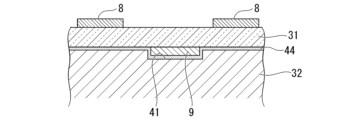
- FIG. 4 is a plan view of the circuit board 31 according to the first modification of the first embodiment.
- 5 is a sectional view taken along the line VV in FIG. 4.
- a recess 41 in which the current detection element 9 is accommodated is formed at a position facing the current detection element 9. Therefore, as in the first embodiment, the lower surface of the circuit board 31 other than the current detection element 9 can be brought close to the upper surface of the heat sink 32.
- the gap between the bottom surface of the circuit board 31 and the top surface of the heat sink 32 and the inside of the recess 41 are filled with grease 44 to form a heat radiation path.
- FIG. 6 is a plan view of the circuit board 31 according to the second modification of the first embodiment.
- 7 is a sectional view taken along the line VII-VII in FIG. 6.
- a plurality of thermal vias 45 for heat radiation are arranged around the power semiconductor element 8 on the circuit board 31 .
- the thermal via 45 is arranged on the circuit board 31 around the power semiconductor element 8 and at a different position from the power semiconductor element 8 in plan view.
- the thermal via 45 has a configuration in which the inner surface of a through hole that penetrates through the circuit board 31 in the board thickness direction is plated with a metal such as copper or gold that has good thermal conductivity.
- the heat of the power semiconductor element 8 can be more efficiently transmitted from the upper surface of the circuit board 31 to the heat sink 32 via the metal plating of the thermal via 45. It is possible to improve heat dissipation performance.
- a circuit pattern extending in the plane direction along the upper surface of the circuit board 31 may be formed to connect the thermal via 45 and the power semiconductor element 8, or a circuit pattern may be formed on the lower surface of the circuit board 31 to connect the thermal via 45 and the power semiconductor element 8.
- a circuit pattern extending in the plane direction from the thermal via 45 may be formed. By forming such a circuit pattern, the heat of the power semiconductor element 8 can be more efficiently released through the thermal via 45. Further, the thermal via 45 may be formed around a heating element other than the power semiconductor element 8.
- FIG. 8 is a plan view of the circuit board 31 according to the third modification of the first embodiment.
- FIG. 9 is a sectional view taken along the line IX-IX in FIG.
- a copper inlay 46 is arranged on the circuit board 31 at a position between the power semiconductor element 8 and the heat sink 32 in the axial direction.
- the copper inlay 46 has a configuration in which an inlay made of copper having good thermal conductivity is placed in a through hole penetrating the circuit board 31 in the board thickness direction.
- the upper surface of the copper inlay 46 is in contact with the lower surface of the power semiconductor element 8.
- the heat of the power semiconductor element 8 can be more efficiently transmitted toward the heat sink 32 via the copper inlay 46, and heat dissipation performance can be improved.
- the copper inlay 46 may be arranged between a heat generating element other than the power semiconductor element 8 and the heat sink 32.
- FIG. 10 is a block diagram showing an electric power steering device 1 according to a fourth modification of the first embodiment.
- This modification differs from the configuration of the first embodiment in that the vehicle-side power supply 50 supplies 12V power to the control device 3 of the electric power steering device 1, and the control device 3 is different from the configuration of the first embodiment described above. 1 is provided with a booster circuit 11 in place of the voltage divider circuit 6 in FIG.
- a voltage of 12V (second voltage) supplied from the vehicle-side power supply 50 is supplied to the control circuit 5 and the booster circuit 11.
- the control circuit 5 is driven by a voltage of 12V supplied from the outside.
- the booster circuit 11 generates a higher voltage of 24V (first voltage) from a voltage of 12V supplied from the outside.
- a DC/DC converter can be used as the booster circuit 11, for example.
- the 24V voltage generated by the booster circuit 11 is supplied to the inverter circuit 4, and the inverter circuit 4 is driven by the 24V voltage generated by the booster circuit 11.
- the amount of heat generated is proportional to the square of the current value, so the output voltage of the booster circuit 11 is further increased to, for example, 48V, while the current in the inverter circuit 4 is further decreased to reduce the amount of heat generated. It may be further reduced.
- the booster circuit 11 may output a voltage of 20V or more, for example.
- the inverter circuit 4 may also be configured to be driven by a voltage of 20V or more. According to this modification, measures can be taken to reduce the amount of heat generated in the electric power steering device 1 without changing the configuration of the vehicle-side power source 50 from the conventional one.
- the first voltage which is the voltage at which the inverter circuit 4 is driven
- the second voltage which is the voltage at which the control circuit 5 is driven
- the first voltage may be 20V or higher.
- the second voltage which is the voltage at which the control circuit 5 is driven
- the first voltage and the second voltage may be lower than the first voltage and at least a voltage at which the control circuit 5 can operate properly.
- the electric power steering device 1 includes the motor 2, the heat sink 32 provided with the second bearing 33 that rotatably supports the rotating shaft 21 of the motor 2, and the motor 2.
- An inverter circuit 4 for driving is provided, and a circuit board 31 is provided on the opposite side of the heat sink 32 from the motor 2.
- the power semiconductor element 8 and the current detection element 9 that constitute the inverter circuit 4 are arranged in a projection area 42 on the circuit board 31 on which the outer shape of the heat sink 32 is projected, when viewed from the axial direction of the rotation shaft 21.
- the inverter circuit 4 is configured to be driven by a first voltage of 20V or higher.
- the power semiconductor element 8 and the current detection element 9 are arranged within the projection area 42 of the circuit board 31. Therefore, even in a simplified heat dissipation structure in which the lower surface of the circuit board 31 is in contact with the upper surface of the heat sink 32 through the grease, the heat generated by the heat generating element is transferred to the heat sink through the circuit board 31 and the grease. 32 to the outside. Since the amount of heat generated by the heating element can be suppressed, the heat dissipation structure can be downsized and simplified, the weight of the electric power steering device 1 can be suppressed, and it can be manufactured at a lower cost.
- the circuit board 31 also includes a voltage divider circuit 6 (step-down circuit) that generates a second voltage lower than the first voltage from a first voltage supplied from the outside, and a voltage divider circuit 6 (step-down circuit) that generates a second voltage lower than the first voltage.
- a control circuit 5 that drives the inverter circuit 4 with the second voltage and controls the inverter circuit 4 may also be provided. According to this configuration, since the control circuit 5 is driven with the second voltage lower than the first voltage, the withstand voltage performance of the electronic components constituting the control circuit 5 is not improved. Additionally, a configuration that operates at a voltage of 12V can be adopted, and an increase in the cost of electronic components due to changes in voltage resistance can be avoided.
- the circuit board 31 is provided with a boost circuit 11 that generates the first voltage from a second voltage lower than the first voltage supplied from the outside, and the inverter circuit 4 is connected to the boost circuit 11 that generates the first voltage.
- the first voltage may be used.
- the circuit board 31 is provided with a control circuit 5 that controls the inverter circuit 4, and the control circuit 5 may be driven by a second voltage supplied from the outside.
- control circuit 5 since the control circuit 5 is driven with the second voltage lower than the first voltage, the withstand voltage performance of the electronic components constituting the control circuit 5 is not improved. Additionally, a configuration that operates at a voltage of 12V can be adopted, and an increase in the cost of electronic components due to changes in voltage resistance can be avoided.
- the heating elements constituting the inverter circuit 4 include a current detection element 9 provided on the surface of the circuit board 31 facing the heat sink 32, and a current detection element 9 is provided at a position facing the current detection element 9 of the heat sink 32.
- a recess 41 may be formed in which the number 9 is accommodated. According to this configuration, it is difficult to mount the current detection element 9 on the upper surface of the circuit board 31 due to restrictions on the mounting area, etc., and even when mounted on the lower surface of the circuit board 31, the current detection element 9 is mounted in the recess 41. By accommodating the element 9, it becomes possible to bring the surface of the circuit board 31 other than the current detection element 9 into close contact with the heat sink 32, and it is possible to maintain high heat transfer efficiency between the circuit board 31 and the heat sink 32. .
- thermal vias 45 for heat radiation may be arranged around heat generating elements such as the power semiconductor element 8 and the current detection element 9. According to this configuration, the heat generated by the heating element can be efficiently transmitted from the heating element mounting surface of the circuit board 31 to the opposite surface via the thermal via 45, thereby improving heat dissipation efficiency. can.
- a copper inlay 46 may be arranged at a position between the heat sink 32 and heat generating elements such as the power semiconductor element 8 and the current detection element 9 in the axial direction. According to this configuration, the heat generated by the heating element can be efficiently transmitted from the heating element mounting surface of the circuit board 31 to the opposite surface via the copper inlay 46, thereby improving heat dissipation efficiency. can.
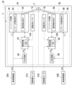
- FIG. 11 is a block diagram showing an electric power steering device 1A according to the second embodiment.
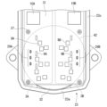
- FIG. 12 is a plan view of the circuit board 31 according to the second embodiment.
- the structure of the motor 2 in this embodiment is similar to the structure of the motor 2 according to the first embodiment. Therefore, components of the motor 2 that are the same as those in the first embodiment are given the same reference numerals, and the explanation thereof is omitted, and the explanation will focus on the different points.
- the control device 3 in this embodiment includes two control units 3A and 3B.
- the stator 27 of the motor 2 in this embodiment has two sets of three-phase windings (not shown).
- the first control unit 3A is configured to control the first three-phase winding
- the second control unit 3B is configured to control the second three-phase winding.
- the control units 3A and 3B have mutually equivalent circuit configurations. Further, each of the control units 3A and 3B has substantially the same circuit configuration as the control device 3 described in the first embodiment. Therefore, in this embodiment, among the components of the first control unit 3A, the suffix "A” is attached to the same reference numerals as the corresponding components in the first embodiment. Further, among the components of the second control unit 3B, the suffix "B" is attached to the same reference numerals as the corresponding components in the first embodiment.
- control unit 3A includes a control circuit 5A and an inverter circuit 4A.
- the configurations of control circuit 5A and inverter circuit 4A are similar to the configurations of control circuit 5 and inverter circuit 4 described in the first embodiment.
- the mounting area of the circuit board 31 in this embodiment is divided into two areas corresponding to the control units 3A and 3B, and the electronic components included in the control units 3A and 3B are also divided into two areas. They are placed in two areas.
- a plurality of power semiconductor elements 8A, a plurality of current detection elements 9A, a CPU 10A, and three bus bars 29A are arranged in the area indicated by the symbol 3A, and a plurality of power semiconductor elements 8B and a plurality of current detection elements 8B are disposed in the region indicated by the symbol 3B.
- a detection element 9B, a CPU 10B, and three bus bars 29B are arranged.
- FIG. 12 illustrations of electronic components such as ripple capacitors, choke coils, and power supply relays are omitted.
- the motor 2 is a brushless motor with three phases and two sets of windings.
- the electric power steering device 1A includes rotation angle sensors 7A and 7B for detecting the rotation angle of the motor 2.
- the rotation angle signal output by the first rotation angle sensor 7A is input to the control circuit 5A of the first control unit 3A, and the rotation angle signal output by the second rotation angle sensor 7B is input to the control circuit 5A of the first control unit 3A. It is input to circuit 5B.
- the control units 3A and 3B can each independently drive the motor 2. That is, the inverter circuits 4A and 4B each drive the motor 2. However, the control units 3A and 3B are each supplied with a current obtained by dividing the current output from the vehicle-side power source 50 into two, and the same signal output from the vehicle-side sensor 51 is input to both. For example, in the first control unit 3A, the first control circuit 5A and the first inverter circuit 4A operate based on input information from the vehicle-side sensor 51, the first rotation angle sensor 7A, and the like. As a result, the rotating shaft 21 is driven via the first winding.
- the second control circuit 5B and the second inverter circuit 4B operate based on input information from the vehicle-side sensor 51, the second rotation angle sensor 7B, and the like. Thereby, the rotating shaft 21 is driven via the second winding.
- the two control units 3A and 3B By configuring the two control units 3A and 3B to drive the motor 2 independently of each other in this way, redundancy is ensured. For example, even if a problem occurs in one of the control units 3A, 3B and the motor 2 cannot be driven, the drive of the motor 2 can be maintained by the other control unit 3A, 3B, so the steering assist force becomes completely zero. Furthermore, since the driver who is operating the steering wheel can sense the decrease in the steering assist force, the driver can quickly recognize the occurrence of the problem.
- the current supplied to each of the inverter circuits 4A and 4B is 1/2 of the current in the first embodiment, the heat generated by the heating elements of each inverter circuit 4A and 4B is lower than that in the first embodiment. can be reduced.
- FIG. 13 is a block diagram showing an electric power steering device 1B according to a modification of the second embodiment.
- the control units 3A and 3B are each supplied with a current obtained by dividing the current outputted by the vehicle-side power source 50 into two, and the same signal outputted by the vehicle-side sensor 51 is supplied to the control units 3A and 3B.
- vehicle-side power supplies 50A, 50B and vehicle-side sensors 51A, 51B which correspond to control units 3A, 3B, respectively, are used.
- the first vehicle-side power supply 50A supplies power to the first control unit 3A
- the second vehicle-side power supply 50B supplies power to the second control unit 3B.
- the first control circuit 5A and the first inverter circuit 4A operate based on input information from the first vehicle-side sensor 51A, the first rotation angle sensor 7A, etc. do.
- the second control circuit 5B and the second inverter circuit 4B operate based on input information from the second vehicle-side sensor 51B, the second rotation angle sensor 7B, etc. Operate.
- two connectors are also provided for connecting the circuit board 31 of this modification to the vehicle-side power supplies 50A, 50B and the vehicle-side sensors 51A, 51B.
- the vehicle-side power supplies 50A and 50B supply power to the control units 3A and 3B separately, but the current supplied by the vehicle-side power supplies 50A and 50B is the same as that of the vehicle-side power supply 50 shown in FIG. This is 1/2 of the supplied current. Therefore, also in this modification, the current supplied to each of the inverter circuits 4A and 4B is 1/2 of the current in the first embodiment, so that the heat generated by the heating elements of each inverter circuit 4A and 4B is reduced. , can be reduced compared to the first embodiment.
- the two inverter circuits 4A and 4B each drive the motor 2, and a two-system configuration is adopted; however, the number of inverter circuits is not limited to two, and the number of inverter circuits provided is not limited to two.
- the number of circuits may be three or more, and each circuit may be configured to drive the motor 2.
- a four-system configuration may be adopted.
- the present disclosure is not limited to the configurations of the embodiments and modifications described above, but is limited only by the scope of the claims. It is possible to combine the modified examples described in each embodiment with each other, or to modify or omit the configuration according to each embodiment as appropriate.
- the second embodiment is explained based on the control device 3 shown in FIG. 1 of the first embodiment, the modifications 1 to 4 of the first embodiment are different from the second embodiment. It is also possible to apply the control device 3 described.
Abstract
This electric power steering device (1, 1A, 1B) comprises: a motor (2); a heatsink (32) provided with a bearing (33) that rotatably supports a rotary shaft (21) of the motor; and a circuit substrate (31) which is provided with an inverter circuit (4, 4A, 4B) for driving the motor and which is disposed on a surface of the heatsink on the side opposite to the motor. Heater elements (8, 8A, 8B, 9, 9A, 9B) constituting the inverter circuit are arranged within a projection domain (42) which is formed on the circuit substrate and onto which the outer shape of the heatsink is projected, as viewed from the axial direction of the rotary shaft. The inverter circuit is configured to be driven at a first voltage of 20 V or higher.
Description
本開示は、電動パワーステアリング装置に関する。
The present disclosure relates to an electric power steering device.
特許文献1には、車両に取り付けられ、運転者の操舵動作を補助する電動パワーステアリング装置が開示されている。電動パワーステアリング装置は、モータを駆動するインバータ回路と、インバータ回路を制御する制御回路と、を回路基板上に設けた構成の制御装置を備え、この制御装置はモータと一体化されている。インバータ回路にはスイッチング素子等のパワー半導体素子が含まれ、このパワー半導体素子は、モータの駆動に伴い発熱する発熱素子である。また、回路基板に実装された電子部品には使用温度の上限が定められている場合があり、この上限に達した場合、電子部品の誤作動や破損を防止するために、電動パワーステアリング装置の動作を休止する等の対策を採る場合がある。この場合、電動パワーステアリング装置の継続使用時間が短くなり、操舵補助力の低下に繋がる可能性があることから、発熱素子の熱を逃がす放熱構造が電動パワーステアリング装置に設けられている。
Patent Document 1 discloses an electric power steering device that is attached to a vehicle and assists a driver's steering operation. An electric power steering device includes a control device configured to have an inverter circuit that drives a motor and a control circuit that controls the inverter circuit provided on a circuit board, and this control device is integrated with the motor. The inverter circuit includes power semiconductor elements such as switching elements, and the power semiconductor elements are heating elements that generate heat as the motor is driven. Additionally, electronic components mounted on circuit boards may have an upper limit for their operating temperature, and when this upper limit is reached, the electric power steering system must be operated to prevent malfunction or damage to the electronic components. Measures such as suspending operations may be taken. In this case, the continuous use time of the electric power steering device may be shortened, leading to a decrease in steering assist force, so the electric power steering device is provided with a heat dissipation structure for dissipating the heat of the heating element.
特許文献1は、放熱構造として、一方の面に発熱素子を実装した回路基板の他方の面と、モータの筐体の一部を構成するヒートシンクと、の間に放熱材を設け、回路基板を筐体にねじ固定することで、放熱材を回路基板とヒートシンクとに密着させて、回路基板の発熱素子が発生した熱を、放熱材を介してヒートシンクに放熱する構造を採用している。このような構造は発熱素子の熱を効率よく放熱するためのものであるが、回路基板およびヒートシンクには放熱材と密着させるための面積を確保する必要があり、放熱材を利用することにより装置が大型化したり、製品重量が増加したりするといった課題があった。
Patent Document 1 discloses a heat dissipation structure in which a heat dissipation material is provided between the other surface of a circuit board on which a heat generating element is mounted on one surface and a heat sink that constitutes a part of a motor casing, and the circuit board is By fixing screws to the housing, the heat dissipation material is brought into close contact with the circuit board and heat sink, and the heat generated by the heat generating elements of the circuit board is radiated to the heat sink via the heat dissipation material. This type of structure is designed to efficiently dissipate heat from the heating element, but it is necessary to secure an area for the circuit board and heat sink to be in close contact with the heat dissipation material, and by using the heat dissipation material, the device There were issues such as the size of the product becoming larger and the weight of the product increasing.
本開示は、上記のような課題を解決するためになされたもので、発熱素子の発熱量を抑えることで放熱構造を小型化および簡素化し、製品重量を抑え、低コストでの製造を可能とする制御装置一体型の電動パワーステアリング装置を提供することを目的とする。
The present disclosure was made in order to solve the above-mentioned problems, and by suppressing the heat generation amount of the heating element, the heat dissipation structure can be made smaller and simpler, the product weight can be reduced, and manufacturing can be made at low cost. The purpose of the present invention is to provide an electric power steering device with an integrated control device.
本開示に係る電動パワーステアリング装置は、モータと、前記モータの回転軸を回転可能に支持する軸受が設けられたヒートシンクと、前記モータを駆動するインバータ回路が設けられるとともに、前記ヒートシンクの前記モータと逆側の面に配置された回路基板と、を備え、前記インバータ回路を構成する発熱素子が、前記回転軸の軸方向から見て、前記ヒートシンクの外形を投影した前記回路基板における投影領域内に配置され、前記インバータ回路は、20V以上の第1の電圧によって駆動するように構成されている。
An electric power steering device according to the present disclosure includes a motor, a heat sink provided with a bearing that rotatably supports a rotating shaft of the motor, and an inverter circuit that drives the motor. a circuit board disposed on the opposite surface, and the heating element constituting the inverter circuit is located within a projection area of the circuit board on which the outer shape of the heat sink is projected, when viewed from the axial direction of the rotation shaft. The inverter circuit is configured to be driven by a first voltage of 20V or more.
本開示によれば、発熱素子の発熱量が抑制できるため、放熱構造を小型化および簡素化でき、製品重量が抑えられ、低コストでの製造が可能となる制御装置一体型の電動パワーステアリング装置を提供できる。
According to the present disclosure, since the heat generation amount of the heating element can be suppressed, the heat dissipation structure can be downsized and simplified, the product weight can be suppressed, and the electric power steering device integrated with the control device can be manufactured at low cost. can be provided.
実施の形態1.
図1は、実施の形態1に係る電動パワーステアリング装置1を示すブロック図である。図1に示す電動パワーステアリング装置1は、操舵補助力を発生するモータ2と、モータ2を制御する制御装置3と、を備えている。本実施の形態におけるモータ2は、3相ブラシレスモータである。制御装置3には、車両に搭載されている、車両側電源50および車両側センサ51が電気的に接続されている。すなわち、車両側電源50および車両側センサ51は、電動パワーステアリング装置1の外部に設けられている。車両側電源50は、例えばバッテリであり、制御装置3に対して24V(第1の電圧)の直流電力を供給する。車両側センサ51の具体例としては、車両の速度を検出する車速センサ、ハンドルの操舵トルクを検出するトルクセンサ等が挙げられる。 Embodiment 1.
FIG. 1 is a block diagram showing an electric power steering device 1 according to the first embodiment. An electric power steering device 1 shown in FIG. 1 includes amotor 2 that generates a steering assist force, and a control device 3 that controls the motor 2. Motor 2 in this embodiment is a three-phase brushless motor. The control device 3 is electrically connected to a vehicle-side power source 50 and a vehicle-side sensor 51 mounted on the vehicle. That is, the vehicle-side power supply 50 and the vehicle-side sensor 51 are provided outside the electric power steering device 1. The vehicle-side power source 50 is, for example, a battery, and supplies 24V (first voltage) DC power to the control device 3. Specific examples of the vehicle-side sensor 51 include a vehicle speed sensor that detects the speed of the vehicle, a torque sensor that detects the steering torque of a steering wheel, and the like.
図1は、実施の形態1に係る電動パワーステアリング装置1を示すブロック図である。図1に示す電動パワーステアリング装置1は、操舵補助力を発生するモータ2と、モータ2を制御する制御装置3と、を備えている。本実施の形態におけるモータ2は、3相ブラシレスモータである。制御装置3には、車両に搭載されている、車両側電源50および車両側センサ51が電気的に接続されている。すなわち、車両側電源50および車両側センサ51は、電動パワーステアリング装置1の外部に設けられている。車両側電源50は、例えばバッテリであり、制御装置3に対して24V(第1の電圧)の直流電力を供給する。車両側センサ51の具体例としては、車両の速度を検出する車速センサ、ハンドルの操舵トルクを検出するトルクセンサ等が挙げられる。 Embodiment 1.
FIG. 1 is a block diagram showing an electric power steering device 1 according to the first embodiment. An electric power steering device 1 shown in FIG. 1 includes a
図1に示すように、制御装置3は、インバータ回路4と、制御回路5と、分圧回路6(降圧回路)と、回転角センサ7と、を備えている。
インバータ回路4は、制御回路5によって制御され、モータ2へ電流を供給および遮断するように構成されている。本実施の形態におけるインバータ回路4は、車両側電源50から24Vの電力が供給され、この電力によって駆動するように構成されている。ただし、車両側電源50の放電および充電状況から、車両側電源50から供給される電圧は必ずしも一定ではなく、インバータ回路4は例えば20V以上32V以下の電圧であれば適切に動作するように構成されている。インバータ回路4は、スイッチング素子として機能する複数のパワー半導体素子8と、電流の大きさを検出する電流検出素子9と、を有している。また、図示しないが、インバータ回路4は、モータ2に流れる電流のリップルを吸収する複数のリップルコンデンサを有している。パワー半導体素子8の例として、FET(Field Effect Transistor:電界効果トランジスタ)を採用可能である。複数のスイッチング素子によって複数のブリッジ回路が構成され、各ブリッジ回路は、モータ2が有する3相(U、V、W)の巻線それぞれに電流を供給するように構成されている。電流検出素子9は、例えばシャント抵抗であってもよい。 As shown in FIG. 1, thecontrol device 3 includes an inverter circuit 4, a control circuit 5, a voltage dividing circuit 6 (step-down circuit), and a rotation angle sensor 7.
Theinverter circuit 4 is controlled by the control circuit 5 and is configured to supply and cut off current to the motor 2. The inverter circuit 4 in this embodiment is configured to be supplied with 24V power from the vehicle-side power source 50 and driven by this power. However, due to the discharging and charging conditions of the vehicle-side power source 50, the voltage supplied from the vehicle-side power source 50 is not necessarily constant, and the inverter circuit 4 is configured to operate appropriately at a voltage of, for example, 20 V or more and 32 V or less. ing. The inverter circuit 4 includes a plurality of power semiconductor elements 8 that function as switching elements and a current detection element 9 that detects the magnitude of current. Although not shown, the inverter circuit 4 includes a plurality of ripple capacitors that absorb ripples in the current flowing through the motor 2. As an example of the power semiconductor element 8, an FET (Field Effect Transistor) can be used. A plurality of bridge circuits are configured by a plurality of switching elements, and each bridge circuit is configured to supply current to each of the three-phase (U, V, W) windings of the motor 2. The current detection element 9 may be, for example, a shunt resistor.
インバータ回路4は、制御回路5によって制御され、モータ2へ電流を供給および遮断するように構成されている。本実施の形態におけるインバータ回路4は、車両側電源50から24Vの電力が供給され、この電力によって駆動するように構成されている。ただし、車両側電源50の放電および充電状況から、車両側電源50から供給される電圧は必ずしも一定ではなく、インバータ回路4は例えば20V以上32V以下の電圧であれば適切に動作するように構成されている。インバータ回路4は、スイッチング素子として機能する複数のパワー半導体素子8と、電流の大きさを検出する電流検出素子9と、を有している。また、図示しないが、インバータ回路4は、モータ2に流れる電流のリップルを吸収する複数のリップルコンデンサを有している。パワー半導体素子8の例として、FET(Field Effect Transistor:電界効果トランジスタ)を採用可能である。複数のスイッチング素子によって複数のブリッジ回路が構成され、各ブリッジ回路は、モータ2が有する3相(U、V、W)の巻線それぞれに電流を供給するように構成されている。電流検出素子9は、例えばシャント抵抗であってもよい。 As shown in FIG. 1, the
The
制御回路5は、演算処理を行うCPU10を有している。また、図示しないが、制御回路5は、CPU10がインバータ回路4をスイッチング制御するために用いられる駆動回路、回転角センサ7および車両側センサ51からの信号をCPU10に伝える入力回路、電圧を調整するレギュレータ回路等を有してもよい。CPU10、駆動回路、入力回路、レギュレータ回路の各機能は、例えばIC(Integrated Circuit)あるいはASIC(Application Specific Integrated Circuit)等によって実現することができる。CPU10は各種の入力信号を取得するように構成されており、入力信号の具体例としては、車両側センサ51からの情報、インバータ回路4内の各部の電圧、電流検出素子9によって検出されたモータ2の駆動電流の大きさ、および回転角センサ7による回転角の検出結果、などが挙げられる。
The control circuit 5 has a CPU 10 that performs arithmetic processing. Although not shown, the control circuit 5 includes a drive circuit used by the CPU 10 to control switching of the inverter circuit 4, an input circuit that transmits signals from the rotation angle sensor 7 and the vehicle-side sensor 51 to the CPU 10, and adjusts voltage. It may also include a regulator circuit or the like. Each function of the CPU 10, drive circuit, input circuit, and regulator circuit can be realized by, for example, an IC (Integrated Circuit) or an ASIC (Application Specific Integrated Circuit). The CPU 10 is configured to obtain various input signals, and specific examples of the input signals include information from the vehicle-side sensor 51, voltages of various parts in the inverter circuit 4, and motor detected by the current detection element 9. 2, the magnitude of the drive current, the detection result of the rotation angle by the rotation angle sensor 7, etc.
分圧回路6は、車両側電源50から供給される24Vの電圧からそれよりも低い12Vの電圧(第2の電圧)を生成する回路(降圧回路)である。分圧回路6は、例えば2つの抵抗器から構成される。分圧回路6は制御回路5に電気的に接続されており、生成した12Vの電圧を制御回路5に供給する。
なお、分圧回路6に代えて、車両側電源50から供給される24Vの電圧(第1の電圧)からそれよりも低い電圧(第2の電圧)を生成するために、例えばレギュレータや降圧型のDC/DCコンバータが設けられてもよい。 Thevoltage divider circuit 6 is a circuit (step-down circuit) that generates a lower voltage of 12V (second voltage) from a voltage of 24V supplied from the vehicle-side power supply 50. The voltage dividing circuit 6 is composed of, for example, two resistors. The voltage dividing circuit 6 is electrically connected to the control circuit 5 and supplies the generated 12V voltage to the control circuit 5.
In addition, instead of thevoltage divider circuit 6, in order to generate a lower voltage (second voltage) from the 24V voltage (first voltage) supplied from the vehicle side power supply 50, for example, a regulator or a step-down type A DC/DC converter may be provided.
なお、分圧回路6に代えて、車両側電源50から供給される24Vの電圧(第1の電圧)からそれよりも低い電圧(第2の電圧)を生成するために、例えばレギュレータや降圧型のDC/DCコンバータが設けられてもよい。 The
In addition, instead of the
回転角センサ7は、モータ2の回転角を検出するために用いられる。本実施の形態における回転角センサ7は、磁気の変化によってモータ2の回転角を検出する。回転角センサ7には、分圧回路6または前記レギュレータ回路によって適切な電圧に調整された電力が供給される。
The rotation angle sensor 7 is used to detect the rotation angle of the motor 2. The rotation angle sensor 7 in this embodiment detects the rotation angle of the motor 2 based on changes in magnetism. The rotation angle sensor 7 is supplied with power adjusted to an appropriate voltage by the voltage dividing circuit 6 or the regulator circuit.
また、図示しないが、制御装置3は、インバータ回路4への電力供給を遮断可能な電源リレーと、車両側電源50に接続されたノイズフィルタと、を有してもよい。電源リレーは、車両側電源50の制御装置3に対する誤った接続などからインバータ回路4を保護するために用いられる。電源リレーに対しても、スイッチング素子であるFETを用いることができる。ノイズフィルタを設けた場合、車両側電源50から供給された電力は、当該ノイズフィルタを通過してからインバータ回路4および分圧回路6に供給される。ノイズフィルタは、積層セラミックコンデンサ、およびチョークコイルから構成されてもよい。
Although not shown, the control device 3 may include a power relay that can cut off power supply to the inverter circuit 4 and a noise filter connected to the vehicle-side power source 50. The power supply relay is used to protect the inverter circuit 4 from erroneous connection of the vehicle-side power supply 50 to the control device 3. An FET, which is a switching element, can also be used for the power relay. When a noise filter is provided, the power supplied from the vehicle-side power supply 50 is supplied to the inverter circuit 4 and the voltage dividing circuit 6 after passing through the noise filter. The noise filter may include a multilayer ceramic capacitor and a choke coil.
制御回路5の概略の動作を説明する。CPU10は、取得した入力信号に基づいて、モータ2の各巻線へ供給する駆動電流の大きさ等を演算する。演算結果に基づき、CPU10はインバータ回路4をスイッチング制御する。より具体的には、CPU10は、前記駆動回路に制御指示を行う。駆動回路は、CPU10からの制御指示に基づき、スイッチング素子として機能するパワー半導体素子8を制御する。駆動回路を介したCPU10の制御は、モータ2の相(U、V、W)ごとに行われる。すなわち、各相(U、V、W)のパワー半導体素子8が、駆動回路により駆動されることで、所定の電流がモータ2の各巻線へ流れる。
The general operation of the control circuit 5 will be explained. The CPU 10 calculates the magnitude of the drive current to be supplied to each winding of the motor 2 based on the acquired input signal. Based on the calculation result, the CPU 10 controls switching of the inverter circuit 4. More specifically, the CPU 10 issues control instructions to the drive circuit. The drive circuit controls the power semiconductor element 8, which functions as a switching element, based on control instructions from the CPU 10. Control of the CPU 10 via the drive circuit is performed for each phase (U, V, W) of the motor 2. That is, the power semiconductor elements 8 of each phase (U, V, W) are driven by the drive circuit, so that a predetermined current flows to each winding of the motor 2.
モータ2の各巻線に供給された電流値の大きさは、電流検出素子9を介して、実電流値としてCPU10に提供される。CPU10は、演算値(目標値)と実電流値との偏差に応じてフィードバック制御を実行する。
また、CPU10は、回転角センサ7によって得られた回転角情報を、モータ2の回転制御に利用している。具体的に、CPU10は、回転角センサ7によって得られた回転角情報を用いて、モータ2の回転軸21の回転角(位相)または回転速度を算出する。 The magnitude of the current value supplied to each winding of themotor 2 is provided to the CPU 10 as an actual current value via the current detection element 9. The CPU 10 executes feedback control according to the deviation between the calculated value (target value) and the actual current value.
Further, theCPU 10 uses the rotation angle information obtained by the rotation angle sensor 7 to control the rotation of the motor 2. Specifically, the CPU 10 uses the rotation angle information obtained by the rotation angle sensor 7 to calculate the rotation angle (phase) or rotation speed of the rotation shaft 21 of the motor 2.
また、CPU10は、回転角センサ7によって得られた回転角情報を、モータ2の回転制御に利用している。具体的に、CPU10は、回転角センサ7によって得られた回転角情報を用いて、モータ2の回転軸21の回転角(位相)または回転速度を算出する。 The magnitude of the current value supplied to each winding of the
Further, the
次に、制御装置3およびモータ2を備えた、電動パワーステアリング装置1の各部の構造を、図2に基づいて説明する。
図2は実施の形態1に係る電動パワーステアリング装置1を示す断面図である。以下の説明では、モータ2における回転軸21の中心軸線Oが延びる方向を軸方向という場合がある。軸方向は、制御装置3における回路基板31の厚さ方向でもある。また、軸方向において、制御装置3が位置する側を上方といい、モータ2が位置する側を下方という場合がある。軸方向から見ることを平面視という場合がある。平面視において、中心軸線Oに交差する方向を径方向といい、中心軸線O回りに周回する方向を周方向という場合がある。 Next, the structure of each part of the electric power steering device 1, which includes thecontrol device 3 and the motor 2, will be explained based on FIG. 2.
FIG. 2 is a sectional view showing the electric power steering device 1 according to the first embodiment. In the following description, the direction in which the central axis O of therotating shaft 21 of the motor 2 extends may be referred to as the axial direction. The axial direction is also the thickness direction of the circuit board 31 in the control device 3. Further, in the axial direction, the side where the control device 3 is located is sometimes referred to as the upper side, and the side where the motor 2 is located is sometimes referred to as the lower side. Viewing from the axial direction is sometimes called planar view. In plan view, the direction intersecting the central axis O is sometimes referred to as the radial direction, and the direction going around the central axis O is sometimes referred to as the circumferential direction.
図2は実施の形態1に係る電動パワーステアリング装置1を示す断面図である。以下の説明では、モータ2における回転軸21の中心軸線Oが延びる方向を軸方向という場合がある。軸方向は、制御装置3における回路基板31の厚さ方向でもある。また、軸方向において、制御装置3が位置する側を上方といい、モータ2が位置する側を下方という場合がある。軸方向から見ることを平面視という場合がある。平面視において、中心軸線Oに交差する方向を径方向といい、中心軸線O回りに周回する方向を周方向という場合がある。 Next, the structure of each part of the electric power steering device 1, which includes the
FIG. 2 is a sectional view showing the electric power steering device 1 according to the first embodiment. In the following description, the direction in which the central axis O of the
モータ2における回転軸21の下端部は出力端21aとして用いられる。出力端21aには、駆動対象(例えば車両の操舵系)に接続されるボス22が取り付けられている。出力端21aと駆動対象との間に、減速機などが介在してもよい。モータ2の出力は、出力端21aを介して駆動対象に伝達される。なお、電動パワーステアリング装置1を使用する際に、回転軸21の軸方向が鉛直方向と一致していなくてもよい。
The lower end of the rotating shaft 21 in the motor 2 is used as the output end 21a. A boss 22 connected to a driving object (for example, a steering system of a vehicle) is attached to the output end 21a. A speed reducer or the like may be interposed between the output end 21a and the driven object. The output of the motor 2 is transmitted to the driven object via the output end 21a. Note that when using the electric power steering device 1, the axial direction of the rotating shaft 21 does not need to coincide with the vertical direction.
モータ2は、モータ本体Mおよびモータケース23を備える。モータケース23は、円筒部23aと、底部23bと、突出部23cと、を有している。円筒部23aは軸方向に沿って延びている。底部23bは、円筒部23aの下端の開口を塞ぐように設けられている。突出部23cは、円筒部23aの上端部から、径方向外側に向けて突出している。モータ本体Mは、モータケース23における円筒部23aの内部に収容されている。モータケース23は金属製である。放熱性および成形しやすさを考慮すると、モータケース23の具体的な材質としては、例えばアルミニウム系合金が好適である。モータケース23は、例えば、アルミニウム系合金からダイカスト等によって得られた成型体に対して、切削加工を行うことで作製される。モータケース23の底部23bの中央には、回転軸21を通す貫通穴が形成されている。底部23bの貫通穴には、回転軸21を回転可能に支持する第1軸受25が取り付けられている。
The motor 2 includes a motor body M and a motor case 23. Motor case 23 has a cylindrical portion 23a, a bottom portion 23b, and a protruding portion 23c. The cylindrical portion 23a extends along the axial direction. The bottom portion 23b is provided to close the opening at the lower end of the cylindrical portion 23a. The protruding portion 23c protrudes radially outward from the upper end of the cylindrical portion 23a. The motor main body M is housed inside a cylindrical portion 23a of the motor case 23. Motor case 23 is made of metal. In consideration of heat dissipation and ease of molding, the specific material for the motor case 23 is preferably an aluminum alloy, for example. The motor case 23 is manufactured, for example, by cutting a molded body obtained by die-casting or the like from an aluminum alloy. A through hole through which the rotating shaft 21 passes is formed in the center of the bottom portion 23b of the motor case 23. A first bearing 25 that rotatably supports the rotating shaft 21 is attached to the through hole of the bottom portion 23b.
モータ本体Mは、ロータ26およびステータ27を備えている。ロータ26は、回転軸21の周囲に設けられるとともに回転軸21に固着された円筒状の回転子鉄心26aと、回転子鉄心26aの外周面に設けられた複数の永久磁石26bと、を備えている。複数の永久磁石26bは、ロータ26の外周面における極性(S極およびN極)が、周方向に沿って交互に入れ替わるように配置されている。ステータ27は、ロータ26の径方向外側に、隙間に空けて配置されている。ステータ27は、鋼板を積層してなる固定子鉄心27aと、固定子鉄心27aにインシュレータ27cを介して巻回された巻線27bと、を有している。ステータ27は、モータケース23の円筒部23a内に圧入または焼き嵌め等によって固定されている。回転軸21、ロータ26、およびステータ27は、同軸上に配置されている。
The motor main body M includes a rotor 26 and a stator 27. The rotor 26 includes a cylindrical rotor core 26a provided around the rotating shaft 21 and fixed to the rotating shaft 21, and a plurality of permanent magnets 26b provided on the outer peripheral surface of the rotor core 26a. There is. The plurality of permanent magnets 26b are arranged so that the polarities (S pole and N pole) on the outer circumferential surface of the rotor 26 alternate along the circumferential direction. The stator 27 is arranged radially outward of the rotor 26 with a gap therebetween. The stator 27 includes a stator core 27a made of laminated steel plates, and a winding 27b wound around the stator core 27a via an insulator 27c. The stator 27 is fixed within the cylindrical portion 23a of the motor case 23 by press fitting, shrink fitting, or the like. The rotating shaft 21, the rotor 26, and the stator 27 are arranged coaxially.
ステータ27の上方には、巻線27bに近接して、環状の接続リング28が配置されている。接続リング28は、電気配線用のバスバー29(図3参照)が絶縁性樹脂にインサート成形された構造を有する。各巻線27bの端部が接続リング28のバスバー29に接続されることで、3相巻線を構成している。接続リング28から突き出された各相のバスバー29が、制御装置3側に延びている。各相(U、V、W)に対応させて、接続リング28には3本のバスバー29が設けられている。各バスバー29は接続リング28から上方に突出し、制御装置3の回路基板31を貫通するように配置されている。
An annular connecting ring 28 is arranged above the stator 27 and close to the winding 27b. The connection ring 28 has a structure in which a bus bar 29 (see FIG. 3) for electrical wiring is insert molded into an insulating resin. An end of each winding 27b is connected to the bus bar 29 of the connection ring 28, thereby forming a three-phase winding. Bus bars 29 for each phase protrude from the connection ring 28 and extend toward the control device 3 side. Three bus bars 29 are provided on the connection ring 28 to correspond to each phase (U, V, W). Each bus bar 29 protrudes upward from the connection ring 28 and is arranged to penetrate the circuit board 31 of the control device 3 .
モータケース23の円筒部23aにおける上端部内には、円板状のヒートシンク32が嵌合されている。ヒートシンク32は、その中心軸が軸方向に平行となる姿勢で配置されている。ヒートシンク32の上面の高さは、モータケース23の突出部23cの上面の高さと同等となっている。本実施の形態において、ヒートシンク32の上面は平面状に形成され、突出部23cの上面と面一である。ヒートシンク32は、金属(例えばアルミニウム系合金)によって形成されている。モータケース23は、比較的大きな熱容量を確保すべく、例えばモータケース23の底部23bの軸方向における板厚よりも大きな板厚を有している。
A disk-shaped heat sink 32 is fitted into the upper end of the cylindrical portion 23a of the motor case 23. The heat sink 32 is arranged with its central axis parallel to the axial direction. The height of the top surface of the heat sink 32 is equivalent to the height of the top surface of the protrusion 23c of the motor case 23. In this embodiment, the upper surface of the heat sink 32 is formed into a flat shape and is flush with the upper surface of the protrusion 23c. The heat sink 32 is made of metal (for example, an aluminum alloy). The motor case 23 has a thickness greater than, for example, the thickness of the bottom portion 23b of the motor case 23 in the axial direction in order to ensure a relatively large heat capacity.
ヒートシンク32の中央部には、板厚方向に貫通する貫通穴32aが形成され、この貫通穴32aに、回転軸21を回転可能に支持する第2軸受33(軸受)が取り付けられている。第2軸受33は、回転軸21の出力端21aと反対側の端部21b(本実施の形態における上端)を支持している。ヒートシンク32の貫通穴32aには、回転軸21の端部21bが配置されている。回転角センサ7は回路基板31の下面に設けられ、ヒートシンク32の貫通穴32aに対向する位置に配置されている。回転角センサ7は回路基板31の下面から下方に突出しているが、ヒートシンク32の貫通穴32a内に配置されているため、ヒートシンク32には干渉していない。さらに、ヒートシンク32には、各相(U、V、W)のバスバー29を通す3つの貫通穴(不図示)が形成されている。
A through hole 32a penetrating in the thickness direction is formed in the center of the heat sink 32, and a second bearing 33 (bearing) that rotatably supports the rotating shaft 21 is attached to the through hole 32a. The second bearing 33 supports an end 21b (upper end in this embodiment) of the rotating shaft 21 opposite to the output end 21a. The end portion 21 b of the rotating shaft 21 is arranged in the through hole 32 a of the heat sink 32 . The rotation angle sensor 7 is provided on the lower surface of the circuit board 31 and is disposed at a position facing the through hole 32a of the heat sink 32. Although the rotation angle sensor 7 protrudes downward from the lower surface of the circuit board 31, it does not interfere with the heat sink 32 because it is disposed within the through hole 32a of the heat sink 32. Further, the heat sink 32 is formed with three through holes (not shown) through which the bus bars 29 of each phase (U, V, W) are passed.
回転軸21の両端部は、第1軸受25および第2軸受33によって回転可能に支持されている。このため、回転軸21に固着したロータ26も、ステータ27の径方向内側において回転可能となっている。出力端21aとは反対側の回転軸21の端部21bには、センサマグネット34が取り付けられている。センサマグネット34は、少なくとも一部が永久磁石により形成され、磁界を発する。センサマグネット34は、回転軸21とともに回転する。回転軸21が回転することに伴い、センサマグネット34も回転するため、磁界が変化する。センサマグネット34は、軸方向で回転角センサ7に対向するように配置されている。このため、回転角センサ7は、回転軸21とともに回転するセンサマグネット34が発する磁界の変化により、モータ2の回転軸21の回転角を検出する。
Both ends of the rotating shaft 21 are rotatably supported by a first bearing 25 and a second bearing 33. Therefore, the rotor 26 fixed to the rotating shaft 21 is also rotatable inside the stator 27 in the radial direction. A sensor magnet 34 is attached to the end 21b of the rotating shaft 21 on the opposite side from the output end 21a. The sensor magnet 34 is formed at least partially by a permanent magnet and emits a magnetic field. The sensor magnet 34 rotates together with the rotating shaft 21. As the rotating shaft 21 rotates, the sensor magnet 34 also rotates, so the magnetic field changes. The sensor magnet 34 is arranged to face the rotation angle sensor 7 in the axial direction. Therefore, the rotation angle sensor 7 detects the rotation angle of the rotation shaft 21 of the motor 2 based on changes in the magnetic field generated by the sensor magnet 34 that rotates together with the rotation shaft 21.
制御装置3は、回路基板31と、回路基板31上に設けられた電子回路35と、を備える。回路基板31は、例えば、複数の絶縁層および複数の導体層が積層された多層プリント基板である。電子回路35には、図1に示すインバータ回路4、制御回路5、および分圧回路6が含まれる。回路基板31には、回転角センサ7、パワー半導体素子8、電流検出素子9、CPU10等の電子部品が実装される。これらの電子部品および回路基板31に形成された回路パターンにより、電子回路35が構成されている。回路基板31は上方からカバー36によって覆われている。
The control device 3 includes a circuit board 31 and an electronic circuit 35 provided on the circuit board 31. The circuit board 31 is, for example, a multilayer printed board in which a plurality of insulating layers and a plurality of conductor layers are laminated. Electronic circuit 35 includes inverter circuit 4, control circuit 5, and voltage divider circuit 6 shown in FIG. Electronic components such as a rotation angle sensor 7, a power semiconductor element 8, a current detection element 9, and a CPU 10 are mounted on the circuit board 31. These electronic components and the circuit pattern formed on the circuit board 31 constitute an electronic circuit 35. The circuit board 31 is covered from above by a cover 36.
カバー36は、回路基板31を覆うように構成されている。回路基板31は、カバー36およびモータケース23によって囲まれた空間に収納されている。カバー36は、外来する電磁ノイズから回路基板31を保護する機能や、回路基板31から発生する電磁ノイズがカバー36の外に漏れ出すのを防ぐ機能などを有する。これらの機能を発揮するため、カバー36は金属を用いて作製されることが望ましい。本実施の形態において、カバー36は樹脂および金属で作製されている。
The cover 36 is configured to cover the circuit board 31. The circuit board 31 is housed in a space surrounded by the cover 36 and the motor case 23. The cover 36 has functions such as protecting the circuit board 31 from external electromagnetic noise and preventing electromagnetic noise generated from the circuit board 31 from leaking outside the cover 36. In order to exhibit these functions, it is desirable that the cover 36 be made of metal. In this embodiment, cover 36 is made of resin and metal.
モータケース23の突出部23cの下面には、コネクタ30が設けられている。コネクタ30は、電動パワーステアリング装置1を、車両側電源50および車両側センサ51と接続するために用いられる。コネクタ30の上方には複数のコネクタターミナル43が設けられている。コネクタターミナル43は、コネクタ30内の端子(不図示)と電気的に接続されている。モータケース23の突出部23cには、コネクタターミナル43を通すための開口(不図示)が設けられており、この開口の内側にコネクタターミナル43が挿通されている。また、回路基板31に形成された貫通穴にコネクタターミナル43が挿入され、はんだ付けによって回路基板31の回路パターンとコネクタターミナル43とが電気的に接続されている。なお、回路基板31とコネクタターミナル43との接続方法は、はんだ付けに限らず、例えばプレスフィットを採用してもよい。コネクタ30を介して、車両側電源50の電力と車両側センサ51の信号が回路基板31に伝達される。なお、本実施の形態においてコネクタ30は突出部23cの下面に設けられているが、これに限定されず、カバー36に穴を形成し、その穴を介して上方から回路基板31の上面にコネクタ30を取り付けることも可能である。
A connector 30 is provided on the lower surface of the protrusion 23c of the motor case 23. The connector 30 is used to connect the electric power steering device 1 to a vehicle-side power source 50 and a vehicle-side sensor 51. A plurality of connector terminals 43 are provided above the connector 30. Connector terminal 43 is electrically connected to a terminal (not shown) within connector 30. The protruding portion 23c of the motor case 23 is provided with an opening (not shown) through which the connector terminal 43 passes, and the connector terminal 43 is inserted into the inside of this opening. Further, a connector terminal 43 is inserted into a through hole formed in the circuit board 31, and the circuit pattern of the circuit board 31 and the connector terminal 43 are electrically connected by soldering. Note that the method of connecting the circuit board 31 and the connector terminal 43 is not limited to soldering, and for example, press-fit may be used. Electric power from a vehicle-side power source 50 and signals from a vehicle-side sensor 51 are transmitted to the circuit board 31 via the connector 30 . In this embodiment, the connector 30 is provided on the lower surface of the protrusion 23c, but the present invention is not limited to this. A hole is formed in the cover 36, and the connector is connected to the upper surface of the circuit board 31 from above through the hole. It is also possible to attach 30.
回路基板31の下面に回転角センサ7以外の電子部品は実装されていない。回路基板31の下面は、ヒートシンク32のモータ2と逆側の面(本実施の形態における上面)に接して配置されている。より具体的には、回路基板31の下面は、塗布された絶縁性のグリス(図2では不図示)を介してヒートシンク32の上面に接している。グリスは、高い熱伝導性を有するものを選択することが好ましい。
No electronic components other than the rotation angle sensor 7 are mounted on the lower surface of the circuit board 31. The lower surface of the circuit board 31 is arranged in contact with the surface of the heat sink 32 on the opposite side from the motor 2 (the upper surface in this embodiment). More specifically, the lower surface of the circuit board 31 is in contact with the upper surface of the heat sink 32 via applied insulating grease (not shown in FIG. 2). It is preferable to select a grease that has high thermal conductivity.
図3は、回路基板31の平面図である。図3には回路基板31の上面が示されている。
図3に示すように、回路基板31は、複数のネジ37によって、モータケース23に固定されている。回路基板31には、各相に対応した3つのバスバー29が板厚方向に貫通して接続されている。バスバー29は、回路基板31における回路パターン(不図示)とはんだ付けによって接続されており、この回路パターンは、バスバー29を介してモータ2の巻線27bに電気的に接続されている。なお、回路基板31の回路パターンと各相のバスバー29とは、はんだ付けに限らず、たとえばプレスフィットによって接続されてもよい。 FIG. 3 is a plan view of thecircuit board 31. FIG. 3 shows the top surface of the circuit board 31.
As shown in FIG. 3, thecircuit board 31 is fixed to the motor case 23 with a plurality of screws 37. Three bus bars 29 corresponding to each phase are connected to the circuit board 31 so as to penetrate through the circuit board 31 in the board thickness direction. The bus bar 29 is connected to a circuit pattern (not shown) on the circuit board 31 by soldering, and this circuit pattern is electrically connected to the winding 27b of the motor 2 via the bus bar 29. Note that the circuit pattern of the circuit board 31 and the bus bars 29 of each phase may be connected not only by soldering but also by press-fitting, for example.
図3に示すように、回路基板31は、複数のネジ37によって、モータケース23に固定されている。回路基板31には、各相に対応した3つのバスバー29が板厚方向に貫通して接続されている。バスバー29は、回路基板31における回路パターン(不図示)とはんだ付けによって接続されており、この回路パターンは、バスバー29を介してモータ2の巻線27bに電気的に接続されている。なお、回路基板31の回路パターンと各相のバスバー29とは、はんだ付けに限らず、たとえばプレスフィットによって接続されてもよい。 FIG. 3 is a plan view of the
As shown in FIG. 3, the
軸方向に見たときに、ヒートシンク32の外形を回路基板31に投影して得られる仮想的な領域を投影領域42という。回路基板31は、軸方向から見て、投影領域42の外側に突出している。回路基板31のうち投影領域42から突出した部分を支持するように、モータケース23の突出部23cも円筒部23aから径方向外側に突出している。
When viewed in the axial direction, a virtual area obtained by projecting the outer shape of the heat sink 32 onto the circuit board 31 is referred to as a projection area 42. The circuit board 31 protrudes outside the projection area 42 when viewed from the axial direction. The protruding portion 23c of the motor case 23 also protrudes radially outward from the cylindrical portion 23a so as to support the portion of the circuit board 31 that protrudes from the projection area 42.
ここで、回路基板31に実装されている、パワー半導体素子8および電流検出素子9等は、モータ2の駆動に伴い大電流が通電して発熱する発熱素子である。電動パワーステアリング装置1の継続使用時間を短縮させず、操舵補助力の低下を防止するためには、これらの発熱素子で発生した熱は、速やかに電動パワーステアリング装置1の外部へ逃がすことが好ましい。
本実施の形態において、パワー半導体素子8および電流検出素子9は回路基板31の上面に配置されている。また、パワー半導体素子8および電流検出素子9は、回路基板31の投影領域42内に配置されている。すなわち、パワー半導体素子8および電流検出素子9は、軸方向においてヒートシンク32と並んで配置されている。さらに、回路基板31の下面はグリスを介してヒートシンク32の上面に接しているため、これらの発熱素子で生じた熱は、回路基板31およびグリスを介してヒートシンク32に伝わり、さらにヒートシンク32から外部に放熱される。 Here, thepower semiconductor element 8, the current detection element 9, etc. mounted on the circuit board 31 are heat generating elements that generate heat when a large current is passed through them as the motor 2 is driven. In order not to shorten the continuous use time of the electric power steering device 1 and to prevent a decrease in the steering assist force, it is preferable that the heat generated by these heating elements is quickly released to the outside of the electric power steering device 1. .
In this embodiment, thepower semiconductor element 8 and the current detection element 9 are arranged on the upper surface of the circuit board 31. Further, the power semiconductor element 8 and the current detection element 9 are arranged within the projection area 42 of the circuit board 31. That is, the power semiconductor element 8 and the current detection element 9 are arranged in line with the heat sink 32 in the axial direction. Furthermore, since the lower surface of the circuit board 31 is in contact with the upper surface of the heat sink 32 through the grease, the heat generated by these heating elements is transmitted to the heat sink 32 through the circuit board 31 and the grease, and is further transferred from the heat sink 32 to the outside. Heat is radiated to
本実施の形態において、パワー半導体素子8および電流検出素子9は回路基板31の上面に配置されている。また、パワー半導体素子8および電流検出素子9は、回路基板31の投影領域42内に配置されている。すなわち、パワー半導体素子8および電流検出素子9は、軸方向においてヒートシンク32と並んで配置されている。さらに、回路基板31の下面はグリスを介してヒートシンク32の上面に接しているため、これらの発熱素子で生じた熱は、回路基板31およびグリスを介してヒートシンク32に伝わり、さらにヒートシンク32から外部に放熱される。 Here, the
In this embodiment, the
電動パワーステアリング装置1のインバータ回路4への入力電力は、入力電力P=電流I×電圧V(W)となるが、電子部品やモータ2の発熱量は、発熱量Q=抵抗R×電流I^2×時間tとなるため、発熱には電流の値が大きく影響する。従来は一般的に車両側電源から12Vの電圧が電動パワーステアリング装置に供給されていたが、本実施の形態では、車両側電源50から24Vの電圧が制御装置3のインバータ回路4に供給されるため、モータ2への入力電力を従来と同等にする場合、従来に比べて電圧は2倍となるため、電流は1/2にすることができる。よってインバータ回路4におけるFET等のパワー半導体素子8の発熱を抑制することが可能となる。
The input power to the inverter circuit 4 of the electric power steering device 1 is input power P = current I x voltage V (W), but the amount of heat generated by the electronic components and motor 2 is calculated as the amount of heat generated Q = resistance R x current I Since it is ^2 x time t, the value of the current has a large effect on heat generation. Conventionally, a voltage of 12V was generally supplied to the electric power steering device from the vehicle side power supply, but in this embodiment, a voltage of 24V is supplied from the vehicle side power supply 50 to the inverter circuit 4 of the control device 3. Therefore, when the input power to the motor 2 is made equal to that of the conventional motor, the voltage is twice that of the conventional motor, so the current can be halved. Therefore, it is possible to suppress heat generation in the power semiconductor elements 8 such as FETs in the inverter circuit 4.
なお、このような発熱量抑制の効果は、回路基板31に実装されるFET等のパワー半導体素子8だけでなく、電流検出素子9、リップルコンデンサ、電源リレー、チョークコイル等、電流を下げることのできる発熱素子全てに同様の効果をもたらす。また、バスバー29およびモータ2の巻線27bの発熱も同様に抑制できる。
パワー半導体素子8および電流検出素子9の発熱量を抑制できるため、本実施の形態のヒートシンク32を用いた簡素化された放熱構造を採用できる。上述したように、パワー半導体素子8および電流検出素子9は回路基板31の上面かつ投影領域42内に配置されている。このため、回路基板31の下面がグリスを介してヒートシンク32の上面に接しているという簡素化された放熱構造においても、上記の発熱素子で生じた熱を、回路基板31およびグリスを介してヒートシンク32から適切に外部に逃がすことができる。発熱素子の発熱量が抑制できるため、放熱構造を小型化および簡素化でき、電動パワーステアリング装置1の重量が抑えられ、さらに低コストでの製造が可能となる。 Note that the effect of suppressing the amount of heat generated is not limited to thepower semiconductor elements 8 such as FETs mounted on the circuit board 31, but also to the current detection elements 9, ripple capacitors, power relays, choke coils, etc. that reduce the current. A similar effect is produced on all possible heating elements. Moreover, heat generation in the bus bar 29 and the winding 27b of the motor 2 can be similarly suppressed.
Since the amount of heat generated by thepower semiconductor element 8 and the current detection element 9 can be suppressed, a simplified heat dissipation structure using the heat sink 32 of this embodiment can be adopted. As described above, the power semiconductor element 8 and the current detection element 9 are arranged on the upper surface of the circuit board 31 and within the projection area 42 . Therefore, even in a simplified heat dissipation structure in which the lower surface of the circuit board 31 is in contact with the upper surface of the heat sink 32 through the grease, the heat generated by the heat generating element is transferred to the heat sink through the circuit board 31 and the grease. 32 to the outside. Since the amount of heat generated by the heating element can be suppressed, the heat dissipation structure can be downsized and simplified, the weight of the electric power steering device 1 can be suppressed, and it can be manufactured at a lower cost.
パワー半導体素子8および電流検出素子9の発熱量を抑制できるため、本実施の形態のヒートシンク32を用いた簡素化された放熱構造を採用できる。上述したように、パワー半導体素子8および電流検出素子9は回路基板31の上面かつ投影領域42内に配置されている。このため、回路基板31の下面がグリスを介してヒートシンク32の上面に接しているという簡素化された放熱構造においても、上記の発熱素子で生じた熱を、回路基板31およびグリスを介してヒートシンク32から適切に外部に逃がすことができる。発熱素子の発熱量が抑制できるため、放熱構造を小型化および簡素化でき、電動パワーステアリング装置1の重量が抑えられ、さらに低コストでの製造が可能となる。 Note that the effect of suppressing the amount of heat generated is not limited to the
Since the amount of heat generated by the
なお、本実施の形態では車両側電源50から制御装置3に対して24Vの電圧が供給されているが、これに限定されず、車両側電源50から例えば48Vの電圧を制御装置3およびインバータ回路4に供給してもよい。モータ2への入力電力を従来と同等とする場合、従来に比べて電圧は4倍になるため、電流は1/4にすることができ、発熱素子の発熱量をさらに抑制することができる。なお、上述したように、車両側電源50の放電および充電状況から、車両側電源50から供給される電圧は必ずしも一定ではなく、この場合のインバータ回路4は例えば42V以上56V以下の電圧であれば適切に動作するように構成されている。以上より、発熱量抑制のためには、インバータ回路4は20V以上56V以下の電圧で駆動するように構成されていればよい。
また、本実施の形態における制御回路5は12Vの電圧で動作しているが、制御回路5を構成する電子部品の耐圧性能を上昇させ、インバータ回路4と同様に24Vの電圧で動作するように構成することも可能である。この場合、上述した分圧回路6から12Vの電圧を制御回路5に供給する必要はなくなる。 Note that in this embodiment, a voltage of 24V is supplied from the vehicle-side power supply 50 to the control device 3; however, the present invention is not limited to this; for example, a voltage of 48V is supplied from the vehicle-side power supply 50 to the control device 3 and the inverter circuit. 4 may be supplied. When the input power to the motor 2 is the same as that of the conventional motor, the voltage is four times that of the conventional motor, so the current can be reduced to 1/4, and the amount of heat generated by the heating element can be further suppressed. As described above, the voltage supplied from the vehicle power source 50 is not necessarily constant due to the discharging and charging conditions of the vehicle power source 50, and in this case, the inverter circuit 4 can operate at a voltage of, for example, 42 V or more and 56 V or less. configured for proper operation. From the above, in order to suppress the amount of heat generated, the inverter circuit 4 may be configured to be driven at a voltage of 20 V or more and 56 V or less.
Furthermore, although thecontrol circuit 5 in this embodiment operates at a voltage of 12V, the withstand voltage performance of the electronic components constituting the control circuit 5 is increased so that it operates at a voltage of 24V like the inverter circuit 4. It is also possible to configure In this case, there is no need to supply the voltage of 12V to the control circuit 5 from the voltage dividing circuit 6 described above.
また、本実施の形態における制御回路5は12Vの電圧で動作しているが、制御回路5を構成する電子部品の耐圧性能を上昇させ、インバータ回路4と同様に24Vの電圧で動作するように構成することも可能である。この場合、上述した分圧回路6から12Vの電圧を制御回路5に供給する必要はなくなる。 Note that in this embodiment, a voltage of 24V is supplied from the vehicle-
Furthermore, although the
本実施の形態は以下の変形例を採用できる。図4は、実施の形態1の変形例1に係る回路基板31の平面図である。図5は、図4のV-V線矢視断面図である。上記実施の形態1の構成では、電流検出素子9は回路基板31の上面かつ投影領域42内に配置されているが、本変形例の電流検出素子9は、投影領域42内に配置されているとともに、回路基板31の下面、すなわち回路基板31のヒートシンク32に対向する面に設けられている。このように電流検出素子9が回路基板31の下面に設けられていると、回路基板31の電流検出素子9以外の下面をヒートシンク32に近づけることが難しくなるが、本変形例のヒートシンク32には、電流検出素子9に対向する位置に電流検出素子9が収容される凹部41が形成されている。このため、上記実施の形態1と同様に、回路基板31の電流検出素子9以外の下面を、ヒートシンク32の上面に近づけることが可能となる。このような構成を採用することで、回路基板31の実装領域に制約がある場合でも、発熱素子の一部を回路基板31の下面に実装させるとともに、良好な放熱性能を維持することができる。なお、回路基板31の下面とヒートシンク32の上面との隙間、および凹部41内には、グリス44が充填され、放熱経路を形成している。
The following modifications can be adopted for this embodiment. FIG. 4 is a plan view of the circuit board 31 according to the first modification of the first embodiment. 5 is a sectional view taken along the line VV in FIG. 4. FIG. In the configuration of the first embodiment, the current detection element 9 is arranged on the upper surface of the circuit board 31 and within the projection area 42, but the current detection element 9 of this modification is arranged within the projection area 42. At the same time, it is provided on the lower surface of the circuit board 31, that is, on the surface of the circuit board 31 facing the heat sink 32. If the current detection element 9 is provided on the lower surface of the circuit board 31 in this way, it becomes difficult to bring the lower surface of the circuit board 31 other than the current detection element 9 close to the heat sink 32. , a recess 41 in which the current detection element 9 is accommodated is formed at a position facing the current detection element 9. Therefore, as in the first embodiment, the lower surface of the circuit board 31 other than the current detection element 9 can be brought close to the upper surface of the heat sink 32. By employing such a configuration, even if there is a restriction on the mounting area of the circuit board 31, it is possible to mount a part of the heating element on the lower surface of the circuit board 31 and maintain good heat dissipation performance. Note that the gap between the bottom surface of the circuit board 31 and the top surface of the heat sink 32 and the inside of the recess 41 are filled with grease 44 to form a heat radiation path.
図6は、実施の形態1の変形例2に係る回路基板31の平面図である。図7は、図6のVII-VII線矢視断面図である。本変形例では、回路基板31において、パワー半導体素子8の周囲に放熱用のサーマルビア45が複数配置されている。サーマルビア45は、回路基板31において、パワー半導体素子8の周囲かつ平面視においてパワー半導体素子8と異なる位置に配置されている。サーマルビア45は、回路基板31の板厚方向に貫通した貫通穴の内面に、熱伝導率が良好な銅や金等の金属メッキを施した構成を有している。このようなサーマルビア45をパワー半導体素子8の周囲に配置することで、パワー半導体素子8の熱をサーマルビア45の金属メッキを介して回路基板31の上面からヒートシンク32に向けてさらに効率よく伝達でき、放熱性能を向上させることができる。
FIG. 6 is a plan view of the circuit board 31 according to the second modification of the first embodiment. 7 is a sectional view taken along the line VII-VII in FIG. 6. In this modification, a plurality of thermal vias 45 for heat radiation are arranged around the power semiconductor element 8 on the circuit board 31 . The thermal via 45 is arranged on the circuit board 31 around the power semiconductor element 8 and at a different position from the power semiconductor element 8 in plan view. The thermal via 45 has a configuration in which the inner surface of a through hole that penetrates through the circuit board 31 in the board thickness direction is plated with a metal such as copper or gold that has good thermal conductivity. By arranging such a thermal via 45 around the power semiconductor element 8, the heat of the power semiconductor element 8 can be more efficiently transmitted from the upper surface of the circuit board 31 to the heat sink 32 via the metal plating of the thermal via 45. It is possible to improve heat dissipation performance.
なお、図示しないが、回路基板31の上面に、当該上面に沿う面方向に延びる回路パターンをサーマルビア45とパワー半導体素子8とを繋ぐように形成してもよいし、回路基板31の下面に、サーマルビア45から面方向に延びる回路パターンを形成してもよい。このような回路パターンを形成することで、パワー半導体素子8の熱をさらに効率よくサーマルビア45を介して逃がすことができる。また、サーマルビア45は、パワー半導体素子8以外の発熱素子の周囲に形成してもよい。
Although not shown, a circuit pattern extending in the plane direction along the upper surface of the circuit board 31 may be formed to connect the thermal via 45 and the power semiconductor element 8, or a circuit pattern may be formed on the lower surface of the circuit board 31 to connect the thermal via 45 and the power semiconductor element 8. , a circuit pattern extending in the plane direction from the thermal via 45 may be formed. By forming such a circuit pattern, the heat of the power semiconductor element 8 can be more efficiently released through the thermal via 45. Further, the thermal via 45 may be formed around a heating element other than the power semiconductor element 8.
図8は、実施の形態1の変形例3に係る回路基板31の平面図である。図9は、図8のIX-IX線矢視断面図である。本変形例では、回路基板31において、軸方向におけるパワー半導体素子8とヒートシンク32との間の位置に銅インレイ46が配置されている。銅インレイ46は、回路基板31の板厚方向に貫通した貫通穴に、熱伝導率が良好な銅からなるインレイを配置した構成を有している。銅インレイ46の上面は、パワー半導体素子8の下面に接していることが好ましい。このような銅インレイ46を配置することで、パワー半導体素子8の熱を銅インレイ46を介してヒートシンク32に向けてさらに効率よく伝達でき、放熱性能を向上させることができる。また、銅インレイ46は、パワー半導体素子8以外の発熱素子とヒートシンク32との間に配置してもよい。
FIG. 8 is a plan view of the circuit board 31 according to the third modification of the first embodiment. FIG. 9 is a sectional view taken along the line IX-IX in FIG. In this modification, a copper inlay 46 is arranged on the circuit board 31 at a position between the power semiconductor element 8 and the heat sink 32 in the axial direction. The copper inlay 46 has a configuration in which an inlay made of copper having good thermal conductivity is placed in a through hole penetrating the circuit board 31 in the board thickness direction. Preferably, the upper surface of the copper inlay 46 is in contact with the lower surface of the power semiconductor element 8. By arranging such a copper inlay 46, the heat of the power semiconductor element 8 can be more efficiently transmitted toward the heat sink 32 via the copper inlay 46, and heat dissipation performance can be improved. Further, the copper inlay 46 may be arranged between a heat generating element other than the power semiconductor element 8 and the heat sink 32.
図10は、実施の形態1の変形例4に係る電動パワーステアリング装置1を示すブロック図である。本変形例の、上記実施の形態1の構成と異なる点は、車両側電源50が12Vの電力を電動パワーステアリング装置1の制御装置3に供給すること、および制御装置3は、上記実施の形態1における分圧回路6に代えて、昇圧回路11を備えていることである。
FIG. 10 is a block diagram showing an electric power steering device 1 according to a fourth modification of the first embodiment. This modification differs from the configuration of the first embodiment in that the vehicle-side power supply 50 supplies 12V power to the control device 3 of the electric power steering device 1, and the control device 3 is different from the configuration of the first embodiment described above. 1 is provided with a booster circuit 11 in place of the voltage divider circuit 6 in FIG.
車両側電源50から供給される12Vの電圧(第2の電圧)は、制御回路5および昇圧回路11に供給される。制御回路5は、外部から供給される12Vの電圧で駆動する。昇圧回路11は、外部から供給される12Vの電圧からそれよりも高い24Vの電圧(第1の電圧)を生成する。昇圧回路11として、例えばDC/DCコンバータを採用可能である。昇圧回路11が生成した24Vの電圧はインバータ回路4に供給され、インバータ回路4は、昇圧回路11が生成した24Vの電圧で駆動する。なお、上述したように、発熱量は電流値の二乗に比例するため、昇圧回路11の出力電圧をさらに上昇させて例えば48Vとし、一方でインバータ回路4における電流をさらに低下させて、発熱量をさらに減少させてもよい。昇圧回路11が、例えば20V以上の電圧を出力してもよい。これに対応して、インバータ回路4も20V以上の電圧によって駆動するように構成されてもよい。本変形例によれば、車両側電源50の構成は従来から変更することなく、電動パワーステアリング装置1において発熱量低減の対策を採ることができる。
A voltage of 12V (second voltage) supplied from the vehicle-side power supply 50 is supplied to the control circuit 5 and the booster circuit 11. The control circuit 5 is driven by a voltage of 12V supplied from the outside. The booster circuit 11 generates a higher voltage of 24V (first voltage) from a voltage of 12V supplied from the outside. As the booster circuit 11, for example, a DC/DC converter can be used. The 24V voltage generated by the booster circuit 11 is supplied to the inverter circuit 4, and the inverter circuit 4 is driven by the 24V voltage generated by the booster circuit 11. As mentioned above, the amount of heat generated is proportional to the square of the current value, so the output voltage of the booster circuit 11 is further increased to, for example, 48V, while the current in the inverter circuit 4 is further decreased to reduce the amount of heat generated. It may be further reduced. The booster circuit 11 may output a voltage of 20V or more, for example. Correspondingly, the inverter circuit 4 may also be configured to be driven by a voltage of 20V or more. According to this modification, measures can be taken to reduce the amount of heat generated in the electric power steering device 1 without changing the configuration of the vehicle-side power source 50 from the conventional one.
なお、実施の形態1および変形例1から4において、インバータ回路4が駆動する電圧である第1の電圧は20V以上であればよい。一方、制御回路5が駆動する電圧である第2の電圧は、前記第1の電圧よりも低く、かつ制御回路5が適切に動作可能な電圧以上であればよい。
Note that in Embodiment 1 and Modifications 1 to 4, the first voltage, which is the voltage at which the inverter circuit 4 is driven, may be 20V or higher. On the other hand, the second voltage, which is the voltage at which the control circuit 5 is driven, may be lower than the first voltage and at least a voltage at which the control circuit 5 can operate properly.
以上説明したように、本実施の形態に係る電動パワーステアリング装置1は、モータ2と、モータ2の回転軸21を回転可能に支持する第2軸受33が設けられたヒートシンク32と、モータ2を駆動するインバータ回路4が設けられるとともに、ヒートシンク32のモータ2と逆側の面に配置された回路基板31と、を備える。インバータ回路4を構成するパワー半導体素子8および電流検出素子9が、回転軸21の軸方向から見て、ヒートシンク32の外形を投影した回路基板31における投影領域42内に配置されている。インバータ回路4は、20V以上の第1の電圧によって駆動するように構成されている。
As described above, the electric power steering device 1 according to the present embodiment includes the motor 2, the heat sink 32 provided with the second bearing 33 that rotatably supports the rotating shaft 21 of the motor 2, and the motor 2. An inverter circuit 4 for driving is provided, and a circuit board 31 is provided on the opposite side of the heat sink 32 from the motor 2. The power semiconductor element 8 and the current detection element 9 that constitute the inverter circuit 4 are arranged in a projection area 42 on the circuit board 31 on which the outer shape of the heat sink 32 is projected, when viewed from the axial direction of the rotation shaft 21. The inverter circuit 4 is configured to be driven by a first voltage of 20V or higher.
この構成によれば、インバータ回路4における電流を低減できることから、パワー半導体素子8および電流検出素子9の発熱量を抑制できるため、ヒートシンク32を用いた簡素化された放熱構造を採用できる。上述したように、パワー半導体素子8および電流検出素子9は回路基板31の投影領域42内に配置されている。このため、回路基板31の下面がグリスを介してヒートシンク32の上面に接しているという簡素化された放熱構造においても、上記の発熱素子で生じた熱を、回路基板31およびグリスを介してヒートシンク32から適切に外部に逃がすことができる。発熱素子の発熱量が抑制できるため、放熱構造を小型化および簡素化でき、電動パワーステアリング装置1の重量が抑えられ、さらに低コストでの製造が可能となる。
According to this configuration, since the current in the inverter circuit 4 can be reduced, the amount of heat generated by the power semiconductor element 8 and the current detection element 9 can be suppressed, so a simplified heat dissipation structure using the heat sink 32 can be adopted. As described above, the power semiconductor element 8 and the current detection element 9 are arranged within the projection area 42 of the circuit board 31. Therefore, even in a simplified heat dissipation structure in which the lower surface of the circuit board 31 is in contact with the upper surface of the heat sink 32 through the grease, the heat generated by the heat generating element is transferred to the heat sink through the circuit board 31 and the grease. 32 to the outside. Since the amount of heat generated by the heating element can be suppressed, the heat dissipation structure can be downsized and simplified, the weight of the electric power steering device 1 can be suppressed, and it can be manufactured at a lower cost.
また、回路基板31には、外部から供給される第1の電圧から、当該第1の電圧よりも低い第2の電圧を生成する分圧回路6(降圧回路)と、分圧回路6で生成された第2の電圧で駆動するとともに、インバータ回路4を制御する制御回路5と、が設けられもよい。この構成によれば、制御回路5は、第1の電圧よりも低い第2の電圧で駆動するため、制御回路5を構成する電子部品の耐圧性能を向上させることなく、例えば従来一般的であった12Vの電圧で動作する構成を採用でき、耐圧性能の変更による電子部品のコスト増加等を避けることができる。
The circuit board 31 also includes a voltage divider circuit 6 (step-down circuit) that generates a second voltage lower than the first voltage from a first voltage supplied from the outside, and a voltage divider circuit 6 (step-down circuit) that generates a second voltage lower than the first voltage. A control circuit 5 that drives the inverter circuit 4 with the second voltage and controls the inverter circuit 4 may also be provided. According to this configuration, since the control circuit 5 is driven with the second voltage lower than the first voltage, the withstand voltage performance of the electronic components constituting the control circuit 5 is not improved. Additionally, a configuration that operates at a voltage of 12V can be adopted, and an increase in the cost of electronic components due to changes in voltage resistance can be avoided.
また、回路基板31には、外部から供給される、第1の電圧よりも低い第2の電圧から第1の電圧を生成する昇圧回路11が設けられ、インバータ回路4は、昇圧回路11が生成した第1の電圧で駆動してもよい。この構成によれば、外部の車両側電源50の構成および出力電圧を従来から変更することなく、電動パワーステアリング装置1における構成のみでインバータ回路4等における発熱量の低減効果を得ることができる。
さらにこの場合、回路基板31には、インバータ回路4を制御する制御回路5が設けられ、制御回路5は、外部から供給される第2の電圧で駆動してもよい。この構成によれば、制御回路5は、第1の電圧よりも低い第2の電圧で駆動するため、制御回路5を構成する電子部品の耐圧性能を向上させることなく、例えば従来一般的であった12Vの電圧で動作する構成を採用でき、耐圧性能の変更による電子部品のコスト増加等を避けることができる。 Further, thecircuit board 31 is provided with a boost circuit 11 that generates the first voltage from a second voltage lower than the first voltage supplied from the outside, and the inverter circuit 4 is connected to the boost circuit 11 that generates the first voltage. Alternatively, the first voltage may be used. According to this configuration, the effect of reducing the amount of heat generated in the inverter circuit 4 and the like can be obtained only by the configuration of the electric power steering device 1 without changing the configuration and output voltage of the external vehicle-side power source 50 from the conventional configuration.
Furthermore, in this case, thecircuit board 31 is provided with a control circuit 5 that controls the inverter circuit 4, and the control circuit 5 may be driven by a second voltage supplied from the outside. According to this configuration, since the control circuit 5 is driven with the second voltage lower than the first voltage, the withstand voltage performance of the electronic components constituting the control circuit 5 is not improved. Additionally, a configuration that operates at a voltage of 12V can be adopted, and an increase in the cost of electronic components due to changes in voltage resistance can be avoided.
さらにこの場合、回路基板31には、インバータ回路4を制御する制御回路5が設けられ、制御回路5は、外部から供給される第2の電圧で駆動してもよい。この構成によれば、制御回路5は、第1の電圧よりも低い第2の電圧で駆動するため、制御回路5を構成する電子部品の耐圧性能を向上させることなく、例えば従来一般的であった12Vの電圧で動作する構成を採用でき、耐圧性能の変更による電子部品のコスト増加等を避けることができる。 Further, the
Furthermore, in this case, the
また、インバータ回路4を構成する発熱素子が、回路基板31のヒートシンク32に対向する面に設けられた電流検出素子9を含み、ヒートシンク32の電流検出素子9と対向する位置には、電流検出素子9が収容される凹部41が形成されてもよい。この構成によれば、実装領域の制約等で電流検出素子9を回路基板31の上面へ実装することが困難であり、回路基板31の下面に実装する場合であっても、凹部41に電流検出素子9を収容させれば、回路基板31の電流検出素子9以外の面をヒートシンク32に密接させることが可能となり、回路基板31とヒートシンク32との間の熱伝達効率を高く維持することができる。
Further, the heating elements constituting the inverter circuit 4 include a current detection element 9 provided on the surface of the circuit board 31 facing the heat sink 32, and a current detection element 9 is provided at a position facing the current detection element 9 of the heat sink 32. A recess 41 may be formed in which the number 9 is accommodated. According to this configuration, it is difficult to mount the current detection element 9 on the upper surface of the circuit board 31 due to restrictions on the mounting area, etc., and even when mounted on the lower surface of the circuit board 31, the current detection element 9 is mounted in the recess 41. By accommodating the element 9, it becomes possible to bring the surface of the circuit board 31 other than the current detection element 9 into close contact with the heat sink 32, and it is possible to maintain high heat transfer efficiency between the circuit board 31 and the heat sink 32. .
また、回路基板31において、パワー半導体素子8、電流検出素子9等の発熱素子の周囲に放熱用のサーマルビア45が配置されてもよい。この構成によれば、発熱素子で発生した熱を、回路基板31の発熱素子実装面から反対側の面までサーマルビア45を介して効率よく伝達することができ、よって放熱効率を向上させることができる。
Further, in the circuit board 31, thermal vias 45 for heat radiation may be arranged around heat generating elements such as the power semiconductor element 8 and the current detection element 9. According to this configuration, the heat generated by the heating element can be efficiently transmitted from the heating element mounting surface of the circuit board 31 to the opposite surface via the thermal via 45, thereby improving heat dissipation efficiency. can.
また、回路基板31において、軸方向におけるパワー半導体素子8、電流検出素子9等の発熱素子とヒートシンク32との間の位置に銅インレイ46が配置されてもよい。この構成によれば、発熱素子で発生した熱を、回路基板31の発熱素子実装面から反対側の面まで銅インレイ46を介して効率よく伝達することができ、よって放熱効率を向上させることができる。
Further, in the circuit board 31, a copper inlay 46 may be arranged at a position between the heat sink 32 and heat generating elements such as the power semiconductor element 8 and the current detection element 9 in the axial direction. According to this configuration, the heat generated by the heating element can be efficiently transmitted from the heating element mounting surface of the circuit board 31 to the opposite surface via the copper inlay 46, thereby improving heat dissipation efficiency. can.
実施の形態2.
図11は、実施の形態2に係る電動パワーステアリング装置1Aを示すブロック図である。図12は、実施の形態2に係る回路基板31の平面図である。本実施の形態におけるモータ2の構造は、実施の形態1に係るモータ2の構造と同様である。このため、モータ2のうち実施の形態1と同様の構成要素については、同一の符号を付してその説明を省略し、異なる点を中心に説明する。Embodiment 2.
FIG. 11 is a block diagram showing an electricpower steering device 1A according to the second embodiment. FIG. 12 is a plan view of the circuit board 31 according to the second embodiment. The structure of the motor 2 in this embodiment is similar to the structure of the motor 2 according to the first embodiment. Therefore, components of the motor 2 that are the same as those in the first embodiment are given the same reference numerals, and the explanation thereof is omitted, and the explanation will focus on the different points.
図11は、実施の形態2に係る電動パワーステアリング装置1Aを示すブロック図である。図12は、実施の形態2に係る回路基板31の平面図である。本実施の形態におけるモータ2の構造は、実施の形態1に係るモータ2の構造と同様である。このため、モータ2のうち実施の形態1と同様の構成要素については、同一の符号を付してその説明を省略し、異なる点を中心に説明する。
FIG. 11 is a block diagram showing an electric
図11に示すように、本実施の形態における制御装置3は、2つの制御ユニット3A、3Bを備えている。本実施の形態におけるモータ2のステータ27は、2組の3相巻線(不図示)を有している。第1の制御ユニット3Aは第1の3相巻線を制御するように構成され、第2の制御ユニット3Bは第2の3相巻線を制御するように構成されている。
As shown in FIG. 11, the control device 3 in this embodiment includes two control units 3A and 3B. The stator 27 of the motor 2 in this embodiment has two sets of three-phase windings (not shown). The first control unit 3A is configured to control the first three-phase winding, and the second control unit 3B is configured to control the second three-phase winding.
制御ユニット3A、3Bは、互いに同等の回路構成である。また、各制御ユニット3A、3Bはそれぞれ、実施の形態1において説明した制御装置3とほぼ同じ回路構成である。そこで本実施の形態では、第1の制御ユニット3Aの構成部品のうち、実施の形態1において対応する構成部品と同様の符号に添え字「A」を付す。また、第2の制御ユニット3Bの構成部品のうち、実施の形態1において対応する構成部品と同様の符号に添え字「B」を付す。
The control units 3A and 3B have mutually equivalent circuit configurations. Further, each of the control units 3A and 3B has substantially the same circuit configuration as the control device 3 described in the first embodiment. Therefore, in this embodiment, among the components of the first control unit 3A, the suffix "A" is attached to the same reference numerals as the corresponding components in the first embodiment. Further, among the components of the second control unit 3B, the suffix "B" is attached to the same reference numerals as the corresponding components in the first embodiment.
以下では、実施の形態1と同様の構造についてはその説明を省略し、異なる点を中心に説明する。例えば、制御ユニット3Aは、制御回路5Aおよびインバータ回路4Aを備えている。制御回路5Aおよびインバータ回路4Aの構成は、実施の形態1において説明した制御回路5およびインバータ回路4の構成と同様である。また、図12に示すように、本実施の形態における回路基板31の実装領域は、制御ユニット3A、3Bに対応する2つの領域に分けられ、制御ユニット3A、3Bに含まれる電子部品もこれら2つの領域にそれぞれ配置されている。符号3Aで示す領域には、複数のパワー半導体素子8A、複数の電流検出素子9A、CPU10A、3つのバスバー29Aが配置され、符号3Bで示す領域には、複数のパワー半導体素子8B、複数の電流検出素子9B、CPU10B、3つのバスバー29Bが配置されている。図12において、リップルコンデンサ、チョークコイル、電源リレー等の電子部品は図示を省略している。
In the following, explanations of structures similar to those in Embodiment 1 will be omitted, and differences will be mainly explained. For example, the control unit 3A includes a control circuit 5A and an inverter circuit 4A. The configurations of control circuit 5A and inverter circuit 4A are similar to the configurations of control circuit 5 and inverter circuit 4 described in the first embodiment. Further, as shown in FIG. 12, the mounting area of the circuit board 31 in this embodiment is divided into two areas corresponding to the control units 3A and 3B, and the electronic components included in the control units 3A and 3B are also divided into two areas. They are placed in two areas. A plurality of power semiconductor elements 8A, a plurality of current detection elements 9A, a CPU 10A, and three bus bars 29A are arranged in the area indicated by the symbol 3A, and a plurality of power semiconductor elements 8B and a plurality of current detection elements 8B are disposed in the region indicated by the symbol 3B. A detection element 9B, a CPU 10B, and three bus bars 29B are arranged. In FIG. 12, illustrations of electronic components such as ripple capacitors, choke coils, and power supply relays are omitted.
図11に戻り、モータ2は、3相2組の巻線を備えたブラシレスモータである。電動パワーステアリング装置1Aは、モータ2の回転角を検出するための回転角センサ7A、7Bを備えている。第1の回転角センサ7Aが出力する回転角信号は第1の制御ユニット3Aの制御回路5Aに入力され、第2の回転角センサ7Bが出力する回転角信号は第2の制御ユニット3Bの制御回路5Bに入力される。
Returning to FIG. 11, the motor 2 is a brushless motor with three phases and two sets of windings. The electric power steering device 1A includes rotation angle sensors 7A and 7B for detecting the rotation angle of the motor 2. The rotation angle signal output by the first rotation angle sensor 7A is input to the control circuit 5A of the first control unit 3A, and the rotation angle signal output by the second rotation angle sensor 7B is input to the control circuit 5A of the first control unit 3A. It is input to circuit 5B.
制御ユニット3A、3Bは、それぞれ独立にモータ2を駆動できる。すなわち、インバータ回路4A、4Bは、それぞれモータ2を駆動する。ただし、制御ユニット3A、3Bには、車両側電源50が出力した電流を2つに分けた電流がそれぞれ供給され、車両側センサ51が出力した同一の信号がいずれにも入力される。例えば、第1の制御ユニット3Aにおいては、車両側センサ51および第1の回転角センサ7A等からの入力情報に基づいて、第1の制御回路5Aおよび第1のインバータ回路4Aが動作する。これにより、第1の巻線を介して回転軸21が駆動される。同様に、第2の制御ユニット3Bにおいては、車両側センサ51および第2の回転角センサ7B等からの入力情報に基づいて、第2の制御回路5Bおよび第2のインバータ回路4Bが動作する。これにより、第2の巻線を介して回転軸21が駆動される。
The control units 3A and 3B can each independently drive the motor 2. That is, the inverter circuits 4A and 4B each drive the motor 2. However, the control units 3A and 3B are each supplied with a current obtained by dividing the current output from the vehicle-side power source 50 into two, and the same signal output from the vehicle-side sensor 51 is input to both. For example, in the first control unit 3A, the first control circuit 5A and the first inverter circuit 4A operate based on input information from the vehicle-side sensor 51, the first rotation angle sensor 7A, and the like. As a result, the rotating shaft 21 is driven via the first winding. Similarly, in the second control unit 3B, the second control circuit 5B and the second inverter circuit 4B operate based on input information from the vehicle-side sensor 51, the second rotation angle sensor 7B, and the like. Thereby, the rotating shaft 21 is driven via the second winding.
このように2つの制御ユニット3A、3Bが互いに独立してモータ2を駆動できるように構成することで、冗長性が確保される。例えば制御ユニット3A、3Bの一方に不具合が生じてモータ2の駆動が出来なくなった場合でも、制御ユニット3A、3Bの他方によってモータ2の駆動を維持できるため、操舵補助力が完全に零になることを防止でき、さらに、操舵補助力の低下をハンドル操作中の運転者は知覚できるので、運転者は不具合の発生を速やかに認識できる。
By configuring the two control units 3A and 3B to drive the motor 2 independently of each other in this way, redundancy is ensured. For example, even if a problem occurs in one of the control units 3A, 3B and the motor 2 cannot be driven, the drive of the motor 2 can be maintained by the other control unit 3A, 3B, so the steering assist force becomes completely zero. Furthermore, since the driver who is operating the steering wheel can sense the decrease in the steering assist force, the driver can quickly recognize the occurrence of the problem.
上述したように、制御ユニット3A、3Bには、車両側電源50が出力した電流を2つに分けた電流がそれぞれ供給されるが、制御ユニット3A、3Bは、それぞれ独立にモータ2を駆動できるので、モータ2への入力電力P=(電圧V×電流I/2)+(電圧V×電流I/2)となり、モータ2に入力される電力は実施の形態1と同じであり、モータ2が出力する操舵補助力も実施の形態1と同等である。一方、インバータ回路4A、4Bにそれぞれ供給される電流は、実施の形態1における電流の1/2であるため、各インバータ回路4A、4Bの発熱素子が発生する熱を、実施の形態1に比べて低減できる。
As described above, the control units 3A and 3B are each supplied with a current obtained by dividing the current output from the vehicle-side power supply 50 into two, but the control units 3A and 3B can each drive the motor 2 independently. Therefore, the power input to the motor 2 is P = (voltage V x current I/2) + (voltage V x current I/2), and the power input to the motor 2 is the same as in the first embodiment, and the power input to the motor 2 is The steering assist force outputted by is also equivalent to that in the first embodiment. On the other hand, since the current supplied to each of the inverter circuits 4A and 4B is 1/2 of the current in the first embodiment, the heat generated by the heating elements of each inverter circuit 4A and 4B is lower than that in the first embodiment. can be reduced.
本実施の形態は以下の変形例を採用できる。図13は、実施の形態2の変形例に係る電動パワーステアリング装置1Bを示すブロック図である。上記実施の形態2の構成では、制御ユニット3A、3Bには、車両側電源50が出力した電流を2つに分けた電流がそれぞれ供給され、車両側センサ51が出力した同一の信号がいずれにも入力されるが、本変形例では、制御ユニット3A、3Bにそれぞれ対応する、車両側電源50A、50Bおよび車両側センサ51A、51Bが用いられる。第1の車両側電源50Aが、第1の制御ユニット3Aに電力を供給し、第2の車両側電源50Bが、第2の制御ユニット3Bに電力を供給する。また、第1の制御ユニット3Aにおいては、第1の車両側センサ51Aおよび第1の回転角センサ7A等からの入力情報に基づいて、第1の制御回路5Aおよび第1のインバータ回路4Aが動作する。同様に、第2の制御ユニット3Bにおいては、第2の車両側センサ51Bおよび第2の回転角センサ7B等からの入力情報に基づいて、第2の制御回路5Bおよび第2のインバータ回路4Bが動作する。なお、図示しないが、本変形例の回路基板31を、車両側電源50A、50Bおよび車両側センサ51A、51Bに接続するためのコネクタも2つ設けられている。
The following modifications can be adopted for this embodiment. FIG. 13 is a block diagram showing an electric power steering device 1B according to a modification of the second embodiment. In the configuration of the second embodiment described above, the control units 3A and 3B are each supplied with a current obtained by dividing the current outputted by the vehicle-side power source 50 into two, and the same signal outputted by the vehicle-side sensor 51 is supplied to the control units 3A and 3B. However, in this modification, vehicle- side power supplies 50A, 50B and vehicle- side sensors 51A, 51B, which correspond to control units 3A, 3B, respectively, are used. The first vehicle-side power supply 50A supplies power to the first control unit 3A, and the second vehicle-side power supply 50B supplies power to the second control unit 3B. Furthermore, in the first control unit 3A, the first control circuit 5A and the first inverter circuit 4A operate based on input information from the first vehicle-side sensor 51A, the first rotation angle sensor 7A, etc. do. Similarly, in the second control unit 3B, the second control circuit 5B and the second inverter circuit 4B operate based on input information from the second vehicle-side sensor 51B, the second rotation angle sensor 7B, etc. Operate. Although not shown, two connectors are also provided for connecting the circuit board 31 of this modification to the vehicle- side power supplies 50A, 50B and the vehicle- side sensors 51A, 51B.
本変形例では、車両側電源50A、50Bが、制御ユニット3A、3Bに各別に電力を供給するが、各車両側電源50A、50Bが供給する電流は、図11に示される車両側電源50が供給する電流の1/2である。このため、本変形例においても、インバータ回路4A、4Bにそれぞれ供給される電流は、実施の形態1における電流の1/2であるため、各インバータ回路4A、4Bの発熱素子が発生する熱を、実施の形態1に比べて低減できる。
In this modification, the vehicle- side power supplies 50A and 50B supply power to the control units 3A and 3B separately, but the current supplied by the vehicle- side power supplies 50A and 50B is the same as that of the vehicle-side power supply 50 shown in FIG. This is 1/2 of the supplied current. Therefore, also in this modification, the current supplied to each of the inverter circuits 4A and 4B is 1/2 of the current in the first embodiment, so that the heat generated by the heating elements of each inverter circuit 4A and 4B is reduced. , can be reduced compared to the first embodiment.
なお、実施の形態2では、2つのインバータ回路4A、4Bがそれぞれモータ2を駆動しており、2系統の構成が採用されているが、インバータ回路の個数は2に限定されず、設けられるインバータ回路の個数が3以上であり、それぞれモータ2を駆動する構成であってもよい。例えば4系統の構成を採用してもよい。従来通りのモータ2の出力を維持する場合は、インバータ回路の個数を増やすことで、インバータ回路に供給される電流をさらに低減でき、よって発熱素子の発熱量をさらに削減できる。
In the second embodiment, the two inverter circuits 4A and 4B each drive the motor 2, and a two-system configuration is adopted; however, the number of inverter circuits is not limited to two, and the number of inverter circuits provided is not limited to two. The number of circuits may be three or more, and each circuit may be configured to drive the motor 2. For example, a four-system configuration may be adopted. When maintaining the conventional output of the motor 2, by increasing the number of inverter circuits, the current supplied to the inverter circuits can be further reduced, and therefore the amount of heat generated by the heating elements can be further reduced.
本開示は、上記の実施の形態および変形例の構成には限定されず、クレームの範囲によってのみ限定される。各実施の形態において説明した変形例を互いに組み合わせたり、各実施の形態に係る構成を適宜、変形、省略したりすることが可能である。
例えば、実施の形態2においては、実施の形態1の図1に示される制御装置3に基づいて説明されているが、実施の形態2に対して、実施の形態1の変形例1から4で説明された制御装置3を適用することも可能である。 The present disclosure is not limited to the configurations of the embodiments and modifications described above, but is limited only by the scope of the claims. It is possible to combine the modified examples described in each embodiment with each other, or to modify or omit the configuration according to each embodiment as appropriate.
For example, although the second embodiment is explained based on thecontrol device 3 shown in FIG. 1 of the first embodiment, the modifications 1 to 4 of the first embodiment are different from the second embodiment. It is also possible to apply the control device 3 described.
例えば、実施の形態2においては、実施の形態1の図1に示される制御装置3に基づいて説明されているが、実施の形態2に対して、実施の形態1の変形例1から4で説明された制御装置3を適用することも可能である。 The present disclosure is not limited to the configurations of the embodiments and modifications described above, but is limited only by the scope of the claims. It is possible to combine the modified examples described in each embodiment with each other, or to modify or omit the configuration according to each embodiment as appropriate.
For example, although the second embodiment is explained based on the
1、1A、1B 電動パワーステアリング装置
2 モータ
4、4A、4B インバータ回路
5、5A、5B 制御回路
6 分圧回路(降圧回路)
8、8A、8B パワー半導体素子(発熱素子)
9、9A、9B 電流検出素子(発熱素子)
11 昇圧回路
21 回転軸
31 回路基板
32 ヒートシンク
33 第2軸受(軸受)
41 凹部
42 投影領域
45 サーマルビア
46 銅インレイ 1, 1A, 1B Electricpower steering device 2 Motor 4, 4A, 4B Inverter circuit 5, 5A, 5B Control circuit 6 Voltage divider circuit (step-down circuit)
8, 8A, 8B Power semiconductor element (heating element)
9, 9A, 9B Current detection element (heating element)
11Boost circuit 21 Rotating shaft 31 Circuit board 32 Heat sink 33 Second bearing (bearing)
41Recess 42 Projection area 45 Thermal via 46 Copper inlay
2 モータ
4、4A、4B インバータ回路
5、5A、5B 制御回路
6 分圧回路(降圧回路)
8、8A、8B パワー半導体素子(発熱素子)
9、9A、9B 電流検出素子(発熱素子)
11 昇圧回路
21 回転軸
31 回路基板
32 ヒートシンク
33 第2軸受(軸受)
41 凹部
42 投影領域
45 サーマルビア
46 銅インレイ 1, 1A, 1B Electric
8, 8A, 8B Power semiconductor element (heating element)
9, 9A, 9B Current detection element (heating element)
11
41
Claims (8)
- モータと、
前記モータの回転軸を回転可能に支持する軸受が設けられたヒートシンクと、
前記モータを駆動するインバータ回路が設けられるとともに、前記ヒートシンクの前記モータと逆側の面に配置された回路基板と、を備え、
前記インバータ回路を構成する発熱素子が、前記回転軸の軸方向から見て、前記ヒートシンクの外形を投影した前記回路基板における投影領域内に配置され、
前記インバータ回路は、20V以上の第1の電圧によって駆動するように構成されている、電動パワーステアリング装置。 motor and
a heat sink provided with a bearing that rotatably supports the rotating shaft of the motor;
an inverter circuit for driving the motor, and a circuit board disposed on a side of the heat sink opposite to the motor;
A heating element constituting the inverter circuit is arranged within a projection area of the circuit board on which the outer shape of the heat sink is projected, when viewed from the axial direction of the rotation shaft,
An electric power steering device, wherein the inverter circuit is configured to be driven by a first voltage of 20V or more. - 前記回路基板には、
外部から供給される前記第1の電圧から、当該第1の電圧よりも低い第2の電圧を生成する降圧回路と、
前記降圧回路で生成された前記第2の電圧で駆動するとともに、前記インバータ回路を制御する制御回路と、
が設けられている、請求項1に記載の電動パワーステアリング装置。 The circuit board includes:
a step-down circuit that generates a second voltage lower than the first voltage from the first voltage supplied from the outside;
a control circuit that is driven by the second voltage generated by the step-down circuit and controls the inverter circuit;
The electric power steering device according to claim 1, wherein the electric power steering device is provided with:. - 前記回路基板には、外部から供給される、前記第1の電圧よりも低い第2の電圧から前記第1の電圧を生成する昇圧回路が設けられ、
前記インバータ回路は、前記昇圧回路が生成した前記第1の電圧で駆動する、請求項1に記載の電動パワーステアリング装置。 The circuit board is provided with a booster circuit that generates the first voltage from a second voltage lower than the first voltage supplied from the outside,
The electric power steering device according to claim 1, wherein the inverter circuit is driven by the first voltage generated by the booster circuit. - 前記回路基板には、前記インバータ回路を制御する制御回路が設けられ、
前記制御回路は、外部から供給される前記第2の電圧で駆動する、請求項3に記載の電動パワーステアリング装置。 The circuit board is provided with a control circuit that controls the inverter circuit,
The electric power steering device according to claim 3, wherein the control circuit is driven by the second voltage supplied from the outside. - 前記回路基板には、前記インバータ回路が複数設けられ、
複数の前記インバータ回路は、それぞれ前記モータを駆動する、請求項1から4のいずれか1項に記載の電動パワーステアリング装置。 The circuit board is provided with a plurality of the inverter circuits,
The electric power steering device according to any one of claims 1 to 4, wherein each of the plurality of inverter circuits drives the motor. - 前記発熱素子は、前記回路基板の前記ヒートシンクに対向する面に設けられた電流検出素子を含み、
前記ヒートシンクの前記電流検出素子と対向する位置には、前記電流検出素子が収容される凹部が形成されている、請求項1から5のいずれか1項に記載の電動パワーステアリング装置。 The heating element includes a current detection element provided on a surface of the circuit board facing the heat sink,
The electric power steering device according to any one of claims 1 to 5, wherein a recess in which the current detection element is accommodated is formed at a position of the heat sink facing the current detection element. - 前記回路基板において、前記発熱素子の周囲に放熱用のサーマルビアが配置されている、請求項1から6のいずれか1項に記載の電動パワーステアリング装置。 The electric power steering device according to any one of claims 1 to 6, wherein a thermal via for heat radiation is arranged around the heating element in the circuit board.
- 前記回路基板において、前記軸方向における前記発熱素子と前記ヒートシンクとの間の位置に銅インレイが配置されている、請求項1から7のいずれか1項に記載の電動パワーステアリング装置。 The electric power steering device according to any one of claims 1 to 7, wherein a copper inlay is disposed on the circuit board at a position between the heat generating element and the heat sink in the axial direction.
Priority Applications (1)
| Application Number | Priority Date | Filing Date | Title |
|---|---|---|---|
| PCT/JP2022/018808 WO2023209787A1 (en) | 2022-04-26 | 2022-04-26 | Electric power steering device |
Applications Claiming Priority (1)
| Application Number | Priority Date | Filing Date | Title |
|---|---|---|---|
| PCT/JP2022/018808 WO2023209787A1 (en) | 2022-04-26 | 2022-04-26 | Electric power steering device |
Publications (1)
| Publication Number | Publication Date |
|---|---|
| WO2023209787A1 true WO2023209787A1 (en) | 2023-11-02 |
Family
ID=88518134
Family Applications (1)
| Application Number | Title | Priority Date | Filing Date |
|---|---|---|---|
| PCT/JP2022/018808 WO2023209787A1 (en) | 2022-04-26 | 2022-04-26 | Electric power steering device |
Country Status (1)
| Country | Link |
|---|---|
| WO (1) | WO2023209787A1 (en) |
Citations (7)
| Publication number | Priority date | Publication date | Assignee | Title |
|---|---|---|---|---|
| JP2003289696A (en) * | 2002-03-27 | 2003-10-10 | Mitsubishi Electric Corp | Motor driving unit and driving unit for air conditioner |
| JP2010051111A (en) * | 2008-08-22 | 2010-03-04 | Denso Corp | Motor diving device |
| WO2017094589A1 (en) * | 2015-11-30 | 2017-06-08 | 日本精工株式会社 | Heat-dissipating substrate and electrically driven power steering device |
| JP2017147259A (en) * | 2016-02-15 | 2017-08-24 | 株式会社デンソー | Electronic device and inspecting method for the same |
| WO2017158966A1 (en) * | 2016-03-18 | 2017-09-21 | 三菱電機株式会社 | Electric power steering drive device |
| WO2017175325A1 (en) * | 2016-04-06 | 2017-10-12 | 三菱電機株式会社 | Electric power steering device |
| WO2019070064A1 (en) * | 2017-10-06 | 2019-04-11 | 日本電産株式会社 | Motor module and electric power steering apparatus |
-
2022
- 2022-04-26 WO PCT/JP2022/018808 patent/WO2023209787A1/en unknown
Patent Citations (7)
| Publication number | Priority date | Publication date | Assignee | Title |
|---|---|---|---|---|
| JP2003289696A (en) * | 2002-03-27 | 2003-10-10 | Mitsubishi Electric Corp | Motor driving unit and driving unit for air conditioner |
| JP2010051111A (en) * | 2008-08-22 | 2010-03-04 | Denso Corp | Motor diving device |
| WO2017094589A1 (en) * | 2015-11-30 | 2017-06-08 | 日本精工株式会社 | Heat-dissipating substrate and electrically driven power steering device |
| JP2017147259A (en) * | 2016-02-15 | 2017-08-24 | 株式会社デンソー | Electronic device and inspecting method for the same |
| WO2017158966A1 (en) * | 2016-03-18 | 2017-09-21 | 三菱電機株式会社 | Electric power steering drive device |
| WO2017175325A1 (en) * | 2016-04-06 | 2017-10-12 | 三菱電機株式会社 | Electric power steering device |
| WO2019070064A1 (en) * | 2017-10-06 | 2019-04-11 | 日本電産株式会社 | Motor module and electric power steering apparatus |
Similar Documents
| Publication | Publication Date | Title |
|---|---|---|
| CN109720404B (en) | Load driving device | |
| CN108137084B (en) | Integrated electric power steering apparatus and method of manufacturing the same | |
| JP5039171B2 (en) | Electric drive device and electric power steering device equipped with the electric drive device | |
| JP6160576B2 (en) | DRIVE DEVICE AND ELECTRIC POWER STEERING DEVICE USING THE SAME | |
| JP5970668B2 (en) | Power module for electric power steering and electric power steering drive control apparatus using the same | |
| JP5951067B1 (en) | Electric power steering device | |
| JP5067679B2 (en) | Semiconductor module and driving device using the same | |
| JP6444495B2 (en) | Electric power steering drive device | |
| JP5201171B2 (en) | Semiconductor module and driving device using the same | |
| JP2011176998A (en) | Drive device | |
| KR20100122955A (en) | Electric power steering apparatus and control device integrated type electric motor | |
| US9622349B2 (en) | Control device, and motor unit including control device | |
| US11404941B2 (en) | Power conversion device | |
| JP2018061363A (en) | Motor drive device, motor system and electric power steering device | |
| JP2011083063A (en) | Drive controller and motor unit | |
| JP6862570B2 (en) | Electric power steering device | |
| JP6937897B2 (en) | Electric power steering device | |
| US9398724B2 (en) | Control device and motor unit including the control device | |
| WO2023209787A1 (en) | Electric power steering device | |
| JP6870711B2 (en) | Drive device and electric power steering device using this | |
| JP7399351B2 (en) | Controls, drives and electric power steering devices | |
| US11728713B2 (en) | Power conversion device | |
| JP6934985B1 (en) | Rotating machine | |
| JP2011083065A (en) | Drive control device and motor unit | |
| JP2024024561A (en) | Electric drive device and electric power steering device |
Legal Events
| Date | Code | Title | Description |
|---|---|---|---|
| 121 | Ep: the epo has been informed by wipo that ep was designated in this application |
Ref document number: 22940067 Country of ref document: EP Kind code of ref document: A1 |