WO2023204231A1 - 血管採取デバイス - Google Patents
血管採取デバイス Download PDFInfo
- Publication number
- WO2023204231A1 WO2023204231A1 PCT/JP2023/015551 JP2023015551W WO2023204231A1 WO 2023204231 A1 WO2023204231 A1 WO 2023204231A1 JP 2023015551 W JP2023015551 W JP 2023015551W WO 2023204231 A1 WO2023204231 A1 WO 2023204231A1
- Authority
- WO
- WIPO (PCT)
- Prior art keywords
- blood vessel
- jaw part
- upper jaw
- lower jaw
- axis
- Prior art date
- Legal status (The legal status is an assumption and is not a legal conclusion. Google has not performed a legal analysis and makes no representation as to the accuracy of the status listed.)
- Ceased
Links
Images





Classifications
-
- A—HUMAN NECESSITIES
- A61—MEDICAL OR VETERINARY SCIENCE; HYGIENE
- A61B—DIAGNOSIS; SURGERY; IDENTIFICATION
- A61B18/00—Surgical instruments, devices or methods for transferring non-mechanical forms of energy to or from the body
- A61B18/04—Surgical instruments, devices or methods for transferring non-mechanical forms of energy to or from the body by heating
- A61B18/12—Surgical instruments, devices or methods for transferring non-mechanical forms of energy to or from the body by heating by passing a current through the tissue to be heated, e.g. high-frequency current
- A61B18/14—Probes or electrodes therefor
- A61B18/1442—Probes having pivoting end effectors, e.g. forceps
- A61B18/1445—Probes having pivoting end effectors, e.g. forceps at the distal end of a shaft, e.g. forceps or scissors at the end of a rigid rod
- A61B18/1447—Probes having pivoting end effectors, e.g. forceps at the distal end of a shaft, e.g. forceps or scissors at the end of a rigid rod wherein sliding surfaces cause opening/closing of the end effectors
-
- A—HUMAN NECESSITIES
- A61—MEDICAL OR VETERINARY SCIENCE; HYGIENE
- A61B—DIAGNOSIS; SURGERY; IDENTIFICATION
- A61B17/00—Surgical instruments, devices or methods
- A61B17/00008—Vein tendon strippers
-
- A—HUMAN NECESSITIES
- A61—MEDICAL OR VETERINARY SCIENCE; HYGIENE
- A61B—DIAGNOSIS; SURGERY; IDENTIFICATION
- A61B17/00—Surgical instruments, devices or methods
- A61B17/28—Surgical forceps
- A61B17/285—Surgical forceps combined with cutting implements
-
- A—HUMAN NECESSITIES
- A61—MEDICAL OR VETERINARY SCIENCE; HYGIENE
- A61B—DIAGNOSIS; SURGERY; IDENTIFICATION
- A61B17/00—Surgical instruments, devices or methods
- A61B17/28—Surgical forceps
- A61B17/29—Forceps for use in minimally invasive surgery
- A61B17/295—Forceps for use in minimally invasive surgery combined with cutting implements
-
- A—HUMAN NECESSITIES
- A61—MEDICAL OR VETERINARY SCIENCE; HYGIENE
- A61B—DIAGNOSIS; SURGERY; IDENTIFICATION
- A61B18/00—Surgical instruments, devices or methods for transferring non-mechanical forms of energy to or from the body
- A61B18/04—Surgical instruments, devices or methods for transferring non-mechanical forms of energy to or from the body by heating
- A61B18/12—Surgical instruments, devices or methods for transferring non-mechanical forms of energy to or from the body by heating by passing a current through the tissue to be heated, e.g. high-frequency current
- A61B18/14—Probes or electrodes therefor
-
- A—HUMAN NECESSITIES
- A61—MEDICAL OR VETERINARY SCIENCE; HYGIENE
- A61B—DIAGNOSIS; SURGERY; IDENTIFICATION
- A61B18/00—Surgical instruments, devices or methods for transferring non-mechanical forms of energy to or from the body
- A61B18/04—Surgical instruments, devices or methods for transferring non-mechanical forms of energy to or from the body by heating
- A61B18/12—Surgical instruments, devices or methods for transferring non-mechanical forms of energy to or from the body by heating by passing a current through the tissue to be heated, e.g. high-frequency current
- A61B18/14—Probes or electrodes therefor
- A61B18/1442—Probes having pivoting end effectors, e.g. forceps
- A61B18/1445—Probes having pivoting end effectors, e.g. forceps at the distal end of a shaft, e.g. forceps or scissors at the end of a rigid rod
-
- A—HUMAN NECESSITIES
- A61—MEDICAL OR VETERINARY SCIENCE; HYGIENE
- A61B—DIAGNOSIS; SURGERY; IDENTIFICATION
- A61B17/00—Surgical instruments, devices or methods
- A61B2017/00743—Type of operation; Specification of treatment sites
- A61B2017/00778—Operations on blood vessels
-
- A—HUMAN NECESSITIES
- A61—MEDICAL OR VETERINARY SCIENCE; HYGIENE
- A61B—DIAGNOSIS; SURGERY; IDENTIFICATION
- A61B17/00—Surgical instruments, devices or methods
- A61B2017/00969—Surgical instruments, devices or methods used for transplantation
-
- A—HUMAN NECESSITIES
- A61—MEDICAL OR VETERINARY SCIENCE; HYGIENE
- A61B—DIAGNOSIS; SURGERY; IDENTIFICATION
- A61B17/00—Surgical instruments, devices or methods
- A61B17/28—Surgical forceps
- A61B17/29—Forceps for use in minimally invasive surgery
- A61B2017/2926—Details of heads or jaws
- A61B2017/2932—Transmission of forces to jaw members
- A61B2017/2933—Transmission of forces to jaw members camming or guiding means
- A61B2017/2936—Pins in guiding slots
-
- A—HUMAN NECESSITIES
- A61—MEDICAL OR VETERINARY SCIENCE; HYGIENE
- A61B—DIAGNOSIS; SURGERY; IDENTIFICATION
- A61B18/00—Surgical instruments, devices or methods for transferring non-mechanical forms of energy to or from the body
- A61B2018/00053—Mechanical features of the instrument of device
- A61B2018/00059—Material properties
- A61B2018/00071—Electrical conductivity
- A61B2018/00077—Electrical conductivity high, i.e. electrically conducting
-
- A—HUMAN NECESSITIES
- A61—MEDICAL OR VETERINARY SCIENCE; HYGIENE
- A61B—DIAGNOSIS; SURGERY; IDENTIFICATION
- A61B18/00—Surgical instruments, devices or methods for transferring non-mechanical forms of energy to or from the body
- A61B2018/00053—Mechanical features of the instrument of device
- A61B2018/00059—Material properties
- A61B2018/00071—Electrical conductivity
- A61B2018/00083—Electrical conductivity low, i.e. electrically insulating
-
- A—HUMAN NECESSITIES
- A61—MEDICAL OR VETERINARY SCIENCE; HYGIENE
- A61B—DIAGNOSIS; SURGERY; IDENTIFICATION
- A61B18/00—Surgical instruments, devices or methods for transferring non-mechanical forms of energy to or from the body
- A61B2018/00315—Surgical instruments, devices or methods for transferring non-mechanical forms of energy to or from the body for treatment of particular body parts
- A61B2018/00345—Vascular system
- A61B2018/00404—Blood vessels other than those in or around the heart
-
- A—HUMAN NECESSITIES
- A61—MEDICAL OR VETERINARY SCIENCE; HYGIENE
- A61B—DIAGNOSIS; SURGERY; IDENTIFICATION
- A61B18/00—Surgical instruments, devices or methods for transferring non-mechanical forms of energy to or from the body
- A61B2018/00315—Surgical instruments, devices or methods for transferring non-mechanical forms of energy to or from the body for treatment of particular body parts
- A61B2018/00345—Vascular system
- A61B2018/00404—Blood vessels other than those in or around the heart
- A61B2018/00428—Severing
-
- A—HUMAN NECESSITIES
- A61—MEDICAL OR VETERINARY SCIENCE; HYGIENE
- A61B—DIAGNOSIS; SURGERY; IDENTIFICATION
- A61B18/00—Surgical instruments, devices or methods for transferring non-mechanical forms of energy to or from the body
- A61B2018/00571—Surgical instruments, devices or methods for transferring non-mechanical forms of energy to or from the body for achieving a particular surgical effect
- A61B2018/00589—Coagulation
-
- A—HUMAN NECESSITIES
- A61—MEDICAL OR VETERINARY SCIENCE; HYGIENE
- A61B—DIAGNOSIS; SURGERY; IDENTIFICATION
- A61B18/00—Surgical instruments, devices or methods for transferring non-mechanical forms of energy to or from the body
- A61B2018/00571—Surgical instruments, devices or methods for transferring non-mechanical forms of energy to or from the body for achieving a particular surgical effect
- A61B2018/00601—Cutting
-
- A—HUMAN NECESSITIES
- A61—MEDICAL OR VETERINARY SCIENCE; HYGIENE
- A61B—DIAGNOSIS; SURGERY; IDENTIFICATION
- A61B18/00—Surgical instruments, devices or methods for transferring non-mechanical forms of energy to or from the body
- A61B2018/00571—Surgical instruments, devices or methods for transferring non-mechanical forms of energy to or from the body for achieving a particular surgical effect
- A61B2018/00607—Coagulation and cutting with the same instrument
-
- A—HUMAN NECESSITIES
- A61—MEDICAL OR VETERINARY SCIENCE; HYGIENE
- A61B—DIAGNOSIS; SURGERY; IDENTIFICATION
- A61B18/00—Surgical instruments, devices or methods for transferring non-mechanical forms of energy to or from the body
- A61B18/04—Surgical instruments, devices or methods for transferring non-mechanical forms of energy to or from the body by heating
- A61B18/12—Surgical instruments, devices or methods for transferring non-mechanical forms of energy to or from the body by heating by passing a current through the tissue to be heated, e.g. high-frequency current
- A61B18/14—Probes or electrodes therefor
- A61B18/1442—Probes having pivoting end effectors, e.g. forceps
- A61B2018/1452—Probes having pivoting end effectors, e.g. forceps including means for cutting
- A61B2018/1455—Probes having pivoting end effectors, e.g. forceps including means for cutting having a moving blade for cutting tissue grasped by the jaws
Definitions
- the present invention relates to a blood vessel collection device.
- CABG coronary artery bypass surgery
- the blood vessel used is, for example, taken from the patient's lower limb.
- An endoscopic blood vessel harvesting system (EVH system) is used to harvest blood vessels.
- the endoscopic blood vessel collection system includes an endoscope system, a pneumoperitoneum, a blood vessel dissection device, and a blood vessel collection device.
- a blood vessel dissection device is advanced along the blood vessel while supplying carbon dioxide gas with a pneumoperitoneum, and the blood vessel is dissected from surrounding adipose tissue.
- a blood vessel sampling device is used to cut the branch blood vessels branching from the blood vessel while stopping the bleeding. Branch blood vessels are cut while being observed with an endoscope.
- the blood vessel collection device is pulled out and the blood vessel is pulled out from the incision, thereby completing the collection of the blood vessel.
- Japanese Patent Application Publication No. 2011-229923 discloses an apparatus that cuts tissue under observation with an endoscope.
- the instrument disclosed in Japanese Patent Application Laid-open No. 2011-229923 has a problem in that it is difficult to see the vicinity of the tip of the jaw structure on the imaging device disposed on the proximal end side, making it difficult to visually recognize the dissection operation of the surrounding tissue.
- the present invention aims to solve the above problems.
- One aspect of the following disclosure includes a cylindrical body extending along an axis, an upper jaw part and a lower jaw part attached to the tip of the cylindrical body, and the upper jaw part and the lower jaw part open and close.
- a jaw structure a cutter blade disposed between the upper jaw part and the lower jaw part and moving in the direction of the axis along cutter grooves of the upper jaw part and the lower jaw part, the jaw structure; ridgeline portions are formed at the tips of the upper jaw portion and the lower jaw portion, respectively, and the upper jaw portion and the lower jaw portion have an asymmetrical shape biased in a first direction that is a radial direction with respect to the axis. and the ridge line portion is spaced apart in the first direction with respect to the axis.
- a jaw structure that includes a cylindrical body extending along an axis, and an upper jaw part and a lower jaw part that are attached to the tip of the cylindrical body, and the upper jaw part and the lower jaw part open and close.
- a cutter blade that is disposed between the upper jaw part and the lower jaw part and moves in the direction of the axis along the cutter groove of the upper jaw part and the lower jaw part, is a distal end that extends toward the distal end while being inclined in a first direction that is a radial direction with respect to the axis, and is located on the distal side of the cutter groove of the upper jaw portion and the lower jaw portion.
- portion of the blood vessel sampling device is within a range that overlaps the axis.
- the blood vessel harvesting device facilitates the dissection operation of the surrounding tissue because the vicinity of the tip of the jaw structure is easily seen on the imaging device (endoscope) disposed on the proximal end side.
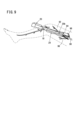
- FIG. 1 is a configuration diagram of a blood vessel collection system according to a first embodiment.
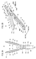
- 2A is a side view of the vicinity of the distal end of the blood vessel collection device of FIG. 1
- FIG. 2B is a perspective view of the jaw structure of FIG. 2A from the distal end.
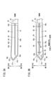
- 3A is a plan view of the upper jaw portion of FIG. 2A viewed from the clamping surface
- FIG. 3B is a plan view of the lower jaw portion of FIG. 2A viewed from the clamping surface.
- FIG. 4 is a side view showing the jaw structure removed from the cylindrical body.
- FIG. 5A is a view showing the jaw structure in a closed state as seen from the first side
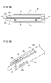
- FIG. 5B is a perspective view showing the cutter blade with the jaw structure removed from the cylindrical body.
- FIG. 6A is a perspective view showing the clamping surface of the upper jaw, the clamping surface of the lower jaw, and the cutter blade in an open state
- FIG. 6B shows the jaw structure of FIG. 6A in a closed state
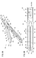
- FIG. FIG. 7A is a perspective view with the upper jaw removed, showing a state in which the cutter blade is retracted toward the proximal end
- FIG. 7B is a perspective view with the upper jaw removed, showing a state in which the cutter blade protrudes toward the distal end.
- FIG. 8A is an explanatory diagram of a marking step in a blood vessel collection method
- FIG. 8B is an explanatory diagram of a step of dissecting a blood vessel using a blood vessel dissection device.
- FIG. 9 is an explanatory diagram of the process of collecting a blood vessel with the blood vessel collection device of FIG. 1.
- 10A is a plan view showing a modified example of the upper jaw part of FIG. 3A
- FIG. 10B is a plan view showing a modified example of the lower jaw part of FIG. 3B.
- the blood vessel harvesting system 10 shown in FIG. 1 is an EVH system used for EVH (Endoscopic Vessel Harvesting).
- the blood vessel collection system 10 includes a display device 12, a high-frequency power source 14, a pneumoperitoneum device 16, a trocar 18, an imaging device 20 (endoscope), a blood vessel dissection device 22, and a blood vessel collection device 24. .
- the display device 12 is connected to the imaging device 20.
- the display device 12 displays images captured by the imaging device 20.
- High frequency power supply 14 supplies high frequency power to blood vessel collection device 24 to ablate tissue (blood vessel 90 or branch blood vessel 96).
- the pneumoperitoneum device 16 supplies carbon dioxide gas to the blood vessel ablation device 22 .
- the imaging device 20 includes a cylindrical body 20a and a camera 20b attached to the tip of the cylindrical body 20a.
- the imaging device 20 is inserted into a patient's body together with a blood vessel dissection device 22 or a blood vessel harvesting device 24 to image the work site.
- Trocar 18 is inserted into the incision near the blood vessel. Trocar 18 facilitates the introduction of imaging device 20, vessel ablation device 22, and vessel harvesting device 24 into the body. The trocar 18 is fixed to the skin by a clip 18a.
- the blood vessel ablation device 22 includes a cylindrical body 22a and a conical ablation portion 22b attached to the tip of the cylindrical body 22a.
- the cylindrical body 22a has an ejection hole 22c near its tip for releasing carbon dioxide gas.
- the blood vessel dissection device 22 dissects the blood vessel 90 and the peripheral tissue 92 around it at the dissection portion 22b.
- the blood vessel ablation device 22 forms a cavity 94 around the blood vessel 90 by carbon dioxide ejected from the ejection hole 22c (see FIG. 8B).
- the blood vessel sampling device 24 of this embodiment includes a cylindrical body 24a and a jaw structure 26 attached to the tip of the cylindrical body 24a.
- the cylindrical body 24a is a cylindrical member extending in the direction of the axis, and has wiring (not shown) for flowing high-frequency power therein and an operating wire (not shown) or an operating rod (not shown) for operating the jaw structure 26. accommodate.
- the blood vessel harvesting device 24 cuts the branch blood vessel 96 of the blood vessel 90 separated by the jaw structure 26.
- the jaw structure 26 has a function of cutting the branch blood vessel 96 by ablating the branch blood vessel 96 using high-frequency power to stop bleeding. Details of the jaw structure 26 will be explained later.
- the blood vessel sampling device 24 has a manipulation hub 28 at its proximal end.
- the operation hub 28 has a cutter operation section 28a, a jaw operation section 28b, and an energization switch 28c.
- the cutter operation section 28a performs a movement operation of the cutter blade 34 in the axial direction, which will be described later.
- the jaw operating section 28b opens and closes the jaw structure 26.
- the energization switch 28c switches between supplying and stopping high-frequency power to the jaw structure 26.
- the jaw structure 26 has the following configuration.
- the jaw structure 26 is attached to the tip of the cylindrical body 24a.
- the cylindrical body 24a has a pair of notched grooves 24b, which are partially cut out in the circumferential direction, at the distal end thereof.
- the pair of notch grooves 24b are arranged 180 degrees apart in the circumferential direction.
- Each notch groove 24b extends in the direction of the axis.
- the jaw structure 26 is accommodated in the notch groove 24b.
- the cylindrical body 24a has a pair of support portions 24c extending toward the tip between the pair of guide grooves 24d.
- the support portion 24c supports the jaw structure 26.
- the support portion 24c has a guide groove 24d and an opening/closing pin attachment hole 24e.
- the guide groove 24d is located on the tip side of the opening/closing pin attachment hole 24e.
- the guide groove 24d extends in the direction of the axis.
- the opening/closing pin attachment hole 24e has a circular shape.
- the center positions of the guide groove 24d and the opening/closing pin mounting hole 24e are offset by 90 degrees in the circumferential direction of the cylindrical body 24a with respect to the center of the notch groove 24b.
- the jaw structure 26 includes an upper jaw assembly 30, a lower jaw assembly 32, and a cutter blade 34.
- the upper jaw assembly 30 and the lower jaw assembly 32 are connected via a shaft pin 36 and an opening/closing pin 38.
- Axial pin 36 is fixed to upper jaw assembly 30 and lower jaw assembly 32.
- Axial pin 36 provides a center of rotation for upper jaw assembly 30 and lower jaw assembly 32.
- the shaft pin 36 is inserted into the guide groove 24d of the cylindrical body 24a.
- the guide groove 24d is a groove extending in the axial direction, and allows the shaft pin 36 to move in the axial direction.
- the shaft pin 36 moves in the guide groove 24d as the jaw structure 26 is displaced in the axial direction.
- the opening/closing pin 38 is a pin fixed to the cylindrical body 24a.
- the opening/closing pin 38 is displaced relative to the upper jaw assembly 30 and the lower jaw assembly 32 as the jaw structure 26 is displaced in the axial direction.
- the opening/closing pin 38 is inserted into the first sliding groove 30a of the upper jaw assembly 30 and the second sliding groove 32a of the lower jaw assembly 32.
- the opening/closing pin 38 slides in the first sliding groove 30a and the second sliding groove 32a when the jaw structure 26 moves forward or backward in the direction of the axis of the cylindrical body 24a.
- the upper jaw assembly 30 and the lower jaw assembly 32 rotate according to the position of the opening/closing pin 38 in the first sliding groove 30a and the second sliding groove 32a, and the jaw structure 26 opens and closes.
- the upper jaw assembly 30 has an upper jaw part 40 and a base part 42.
- the upper jaw part 40 has a clamping surface 41 located on the distal end side and perpendicular to the rotation direction.
- the base portion 42 is located on the base end side of the upper jaw portion 40 and is integrally connected to the upper jaw portion 40.
- the base 42 has a flat sliding surface 42a in a direction perpendicular to the clamping surface 41.
- the base 42 has a shaft hole 42c and a first sliding groove 30a.
- the shaft pin 36 is inserted through the shaft hole 42c.
- the shaft hole 42c becomes the rotation center of the upper jaw assembly 30.
- the first sliding groove 30a extends obliquely.
- the opening/closing pin 38 passes through the first sliding groove 30a.
- the upper jaw part 40 has a support body 44, a main body part 46, and a flat electrode 48.
- the support 44 is integrally connected to the base 42 and is made of the same material (for example, metal) as the base 42.
- the support body 44 supports the main body portion 46 .
- the main body portion 46 is formed of an insulating material such as resin.
- the main body portion 46 occupies most of the upper jaw portion 40.
- the main body portion 46 extends slightly inclined with respect to the direction of the axis.
- the main body portion 46 is supported by the support body 44 .
- the main body part 46 of the upper jaw part 40 has a first side surface 43a in a first direction perpendicular to the axis, and a second side surface 43b in a second direction opposite to the first direction.
- the centerline of the main body portion 46 is inclined toward the first direction with respect to the axis of the cylindrical body 24a.
- the first side surface 43 a has a gently arcuate curved surface 45 a that is convex with respect to the cutter groove 49 .
- the curved surface 45a of the first side surface 43a has a top portion 45b closest to the cutter groove 49 at the base end.
- the second side surface 43b extends parallel to the cutter groove 49.
- the position of the top portion 45b is not limited to the base end portion of the curved surface 45a.
- the upper jaw part 40 and the lower jaw part 50 may have a top part 45b near the middle part in the axial direction of the curved surface 45a of the first side surface 43a.
- the main body portion 46 has a distal end portion 46c that protrudes beyond the support body 44 at its distal end. Since the upper jaw portion 40 extends obliquely in the first direction with respect to the axis, the tip portion 46c is biased in the first direction with respect to the axis. Since the inclination of the upper jaw part 40 is slight, a portion of the distal end part 46c in the width direction overlaps with the axis of the cylindrical body 24a. Since the upper jaw part 40 has a slight inclination, the operating force can be easily concentrated on the distal end part 46c, and the operation to separate the blood vessel and the surrounding tissue can be easily performed.
- the tip portion 46c has a first inclined surface 47a and a second inclined surface 47b that are inclined with respect to the direction of the axis, and a ridgeline portion 47c.
- the first inclined surface 47a is a surface inclined toward the first direction, and is adjacent to the first side surface 43a.
- the second inclined surface 47b is a surface inclined toward the second direction, and is adjacent to the second side surface 43b.
- the ridgeline portion 47c is formed as a side where the first inclined surface 47a and the second inclined surface 47b intersect.
- the ridgeline portion 47c is located at the tip of the upper jaw assembly 30 and extends in a direction perpendicular to the clamping surface 41.
- the length of the first inclined surface 47a is shorter than the length of the second inclined surface 47b.
- the base end of the first inclined surface 47a is located closer to the distal end in the axial direction than the base end of the second inclined surface 47b.
- the first inclined surface 47a and the second inclined surface 47b intersect at an acute angle at the ridge line portion 47c.
- a ridgeline portion 47c can suitably separate the blood vessel from the surrounding tissue.
- the position of the ridgeline part 47c at the tip is spaced apart from the direction of the axis toward the first direction.
- the position of the ridge line part 47c is close to the position of the first side surface 43a, so that the visibility of the position where the peeling operation is performed is improved.
- the upper jaw part 40 has a clamping surface 41 facing the lower jaw part 50.
- a flat electrode 48 made of a conductive material is arranged on the holding surface 41.
- the plane electrode 48 is made of a plate-shaped metal plate attached to the main body 46 .
- the surface of the planar electrode 48 constitutes the clamping surface 41 .
- the clamping surface 41 has a cutter groove 49 extending along the axis.
- the cutter groove 49 penetrates the planar electrode 48 and reaches the inside of the main body portion 46 .
- the width of the cutter groove 49 is equal to or slightly larger than the thickness of the cutter blade 34.
- the cutter groove 49 extends along the axis of the cylindrical body 24a when the jaw structure 26 is closed.
- the cutter groove 49 guides the movement of the cutter blade 34 in the axial direction.
- the lower jaw assembly 32 includes a lower jaw portion 50 and a base portion 52.
- the lower jaw part 50 is located at the tip of the base part 52 and has a clamping surface 41 facing the upper jaw part 40 .
- the base portion 52 is located on the base end side of the lower jaw portion 50 and is integrally connected to the lower jaw portion 50.
- the base 52 has a flat sliding surface 52a in a direction perpendicular to the clamping surface 41.
- the sliding surface 52a slides on the sliding surface 42a of the upper jaw assembly 30.
- the base 52 has a shaft hole 52c and a second sliding groove 32a.
- the shaft pin 36 is inserted through the shaft hole 52c.
- the shaft hole 52c becomes the rotation center of the lower jaw assembly 32.
- the second sliding groove 32a extends obliquely in the opposite direction to the first sliding groove 30a.
- the opening/closing pin 38 passes through the second sliding groove 32a.
- the lower jaw portion 50 includes a support body 44, a main body portion 46, a flat electrode 48, and a cutter groove 49. Since the lower jaw part 50 has a vertically symmetrical shape with respect to the upper jaw part 40, a detailed description of its shape will be omitted. In the lower jaw part 50, the same components as in the upper jaw part 40 are given the same reference numerals.
- the lower jaw portion 50 has a spacer 60 on the planar electrode 48 . The spacer 60 protrudes from the surface (the sandwiching surface 41) of the planar electrode 48.
- the spacer 60 protrudes from the planar electrode 48 at a height of, for example, 0.1 mm.
- the spacer 60 is, for example, a cylindrical insulating material.
- a plurality of spacers 60 are arranged at intervals in the direction in which the cutter groove 49 extends. As shown in FIG. 5A, the spacer 60 prevents the planar electrodes 48 of the upper jaw 40 and the lower jaw 50 from coming into contact with each other when the jaw structure 26 is closed, thereby preventing short circuits. Further, the spacer 60 prevents defective cutting due to escape displacement of the blood vessel 90 or branch blood vessel 96 when the cutter blade 34 is made to protrude along the cutter groove 49 to cut the blood vessel 90 or the branch blood vessel 96.
- the distal end spacer 60a located at the distal end side of the plurality of spacers 60 is located on the distal end side in the axial direction from the distal end portion 49a of the cutter groove 49.
- the tip spacer 60a is located on a line 80 that passes through the ridgeline 47c and is parallel to the axial direction.
- the planar electrode 48 is more likely to come into contact with the portion closer to the tip.
- the tip spacer 60a is disposed at the above-mentioned portion to prevent the planar electrodes 48 from coming into contact with each other at the tip portions of the upper jaw portion 40 and the lower jaw portion 50.
- the upper jaw assembly 30 and the lower jaw assembly 32 are rotatably connected at their respective bases 42 and 52 by a shaft pin 36 and an opening/closing pin 38.
- a cutter blade 34 is disposed between the base 42 of the upper jaw assembly 30 and the base 52 of the lower jaw assembly 32.
- the jaw structure 26 is movable in the axial direction with respect to the cylindrical body 24a. When the jaw structure 26 is located on the proximal side, the jaw structure 26 opens and the upper jaw portion 40 and the lower jaw portion 50 are separated, as shown in FIG. 6A. Displacing the jaw structure 26 axially to the distal end causes the jaw structure 26 to close, as shown in FIG. 6B. Movement of the jaw structure 26 is effected by the jaw operating portion 28b of the operating hub 28 in FIG.
- the clamping surface 41 of the upper jaw part 40 and the clamping surface 41 of the lower jaw part 50 have an inclination angle such that the gap becomes wider toward the proximal end.
- the gap d1 at the tip of the upper jaw part 40 and the lower jaw part 50 is smaller than the gap d2 at the base end. Therefore, in the jaw structure 26, the upper jaw part 40 and the lower jaw part 50 close from the distal end side.
- the cutter blade 34 extends in the direction of the axis of the cylindrical body 24a.
- the cutter blade 34 can be projected toward the tip in the axial direction by the cutter operation portion 28a of the operation hub 28 shown in FIG.
- the cutter blade 34 is biased toward the proximal end, and is located at the proximal end in an initial state, as shown in FIG. 7A.
- the cutter blade 34 protrudes with the jaw structure 26 closed, the cutter blade 34 protrudes toward the tip in the axial direction along the cutter groove 49 and is sandwiched between the jaw structures 26, as shown in FIG.
- the blood vessel 90 or branch blood vessel 96 is cut.
- the blood vessel sampling device 24 of this embodiment is configured as described above.
- the blood vessel sampling system 10 is used, for example, in the following blood vessel sampling method.
- the blood vessel collection method includes a marking step, as shown in FIG. 8A. This process includes the step of confirming the position of the saphenous vein on the shin and the step of making a marking of approximately 2.5 cm at the lower part of the knee joint.
- the blood vessel sampling method proceeds to the step of inserting the trocar 18.
- an incision is made at the marked location, and then the trocar 18 is inserted.
- the trocar 18 is fixed to the skin by a clip 18a.
- the blood vessel collection method proceeds to a blood vessel dissection step, as shown in FIG. 8B.
- a blood vessel ablation device 22 and an imaging device 20 are inserted through the trocar 18.
- This step includes an operation of peeling off the surrounding tissue 92 from the blood vessel 90 with the peeling section 22b while imaging the blood vessel 90 with the camera 20b of the imaging device 20.
- the blood vessel 90 is ablated by the blood vessel ablation device 22 while ejecting carbon dioxide gas from the ejection hole 22c near the ablation portion 22b.
- This step forms a cavity around the blood vessel 90.
- the blood vessel ablation device 22 and the imaging device 20 are removed from the body.
- the blood vessel sampling method proceeds to a blood vessel sampling step, as shown in FIG.
- the blood vessel sampling step is performed using the blood vessel sampling device 24. This step includes cutting the branch blood vessel 96 with the blood vessel harvesting device 24. Blood vessel harvesting device 24 and imaging device 20 are inserted into a cavity around blood vessel 90 through trocar 18 .
- the imaging device 20 is disposed on the proximal side of the blood vessel sampling device 24 and images the jaw structure 26 of the blood vessel sampling device 24 from the proximal side.
- Cutting the branch blood vessel 96 using the blood vessel collection device 24 is performed by the following steps. First, a step of placing the jaw structure 26 in an open state at the position of the branch blood vessel 96 is performed while observing with the imaging device 20. Thereafter, a step is performed in which the jaw structure 26 is closed and the branch blood vessel 96 is sandwiched between the upper jaw part 40 and the lower jaw part 50. A step of supplying high frequency power to the blood vessel sampling device 24 is then performed. High frequency power is supplied between the flat electrode 48 of the upper jaw 40 and the flat electrode 48 of the lower jaw 50 to ablate the pinched branch blood vessel 96 and stop bleeding. Next, the step of cutting the branch blood vessel 96 is performed by advancing the cutter blade 34 along the cutter groove 49.
- the blood vessel collection device 24 is further advanced to cut another branch blood vessel 96.
- the jaw structure 26 when the jaw structure 26 is closed, a ridgeline portion 47c appears at the tip. Therefore, in the blood vessel harvesting process, if a part of the blood vessel 90 is found where the surrounding tissue 92 is not sufficiently peeled off, the surrounding tissue 92 can be peeled off using the ridge line portion 47c. At this time, the jaw structure 26 is biased in the first direction with respect to the direction of the axis of the cylindrical body 24a, and the ridgeline portion 47c is deviated from the direction of the axis.
- the blood vessel sampling device 24 allows the state of the vicinity of the distal end of the jaw structure 26 to be visually recognized with the imaging device 20 disposed on the proximal end side. Further, the first side surface 43a curved to form a convex shape toward the cutter groove 49 further improves visibility of the vicinity of the tip by the imaging device 20. In this manner, the vessel harvesting device 24 facilitates performing ablation of the surrounding tissue 92 that is left behind.
- the blood vessel harvesting device 24 and the imaging device 20 are withdrawn from the patient's body. Thereafter, the blood vessel collection method is completed by pulling out the blood vessel 90 from the incision.
- the blood vessel sampling device 24 of this embodiment described above is summarized below.
- One aspect of the invention is to have a cylindrical body 24a extending along the axis, and a jaw that is attached to the tip of the cylindrical body and includes an upper jaw part 40 and a lower jaw part 50, and the upper jaw part and the lower jaw part open and close.
- a structure 26 a cutter blade 34 disposed between the upper jaw part and the lower jaw part and moving in the direction of the axis along a cutter groove 49 of the upper jaw part and the lower jaw part; has a ridgeline portion 47c formed at the tip of the upper jaw portion and the tip of the lower jaw portion, respectively, and the upper jaw portion and the lower jaw portion are biased in a first direction that is a radial direction with respect to the axis.
- the blood vessel harvesting device 24 has an asymmetrical shape and the ridges are spaced apart in the first direction with respect to the axis.
- the upper jaw part and the lower jaw part have a first inclined surface 47a adjacent to the first direction of the ridgeline part and a second direction of the ridgeline part opposite to the first direction.
- an adjacent second inclined surface 47b, and the ridgeline portion may be an intersection line of the first inclined surface and the second inclined surface.
- This blood vessel collection device has a sharp ridgeline at the tip, so that the blood vessel and surrounding tissue can be easily separated.
- the first inclined surface and the second inclined surface may intersect at an acute angle at the ridge line.
- a blood vessel collection device having such a ridgeline can easily detach surrounding tissue from a blood vessel.
- the upper jaw part and the lower jaw part have a first side surface 43a adjacent to the proximal side of the first inclined surface, and the first side surface is convex with respect to the axis. It may have a curved surface 45a along an arc.
- the first side surface does not get in the way when imaging the distal end of the jaw structure from the proximal end, improving visibility in the vicinity of the distal end.
- the first side surface may approach the axis as it approaches the base end, and the apex 45b of the arc may be located at the base end of the first side surface.
- This blood vessel sampling device has excellent visibility near the tip.
- the curved surface of the first side surface may have an apex closest to the axis at an intermediate portion in the direction of the axis.
- This blood vessel sampling device has excellent visibility near the tip.
- each of the upper jaw part and the lower jaw part has a flat electrode 48 made of a conductive material on surfaces facing each other, and at least one of the flat electrodes of the upper jaw part and the flat electrode of the lower jaw part has a flat electrode 48 made of a conductive material.
- a spacer 60 made of an insulating material may be provided protruding from the planar electrode. This blood vessel sampling device can prevent short circuits of the planar electrodes, supply sufficient high-frequency power to the blood vessel, and enable reliable hemostasis.
- the upper jaw part and the lower jaw part may have an inclination angle such that a gap between surfaces facing each other when the jaw structure is closed widens toward the proximal end.
- a jaw structure that includes a cylindrical body extending along an axis, and an upper jaw part and a lower jaw part that are attached to the tip of the cylindrical body, and the upper jaw part and the lower jaw part open and close.
- a cutter blade that is disposed between the upper jaw part and the lower jaw part and moves in the direction of the axis along the cutter groove of the upper jaw part and the lower jaw part, is a distal end that extends toward the distal end while being inclined in a first direction that is a radial direction with respect to the axis, and is located on the distal side of the cutter groove of the upper jaw portion and the lower jaw portion.
- portion of the blood vessel sampling device is within a range that overlaps the axis.
- the above blood vessel collection device has a slight curvature at the tips of the maxillary and mandibular portions within the range where they overlap with the axis, making it easier to concentrate the operating force on the tips, making it easier to separate the blood vessels and surrounding tissues. I can do it.
- the jaw structure is curved, it is easy to visually recognize the operation site at the distal end from the imaging device on the proximal end side.
Landscapes
- Health & Medical Sciences (AREA)
- Life Sciences & Earth Sciences (AREA)
- Surgery (AREA)
- Engineering & Computer Science (AREA)
- Medical Informatics (AREA)
- Veterinary Medicine (AREA)
- Biomedical Technology (AREA)
- Heart & Thoracic Surgery (AREA)
- Nuclear Medicine, Radiotherapy & Molecular Imaging (AREA)
- Molecular Biology (AREA)
- Animal Behavior & Ethology (AREA)
- General Health & Medical Sciences (AREA)
- Public Health (AREA)
- Physics & Mathematics (AREA)
- Plasma & Fusion (AREA)
- Otolaryngology (AREA)
- Ophthalmology & Optometry (AREA)
- Rheumatology (AREA)
- Surgical Instruments (AREA)
Priority Applications (2)
| Application Number | Priority Date | Filing Date | Title |
|---|---|---|---|
| JP2024516281A JPWO2023204231A1 (cg-RX-API-DMAC7.html) | 2022-04-21 | 2023-04-19 | |
| US18/921,920 US20250040983A1 (en) | 2022-04-21 | 2024-10-21 | Vessel harvesting device |
Applications Claiming Priority (2)
| Application Number | Priority Date | Filing Date | Title |
|---|---|---|---|
| JP2022-070082 | 2022-04-21 | ||
| JP2022070082 | 2022-04-21 |
Related Child Applications (1)
| Application Number | Title | Priority Date | Filing Date |
|---|---|---|---|
| US18/921,920 Continuation US20250040983A1 (en) | 2022-04-21 | 2024-10-21 | Vessel harvesting device |
Publications (1)
| Publication Number | Publication Date |
|---|---|
| WO2023204231A1 true WO2023204231A1 (ja) | 2023-10-26 |
Family
ID=88419826
Family Applications (1)
| Application Number | Title | Priority Date | Filing Date |
|---|---|---|---|
| PCT/JP2023/015551 Ceased WO2023204231A1 (ja) | 2022-04-21 | 2023-04-19 | 血管採取デバイス |
Country Status (3)
| Country | Link |
|---|---|
| US (1) | US20250040983A1 (cg-RX-API-DMAC7.html) |
| JP (1) | JPWO2023204231A1 (cg-RX-API-DMAC7.html) |
| WO (1) | WO2023204231A1 (cg-RX-API-DMAC7.html) |
Citations (3)
| Publication number | Priority date | Publication date | Assignee | Title |
|---|---|---|---|---|
| US20150190191A1 (en) * | 2014-01-07 | 2015-07-09 | Ethicon Endo-Surgery, Inc. | Electrosurgical Sealing and Transecting Devices and Methods with Improved Application of Compressive Force |
| JP2019513470A (ja) * | 2016-04-15 | 2019-05-30 | ジャストライト サージカル,リミティド ライアビリティ カンパニー | 電気外科手術用シーラー及び分割器 |
| US20190365458A1 (en) * | 2018-05-31 | 2019-12-05 | Intuitive Surgical Operations, Inc. | Surgical instruments having a jaw locking mechanism |
-
2023
- 2023-04-19 JP JP2024516281A patent/JPWO2023204231A1/ja active Pending
- 2023-04-19 WO PCT/JP2023/015551 patent/WO2023204231A1/ja not_active Ceased
-
2024
- 2024-10-21 US US18/921,920 patent/US20250040983A1/en active Pending
Patent Citations (3)
| Publication number | Priority date | Publication date | Assignee | Title |
|---|---|---|---|---|
| US20150190191A1 (en) * | 2014-01-07 | 2015-07-09 | Ethicon Endo-Surgery, Inc. | Electrosurgical Sealing and Transecting Devices and Methods with Improved Application of Compressive Force |
| JP2019513470A (ja) * | 2016-04-15 | 2019-05-30 | ジャストライト サージカル,リミティド ライアビリティ カンパニー | 電気外科手術用シーラー及び分割器 |
| US20190365458A1 (en) * | 2018-05-31 | 2019-12-05 | Intuitive Surgical Operations, Inc. | Surgical instruments having a jaw locking mechanism |
Also Published As
| Publication number | Publication date |
|---|---|
| US20250040983A1 (en) | 2025-02-06 |
| JPWO2023204231A1 (cg-RX-API-DMAC7.html) | 2023-10-26 |
Similar Documents
| Publication | Publication Date | Title |
|---|---|---|
| KR100595803B1 (ko) | 고주파 나이프 및 내시경 장치 | |
| US6660016B2 (en) | Integrated vein dissector and cauterizing apparatus for endoscopic harvesting of blood vessels | |
| JP5636449B2 (ja) | 高周波処置具 | |
| EP1323392B1 (en) | Treatment device for cutting living tissue | |
| CA2273925C (en) | Mechanical and electrical endoscopic surgical instrument | |
| US7077803B2 (en) | Living tissue harvesting apparatus | |
| JP5244804B2 (ja) | 筒状の軸機器 | |
| JP5180081B2 (ja) | 内視鏡用処置具 | |
| EP2147653A1 (en) | Flexible endoscopic catheter with an end effector for coagulating and transecting tissue | |
| EP3962377B1 (en) | Unitary endoscopic vessel harvesting devices with a visual cue to identify cutting elements orientation | |
| KR19980064465A (ko) | 혈관 특히 관상 동맥 우회 이식용 내부 유방 동맥의 수확을 위한 전기 외과 장치 | |
| GB2414185A (en) | Morcellating device using cutting electrodes on end-face of tube | |
| JP2005246058A (ja) | 内視鏡的血管採取装置 | |
| WO2011114602A1 (ja) | 内視鏡処置具 | |
| EP3737300B1 (en) | Vessel harvesting apparatus | |
| US10363087B2 (en) | Tissue resection device | |
| EP1948027B1 (en) | Tissue cutting devices having hemostasis capability | |
| WO2023204231A1 (ja) | 血管採取デバイス | |
| JP5535862B2 (ja) | 内視鏡用高周波剥離ナイフ装置 | |
| WO2023204232A1 (ja) | 血管採取デバイス | |
| JP2001061848A (ja) | 高周波処置具 | |
| WO2023204233A1 (ja) | 血管採取デバイス | |
| CN111184572A (zh) | 组织剥离器具 | |
| US20070282336A1 (en) | Bipolar high-frequency treatment tool for endoscope | |
| CN107736936A (zh) | 喉部双极钳式切割消融刀 |
Legal Events
| Date | Code | Title | Description |
|---|---|---|---|
| 121 | Ep: the epo has been informed by wipo that ep was designated in this application |
Ref document number: 23791879 Country of ref document: EP Kind code of ref document: A1 |
|
| ENP | Entry into the national phase |
Ref document number: 2024516281 Country of ref document: JP Kind code of ref document: A |
|
| NENP | Non-entry into the national phase |
Ref country code: DE |
|
| 122 | Ep: pct application non-entry in european phase |
Ref document number: 23791879 Country of ref document: EP Kind code of ref document: A1 |