WO2023203668A1 - 作業飛行体 - Google Patents
作業飛行体 Download PDFInfo
- Publication number
- WO2023203668A1 WO2023203668A1 PCT/JP2022/018265 JP2022018265W WO2023203668A1 WO 2023203668 A1 WO2023203668 A1 WO 2023203668A1 JP 2022018265 W JP2022018265 W JP 2022018265W WO 2023203668 A1 WO2023203668 A1 WO 2023203668A1
- Authority
- WO
- WIPO (PCT)
- Prior art keywords
- work
- target position
- control unit
- working
- aircraft
- Prior art date
Links
- RZVHIXYEVGDQDX-UHFFFAOYSA-N 9,10-anthraquinone Chemical group C1=CC=C2C(=O)C3=CC=CC=C3C(=O)C2=C1 RZVHIXYEVGDQDX-UHFFFAOYSA-N 0.000 claims description 36
- 238000001514 detection method Methods 0.000 claims description 36
- 230000007613 environmental effect Effects 0.000 claims description 28
- 238000012544 monitoring process Methods 0.000 claims description 19
- 238000012806 monitoring device Methods 0.000 claims description 17
- 239000000463 material Substances 0.000 claims description 12
- 230000032258 transport Effects 0.000 claims description 12
- 238000003306 harvesting Methods 0.000 claims description 11
- 230000001846 repelling effect Effects 0.000 claims description 11
- 239000000126 substance Substances 0.000 claims description 10
- 230000006872 improvement Effects 0.000 claims description 7
- 230000004720 fertilization Effects 0.000 claims description 3
- 238000010899 nucleation Methods 0.000 claims description 3
- 238000003971 tillage Methods 0.000 claims description 3
- 230000005540 biological transmission Effects 0.000 description 41
- 230000007246 mechanism Effects 0.000 description 25
- 230000008859 change Effects 0.000 description 7
- 230000033001 locomotion Effects 0.000 description 7
- 238000005507 spraying Methods 0.000 description 7
- 238000010276 construction Methods 0.000 description 6
- 238000013459 approach Methods 0.000 description 4
- 238000010586 diagram Methods 0.000 description 3
- 238000000034 method Methods 0.000 description 3
- 239000007921 spray Substances 0.000 description 3
- 241000209094 Oryza Species 0.000 description 2
- 235000007164 Oryza sativa Nutrition 0.000 description 2
- 235000013339 cereals Nutrition 0.000 description 2
- 238000004891 communication Methods 0.000 description 2
- 239000003814 drug Substances 0.000 description 2
- 230000000694 effects Effects 0.000 description 2
- 238000005516 engineering process Methods 0.000 description 2
- 239000000446 fuel Substances 0.000 description 2
- 238000005259 measurement Methods 0.000 description 2
- 230000008569 process Effects 0.000 description 2
- 235000009566 rice Nutrition 0.000 description 2
- 230000001629 suppression Effects 0.000 description 2
- XLYOFNOQVPJJNP-UHFFFAOYSA-N water Substances O XLYOFNOQVPJJNP-UHFFFAOYSA-N 0.000 description 2
- 241000238631 Hexapoda Species 0.000 description 1
- 238000004378 air conditioning Methods 0.000 description 1
- 230000003542 behavioural effect Effects 0.000 description 1
- 230000000903 blocking effect Effects 0.000 description 1
- 238000007664 blowing Methods 0.000 description 1
- 239000003795 chemical substances by application Substances 0.000 description 1
- 238000001816 cooling Methods 0.000 description 1
- 229940079593 drug Drugs 0.000 description 1
- 241001233061 earthworms Species 0.000 description 1
- 239000003337 fertilizer Substances 0.000 description 1
- 239000000796 flavoring agent Substances 0.000 description 1
- 235000019634 flavors Nutrition 0.000 description 1
- 230000010006 flight Effects 0.000 description 1
- 238000007667 floating Methods 0.000 description 1
- 239000003205 fragrance Substances 0.000 description 1
- 239000003721 gunpowder Substances 0.000 description 1
- 230000007257 malfunction Effects 0.000 description 1
- 238000002844 melting Methods 0.000 description 1
- 230000008018 melting Effects 0.000 description 1
- 239000003973 paint Substances 0.000 description 1
- 239000000575 pesticide Substances 0.000 description 1
- 230000002265 prevention Effects 0.000 description 1
- 230000002040 relaxant effect Effects 0.000 description 1
- 230000003584 silencer Effects 0.000 description 1
- 238000004804 winding Methods 0.000 description 1
Images


Classifications
-
- B—PERFORMING OPERATIONS; TRANSPORTING
- B64—AIRCRAFT; AVIATION; COSMONAUTICS
- B64C—AEROPLANES; HELICOPTERS
- B64C13/00—Control systems or transmitting systems for actuating flying-control surfaces, lift-increasing flaps, air brakes, or spoilers
- B64C13/02—Initiating means
- B64C13/16—Initiating means actuated automatically, e.g. responsive to gust detectors
- B64C13/18—Initiating means actuated automatically, e.g. responsive to gust detectors using automatic pilot
-
- B—PERFORMING OPERATIONS; TRANSPORTING
- B64—AIRCRAFT; AVIATION; COSMONAUTICS
- B64C—AEROPLANES; HELICOPTERS
- B64C39/00—Aircraft not otherwise provided for
- B64C39/02—Aircraft not otherwise provided for characterised by special use
-
- B—PERFORMING OPERATIONS; TRANSPORTING
- B64—AIRCRAFT; AVIATION; COSMONAUTICS
- B64D—EQUIPMENT FOR FITTING IN OR TO AIRCRAFT; FLIGHT SUITS; PARACHUTES; ARRANGEMENTS OR MOUNTING OF POWER PLANTS OR PROPULSION TRANSMISSIONS IN AIRCRAFT
- B64D1/00—Dropping, ejecting, releasing, or receiving articles, liquids, or the like, in flight
- B64D1/16—Dropping or releasing powdered, liquid, or gaseous matter, e.g. for fire-fighting
-
- B—PERFORMING OPERATIONS; TRANSPORTING
- B64—AIRCRAFT; AVIATION; COSMONAUTICS
- B64D—EQUIPMENT FOR FITTING IN OR TO AIRCRAFT; FLIGHT SUITS; PARACHUTES; ARRANGEMENTS OR MOUNTING OF POWER PLANTS OR PROPULSION TRANSMISSIONS IN AIRCRAFT
- B64D47/00—Equipment not otherwise provided for
Definitions
- the present invention relates to a work aircraft and a work system that performs work using the aircraft.
- Patent Document 1 discloses an aircraft support device equipped with a spraying device for spraying pesticides and the like as an example of agricultural work.
- a working aircraft includes a flying object, a working device capable of performing a predetermined work, and a work control unit that controls the working device, and the control means is configured to position the working device at a work target position.
- the control means is configured to position the working device at a work target position.
- the driving of the working device can be suppressed. Therefore, work can be performed on an appropriate work target position.
- the work control unit allows the working device to be driven when the scheduled work time for performing the work on the work target position is reached, and when it is not the scheduled work time, the work control unit allows the driving of the working device. It is preferable to suppress the drive.
- the working device includes a notification means for notifying that the work device is not located at the work target position.
- the notification means when the working device is displaced from a state where it is located at the work target position to a state where it is not located at the work target position, the notification means It is preferable that the notification be made by.
- the present invention further includes a flight control unit that controls the flight of the flying object, and the flight control unit is configured to perform preset settings based on at least one of an environmental condition surrounding the work target position and a prediction of the environmental condition. It is preferable to change the working route.
- the environmental condition is at least one of wind direction and wind speed.
- the work control section controls the work device based on the three-dimensional shape of the work object.
- a flight control section is provided to control the flight of the flying object, and the flight control section controls the flying object based on the three-dimensional shape of the work target.
- the working device includes at least one of a tilling device, a chemical application device, a fertilization device, a seeding device, a seedling transplanting device, a crop harvesting device, and a snow removal device.
- the work device includes a work environment improvement device that improves the work environment in at least one of the work object and the surrounding area of the work object.
- the work device includes a monitoring device that monitors at least one of a work object and a surrounding area of the work object, and a repelling device that repels the monitoring object based on a monitoring result of the monitoring device. It is preferable to have one.
- the work device includes a monitoring device that monitors at least one of a work object and a surrounding area of the work object, and a reporting device that makes a notification based on the monitoring result of the monitoring device. suitable.
- the work device includes a monitoring device that monitors at least one of a work object and a surrounding area of the work object, and a marking device that marks the monitoring object based on a monitoring result of the monitoring device. It is preferable to have the following.
- the working device includes at least one of a material conveying device that conveys materials to another working device, and a harvest conveying device that conveys harvested products from the other working device. .
- the work system of the present invention is a work system that performs work using a flying object, and includes a flying object, a working device capable of performing a predetermined work, and information regarding the position of the flying object and the position of the working device.
- a positioning device that acquires certain own machine position information, a work control unit that controls the work device, and a work plan storage unit that stores work plan information, the work plan information including work target position information. and the work control unit allows the work device to be driven when the work device is located at the work target position based on the own machine position information and the work target position information, and When the working device is not located at the work target position, driving of the working device is suppressed.
- the driving of the work device can be suppressed based on the work target position information included in the work plan information. Therefore, work can be performed on an appropriate work target position.
- the work plan information includes scheduled work time information regarding the scheduled work time for performing the work on the work object, and the work control unit determines the scheduled work time based on the scheduled work time information. It is preferable to allow the working device to be driven when the scheduled work time is reached, and to suppress the driving of the working device when it is not the scheduled work time.
- the driving of the work equipment can be suppressed when the work is not scheduled, based on the scheduled work time information regarding the scheduled work time for performing the work on the work target included in the work plan information. I can do it.
- the scheduled work time information includes time-series target position data indicating the target position of at least one of the flying object and the working device within the work space at each point in the scheduled work time
- the flight control unit controls the flight of the flying object based on the time-series target position data.
- work in the work space can be automatically performed based on the time-series target position data.
- the work plan creation unit can suitably create a later work plan based on the information regarding the work results acquired by the work result acquisition unit.
- the subsequent work may include post-process work and work from the next year onwards.
- the present invention includes an environmental situation prediction unit that predicts an environmental situation around the work target position, and the environmental situation prediction unit includes an environmental situation detection device that detects an environmental state around the work target position.
- the environmental situation is predicted based on the environmental situation detected by the aircraft.
- FIG. 3 is a front view of the flight device.
- FIG. 2 is a plan view of the flight device.
- FIG. 1 is a block diagram showing the overall configuration of a work system.
- FIG. 3 is a front view of the flight device.
- FIG. 3 is a diagram illustrating an example of contents indicated by object information.
- FIG. 3 is a diagram showing an example of time-series target position data.
- FIG. 2 is a plan view of the flying object. It is a figure which shows an example of the flying object provided with another working device. It is a figure which shows an example of the flying object provided with another working device. It is a figure which shows an example of the flying object provided with another working device. It is a figure which shows an example of the flying object provided with another working device.
- the work system SY (see FIG. 3) in this embodiment includes the work aircraft 1 shown in FIGS. 1 and 2.
- the working flying object 1 includes a flying object 2, a working device 3, and four connection mechanisms 5.
- the flying object 2 is a multicopter that can fly alone. As shown in FIGS. 1 and 2, the flying object 2 includes a main body 20, a plurality of propellers 21, and a plurality of arms 25.
- the main body portion 20 has a circular shape in plan view.
- the plurality of arm sections 25 extend radially from the main body section 20 in the horizontal direction.
- a propeller 21 is attached to the free end of each arm portion 25.
- propellers 21 and arm portions 25 are not particularly limited, in this embodiment, four propellers 21 and four arm portions 25 are provided.
- the four arm sections 25 each extend from the main body section 20 to the left front, right front, left rear, and right rear.
- Each propeller 21 is driven by the driving force of an electric flight motor 22 (see FIG. 3).
- the flying object 2 can fly by driving each propeller 21.
- the flying object 2 can move vertically, longitudinally, and horizontally while floating in the air. Further, the flying object 2 is capable of stopped flight by driving each propeller 21.
- the flying object 2 can fly even when it is incorporated into the working flying object 1 or when it is removed from the working flying object 1.
- the working device 3 is a chemical sprayer A1.
- the chemical spraying machine A1 is capable of performing chemical spraying work on crops (corresponding to the "predetermined work" according to the present invention).
- the present invention is not limited thereto, and the work device 3 may be any type of device as long as it can perform the work. Further, the working device 3 can be replaced with various types of working devices 3 depending on the required work.
- the work system SY includes a work device 3 that can perform a predetermined work.
- each connection mechanism 5 may be, for example, a known wire. Further, each connection mechanism 5 extends upward from an electric winch 51 (corresponding to the "connection length changing section" according to the present invention). The upper end of each connection mechanism 5 is connected to the free end of the arm portion 25. The winch 51 is capable of winding up and letting out the connection mechanism 5.
- Each winch 51 is attached to the upper end of the working device 3.
- each winch 51 is attached to the left front part, the right front part, the left rear part, and the right rear part of the working device 3, respectively, in plan view.
- the flying object 2 is connected to the working device 3 via the connection mechanism 5. More specifically, the flying object 2 is connected to the working device 3 via a plurality of connection mechanisms 5.
- connection mechanism 5 As each winch 51 winds up the connection mechanism 5, the length of the connection mechanism 5 between the flying object 2 and the working device 3 is shortened. As a result, the working device 3 approaches the flying object 2. As a result, the working device 3 rises.
- the work system SY includes the winch 51 that changes the length of the connection mechanism 5 between the flying object 2 and the work device 3.
- the working device 3 can be raised and lowered relative to the flying object 2, as shown in FIG.
- the flying object 2 By driving each propeller 21, the flying object 2 can move together with the working device 3. Thereby, the flight device 1 can perform a predetermined work using the work device 3 while moving.
- the work system SY includes a flying object 2 that is connected to the work device 3 and is capable of moving the work device 3.
- the flying object 2 has a first battery 26 (corresponding to the "energy source” according to the present invention).
- the first battery 26 can store electric power (corresponding to "energy” according to the present invention). Further, the first battery 26 can supply power to the flight motor 22 and the winch 51. The flight motor 22 and the winch 51 can be driven by electric power supplied from the first battery 26 .
- the working device 3 has a second battery 30.
- the second battery 30 is capable of storing power.
- the working device 3 can be driven by the power of the second battery 30.
- the flying object 2 includes a first battery 26.
- the first battery 26 is capable of storing electric power (equivalent to "energy” according to the present invention). Further, the first battery 26 can supply power to the flight motor 22 and the winch 51. The flight motor 22 and the winch 51 can be driven by the power supplied from the first battery 26.
- the working device 3 has a second battery 30.
- the second battery 30 is capable of storing power.
- the working device 3 can be driven by the power of the second battery 30.
- the flying object 2 has a main unit 42. As shown in FIG. Although the main unit 42 is not particularly limited, it may be stored in the main body 20, for example.
- the main unit 42 has a control section 44.
- the control unit 44 is configured to control the position of the work device 3 in the work space.
- the control unit 44 will be explained in detail below.
- control section 44 includes a flight control section 31 and a relative position control section 32.
- the work system includes the control section 44 having the flight control section 31 and the relative position control section 32. That is, the work system includes a control section 44 having a flight control section 31.
- the flight control unit 31 is configured to control each flight motor 22. Thereby, the flight control unit 31 controls the flight of the flying object 2.
- the work system includes a flight control section 31 that controls the flight of the flying object 2.
- control unit 32 is configured to control each winch 51. Thereby, the control unit 32 controls the relative position of the flying object 2 and the working device 3.
- the work system includes a control unit 32 that controls the relative positions of the flying object 2 and the work device 3.
- control unit 32 can bring the working device 3 closer to the aircraft 2 by controlling each winch 51 so that each winch 51 winds up the connection mechanism 5. Further, the control unit 32 can move the working device 3 away from the flying object 2 by controlling each winch 51 so that each winch 51 draws out the connection mechanism 5.
- control unit 32 can control the attitude of the working device 3 with respect to the flying object 2.
- attitude of the working device 3 with respect to the flying object 2 corresponds to the relative position between the flying object 2 and the working device 3.
- control unit 32 controls the length of the two connection mechanisms 5 on the right side of the flight device 1 to be shorter than the two connection mechanisms 5 on the left side of the flight device 1.
- each winch 51 can be controlled. Thereby, the working device 3 assumes an inclined attitude with respect to the flying object 2.
- the relative position control unit 32 controls the relative position between the flying object 2 and the working device 3 by controlling the winch 51.
- the relative position control unit 32 can tilt the working device 3 to match the slope of the ground, as shown in FIG. 4.
- control unit 44 can control the flight of the flying object 2 using the flight control unit 31. Further, the control unit 44 can control the relative position of the flying object 2 and the working device 3 by the relative position control unit 32 .
- the control unit 44 controls the position of the working device 3 in the work space by integrally controlling the flight of the flying object 2 and controlling the relative position between the flying object 2 and the working device 3. .
- control unit 44 is configured to control the position of the work device 3 in the work space by controlling the flight of the flying object 2 by the flight control unit 31. More specifically, the control unit 44 controls the flight of the aircraft 2 using the flight control unit 31 and controls the relative position between the aircraft 2 and the work device 3 using the relative position control unit 32, thereby controlling the work. It is configured to control the position of the working device 3 in space.
- the main unit has a satellite positioning device 45.
- the satellite positioning device 45 receives GPS signals from artificial satellites used in GPS (Global Positioning System). Then, the satellite positioning device 45 calculates the position coordinates of the flight device 1 over time based on the received GPS signal.
- GPS Global Positioning System
- the satellite positioning device 45 does not need to use GPS.
- the satellite positioning device 45 may use GNSS (GLONASS, Galileo, Michibiki, BeiDou, etc.) other than GPS.
- GNSS GLONASS, Galileo, Michibiki, BeiDou, etc.
- the calculated positional coordinates of the flight device 1 over time are sent to the spatial position control unit 44.
- the main unit 42 also includes an acquisition section 47.
- the acquisition unit 47 acquires object information.
- the object information is information indicating the position and height of an object in the work space.
- the object is, for example, the ground, an obstacle, a crop, or the like. That is, the working flying object 1 (flying object 2 and working device 3) is controlled based on the three-dimensional shape of the work object.
- the work system includes the acquisition unit 47 that acquires object information that is information indicating the position and height of an object in the work space.
- the acquisition unit 47 may acquire object information from a management server (not shown) provided outside the work aircraft 1, for example, although it is not particularly limited. Further, for example, the acquisition unit 47 may acquire object information from a work vehicle such as a tractor or a combine harvester. Further, for example, the acquisition unit 47 includes an object sensor (not shown) that detects the position and height of an object around the work aircraft 1, and generates object information based on the detection result by this object sensor. By doing so, object information may be acquired. Further, the management server (not shown) may include a work plan storage unit that stores work plan information, and acquire object information based on work target position information included in the work plan storage unit.
- FIG. 5 shows an example of the content indicated by the object information acquired by the acquisition unit 47.
- the object information indicates the undulation of the ground in the three-dimensional work space and the position and height of the tree TR.
- FIG. 5 shows a first point P1, a second point P2, and a third point P3.
- the object information indicates, for example, the position and height of the ground at each of the first point P1, second point P2, and third point P3.
- the first point P1 and the second point P2 are both located on flat ground. Further, the second point P2 is located at a higher position than the first point P1. Further, the third point P3 is located on a slope. The third point P3 is located lower than the second point P2 and higher than the first point P1.
- the object information is sent from the acquisition unit 47 to the generation unit 46.
- the generation unit 46 generates time-series target position data based on the object information received from the acquisition unit 47.
- the time-series target position data is data indicating the target position of the flying object 2 or the work device 3 in the work space at each point in time within the scheduled work time.
- the work system includes the generation unit 46 that generates time-series target position data indicating the target position of the flying object 2 or the work device 3 in the work space at each point in time during the scheduled work time.
- the time-series target position data in this embodiment is data indicating the target position of the work device 3 in the work space at each point in time during the scheduled work time.
- FIG. 6 shows an example of time-series target position data.
- the target position of the work device 3 in the work space at each point in time from time t1 to time t15 is shown.
- time t1 is the work start time
- time t15 is the work end time.
- the period from time t1 to time t15 corresponds to the "scheduled work time" according to the present invention.
- the target position of the work device 3 in the work space is represented by a combination of the x-coordinate value, y-coordinate value, and z-coordinate value in the three-dimensional space.
- the target position at time t1 is a position where the x-coordinate value is a1, the y-coordinate value is b1, and the z-coordinate value is c1.
- the target position at time t2 is a position where the x-coordinate value is a2, the y-coordinate value is b2, and the z-coordinate value is c2.
- the target position at time t15 is a position where the x-coordinate value is a15, the y-coordinate value is b15, and the z-coordinate value is c15.
- each target position indicated by the time-series target position data shown in FIG. 6 is plotted. As shown in FIG. 5, a line connecting each target position in chronological order becomes the target movement route LI of the working device 3.
- the generation unit 46 may be configured to generate the target travel route LI.
- the generation unit 46 generates a target position at time t12 so that the flight device 1 detours around the tree TR based on information indicating the position and height of the tree TR included in the object information. Determine.
- the time-series target position data generated by the generation unit 46 is sent to the control unit 44, as shown in FIG.
- the control unit 44 controls the position of the work device 3 in the work space based on the position coordinates of the flight device 1 received from the satellite positioning device 45 and the time-series target position data received from the generation unit 46.
- control unit 44 controls the position of the working device 3 so that the working device 3 moves according to the time-series target position data.
- the flight control unit 31 controls the flight motor 22 so that the work device 3 is located at the target position corresponding to the time indicated by the time-series target position data.
- the flight control unit 31 controls the flight motor 22 at time t1 so that the work device 3 is located at the target position corresponding to time t1. Further, the flight control unit 31 controls the flight motor 22 at time t2 so that the work device 3 is located at the target position corresponding to time t2.
- control unit 32 controls the winch 51 so as to compensate for errors in the position control of the work device 3 by the flight control unit 31.
- the work device 3 moves along the target movement route LI shown in FIG. 5 while performing a predetermined work.
- the flight control unit 31 controls the flight of the aircraft 2 based on the time-series target position data.
- the time-series target position data is generated based on the object information acquired by the acquisition unit 47. That is, the flight control unit 31 controls the flight of the flying object 2 based on the object information acquired by the acquisition unit 47.
- the generation unit 46 generates the target movement route LI
- the target movement route LI is sent to the spatial position control unit 44. Then, the spatial position control unit 44 controls the work aircraft 1 so that the work device 3 moves along the target movement path LI.
- the working device 3 can change its state between a driving state and a stopped state.
- the driving state is a state in which driving is possible.
- the stopped state is a state in which the motor is not driven.
- the working device 3 can change its state between a power-on state and a power-off state.
- the power-on state corresponds to the driving state.
- the power off state corresponds to a stopped state.
- the working device 3 is configured to be driven by receiving power from a drive source such as an engine, and a clutch in the power transmission path to the working device 3 can be switched between an on state and a disengaged state. It may be configured.
- the state in which the clutch is in the engaged state corresponds to the driving state.
- a state in which the clutch is in a disengaged state corresponds to a stopped state.
- the working device 3 can change its state between the drive state, which is a state in which it can be driven, and the stopped state, which is a state in which it is not driven.
- the working device 3 continues to be driven while the power is on. That is, the chemical sprayer A1 continues to spray the chemical while the power is on.
- the present invention is not limited thereto, and the working device 3 may be configured to be driven only when a predetermined instruction signal is received while the power is on.
- the control section 44 includes a switching section 48.
- the switching unit 48 can switch the state of the working device 3 between a driving state and a stopped state. More specifically, the switching section 48 outputs a switching signal to the working device control section 52 to switch the state of the working device 3 between a power-on state and a power-off state.
- the switching section 48 transmits a command signal to turn on the power to the work device control section 52 provided in the work device 3 to switch the work device 3 to the power on state, and performs the work provided in the work device 3.
- a command signal to turn off the power is sent to the device control unit 52 to switch the working device 3 to the power off state.
- the control unit 44 uses information regarding the position coordinates of the work aircraft acquired over time from the satellite positioning device 45 (in this embodiment, three-dimensional position information including the height position in addition to the plane position), and the time-series information. If the difference exceeds a predetermined threshold based on the target position data, the switching section 48 sends a command signal to the working device control section 52 included in the working device 3 to stop driving the working device 3. , transmits a command signal to turn off the power to the work device 3. As a result, the driving of the working device 3 is stopped.
- the switching section 48 and the work device control section correspond to the "work control section" of the present invention.
- the work control section switching section 48 and work device control section 52 stops driving the work device 3 by turning off the power of the work device 3 has been described as an example. It is not limited to. If the clutch in the power transmission path to the working device 3 is configured to be switchable between an on state and a disengaged state, driving of the working device 3 may be stopped by setting the clutch in the disengaged state.
- the aircraft 2 is equipped with a notification device 70.
- the notification device 70 includes, for example, a buzzer, a notification lamp, a speaker capable of generating audio information, and the like.
- the notification device 70 notifies to that effect.
- the notification device 70 may notify that the driving of the working device 3 will be stopped. In this case, for example, if the condition for stopping the driving of the working device 3 is resolved within a predetermined period of time after the notification is given by the notification device 70, the driving of the working device 3 may not be stopped. May be controlled.
- the notification device 70 is not limited to the one provided in the aircraft 2, but may be provided in the work device 30, for example, or may be provided in a mobile terminal, remote control, etc. owned by a worker, a supervisor, a manager, etc. .
- the notification device 70 may be provided as hardware, may be provided as software, or may be provided as a combination of these.
- suppressing the driving of the working device 3 include, in addition to stopping the driving of the working device 3 described above, reducing the degree of driving such as the driving speed and driving force of the working device 3, and Examples include notifications to urge the driver to stop driving or reduce the degree of driving. Furthermore, in a state where the work device 3 is not driven, maintaining the state in which the work device 3 is not driven is also included in the above-mentioned suppression. Note that these notifications may be made via the notification device 70 described above.
- control may be performed in consideration of the relationship between the actual time, the time-series target position, and the target time in the data. That is, in addition to the above control, for example, even if the target time in the time-series target position data and the actual time exceed a predetermined threshold, the control to suppress the drive of the work device 3 described above may be performed. good.
- a field, a forest, a construction site, a construction site, etc. to be worked on is set as the work target area, and the set Control may be performed to suppress the driving of the work device 3 when the work device 3 deviates from the work target area or exceeds a predetermined threshold value from the work target area.
- control may be performed to suppress the driving of the work device 3 when the current time is outside the scheduled work time or when the current time exceeds a predetermined threshold and is outside the scheduled work time.
- the work plan information stored in the work information storage unit described above can include scheduled work time information regarding the scheduled work time for performing work on the work object, and the current time can be determined based on the scheduled work time information. Control may be performed to suppress the driving of the work device 3 when the work is outside the scheduled work time or when the current time exceeds a predetermined threshold and the work is outside the scheduled work time.
- the flight device 1 includes a distance detection device 34 (corresponding to the "distance measurement section” and “approach detection section” according to the present invention).
- the distance detection device 34 can measure the distance between the working device 3 and the ground by detecting the distance between the working device 3 and the ground.
- the work system SY includes a distance detection device 34 that measures the distance between the work device 3 and the ground.
- the distance detection device 34 can detect the approach state between the work device 3 and the work target. For example, when the work device 3 is a chemical sprayer A1, the work target is a crop.
- the work system SY includes a distance detection device 34 that detects the approach state between the work device 3 and the work target.
- the distance detection device 34 uses, for example, a camera, radar, LiDAR (laser radar), etc. to measure the distance between the work device 3 and the ground, and also determines the proximity state between the work device 3 and the work target. It may be configured to detect.
- a camera for example, a camera, radar, LiDAR (laser radar), etc.
- LiDAR laser radar
- the relative position control unit 32 controls each winch 51 based on this information. At this time, for example, the relative position control unit 32 controls each winch 51 so that the distance between the working device 3 and the ground is maintained at a constant distance.
- the relative position control unit 32 controls the winch 51 based on the measurement result by the distance detection device 34.
- the work aircraft 1 includes a transmission section 35.
- the transmission section 35 may be, for example, a known cable.
- the transmission unit 35 connects the flying object 2 and the working device 3. That is, the transmission section 35 is provided across the flying object 2 and the working device 3.
- connection section 35 is a member different from the connection mechanism 5. Moreover, each connection mechanism 5 and the transmission part 35 are spaced apart. That is, the connection mechanism 5 and the transmission section 35 are provided separately.
- the transmission section 35 is configured to be able to transmit electric power and electrical signals. However, the present invention is not limited to this, and the transmission section 35 may be configured to be able to transmit only one of the electric power and the electric signal.
- the work system SY includes a transmission section 35 capable of transmitting at least one of energy and electrical signals.
- the first battery 26 may be able to supply power to the second battery 30 via the transmission section 35.
- the second battery 30 may be able to supply power to the first battery 26 via the transmission section 35.
- the switching unit 48 switches the state of the working device 3 between the power-on state and the power-off state by sending an electric signal to the working device control unit 52 of the working device 3 via the transmission unit 35. It may be configured as follows.
- the work aircraft 1 includes a wireless transmission section 36.
- the wireless transmission section 36 includes a first member 36a and a second member 36b.
- the first member 36a is attached to the main body portion 20 of the flying object 2.
- the second member 36b is attached to the working device 3.
- the first member 36a and the second member 36b are configured to be able to transmit electric power and electric signals between each other by wireless connection.
- the wireless transmission unit 36 can transmit electric power and electric signals between the flying object 2 and the working device 3 by wireless connection.
- the present invention is not limited to this, and the wireless transmission section 36 may be configured to be able to transmit only one of electric power and electric signals.
- the work system SY includes a wireless transmission unit 36 that can transmit at least one of energy and electrical signals between the flying object 2 and the work device 3 via a wireless connection.
- the wireless transmission unit 36 may be configured to be able to transmit power using, for example, known wireless power transmission technology. Moreover, the wireless transmission unit 36 may be configured to be able to transmit electrical signals using a known short-range wireless communication technology.
- the first battery 26 may be able to supply power to the second battery 30 via the wireless transmission section 36.
- the second battery 30 may be able to supply power to the first battery 26 via the wireless transmission section 36.
- the switching unit 48 changes the state of the working equipment 3 between the power-on state and the power-off state by sending an electric signal to the working equipment control unit 52 of the working equipment 3 via the wireless transmission unit 36. It may be configured to switch.
- the wireless transmission section 36 is not provided. You don't have to.
- the transmission section 35 is provided. It doesn't have to be.
- the work system SY includes a sensing aircraft 37.
- the sensing flying object 37 is configured to be able to fly using the same mechanism as the flying object 2.
- the work system SY is equipped with a sensing flying object 37 that can fly.
- the sensing aircraft 37 has an event detection unit 38 (corresponding to the environmental situation detection device of the present invention).
- the event detection unit 38 is configured to detect events related to the work environment.
- the working environment is more specifically the weather. That is, the event detection unit 38 is configured to detect weather-related events.
- the sensing aircraft 37 has the event detection unit 38 that detects events related to the work environment.
- the work environment is the weather.
- the event detection unit 38 detects rain and wind. Note that rain and wind are specific examples of weather-related events.
- the event detection unit 38 may be configured to be able to detect not only the presence or absence of rain or wind, but also the strength of rain or wind.
- the main unit 42 has an environment prediction section 49.
- the detection results by the event detection section 38 are sent to the environment prediction section 49 via, for example, a management computer (not shown) or an Internet line.
- the environment prediction unit 49 predicts the future work environment (environmental situation) in the work space where the flight device 1 performs work based on the detection result (environmental situation) by the event detection unit 38.
- the future work environment predicted by the environment prediction unit 49 may be, for example, the work environment one hour from now, or may be the change in the work environment from now until sunset.
- the work system SY includes the environment prediction unit 49 that predicts the work environment in the work space. Further, the environment prediction unit 49 predicts the work environment based on the detection result by the event detection unit 38.
- the detection flying object 37 is flying in the first field F1.
- the flying device 1 is flying in the second field F2. It is assumed that the first field F1 and the second field F2 are separated from each other. Further, it is assumed that the first field F1 is located on the west side of the second field F2.
- the environment prediction unit 49 predicts that it will start raining and a relatively strong wind will blow in the second field F2 in one hour, for example.
- the prediction result by the environment prediction section 49 is sent to the flight control section 31.
- the flight control unit 31 controls the flight of the flying object 2 based on the prediction result by the environment prediction unit 49. For example, when the environment prediction unit 49 predicts that the working environment will deteriorate, the flight control unit 31 is configured to control the flight of the flying object 2 so as to evacuate the flight device 1 to a predetermined evacuation location. It's okay.
- the flight control unit 31 may change the preset work route based on the prediction result (prediction of the environmental situation) by the environment prediction unit 49. For example, based on the wind direction and wind speed determined by the environment prediction unit 49, the flight control unit 31 may change the preset target movement route LI (work route) so as to offset it to the windward side. At this time, based on the wind speed, the offset value may be set such that the offset amount increases as the wind speed increases, taking into consideration the degree to which the sprayed medicine is swept downwind by the wind.
- an event detection unit 38 may be provided in the work aircraft 1 to detect environmental conditions such as rain and wind, and the above-mentioned target movement route LI may be offset based on this environmental condition.
- the work device 3 includes the chemical spraying device A1
- the work device 3 is not limited to this.
- the working device 3 may include a snow removal device A2.
- the snow removal device A2 may include a spraying device that sprays a snow melting agent.
- this flying object 2 has two main wings 21a and one tail 21b. These two main wings 21a are tiltable, and by tilting the main wings 21a and changing the attitude of the main wings 21a, flights such as vertical landing flight, hovering flight, and high-speed flight are possible.
- the working device 3 may include a tilling device, a chemical application device, a fertilization device, a seeding device, a seedling transplanting device, a crop harvesting device, etc. Further, a plurality of working devices 3 may be provided.
- a tillage device for example, a general plow or rotary can be used.
- cultivation may be carried out by digging up the field with a drill.
- spray materials with a tillage effect such as gunpowder, earthworms, insects, moles, etc.
- a conventional seedling planting device can be used, or a device that throws seedlings may be used.
- the above working device may be supported by fixing a buoyancy ensuring body such as a balloon with an anchor or the like so that the buoyancy ensuring body can be moved relative to the buoyancy ensuring body.
- a buoyancy ensuring body such as a balloon with an anchor or the like
- the above-mentioned work aircraft 1 can also be suitably utilized for rooftop wall greening. Further, the above-mentioned work aircraft can be suitably used on water, on soft ground, in a narrow space inside a house, on a mountainside, on a cliff, etc. It can also be used at construction sites, construction sites, etc.
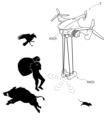
- the working aircraft 1 includes a monitoring device A3 as the working device 3 for performing monitoring work.
- the monitoring device A3 include, but are not limited to, a monitoring camera, an infrared sensor, a thermograph, a laser sensor, an ultrasonic sensor, and the like.
- the flying object 2 also includes a repelling device A4 as a working device 3 for repelling suspicious persons and birds and beasts.
- the repelling device A4 is not particularly limited as long as it can repel suspicious persons and birds and beasts, but examples include ultrasonic generators, sonic generators, light generators, stun guns, bitter, sour, pungent, and salty devices. Examples include devices that impart flavor.
- the work flying vehicle 1 itself may be used as the repelling device repelling device A4, such as by ramming the working flying vehicle 1.
- These monitoring work and repulsion work may be performed by a plurality of work aircraft 1 flying in a group, or may be performed cooperatively by a plurality of work aircraft 1 flying in their respective areas. It's okay.
- group monitoring or repelling work it is conceivable that, for example, the work aircraft 1 belonging to the area where the suspicious person or bird or beast has appeared, or the work aircraft 1 belonging to the neighboring area, perform the work in a group.
- the monitoring device A3 may perform individual recognition and, for example, intensively repel the boss of the group, or grasp behavioral trends of birds, beasts, and suspicious persons, and take appropriate repelling actions.
- the work aircraft may be equipped with a reporting device that provides notification based on the monitoring results of the monitoring device A3.
- the reporting device can send a report to, for example, a mobile terminal of a worker, a manager, a supervisor, or the like.
- the notification device may be used to notify a police station, fire department, hunter, or the like.
- the work aircraft may be equipped with a marking device that marks the monitoring target based on the monitoring results of the monitoring device A3.
- a marking device that marks the monitoring target based on the monitoring results of the monitoring device A3.
- a paint gun can be used as the marking device.
- the scarecrow may be configured with a working flying vehicle 1, and may be a multi-functional scarecrow that assists in monitoring, repelling, assisting the position accuracy of the satellite positioning device, and assisting the work of the main working machine.
- monitoring and repulsion history information can be shared, for example, on a regional management server, or communication between work flying vehicles 1 can be used to identify individuals, identify the status of bird and beast damage, predict crime, and improve effective results. You may also share strategies for repelling them.
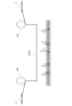
- the work aircraft 1 can be equipped with a work environment improvement device A5 as the work device 3 that improves the work environment in at least one of the work object and the surrounding area of the work object.
- the work environment improvement device A5 is a roof device that performs light shielding, heat shielding, rainproofing, etc. in the work area.
- This roof device includes a balloon 100 and a roof section formed of, for example, a canopy.
- Four balloons 100 are provided, for example, corresponding to each of the four corners of the roof, and are connected to the roof through wires.
- four flying objects 2 are connected to the wires of each balloon. This keeps the roof arrangement above the working area.
- This roof device improves the working environment by blocking light, heat shielding, rainproofing, etc.
- This roof device may be kept stationary in the sky, or may be moved to form a movable (following) roof device.
- a blower device that blows air for air conditioning such as cooling or air for an air curtain can be applied.
- the blower device may be stopped in the sky, or may be moved and used as a follow-up spot cooler.
- the work environment improvement device A5 may be a water or fragrance source spraying device or a relaxing sound or noise canceling sound generating device.
- work environment improvement device A5 is applicable not only to agricultural work in fields and forests, construction sites, and construction sites, but also to amusement parks, theme parks, sports facilities, and the like.
- the work aircraft 1 includes, as the work device 3, at least one of a material transport device that transports materials to another work device 3, and a harvest transport device that transports harvested products from the other work device 3. But that's fine.
- the material transport device that transports materials to other working devices 3 include a material transport device that transports seedlings, fertilizers, medicines, etc. to a rice transplanter.
- a harvest conveyance device which conveys a harvest from another working device 3 for example, a material conveyance device which conveys grain, which is a harvest from a combine harvester, to a rice cart.
- These working flying vehicles 1 for transporting materials and working flying vehicles 1 for transporting crops may be provided with dedicated flying vehicles, or the above-mentioned working flying vehicles 1 may also be used.
- the winch 51 may be attached to the flying object 2.
- the transmission section 35 may be configured to be able to send fuel to the engine.
- the transmission section 35 may be configured to be able to transmit heat or power. In this case, both heat and power correspond to "energy” according to the present invention.
- the work system SY may include a position prediction unit that predicts the position of the work device 3 when the flying object 2 is accelerating, decelerating, or turning.
- the flight control unit 31 may be configured to control the flight of the flying object 2 based on the prediction result by the position prediction unit.
- the position prediction unit calculates the positional deviation of the working device 3 with respect to the flying object 2. By doing so, the position of the working device 3 is predicted. Then, based on this prediction result, the flight control unit 31 controls the flight of the flying object 2 when turning so that the flying object 2 is located on the inside of the turning than the target trajectory of the working device 3 when turning.
- the main unit 42 may be configured to control the flight motor 22, winch 51, and work device 3 based on various information.
- the information may be, for example, information obtained by a mobile sensor or a fixed sensor located at the work site or around the work site.
- the mobile sensor may be, for example, a sensor provided in a self-propelled work machine.
- the fixed sensor may be, for example, a multi-functional scarecrow, a GPS base station, a surveillance camera, a sensor provided in a wildlife damage prevention fence, or the like.
- the information may be, for example, information obtained from smart machines linked to the supply chain.
- the main unit 42 acquires operating information of a grain dryer that is equipped with a harvesting device as the working device 3 and is configured as a smart machine linked to the supply chain, and based on the operating information, The main unit 42 may control the flight motor 22, the winch 51, and the work device 3 so that the harvest timing is optimal.
- a tilling rotor is provided as the working device 3, and the flight control unit 31 drives the flight motor 22 in the direction in which the flying object 2 descends, so that the working flying object 1 pushes the tilling rotor downward. It may also be configured to fly while As a result, it is possible to realize a work aircraft 1 that can perform plowing work equivalent to plowing work using a conventional work vehicle.
- flight control unit 31, relative position control unit 32, spatial position control unit 44, generation unit 46, acquisition unit 47, switching unit 48, and environment prediction unit 49 are external to the work aircraft 1.
- it may be provided in a management computer provided outside the work aircraft 1.
- the connection mechanism 5 may have the function of the transmission section 35.
- the transmission section 35 may or may not be provided.
- the connection mechanism 5 may transmit at least one of the energy and the electric signal instead of the transmission section 35 when a malfunction occurs in the transmission section 35 .
- the work aircraft 1 may be configured to cancel the operating sound of the propeller 21.
- the operations of the plurality of propellers 21 may be controlled so that their operating sounds cancel each other out.
- the work aircraft 1 may be provided with a muffling device that generates a sound (noise canceling sound) that cancels the operating sound of the propeller 21.
- the silencer may be configured to generate a noise canceling sound based on the control amount sent to the flight motor 22.
- connection structure between the winch 51 and the work device 3 is designed as a common standard for various types of work devices 3, and is configured so that various types of work devices 3 can be connected to the winch 51. You can leave it there.
- connection structure between the flying object 2 and the connecting mechanism 5 is designed as a common standard for various types of flying objects 2, and various types of flying objects 2 can be connected to the connecting mechanism 5. It may be configured as follows.
- the propeller 21 may be configured to be rotatable about a rotation axis of the propeller 21 that extends in the left-right direction of the aircraft. That is, the propeller 21 may be of a so-called tilt type. With this configuration, the work aircraft 1 is capable of vertical takeoff and landing, hovering flight, and high-speed horizontal flight.
- the work aircraft 1 or another aircraft may be provided with a work result acquisition unit that acquires the results of work performed by the work device 3. Based on the work results acquired by the work result acquisition unit, the work plan creation unit can create, for example, a work plan for subsequent processes or a work plan for the next year and thereafter. If this work plan is saved in the work plan storage section of the management server, it can be utilized for subsequent processes and work from the next year onward.
- the data generated by the generation unit 46 does not need to include information indicating time.
- the generation unit 46 generates target position data that is data indicating the target position of the flying object 2 or the work device 3 in the work space, and in this target position data, time is associated with the target position. You don't have to.
- this target position data may be the time-series target position data shown in FIG. 6 from which information indicating time has been deleted.
- the target position may be expressed, for example, as a combination of x-coordinate values, y-coordinate values, and z-coordinate values in a three-dimensional space, similarly to the above embodiment.
- the flight control unit 31 may be configured to control the flight of the flying object 2 based on this target position data.
- the environment prediction unit 49 may predict the work environment based on any information other than the information acquired from the sensing aircraft 37 or the event detection unit 38.
- the environment prediction unit 49 uses information obtained from some or all of fixed sensors, the Internet, sensors of work equipment 3, etc. in other work aircraft 1, and sensors of work machines such as tractors.
- the work environment may be predicted based on the information.
- the present invention can be used in a work system that includes a work device that can perform predetermined work.
Landscapes
- Engineering & Computer Science (AREA)
- Aviation & Aerospace Engineering (AREA)
- Automation & Control Theory (AREA)
- Control Of Position, Course, Altitude, Or Attitude Of Moving Bodies (AREA)
Abstract
【課題】種々の作業における飛行体の活用を図るに際して、適切に作業を行うことが可能な飛行体を提供する。 【解決手段】飛行体2と、所定の作業を実施可能な作業装置3と、作業装置3を制御する作業制御部とを備え、作業制御部が、作業装置3が作業対象位置に位置する場合に作業装置の駆動を許容し、且つ、作業装置3が作業対象位置に位置しない場合には作業装置の駆動を抑制する。
Description
本発明は、作業飛行体及び飛行体を用いて作業を行う作業システムに関する。
近年、ドローン等の飛行体を用いた農作業の効率化が検討されている。特許文献1には、農作業の一例として農薬などを散布する散布装置が搭載された飛行体の支援装置が開示されている。
種々の作業における飛行体の活用を図るに際して、適切に作業を行うことが可能な飛行体が要望されている。
本発明の作業飛行体は、飛行体と、所定の作業を実施可能な作業装置と、前記作業装置を制御する作業制御部とを備え、前記制御手段が、前記作業装置が作業対象位置に位置する場合に前記作業装置の駆動を許容し、且つ、前記作業装置が作業対象位置に位置しない場合には前記作業装置の駆動を抑制する。
本発明であれば、作業装置が作業対象位置に位置しない場合には、作業装置の駆動を抑制することができる。したがって、適切な作業対象位置に対して作業を行うことができる。
さらに、本発明において、前記作業制御部が、前記作業対象位置に対する作業を行う作業予定時間である場合に前記作業装置の駆動を許容し、且つ、前記作業予定時間でない場合には前記作業装置の駆動を抑制すると好適である。
作業によっては、適切な時期に行うことを要するものがある。そこで、この構成な構成にすることにより、作業予定時間でない場合には作業装置の駆動を抑制することができる。
さらに、本発明において、前記作業装置が、作業対象位置に位置しないことを報知する報知手段を備えると好適である。
さらに、本発明において、前記作業装置が、作業対象位置に位置する状態から作業対象位置に位置しない状態に変位する際に、前記作業制御部による前記作業装置の駆動の抑制に先立ち、前記報知手段による報知が行われると好適である。
さらに、本発明において、前記飛行体の飛行を制御する飛行制御部を備え、前記飛行制御部が、作業対象位置の周辺の環境状態及び環境状況の予測の少なくともいずれかに基づいて、予め設定された作業経路を変更すると好適である。
さらに、本発明において、前記環境状況が風向き及び風速の少なくともいずれか一方であると好適である。
さらに、本発明において、前記作業制御部が、作業対象の3次元形状に基づいて前記作業装置を制御すると好適である。
さらに、本発明において、前記飛行体の飛行を制御する飛行制御部を備え、前記飛行制御部が、作業対象の3次元形状に基づいて前記飛行体を制御すると好適である。
さらに、本発明において、前記作業装置が、耕耘装置、施薬装置、施肥装置、播種装置、苗移植装置、作物収穫装置、除雪装置のうちの少なくともいずれか一つを含むと好適である。
さらに、本発明において、前記作業装置が、作業対象及び作業対象の周辺領域のうちのすくなくともいずれかにおける作業環境を改善する作業環境改善装置を含むと好適である。
さらに、本発明において、前記作業装置が、作業対象及び作業対象の周辺領域のうちの少なくともいずれかを監視する監視装置を含み、前記監視装置の監視結果に基づいて監視対象を撃退する撃退装置を備えると好適である。
さらに、本発明において、前記作業装置が、作業対象及び作業対象の周辺領域のうちの少なくともいずれかを監視する監視装置を含み、前記監視装置の監視結果に基づいて通報を行う通報装置を備えると好適である。
さらに、本発明において、前記作業装置が、作業対象及び作業対象の周辺領域のうちの少なくともいずれかを監視する監視装置を含み、前記監視装置の監視結果に基づいて監視対象にマーキングを行うマーキング装置を備えると好適である。
さらに、本発明において、前記作業装置が、他の作業装置へ資材を搬送する資材搬送装置、及び、他の作業装置から収穫物を搬送する収穫物搬送装置の少なくともいずれかを含むと好適である。
本発明の作業システムは、飛行体を用いて作業を行う作業システムであって、飛行体と、所定の作業を実施可能な作業装置と、前記飛行体の位置及び前記作業装置の位置に関する情報である自機位置情報を取得する測位装置と、前記作業装置を制御する作業制御部と、作業計画情報を記憶する作業計画記憶部とを備え、前記作業計画情報には、作業対象位置情報が含まれており、前記作業制御部が、前記自機位置情報と前記作業対象位置情報とに基づいて、前記作業装置が作業対象位置に位置する場合に前記作業装置の駆動を許容し、且つ、前記作業装置が作業対象位置に位置しない場合には前記作業装置の駆動を抑制する。
本発明であれば、作業計画情報に含まれる作業対象位置情報に基づいて、作業装置が作業対象位置に位置しない場合には、作業装置の駆動を抑制することができる。したがって、適切な作業対象位置に対して作業を行うことができる。
さらに、本発明において、前記作業計画情報には、作業対象に対する作業を行う作業予定時間に関する作業予定時間情報が含まれ、前記作業制御部が、作業予定時間情報に基づき、前記作業予定時間である場合に前記作業装置の駆動を許容し、且つ、前記作業予定時間でない場合には前記作業装置の駆動を抑制すると好適である。
作業によっては、適切な時期に行うことを要するものがある。そこで、このような構成にすることにより、作業計画情報に含まれる作業対象に対する作業を行う作業予定時間に関する作業予定時間情報に基づいて、作業予定時間でない場合には作業装置の駆動を抑制することができる。
さらに、本発明において、前記作業予定時間情報は、作業予定時間内の各時点における前記飛行体及び前記作業装置の少なくともいずれかの作業空間内での目標位置を示す時系列目標位置データを含み、飛行制御部は、前記時系列目標位置データに基づいて前記飛行体の飛行を制御すると好適である。
この構成によれば、時系列目標位置データに基づいて、作業空間における作業を自動的に行うことができる。
前記作業装置による作業の結果を取得する作業結果取得部と、作業計画を作成する作業計画作成部とを備え、前記作業の結果に基づいて後の作業に関する作業計画を作成すると好適である。
本構成によれば、作業結果取得部が取得した作業の結果に関する情報に基づいて、作業計画作成部がのちの作業計画を好適に作成することができる。ここで、後の作業には、後工程の作業や次年度以降の作業が含まれ得る。
さらに、本発明において、作業対象位置の周辺の環境状況を予測する環境状況予測部を備え、環境状況予測部は、前記作業対象位置の周辺の環境状態を検知する環境状況検知装置を備えた検知飛行体により検知された環境状況に基づいて、環境状況を予測すると好適である。
本発明を実施するための形態について、図面に基づき説明する。尚、以下の説明においては、特に断りがない限り、図2、図7、図8に示す矢印Fの方向を「前」、矢印Bの方向を「後」として、図1、図2、図4、図7、図8に示す矢印Lの方向を「左」、矢印Rの方向を「右」とする。また、図1及び図4に示す矢印Uの方向を「上」、矢印Dの方向を「下」とする。
〔作業飛行体の全体構成〕
本実施形態における作業システムSY(図3参照)は、図1及び図2に示す作業飛行体1を備えている。
本実施形態における作業システムSY(図3参照)は、図1及び図2に示す作業飛行体1を備えている。
図1及び図2に示すように、作業飛行体1は、飛行体2と、作業装置3と、四つの接続機構5と、を備えている。
本実施形態において、飛行体2は、単独で飛行可能なマルチコプターである。図1及び図2に示すように、飛行体2は、本体部20、複数のプロペラ21、複数のアーム部25を有している。
本体部20は、平面視で円形状に構成されている。複数のアーム部25は、本体部20から、水平方向に、放射状に延びている。そして、各アーム部25の遊端部に、プロペラ21が取り付けられている。
尚、プロペラ21及びアーム部25の設けられる個数は特に限定されないが、本実施形態において、プロペラ21及びアーム部25は、それぞれ四つ設けられている。そして、四つのアーム部25は、それぞれ、本体部20から、左前方、右前方、左後方、右後方へ延びている。
各プロペラ21は、電動の飛行用モータ22(図3参照)の駆動力によって駆動する。
そして、飛行体2は、各プロペラ21を駆動することによって飛行可能である。
そして、飛行体2は、各プロペラ21を駆動することによって飛行可能である。
より具体的には、飛行体2は、各プロペラ21を駆動することにより、空中に浮かんだ状態で、上下方向、前後方向、左右方向の何れにも移動することが可能である。また、飛行体2は、各プロペラ21を駆動することにより、停止飛行が可能である。
尚、飛行体2は、作業飛行体1に組み込まれた状態でも、また、作業飛行体1から取り外された状態でも、飛行可能である。
図1及び図2に示す例において、作業装置3は、薬剤散布機A1である。薬剤散布機A1は、作物に対する薬剤散布作業(本発明に係る「所定の作業」に相当)を実施可能である。ただし、本発明はこれに限定されず、作業装置3は、作業を実施可能であれば、いかなる種類の装置であっても良い。また、作業装置3は、必要とされる作業に応じて、様々な種類の作業装置3に交換することができる。
即ち、作業システムSYは、所定の作業を実施可能な作業装置3を備えている。
図1及び図2に示すように、作業装置3は、四つの接続機構5を介して、飛行体2から吊り下げられている。各接続機構5は、例えば、公知のワイヤであっても良い。また、各接続機構5は、電動のウインチ51(本発明に係る「接続長さ変更部」に相当)から上側へ延びている。そして、各接続機構5の上端は、アーム部25の遊端部に接続している。
ウインチ51は、接続機構5を巻き取り及び繰り出し可能である。
ウインチ51は、接続機構5を巻き取り及び繰り出し可能である。
各ウインチ51は、作業装置3の上端部に取り付けられている。尚、各ウインチ51は、それぞれ、平面視において、作業装置3の左前部、右前部、左後部、右後部に取り付けられている。
このように、ウインチ51は、作業装置3に取り付けられている。
以上で説明した構成により、飛行体2は、接続機構5を介して作業装置3に接続されている。より具体的には、飛行体2は、複数の接続機構5を介して作業装置3に接続されている。
各ウインチ51が接続機構5を巻き取ることにより、飛行体2と作業装置3との間における接続機構5の長さが短くなる。これにより、作業装置3は飛行体2に近付く。その結果、作業装置3は上昇する。
各ウインチ51が接続機構5を繰り出すことにより、飛行体2と作業装置3との間における接続機構5の長さが長くなる。これにより、作業装置3は飛行体2から遠ざかる。その結果、作業装置3は下降する。
このように、作業システムSYは、飛行体2と作業装置3との間における接続機構5の長さを変更するウインチ51を備えている。
以上で説明した構成により、図1に示すように、作業装置3は、飛行体2に対して昇降可能である。
各プロペラ21を駆動することにより、飛行体2は、作業装置3と共に移動可能である。これにより、飛行装置1は、移動しながら、作業装置3によって所定の作業を実施できる。
即ち、作業システムSYは、作業装置3に接続されると共に、作業装置3を移動可能な飛行体2を備えている。
また、図1及び図2に示すように、飛行体2は、第1バッテリ26(本発明に係る「エネルギー源」に相当)を有している。第1バッテリ26は、電力(本発明に係る「エネルギー」に相当)を貯留可能である。また、第1バッテリ26は、飛行用モータ22及びウインチ51に電力を供給可能である。飛行用モータ22及びウインチ51は、第1バッテリ26から供給される電力により駆動可能である。
また、図1に示すように、作業装置3は、第2バッテリ30を有している。第2バッテリ30は、電力を貯留可能である。作業装置3は、第2バッテリ30の電力によって駆動可能である。
また、図1及び図2に示すように、飛行体2は、第1バッテリ26(を有している。第1バッテリ26は、電力(本発明に係る「エネルギー」に相当)を貯留可能である。また、第1バッテリ26は、飛行用モータ22及びウインチ51に電力を供給可能である。飛行用モータ22及びウインチ51は、第1バッテリ26から供給される電力により駆動可能である。
また、図1に示すように、作業装置3は、第2バッテリ30を有している。第2バッテリ30は、電力を貯留可能である。作業装置3は、第2バッテリ30の電力によって駆動可能である。
〔制御部について〕
図1に示すように、飛行体2は、メインユニット42を有している。メインユニット42は、特に限定されないが、例えば、本体部20に格納されていても良い。
図1に示すように、飛行体2は、メインユニット42を有している。メインユニット42は、特に限定されないが、例えば、本体部20に格納されていても良い。
メインユニット42は図3に示すように、制御部44を有している。制御部44は、作業空間における作業装置3の位置を制御するように構成されている。以下では、制御部44について詳述する。
図3に示すように、制御部44は、飛行制御部31及び相対位置制御部32を含んでいる。
このように、作業システムは、飛行制御部31及び相対位置制御部32を有する制御部44を備えている。即ち、作業システムは、飛行制御部31を有する制御部44を備えている。
飛行制御部31は、各飛行用モータ22を制御するように構成されている。これにより、飛行制御部31は、飛行体2の飛行を制御する。
即ち、作業システムは、飛行体2の飛行を制御する飛行制御部31を備えている。
また、制御部32は、各ウインチ51を制御するように構成されている。これにより、制御部32は、飛行体2と作業装置3との相対位置を制御する。
即ち、作業システムは、飛行体2と作業装置3との相対位置を制御する制御部32を備えている。
詳述すると、制御部32は、各ウインチ51が接続機構5を巻き取るように各ウインチ51を制御することにより、作業装置3を飛行体2に近付けることができる。また、制御部32は、各ウインチ51が接続機構5を繰り出すように各ウインチ51を制御することにより、作業装置3を飛行体2から遠ざけることができる。
また、制御部32は、飛行体2に対する作業装置3の姿勢を制御することが可能である。尚、飛行体2に対する作業装置3の姿勢は、飛行体2と作業装置3との相対位置に相当する。
詳述すると、制御部32は、図4に示すように、飛行装置1における右側の二本の接続機構5の長さが、飛行装置1における左側の二本の接続機構5よりも短くなるように、各ウインチ51を制御可能である。これにより、作業装置3は、飛行体2に対して傾いた姿勢となる。
このように、相対位置制御部32は、ウインチ51を制御することにより、飛行体2と作業装置3との相対位置を制御する。
この構成により、相対位置制御部32は、図4に示すように、地面の傾斜に合わせるように、作業装置3を傾けることができる。
また、以上で説明した構成により、制御部44は、飛行制御部31によって飛行体2の飛行を制御可能である。また、制御部44は、相対位置制御部32によって飛行体2と作業装置3との相対位置を制御可能である。そして、制御部44は、飛行体2の飛行の制御と、飛行体2と作業装置3との相対位置の制御と、を統合的に行うことにより、作業空間における作業装置3の位置を制御する。
即ち、制御部44は、飛行制御部31によって飛行体2の飛行を制御することにより、作業空間における作業装置3の位置を制御するように構成されている。より具体的には、制御部44は、飛行制御部31によって飛行体2の飛行を制御すると共に、相対位置制御部32によって飛行体2と作業装置3との相対位置を制御することにより、作業空間における作業装置3の位置を制御するように構成されている。
また、図3に示すように、メインユニット(42図1を参照)は、衛星測位装置45を有している。衛星測位装置45は、GPS(グローバル・ポジショニング・システム)で用いられる人工衛星からのGPS信号を受信する。そして、衛星測位装置45は、受信したGPS信号に基づいて、飛行装置1の位置座標を経時的に算出する。
尚、本発明はこれに限定されない。衛星測位装置45は、GPSを利用するものでなくても良い。例えば、衛星測位装置45は、GPS以外のGNSS(GLONASS、Galileo、みちびき、BeiDou等)を利用するものであっても良い。
算出された飛行装置1の経時的な位置座標は、空間位置制御部44へ送られる。
また、メインユニット42は、取得部47を有している。取得部47は、物体情報を取得する。尚、物体情報とは、作業空間における物体の位置及び高さを示す情報である。また、物体とは、例えば、地面、障害物、作物等である。つまり、作業対象の3次元形状に基づいて、作業飛行体1(飛行体2や作業装置3)の制御を行う。
このように、作業システムは、作業空間における物体の位置及び高さを示す情報である物体情報を取得する取得部47を備えている。
取得部47は、特に限定されないが、例えば、作業飛行体1の外部に設けられた管理サーバ(図示せず)から、物体情報を取得しても良い。また、例えば、取得部47は、トラクタやコンバイン等の作業車両から、物体情報を取得しても良い。また、例えば、取得部47は、作業飛行体1の周囲の物体の位置及び高さを検知する物体センサ(図示せず)を含むと共に、この物体センサによる検知結果に基づいて物体情報を生成することにより、物体情報を取得しても良い。また、管理サーバ(図示せず)が、作業計画情報を記憶する作業計画記憶部を備え、作業計画記憶部に含まれる作業対象位置情報に基づいて、物体情報を取得してもよい。
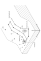
図5には、取得部47により取得された物体情報により示される内容の一例が示されている。図5に示す例では、物体情報により、三次元の作業空間における地面の起伏と、樹木TRの位置及び高さと、が示されている。
図5には、第1地点P1、第2地点P2、第3地点P3が示されている。物体情報により、例えば、第1地点P1、第2地点P2、第3地点P3の各地点における地面の位置及び高さが示される。
第1地点P1及び第2地点P2は、何れも、平坦な地面に位置している。また、第2地点P2は、第1地点P1よりも高い位置に位置している。また、第3地点P3は、傾斜地に位置している。そして、第3地点P3は、第2地点P2よりも低く、第1地点P1よりも高い位置に位置している。
図3に示すように、物体情報は、取得部47から生成部46へ送られる。生成部46は、取得部47から受け取った物体情報に基づいて、時系列目標位置データを生成する。時系列目標位置データとは、作業予定時間内の各時点における飛行体2または作業装置3の作業空間内での目標位置を示すデータである。
このように、作業システムは、作業予定時間内の各時点における飛行体2または作業装置3の作業空間内での目標位置を示す時系列目標位置データを生成する生成部46を備えている。
本実施形態における時系列目標位置データは、作業予定時間内の各時点における作業装置3の作業空間内での目標位置を示すデータである。
図6には、時系列目標位置データの一例が示されている。図6に示す例では、時刻t1から時刻t15までの各時点における、作業装置3の作業空間内での目標位置が示されている。図6に示す例では、時刻t1が作業開始時刻であり、時刻t15が作業終了時刻である。そして、時刻t1から時刻t15までの期間が、本発明に係る「作業予定時間」に相当する。
ここで、作業装置3の作業空間内での目標位置は、三次元空間における、x座標の値、y座標の値、z座標の値の組み合わせで表される。例えば、時刻t1における目標位置は、x座標の値がa1、y座標の値がb1、z座標の値がc1である位置である。また、時刻t2における目標位置は、x座標の値がa2、y座標の値がb2、z座標の値がc2である位置である。また、時刻t15における目標位置は、x座標の値がa15、y座標の値がb15、z座標の値がc15である位置である。
図5においては、図6に示す時系列目標位置データにより示される各目標位置がプロットされている。図5に示すように、各目標位置を時系列順で繋げた線が、作業装置3の目標移動経路LIとなる。生成部46は、目標移動経路LIを生成するように構成されていても良い。
尚、図5に示すように、生成部46は、物体情報に含まれる樹木TRの位置及び高さを示す情報に基づいて、飛行装置1が樹木TRを迂回するように、時刻t12における目標位置を決定する。
生成部46により生成された時系列目標位置データは、図3に示すように、制御部44へ送られる。
制御部44は、衛星測位装置45から受け取った飛行装置1の位置座標と、生成部46から受け取った時系列目標位置データと、に基づいて、作業空間における作業装置3の位置を制御する。
より具体的には、制御部44は、時系列目標位置データに従って作業装置3が移動するように、作業装置3の位置を制御する。このとき、飛行制御部31は、時系列目標位置データにより示される時刻において、その時刻に対応する目標位置に作業装置3が位置するように、飛行用モータ22を制御する。
例えば、図5及び図6に示す例では、飛行制御部31は、時刻t1において、時刻t1に対応する目標位置に作業装置3が位置するように、飛行用モータ22を制御する。また、飛行制御部31は、時刻t2において、時刻t2に対応する目標位置に作業装置3が位置するように、飛行用モータ22を制御する。
また、制御部32は、飛行制御部31による作業装置3の位置制御の誤差を補完するように、ウインチ51を制御する。
以上の構成により、作業装置3は、所定の作業を実施しながら、図5に示す目標移動経路LIに沿って移動することとなる。
即ち、飛行制御部31は、時系列目標位置データに基づいて飛行体2の飛行を制御する。
また、以上で説明した通り、時系列目標位置データは、取得部47により取得された物体情報に基づいて生成される。即ち、飛行制御部31は、取得部47により取得された物体情報に基づいて飛行体2の飛行を制御する。
尚、生成部46が目標移動経路LIを生成する場合は、目標移動経路LIは空間位置制御部44へ送られる。そして、空間位置制御部44は、作業装置3が目標移動経路LIに沿って移動するように、作業飛行体1を制御する。
本実施形態において、作業装置3は、駆動状態と、停止状態と、の間で状態変更可能である。ここで、駆動状態とは、駆動可能な状態である。また、停止状態とは、駆動しない状態である。
より具体的には、作業装置3は、電源オン状態と、電源オフ状態と、の間で状態変更可能である。電源オン状態は、駆動状態に相当する。電源オフ状態は、停止状態に相当する。
尚、本発明はこれに限定されない。例えば、作業装置3が、エンジン等の駆動源から動力を受け取ることによって駆動するように構成されており、作業装置3への動力伝達経路におけるクラッチが入状態と切状態との間で切替可能に構成されていても良い。この場合、クラッチが入状態である状態は、駆動状態に相当する。クラッチが切状態である状態は、停止状態に相当する。
このように、作業装置3は、駆動可能な状態である駆動状態と、駆動しない状態である停止状態と、の間で状態変更可能である。
本実施形態においては、作業装置3は、電源オン状態である間、駆動し続ける。即ち、薬剤散布機A1は、電源オン状態である間、薬剤を散布し続ける。しかしながら、本発明はこれに限定されず、作業装置3は、電源オン状態である間、所定の指示信号を受け取ったときに限り、駆動するように構成されていても良い。
図3に示すように、制御部44は、切替部48を有している。切替部48は、作業装置3の状態を、駆動状態と停止状態との間で切り替えることができる。より具体的には、切替部48は、作業装置制御部52に対して、作業装置3の状態を、電源オン状態と電源オフ状態との間で切り替える切替信号を出力する。
より具体的には、切替部48は、作業装置3が備える作業装置制御部52に電源をオンにする指令信号を送信して作業装置3を電源オン状態に切り替えて、作業装置3が備える作業装置制御部52に電源をオフにする指令信号を送信して作業装置3を電源オフ状態に切り替える。
本実施形態において、飛行制御部31による作業装置3の位置制御の誤差が所定の閾値を超えた場合、作業装置3の駆動が停止されるように構成されている。
即ち、制御部44は、衛星測位装置45から経時的に取得した作業飛行体の位置座標(本実施形態では平面位置に加えて高さ位置を含む3次元の位置情報)に関する情報と、時系列目標位置データとに基づいて、差が所定の閾値を超えた場合、切替部48は、作業装置3が備える作業装置制御部52に対して、作業装置3の駆動を停止するための指令信号つまり、作業装置3を電源オフ状態とするための指令信号を送信する。これにより、作業装置3の駆動が停止される。ここで、切替部48及び作業装置制御部は、本発明の「作業制御部」に相当する。
なお、上記では、作業制御部(切替部48及び作業装置制御部52)が、作業装置3を電源オフ状態とすることにより、作業装置3の駆動を停止する場合を例に説明したが、これに限られるものではない。作業装置3への動力伝達経路におけるクラッチが入状態と切状態との間で切替可能に構成されている場合、クラッチを切状態でとすることにより作業装置3の駆動を停止してもよい。
飛行体2は、報知装置70を備えている。報知装置70は、例えば、ブザー、報知用のランプ、音声情報を発生可能なスピーカー等により構成されている。上記の、作業装置3の駆動の停止が行われた際には、その旨が、報知装置70により、報知される。なお、報知装置70により、上記の作業装置3の駆動の停止に先立ち、作業装置3の駆動が停止される旨の報知を行ってもよい。この場合、例えば、報知装置70による報知を行った後に、所定時間の間に作業装置3の駆動を停止すべき条件が解消された場合には、作業装置3の駆動の停止を行わないように制御してもよい。報知装置70は、飛行体2に備えられたものに限らず、例えば作業装置30に備えられてもよく、作業者、監視者、管理者等が有する携帯端末やリモコン等に備えられてもよい。報知装置70は、ハードウエアとして備えあれてもよく、ソフトウエアとして備えられてもよく、これらの協同で備えられてもよい。
また、上記において、必ずしも作業装置3の駆動を停止する必要はなく、作業装置3の駆動を抑制することができればよい。作業装置3の駆動の抑制の例としては、上記の作業装置3の駆動の停止に加えて、例えば、作業装置3の駆動速度や駆動力等の駆動の程度を小さくすることや、作業装置3の駆動の停止や駆動の程度を小さくすることを促す旨の報知等があげられる。また、作業装置3が駆動していない状態において、作業装置3が駆動しない状態を維持することも上記の抑制に含まれる。なお、これらの報知は、上記の報知装置70を介して行ってもよい。
また、上記の制御において、実際の時刻と時系列目標位置とデータにおける目標時刻との関係を考慮して制御を行ってもよい。つまり、上記の制御に加えて、例えば、時系列目標位置データにおける目標時刻と実際の時刻とが所定の閾値以上になった場合にも上記の作業装置3の駆動を抑制する制御を行ってもよい。
なお、上記のような厳密な制御で作業装置3の抑制の制御を行うのではなく、例えば、作業対象の圃場、森林、建設現場、工事現場等を作業対象領域として設定しておき、設定された作業対象領域から外れた場合や作業対象領域から所定の閾値を超えて外れた場合に、上記の作業装置3の駆動を抑制する制御を行ってもよい。
また、現在時刻が作業予定時間外である場合や現在時刻が所定の閾値を超えて作業予定時間外である場合に上記の作業装置3の駆動を抑制する制御を行ってもよい。
なお、上記の作業情報記憶部に記憶される上業計画情報には、作業対象に対する作業を行う作業予定時間に関する作業予定時間情報を含むことができ、作業予定時間情報に基づいて、現在時刻が作業予定時間外である場合や現在時刻が所定の閾値を超えて作業予定時間外である場合に上記の作業装置3の駆動を抑制する制御を行ってもよい。
〔距離検知装置について〕
図1に示すように、飛行装置1は、距離検知装置34(本発明に係る「距離測定部」、「接近検知部」に相当)を備えている。距離検知装置34は、作業装置3と地面との間の距離を検知することにより、作業装置3と地面との間の距離を測定することができる。
図1に示すように、飛行装置1は、距離検知装置34(本発明に係る「距離測定部」、「接近検知部」に相当)を備えている。距離検知装置34は、作業装置3と地面との間の距離を検知することにより、作業装置3と地面との間の距離を測定することができる。
即ち、作業システムSYは、作業装置3と地面との間の距離を測定する距離検知装置34を備えている。
また、距離検知装置34は、作業装置3と作業対象との接近状態を検知することができる。例えば、作業装置3が薬剤散布機A1である場合、作業対象は作物である。
即ち、作業システムSYは、作業装置3と作業対象との接近状態を検知する距離検知装置34を備えている。
距離検知装置34は、例えば、カメラや、レーダーや、LiDAR(レーザーレーダー)等を利用して、作業装置3と地面との間の距離を測定すると共に、作業装置3と作業対象との接近状態を検知するように構成されていても良い。
図3に示すように、距離検知装置34により測定された作業装置3と地面との間の距離を示す情報は、距離検知装置34から相対位置制御部32へ送られる。相対位置制御部32は、この情報に基づいて、各ウインチ51を制御する。このとき、例えば、相対位置制御部32は、作業装置3と地面との間の距離が一定距離に維持されるように、各ウインチ51を制御する。
このように、相対位置制御部32は、距離検知装置34による測定結果に基づいてウインチ51を制御する。
〔伝達部について〕
図1に示すように、作業飛行体1は、伝達部35を備えている。伝達部35は、例えば、公知のケーブルであっても良い。伝達部35により、飛行体2と作業装置3とが接続されている。即ち、伝達部35は、飛行体2と作業装置3とに亘って設けられている。
図1に示すように、作業飛行体1は、伝達部35を備えている。伝達部35は、例えば、公知のケーブルであっても良い。伝達部35により、飛行体2と作業装置3とが接続されている。即ち、伝達部35は、飛行体2と作業装置3とに亘って設けられている。
また、伝達部35は、接続機構5とは異なる部材である。また、各接続機構5と伝達部35とは離間している。即ち、接続機構5と伝達部35とは各別に設けられている。
伝達部35は、電力及び電気信号を伝達可能に構成されている。ただし、本発明はこれに限定されず、伝達部35は、電力及び電気信号のうちの一方のみを伝達可能に構成されていても良い。
即ち、作業システムSYは、エネルギー及び電気信号の少なくとも一方を伝達可能な伝達部35を備えている。
例えば、第1バッテリ26は、伝達部35を介して、電力を第2バッテリ30へ供給可能であっても良い。また、第2バッテリ30は、伝達部35を介して、電力を第1バッテリ26へ供給可能であっても良い。また、切替部48は、伝達部35を介して、電気信号を作業装置3の作業装置制御部52へ送ることにより、作業装置3の状態を、電源オン状態と電源オフ状態との間で切り替えるように構成されていてもよい。
〔無線伝達部について〕
図1に示すように、作業飛行体1は、無線伝達部36を備えている。無線伝達部36は、第1部材36a及び第2部材36bを有している。第1部材36aは、飛行体2の本体部20に取り付けられている。第2部材36bは、作業装置3に取り付けられている。
図1に示すように、作業飛行体1は、無線伝達部36を備えている。無線伝達部36は、第1部材36a及び第2部材36bを有している。第1部材36aは、飛行体2の本体部20に取り付けられている。第2部材36bは、作業装置3に取り付けられている。
第1部材36a及び第2部材36bは、互いの間で、電力及び電気信号を無線接続により伝達可能に構成されている。これにより、無線伝達部36は、電力及び電気信号を、飛行体2と作業装置3との間で、無線接続により伝達可能である。ただし、本発明はこれに限定されず、無線伝達部36は、電力及び電気信号のうちの一方のみを伝達可能に構成されていても良い。
即ち、作業システムSYは、エネルギー及び電気信号の少なくとも一方を、飛行体2と作業装置3との間で、無線接続により伝達可能な無線伝達部36を備えている。
無線伝達部36は、例えば、公知の無線電力伝送技術を利用して電力を伝達可能に構成されていても良い。また、無線伝達部36は、公知の近距離無線通信技術を利用して電気信号を伝達可能に構成されていても良い。
例えば、第1バッテリ26は、無線伝達部36を介して、電力を第2バッテリ30へ供給可能であっても良い。また、第2バッテリ30は、無線伝達部36を介して、電力を第1バッテリ26へ供給可能であっても良い。また、切替部48は、無線伝達部36を介して、電気信号を作業装置3の作業装置制御部52へ送ることにより、作業装置3の状態を、電源オン状態と電源オフ状態との間で切り替えるように構成されていてもよい。
尚、伝達部35が設けられており、飛行体2と作業装置3との間で伝達する必要のあるエネルギー及び電気信号が伝達部35によって伝達される構成においては、無線伝達部36は設けられていなくても良い。
また、無線伝達部36が設けられており、飛行体2と作業装置3との間で伝達する必要のあるエネルギー及び電気信号が無線伝達部36によって伝達される構成においては、伝達部35は設けられていなくても良い。
〔環境予測部について〕
図3及び図9に示すように、作業システムSYは、検知飛行体37を備えている。検知飛行体37は、飛行体2と同じ機構により、飛行可能に構成されている。
図3及び図9に示すように、作業システムSYは、検知飛行体37を備えている。検知飛行体37は、飛行体2と同じ機構により、飛行可能に構成されている。
即ち、作業システムSYは、飛行可能な検知飛行体37を備えている。
検知飛行体37は、事象検知部38(本発明の環境状況検知装置に相当する)を有している。事象検知部38は、作業環境に関する事象を検知するように構成されている。本実施形態において、作業環境とは、より具体的には、気象である。即ち、事象検知部38は、気象に関する事象を検知するように構成されている。
このように、検知飛行体37は、作業環境に関する事象を検知する事象検知部38を有している。また、本実施形態において、作業環境は気象である。
事象検知部38は、雨や風を検知する。尚、雨及び風は、気象に関する事象の具体例である。
また、事象検知部38は、雨や風の有無だけではなく、雨や風の強さを検知可能に構成されていても良い。
図3に示すように、メインユニット42は、環境予測部49を有している。事象検知部38による検知結果は、例えば管理コンピュータ(図示せず)やインターネット回線等を介して、環境予測部49へ送られる。
環境予測部49は、事象検知部38による検知結果(環境状況)に基づいて、飛行装置1が作業を行う作業空間における、未来の作業環境(環境状況)を予測する。尚、環境予測部49により予測される未来の作業環境は、例えば、1時間後の作業環境であっても良いし、現在から日没までの作業環境の推移であっても良い。
このように、作業システムSYは、作業空間における作業環境を予測する環境予測部49を備えている。また、環境予測部49は、事象検知部38による検知結果に基づいて作業環境を予測する。
例えば、図9に示す例では、検知飛行体37は、第1圃場F1において飛行している。
また、飛行装置1は、第2圃場F2において飛行している。尚、第1圃場F1と第2圃場F2とは互いに離れているものとする。また、第1圃場F1は、第2圃場F2に対して西側に位置しているものとする。
また、飛行装置1は、第2圃場F2において飛行している。尚、第1圃場F1と第2圃場F2とは互いに離れているものとする。また、第1圃場F1は、第2圃場F2に対して西側に位置しているものとする。
この例では、第1圃場F1において雨が降っており、且つ、比較的強い風が吹いている。第2圃場F2においては、天気は晴れであり、無風の状態である。
このとき、事象検知部38により、雨及び風が検知される。そして、環境予測部49は、事象検知部38による検知結果に基づいて、例えば、第2圃場F2において1時間後に雨が降り出すと共に比較的強い風が吹くことを予測する。
図3に示すように、環境予測部49による予測結果は、飛行制御部31へ送られる。飛行制御部31は、環境予測部49による予測結果に基づいて飛行体2の飛行を制御する。
例えば、環境予測部49により作業環境の悪化が予測された場合、飛行制御部31は、飛行装置1を所定の退避場所へ退避させるように、飛行体2の飛行を制御するように構成されていても良い。
例えば、環境予測部49により作業環境の悪化が予測された場合、飛行制御部31は、飛行装置1を所定の退避場所へ退避させるように、飛行体2の飛行を制御するように構成されていても良い。
また、環境予測部49による予測結果(環境状況の予測)に基づいて、飛行制御部31が、予め設定された作業経路を変更するようにしてもよい。例えば、環境予測部49による風向き及び風速に基づいて、飛行制御部31が、予め設定された目標移動経路LI(作業経路)を、風上側にオフセットするように変更してもよい。この際、風速に基づいて、散布された薬剤が風によって風下に流される程度を考慮して、風速が大きくなるほどオフセット量が大きくなるように、オフセット値を設定してもよい。
また、作業飛行体1に事象検知部38を設けて、雨及び風等の環境状況を検出し、この環境状況に基づいて、上記の目標移動経路LIのオフセットを行ってもよい。
〔その他の作業装置について〕
上記の作業飛行体1は、作業装置3として、薬剤散布装置A1を備える場合を例に説明したが、作業装置3は、これに限られるものではない。例えば図8に示すように、作業装置3として、除雪装置A2を備えてもよい。この際、除雪装置A2が、融雪剤を散布する散布装置を備えてもよい。なお、この飛行体2は、二つの主翼21aおよび一つの尾翼21bを有する。この二つ主翼21aは、ティルト可能であり、主翼21aをティルトさせて主翼21aの姿勢を変更することにより、垂直着陸飛行、ホバリング飛行、高速飛行等の飛行が可能である。例えば、住宅の屋根など建築物における除雪作業を行う場合は、例えば、設計図等の3次元データに基づいて、飛行チア2及び除雪装置A2を制御するとよい。
上記の作業飛行体1は、作業装置3として、薬剤散布装置A1を備える場合を例に説明したが、作業装置3は、これに限られるものではない。例えば図8に示すように、作業装置3として、除雪装置A2を備えてもよい。この際、除雪装置A2が、融雪剤を散布する散布装置を備えてもよい。なお、この飛行体2は、二つの主翼21aおよび一つの尾翼21bを有する。この二つ主翼21aは、ティルト可能であり、主翼21aをティルトさせて主翼21aの姿勢を変更することにより、垂直着陸飛行、ホバリング飛行、高速飛行等の飛行が可能である。例えば、住宅の屋根など建築物における除雪作業を行う場合は、例えば、設計図等の3次元データに基づいて、飛行チア2及び除雪装置A2を制御するとよい。
また、上記以外に、作業装置3として、耕耘装置、施薬装置、施肥装置、播種装置、苗移植装置、作物収穫装置等を備えてもよい。また、複数の作業装置3を備えてもよい。
耕耘装置としては、例えば、一般的なプラウやロータリーを用いることができる。また、ドリルにより圃場を掘り起こすことにより耕耘を行ってもよい。また、火薬、ミミズ、虫、モグラ等の耕耘作用のある散布物を散布してもよい。
苗移植装置としては、従来の苗植付装置を適用することができるほか、苗を投てきする装置であってもよい。
また、上記の作業装置をバルーン等の浮力確保体をアンカー等で、固定して、浮力確保体相対移動可能に支持してもよい。
上記の作業飛行体1は、屋上壁面緑化にも好適に活用できる。また、上記の作業飛行体は、水上、軟弱地ハウス内狭小地、山腹、がけ等においても好適に用いることができる。
また、工事現場や建設現場等においても用いることができる。
また、工事現場や建設現場等においても用いることができる。
また、図9に示す例では、作業飛行体1は、作業装置3として、監視作業を行うための監視装置A3を備える。監視装置A3としては、特に限定はされないが、例えば、監視カメラ、赤外線センサ、サーモグラフ、レーザーセンサ、超音波センサ等があげられる。また、この飛行体2は、作業装置3として、不審者や鳥獣の撃退作業を行う撃退装置A4を備える。撃退装置A4としては、不審者や鳥獣を撃退可能なものであれば特に限定はされないが、例えば、超音波発生装置、音波発生装置、光発生装置、スタンガン、苦み、酸味辛味、濃い塩味等の味を付与する装置等があげられる。また、作業飛行体1で体当たりする等、作業飛行体1自体を撃退装置撃退装置A4としてもよい。
これらの監視作業や撃退作業は、複数の作業飛行体1が集団で群飛行することによって、行ってもよく、複数の作業飛行体1がそれぞれの担当領域を飛行することにより、協同して行ってもよい。このような集団での監視作業や撃退作業を行うに際し、例えば、不審者や鳥獣が出現した地域に属する作業飛行体1やその近隣地期に属する作業飛行体が集団で行うことが考えられる。
また、監視装置A3が、個体認識を行い、例えば、集団のボスを集中的に撃退したり、鳥獣や不審者の行動傾向を把握して、適切な撃退行動をとってもよい。
また、作業飛行体は、監視装置A3の監視結果に基づいて通報を行う通報装置を備えてもよい。ここで通報装置は、例えば、作業者、管理者、監視者等の携帯端末に通報を行うことができる。また通報装置により、警察署や消防署やハンター等に通報を行ってもよい。
作業飛行体は、監視装置A3の監視結果に基づいて記監視装置の監視結果に基づいて監視対象にマーキングを行うマーキング装置を備えてもよい。マーキング装置としては、例えば、ペイント銃を適用することができる。
また、かかしを作業飛行体1で構成し、監視、撃退、衛星測位装置の位置精度の補助、主たる作業機の作業を補助する多機能かかしとしてもよい。
また、上記の監視、撃退の履歴情報を、例えば地域の管理サーバー等で共有したり、作業飛行体1同士で通信を行うなどして、個体認識、鳥獣害の状況、犯罪予測、効果的な撃退法等を共有してもよい。
また、作業飛行体1は、作業装置3として、作業対象及び作業対象の周辺領域のうちのすくなくともいずれかにおける作業環境を改善する作業環境改善装置A5を備えることができる。図10の例では、作業飛行体1は、作業環境改善装置A5は、作業領域における遮光、遮熱、防雨等を行う屋根装置である。この屋根装置は、例えば幌等により構成された屋根部とバルーン100を備える。バルーン100は、例えば屋根部の四隅のそれぞれに対応して4つ設けられ、ワイヤを介して屋根部に接続されている。また、それぞれのバルーンのワイヤに対応して4つの飛行体2が接続されている。これにより、作業領域の上方に屋根装置が保持されている。この屋根装置により、遮光、遮熱、防雨等を行うことにより作業環境が改善される。この屋根装置は、上空に停止させておいてもよいし、移動させて可動(追従)屋根装置としてもよい。
作業環境改善装置A5としては、冷却用などのエアコンディショニング用の空気やエアカーテン用の送風を行う送風装置を適用することができる。送風装置は、上空に停止させておいてもよいし、移動させて、追従スポットクーラーとして利用してもよい。
また、作業環境改善装置A5としては、水や香り源の散布装置やリラックス音やノイズキャンセル音の発生装置であってもよい。
なお、作業環境改善装置A5は、圃場や山林などにおける農作業、工事現場や建設現場のみならず、遊園地、テーマパーク、スポーツ施設、等においても適用可能である。
また、作業飛行体1が、作業装置3として、他の作業装置3へ資材を搬送する資材搬送装置、及び、他の作業装置3から収穫物を搬送する収穫物搬送装置の少なくともいずれかを含んでもよい。他の作業装置3へ資材を搬送する資材搬送装置としては、例えば、田植機に苗、肥料、薬剤等を搬送する資材搬送装置があげられる。また、他の作業装置3から収穫物を搬送する収穫物搬送装置としては、例えば、コンバインから収穫物である穀粒を籾車に搬送する資材搬送装置があげられる。これらの、資材搬送用の作業飛行体1や収穫物搬送用の作業飛行体1は、専用の飛行体を設けてもよいし、上記の作業飛行体1で兼用してもよい。
〔その他の実施形態〕
(1)ウインチ51は、飛行体2に取り付けられていても良い。
(1)ウインチ51は、飛行体2に取り付けられていても良い。
(2)作業飛行体1が、燃料により駆動するエンジンを備えている場合、伝達部35は、燃料をエンジンへ送ることができるように構成されていても良い。
(3)伝達部35は、熱または動力を伝達可能に構成されていても良い。この場合、熱及び動力は、何れも、本発明に係る「エネルギー」に相当する。
(4)作業システムSYは、飛行体2の加速時、減速時、旋回時の少なくとも何れかにおける作業装置3の位置を予測する位置予測部を備えていても良い。この場合、飛行制御部31は、この位置予測部による予測結果に基づいて飛行体2の飛行を制御するように構成されていても良い。
例えば、飛行体2の旋回によって、平面視における作業装置3の位置が、飛行体2の位置に対して旋回外側にずれる場合、位置予測部は、飛行体2に対する作業装置3の位置ずれを計算することにより、作業装置3の位置を予測する。そして、この予測結果に基づいて、飛行制御部31は、作業装置3の旋回時の目標軌跡よりも飛行体2が旋回内側に位置するように、飛行体2の旋回時の飛行を制御する。
(5)メインユニット42は、種々の情報に基づいて、飛行用モータ22、ウインチ51、作業装置3を制御するように構成されていても良い。当該情報は、例えば、作業対象地あるいは作業対象地の周辺に位置する移動式のセンサや固定式のセンサにより得られる情報であっても良い。この場合、移動式のセンサは、例えば、自走可能な作業機に備わるセンサであっても良い。また、固定式のセンサは、例えば、多機能かかし、GPS基地局、監視カメラ、鳥獣害防止柵に備わるセンサ等であっても良い。
また、当該情報は、例えば、サプライチェーンに紐づくスマート機械から得られた情報であっても良い。この場合、例えば、作業装置3として収穫装置が備えられ、サプライチェーンに紐づくスマート機械として構成された穀物乾燥機の稼働情報をメインユニット42が取得すると共に、当該稼働情報に基づいて、穀物の収穫タイミングが最適となるように、メインユニット42が飛行用モータ22、ウインチ51、作業装置3を制御しても良い。
(6)作業装置3として耕耘ロータが備えられると共に、飛行制御部31が、飛行体2が下降する方向に飛行用モータ22を駆動することにより、作業飛行体1が耕耘ロータを下側へ押し付けながら飛行するように構成されていても良い。これにより、従来の作業車両を利用した耕耘作業と同等の耕耘作業を実施可能な作業飛行体1を実現できる。
(7)飛行制御部31、相対位置制御部32、空間位置制御部44、生成部46、取得部47、切替部48、環境予測部49のうち、一部または全てが作業飛行体1の外部に備えられていても良いのであって、例えば、作業飛行体1の外部に設けられた管理コンピュータに備えられていても良い。
(8)接続機構5が、伝達部35の機能を有していても良い。この場合、伝達部35は設けられていても良いし、設けられていなくても良い。伝達部35が設けられる場合、伝達部35に不具合が生じた際に、伝達部35の代わりに、接続機構5がエネルギー及び電気信号の少なくとも一方を伝達しても良い。
(9)作業飛行体1が、プロペラ21の作動音を打ち消すよう構成されてもよい。例えば、複数のプロペラ21が、互いに作動音を打ち消すように動作制御されてもよい。例えば、プロペラ21の作動音を打ち消す音(ノイズキャンセル音)を発生する消音装置が作業飛行体1に設けられてもよい。その消音装置が、飛行用モータ22へ送られる制御量に基づいてノイズキャンセル音を生成するように構成されてもよい。
(10)作業飛行体1を構成する各要素が、様々な形態の作業飛行体1の間で流用可能なように設計されてもよい。例えば、ウインチ51と作業装置3との間の接続構造が、様々な種類の作業装置3における共通規格として設計されており、様々な種類の作業装置3をウインチ51に接続可能なように構成されていても良い。また、例えば、飛行体2と接続機構5との間の接続構造が、様々な種類の飛行体2における共通規格として設計されており、様々な種類の飛行体2を接続機構5に接続可能なように構成されていても良い。
(11)プロペラ21は、プロペラ21の回転軸を機体左右方向に延びる軸芯周りに回転可能なように構成されていても良い。即ち、プロペラ21は所謂ティルト式であっても良い。この構成であれば、作業飛行体1は、垂直離着陸、ホバリング飛行、及び高速水平飛行が可能である。
(12)作業飛行体1や別の飛行体に、作業装置3による作業の結果を取得する作業結果取得部を備えてもよい。作業結果取得部が取得した作業の結果に基づいて、作業計画作成部が、例えば後工程の作業計画や次年度以降の作業計画を作成することができる。この作業計画を管理サーバの作業計画記憶部に保存しておけば、後工程や次年度以降の作業に活用することができる。
(13)生成部46により生成されるデータに、時刻を示す情報が含まれていなくても良い。言い換えれば、生成部46は、飛行体2または作業装置3の作業空間内での目標位置を示すデータである目標位置データを生成すると共に、この目標位置データにおいて、目標位置に時刻が対応付けられていなくても良い。例えば、この目標位置データは、図6に示した時系列目標位置データから、時刻を示す情報が削除されたものであっても良い。また、この目標位置データにおいて、目標位置は、例えば、上記実施形態と同様に、三次元空間における、x座標の値、y座標の値、z座標の値の組み合わせで表されても良い。また、飛行制御部31は、この目標位置データに基づいて飛行体2の飛行を制御するように構成されていても良い。
(14)環境予測部49は、検知飛行体37または事象検知部38から取得する情報に限らず、いかなる情報に基づいて作業環境を予測しても良い。例えば、環境予測部49は、固定式のセンサ、インターネット、他の作業飛行体1における作業装置3等の持つセンサ、トラクタ等の作業機の持つセンサのうちの一部または全てから得られる情報に基づいて作業環境を予測するように構成されていても良い。
尚、上述の実施形態(別実施形態を含む、以下同じ)で開示される構成は、矛盾が生じない限り、他の実施形態で開示される構成と組み合わせて適用することが可能である。また、本明細書において開示された実施形態は例示であって、本発明の実施形態はこれに限定されず、本発明の目的を逸脱しない範囲内で適宜改変することが可能である。
本発明は、所定の作業を実施可能な作業装置を備える作業システムに利用可能である。
1 作業飛行体
2 飛行体
3 作業装置
37 検知飛行体
38 事象検知部(環境状態検知装置)
46 生成部
47 取得部
48 切替部(作業制御部)
49 環境予測部
52 作業装置制御部
2 飛行体
3 作業装置
37 検知飛行体
38 事象検知部(環境状態検知装置)
46 生成部
47 取得部
48 切替部(作業制御部)
49 環境予測部
52 作業装置制御部
Claims (19)
- 飛行体と、
所定の作業を実施可能な作業装置と、
前記作業装置を制御する作業制御部とを備え、
前記作業制御部が、前記作業装置が作業対象位置に位置する場合に前記作業装置の駆動を許容し、且つ、前記作業装置が作業対象位置に位置しない場合には前記作業装置の駆動を抑制する作業飛行体。 - 前記作業制御部が、前記作業対象位置に対する作業を行う作業予定時間である場合に前記作業装置の駆動を許容し、且つ、前記作業予定時間でない場合には前記作業装置の駆動を抑制する請求項1に記載の作業飛行体。
- 前記作業装置が、作業対象位置に位置しないことを報知する報知手段を備える請求項1又は2に記載の作業飛行体。
- 前記作業装置が、作業対象位置に位置する状態から作業対象位置に位置しない状態に変位する際に、前記作業制御部による前記作業装置の駆動の抑制に先立ち、前記報知手段による報知が行われる請求項3に記載の作業飛行体。
- 前記飛行体の飛行を制御する飛行制御部を備え、
前記飛行制御部が、作業対象位置の周辺の環境状態及び環境状況の予測の少なくともいずれかに基づいて、予め設定された作業経路を変更する請求項1~4のいずれか1項に記載の作業飛行体。 - 前記環境状況が風向き及び風速の少なくともいずれか一方である請求項5に記載の作業飛行体。
- 前記作業制御部が、作業対象の3次元形状に基づいて前記作業装置を制御する請求項1~6のいずれか1項に記載の作業飛行体。
- 前記飛行体の飛行を制御する飛行制御部を備え、
前記飛行制御部が、作業対象の3次元形状に基づいて前記飛行体を制御する請求項1~7のいずれか1項に記載の作業飛行体。 - 前記作業装置が、耕耘装置、施薬装置、施肥装置、播種装置、苗移植装置、作物収穫装置、除雪装置のうちの少なくともいずれか一つを含む請求項1~8のいずれか1項に記載の作業飛行体。
- 前記作業装置が、作業対象及び作業対象の周辺領域のうちのすくなくともいずれかにおける作業環境を改善する作業環境改善装置を含む請求項1~9のいずれか1項に記載の作業飛行体。
- 前記作業装置が、作業対象及び作業対象の周辺領域のうちの少なくともいずれかを監視する監視装置を含み、前記監視装置の監視結果に基づいて監視対象を撃退する撃退装置を備える請求項1~10のいずれか1項に記載の作業飛行体。
- 前記作業装置が、作業対象及び作業対象の周辺領域のうちの少なくともいずれかを監視する監視装置を含み、前記監視装置の監視結果に基づいて通報を行う通報装置を備える請求項1~11のいずれか1項に記載の作業飛行体。
- 前記作業装置が、作業対象及び作業対象の周辺領域のうちの少なくともいずれかを監視する監視装置を含み、前記監視装置の監視結果に基づいて監視対象にマーキングを行うマーキング装置を備える請求項1~12のいずれか1項に記載の作業飛行体。
- 前記作業装置が、他の作業装置へ資材を搬送する資材搬送装置、及び、他の作業装置から収穫物を搬送する収穫物搬送装置の少なくともいずれかを含む請求項1~13のいずれか1項に記載の作業飛行体。
- 飛行体を用いて作業を行う作業システムであって、
飛行体と、
所定の作業を実施可能な作業装置と、
前記飛行体の位置及び前記作業装置の位置に関する情報である自機位置情報を取得する測位装置と、
前記作業装置を制御する作業制御部と、
作業計画情報を記憶する作業計画記憶部とを備え、
前記作業計画情報には、作業対象位置情報が含まれており、前記作業制御部が、前記自機位置情報と前記作業対象位置情報とに基づいて、前記作業装置が作業対象位置に位置する場合に前記作業装置の駆動を許容し、且つ、前記作業装置が作業対象位置に位置しない場合には前記作業装置の駆動を抑制する作業システム。 - 前記作業計画情報には、作業対象に対する作業を行う作業予定時間に関する作業予定時間情報が含まれ、
前記作業制御部が、作業予定時間情報に基づき、前記作業予定時間である場合に前記作業装置の駆動を許容し、且つ、前記作業予定時間でない場合には前記作業装置の駆動を抑制する請求項15に記載の作業システム。 - 前記作業予定時間情報は、作業予定時間内の各時点における前記飛行体及び前記作業装置の少なくともいずれかの作業空間内での目標位置を示す時系列目標位置データを含み、
飛行制御部は、前記時系列目標位置データに基づいて前記飛行体の飛行を制御する請求項16に記載の作業システム。 - 前記作業装置による作業の結果を取得する作業結果取得部と、
作業計画を作成する作業計画作成部とを備え、
前記作業の結果に基づいて後の作業に関する作業計画を作成する請求項15~17のいずれか一項に記載の作業システム。 - 作業対象位置の周辺の環境状況を予測する環境状況予測部を備え、
環境情報予測部は、前記作業対象位置の周辺の環境状況を検知する環境状況検知装置を備えた検知飛行体により検知された環境状況に基づいて、環境状況を予測する請求項15~18のいずれか1項に記載の作業システム。
Priority Applications (1)
| Application Number | Priority Date | Filing Date | Title |
|---|---|---|---|
| PCT/JP2022/018265 WO2023203668A1 (ja) | 2022-04-20 | 2022-04-20 | 作業飛行体 |
Applications Claiming Priority (1)
| Application Number | Priority Date | Filing Date | Title |
|---|---|---|---|
| PCT/JP2022/018265 WO2023203668A1 (ja) | 2022-04-20 | 2022-04-20 | 作業飛行体 |
Publications (1)
| Publication Number | Publication Date |
|---|---|
| WO2023203668A1 true WO2023203668A1 (ja) | 2023-10-26 |
Family
ID=88419587
Family Applications (1)
| Application Number | Title | Priority Date | Filing Date |
|---|---|---|---|
| PCT/JP2022/018265 WO2023203668A1 (ja) | 2022-04-20 | 2022-04-20 | 作業飛行体 |
Country Status (1)
| Country | Link |
|---|---|
| WO (1) | WO2023203668A1 (ja) |
Citations (8)
| Publication number | Priority date | Publication date | Assignee | Title |
|---|---|---|---|---|
| JP2014177162A (ja) * | 2013-03-14 | 2014-09-25 | Secom Co Ltd | 撮影システム |
| JP2016173738A (ja) * | 2015-03-17 | 2016-09-29 | セコム株式会社 | 飛行ロボット制御システム及び飛行ロボット |
| JP2018511245A (ja) * | 2015-03-31 | 2018-04-19 | エスゼット ディージェイアイ テクノロジー カンパニー リミテッドSz Dji Technology Co.,Ltd | Uav搭載物制御システム |
| US20180357909A1 (en) * | 2015-12-09 | 2018-12-13 | Dronesense Llc | Drone Flight Operations |
| WO2020111096A1 (ja) * | 2018-11-27 | 2020-06-04 | 株式会社ナイルワークス | 作業計画装置、作業計画装置の制御方法、および、その制御プログラム、ならびにドローン |
| JP6747618B1 (ja) * | 2020-06-09 | 2020-08-26 | 東洋製罐株式会社 | 情報管理方法および情報管理システム |
| WO2021015277A1 (ja) * | 2019-07-23 | 2021-01-28 | 東洋製罐株式会社 | 吐出システム、吐出装置、無人航空機、操縦システムおよびエアゾール容器 |
| WO2021074968A1 (ja) * | 2019-10-15 | 2021-04-22 | 楽天株式会社 | 飛行体 |
-
2022
- 2022-04-20 WO PCT/JP2022/018265 patent/WO2023203668A1/ja unknown
Patent Citations (8)
| Publication number | Priority date | Publication date | Assignee | Title |
|---|---|---|---|---|
| JP2014177162A (ja) * | 2013-03-14 | 2014-09-25 | Secom Co Ltd | 撮影システム |
| JP2016173738A (ja) * | 2015-03-17 | 2016-09-29 | セコム株式会社 | 飛行ロボット制御システム及び飛行ロボット |
| JP2018511245A (ja) * | 2015-03-31 | 2018-04-19 | エスゼット ディージェイアイ テクノロジー カンパニー リミテッドSz Dji Technology Co.,Ltd | Uav搭載物制御システム |
| US20180357909A1 (en) * | 2015-12-09 | 2018-12-13 | Dronesense Llc | Drone Flight Operations |
| WO2020111096A1 (ja) * | 2018-11-27 | 2020-06-04 | 株式会社ナイルワークス | 作業計画装置、作業計画装置の制御方法、および、その制御プログラム、ならびにドローン |
| WO2021015277A1 (ja) * | 2019-07-23 | 2021-01-28 | 東洋製罐株式会社 | 吐出システム、吐出装置、無人航空機、操縦システムおよびエアゾール容器 |
| WO2021074968A1 (ja) * | 2019-10-15 | 2021-04-22 | 楽天株式会社 | 飛行体 |
| JP6747618B1 (ja) * | 2020-06-09 | 2020-08-26 | 東洋製罐株式会社 | 情報管理方法および情報管理システム |
Similar Documents
| Publication | Publication Date | Title |
|---|---|---|
| US11117663B2 (en) | Apparatus and method for unmanned flight | |
| US10577103B2 (en) | Systems and methods for dispensing an insecticide via unmanned vehicles to defend a crop-containing area against pests | |
| US20180074518A1 (en) | Apparatus and method for unmanned flight task optimization | |
| US20150127209A1 (en) | Bird repellent system | |
| US20180074499A1 (en) | Apparatus and method for monitoring a field | |
| KR101142737B1 (ko) | 조류 대응 시스템 | |
| US11147257B2 (en) | Software process for tending crops using a UAV | |
| US20190110461A1 (en) | Method and apparatus for identifying, locating and scaring away birds | |
| WO2018048666A1 (en) | Systems and methods for defending crops from crop-damaging pests via unmanned vehicles | |
| US20180068165A1 (en) | Systems and methods for identifying pests in crop-containing areas via unmanned vehicles based on crop damage detection | |
| US20180068164A1 (en) | Systems and methods for identifying pests in crop-containing areas via unmanned vehicles | |
| EP4149836A1 (en) | Obstacle monitoring systems and methods for same | |
| US20190152595A1 (en) | Apparatus for Sustained Surveillance and Deterrence with Unmanned Aerial Vehicles (UAV) | |
| US20200201332A1 (en) | Surveillance system for a wind park, and associated method | |
| KR102200384B1 (ko) | 유해 조류 퇴치 시스템 | |
| WO2023203668A1 (ja) | 作業飛行体 | |
| CN116569910A (zh) | 一种飞行驱鸟系统及驱鸟方法 | |
| AU2020202481B2 (en) | Pest control assembly, system and method | |
| WO2023203670A1 (ja) | 作業システム | |
| WO2023203667A1 (ja) | 飛行体及び飛行体による作業アシストシステム | |
| US20210243565A1 (en) | Object tracking systems and methods | |
| WO2023203673A1 (ja) | 飛行体制御システムおよび飛行体システム | |
| JP2019158540A (ja) | 情報提供システム、位置送信装置、情報収集装置及び情報提供装置 | |
| Grünkorn et al. | Behavioural Observations of White-Tailed Sea Eagles in the Vicinity of Wind Turbines | |
| CA2985600A1 (en) | Apparatus for sustained surveillance and deterrence with unmanned aerial vehicles (uav) |
Legal Events
| Date | Code | Title | Description |
|---|---|---|---|
| 121 | Ep: the epo has been informed by wipo that ep was designated in this application |
Ref document number: 22938471 Country of ref document: EP Kind code of ref document: A1 |