WO2023203668A1 - Véhicule aérien d'exécution de travail - Google Patents
Véhicule aérien d'exécution de travail Download PDFInfo
- Publication number
- WO2023203668A1 WO2023203668A1 PCT/JP2022/018265 JP2022018265W WO2023203668A1 WO 2023203668 A1 WO2023203668 A1 WO 2023203668A1 JP 2022018265 W JP2022018265 W JP 2022018265W WO 2023203668 A1 WO2023203668 A1 WO 2023203668A1
- Authority
- WO
- WIPO (PCT)
- Prior art keywords
- work
- target position
- control unit
- working
- aircraft
- Prior art date
Links
- RZVHIXYEVGDQDX-UHFFFAOYSA-N 9,10-anthraquinone Chemical group C1=CC=C2C(=O)C3=CC=CC=C3C(=O)C2=C1 RZVHIXYEVGDQDX-UHFFFAOYSA-N 0.000 claims description 36
- 238000001514 detection method Methods 0.000 claims description 36
- 230000007613 environmental effect Effects 0.000 claims description 28
- 238000012544 monitoring process Methods 0.000 claims description 19
- 238000012806 monitoring device Methods 0.000 claims description 17
- 239000000463 material Substances 0.000 claims description 12
- 230000032258 transport Effects 0.000 claims description 12
- 238000003306 harvesting Methods 0.000 claims description 11
- 230000001846 repelling effect Effects 0.000 claims description 11
- 239000000126 substance Substances 0.000 claims description 10
- 230000006872 improvement Effects 0.000 claims description 7
- 230000004720 fertilization Effects 0.000 claims description 3
- 238000010899 nucleation Methods 0.000 claims description 3
- 238000003971 tillage Methods 0.000 claims description 3
- 230000005540 biological transmission Effects 0.000 description 41
- 230000007246 mechanism Effects 0.000 description 25
- 230000008859 change Effects 0.000 description 7
- 230000033001 locomotion Effects 0.000 description 7
- 238000005507 spraying Methods 0.000 description 7
- 238000010276 construction Methods 0.000 description 6
- 238000013459 approach Methods 0.000 description 4
- 238000010586 diagram Methods 0.000 description 3
- 238000000034 method Methods 0.000 description 3
- 239000007921 spray Substances 0.000 description 3
- 241000209094 Oryza Species 0.000 description 2
- 235000007164 Oryza sativa Nutrition 0.000 description 2
- 235000013339 cereals Nutrition 0.000 description 2
- 238000004891 communication Methods 0.000 description 2
- 239000003814 drug Substances 0.000 description 2
- 230000000694 effects Effects 0.000 description 2
- 238000005516 engineering process Methods 0.000 description 2
- 239000000446 fuel Substances 0.000 description 2
- 238000005259 measurement Methods 0.000 description 2
- 230000008569 process Effects 0.000 description 2
- 235000009566 rice Nutrition 0.000 description 2
- 230000001629 suppression Effects 0.000 description 2
- XLYOFNOQVPJJNP-UHFFFAOYSA-N water Substances O XLYOFNOQVPJJNP-UHFFFAOYSA-N 0.000 description 2
- 241000238631 Hexapoda Species 0.000 description 1
- 238000004378 air conditioning Methods 0.000 description 1
- 230000003542 behavioural effect Effects 0.000 description 1
- 230000000903 blocking effect Effects 0.000 description 1
- 238000007664 blowing Methods 0.000 description 1
- 239000003795 chemical substances by application Substances 0.000 description 1
- 238000001816 cooling Methods 0.000 description 1
- 229940079593 drug Drugs 0.000 description 1
- 241001233061 earthworms Species 0.000 description 1
- 239000003337 fertilizer Substances 0.000 description 1
- 239000000796 flavoring agent Substances 0.000 description 1
- 235000019634 flavors Nutrition 0.000 description 1
- 230000010006 flight Effects 0.000 description 1
- 238000007667 floating Methods 0.000 description 1
- 239000003205 fragrance Substances 0.000 description 1
- 239000003721 gunpowder Substances 0.000 description 1
- 230000007257 malfunction Effects 0.000 description 1
- 238000002844 melting Methods 0.000 description 1
- 230000008018 melting Effects 0.000 description 1
- 239000003973 paint Substances 0.000 description 1
- 239000000575 pesticide Substances 0.000 description 1
- 230000002265 prevention Effects 0.000 description 1
- 230000002040 relaxant effect Effects 0.000 description 1
- 230000003584 silencer Effects 0.000 description 1
- 238000004804 winding Methods 0.000 description 1
Images


Classifications
-
- B—PERFORMING OPERATIONS; TRANSPORTING
- B64—AIRCRAFT; AVIATION; COSMONAUTICS
- B64C—AEROPLANES; HELICOPTERS
- B64C13/00—Control systems or transmitting systems for actuating flying-control surfaces, lift-increasing flaps, air brakes, or spoilers
- B64C13/02—Initiating means
- B64C13/16—Initiating means actuated automatically, e.g. responsive to gust detectors
- B64C13/18—Initiating means actuated automatically, e.g. responsive to gust detectors using automatic pilot
-
- B—PERFORMING OPERATIONS; TRANSPORTING
- B64—AIRCRAFT; AVIATION; COSMONAUTICS
- B64C—AEROPLANES; HELICOPTERS
- B64C39/00—Aircraft not otherwise provided for
- B64C39/02—Aircraft not otherwise provided for characterised by special use
-
- B—PERFORMING OPERATIONS; TRANSPORTING
- B64—AIRCRAFT; AVIATION; COSMONAUTICS
- B64D—EQUIPMENT FOR FITTING IN OR TO AIRCRAFT; FLIGHT SUITS; PARACHUTES; ARRANGEMENT OR MOUNTING OF POWER PLANTS OR PROPULSION TRANSMISSIONS IN AIRCRAFT
- B64D1/00—Dropping, ejecting, releasing, or receiving articles, liquids, or the like, in flight
- B64D1/16—Dropping or releasing powdered, liquid, or gaseous matter, e.g. for fire-fighting
-
- B—PERFORMING OPERATIONS; TRANSPORTING
- B64—AIRCRAFT; AVIATION; COSMONAUTICS
- B64D—EQUIPMENT FOR FITTING IN OR TO AIRCRAFT; FLIGHT SUITS; PARACHUTES; ARRANGEMENT OR MOUNTING OF POWER PLANTS OR PROPULSION TRANSMISSIONS IN AIRCRAFT
- B64D47/00—Equipment not otherwise provided for
Definitions
- the present invention relates to a work aircraft and a work system that performs work using the aircraft.
- Patent Document 1 discloses an aircraft support device equipped with a spraying device for spraying pesticides and the like as an example of agricultural work.
- a working aircraft includes a flying object, a working device capable of performing a predetermined work, and a work control unit that controls the working device, and the control means is configured to position the working device at a work target position.
- the control means is configured to position the working device at a work target position.
- the driving of the working device can be suppressed. Therefore, work can be performed on an appropriate work target position.
- the work control unit allows the working device to be driven when the scheduled work time for performing the work on the work target position is reached, and when it is not the scheduled work time, the work control unit allows the driving of the working device. It is preferable to suppress the drive.
- the working device includes a notification means for notifying that the work device is not located at the work target position.
- the notification means when the working device is displaced from a state where it is located at the work target position to a state where it is not located at the work target position, the notification means It is preferable that the notification be made by.
- the present invention further includes a flight control unit that controls the flight of the flying object, and the flight control unit is configured to perform preset settings based on at least one of an environmental condition surrounding the work target position and a prediction of the environmental condition. It is preferable to change the working route.
- the environmental condition is at least one of wind direction and wind speed.
- the work control section controls the work device based on the three-dimensional shape of the work object.
- a flight control section is provided to control the flight of the flying object, and the flight control section controls the flying object based on the three-dimensional shape of the work target.
- the working device includes at least one of a tilling device, a chemical application device, a fertilization device, a seeding device, a seedling transplanting device, a crop harvesting device, and a snow removal device.
- the work device includes a work environment improvement device that improves the work environment in at least one of the work object and the surrounding area of the work object.
- the work device includes a monitoring device that monitors at least one of a work object and a surrounding area of the work object, and a repelling device that repels the monitoring object based on a monitoring result of the monitoring device. It is preferable to have one.
- the work device includes a monitoring device that monitors at least one of a work object and a surrounding area of the work object, and a reporting device that makes a notification based on the monitoring result of the monitoring device. suitable.
- the work device includes a monitoring device that monitors at least one of a work object and a surrounding area of the work object, and a marking device that marks the monitoring object based on a monitoring result of the monitoring device. It is preferable to have the following.
- the working device includes at least one of a material conveying device that conveys materials to another working device, and a harvest conveying device that conveys harvested products from the other working device. .
- the work system of the present invention is a work system that performs work using a flying object, and includes a flying object, a working device capable of performing a predetermined work, and information regarding the position of the flying object and the position of the working device.
- a positioning device that acquires certain own machine position information, a work control unit that controls the work device, and a work plan storage unit that stores work plan information, the work plan information including work target position information. and the work control unit allows the work device to be driven when the work device is located at the work target position based on the own machine position information and the work target position information, and When the working device is not located at the work target position, driving of the working device is suppressed.
- the driving of the work device can be suppressed based on the work target position information included in the work plan information. Therefore, work can be performed on an appropriate work target position.
- the work plan information includes scheduled work time information regarding the scheduled work time for performing the work on the work object, and the work control unit determines the scheduled work time based on the scheduled work time information. It is preferable to allow the working device to be driven when the scheduled work time is reached, and to suppress the driving of the working device when it is not the scheduled work time.
- the driving of the work equipment can be suppressed when the work is not scheduled, based on the scheduled work time information regarding the scheduled work time for performing the work on the work target included in the work plan information. I can do it.
- the scheduled work time information includes time-series target position data indicating the target position of at least one of the flying object and the working device within the work space at each point in the scheduled work time
- the flight control unit controls the flight of the flying object based on the time-series target position data.
- work in the work space can be automatically performed based on the time-series target position data.
- the work plan creation unit can suitably create a later work plan based on the information regarding the work results acquired by the work result acquisition unit.
- the subsequent work may include post-process work and work from the next year onwards.
- the present invention includes an environmental situation prediction unit that predicts an environmental situation around the work target position, and the environmental situation prediction unit includes an environmental situation detection device that detects an environmental state around the work target position.
- the environmental situation is predicted based on the environmental situation detected by the aircraft.
- FIG. 3 is a front view of the flight device.
- FIG. 2 is a plan view of the flight device.
- FIG. 1 is a block diagram showing the overall configuration of a work system.
- FIG. 3 is a front view of the flight device.
- FIG. 3 is a diagram illustrating an example of contents indicated by object information.
- FIG. 3 is a diagram showing an example of time-series target position data.
- FIG. 2 is a plan view of the flying object. It is a figure which shows an example of the flying object provided with another working device. It is a figure which shows an example of the flying object provided with another working device. It is a figure which shows an example of the flying object provided with another working device. It is a figure which shows an example of the flying object provided with another working device.
- the work system SY (see FIG. 3) in this embodiment includes the work aircraft 1 shown in FIGS. 1 and 2.
- the working flying object 1 includes a flying object 2, a working device 3, and four connection mechanisms 5.
- the flying object 2 is a multicopter that can fly alone. As shown in FIGS. 1 and 2, the flying object 2 includes a main body 20, a plurality of propellers 21, and a plurality of arms 25.
- the main body portion 20 has a circular shape in plan view.
- the plurality of arm sections 25 extend radially from the main body section 20 in the horizontal direction.
- a propeller 21 is attached to the free end of each arm portion 25.
- propellers 21 and arm portions 25 are not particularly limited, in this embodiment, four propellers 21 and four arm portions 25 are provided.
- the four arm sections 25 each extend from the main body section 20 to the left front, right front, left rear, and right rear.
- Each propeller 21 is driven by the driving force of an electric flight motor 22 (see FIG. 3).
- the flying object 2 can fly by driving each propeller 21.
- the flying object 2 can move vertically, longitudinally, and horizontally while floating in the air. Further, the flying object 2 is capable of stopped flight by driving each propeller 21.
- the flying object 2 can fly even when it is incorporated into the working flying object 1 or when it is removed from the working flying object 1.
- the working device 3 is a chemical sprayer A1.
- the chemical spraying machine A1 is capable of performing chemical spraying work on crops (corresponding to the "predetermined work" according to the present invention).
- the present invention is not limited thereto, and the work device 3 may be any type of device as long as it can perform the work. Further, the working device 3 can be replaced with various types of working devices 3 depending on the required work.
- the work system SY includes a work device 3 that can perform a predetermined work.
- each connection mechanism 5 may be, for example, a known wire. Further, each connection mechanism 5 extends upward from an electric winch 51 (corresponding to the "connection length changing section" according to the present invention). The upper end of each connection mechanism 5 is connected to the free end of the arm portion 25. The winch 51 is capable of winding up and letting out the connection mechanism 5.
- Each winch 51 is attached to the upper end of the working device 3.
- each winch 51 is attached to the left front part, the right front part, the left rear part, and the right rear part of the working device 3, respectively, in plan view.
- the flying object 2 is connected to the working device 3 via the connection mechanism 5. More specifically, the flying object 2 is connected to the working device 3 via a plurality of connection mechanisms 5.
- connection mechanism 5 As each winch 51 winds up the connection mechanism 5, the length of the connection mechanism 5 between the flying object 2 and the working device 3 is shortened. As a result, the working device 3 approaches the flying object 2. As a result, the working device 3 rises.
- the work system SY includes the winch 51 that changes the length of the connection mechanism 5 between the flying object 2 and the work device 3.
- the working device 3 can be raised and lowered relative to the flying object 2, as shown in FIG.
- the flying object 2 By driving each propeller 21, the flying object 2 can move together with the working device 3. Thereby, the flight device 1 can perform a predetermined work using the work device 3 while moving.
- the work system SY includes a flying object 2 that is connected to the work device 3 and is capable of moving the work device 3.
- the flying object 2 has a first battery 26 (corresponding to the "energy source” according to the present invention).
- the first battery 26 can store electric power (corresponding to "energy” according to the present invention). Further, the first battery 26 can supply power to the flight motor 22 and the winch 51. The flight motor 22 and the winch 51 can be driven by electric power supplied from the first battery 26 .
- the working device 3 has a second battery 30.
- the second battery 30 is capable of storing power.
- the working device 3 can be driven by the power of the second battery 30.
- the flying object 2 includes a first battery 26.
- the first battery 26 is capable of storing electric power (equivalent to "energy” according to the present invention). Further, the first battery 26 can supply power to the flight motor 22 and the winch 51. The flight motor 22 and the winch 51 can be driven by the power supplied from the first battery 26.
- the working device 3 has a second battery 30.
- the second battery 30 is capable of storing power.
- the working device 3 can be driven by the power of the second battery 30.
- the flying object 2 has a main unit 42. As shown in FIG. Although the main unit 42 is not particularly limited, it may be stored in the main body 20, for example.
- the main unit 42 has a control section 44.
- the control unit 44 is configured to control the position of the work device 3 in the work space.
- the control unit 44 will be explained in detail below.
- control section 44 includes a flight control section 31 and a relative position control section 32.
- the work system includes the control section 44 having the flight control section 31 and the relative position control section 32. That is, the work system includes a control section 44 having a flight control section 31.
- the flight control unit 31 is configured to control each flight motor 22. Thereby, the flight control unit 31 controls the flight of the flying object 2.
- the work system includes a flight control section 31 that controls the flight of the flying object 2.
- control unit 32 is configured to control each winch 51. Thereby, the control unit 32 controls the relative position of the flying object 2 and the working device 3.
- the work system includes a control unit 32 that controls the relative positions of the flying object 2 and the work device 3.
- control unit 32 can bring the working device 3 closer to the aircraft 2 by controlling each winch 51 so that each winch 51 winds up the connection mechanism 5. Further, the control unit 32 can move the working device 3 away from the flying object 2 by controlling each winch 51 so that each winch 51 draws out the connection mechanism 5.
- control unit 32 can control the attitude of the working device 3 with respect to the flying object 2.
- attitude of the working device 3 with respect to the flying object 2 corresponds to the relative position between the flying object 2 and the working device 3.
- control unit 32 controls the length of the two connection mechanisms 5 on the right side of the flight device 1 to be shorter than the two connection mechanisms 5 on the left side of the flight device 1.
- each winch 51 can be controlled. Thereby, the working device 3 assumes an inclined attitude with respect to the flying object 2.
- the relative position control unit 32 controls the relative position between the flying object 2 and the working device 3 by controlling the winch 51.
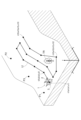
- the relative position control unit 32 can tilt the working device 3 to match the slope of the ground, as shown in FIG. 4.
- control unit 44 can control the flight of the flying object 2 using the flight control unit 31. Further, the control unit 44 can control the relative position of the flying object 2 and the working device 3 by the relative position control unit 32 .
- the control unit 44 controls the position of the working device 3 in the work space by integrally controlling the flight of the flying object 2 and controlling the relative position between the flying object 2 and the working device 3. .
- control unit 44 is configured to control the position of the work device 3 in the work space by controlling the flight of the flying object 2 by the flight control unit 31. More specifically, the control unit 44 controls the flight of the aircraft 2 using the flight control unit 31 and controls the relative position between the aircraft 2 and the work device 3 using the relative position control unit 32, thereby controlling the work. It is configured to control the position of the working device 3 in space.
- the main unit has a satellite positioning device 45.
- the satellite positioning device 45 receives GPS signals from artificial satellites used in GPS (Global Positioning System). Then, the satellite positioning device 45 calculates the position coordinates of the flight device 1 over time based on the received GPS signal.
- GPS Global Positioning System
- the satellite positioning device 45 does not need to use GPS.
- the satellite positioning device 45 may use GNSS (GLONASS, Galileo, Michibiki, BeiDou, etc.) other than GPS.
- GNSS GLONASS, Galileo, Michibiki, BeiDou, etc.
- the calculated positional coordinates of the flight device 1 over time are sent to the spatial position control unit 44.
- the main unit 42 also includes an acquisition section 47.
- the acquisition unit 47 acquires object information.
- the object information is information indicating the position and height of an object in the work space.
- the object is, for example, the ground, an obstacle, a crop, or the like. That is, the working flying object 1 (flying object 2 and working device 3) is controlled based on the three-dimensional shape of the work object.
- the work system includes the acquisition unit 47 that acquires object information that is information indicating the position and height of an object in the work space.
- the acquisition unit 47 may acquire object information from a management server (not shown) provided outside the work aircraft 1, for example, although it is not particularly limited. Further, for example, the acquisition unit 47 may acquire object information from a work vehicle such as a tractor or a combine harvester. Further, for example, the acquisition unit 47 includes an object sensor (not shown) that detects the position and height of an object around the work aircraft 1, and generates object information based on the detection result by this object sensor. By doing so, object information may be acquired. Further, the management server (not shown) may include a work plan storage unit that stores work plan information, and acquire object information based on work target position information included in the work plan storage unit.
- FIG. 5 shows an example of the content indicated by the object information acquired by the acquisition unit 47.
- the object information indicates the undulation of the ground in the three-dimensional work space and the position and height of the tree TR.
- FIG. 5 shows a first point P1, a second point P2, and a third point P3.
- the object information indicates, for example, the position and height of the ground at each of the first point P1, second point P2, and third point P3.
- the first point P1 and the second point P2 are both located on flat ground. Further, the second point P2 is located at a higher position than the first point P1. Further, the third point P3 is located on a slope. The third point P3 is located lower than the second point P2 and higher than the first point P1.
- the object information is sent from the acquisition unit 47 to the generation unit 46.
- the generation unit 46 generates time-series target position data based on the object information received from the acquisition unit 47.
- the time-series target position data is data indicating the target position of the flying object 2 or the work device 3 in the work space at each point in time within the scheduled work time.
- the work system includes the generation unit 46 that generates time-series target position data indicating the target position of the flying object 2 or the work device 3 in the work space at each point in time during the scheduled work time.
- the time-series target position data in this embodiment is data indicating the target position of the work device 3 in the work space at each point in time during the scheduled work time.
- FIG. 6 shows an example of time-series target position data.
- the target position of the work device 3 in the work space at each point in time from time t1 to time t15 is shown.
- time t1 is the work start time
- time t15 is the work end time.
- the period from time t1 to time t15 corresponds to the "scheduled work time" according to the present invention.
- the target position of the work device 3 in the work space is represented by a combination of the x-coordinate value, y-coordinate value, and z-coordinate value in the three-dimensional space.
- the target position at time t1 is a position where the x-coordinate value is a1, the y-coordinate value is b1, and the z-coordinate value is c1.
- the target position at time t2 is a position where the x-coordinate value is a2, the y-coordinate value is b2, and the z-coordinate value is c2.
- the target position at time t15 is a position where the x-coordinate value is a15, the y-coordinate value is b15, and the z-coordinate value is c15.
- each target position indicated by the time-series target position data shown in FIG. 6 is plotted. As shown in FIG. 5, a line connecting each target position in chronological order becomes the target movement route LI of the working device 3.
- the generation unit 46 may be configured to generate the target travel route LI.
- the generation unit 46 generates a target position at time t12 so that the flight device 1 detours around the tree TR based on information indicating the position and height of the tree TR included in the object information. Determine.
- the time-series target position data generated by the generation unit 46 is sent to the control unit 44, as shown in FIG.
- the control unit 44 controls the position of the work device 3 in the work space based on the position coordinates of the flight device 1 received from the satellite positioning device 45 and the time-series target position data received from the generation unit 46.
- control unit 44 controls the position of the working device 3 so that the working device 3 moves according to the time-series target position data.
- the flight control unit 31 controls the flight motor 22 so that the work device 3 is located at the target position corresponding to the time indicated by the time-series target position data.
- the flight control unit 31 controls the flight motor 22 at time t1 so that the work device 3 is located at the target position corresponding to time t1. Further, the flight control unit 31 controls the flight motor 22 at time t2 so that the work device 3 is located at the target position corresponding to time t2.
- control unit 32 controls the winch 51 so as to compensate for errors in the position control of the work device 3 by the flight control unit 31.
- the work device 3 moves along the target movement route LI shown in FIG. 5 while performing a predetermined work.
- the flight control unit 31 controls the flight of the aircraft 2 based on the time-series target position data.
- the time-series target position data is generated based on the object information acquired by the acquisition unit 47. That is, the flight control unit 31 controls the flight of the flying object 2 based on the object information acquired by the acquisition unit 47.
- the generation unit 46 generates the target movement route LI
- the target movement route LI is sent to the spatial position control unit 44. Then, the spatial position control unit 44 controls the work aircraft 1 so that the work device 3 moves along the target movement path LI.
- the working device 3 can change its state between a driving state and a stopped state.
- the driving state is a state in which driving is possible.
- the stopped state is a state in which the motor is not driven.
- the working device 3 can change its state between a power-on state and a power-off state.
- the power-on state corresponds to the driving state.
- the power off state corresponds to a stopped state.
- the working device 3 is configured to be driven by receiving power from a drive source such as an engine, and a clutch in the power transmission path to the working device 3 can be switched between an on state and a disengaged state. It may be configured.
- the state in which the clutch is in the engaged state corresponds to the driving state.
- a state in which the clutch is in a disengaged state corresponds to a stopped state.
- the working device 3 can change its state between the drive state, which is a state in which it can be driven, and the stopped state, which is a state in which it is not driven.
- the working device 3 continues to be driven while the power is on. That is, the chemical sprayer A1 continues to spray the chemical while the power is on.
- the present invention is not limited thereto, and the working device 3 may be configured to be driven only when a predetermined instruction signal is received while the power is on.
- the control section 44 includes a switching section 48.
- the switching unit 48 can switch the state of the working device 3 between a driving state and a stopped state. More specifically, the switching section 48 outputs a switching signal to the working device control section 52 to switch the state of the working device 3 between a power-on state and a power-off state.
- the switching section 48 transmits a command signal to turn on the power to the work device control section 52 provided in the work device 3 to switch the work device 3 to the power on state, and performs the work provided in the work device 3.
- a command signal to turn off the power is sent to the device control unit 52 to switch the working device 3 to the power off state.
- the control unit 44 uses information regarding the position coordinates of the work aircraft acquired over time from the satellite positioning device 45 (in this embodiment, three-dimensional position information including the height position in addition to the plane position), and the time-series information. If the difference exceeds a predetermined threshold based on the target position data, the switching section 48 sends a command signal to the working device control section 52 included in the working device 3 to stop driving the working device 3. , transmits a command signal to turn off the power to the work device 3. As a result, the driving of the working device 3 is stopped.
- the switching section 48 and the work device control section correspond to the "work control section" of the present invention.
- the work control section switching section 48 and work device control section 52 stops driving the work device 3 by turning off the power of the work device 3 has been described as an example. It is not limited to. If the clutch in the power transmission path to the working device 3 is configured to be switchable between an on state and a disengaged state, driving of the working device 3 may be stopped by setting the clutch in the disengaged state.
- the aircraft 2 is equipped with a notification device 70.
- the notification device 70 includes, for example, a buzzer, a notification lamp, a speaker capable of generating audio information, and the like.
- the notification device 70 notifies to that effect.
- the notification device 70 may notify that the driving of the working device 3 will be stopped. In this case, for example, if the condition for stopping the driving of the working device 3 is resolved within a predetermined period of time after the notification is given by the notification device 70, the driving of the working device 3 may not be stopped. May be controlled.
- the notification device 70 is not limited to the one provided in the aircraft 2, but may be provided in the work device 30, for example, or may be provided in a mobile terminal, remote control, etc. owned by a worker, a supervisor, a manager, etc. .
- the notification device 70 may be provided as hardware, may be provided as software, or may be provided as a combination of these.
- suppressing the driving of the working device 3 include, in addition to stopping the driving of the working device 3 described above, reducing the degree of driving such as the driving speed and driving force of the working device 3, and Examples include notifications to urge the driver to stop driving or reduce the degree of driving. Furthermore, in a state where the work device 3 is not driven, maintaining the state in which the work device 3 is not driven is also included in the above-mentioned suppression. Note that these notifications may be made via the notification device 70 described above.
- control may be performed in consideration of the relationship between the actual time, the time-series target position, and the target time in the data. That is, in addition to the above control, for example, even if the target time in the time-series target position data and the actual time exceed a predetermined threshold, the control to suppress the drive of the work device 3 described above may be performed. good.
- a field, a forest, a construction site, a construction site, etc. to be worked on is set as the work target area, and the set Control may be performed to suppress the driving of the work device 3 when the work device 3 deviates from the work target area or exceeds a predetermined threshold value from the work target area.
- control may be performed to suppress the driving of the work device 3 when the current time is outside the scheduled work time or when the current time exceeds a predetermined threshold and is outside the scheduled work time.
- the work plan information stored in the work information storage unit described above can include scheduled work time information regarding the scheduled work time for performing work on the work object, and the current time can be determined based on the scheduled work time information. Control may be performed to suppress the driving of the work device 3 when the work is outside the scheduled work time or when the current time exceeds a predetermined threshold and the work is outside the scheduled work time.
- the flight device 1 includes a distance detection device 34 (corresponding to the "distance measurement section” and “approach detection section” according to the present invention).
- the distance detection device 34 can measure the distance between the working device 3 and the ground by detecting the distance between the working device 3 and the ground.
- the work system SY includes a distance detection device 34 that measures the distance between the work device 3 and the ground.
- the distance detection device 34 can detect the approach state between the work device 3 and the work target. For example, when the work device 3 is a chemical sprayer A1, the work target is a crop.
- the work system SY includes a distance detection device 34 that detects the approach state between the work device 3 and the work target.
- the distance detection device 34 uses, for example, a camera, radar, LiDAR (laser radar), etc. to measure the distance between the work device 3 and the ground, and also determines the proximity state between the work device 3 and the work target. It may be configured to detect.
- a camera for example, a camera, radar, LiDAR (laser radar), etc.
- LiDAR laser radar
- the relative position control unit 32 controls each winch 51 based on this information. At this time, for example, the relative position control unit 32 controls each winch 51 so that the distance between the working device 3 and the ground is maintained at a constant distance.
- the relative position control unit 32 controls the winch 51 based on the measurement result by the distance detection device 34.
- the work aircraft 1 includes a transmission section 35.
- the transmission section 35 may be, for example, a known cable.
- the transmission unit 35 connects the flying object 2 and the working device 3. That is, the transmission section 35 is provided across the flying object 2 and the working device 3.
- connection section 35 is a member different from the connection mechanism 5. Moreover, each connection mechanism 5 and the transmission part 35 are spaced apart. That is, the connection mechanism 5 and the transmission section 35 are provided separately.
- the transmission section 35 is configured to be able to transmit electric power and electrical signals. However, the present invention is not limited to this, and the transmission section 35 may be configured to be able to transmit only one of the electric power and the electric signal.
- the work system SY includes a transmission section 35 capable of transmitting at least one of energy and electrical signals.
- the first battery 26 may be able to supply power to the second battery 30 via the transmission section 35.
- the second battery 30 may be able to supply power to the first battery 26 via the transmission section 35.
- the switching unit 48 switches the state of the working device 3 between the power-on state and the power-off state by sending an electric signal to the working device control unit 52 of the working device 3 via the transmission unit 35. It may be configured as follows.
- the work aircraft 1 includes a wireless transmission section 36.
- the wireless transmission section 36 includes a first member 36a and a second member 36b.
- the first member 36a is attached to the main body portion 20 of the flying object 2.
- the second member 36b is attached to the working device 3.
- the first member 36a and the second member 36b are configured to be able to transmit electric power and electric signals between each other by wireless connection.
- the wireless transmission unit 36 can transmit electric power and electric signals between the flying object 2 and the working device 3 by wireless connection.
- the present invention is not limited to this, and the wireless transmission section 36 may be configured to be able to transmit only one of electric power and electric signals.
- the work system SY includes a wireless transmission unit 36 that can transmit at least one of energy and electrical signals between the flying object 2 and the work device 3 via a wireless connection.
- the wireless transmission unit 36 may be configured to be able to transmit power using, for example, known wireless power transmission technology. Moreover, the wireless transmission unit 36 may be configured to be able to transmit electrical signals using a known short-range wireless communication technology.
- the first battery 26 may be able to supply power to the second battery 30 via the wireless transmission section 36.
- the second battery 30 may be able to supply power to the first battery 26 via the wireless transmission section 36.
- the switching unit 48 changes the state of the working equipment 3 between the power-on state and the power-off state by sending an electric signal to the working equipment control unit 52 of the working equipment 3 via the wireless transmission unit 36. It may be configured to switch.
- the wireless transmission section 36 is not provided. You don't have to.
- the transmission section 35 is provided. It doesn't have to be.
- the work system SY includes a sensing aircraft 37.
- the sensing flying object 37 is configured to be able to fly using the same mechanism as the flying object 2.
- the work system SY is equipped with a sensing flying object 37 that can fly.
- the sensing aircraft 37 has an event detection unit 38 (corresponding to the environmental situation detection device of the present invention).
- the event detection unit 38 is configured to detect events related to the work environment.
- the working environment is more specifically the weather. That is, the event detection unit 38 is configured to detect weather-related events.
- the sensing aircraft 37 has the event detection unit 38 that detects events related to the work environment.
- the work environment is the weather.
- the event detection unit 38 detects rain and wind. Note that rain and wind are specific examples of weather-related events.
- the event detection unit 38 may be configured to be able to detect not only the presence or absence of rain or wind, but also the strength of rain or wind.
- the main unit 42 has an environment prediction section 49.
- the detection results by the event detection section 38 are sent to the environment prediction section 49 via, for example, a management computer (not shown) or an Internet line.
- the environment prediction unit 49 predicts the future work environment (environmental situation) in the work space where the flight device 1 performs work based on the detection result (environmental situation) by the event detection unit 38.
- the future work environment predicted by the environment prediction unit 49 may be, for example, the work environment one hour from now, or may be the change in the work environment from now until sunset.
- the work system SY includes the environment prediction unit 49 that predicts the work environment in the work space. Further, the environment prediction unit 49 predicts the work environment based on the detection result by the event detection unit 38.
- the detection flying object 37 is flying in the first field F1.
- the flying device 1 is flying in the second field F2. It is assumed that the first field F1 and the second field F2 are separated from each other. Further, it is assumed that the first field F1 is located on the west side of the second field F2.
- the environment prediction unit 49 predicts that it will start raining and a relatively strong wind will blow in the second field F2 in one hour, for example.
- the prediction result by the environment prediction section 49 is sent to the flight control section 31.
- the flight control unit 31 controls the flight of the flying object 2 based on the prediction result by the environment prediction unit 49. For example, when the environment prediction unit 49 predicts that the working environment will deteriorate, the flight control unit 31 is configured to control the flight of the flying object 2 so as to evacuate the flight device 1 to a predetermined evacuation location. It's okay.
- the flight control unit 31 may change the preset work route based on the prediction result (prediction of the environmental situation) by the environment prediction unit 49. For example, based on the wind direction and wind speed determined by the environment prediction unit 49, the flight control unit 31 may change the preset target movement route LI (work route) so as to offset it to the windward side. At this time, based on the wind speed, the offset value may be set such that the offset amount increases as the wind speed increases, taking into consideration the degree to which the sprayed medicine is swept downwind by the wind.
- an event detection unit 38 may be provided in the work aircraft 1 to detect environmental conditions such as rain and wind, and the above-mentioned target movement route LI may be offset based on this environmental condition.
- the work device 3 includes the chemical spraying device A1
- the work device 3 is not limited to this.
- the working device 3 may include a snow removal device A2.
- the snow removal device A2 may include a spraying device that sprays a snow melting agent.
- this flying object 2 has two main wings 21a and one tail 21b. These two main wings 21a are tiltable, and by tilting the main wings 21a and changing the attitude of the main wings 21a, flights such as vertical landing flight, hovering flight, and high-speed flight are possible.
- the working device 3 may include a tilling device, a chemical application device, a fertilization device, a seeding device, a seedling transplanting device, a crop harvesting device, etc. Further, a plurality of working devices 3 may be provided.
- a tillage device for example, a general plow or rotary can be used.
- cultivation may be carried out by digging up the field with a drill.
- spray materials with a tillage effect such as gunpowder, earthworms, insects, moles, etc.
- a conventional seedling planting device can be used, or a device that throws seedlings may be used.
- the above working device may be supported by fixing a buoyancy ensuring body such as a balloon with an anchor or the like so that the buoyancy ensuring body can be moved relative to the buoyancy ensuring body.
- a buoyancy ensuring body such as a balloon with an anchor or the like
- the above-mentioned work aircraft 1 can also be suitably utilized for rooftop wall greening. Further, the above-mentioned work aircraft can be suitably used on water, on soft ground, in a narrow space inside a house, on a mountainside, on a cliff, etc. It can also be used at construction sites, construction sites, etc.
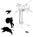
- the working aircraft 1 includes a monitoring device A3 as the working device 3 for performing monitoring work.
- the monitoring device A3 include, but are not limited to, a monitoring camera, an infrared sensor, a thermograph, a laser sensor, an ultrasonic sensor, and the like.
- the flying object 2 also includes a repelling device A4 as a working device 3 for repelling suspicious persons and birds and beasts.
- the repelling device A4 is not particularly limited as long as it can repel suspicious persons and birds and beasts, but examples include ultrasonic generators, sonic generators, light generators, stun guns, bitter, sour, pungent, and salty devices. Examples include devices that impart flavor.
- the work flying vehicle 1 itself may be used as the repelling device repelling device A4, such as by ramming the working flying vehicle 1.
- These monitoring work and repulsion work may be performed by a plurality of work aircraft 1 flying in a group, or may be performed cooperatively by a plurality of work aircraft 1 flying in their respective areas. It's okay.
- group monitoring or repelling work it is conceivable that, for example, the work aircraft 1 belonging to the area where the suspicious person or bird or beast has appeared, or the work aircraft 1 belonging to the neighboring area, perform the work in a group.
- the monitoring device A3 may perform individual recognition and, for example, intensively repel the boss of the group, or grasp behavioral trends of birds, beasts, and suspicious persons, and take appropriate repelling actions.
- the work aircraft may be equipped with a reporting device that provides notification based on the monitoring results of the monitoring device A3.
- the reporting device can send a report to, for example, a mobile terminal of a worker, a manager, a supervisor, or the like.
- the notification device may be used to notify a police station, fire department, hunter, or the like.
- the work aircraft may be equipped with a marking device that marks the monitoring target based on the monitoring results of the monitoring device A3.
- a marking device that marks the monitoring target based on the monitoring results of the monitoring device A3.
- a paint gun can be used as the marking device.
- the scarecrow may be configured with a working flying vehicle 1, and may be a multi-functional scarecrow that assists in monitoring, repelling, assisting the position accuracy of the satellite positioning device, and assisting the work of the main working machine.
- monitoring and repulsion history information can be shared, for example, on a regional management server, or communication between work flying vehicles 1 can be used to identify individuals, identify the status of bird and beast damage, predict crime, and improve effective results. You may also share strategies for repelling them.
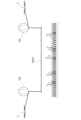
- the work aircraft 1 can be equipped with a work environment improvement device A5 as the work device 3 that improves the work environment in at least one of the work object and the surrounding area of the work object.
- the work environment improvement device A5 is a roof device that performs light shielding, heat shielding, rainproofing, etc. in the work area.
- This roof device includes a balloon 100 and a roof section formed of, for example, a canopy.
- Four balloons 100 are provided, for example, corresponding to each of the four corners of the roof, and are connected to the roof through wires.
- four flying objects 2 are connected to the wires of each balloon. This keeps the roof arrangement above the working area.
- This roof device improves the working environment by blocking light, heat shielding, rainproofing, etc.
- This roof device may be kept stationary in the sky, or may be moved to form a movable (following) roof device.
- a blower device that blows air for air conditioning such as cooling or air for an air curtain can be applied.
- the blower device may be stopped in the sky, or may be moved and used as a follow-up spot cooler.
- the work environment improvement device A5 may be a water or fragrance source spraying device or a relaxing sound or noise canceling sound generating device.
- work environment improvement device A5 is applicable not only to agricultural work in fields and forests, construction sites, and construction sites, but also to amusement parks, theme parks, sports facilities, and the like.
- the work aircraft 1 includes, as the work device 3, at least one of a material transport device that transports materials to another work device 3, and a harvest transport device that transports harvested products from the other work device 3. But that's fine.
- the material transport device that transports materials to other working devices 3 include a material transport device that transports seedlings, fertilizers, medicines, etc. to a rice transplanter.
- a harvest conveyance device which conveys a harvest from another working device 3 for example, a material conveyance device which conveys grain, which is a harvest from a combine harvester, to a rice cart.
- These working flying vehicles 1 for transporting materials and working flying vehicles 1 for transporting crops may be provided with dedicated flying vehicles, or the above-mentioned working flying vehicles 1 may also be used.
- the winch 51 may be attached to the flying object 2.
- the transmission section 35 may be configured to be able to send fuel to the engine.
- the transmission section 35 may be configured to be able to transmit heat or power. In this case, both heat and power correspond to "energy” according to the present invention.
- the work system SY may include a position prediction unit that predicts the position of the work device 3 when the flying object 2 is accelerating, decelerating, or turning.
- the flight control unit 31 may be configured to control the flight of the flying object 2 based on the prediction result by the position prediction unit.
- the position prediction unit calculates the positional deviation of the working device 3 with respect to the flying object 2. By doing so, the position of the working device 3 is predicted. Then, based on this prediction result, the flight control unit 31 controls the flight of the flying object 2 when turning so that the flying object 2 is located on the inside of the turning than the target trajectory of the working device 3 when turning.
- the main unit 42 may be configured to control the flight motor 22, winch 51, and work device 3 based on various information.
- the information may be, for example, information obtained by a mobile sensor or a fixed sensor located at the work site or around the work site.
- the mobile sensor may be, for example, a sensor provided in a self-propelled work machine.
- the fixed sensor may be, for example, a multi-functional scarecrow, a GPS base station, a surveillance camera, a sensor provided in a wildlife damage prevention fence, or the like.
- the information may be, for example, information obtained from smart machines linked to the supply chain.
- the main unit 42 acquires operating information of a grain dryer that is equipped with a harvesting device as the working device 3 and is configured as a smart machine linked to the supply chain, and based on the operating information, The main unit 42 may control the flight motor 22, the winch 51, and the work device 3 so that the harvest timing is optimal.
- a tilling rotor is provided as the working device 3, and the flight control unit 31 drives the flight motor 22 in the direction in which the flying object 2 descends, so that the working flying object 1 pushes the tilling rotor downward. It may also be configured to fly while As a result, it is possible to realize a work aircraft 1 that can perform plowing work equivalent to plowing work using a conventional work vehicle.
- flight control unit 31, relative position control unit 32, spatial position control unit 44, generation unit 46, acquisition unit 47, switching unit 48, and environment prediction unit 49 are external to the work aircraft 1.
- it may be provided in a management computer provided outside the work aircraft 1.
- the connection mechanism 5 may have the function of the transmission section 35.
- the transmission section 35 may or may not be provided.
- the connection mechanism 5 may transmit at least one of the energy and the electric signal instead of the transmission section 35 when a malfunction occurs in the transmission section 35 .
- the work aircraft 1 may be configured to cancel the operating sound of the propeller 21.
- the operations of the plurality of propellers 21 may be controlled so that their operating sounds cancel each other out.
- the work aircraft 1 may be provided with a muffling device that generates a sound (noise canceling sound) that cancels the operating sound of the propeller 21.
- the silencer may be configured to generate a noise canceling sound based on the control amount sent to the flight motor 22.
- connection structure between the winch 51 and the work device 3 is designed as a common standard for various types of work devices 3, and is configured so that various types of work devices 3 can be connected to the winch 51. You can leave it there.
- connection structure between the flying object 2 and the connecting mechanism 5 is designed as a common standard for various types of flying objects 2, and various types of flying objects 2 can be connected to the connecting mechanism 5. It may be configured as follows.
- the propeller 21 may be configured to be rotatable about a rotation axis of the propeller 21 that extends in the left-right direction of the aircraft. That is, the propeller 21 may be of a so-called tilt type. With this configuration, the work aircraft 1 is capable of vertical takeoff and landing, hovering flight, and high-speed horizontal flight.
- the work aircraft 1 or another aircraft may be provided with a work result acquisition unit that acquires the results of work performed by the work device 3. Based on the work results acquired by the work result acquisition unit, the work plan creation unit can create, for example, a work plan for subsequent processes or a work plan for the next year and thereafter. If this work plan is saved in the work plan storage section of the management server, it can be utilized for subsequent processes and work from the next year onward.
- the data generated by the generation unit 46 does not need to include information indicating time.
- the generation unit 46 generates target position data that is data indicating the target position of the flying object 2 or the work device 3 in the work space, and in this target position data, time is associated with the target position. You don't have to.
- this target position data may be the time-series target position data shown in FIG. 6 from which information indicating time has been deleted.
- the target position may be expressed, for example, as a combination of x-coordinate values, y-coordinate values, and z-coordinate values in a three-dimensional space, similarly to the above embodiment.
- the flight control unit 31 may be configured to control the flight of the flying object 2 based on this target position data.
- the environment prediction unit 49 may predict the work environment based on any information other than the information acquired from the sensing aircraft 37 or the event detection unit 38.
- the environment prediction unit 49 uses information obtained from some or all of fixed sensors, the Internet, sensors of work equipment 3, etc. in other work aircraft 1, and sensors of work machines such as tractors.
- the work environment may be predicted based on the information.
- the present invention can be used in a work system that includes a work device that can perform predetermined work.
Landscapes
- Engineering & Computer Science (AREA)
- Aviation & Aerospace Engineering (AREA)
- Automation & Control Theory (AREA)
- Control Of Position, Course, Altitude, Or Attitude Of Moving Bodies (AREA)
Abstract
Le problème décrit par la présente invention est de fournir un véhicule aérien pouvant réaliser de manière appropriée un travail lorsque le véhicule aérien doit être utilisé dans divers travaux. La solution selon l'invention porte sur un véhicule aérien 2, un dispositif de travail 3 pouvant réaliser un travail désigné, et une unité de commande de travail qui commande le dispositif de travail 3, l'unité de commande de travail permettant au dispositif de travail 3 d'être actionné lorsque le dispositif de travail est positionné au niveau d'une position cible de travail et empêchant le dispositif de travail 3 d'être actionné lorsque le dispositif de travail n'est pas positionné au niveau de la position cible de travail.
Priority Applications (1)
| Application Number | Priority Date | Filing Date | Title |
|---|---|---|---|
| PCT/JP2022/018265 WO2023203668A1 (fr) | 2022-04-20 | 2022-04-20 | Véhicule aérien d'exécution de travail |
Applications Claiming Priority (1)
| Application Number | Priority Date | Filing Date | Title |
|---|---|---|---|
| PCT/JP2022/018265 WO2023203668A1 (fr) | 2022-04-20 | 2022-04-20 | Véhicule aérien d'exécution de travail |
Publications (1)
| Publication Number | Publication Date |
|---|---|
| WO2023203668A1 true WO2023203668A1 (fr) | 2023-10-26 |
Family
ID=88419587
Family Applications (1)
| Application Number | Title | Priority Date | Filing Date |
|---|---|---|---|
| PCT/JP2022/018265 WO2023203668A1 (fr) | 2022-04-20 | 2022-04-20 | Véhicule aérien d'exécution de travail |
Country Status (1)
| Country | Link |
|---|---|
| WO (1) | WO2023203668A1 (fr) |
Citations (8)
| Publication number | Priority date | Publication date | Assignee | Title |
|---|---|---|---|---|
| JP2014177162A (ja) * | 2013-03-14 | 2014-09-25 | Secom Co Ltd | 撮影システム |
| JP2016173738A (ja) * | 2015-03-17 | 2016-09-29 | セコム株式会社 | 飛行ロボット制御システム及び飛行ロボット |
| JP2018511245A (ja) * | 2015-03-31 | 2018-04-19 | エスゼット ディージェイアイ テクノロジー カンパニー リミテッドSz Dji Technology Co.,Ltd | Uav搭載物制御システム |
| US20180357909A1 (en) * | 2015-12-09 | 2018-12-13 | Dronesense Llc | Drone Flight Operations |
| WO2020111096A1 (fr) * | 2018-11-27 | 2020-06-04 | 株式会社ナイルワークス | Dispositif de planification de travail, procédé de commande de dispositif de planification de travail ainsi que programme de commande associé et drone |
| JP6747618B1 (ja) * | 2020-06-09 | 2020-08-26 | 東洋製罐株式会社 | 情報管理方法および情報管理システム |
| WO2021015277A1 (fr) * | 2019-07-23 | 2021-01-28 | 東洋製罐株式会社 | Système de décharge, dispositif de décharge, aéronef sans pilote, système de pilotage et contenant d'aérosol |
| WO2021074968A1 (fr) * | 2019-10-15 | 2021-04-22 | 楽天株式会社 | Aéronef |
-
2022
- 2022-04-20 WO PCT/JP2022/018265 patent/WO2023203668A1/fr unknown
Patent Citations (8)
| Publication number | Priority date | Publication date | Assignee | Title |
|---|---|---|---|---|
| JP2014177162A (ja) * | 2013-03-14 | 2014-09-25 | Secom Co Ltd | 撮影システム |
| JP2016173738A (ja) * | 2015-03-17 | 2016-09-29 | セコム株式会社 | 飛行ロボット制御システム及び飛行ロボット |
| JP2018511245A (ja) * | 2015-03-31 | 2018-04-19 | エスゼット ディージェイアイ テクノロジー カンパニー リミテッドSz Dji Technology Co.,Ltd | Uav搭載物制御システム |
| US20180357909A1 (en) * | 2015-12-09 | 2018-12-13 | Dronesense Llc | Drone Flight Operations |
| WO2020111096A1 (fr) * | 2018-11-27 | 2020-06-04 | 株式会社ナイルワークス | Dispositif de planification de travail, procédé de commande de dispositif de planification de travail ainsi que programme de commande associé et drone |
| WO2021015277A1 (fr) * | 2019-07-23 | 2021-01-28 | 東洋製罐株式会社 | Système de décharge, dispositif de décharge, aéronef sans pilote, système de pilotage et contenant d'aérosol |
| WO2021074968A1 (fr) * | 2019-10-15 | 2021-04-22 | 楽天株式会社 | Aéronef |
| JP6747618B1 (ja) * | 2020-06-09 | 2020-08-26 | 東洋製罐株式会社 | 情報管理方法および情報管理システム |
Similar Documents
| Publication | Publication Date | Title |
|---|---|---|
| US11117663B2 (en) | Apparatus and method for unmanned flight | |
| US20180074518A1 (en) | Apparatus and method for unmanned flight task optimization | |
| US20180065747A1 (en) | Systems and methods for dispensing an insecticide via unmanned vehicles to defend a crop-containing area against pests | |
| US20150127209A1 (en) | Bird repellent system | |
| US20180074499A1 (en) | Apparatus and method for monitoring a field | |
| US20180064094A1 (en) | Systems and methods for defending crops from crop-damaging pests via unmanned vehicles | |
| US11147257B2 (en) | Software process for tending crops using a UAV | |
| KR101142737B1 (ko) | 조류 대응 시스템 | |
| US20190110461A1 (en) | Method and apparatus for identifying, locating and scaring away birds | |
| US20180068165A1 (en) | Systems and methods for identifying pests in crop-containing areas via unmanned vehicles based on crop damage detection | |
| AU2021270468A1 (en) | Obstacle monitoring systems and methods for same | |
| US20180068164A1 (en) | Systems and methods for identifying pests in crop-containing areas via unmanned vehicles | |
| US20190152595A1 (en) | Apparatus for Sustained Surveillance and Deterrence with Unmanned Aerial Vehicles (UAV) | |
| US20200201332A1 (en) | Surveillance system for a wind park, and associated method | |
| KR102200384B1 (ko) | 유해 조류 퇴치 시스템 | |
| WO2023203668A1 (fr) | Véhicule aérien d'exécution de travail | |
| CN116569910A (zh) | 一种飞行驱鸟系统及驱鸟方法 | |
| US20210243565A1 (en) | Object tracking systems and methods | |
| AU2020202481B2 (en) | Pest control assembly, system and method | |
| WO2023203670A1 (fr) | Système de travail | |
| WO2023203667A1 (fr) | Aéronef et système d'assistance au travail utilisant un aéronef | |
| WO2023203673A1 (fr) | Système de commande d'objet volant et système d'objet volant | |
| JP2019158540A (ja) | 情報提供システム、位置送信装置、情報収集装置及び情報提供装置 | |
| CA2985600A1 (fr) | Appareil de surveillance et dissuasion continues comportant des vehicules aeriens teleguides |
Legal Events
| Date | Code | Title | Description |
|---|---|---|---|
| 121 | Ep: the epo has been informed by wipo that ep was designated in this application |
Ref document number: 22938471 Country of ref document: EP Kind code of ref document: A1 |