WO2023199733A1 - ノイズ低減具及びワイヤハーネス - Google Patents
ノイズ低減具及びワイヤハーネス Download PDFInfo
- Publication number
- WO2023199733A1 WO2023199733A1 PCT/JP2023/012058 JP2023012058W WO2023199733A1 WO 2023199733 A1 WO2023199733 A1 WO 2023199733A1 JP 2023012058 W JP2023012058 W JP 2023012058W WO 2023199733 A1 WO2023199733 A1 WO 2023199733A1
- Authority
- WO
- WIPO (PCT)
- Prior art keywords
- electric wire
- magnetic body
- noise reduction
- bundle
- wire bundle
- Prior art date
- Legal status (The legal status is an assumption and is not a legal conclusion. Google has not performed a legal analysis and makes no representation as to the accuracy of the status listed.)
- Ceased
Links
Images




Classifications
-
- H—ELECTRICITY
- H05—ELECTRIC TECHNIQUES NOT OTHERWISE PROVIDED FOR
- H05K—PRINTED CIRCUITS; CASINGS OR CONSTRUCTIONAL DETAILS OF ELECTRIC APPARATUS; MANUFACTURE OF ASSEMBLAGES OF ELECTRICAL COMPONENTS
- H05K9/00—Screening of apparatus or components against electric or magnetic fields
-
- H—ELECTRICITY
- H02—GENERATION; CONVERSION OR DISTRIBUTION OF ELECTRIC POWER
- H02G—INSTALLATION OF ELECTRIC CABLES OR LINES, OR OF COMBINED OPTICAL AND ELECTRIC CABLES OR LINES
- H02G3/00—Installations of electric cables or lines or protective tubing therefor in or on buildings, equivalent structures or vehicles
- H02G3/02—Details
- H02G3/04—Protective tubing or conduits, e.g. cable ladders or cable troughs
-
- B—PERFORMING OPERATIONS; TRANSPORTING
- B60—VEHICLES IN GENERAL
- B60R—VEHICLES, VEHICLE FITTINGS, OR VEHICLE PARTS, NOT OTHERWISE PROVIDED FOR
- B60R16/00—Electric or fluid circuits specially adapted for vehicles and not otherwise provided for; Arrangement of elements of electric or fluid circuits specially adapted for vehicles and not otherwise provided for
- B60R16/02—Electric or fluid circuits specially adapted for vehicles and not otherwise provided for; Arrangement of elements of electric or fluid circuits specially adapted for vehicles and not otherwise provided for electric constitutive elements
-
- H—ELECTRICITY
- H01—ELECTRIC ELEMENTS
- H01F—MAGNETS; INDUCTANCES; TRANSFORMERS; SELECTION OF MATERIALS FOR THEIR MAGNETIC PROPERTIES
- H01F1/00—Magnets or magnetic bodies characterised by the magnetic materials therefor; Selection of materials for their magnetic properties
- H01F1/01—Magnets or magnetic bodies characterised by the magnetic materials therefor; Selection of materials for their magnetic properties of inorganic materials
- H01F1/03—Magnets or magnetic bodies characterised by the magnetic materials therefor; Selection of materials for their magnetic properties of inorganic materials characterised by their coercivity
- H01F1/032—Magnets or magnetic bodies characterised by the magnetic materials therefor; Selection of materials for their magnetic properties of inorganic materials characterised by their coercivity of hard-magnetic materials
- H01F1/10—Magnets or magnetic bodies characterised by the magnetic materials therefor; Selection of materials for their magnetic properties of inorganic materials characterised by their coercivity of hard-magnetic materials non-metallic substances, e.g. ferrites, e.g. [(Ba,Sr)O(Fe2O3)6] ferrites with hexagonal structure
- H01F1/11—Magnets or magnetic bodies characterised by the magnetic materials therefor; Selection of materials for their magnetic properties of inorganic materials characterised by their coercivity of hard-magnetic materials non-metallic substances, e.g. ferrites, e.g. [(Ba,Sr)O(Fe2O3)6] ferrites with hexagonal structure in the form of particles
- H01F1/113—Magnets or magnetic bodies characterised by the magnetic materials therefor; Selection of materials for their magnetic properties of inorganic materials characterised by their coercivity of hard-magnetic materials non-metallic substances, e.g. ferrites, e.g. [(Ba,Sr)O(Fe2O3)6] ferrites with hexagonal structure in the form of particles in a bonding agent
- H01F1/117—Flexible bodies
-
- H—ELECTRICITY
- H01—ELECTRIC ELEMENTS
- H01F—MAGNETS; INDUCTANCES; TRANSFORMERS; SELECTION OF MATERIALS FOR THEIR MAGNETIC PROPERTIES
- H01F1/00—Magnets or magnetic bodies characterised by the magnetic materials therefor; Selection of materials for their magnetic properties
- H01F1/01—Magnets or magnetic bodies characterised by the magnetic materials therefor; Selection of materials for their magnetic properties of inorganic materials
- H01F1/03—Magnets or magnetic bodies characterised by the magnetic materials therefor; Selection of materials for their magnetic properties of inorganic materials characterised by their coercivity
- H01F1/12—Magnets or magnetic bodies characterised by the magnetic materials therefor; Selection of materials for their magnetic properties of inorganic materials characterised by their coercivity of soft-magnetic materials
- H01F1/34—Magnets or magnetic bodies characterised by the magnetic materials therefor; Selection of materials for their magnetic properties of inorganic materials characterised by their coercivity of soft-magnetic materials non-metallic substances, e.g. ferrites
- H01F1/36—Magnets or magnetic bodies characterised by the magnetic materials therefor; Selection of materials for their magnetic properties of inorganic materials characterised by their coercivity of soft-magnetic materials non-metallic substances, e.g. ferrites in the form of particles
- H01F1/37—Magnets or magnetic bodies characterised by the magnetic materials therefor; Selection of materials for their magnetic properties of inorganic materials characterised by their coercivity of soft-magnetic materials non-metallic substances, e.g. ferrites in the form of particles in a bonding agent
- H01F1/375—Flexible bodies
-
- H—ELECTRICITY
- H05—ELECTRIC TECHNIQUES NOT OTHERWISE PROVIDED FOR
- H05K—PRINTED CIRCUITS; CASINGS OR CONSTRUCTIONAL DETAILS OF ELECTRIC APPARATUS; MANUFACTURE OF ASSEMBLAGES OF ELECTRICAL COMPONENTS
- H05K9/00—Screening of apparatus or components against electric or magnetic fields
- H05K9/0073—Shielding materials
- H05K9/0098—Shielding materials for shielding electrical cables
-
- B—PERFORMING OPERATIONS; TRANSPORTING
- B60—VEHICLES IN GENERAL
- B60R—VEHICLES, VEHICLE FITTINGS, OR VEHICLE PARTS, NOT OTHERWISE PROVIDED FOR
- B60R16/00—Electric or fluid circuits specially adapted for vehicles and not otherwise provided for; Arrangement of elements of electric or fluid circuits specially adapted for vehicles and not otherwise provided for
- B60R16/02—Electric or fluid circuits specially adapted for vehicles and not otherwise provided for; Arrangement of elements of electric or fluid circuits specially adapted for vehicles and not otherwise provided for electric constitutive elements
- B60R16/0207—Wire harnesses
-
- H—ELECTRICITY
- H01—ELECTRIC ELEMENTS
- H01F—MAGNETS; INDUCTANCES; TRANSFORMERS; SELECTION OF MATERIALS FOR THEIR MAGNETIC PROPERTIES
- H01F17/00—Fixed inductances of the signal type
- H01F17/04—Fixed inductances of the signal type with magnetic core
- H01F17/06—Fixed inductances of the signal type with magnetic core with core substantially closed in itself, e.g. toroid
- H01F2017/065—Core mounted around conductor to absorb noise, e.g. EMI filter
Definitions
- the present invention relates to a noise reduction device and a wire harness.
- the noise reduction device is a member made of a magnetic material, and includes a magnetic material as a component that is attached to an electric wire through which a noise current flows to reduce the emission of radiated noise from the electric wire to the outside.
- a noise reduction tool includes two magnetic bodies (so-called ferrite cores) formed into a semi-cylindrical shape, and these two magnetic bodies are combined to form a cylinder, and an electric wire is inserted into the space inside the cylinder. It is used in an inserted form.
- ferrite cores two magnetic bodies formed into a semi-cylindrical shape
- Patent Document 1 listed below discloses a noise reduction device with a chain structure in which two types of magnetic bodies are arranged alternately and one of the adjacent cylindrical magnetic bodies is connected with an elastic member and a pin.
- Patent Document 2 listed below discloses a noise reduction device in which a plurality of trapezoidal columnar magnetic bodies are adhered to a film and the film is wound around an electric wire.
- the noise reduction device of Patent Document 1 has a complicated structure due to its large number of component parts, and it is difficult to reduce the cost from the viewpoint of productivity and the like. Further, in the noise reduction device of Patent Document 2, since the magnetic material and the film are bonded together with an adhesive, it is difficult to ensure durability from the viewpoint of heat resistance, aging, etc.
- an object of the present invention is to provide a noise reduction device and a wire harness that can keep the cost low while ensuring durability.
- the noise reduction device includes a band-shaped magnetic material that can be wrapped around an axis of an electric wire or a bundle of electric wires more than once around the axis of the electric wire or the electric wire bundle made of a plurality of electric wires; fixing the overlapping portions of the laminated parts of the magnetic body in a wound shape wound around the electric wire or the electric wire bundle, and fixing the magnetic body to the electric wire or the electric wire bundle while maintaining the winding shape of the magnetic body; a fixing member, the magnetic body can change a winding diameter according to the wire diameter of the electric wire or the wire bundle diameter of the electric wire bundle, and the fixing member has a winding diameter of the magnetic body Regardless, it is characterized in that the overlapping portions are fixed to each other in accordance with the winding diameter.
- the wire harness according to the present invention includes an electric wire or an electric wire bundle in which a plurality of electric wires are bundled together, and a noise reduction device that reduces emission of radiated noise from the electric wire or the electric wire bundle to the outside.
- the noise reduction device includes a band-shaped magnetic material that can be wrapped around the axis of the electric wire or the electric wire bundle more than once around the electric wire or the electric wire bundle; a fixing member that fixes overlapping portions of laminated portions of the wound magnetic body to each other and fixes the magnetic body to the electric wire or the electric wire bundle while maintaining the winding shape of the magnetic body;
- the winding diameter of the magnetic body can be changed according to the wire diameter of the electric wire or the wire bundle diameter of the electric wire bundle, and the fixing member can change the winding diameter of the magnetic body regardless of the winding diameter of the magnetic body. It is characterized in that the corresponding overlapping parts are fixed to each other.
- the noise reduction device has a simple structure in which the main components are only a magnetic body and a fixing member, and the magnetic body is simply wound around an electric wire or a bundle of electric wires and fixed with a fixing member. Therefore, this noise reduction tool has excellent productivity and can reduce cost.
- this noise reduction device can be applied to wires with various wire diameters and lengths, and wire bundles with various wire bundle diameters and lengths, so that it can be used in common among various wires and wire bundles. Therefore, the cost of this noise reduction tool can be reduced in this respect as well.
- this noise reduction device also has the function of bundling multiple electric wires into a wire bundle, so for example, it is possible to eliminate the need for cable ties or adhesive tape for bundling multiple electric wires. It is possible to reduce the number of tapes and the amount used. Therefore, the cost of this noise reduction tool can be reduced in this respect as well. Furthermore, since this noise reduction tool does not use adhesive, it has high heat resistance and resistance to changes over time, and can ensure high durability. In this way, the noise reduction device according to the present invention can keep the cost low while ensuring high durability.
- the wire harness according to the present invention includes this noise reduction device, and can produce the same effects as those obtained by this noise reduction device.
- FIG. 1 is a perspective view schematically showing a wire harness in which a noise reduction device according to an embodiment is assembled.
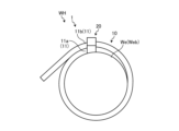
- FIG. 2 is a schematic diagram of the wire harness in which the noise reduction device of the embodiment is assembled, viewed in the axial direction.
- FIG. 3 is a plan view schematically showing the noise reduction tool before assembly.
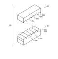
- FIG. 4 is a perspective view schematically showing an example of the fixing member.
- FIG. 5 is a plan view schematically showing an example of a state in which the overlapping portions are fixed to each other by a fixing member.
- FIG. 6 is a plan view schematically showing, together with another example, a state in which the overlapping portions are fixed to each other by a fixing member.
- FIGS. 1 to 6 One embodiment of a noise reduction device and a wire harness according to the present invention will be described based on FIGS. 1 to 6.
- the reference numeral 1 shown in FIGS. 1 and 2 indicates the noise reduction tool of this embodiment.
- This noise reduction tool 1 is attached to an electric wire We through which a noise current flows, and reduces emission of radiation noise from the electric wire We to the outside.
- the noise reduction tool 1 can be attached to an electric wire bundle Web (a wire bundle Web where a noise current flows among the plurality of electric wires) by attaching the electric wire This reduces the emission of radiated noise from the electric wire (We) to the outside.
- the symbol WH shown in FIGS. 1 and 2 indicates a wire harness in which the noise reduction tool 1 is assembled to the electric wire We or the electric wire bundle Web.
- One or more noise reduction tools 1 are provided depending on the length of the electric wire We or the electric wire bundle Web.
- This wire harness WH is mounted on an electric vehicle (not shown) such as a BEV (Battery Electric Vehicle) or a PHEV (Plug-in Hybrid Electric Vehicle), for example.
- this wire harness WH is installed between a secondary battery for driving an electric vehicle and a secondary battery for auxiliary equipment, and between a DC/DC converter and a secondary battery for auxiliary equipment interposed between the two. make a physical and electrical connection between the two.
- This wire harness WH is responsible for feeding power from the driving secondary battery to the auxiliary secondary battery when charging the auxiliary secondary battery.
- this wire harness WH is used, for example, in a charging system (not shown) for charging a secondary battery for driving and a secondary battery for auxiliary equipment of an electric vehicle.
- This charging system is configured for normal charging or quick charging, regardless of whether it is for business or home use.
- This charging system includes an external power source, a charger body supplied with power from the external power source, and a charging cable with a connector for feeding power from the charger body to the vehicle side.
- a charging cable with a connector is used by a worker when supplying power, and includes at least a charging cable provided with a power line (wire We) and a charging connector attached to one terminal of the charging cable. Be prepared.
- some charging systems perform charging control while communicating between the vehicle and the charger body during power supply.
- the charging cable in this case is also provided with a communication signal line responsible for the communication.
- a three-phase AC power source is used as the external power source, and an AC/DC converter that converts the AC voltage to DC voltage is housed in the casing of the charger body. ing.
- the charging cable with a connector supplies the converted power to the vehicle side.
- the charging cable with a connector is assembled in advance to the charger main body, and may constitute the charger together with the charger main body.
- This charging cable with a connector is routed from the charger main body side to the vehicle side when charging, and the charging connector is physically and electrically connected to the connector of the electric vehicle (vehicle side connector).
- the charging cable with a connector may be a separate component that is housed in the luggage compartment of a vehicle, and a power source side connector may be attached to the other end of the charging cable.
- the charger body constitutes a charger.
- the power supply side connector is physically and electrically connected to the connector on the charger body, and the charging connector is physically and electrically connected to the vehicle side connector. Connect.
- This charging system is provided with an internal charging cable that electrically connects the AC/DC converter side and the charging cable side within the casing of the charger main body.
- This internal charging cable includes at least an internal power line (electric wire We), and electrically connects the AC/DC converter side and the charging cable side by this internal power line. Therefore, in this charging system, the wire harness WH of this embodiment includes the internal charging cable to which the noise reduction tool 1 is attached. Note that when performing the above communication during charging, the internal charging cable is also provided with an internal communication signal line.
- the wire harness WH of this embodiment is a charging cable with a connector and the noise reduction device 1 attached thereto.
- the noise reduction device 1 includes a band-shaped magnetic material 10 that can be wrapped around the axis of the electric wire We or the electric wire bundle Web more than once, and a magnetic material 10 that can be wound around the electric wire We or the electric wire bundle Web.
- a fixing member that fixes the overlapping parts 11a and 11b of the laminated portion 11 of the magnetic body 10 in a wound shape, and fixes the magnetic body 10 to the electric wire We or the electric wire bundle Web while maintaining the winding shape of the magnetic body 10. 20 (FIGS. 1 to 6).
- the magnetic body 10 is made of a ferromagnetic material and is molded with flexibility. Ferrite or the like is used as the ferromagnetic material.
- This magnetic body 10 has a length that corresponds to the wire diameter of the wire We to be wound or the wire bundle diameter of the wire bundle Web, and is wound around the wire We or the wire bundle Web more than once.
- the overlapping portions 11a and 11b of the laminated portion 11 are formed into a belt shape having a length that allows the fixing member 20 to fix the overlapping portions 11a and 11b to each other.
- this magnetic body 10 can be wound more than once around the electric wire We of the maximum electric wire diameter or the electric wire bundle Web of the maximum electric wire bundle diameter, and the overlapping portion 11a of the laminated portion 11, 11b are formed into a belt shape with a length that allows them to be fixed together with the fixing member 20.
- the magnetic body 10 is an electric wire We having a wire diameter less than or equal to the maximum electric wire diameter or an electric wire bundle Web having an electric wire bundle diameter less than or equal to the maximum electric wire bundle diameter
- the magnetic body 10 can be The winding diameter can be changed depending on the bundle diameter.
- the fixing member 20 is formed to be capable of fixing the overlapping portions 11a and 11b to each other in accordance with the winding diameter, regardless of the winding diameter of the magnetic body 10.
- the fixing member 20 illustrated here has a protrusion that engages at least one of the overlapping parts 11a (11b) in the laminated portion 11 to fix the overlapping parts 11a and 11b to each other.
- the fixing member 20 has a first fixing part 21 and a second fixing part 22 (FIGS. 3 to 6).
- the first fixing part 21 and the second fixing part 22 may be separate from each other, or may be integrated via a living hinge or the like.
- a first fixing part 21 and a second fixing part 22 which are separate bodies are shown.
- a plurality of protrusions are provided on at least one of the first fixing part 21 and the second fixing part 22.
- a plurality of protrusions are provided on one of the first fixing part 21 and the second fixing part 22, and at least one overlapping part 11a (11b) is provided on the other of the protrusions.
- a clamping part is provided between the two.
- the holding portion may be a wall surface such as a smooth surface on the other of the first fixing portion 21 and the second fixing portion 22, or may be a groove for each protrusion that pairs with the protrusion.
- the first fixing part 21 shown here has a plurality of first protrusions 20a and first grooves 20b arranged alternately (FIG. 4).
- the second fixing part 22 shown here has a plurality of second protrusions 20c and second grooves 20d arranged alternately (FIG. 4).
- one first protrusion 20a and one second groove 20d form a pair
- one second protrusion 20c and one first groove 20b form a pair.
- the first protrusion 20a and the second groove 20d are formed in a shape that allows the first protrusion 20a to fit into the second groove 20d for each combination.
- the second protrusion 20c and the first groove 20b are formed in a shape that allows the second protrusion 20c to fit into the first groove 20b for each combination.
- the first fixing part 21 is integrated with one end of the magnetic body 10 in the longitudinal direction (FIG. 3).
- one end of the magnetic body 10 becomes one overlapping part 11a, and the other overlapping part 11b exists at the other end in the longitudinal direction of the magnetic body 10 after winding.
- the first fixing portion 21 may be formed integrally with the magnetic body 10 using the same ferromagnetic material as the magnetic body 10 if its shape can be shaped.
- the first fixing part 21 can be made of an insulating material such as synthetic resin using the integral molding technique. It can be made of any material.
- the magnetic body 10 is wound around the electric wire We or the electric wire bundle Web, and the other end side of the magnetic body 10 is attached to the first fixing part 21 in the overlapping part 11a (one end part) of the magnetic body 10. Overlap.
- the portion on the other end side of the magnetic body 10 that overlaps with the first fixing portion 21 becomes the overlapping portion 11b.
- the superimposed part 11b is sandwiched between the first fixing part 21 and the second fixing part 22 of the superimposing part 11a, and the first protrusion 20a between the second groove 20d and the overlapping part 11b, and for each combination of the second protrusion 20c and the first groove 20b, the second protrusion 20c is overlapped with the first groove 20b.
- the overlapping portions 11a and 11b are fixed to each other (FIG. 5).
- At least two locking mechanisms are provided between the first fixing part 21 and the second fixing part 22 for fixing them to each other in order to maintain the biting state with respect to the overlapping part 11b.
- This locking mechanism is provided with, for example, a claw-shaped first engaging part provided on the first fixing part 21 and a claw-shaped first engaging part provided on the second fixing part 22, and when the claw-shaped first engaging part is caught, the first fixing part 21 and A second engaging portion that fixes the second fixing portion 22 in a biting state with respect to the overlapping portion 11b is provided.
- at least one locking mechanism may be provided.
- the fixing member 20 may be molded as a separate component from the magnetic body 10 (FIG. 6). In this case, the fixing member 20 is fixed by sandwiching the overlapping parts 11a and 11b of the laminated portion 11 between the first fixing part 21 and the second fixing part 22. In this fixing member 20, for each combination of the first protrusion 20a and the second groove 20d, the first protrusion 20a and the second groove 20d are bitten into the overlapping parts 11a and 11b, and the second For each combination of the protrusion 20c and the first groove 20b, the second protrusion 20c and the first groove 20b are bitten into the overlapped parts 11a and 11b, thereby fixing the overlapped parts 11a and 11b to each other. In this fixing member 20 as well, a locking mechanism is provided between the first fixing part 21 and the second fixing part 22 to fix them to each other in order to maintain the biting state with respect to the overlapping parts 11a and 11b.
- the main components of the noise reduction tool 1 of this embodiment are only the magnetic body 10 and the fixing member 20, and the magnetic body 10 is wound around the electric wire We or the electric wire bundle Web and fixed by the fixing member 20. It has a simple structure that allows you to do just that. Therefore, this noise reduction tool 1 has excellent productivity and can reduce the cost.
- this noise reduction tool 1 can be applied to electric wires We of various electric wire diameters and lengths and electric wire bundles Web of various electric wire bundle diameters and lengths, so it can be used in common among various electric wires We and electric wire bundles Web. becomes possible. Therefore, this noise reduction tool 1 can also reduce the cost in this respect.
- this noise reduction tool 1 also has the function of bundling a plurality of electric wires We together as a wire bundle Web, so that, for example, it is possible to eliminate the need for a binding band or adhesive tape for bundling a plurality of electric wires We. It is possible to reduce the number and usage of cable ties and adhesive tape. Therefore, this noise reduction tool 1 can also reduce the cost in this respect. Furthermore, since this noise reduction tool 1 does not use adhesive, it has high heat resistance and resistance to changes over time, and can ensure high durability. In this way, the noise reduction tool 1 of this embodiment can keep the cost low while ensuring high durability.
- the noise reduction tool 1 can be applied to the electric vehicle or charging system to achieve high durability. This will contribute to the spread of electric vehicles and charging systems, as it will make it possible to secure energy efficiency and reduce costs.
- the wire harness WH of this embodiment includes this noise reduction tool 1, and can produce the same effects as those obtained by this noise reduction tool 1.
- a charging system configured for quick charging is more likely to generate noise than one configured for normal charging. Therefore, the noise reduction device 1 and the wire harness WH of this embodiment are particularly useful in a charging system for rapid charging and an electric vehicle capable of rapid charging using the charging system.
Landscapes
- Engineering & Computer Science (AREA)
- Power Engineering (AREA)
- Microelectronics & Electronic Packaging (AREA)
- Civil Engineering (AREA)
- Dispersion Chemistry (AREA)
- Architecture (AREA)
- Chemical & Material Sciences (AREA)
- Structural Engineering (AREA)
- Mechanical Engineering (AREA)
- Shielding Devices Or Components To Electric Or Magnetic Fields (AREA)
- Hard Magnetic Materials (AREA)
- Soft Magnetic Materials (AREA)
- Details Of Indoor Wiring (AREA)
Abstract
Description
本発明に係るノイズ低減具及びワイヤハーネスの実施形態の1つを図1から図6に基づいて説明する。
10 磁性体
11 積層部分
11a,11b 重畳部
20 固定部材
20a 第1突起部
20c 第2突起部
We 電線
Web 電線束
WH ワイヤハーネス
Claims (3)
- 電線又は複数本の電線を一纏めに束ねた電線束に対して当該電線又は当該電線束の軸周りに1周よりも多く巻き付け可能な帯状の磁性体と、
前記電線又は前記電線束に巻き付けた巻回形状の前記磁性体における積層部分の重畳部同士を固定して、前記磁性体の前記巻回形状を保ちつつ前記磁性体を前記電線又は前記電線束に固定する固定部材と、
を備え、
前記磁性体は、前記電線の電線径又は前記電線束の電線束径に応じて巻き径を変えることが可能であり、
前記固定部材は、前記磁性体の巻き径に拘わらず、その巻き径に応じた前記重畳部同士を固定するノイズ低減具。 - 前記固定部材は、前記積層部分における少なくとも一方の前記重畳部に噛み込ませて前記重畳部同士を固定する突起部を有する請求項1に記載のノイズ低減具。
- 電線又は複数本の電線を一纏めに束ねた電線束と、
前記電線又は前記電線束から出た放射ノイズの外部への放出を低減させるノイズ低減具と、
を備え、
前記ノイズ低減具は、
前記電線又は前記電線束に対して当該電線又は当該電線束の軸周りに1周よりも多く巻き付け可能な帯状の磁性体と、
前記電線又は前記電線束に巻き付けた巻回形状の前記磁性体における積層部分の重畳部同士を固定して、前記磁性体の前記巻回形状を保ちつつ前記磁性体を前記電線又は前記電線束に固定する固定部材と、
を備え、
前記磁性体は、前記電線の電線径又は前記電線束の電線束径に応じて巻き径を変えることが可能であり、
前記固定部材は、前記磁性体の巻き径に拘わらず、その巻き径に応じた前記重畳部同士を固定するワイヤハーネス。
Priority Applications (3)
| Application Number | Priority Date | Filing Date | Title |
|---|---|---|---|
| CN202380022787.9A CN118872395A (zh) | 2022-04-11 | 2023-03-25 | 降噪器以及线束 |
| DE112023001856.1T DE112023001856T5 (de) | 2022-04-11 | 2023-03-25 | Rauschunterdrückungswerkzeug und Kabelbaum |
| US18/808,768 US12588175B2 (en) | 2022-04-11 | 2024-08-19 | Noise reduction tool and wire harness |
Applications Claiming Priority (2)
| Application Number | Priority Date | Filing Date | Title |
|---|---|---|---|
| JP2022064954A JP7502362B2 (ja) | 2022-04-11 | 2022-04-11 | ノイズ低減具及びワイヤハーネス |
| JP2022-064954 | 2022-04-11 |
Related Child Applications (1)
| Application Number | Title | Priority Date | Filing Date |
|---|---|---|---|
| US18/808,768 Continuation US12588175B2 (en) | 2022-04-11 | 2024-08-19 | Noise reduction tool and wire harness |
Publications (1)
| Publication Number | Publication Date |
|---|---|
| WO2023199733A1 true WO2023199733A1 (ja) | 2023-10-19 |
Family
ID=88329490
Family Applications (1)
| Application Number | Title | Priority Date | Filing Date |
|---|---|---|---|
| PCT/JP2023/012058 Ceased WO2023199733A1 (ja) | 2022-04-11 | 2023-03-25 | ノイズ低減具及びワイヤハーネス |
Country Status (5)
| Country | Link |
|---|---|
| US (1) | US12588175B2 (ja) |
| JP (1) | JP7502362B2 (ja) |
| CN (1) | CN118872395A (ja) |
| DE (1) | DE112023001856T5 (ja) |
| WO (1) | WO2023199733A1 (ja) |
Citations (2)
| Publication number | Priority date | Publication date | Assignee | Title |
|---|---|---|---|---|
| JP2000223859A (ja) * | 1999-01-29 | 2000-08-11 | Tdk Corp | ノイズ吸収特性を有する結束具 |
| JP2006313856A (ja) * | 2005-05-09 | 2006-11-16 | Daito Giken:Kk | ノイズ低減器具 |
Family Cites Families (12)
| Publication number | Priority date | Publication date | Assignee | Title |
|---|---|---|---|---|
| JPH07297588A (ja) | 1994-04-25 | 1995-11-10 | Seiko Epson Corp | フィルム付フェライト |
| JP2002374090A (ja) | 2001-06-15 | 2002-12-26 | Canon Inc | Emi対策用コア |
| US20070247271A1 (en) * | 2005-10-11 | 2007-10-25 | Grupa Timothy M | Low loss, high DC current inductor |
| JP4811762B2 (ja) * | 2006-05-23 | 2011-11-09 | 東拓工業株式会社 | 電磁波シールド材 |
| JP4868461B2 (ja) * | 2007-11-12 | 2012-02-01 | 北川工業株式会社 | 雑音吸収具 |
| JP5552639B2 (ja) * | 2010-11-04 | 2014-07-16 | 北川工業株式会社 | フェライトクランプ |
| JP2016225218A (ja) * | 2015-06-02 | 2016-12-28 | 日立金属株式会社 | ノイズシールドケーブル |
| US10993355B2 (en) * | 2016-12-14 | 2021-04-27 | Federal-Mogul Powertrain Llc | Ground strap and method of grounding a plurality of electrically conductive members therewith |
| JP6762285B2 (ja) * | 2017-10-20 | 2020-09-30 | 矢崎総業株式会社 | ワイヤハーネス用のプロテクタ、及び、ワイヤハーネスの製造方法 |
| US20230386723A1 (en) * | 2020-10-14 | 2023-11-30 | Ryota Kubo | Noise filter, and method for manufacturing ferrite core |
| CN117095921A (zh) * | 2022-05-12 | 2023-11-21 | 台达电子企业管理(上海)有限公司 | 集成电感的变压器结构 |
| JP2025101940A (ja) * | 2023-12-26 | 2025-07-08 | 矢崎総業株式会社 | 車体構造 |
-
2022
- 2022-04-11 JP JP2022064954A patent/JP7502362B2/ja active Active
-
2023
- 2023-03-25 CN CN202380022787.9A patent/CN118872395A/zh active Pending
- 2023-03-25 WO PCT/JP2023/012058 patent/WO2023199733A1/ja not_active Ceased
- 2023-03-25 DE DE112023001856.1T patent/DE112023001856T5/de active Pending
-
2024
- 2024-08-19 US US18/808,768 patent/US12588175B2/en active Active
Patent Citations (2)
| Publication number | Priority date | Publication date | Assignee | Title |
|---|---|---|---|---|
| JP2000223859A (ja) * | 1999-01-29 | 2000-08-11 | Tdk Corp | ノイズ吸収特性を有する結束具 |
| JP2006313856A (ja) * | 2005-05-09 | 2006-11-16 | Daito Giken:Kk | ノイズ低減器具 |
Also Published As
| Publication number | Publication date |
|---|---|
| CN118872395A (zh) | 2024-10-29 |
| US20240414898A1 (en) | 2024-12-12 |
| US12588175B2 (en) | 2026-03-24 |
| JP2023155563A (ja) | 2023-10-23 |
| DE112023001856T5 (de) | 2025-02-20 |
| JP7502362B2 (ja) | 2024-06-18 |
Similar Documents
| Publication | Publication Date | Title |
|---|---|---|
| US10243338B2 (en) | Fixing structure for wiring material and wire harness | |
| US8154163B2 (en) | Electric power collection/distribution ring of rotary electric machine | |
| US9787069B2 (en) | Structure for mounting retrofit part to cladding member | |
| EP2750150B1 (en) | Wire harness | |
| US9663046B2 (en) | Electric wire and wire harness | |
| CN112701631B (zh) | 线束 | |
| US20240404725A1 (en) | Noise reduction tool and wire harness | |
| WO2019235156A1 (ja) | ワイヤハーネス | |
| KR20130022215A (ko) | 자동차의 실드 도전체 | |
| CN115036857B (zh) | 线束 | |
| US9390837B2 (en) | Wire harness | |
| WO2014208260A1 (ja) | シールドハーネス及びその製造方法 | |
| WO2018179867A1 (ja) | ワイヤハーネス、及び、蓄電装置ユニット | |
| JP7502362B2 (ja) | ノイズ低減具及びワイヤハーネス | |
| US20230271570A1 (en) | Wire harness | |
| JP7729793B2 (ja) | ノイズ低減具及びワイヤハーネス | |
| JP7516142B2 (ja) | 複合ケーブル、複合ケーブル用の電源ケーブル、ワイヤハーネス及び複合ケーブルの製造方法 | |
| JP2023155560A (ja) | コネクタ付き充電ケーブル及び充電器 | |
| WO2018179866A1 (ja) | ワイヤハーネス、及び、蓄電装置ユニット | |
| US20230290536A1 (en) | Wire harness and manufacturing method of wire harness | |
| KR20260023909A (ko) | 와이어 하네스의 노이즈 감쇄모듈 | |
| US20230339415A1 (en) | Wire harness | |
| JP2024043142A (ja) | ワイヤハーネス | |
| WO2025173701A1 (ja) | ワイヤハーネス | |
| KR20250152748A (ko) | 차량용 와이어 프로텍터 및 이를 이용한 와이어링 설치방법 |
Legal Events
| Date | Code | Title | Description |
|---|---|---|---|
| 121 | Ep: the epo has been informed by wipo that ep was designated in this application |
Ref document number: 23788153 Country of ref document: EP Kind code of ref document: A1 |
|
| WWE | Wipo information: entry into national phase |
Ref document number: 202447062477 Country of ref document: IN |
|
| WWE | Wipo information: entry into national phase |
Ref document number: 202380022787.9 Country of ref document: CN |
|
| WWE | Wipo information: entry into national phase |
Ref document number: 112023001856 Country of ref document: DE |
|
| WWP | Wipo information: published in national office |
Ref document number: 112023001856 Country of ref document: DE |
|
| 122 | Ep: pct application non-entry in european phase |
Ref document number: 23788153 Country of ref document: EP Kind code of ref document: A1 |