WO2023199696A1 - 映像圧縮方法、映像圧縮装置、及びコンピュータプログラム - Google Patents
映像圧縮方法、映像圧縮装置、及びコンピュータプログラム Download PDFInfo
- Publication number
- WO2023199696A1 WO2023199696A1 PCT/JP2023/010673 JP2023010673W WO2023199696A1 WO 2023199696 A1 WO2023199696 A1 WO 2023199696A1 JP 2023010673 W JP2023010673 W JP 2023010673W WO 2023199696 A1 WO2023199696 A1 WO 2023199696A1
- Authority
- WO
- WIPO (PCT)
- Prior art keywords
- video
- image quality
- target
- target area
- video compression
- Prior art date
- Legal status (The legal status is an assumption and is not a legal conclusion. Google has not performed a legal analysis and makes no representation as to the accuracy of the status listed.)
- Ceased
Links
Images


Classifications
-
- H—ELECTRICITY
- H04—ELECTRIC COMMUNICATION TECHNIQUE
- H04N—PICTORIAL COMMUNICATION, e.g. TELEVISION
- H04N19/00—Methods or arrangements for coding, decoding, compressing or decompressing digital video signals
- H04N19/10—Methods or arrangements for coding, decoding, compressing or decompressing digital video signals using adaptive coding
- H04N19/102—Methods or arrangements for coding, decoding, compressing or decompressing digital video signals using adaptive coding characterised by the element, parameter or selection affected or controlled by the adaptive coding
- H04N19/124—Quantisation
- H04N19/126—Details of normalisation or weighting functions, e.g. normalisation matrices or variable uniform quantisers
-
- H—ELECTRICITY
- H04—ELECTRIC COMMUNICATION TECHNIQUE
- H04N—PICTORIAL COMMUNICATION, e.g. TELEVISION
- H04N19/00—Methods or arrangements for coding, decoding, compressing or decompressing digital video signals
- H04N19/10—Methods or arrangements for coding, decoding, compressing or decompressing digital video signals using adaptive coding
- H04N19/134—Methods or arrangements for coding, decoding, compressing or decompressing digital video signals using adaptive coding characterised by the element, parameter or criterion affecting or controlling the adaptive coding
- H04N19/164—Feedback from the receiver or from the transmission channel
-
- H—ELECTRICITY
- H04—ELECTRIC COMMUNICATION TECHNIQUE
- H04N—PICTORIAL COMMUNICATION, e.g. TELEVISION
- H04N19/00—Methods or arrangements for coding, decoding, compressing or decompressing digital video signals
- H04N19/10—Methods or arrangements for coding, decoding, compressing or decompressing digital video signals using adaptive coding
- H04N19/134—Methods or arrangements for coding, decoding, compressing or decompressing digital video signals using adaptive coding characterised by the element, parameter or criterion affecting or controlling the adaptive coding
- H04N19/167—Position within a video image, e.g. region of interest [ROI]
-
- H—ELECTRICITY
- H04—ELECTRIC COMMUNICATION TECHNIQUE
- H04N—PICTORIAL COMMUNICATION, e.g. TELEVISION
- H04N19/00—Methods or arrangements for coding, decoding, compressing or decompressing digital video signals
- H04N19/10—Methods or arrangements for coding, decoding, compressing or decompressing digital video signals using adaptive coding
- H04N19/169—Methods or arrangements for coding, decoding, compressing or decompressing digital video signals using adaptive coding characterised by the coding unit, i.e. the structural portion or semantic portion of the video signal being the object or the subject of the adaptive coding
- H04N19/17—Methods or arrangements for coding, decoding, compressing or decompressing digital video signals using adaptive coding characterised by the coding unit, i.e. the structural portion or semantic portion of the video signal being the object or the subject of the adaptive coding the unit being an image region, e.g. an object
-
- H—ELECTRICITY
- H04—ELECTRIC COMMUNICATION TECHNIQUE
- H04N—PICTORIAL COMMUNICATION, e.g. TELEVISION
- H04N19/00—Methods or arrangements for coding, decoding, compressing or decompressing digital video signals
- H04N19/20—Methods or arrangements for coding, decoding, compressing or decompressing digital video signals using video object coding
Definitions
- the present disclosure relates to a video compression method, a video compression device, and a computer program.
- This application claims priority based on Japanese Application No. 2022-065258 filed on April 11, 2022, and incorporates all the contents described in the said Japanese application.
- the available bandwidth (the communication bandwidth of the transmission path that can be used for communication) fluctuates. Therefore, if a video with an amount of data exceeding the available bandwidth is sent to the transmission path, the video cannot be transmitted correctly. As a result, when the video received on the server side is played back, block noise occurs and the video becomes distorted. In particular, in wireless communications, available bandwidth tends to be insufficient during video transmission.
- Non-Patent Document 1 a technology called smart codec has been developed that compresses a region of interest in a video using a compression method that allows for high image quality and expansion compared to other regions.
- a video compression method is a video compression method using a video compression device, which includes the steps of extracting a target region including any of a plurality of target objects from each image forming the video; determining the image quality of the target area based on the priority of the target object included in the target area and the available bandwidth of the transmission path; The method includes the steps of compressing a video, and transmitting the compressed video to the outside of the video compression device via the transmission path.
- the present disclosure can also be realized as a computer program for causing a computer to execute characteristic steps included in the video compression method. It goes without saying that such computer programs can be distributed on computer-readable non-volatile recording media such as CD-ROMs (Compact Disc-Read Only Memory) or via communication networks such as the Internet. stomach.
- CD-ROMs Compact Disc-Read Only Memory
- communication networks such as the Internet. stomach.
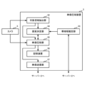
- FIG. 1 is a block diagram showing the configuration of a video processing system according to an embodiment of the present disclosure.
- FIG. 2 is a block diagram showing the configuration of a video compression device according to an embodiment of the present disclosure.
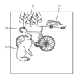
- FIG. 3 is a diagram showing an example of an image included in a video output by a camera.
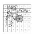
- FIG. 4 is a diagram in which the image shown in FIG. 3 is divided into a plurality of blocks.
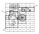
- FIG. 5 is a diagram illustrating an example of a target area including a target object.
- FIG. 6 is a diagram showing another example of a target area including a target object.
- FIG. 7 is a diagram illustrating an example of a target area extraction result by the target area extraction unit.
- FIG. 1 is a block diagram showing the configuration of a video processing system according to an embodiment of the present disclosure.
- FIG. 2 is a block diagram showing the configuration of a video compression device according to an embodiment of the present disclosure.
- FIG. 3 is a diagram showing an example of an image included
- FIG. 8 is a block diagram showing the configuration of a server according to an embodiment of the present disclosure.
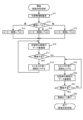
- FIG. 9 is a flowchart illustrating an example of a procedure of processing executed by the video compression device.
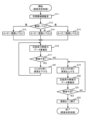
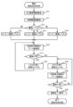
- FIG. 10 is a flowchart showing details of the image quality determination process (step S2 in FIG. 9).
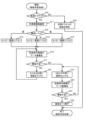
- FIG. 11 is a flowchart showing details of the image quality determination process (step S2 in FIG. 9) according to modification 2.
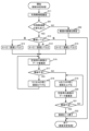
- FIG. 12 is a flowchart showing details of the image quality determination process (step S2 in FIG. 9) according to modification 3.
- FIG. 13 is a flowchart showing details of the image quality determination process (step S2 in FIG. 9) according to modification 4.
- FIG. 14 is a flowchart showing details of the image quality determination process (step S2 in FIG. 9) according to modification 5.
- FIG. 15 is a flowchart showing details of the image quality determination process (step S2 in FIG. 9) according to modification 6.
- the present disclosure has been made in view of these circumstances, and even when the available bandwidth of the transmission path used for communication fluctuates, it realizes the transmission of high-quality video including the attention area.
- the object of the present invention is to provide a video compression method, a video compression device, and a computer program that can perform the following steps.
- a video compression method is a video compression method using a video compression device, and includes a step of extracting a target region including any one of a plurality of target objects from each image forming the video. and determining the image quality of the target area based on the priority of the target object included in the extracted target area and the available bandwidth of the transmission path, and determining the image quality of the determined target area. and transmitting the compressed video to the outside of the video compression device via the transmission path.
- the image quality of the target area can be determined so that the target area containing the target object with higher priority is compressed with higher image quality, and the compressed video is not sent to the transmission path in excess of the available bandwidth. . Therefore, even if the available bandwidth of the transmission path used for communication fluctuates, it is possible to transmit high-quality video including the region of interest.
- the compressed video is used for at least one of remote monitoring and remote control of a moving object, and the priority is determined based on the degree of influence of the moving object on the target object. May be determined.
- a target object that is more affected by a collision with a moving body is set to have a higher priority. Therefore, the more likely the target object is to be affected by a collision, the more possible the remote monitoring or remote control of the moving body will be to avoid the collision. For example, when a moving object approaches a pedestrian who is most likely to be affected by a collision, remote control such as stopping the moving object can be performed.
- the compressed video is used for at least one of remote monitoring and remote control of a moving object, and the priority is determined by the information collected from the target object. It may be determined based on usefulness.
- the image quality of the target area including the traffic signal which is highly useful for remote monitoring or remote control of a moving object, is lowered by that of the roadside area, which is relatively less useful for remote monitoring or controlling of a moving object.
- the image quality can be set higher than the image quality of the target area including the signboard.
- the object including a background region which is an area other than the target region and the target object having a priority lower than a predetermined priority
- the video may be compressed by excluding the area.
- the amount of compressed video data can be kept low by excluding the background region and the target region including target objects of low importance.
- a target area including a highly important target object can be transmitted with high image quality within a range that does not exceed the available bandwidth.
- information of low importance is excluded in advance, so processing can be performed at high speed. Therefore, such compressed video is suitable for real-time processing.
- a predetermined lower limit of image quality at which the presence of the target object can be recognized is set to a lower limit of image quality than a predetermined priority level.
- the image quality may be determined as the image quality of the target area including the target object.
- a target area including a target object of low importance is compressed to a lower limit image quality that allows the presence of the target object to be recognized. Therefore, it is possible to compress the video while keeping the amount of data in the target area including target objects of low importance as low as possible.
- recognition processing is normally performed only on target areas that include target objects of high importance, but if it becomes necessary to re-verify the video, It can be used for verification purposes, such as performing recognition processing on all target regions including target objects with low values. Therefore, such compressed video is suitable for storage in a storage device.
- the compressed video in the step of compressing the video, may be generated to which information on the image quality of the determined target area is added.
- the device that has received the compressed video adds the image quality information added to the video to the decompressed video, so that when a person views the decompressed video, each target area is Image quality can be understood quantitatively rather than intuitively.
- the compressed video in the step of compressing the video, may be generated to which information about the target object included in the target area is added.
- the device that receives the compressed video can efficiently perform processing on the target object (for example, target object recognition processing) based on the target object information added to the video. .
- the image quality of the target area is determined if the available bandwidth changes by a predetermined value or more;
- the image quality of the target area determined when the bandwidth changes by more than the predetermined value may be used as the image quality of the target area when the available bandwidth does not change by more than the predetermined value.
- a video compression device is a video compression device that compresses a video, and extracts a target region including any of a plurality of target objects from each image constituting the video.
- an image quality determination unit that determines the image quality of the target area based on the priority of the target object included in the extracted target area and the available bandwidth of a transmission path; and a video transmitter that transmits the compressed video to the outside of the video compression device via the transmission path.
- This configuration includes a processing unit that corresponds to the characteristic steps in the video compression method described above. Therefore, the video compression device can achieve the same functions and effects as the video compression method described above.
- a computer program is a computer program for causing a computer to function as a video compression device, wherein the computer program selects one of a plurality of target objects from each image constituting a video.
- a target area extraction unit that extracts a target area including a target area; and an image quality that determines the image quality of the target area based on the priority of the target object included in the extracted target area and the available bandwidth of a transmission path.
- the computer can function as the above-mentioned video compression device. Therefore, the computer program can achieve the same functions and effects as the above-described video compression device.
- FIG. 1 is a block diagram showing the configuration of a video processing system according to an embodiment of the present disclosure.
- the video processing system 1 includes a server 2 and a video compression device 3 that are interconnected via a network 4 such as the Internet, and a camera 5 that is connected to the video compression device 3. Although only one video compression device 3 is shown in FIG. 1, a plurality of video compression devices 3 may be connected to the server 2.
- the server 2 and the video compression device 3 are connected to the network 4 wirelessly or by wire.
- the video compression device 3 compresses each time-series image included in the video captured by the camera 5, and sends the compressed image sequence (video) to the server 2.
- the server 2 receives compressed video from the video compression device 3 via the network 4, and decompresses the received video.
- the server 2 processes the decompressed video. For example, the server 2 detects the position of the target object included in the video, the circumscribed area of the target object, etc. by video processing.
- FIG. 2 is a block diagram showing the configuration of a video compression device according to an embodiment of the present disclosure.
- the video compression device 3 is connected to the camera 5 and includes a target area extraction section 32, a bandwidth estimation section 33, an image quality determination section 34, a video compression section 35, a storage device 36, and a video transmission section 37. .
- the video compression device 3 may be configured by a computer system including a processor such as a CPU, and a storage device 36 such as volatile memory or nonvolatile memory. By executing the computer program stored in the storage device 36 on the processor, each of the processing units 32 to 35 and 37 performs its functions.
- a processor such as a CPU
- a storage device 36 such as volatile memory or nonvolatile memory.
- the camera 5 photographs the subject and outputs an image of the subject.
- a video consists of multiple time-series images.
- the camera 5 may be provided inside the video compression device 3 and may be included in the components of the video compression device 3.
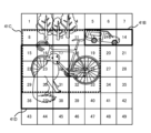
- FIG. 3 is a diagram showing an example of an image included in the video output by the camera 5.
- the image shown in FIG. 3 shows a dog 11, a bicycle 12, a car 13, and a tree 14.
- a video consists of multiple frames of time-series images.
- the target area extraction unit 32 extracts a target area containing any one of a plurality of target objects from each image making up the video.
- the target area extraction unit 32 divides the image into a plurality of blocks, and determines whether each block includes a predetermined target object or not.
- the video compression unit 35 extracts a target area to be compressed with higher image quality than a background area, which is an area other than the target area in the image. Compressing an image with high image quality means that when an image is decompressed and restored, compression processing is performed so that the restored image has high image quality.
- FIG. 4 is a diagram in which the image shown in FIG. 3 is divided into a plurality of blocks.
- an example is shown in which one image is divided into 49 blocks of 7 rows x 7 columns.
- block numbers 1 to 49 are assigned to each block in raster scanning order from the upper left to the lower right of the image.
- the size and number of blocks are not limited to those shown in FIG. 4.
- the types of target objects to be determined by the target area extraction unit 32 are, for example, four types, and the target objects of types A, B, C, and D are a person, a car, a bicycle, and a dog, respectively.
- the target objects of types A to D are also referred to as target objects A to D, respectively.
- Priorities are set for the types of target objects, and types A, B, C, and D have higher priorities in this order. Note that the types of target objects are not limited to four types.
- the target area extraction unit 32 uses a learning model to determine whether or not each of the target objects A to D is included in each of the blocks with block numbers 1 to 49.
- the learning model include CNN (Convolution Neural Network), RNN (Recurrent Neural Network), AutoEncoder, and the like. Deep learning is performed using images of blocks containing various target objects A (hereinafter referred to as "block images"), block images containing target object B, block images containing target object C, and block images containing target object D as training data.
- block images images containing various target objects A
- block images containing target object B block images containing target object B
- block images containing target object C block images containing target object D as training data.
- machine learning methods such as the above, learning of target object A, learning of target object B, learning of target object C, and learning of target object D progresses, and the parameters of the learning model are determined.
- the target area extraction unit 32 inputs an image composed of 49 block images to the learning model.
- the learning model determines whether target objects A, B, C, and D are included in each block, and outputs the determination results.
- the target area extraction unit 32 obtains a determination result from the learning model.
- the target area extraction unit 32 determines the area composed of blocks including the target object A as the target area for compression processing with higher image quality than the background area.
- the target area extraction unit 32 similarly determines the blocks including each of the target objects B to D as target areas.
- FIG. 5 is a diagram showing an example of a target area including a target object.
- FIG. 5 shows target regions 41B to 41D including target objects B to D, respectively.
- the target areas 41B and 41D include blocks within the solid thick frame, and the target area 41C includes blocks within the dashed thick frame.
- the target area 41B is an area that includes the target object B (car), and includes blocks numbered 12 to 14.
- the target area 41C is an area including the target object C (bicycle), and includes blocks numbered 9, 11, 15-19, 22-26, 32, and 33.
- the target area 41D is an area that includes the target object D (dog), and includes blocks numbered 16, 17, 22-24, 29-31, and 36-38.
- FIG. 6 is a diagram showing another example of a target area including a target object.
- FIG. 6 shows target regions 41B to 41D including target objects B to D, respectively.
- the target areas 41B and 41D include blocks within the solid thick frame, and the target area 41C includes blocks within the dashed thick frame.
- the target area 41B is an area that includes the target object B (car), and includes blocks numbered 12 to 14.
- the target area 41C is an area that includes the target object C (bicycle), and includes blocks numbered 8 to 12, 15 to 19, 22 to 26, and 29 to 33.
- the target area 41D is an area that includes the target object D (dog), and includes blocks numbered 15-17, 22-24, 29-31, and 36-38.
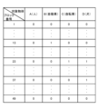
- FIG. 7 is a diagram illustrating an example of a target area extraction result by the target area extraction unit 32.
- block number 1 does not include any of the target objects A to D.
- block No. 13 includes the target object B and does not include the target objects A, C, and D.
- the 23rd block includes target objects C and D, but does not include target objects A and B.
- block number 37 includes the target object D and does not include the target objects A to C.
- block number 49 does not include any of the target objects A to D.
- the bandwidth estimation unit 33 estimates the available bandwidth (the upper limit of the bandwidth available for communication) in the communication path (transmission path) between the video compression device 3 and the server 2. do. For example, the bandwidth estimation unit 33 transmits a test stream to the server 2, receives the returned test stream, measures quality information such as round trip time and packet loss rate, and sets the quality information to a preset value.
- the available bandwidth may be estimated by inputting it into an analytical model.
- the method for estimating the available bandwidth is not limited to the above method. Bandwidth is expressed, for example, as a transmission speed in units of Mbps (Megabits per second).
- the image quality determination unit 34 determines, for each target area extracted by the target area extraction unit 32, the priority of the target object included in the target area and the relationship between the video compression device 3 and the server 2 estimated by the bandwidth estimation unit 33.
- the image quality of the target area is determined based on the available bandwidth of the transmission path between the two.
- the determined image quality is the image quality when compression processing is performed by the video compression section 35.
- the image quality determination unit 34 determines the image quality that satisfies the following two conditions.
- a target area including a relatively high priority target object is compressed with higher image quality or the same image quality than a target area including a relatively low priority target object.
- the video compressed by the video compression unit 35 can be transmitted to the server 2 with a bandwidth equal to or less than the available bandwidth.
- the image quality determination process by the image quality determination unit 34 will be described in detail later.
- the video compression unit 35 changes the image quality for each target area based on the image quality determined by the image quality determination unit 34, and compresses the video (each image) output from the camera 5.
- the compression method is, for example, H. 264/MPEG-4 AVC or H.264/MPEG-4 AVC. 265/MPEG-H HEVC, etc.
- Image quality is expressed, for example, by a quantization parameter QP.
- the video compression unit 35 adds information for identifying the image quality of the target area of each image forming the compressed video to the compressed video. That is, the video compression unit 35 adds information for identifying the image quality of each block of each image forming the compressed video to the compressed video. For example, the video compression unit 35 adds information that associates the block number and the quantization parameter QP to the compressed video.
- the video compression unit 35 adds information for identifying the target object included in the target area of each image forming the compressed video to the compressed video. That is, the video compression unit 35 adds information for identifying the target object included in each block of each image constituting the compressed video to the compressed video. For example, the video compression unit 35 may add to the compressed video, for each block, information that associates the block number with the name information of the target object included in the block. Further, the video compression unit 35 may add to the compressed video, for each block, information in which the block number is associated with a number corresponding to the type of target object included in the block. The video compression unit 35 causes the storage device 36 to store the compressed video to which information has been added.
- the video transmitter 37 acquires the compressed video with information added from the video compressor 35 and transmits the acquired compressed video to the server 2 via the network 4.
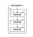
- FIG. 8 is a block diagram showing the configuration of a server according to an embodiment of the present disclosure.
- the server 2 includes a video receiving section 21, a video decompression section 22, and a video processing section 23.
- the server 2 may be configured by a computer system including a processor such as a CPU, and a storage device such as volatile memory or nonvolatile memory. Each of the processing units 21 to 23 performs its functions by executing a computer program stored in a storage device on a processor.
- the video receiving unit 21 receives compressed video from the video compression device 3 via the network 4.
- the video decompression unit 22 restores the original video by decompressing the compressed video received by the video reception unit 21.
- the video processing unit 23 performs predetermined video processing on the decompressed video. For example, the video processing unit 23 detects a circumscribed rectangular area of an object included in each image forming the video. Further, the video processing unit 23 may perform region division processing to extract the region of the object included in the image pixel by pixel. Furthermore, the video processing unit 23 may perform a skeleton estimation process for estimating the skeleton of an object included in the image. The server 2 may transmit the results of video processing by the video processing unit 23 to the video compression device 3.
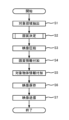
- FIG. 9 is a flowchart illustrating an example of a procedure of processing executed by the video compression device.
- the target area extraction unit 32 determines whether target objects A to D are included in each block in the image output from the camera 5, and extracts a target area that includes each of the target objects A to D (step S1). For example, assume that the target area extraction unit 32 determines that the target object C is included in the block to be determined. In this case, the target area extraction unit 32 extracts the block to be determined as a target area including the target object C. Further, it is assumed that the target area extraction unit 32 determines that the target object A and the target object B are included in the block to be determined.
- the target area extraction unit 32 extracts the block to be determined as a target area including the target object A with a high priority. Further, it is assumed that the target area extraction unit 32 determines that the target object is not included in the block to be determined. In this case, the target area extraction unit 32 extracts the block to be determined as a background area. By performing such target area extraction processing, each block is classified into a target area or a background area that includes any of the target objects A to D.
- the bandwidth estimating unit 33, the image quality determining unit 34, and the video compressing unit 35 determine the image quality of the target area and background area including the target objects A to D (step S2).
- FIG. 10 is a flowchart showing details of the image quality determination process (step S2 in FIG. 9).
- the bandwidth estimation unit 33 estimates the available bandwidth in the communication path between the video compression device 3 and the server 2 (step S11).
- the image quality determining unit 34 determines the level of the available bandwidth estimated by the bandwidth estimating unit 33 (step S12). It is assumed that the level of available bandwidth is determined in advance. For example, the image quality determination unit 34 determines the image quality to be high level when the available bandwidth is equal to or more than a, determines it to be medium level when the available bandwidth is less than a and equal to or more than b, and determines it to be medium level when the available bandwidth is less than b. In this case, it is determined that the level is low.
- a and b are predetermined values, and a>b.
- the image quality determination unit 34 uses the image quality level as the quantization parameter QP when compressing the target region including any of the target objects A to D.
- a quantization parameter QP of 1 is set, and a quantization parameter QP of image quality level 4 is set for the background region (step S13).
- the image quality levels include image quality level 1, image quality level 2, image quality level 3, and image quality level 4 in descending order of image quality.
- Each image quality level is associated with a quantization parameter QP, and the quantization parameter QP is smaller in the order of image quality level 1, image quality level 2, image quality level 3, and image quality level 4.
- the quantization parameters QP of image quality level 1, image quality level 2, image quality level 3, and image quality level 4 are 30, 35, 40, and 50, respectively.
- the image quality determining unit 34 sets the quantization parameter QP of image quality level 2 to the target region including any of the target objects A to D, A quantization parameter QP of image quality level 4 is set in the background area (step S14).
- the image quality determination unit 34 sets a quantization parameter QP of image quality level 3 to the target area including any of the target objects A to D, A quantization parameter QP of image quality level 4 is set in the background area (step S15).
- the video compression unit 35 estimates the amount of data when compressing the image output from the camera 5 based on the quantization parameter QP set in any of steps S13 to S15 (step S16). As an example, for each quantization parameter QP, the video compression unit 35 refers to a data table showing the average amount of data after quantizing and compressing one block image with the quantization parameter QP, and By estimating the data amount of the image after compression, the data amount of one frame of the image after compression is estimated.
- the number of blocks in the target area including target object A, the target area including target object B, the target area including target object C, the target area including target object D, and the background area are NA, NB, NC, ND and NE, and all blocks include 0 or 1 target object.
- the quantization parameter QP when compressing the target region including the target object A, the target region including the target object B, the target region including the target object C, the target region including the target object D, and the background region are respectively, Suppose that they are QPA, QPB, QPC, QPD, and QPE.
- the average data amount of one block image after compressing one block image with quantization parameters QPA, QPB, QPC, QPD, and QPE is DA, DB, DC, DD, and DE.
- the video compression unit 35 estimates that the data amount of one frame of image after compression is (NA ⁇ DA+NB ⁇ DB+NC ⁇ DC+ND ⁇ DD+NE ⁇ DE).
- the video compression unit 35 estimates the amount of compressed video data per second by multiplying the compressed data amount of one frame image by the number of frames included in one second (for example, 30). .
- the image quality determination unit 34 compares the available bandwidth estimated in step S11 with the data amount of the compressed video estimated in step S16, thereby determining whether there is a shortage of bandwidth when transmitting the compressed video to the server 2. It is determined whether or not this occurs (step S17). For example, the image quality determining unit 34 may determine that a bandwidth shortage occurs when the amount of compressed video data per second exceeds the available bandwidth. The image quality determination unit 34 may also determine that a bandwidth shortage occurs when the amount of data obtained by adding a predetermined margin (positive value) to the amount of compressed video data per second exceeds the available bandwidth. . By doing so, it is possible to determine whether or not a band shortage has occurred, taking into consideration the case where the available bandwidth fluctuates.
- the image quality determining unit 34 changes the set quantization parameter QP to a quantization parameter set for the target area including the target object with a low priority.
- the quantization parameter QP is sequentially increased (the image quality is lowered) and the quantization parameter QP is reset (step S18). Thereafter, the processes from step S16 onwards are repeatedly executed.
- the amount by which the quantization parameter QP is changed may be a predetermined value (for example, 2). For example, assume that 30 is set as the quantization parameter QP corresponding to the image quality level 1 for the target objects A to D in step S13.
- the image quality determining unit 34 increases the quantization parameter QP of the target area including the target object D having the lowest priority by 2, changing it to 32.
- the image quality determination unit 34 increases the quantization parameter QP in the order of target objects C, B, and A until the bandwidth shortage is resolved. increase. For example, the image quality determining unit 34 sequentially changes the quantization parameter QP of the target area including each of the target objects C, B, and A to 32.
- the image quality determining unit 34 similarly increases the quantization parameter QP further in the order of target objects D, C, B, and A until the band shortage is resolved. For example, the image quality determining unit 34 sequentially changes the target area including the target objects D, C, B, and A to 34.
- the image quality determination unit 34 applies the set quantization parameter QP to the target area that includes the high priority target object.
- the quantization parameter QP is sequentially lowered (the image quality is increased) starting from the quantization parameter QP, and the quantization parameter QP is reset (step S19).
- the amount by which the quantization parameter QP is changed may be a predetermined value (for example, 1). For example, assume that 30 is set as the quantization parameter QP corresponding to the image quality level 1 for the target objects A to D in step S13.
- the image quality determining unit 34 decreases the quantization parameter QP of the target area including the target object A with the highest priority by 1, changing it to 29.
- the video compression unit 35 estimates the amount of data when compressing the video output from the camera 5 based on the quantization parameter QP set in step S19 (step S20).
- the process in step S20 is similar to the process in step S16.
- step S20 the image quality determining unit 34 transmits the compressed video to the server 2 by comparing the available bandwidth estimated in step S11 and the data amount of the compressed video estimated in step S20. It is determined whether or not a bandwidth shortage will occur at that time (step S21). The process in step S21 is similar to the process in step S17. If it is determined that a band shortage does not occur (NO in step S21), the process returns to step S19.
- the image quality determination unit 34 changes the value of the quantization parameter QP of the target area including the target object that was last processed in step S19 to the value before the change.
- the value is returned to the original value (step S22). For example, if the last process performed in step S19 was the process of changing the quantization parameter QP of the target region including the target object A from 30 to 29, the image quality determining unit 34 Return parameter QP from 29 to 30.
- a quantization parameter QP corresponding to the image quality of the target region and background region including the target objects A to D is determined.
- the video compression unit 35 compresses the video output from the camera 5 based on the set quantization parameter QP (step S3).
- the video compression unit 35 adds information for identifying the image quality of the target area to the compressed video (step S4).
- the video compression unit 35 adds information for identifying the target object included in the target area to the compressed video (step S5).
- the video compression unit 35 writes the compressed video to which these pieces of information have been added into the storage device 36 (step S6).
- the video transmitter 37 receives the compressed video from the video compressor 35 and transmits it to the server 2 (step S7). Note that the process in step S6 and the process in step S7 may be executed in parallel.
- the video compression device 3 performs the processing shown in FIG. 9 on each image forming the video.
- the video compression device 3 shown in FIG. 2 may be, for example, an in-vehicle device installed in a vehicle (mobile object) such as a car or a motorcycle.
- the video compression device 3 compresses the video captured by the camera 5 in front of the vehicle and transmits the compressed video to the server 2 .
- the server 2 decompresses the compressed video, detects the target object by video processing based on the decompressed video, and sends the detection result to the video compression device 3 .
- the on-vehicle device mounted on the vehicle performs at least one of remote monitoring and remote control of the vehicle based on the detection result of the target object by the server 2. That is, the compressed video is used for at least one of remote monitoring and remote control of the mobile object.
- the priority of the target object is determined based on the degree of influence of the moving object on others.
- target object A is a pedestrian
- target object B is a passenger car
- target object C is a truck
- target object D is a traffic light.
- the video compression device 3 may be an in-vehicle device installed in a moving body such as a car.
- the priority of the target object may be determined based on the degree of influence of a moving object upon a collision with the target object, or the usefulness of information collected from the target object. For example, the priority of a target object with a high degree of impact upon collision is set to be equal to or higher than the priority of a target object with high usefulness of information indicated by the target object. Furthermore, the higher the degree of influence of the target object upon collision, the higher the priority is given. Further, the priority level is set higher for a target object whose information is more useful.
- the target object A is a pedestrian, a vehicle, or a traffic signal
- the target object B is a road sign
- the target object C is a barricade or a triangular cone
- the target object D is a store signboard or a road surface.
- the type of target object may be determined according to the size of the object on the image.
- target object A may be a small-sized object
- target object B may be a medium-sized object
- target object C may be a large-sized object. It is assumed that each size is determined in advance. Thereby, the video compression device 3 can perform video compression processing such that the smaller the object, the better the image quality during decompression.
- the target object A may be a large-sized object
- the target object B may be a medium-sized object
- the target object C may be a small-sized object.
- the image quality of the target area can be determined so that the target area containing the target object with higher priority is decompressed with higher image quality, and the compressed video is not sent to the transmission path in excess of the available bandwidth. . Therefore, even if the available bandwidth of the transmission path used for communication fluctuates, it is possible to transmit high-quality video including the region of interest.
- the target area is extracted by determining whether each block that makes up the image contains the target object. Therefore, the target area can be extracted faster than when the target area is extracted from an image that is not divided into blocks.
- the available bandwidth indicates the upper limit of the available bandwidth. Therefore, it is necessary to determine the image quality of the target area so that the target area containing the target object with higher priority is decompressed with higher image quality, and the compressed video is not sent to the transmission path in excess of the available bandwidth. can. Therefore, the amount of compressed video data can be maximized.
- the video compression device 3 when the video compression device 3 is installed on a moving body, the higher the priority is set for the target object that is more affected by the collision of the moving body. Therefore, the more likely the target object is to be affected by a collision, the more the collision can be avoided by remotely monitoring or remotely controlling the moving body. For example, when a moving object approaches a pedestrian who is most likely to be affected by a collision, remote control such as stopping the moving object can be performed.
- the priority level can be set higher for target objects that require higher collision avoidance of moving objects. For example, it is more necessary to avoid collisions with pedestrians than with billboards. Therefore, the image quality of the target area including pedestrians can be set higher than the image quality of the target area including roadside signboards. As a result, even when the available bandwidth is small, it is possible to perform BR>U throw control such as stopping a moving object in order to avoid collision with a pedestrian. Further, it is possible to give a higher priority to a target object whose information obtained from the target object is more useful for remote monitoring or remote control of a moving body. For example, information obtained from traffic lights is more useful for remote monitoring or control of mobile objects than information obtained from billboards. Therefore, the image quality of the target area including the traffic light can be set higher than the image quality of the target area including the roadside signboard.
- the server 2 that has received the compressed video adds the image quality information added to the video to the decompressed video, so that when a person views the decompressed video, the image quality of each target area can be determined. It can be understood quantitatively rather than intuitively.
- the server 2 that has received the compressed video cannot efficiently process the target object (for example, target object recognition processing) in units of blocks based on the target object information added to the video. can.
- ⁇ Modification 1> In the above-described embodiment, all block images constituting a video (image) are compressed. On the other hand, in modification example 1, the video is compressed by excluding the background region, which is a region other than the target region, and the target region, which is composed of a block image including a target object having a lower priority than a predetermined priority.
- the image quality determining unit 34 of the video compression device 3 determines the image quality by compressing the video while excluding the target area including the target object D having the lowest priority and the background area from the compression targets.
- the data amount of the compressed video can be kept low.
- a target area including a highly important target object can be transmitted with high image quality within a range that does not exceed the available bandwidth.
- information of low importance is excluded in advance, so processing can be performed at high speed. Therefore, such compressed video is suitable for real-time processing.
- FIG. 11 is a flowchart showing details of the image quality determination process (step S2 in FIG. 9) according to modification 2.
- the process shown in FIG. 11 includes steps S31 to S33 instead of steps S13 to S15 shown in FIG.
- the processing in steps S11 and S16 to S22 is similar to that shown in FIG.
- the image quality determining unit 34 sets a quantization parameter QP of image quality level 1 to the target region including any of the target objects A to D, A quantization parameter QP of image quality level 4 is set in the background area (step S31).
- the image quality determination unit 34 sets a quantization parameter QP of image quality level 1 to the target area including any of the target objects A to B, A quantization parameter QP of image quality level 2 is set in the target region including any of the target objects C to D, and a quantization parameter QP of image quality level 4 is set in the background region (step S32).
- the image quality determination unit 34 sets the quantization parameter QP of image quality level 1 to the target area that includes the target object A, and sets the quantization parameter QP of the image quality level 1 to the target area that includes the target object B.
- a quantization parameter QP of image quality level 2 is set in the target region
- a quantization parameter QP of image quality level 3 is set in the target region including any of the target objects C to D
- a quantization parameter QP of image quality level 4 is set in the background region.
- QP is set (step S32).
- a quantization parameter QP of image quality level 1 is set in the target region including the target object A in the initial state. Therefore, a target area including a target object with a high priority is compressed with higher image quality than in the above-described embodiment.
- FIG. 12 is a flowchart showing details of the image quality determination process (step S2 in FIG. 9) according to modification 3.
- the process shown in FIG. 12 includes step S41 instead of step S18 shown in FIG.
- the processes in steps S11 to S17 and S19 to S22 are similar to those shown in FIG.
- the image quality determining unit 34 changes the set quantization parameter QP to a quantization parameter set for the target area including the target object with a low priority.
- the quantization parameter QP is sequentially increased (the image quality is lowered), and the quantization parameter QP is reset (step S41).
- the image quality determining unit 34 changes the quantization parameter QP of the target region including the target objects B to D, but does not change the quantization parameter QP of the target region including the target object A.
- the amount by which the quantization parameter QP is changed is a predetermined value (for example, 2).
- the image quality determining unit 34 increases the quantization parameter QP of the target region including the target object D, which has the lowest priority among the target objects B to D, by 2 and changes it to 32.
- the image quality determining unit 34 increases the quantization parameter QP of the target objects C and B in this order until the bandwidth shortage is resolved. For example, the image quality determining unit 34 sequentially changes the quantization parameter QP of the target area including each of the target objects C and B to 32.
- the image quality determining unit 34 similarly increases the quantization parameter QP further in the order of target objects D, C, and B until the band shortage is resolved. For example, the image quality determining unit 34 sequentially changes the target area including the target objects D, C, and B to 34.
- compressed video is transmitted to the server 2 while maintaining a constant image quality regardless of changes in communication bandwidth. I can do it.
- the image quality is determined for each frame of the image forming the video.
- a common image quality may be determined for images of multiple time-series frames.
- FIG. 13 is a flowchart showing details of the image quality determination process (step S2 in FIG. 9) according to modification 4.
- the flowchart shown in FIG. 13 is the flowchart shown in FIG. 10 with steps S51 and S52 added.
- H. 264/MPEG-4 AVC or H.264/MPEG-4 AVC A common image quality is determined for a plurality of images included in a GOP (Group of Pictures), which is a compression unit in a compression method such as H.265/MPEG-H HEVC.
- GOP Group of Pictures
- the image quality determining unit 34 determines whether the image to be compressed is the first picture (I picture) of the GOP (step S51). If the image to be compressed is the first picture (YES in step S51), the processes of steps S11 to S22 are executed, and the image quality of each target area and background area included in the first picture is determined.
- the processing in steps S11 to S22 is similar to that shown in FIG.
- the image quality determining unit 34 sets the image quality of each area included in the first picture as the image quality of each area included in the image to be compressed (step S52). ). According to the fourth modification, the same image quality is maintained in the same area within the same GOP.
- the image quality may be determined not for each GOP but for each predetermined period of time (for example, one minute). That is, the image quality may be determined for the image of the first frame of a predetermined time, and the image quality determined for the image of the first frame may be maintained for the images of the remaining frames.
- the image quality is determined for each frame of the image forming the video.
- the image quality may be determined only when there is a change in the available bandwidth.
- FIG. 14 is a flowchart showing details of the image quality determination process (step S2 in FIG. 9) according to modification 5.
- the flowchart shown in FIG. 14 is the flowchart shown in FIG. 10 with steps S61 and S62 added.
- the image quality determining unit 34 determines whether the available bandwidth estimated by the bandwidth estimating unit 33 has changed (step S61). For example, the image quality determining unit 34 determines that the available bandwidth has changed when the available bandwidth has changed by a predetermined value or more from the available bandwidth that was referenced when determining the image quality last, and in other cases, , it is determined that the available bandwidth has not changed. Note that when compressing the image of the first frame of the video, the image quality determining unit 34 determines that the available bandwidth has changed.
- steps S11 to S22 are executed, and the image quality of each region included in the image to be compressed is determined.
- the processing in steps S11 to S22 is similar to that shown in FIG.
- the image quality determining unit 34 determines that the available bandwidth has changed at the end as the image quality of each area included in the compression target image.
- the image quality of each area determined when the image quality is determined is set (step S62).
- modification 5 if there is little change in the available bandwidth, there is no need to change the amount of compressed video data. Therefore, by not changing the image quality, it is possible to prevent the data amount of the compressed video from changing. This eliminates the need to unnecessarily perform image quality determination processing.
- the lower limit image quality (hereinafter referred to as "limit image quality") at which the presence of a predetermined target object can be recognized is set as the image quality of a target area that includes a target object with a priority lower than a predetermined priority. do.
- the value of the quantization parameter QP indicating the critical image quality is 50.
- the maximum value of the quantization parameter QP is 51.
- FIG. 15 is a flowchart showing details of the image quality determination process (step S2 in FIG. 9) according to modification 6.
- the flow chart shown in FIG. 15 adds step S71 to the flow chart shown in FIG. 10, uses steps S72, S73, and S74 instead of steps S13, S14, and S15, and uses steps S75 and S76 instead of steps S18 and S19. This is what I used.
- the processing in steps S11, S12, S16, S17, and S20 to S22 is the same as that shown in FIG.
- the image quality determination unit 34 sets a limit image quality to the image quality of the target area that includes a target object (that is, target object D) that has a lower priority than the target object of type C (step S71).
- the image quality determination unit 34 uses the image quality level as the quantization parameter QP when compressing the target region including any of the target objects A to C.
- a quantization parameter QP of 1 is set (step S72).
- the image quality determination unit 34 sets the quantization parameter QP of image quality level 2 to the target region including any of the target objects A to C ( Step S73).
- the image quality determining unit 34 sets the quantization parameter QP of image quality level 3 to the target region including any of the target objects A to C ( Step S74).
- the image quality determination unit 34 uses the quantization parameter QP set for the target area including target objects A to C to target objects with lower priority.
- the quantization parameter QP set for the target region including the target area is increased in order (the image quality is lowered), and the quantization parameter QP is reset (step S75). This process is similar to the process in step S41 in FIG.
- the image quality determination unit 34 uses the quantization parameter QP set for the target area including the target objects A to C as the target object with a high priority.
- the quantization parameter QP is sequentially lowered (increasing the image quality) starting from the quantization parameter QP set for the target region including the target region, and the quantization parameter QP is reset (step S76).
- the amount by which the quantization parameter QP is changed is a predetermined value (for example, 1).
- the target area including the target object D of low importance is compressed so that the image quality is at the lower limit where the existence of the target object D can be recognized. Therefore, the video can be compressed while keeping the amount of data in the target area including the target object D of low importance as low as possible.
- recognition processing is normally performed only on the target area that includes the highly important target objects A to C, but if it becomes necessary to re-verify the video, , it can be used for verification purposes, such as performing recognition processing on a target area that includes the target object D of low importance. Therefore, such compressed video is suitable for storage in a storage device.
- a part or all of the components constituting each of the above devices may be composed of one or more semiconductors such as a system LSI.
- the above-mentioned computer program may be recorded on a computer-readable nonvolatile recording medium, such as an HDD, CD-ROM, or semiconductor memory, and distributed. Furthermore, the computer program may be transmitted and distributed via telecommunications lines, wireless or wired communication lines, networks typified by the Internet, data broadcasting, and the like. Furthermore, each of the above devices may be realized by multiple computers or multiple processors.
- a computer-readable nonvolatile recording medium such as an HDD, CD-ROM, or semiconductor memory
- the computer program may be transmitted and distributed via telecommunications lines, wireless or wired communication lines, networks typified by the Internet, data broadcasting, and the like.
- each of the above devices may be realized by multiple computers or multiple processors.
- each of the above devices may be provided by cloud computing.
- some or all of the functions of each device may be realized by a cloud server.
- at least a portion of the above embodiment and the above modification may be combined arbitrarily.
- Video processing system 2 Server 3
- Video compression device 4 Network 5
- Video reception section 22 Video decompression section 23
- Video processing section 32 Target area extraction section 33
- Bandwidth estimation section 34 Image quality determination section 35
- Video Compression unit 36 Storage device 37
Landscapes
- Engineering & Computer Science (AREA)
- Multimedia (AREA)
- Signal Processing (AREA)
- Compression Or Coding Systems Of Tv Signals (AREA)
Priority Applications (1)
| Application Number | Priority Date | Filing Date | Title |
|---|---|---|---|
| JP2024514865A JPWO2023199696A1 (cg-RX-API-DMAC7.html) | 2022-04-11 | 2023-03-17 |
Applications Claiming Priority (2)
| Application Number | Priority Date | Filing Date | Title |
|---|---|---|---|
| JP2022065258 | 2022-04-11 | ||
| JP2022-065258 | 2022-04-11 |
Publications (1)
| Publication Number | Publication Date |
|---|---|
| WO2023199696A1 true WO2023199696A1 (ja) | 2023-10-19 |
Family
ID=88329367
Family Applications (1)
| Application Number | Title | Priority Date | Filing Date |
|---|---|---|---|
| PCT/JP2023/010673 Ceased WO2023199696A1 (ja) | 2022-04-11 | 2023-03-17 | 映像圧縮方法、映像圧縮装置、及びコンピュータプログラム |
Country Status (2)
| Country | Link |
|---|---|
| JP (1) | JPWO2023199696A1 (cg-RX-API-DMAC7.html) |
| WO (1) | WO2023199696A1 (cg-RX-API-DMAC7.html) |
Citations (4)
| Publication number | Priority date | Publication date | Assignee | Title |
|---|---|---|---|---|
| JPH10112856A (ja) * | 1996-10-04 | 1998-04-28 | Agency Of Ind Science & Technol | 画像伝送装置および方法 |
| JP2012244437A (ja) * | 2011-05-19 | 2012-12-10 | Canon Inc | 画像処理装置、画像処理方法 |
| JP2013168739A (ja) * | 2012-02-14 | 2013-08-29 | Hitachi Ltd | 画像処理システム、及び、画像処理方法 |
| WO2018037890A1 (ja) * | 2016-08-23 | 2018-03-01 | 日本電気株式会社 | 映像処理装置、映像処理方法及びプログラムを記憶する記憶媒体 |
-
2023
- 2023-03-17 JP JP2024514865A patent/JPWO2023199696A1/ja active Pending
- 2023-03-17 WO PCT/JP2023/010673 patent/WO2023199696A1/ja not_active Ceased
Patent Citations (4)
| Publication number | Priority date | Publication date | Assignee | Title |
|---|---|---|---|---|
| JPH10112856A (ja) * | 1996-10-04 | 1998-04-28 | Agency Of Ind Science & Technol | 画像伝送装置および方法 |
| JP2012244437A (ja) * | 2011-05-19 | 2012-12-10 | Canon Inc | 画像処理装置、画像処理方法 |
| JP2013168739A (ja) * | 2012-02-14 | 2013-08-29 | Hitachi Ltd | 画像処理システム、及び、画像処理方法 |
| WO2018037890A1 (ja) * | 2016-08-23 | 2018-03-01 | 日本電気株式会社 | 映像処理装置、映像処理方法及びプログラムを記憶する記憶媒体 |
Also Published As
| Publication number | Publication date |
|---|---|
| JPWO2023199696A1 (cg-RX-API-DMAC7.html) | 2023-10-19 |
Similar Documents
| Publication | Publication Date | Title |
|---|---|---|
| EP3722992B1 (en) | System and method for pre-processing images captured by a vehicle | |
| WO2021164216A1 (zh) | 一种视频编码方法、装置、设备及介质 | |
| WO2022067656A1 (zh) | 一种图像处理方法及装置 | |
| JP6392572B2 (ja) | 画像受信装置、画像伝送システムおよび画像受信方法 | |
| CN114679607A (zh) | 一种视频帧率控制方法、装置、电子设备及存储介质 | |
| CN105391972A (zh) | 图像通信设备、图像发送设备和图像接收设备 | |
| Chan et al. | Influence of AVC and HEVC compression on detection of vehicles through Faster R-CNN | |
| WO2023193629A1 (zh) | 区域增强层的编解码方法和装置 | |
| EP3975133A1 (en) | Processing of images captured by vehicle mounted cameras | |
| US20260065028A1 (en) | Entropy estimation method and apparatus for image compression | |
| US12185029B2 (en) | Apparatus and method for transmitting images and apparatus and method for receiving images | |
| KR20210055257A (ko) | 사고 영상 분석 시스템 및 이를 이용한 분석 방법 | |
| JP2008048243A (ja) | 画像処理装置、画像処理方法および監視カメラ | |
| Peled et al. | Automative video compression for remote driving via safety considerations | |
| CN114157870A (zh) | 编码方法、介质及电子设备 | |
| CN113727073A (zh) | 一种基于云计算实现车载视频监控的方法及系统 | |
| CN119484883A (zh) | 带宽受限条件下的视频窄带传输方法、装置和电子设备 | |
| WO2024198897A1 (zh) | 一种视频传输方法、装置、存储介质和系统 | |
| WO2023132163A1 (ja) | 映像圧縮方法、映像圧縮装置、コンピュータプログラム、及び映像処理システム | |
| Kajak | Impact of video compression on the performance of object detection algorithms in automotive applications | |
| JP2021034983A (ja) | 映像ストリームに影響した外的要因情報を推定するプログラム、サーバ、システム、端末及び方法 | |
| CN117692675A (zh) | 视频流智能信息叠加方法及设备、视频流解码方法及设备 | |
| CN118470591A (zh) | 一种视频分析边缘计算加速方法、装置、介质及产品 | |
| WO2024077799A1 (en) | Method and system for image data processing | |
| JP7143263B2 (ja) | 符号化パラメータを用いて対象識別位置を決定する対象識別方法、装置及びプログラム |
Legal Events
| Date | Code | Title | Description |
|---|---|---|---|
| 121 | Ep: the epo has been informed by wipo that ep was designated in this application |
Ref document number: 23788118 Country of ref document: EP Kind code of ref document: A1 |
|
| WWE | Wipo information: entry into national phase |
Ref document number: 2024514865 Country of ref document: JP |
|
| NENP | Non-entry into the national phase |
Ref country code: DE |
|
| 122 | Ep: pct application non-entry in european phase |
Ref document number: 23788118 Country of ref document: EP Kind code of ref document: A1 |