WO2023199588A1 - 制御装置、制御方法及びプログラム - Google Patents
制御装置、制御方法及びプログラム Download PDFInfo
- Publication number
- WO2023199588A1 WO2023199588A1 PCT/JP2023/004834 JP2023004834W WO2023199588A1 WO 2023199588 A1 WO2023199588 A1 WO 2023199588A1 JP 2023004834 W JP2023004834 W JP 2023004834W WO 2023199588 A1 WO2023199588 A1 WO 2023199588A1
- Authority
- WO
- WIPO (PCT)
- Prior art keywords
- control
- forgetting
- amount
- manipulated variable
- value
- Prior art date
- Legal status (The legal status is an assumption and is not a legal conclusion. Google has not performed a legal analysis and makes no representation as to the accuracy of the status listed.)
- Ceased
Links
Images





Classifications
-
- G—PHYSICS
- G05—CONTROLLING; REGULATING
- G05B—CONTROL OR REGULATING SYSTEMS IN GENERAL; FUNCTIONAL ELEMENTS OF SUCH SYSTEMS; MONITORING OR TESTING ARRANGEMENTS FOR SUCH SYSTEMS OR ELEMENTS
- G05B15/00—Systems controlled by a computer
- G05B15/02—Systems controlled by a computer electric
-
- G—PHYSICS
- G05—CONTROLLING; REGULATING
- G05B—CONTROL OR REGULATING SYSTEMS IN GENERAL; FUNCTIONAL ELEMENTS OF SUCH SYSTEMS; MONITORING OR TESTING ARRANGEMENTS FOR SUCH SYSTEMS OR ELEMENTS
- G05B13/00—Adaptive control systems, i.e. systems automatically adjusting themselves to have a performance which is optimum according to some preassigned criterion
- G05B13/02—Adaptive control systems, i.e. systems automatically adjusting themselves to have a performance which is optimum according to some preassigned criterion electric
- G05B13/04—Adaptive control systems, i.e. systems automatically adjusting themselves to have a performance which is optimum according to some preassigned criterion electric involving the use of models or simulators
-
- G—PHYSICS
- G05—CONTROLLING; REGULATING
- G05B—CONTROL OR REGULATING SYSTEMS IN GENERAL; FUNCTIONAL ELEMENTS OF SUCH SYSTEMS; MONITORING OR TESTING ARRANGEMENTS FOR SUCH SYSTEMS OR ELEMENTS
- G05B13/00—Adaptive control systems, i.e. systems automatically adjusting themselves to have a performance which is optimum according to some preassigned criterion
- G05B13/02—Adaptive control systems, i.e. systems automatically adjusting themselves to have a performance which is optimum according to some preassigned criterion electric
- G05B13/04—Adaptive control systems, i.e. systems automatically adjusting themselves to have a performance which is optimum according to some preassigned criterion electric involving the use of models or simulators
- G05B13/042—Adaptive control systems, i.e. systems automatically adjusting themselves to have a performance which is optimum according to some preassigned criterion electric involving the use of models or simulators in which a parameter or coefficient is automatically adjusted to optimise the performance
-
- G—PHYSICS
- G05—CONTROLLING; REGULATING
- G05B—CONTROL OR REGULATING SYSTEMS IN GENERAL; FUNCTIONAL ELEMENTS OF SUCH SYSTEMS; MONITORING OR TESTING ARRANGEMENTS FOR SUCH SYSTEMS OR ELEMENTS
- G05B13/00—Adaptive control systems, i.e. systems automatically adjusting themselves to have a performance which is optimum according to some preassigned criterion
- G05B13/02—Adaptive control systems, i.e. systems automatically adjusting themselves to have a performance which is optimum according to some preassigned criterion electric
- G05B13/04—Adaptive control systems, i.e. systems automatically adjusting themselves to have a performance which is optimum according to some preassigned criterion electric involving the use of models or simulators
- G05B13/048—Adaptive control systems, i.e. systems automatically adjusting themselves to have a performance which is optimum according to some preassigned criterion electric involving the use of models or simulators using a predictor
Definitions
- the present disclosure relates to a control device, a control method, and a program.
- Control devices such as temperature control devices, PLCs (Programmable Logic Controllers), DCS (Distributed Control Systems), and control devices implemented on personal computers and embedded control devices are widely used in industry.
- control methods that aim to make the controlled variable of a controlled object follow a target value
- PID Proportional-Integral-Differential
- model predictive control model predictive control
- internal model control model predictive control
- LQG Linear-Quadratic-Gaussian
- Model predictive control is a method of obtaining a desired response by sequentially performing optimization calculations using a state space model of the controlled object and a future time response model, and is widely used in industry (for example, Patent Document 1).
- Patent Document 1 For example, as an industrial application of standard model predictive control that executes a numerical optimization algorithm online, application to control of air conditioning systems, etc. is known (for example, Patent Document 1).
- a control device determines a new manipulated variable based on a corrected target deviation, which is the difference between a target value and a predicted value of the controlled variable according to changes in the past manipulated variable up to the present.
- a corrected target deviation which is the difference between a target value and a predicted value of the controlled variable according to changes in the past manipulated variable up to the present.
- control device determines the manipulated variable by predicting the future based on a model of the plant to be controlled, and learns model parameters included in a plant response function representing the model online (for example, Patent Document 4). .
- Model predictive control generally performs precise control by predicting the future based on a model of the controlled object, so it is said that it can achieve higher control performance compared to control that does not have a model of the controlled object, such as PID control. It is being said.
- the model used for model predictive control is significantly different from the control target, or if unknown disturbances that are not included in the input/output relationship assumed in advance occur, future predictions may differ greatly from reality. The problem is that the control performance may deteriorate as a result.
- the present disclosure has been made in view of the above points, and aims to provide a technique for suppressing a decline in control performance in model predictive control.
- a control device is a control device that outputs a manipulated variable for a controlled object and causes the controlled variable of the controlled object to follow a target value, wherein the difference between the target value and the current controlled variable is
- a target deviation calculation unit configured to calculate a certain target deviation
- a forgetting unit configured to asymptotically forget a predicted value of a past controlled variable by a plant response function that is a function representing a plant response model of the controlled object.
- a predicted time series storage unit with forgetting configured to store a predicted time series, and a predicted value of the controlled variable after a predetermined look-ahead length has elapsed and correction based on the target deviation based on the predicted time series with forgetting.
- a corrected target deviation calculation unit configured to calculate a target deviation; and an operation change configured to calculate a change amount of the manipulated variable based on the corrected target deviation and a predetermined control gain.
- a manipulated variable calculation unit configured to calculate a new manipulated variable by adding the amount of change in the manipulated variable to the manipulated variable.
- a technology is provided that suppresses the decline in control performance in model predictive control.
- FIG. 2 is a diagram showing an example of a hardware configuration of a control device according to a first embodiment.
- FIG. 2 is a diagram showing an example of a functional configuration of a control device according to a first embodiment.
- FIG. 6 is a diagram for explaining an example of the operation of a correction target deviation calculating section.
- FIG. 3 is a diagram for explaining an example of updating a predicted time series storage unit with forgetting.
- FIG. 6 is a diagram for explaining an example of the operation of an operation change amount calculating section. It is a figure showing an example of functional composition of a control device concerning a second embodiment.
- FIG. 3 is a diagram showing a step response of a controlled plant in Example 1.
- FIG. 3 is a diagram showing a step response of a plant response model in Example 1.
- FIG. 6 is a diagram showing a control response when forgetting is not performed in Example 1.
- FIG. 6 is a diagram showing a control response when forgetting is performed in Example 1.
- 7 is a diagram showing a step response of a plant to be controlled and a plant response model in Example 2.
- FIG. 7 is a diagram showing target values and disturbances in Example 2.
- FIG. 7 is a diagram showing a control response when forgetting is performed in Example 2.
- FIG. 7 is a diagram showing a control response when forgetting is performed in Example 2.
- a control device 10 which calculates a manipulated variable for causing a controlled variable to follow a target value by model predictive control when an arbitrary plant is set as a control target and its target value is given.
- a forgetting coefficient is introduced to asymptotically forget the control amount predicted in the past by a model of the plant to be controlled (hereinafter also referred to as a plant response model). This suppresses the adverse effect on control due to the failure of the future prediction of the plant response model, and as a result, it is possible to suppress the decline in control performance due to the failure of the future prediction.
- control device 10 may be realized by, for example, a PC (personal computer), a general-purpose server, etc., or may be realized by an edge device (PLC, DCS, etc.) that has poor computational resources compared to those devices. may be done.
- PC personal computer
- PLC edge device
- DCS DCS
- the control device 10 calculates an operation amount for the controlled plant 20 based on an arbitrary target value r, a controlled variable y indicating the state of the controlled plant 20, a plant response model of the controlled plant 20, etc. Calculate u. Then, the control device 10 according to the present embodiment measures the controlled variable y of the controlled plant 20 according to this manipulated variable u, and measures the next manipulated variable based on the target value r, the controlled variable y, the plant response model, etc. Calculate u. In this way, the control device 10 according to the present embodiment repeatedly calculates the manipulated variable u to make the controlled variable y follow the target value r during online execution (that is, while controlling the controlled plant 20). .
- control amount y includes, for example, the temperature of the controlled plant 20, and the target value r includes, for example, a set temperature.
- the controlled variable y and the target value r are not limited to the temperature and the set temperature, but any controlled variable in the controlled plant 20 and a target value of the controlled variable can be used.
- FIG. 1 is a diagram showing an example of the hardware configuration of a control device 10 according to the first embodiment.
- the control device 10 includes an input device 11, a display device 12, an external I/F 13, a communication I/F 14, a processor 15, and a memory device 16. Each of these pieces of hardware is communicably connected via a bus 17 .
- the input device 11 is, for example, a keyboard, a mouse, a touch panel, various physical buttons, etc.
- the display device 12 is, for example, a display, a display panel, or the like. Note that the control device 10 may not include at least one of the input device 11 and the display device 12, for example.
- the external I/F 13 is an interface with external devices such as the recording medium 13a.
- the recording medium 13a include a CD (Compact Disc), a DVD (Digital Versatile Disk), an SD memory card (Secure Digital memory card), and a USB (Universal Serial Bus) memory card.
- the communication I/F 14 is an interface for connecting the control device 10 to a communication network.
- the processor 15 is, for example, various arithmetic devices such as a CPU (Central Processing Unit) or an MPU (Micro-Processing Unit).
- the memory device 16 is, for example, various storage devices such as an SSD (Solid State Drive), a RAM (Random Access Memory), a ROM (Read Only Memory), and a flash memory.
- control device 10 may have another hardware configuration.
- the control device 10 may include multiple processors 15 and multiple memory devices 16, or may include various hardware other than the illustrated hardware.
- FIG. 2 is a diagram showing an example of the functional configuration of the control device 10 according to the first embodiment.
- the control device 10 includes a measurement section 101, a difference device 102, an operation amount update section 103, and a timer 104. These are realized, for example, by one or more programs installed in the control device 10 causing the processor 15 or the like to execute the processing. Further, the control device 10 according to the present embodiment includes a predicted time series storage unit 105 with forgetting. The predicted time series storage unit 105 with forgetting is realized, for example, by the memory device 16 included in the control device 10.
- the measuring unit 101 measures (observes) the controlled variable y of the controlled plant 20 every control cycle Tc . Then, the measurement unit 101 outputs the latest value of the measured control amount y as the current control amount value y0 .
- the control amount y of the controlled plant 20 is determined according to the manipulated variable u and the disturbance v. Examples of the disturbance v include a decrease or increase in outside temperature when the control amount y is temperature.
- the measurement unit 101 acquires (observes) the manipulated variable u output from the manipulated variable update unit 103 every control cycle Tc , and converts the latest value of the acquired manipulated variable u into the manipulated variable current value u 0 Output as .
- the differentiator 102 outputs the difference (deviation) between the target value r and the current control amount value y 0 as the target deviation e 0 .
- the manipulated variable update unit 103 calculates the manipulated variable u for the controlled plant 20 every control cycle Tc .
- the operation amount update section 103 includes a corrected target deviation calculation section 111, an operation change amount calculation section 112, and an adder 113.
- the corrected target deviation calculation unit 111 calculates a plant response function ⁇ S ⁇ (t) ⁇ , a target deviation e 0 (t), and an operation change amount time series ⁇ which is time series data of the change amount du of the past operation amount u. du(t) ⁇ , the read-ahead length Tp , and the forgetting coefficient ⁇ , a corrected target deviation e * (t) that corrects the target deviation e 0 (t) is calculated.
- the corrected target deviation calculation unit 111 calculates a prediction time series (a time series of predicted values of the control amount y up to a certain time in the future, which is a past prediction) stored in the prediction time series storage unit 105 with forgetting.
- the plant response function ⁇ S ⁇ (t) ⁇ is a function including the model parameter ⁇ , and is a plant response model of the plant 20 to be controlled.
- the plant response function S ⁇ ( ⁇ ) for example, a function that inputs time t and outputs a step response of the controlled plant 20 can be used. Note that details of the method for calculating the corrected target deviation e * (t) will be described later.
- the operation change amount calculation unit 112 calculates the operation change amount du(t) based on the corrected target deviation e * (t) and the control gain kI .
- the operation change amount calculation unit 112 calculates and outputs the operation change amount du(t) in the order of, for example, du(t-3T c ), du(t-2T c ), and du(t-T c ).
- the operation change amount du is the amount by which the operation amount u changes every control cycle Tc .
- the adder 113 adds the current manipulated variable value u 0 outputted from the measuring section 101 and the manipulated variable amount du outputted from the manipulated variable amount calculation section 112 to calculate a new manipulated variable u. Then, the adder 113 outputs this new manipulated variable u to the controlled plant 20.
- the timer 104 operates the measuring section 101 and the manipulated variable updating section 103 every control period Tc . That is, the timer 104 operates as an operation trigger for the measuring section 101 and the manipulated variable updating section 103 every control cycle Tc .
- the control period Tc is a period for controlling the controlled plant 20, and its value is set in advance.
- the predicted time series with forgetting storage unit 105 stores a predicted time series (a time series of predicted values of the control amount y up to a certain time in the future, which is a time series of predicted values of the control amount y up to a certain time in the future, and which is a time series of predicted values of the control amount y up to a certain time in the future), which is a time series of predicted values of the control amount y up to a certain time in the future. time series of predicted values).
- the control device 10 allows the measuring unit 101 to measure the controlled variable y and the manipulated variable u, and the manipulated variable updating unit 103 to perform a new operation. By sequentially repeating the calculation of the quantity u, the plant 20 to be controlled can be controlled.
- FIG. 3 is a diagram for explaining an example of the operation of the corrected target deviation calculating section 111.
- the corrected target deviation calculation unit 111 calculates the plant response function ⁇ S ⁇ (t) ⁇ , the target deviation e 0 (t), the operation variation time series ⁇ du(t) ⁇ , and the
- the value that the control amount is predicted to change after T p has elapsed from the current time t due to the past operation change amount is calculated as a look-ahead response correction value y, taking into account the forgetting of past predicted values. Calculated as n (t).
- the corrected target deviation calculation unit 111 outputs a corrected target deviation e * (t) that is obtained by correcting the target deviation e 0 (t) using the look-ahead response correction value y n (t).
- the look-ahead response correction value y n (t) is calculated using the predicted time series stored in the predicted time series storage unit 105 with forgetting. A specific example of the calculation method will be described below.
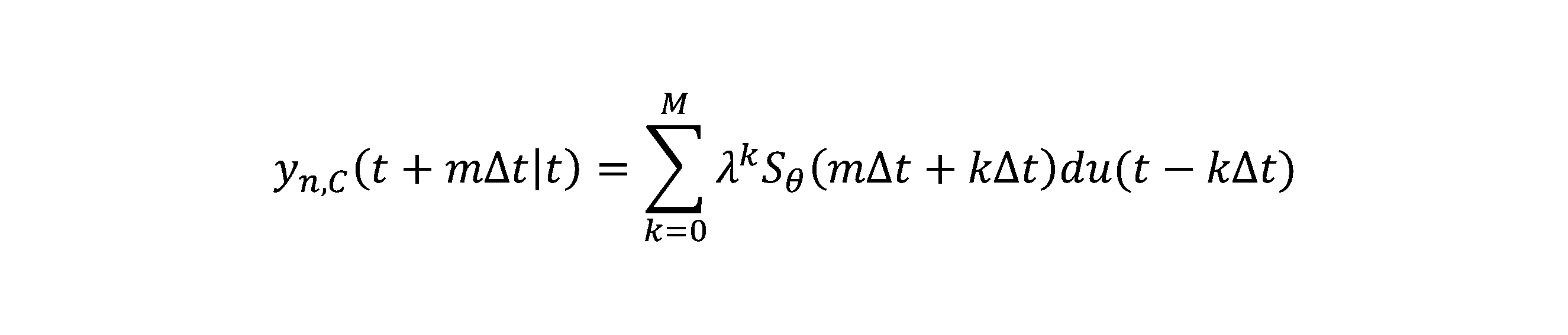
- the predicted value of the control amount y at time s predicted at time t is defined as a generalized predicted value y n,C (s
- the predicted time series storage unit 105 stores generalized predicted values y n,C (s
- the predicted time series storage unit 105 stores y n,C (t- ⁇ t
- the predicted response response value y n,A (t) which is the predicted value of the control amount y at the look-ahead time t+T p based only on the operation change amount time series ⁇ du(t) ⁇
- y n,A (t) y n,C (t+T p
- the predicted time series storage unit 105 with forgetting is updated by the corrected target deviation calculation unit 111 every time a new operation change amount du(t) is calculated by the operation change amount calculation unit 112. Therefore, by using the prediction time series storage unit 105 with forgetting, the corrected target deviation e * (t) can be calculated with less calculation and memory than recalculating the generalized prediction value y n,C every time. can be calculated.
- a specific example of a method for updating the predicted time series storage unit 105 with forgetting will be described below.
- t) at m ⁇ t ahead predicted at time t is expressed as follows.
- n 0, 1, . . . , N 1 .
- t+ ⁇ t) predicted at time t+ ⁇ t ahead of m ⁇ t is y n,C (t+ ⁇ t+m ⁇ t
- t+ ⁇ t) S ⁇ (m ⁇ t)du(t+ ⁇ t)+ ⁇ y n,C (t+(m+1) ⁇ t
- t+ ⁇ t) is the operational change at time t+ ⁇ t with respect to the generalized predicted value y n,C ahead of (m+1) ⁇ t predicted at time t multiplied by the forgetting coefficient ⁇ .
- the predicted time series with forgetting storage unit 105 at time t+ ⁇ t is updated using the predicted time series stored in the predicted time series with forgetting storage unit 105 at time t and the operation change amount du(t+ ⁇ t). be able to.
- the predicted time series with forgetting storage unit 105 at time t+ ⁇ t is updated using the predicted time series stored in the predicted time series with forgetting storage unit 105 at time t and the operation change amount du(t+ ⁇ t).
- FIG. 4 is a diagram for explaining an example of updating the predicted time series storage unit 105 with forgetting.
- the predicted time series storage unit 105 with forgetting at time t+ ⁇ t stores y n,C (t
- t+ ⁇ t) is stored.
- t+ ⁇ t) can be calculated as a value obtained by multiplying y n,C (t
- t+ ⁇ t) is calculated as the value obtained by multiplying y n,C (t+ ⁇ t
- t+ ⁇ t) is expressed as ⁇ y n,C (t+(m+1) ⁇ t
- t+ ⁇ t) is calculated according to Equation 1 above.
- the predicted time series storage unit 105 forgets the predicted value at time t using the forgetting coefficient ⁇ , and adds the influence of the new operation change amount du(t+ ⁇ t) to the predicted value at time t+ ⁇ t. Updated.
- FIG. 5 is a diagram for explaining an example of the operation of the operation change amount calculation unit 112.
- the operation change amount calculation unit 112 calculates the control gain kI for the corrected target deviation e * (t).
- the operation change amount calculation unit 112 sets du max as the operation change amount du(t). .
- the operation change amount calculation unit 112 sets du min to the operation change amount du(t). do.
- the control device 10 repeatedly calculates the manipulated variable u for causing the controlled variable y to follow the target value r and estimates the model parameters of the plant response model during online execution. Thereby, for example, after the controlled plant 20 starts operating, it becomes possible to estimate model parameters that follow seasonal changes in plant characteristics, aging deterioration, and other changes over time.
- FIG. 6 is a diagram showing an example of the functional configuration of the control device 10 according to the second embodiment.
- the control device 10 includes the measuring section 101, the differentiator 102, the operation amount updating section 103, the timer 104, and the predicted time series storage section 105 with forgetting described in the first embodiment.
- it has a model parameter estimator 106.
- the model parameter estimating unit 106 is realized, for example, by one or more programs installed in the control device 10 causing the processor 15 or the like to execute the process.
- the model parameter estimating unit 106 inputs the current value of the controlled variable y 0 (t) and the current value of the manipulated variable u 0 (t) for each control period T c , and calculates the model of the plant response function ⁇ S ⁇ (t) ⁇ .
- the parameter estimate ⁇ est is calculated and output.
- an autoregressive moving average model (ARMA) is used as the plant response function ⁇ S ⁇ (t) ⁇ .
- ARMA autoregressive moving average model
- N and M are preset integers of 1 or more.
- model parameter ⁇ is expressed as follows.
- each element of the model parameter ⁇ is each coefficient of the ARMA model.
- the above ARMA model is just an example, and may be a model that takes into consideration the disturbance v at L points in the past (L is a preset integer of 1 or more), for example. Further, the present invention is not limited to the ARMA model, and for example, an ARMAX model or the like may be used as the plant response function ⁇ S ⁇ (t) ⁇ .
- the timer 104 operates the measuring section 101, the manipulated variable updating section 103, and the model parameter estimating section 106 every control period Tc . That is, the timer 104 also operates as an operation trigger for the model parameter estimation unit 106 every control period Tc .
- the control device 10 can measure the controlled variable y and the manipulated variable u by the measuring section 101 and the model parameter ⁇ by the model parameter estimating section 106 for each control cycle Tc .
- Example 1 of the control device 10 according to the second embodiment will be described below. This example shows the effectiveness of the control device 10 according to the second embodiment when there is an error between the controlled plant 20 and the plant response model.
- y(k) ⁇ 1 y(k-1)+ ⁇ 2 y(k-2)+ ⁇ 3 u(k)+ ⁇ 4 u(k-1)+ ⁇ 5 u(k-2)
- the state vector is defined below.
- model parameter ⁇ is defined below.
- FIG. 7 shows the step response of the controlled plant 20 in this embodiment.
- FIG. 8 shows the step response of the plant response model in this example. 7 and 8 both show changes in the controlled variable y when the manipulated variable u changes in unit steps at time 0. As shown in FIGS. 7 and 8, the time constant of the plant response model is longer than that of the controlled plant 20, and it can be said that an error (model error) has occurred in the plant response model.
- the control device 10 according to the second embodiment or the control device 10 according to the first embodiment may be used when the model parameter ⁇ does not change over time and is a fixed value) takes forgetting into account. It can be said that the effect of the prediction time series makes it possible to suppress the negative impact on control caused by incorrect predictions due to model errors.
- Example 2 of the control device 10 according to the second embodiment will be described below. This example shows the effectiveness of the control device 10 according to the second embodiment when an unknown disturbance is applied to the controlled plant 20. Note that the settings are the same as in Example 1, unless otherwise specified.
- FIG. 11 shows the step response of the plant 20 to be controlled and the plant response model in this embodiment.
- FIG. 11 shows the change in the controlled variable y when the manipulated variable u changes in unit steps at time 0. In this embodiment, it is assumed that the plant 20 to be controlled and the plant response model match.
- the target value r and disturbance v in this example are shown in FIG. As shown in FIG. 12, in this example, it is assumed that an unknown disturbance v is applied in a stepwise manner at time 500.
- the control device 10 according to the second embodiment or the control device 10 according to the first embodiment may be used when the model parameter ⁇ does not change over time and is a fixed value) takes forgetting into consideration. It can be said that the effect of the prediction time series makes it possible to suppress the adverse effects on control caused by prediction errors due to unknown disturbances.
- the control device 10 according to the second embodiment (or, if the model parameter ⁇ is a fixed value without changing over time, the control device 10 according to the first embodiment may be used. ) can suppress the adverse effects caused by incorrect future predictions in model predictive control, and as a result, can suppress a decline in control performance.
- the control device 10 according to the first embodiment asymptotically forgets predictions made in the past, it is possible to suppress the adverse effect on control caused by the prediction of model predictive control being incorrect. Moreover, at this time, since the prediction time series storage unit 105 with forgetting can be updated at high speed, it is possible to suppress the adverse effect on the control due to the prediction of the model predictive control being incorrect, without reducing the responsiveness. Furthermore, since the value of the forgetting coefficient can be set as appropriate, it is also possible for the user or the like to adjust the strength of forgetting. In addition, it is possible to effectively deal with the case where the target deviation has an offset during control.
- control device 10 further sequentially estimates (learns) the model parameter ⁇ . Therefore, for example, if the model parameter ⁇ itself changes over time, it becomes possible to actively forget past predictions for which learning was insufficient, suppressing the negative effect of making predictions more likely to be incorrect. be able to.
- Control device 11 Input device 12 Display device 13 External I/F 13a Recording medium 14 Communication I/F 15 Processor 16 Memory device 17 Bus 20 Plant to be controlled 101 Measurement unit 102 Differentiator 103 Manipulated amount update unit 104 Timer 105 Predicted time series storage with forgetting unit 106 Model parameter estimation unit 111 Correction target deviation calculation unit 112 Operational change amount calculation unit 113 adder
Landscapes
- Engineering & Computer Science (AREA)
- Physics & Mathematics (AREA)
- General Physics & Mathematics (AREA)
- Automation & Control Theory (AREA)
- Health & Medical Sciences (AREA)
- Artificial Intelligence (AREA)
- Computer Vision & Pattern Recognition (AREA)
- Evolutionary Computation (AREA)
- Medical Informatics (AREA)
- Software Systems (AREA)
- General Engineering & Computer Science (AREA)
- Feedback Control In General (AREA)
Abstract
一態様による制御装置は、制御対象に対する操作量を出力し、前記制御対象の制御量を目標値に追従させる制御装置であって、前記目標値と、現在の制御量との差である目標偏差を算出するように構成されている目標偏差算出部と、前記制御対象のプラント応答モデルを表す関数であるプラント応答関数による過去の制御量の予測値を漸近的に忘却させた忘却付き予測時系列を記憶するように構成されている忘却付き予測時系列記憶部と、前記忘却付き予測時系列に基づいて、所定の先読み長経過後における前記制御量の予測値と前記目標偏差から補正目標偏差を算出するように構成されている補正目標偏差算出部と、前記補正目標偏差と、所定の制御ゲインとに基づいて、前記操作量の変化量を算出するように構成されている操作変化量算出部と、前記操作量の変化量を前記操作量に加算して新たな操作量を算出するように構成されている操作量算出部と、を有する。
Description
本開示は、制御装置、制御方法及びプログラムに関する。
温調制御装置やPLC(Programmable Logic Controller)、DCS(Distributed Control System)等の制御装置、パーソナルコンピュータや組み込み制御機器上で実装される制御装置等が産業上広く利用されている。
また、制御対象の制御量を目標値に追従させることを目的とする制御方式として、PID(Proportional-Integral-Differential)制御、モデル予測制御、内部モデル制御、LQG(Linear-Quadratic-Gaussian)制御、H2制御、H∞制御等の各種の制御方式が知られている。
モデル予測制御は、制御対象の状態空間モデルや将来の時間応答モデルを用いた最適化計算を逐次的に行うことで望ましい応答を得る方式であり、産業界で広く用いられている(例えば、非特許文献1)。例えば、オンラインで数値最適化アルゴリズムを実行する標準的なモデル予測制御の産業応用として、空調システムの制御等への応用が知られている(例えば、特許文献1)。
また、現在に至るまでの過去の操作量の変化に応じた制御量の予測値と、目標値との差である補正目標偏差に基づいて新たな操作量を決定する制御装置が提案されている(例えば、特許文献2、特許文献3)。
更に、制御対象プラントのモデルに基づく未来予測によって操作量を決定しつつ、そのモデルを表すプラント応答関数に含まれるモデルパラメータをオンラインで学習する制御装置が提案されている(例えば、特許文献4)。
ヤン M. マチエヨフスキー,「モデル予測制御 制約のもとでの最適制御」,東京電機大学出版局,2005
モデル予測制御は、一般に、制御対象のモデルに基づく未来予測により精密な制御を行うため、PID制御のような制御対象のモデルを持たない制御と比較して、高い制御性能を実現し得ると言われている。その反面、モデル予測制御に用いられるモデルが制御対象と大きく異なってしまったり、事前に想定した入出力関係に含まれない未知の外乱が作用してしまったりする場合、未来予測が現実と大きく異なってしまい、その結果、制御性能が悪化してしまうことがある、という課題がある。
従来のモデル予測制御は、モデルが正確に制御対象を表していることを前提としているため、上記のような課題に対処することが困難であった。
本開示は、上記の点に鑑みてなされたもので、モデル予測制御における制御性能の低下を抑制する技術を提供することを目的とする。
本開示の一態様による制御装置は、制御対象に対する操作量を出力し、前記制御対象の制御量を目標値に追従させる制御装置であって、前記目標値と、現在の制御量との差である目標偏差を算出するように構成されている目標偏差算出部と、前記制御対象のプラント応答モデルを表す関数であるプラント応答関数による過去の制御量の予測値を漸近的に忘却させた忘却付き予測時系列を記憶するように構成されている忘却付き予測時系列記憶部と、前記忘却付き予測時系列に基づいて、所定の先読み長経過後における前記制御量の予測値と前記目標偏差から補正目標偏差を算出するように構成されている補正目標偏差算出部と、前記補正目標偏差と、所定の制御ゲインとに基づいて、前記操作量の変化量を算出するように構成されている操作変化量算出部と、前記操作量の変化量を前記操作量に加算して新たな操作量を算出するように構成されている操作量算出部と、を有する。
モデル予測制御における制御性能の低下を抑制する技術が提供される。
以下、本発明の一実施形態について説明する。以下では、任意のプラントを制御対象として、その目標値が与えられた場合に、モデル予測制御により制御量を目標値に追従させるための操作量を計算する制御装置10について説明する。このとき、以下では、忘却係数と呼ばれるものを導入し、制御対象プラントのモデル(以下、プラント応答モデルともいう。)により過去に予測した制御量を漸近的に忘却させる。これにより、プラント応答モデルの未来予測が外れることによる制御への悪影響が抑制され、その結果、未来予測が外れることによる制御性能の低下を抑制することができる。
なお、以下で説明する制御装置10は、例えば、PC(パーソナルコンピュータ)や汎用サーバ等で実現されてもよいし、それらと比較して計算資源が乏しいエッジデバイス(PLCやDCS等)等で実現されてもよい。
[第一の実施形態]
以下、第一の実施形態について説明する。
以下、第一の実施形態について説明する。
本実施形態に係る制御装置10は、任意の目標値rや制御対象プラント20の状態等を示す制御量y、制御対象プラント20のプラント応答モデル等に基づいて、当該制御対象プラント20に対する操作量uを計算する。そして、本実施形態に係る制御装置10は、この操作量uに応じた制御対象プラント20の制御量yを計測し、目標値rや制御量y、プラント応答モデル等に基づいて次の操作量uを計算する。このように、本実施形態に係る制御装置10は、制御量yを目標値rに追従させるための操作量uの計算をオンライン実行中(つまり、制御対象プラント20の制御中)に繰り返し実行する。
なお、制御量yとしては、例えば、制御対象プラント20の温度、目標値rとしては、例えば、設定温度等が挙げられる。ただし、制御量y及び目標値rは、温度及び設定温度に限られず、制御対象プラント20における任意の制御量及び当該制御量の目標となる目標値を用いることができる。
<制御装置10のハードウェア構成>
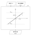
まず、本実施形態に係る制御装置10のハードウェア構成について、図1を参照しながら説明する。図1は、第一の実施形態に係る制御装置10のハードウェア構成の一例を示す図である。
まず、本実施形態に係る制御装置10のハードウェア構成について、図1を参照しながら説明する。図1は、第一の実施形態に係る制御装置10のハードウェア構成の一例を示す図である。
図1に示すように、本実施形態に係る制御装置10は、入力装置11と、表示装置12と、外部I/F13と、通信I/F14と、プロセッサ15と、メモリ装置16とを有する。これらの各ハードウェアは、それぞれがバス17を介して通信可能に接続される。
入力装置11は、例えば、キーボード、マウス、タッチパネル、各種物理ボタン等である。表示装置12は、例えば、ディスプレイ、表示パネル等である。なお、制御装置10は、例えば、入力装置11及び表示装置12のうちの少なくとも一方を有していなくてもよい。
外部I/F13は、記録媒体13a等の外部装置とのインタフェースである。記録媒体13aとしては、例えば、CD(Compact Disc)、DVD(Digital Versatile Disk)、SDメモリカード(Secure Digital memory card)、USB(Universal Serial Bus)メモリカード等が挙げられる。
通信I/F14は、制御装置10を通信ネットワークに接続するためのインタフェースである。プロセッサ15は、例えば、CPU(Central Processing Unit)やMPU(Micro-Processing Unit)等の各種演算装置である。メモリ装置16は、例えば、SSD(Solid State Drive)、RAM(Random Access Memory)、ROM(Read Only Memory)、フラッシュメモリ等の各種記憶装置である。
なお、図1に示すハードウェア構成は一例であって、制御装置10は、他のハードウェア構成であってもよい。例えば、制御装置10は、複数のプロセッサ15や複数のメモリ装置16を有していてもよいし、図示したハードウェア以外の種々のハードウェアを有していてもよい。
<制御装置10の機能構成>
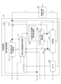
次に、本実施形態に係る制御装置10の機能構成について、図2を参照しながら説明する。図2は、第一の実施形態に係る制御装置10の機能構成の一例を示す図である。
次に、本実施形態に係る制御装置10の機能構成について、図2を参照しながら説明する。図2は、第一の実施形態に係る制御装置10の機能構成の一例を示す図である。
図2に示すように、本実施形態に係る制御装置10は、計測部101と、差分器102と、操作量更新部103と、タイマ104とを有する。これらは、例えば、制御装置10にインストールされた1以上のプログラムが、プロセッサ15等に実行させる処理により実現される。また、本実施形態に係る制御装置10は、忘却付き予測時系列記憶部105を有する。忘却付き予測時系列記憶部105は、例えば、制御装置10が有するメモリ装置16により実現される。
計測部101は、制御周期Tc毎に、制御対象プラント20の制御量yを計測(観測)する。そして、計測部101は、計測した制御量yの最新の値を、制御量現在値y0として出力する。なお、制御対象プラント20の制御量yは、操作量uと外乱vとに応じて決定される。外乱vとしては、例えば、制御量yが温度である場合には外気温の低下又は上昇等が挙げられる。
また、計測部101は、制御周期Tc毎に、操作量更新部103から出力された操作量uを取得(観測)し、取得した操作量uの最新の値を、操作量現在値u0として出力する。
差分器102は、目標値rと、制御量現在値y0との差(偏差)を目標偏差e0として出力する。時刻tにおける目標偏差e0(t)は、e0(t)=r(t)-y0(t)で計算される。なお、本実施形態では、目標値は一定、すなわち、r(t)=定数であるとする。
操作量更新部103は、制御周期Tc毎に、制御対象プラント20に対する操作量uを計算する。ここで、操作量更新部103には、補正目標偏差計算部111と、操作変化量計算部112と、加算器113とが含まれる。
補正目標偏差計算部111は、プラント応答関数{Sθ(t)}と、目標偏差e0(t)と、過去の操作量uの変化量duの時系列データである操作変化量時系列{du(t)}と、先読み長Tpと、忘却係数λとに基づいて、目標偏差e0(t)を補正した補正目標偏差e*(t)を計算する。このとき、補正目標偏差計算部111は、忘却付き予測時系列記憶部105に記憶される予測時系列(未来の或る時刻までの制御量yの予測値の時系列であって、過去の予測値の忘却を考慮した予測値の時系列)を計算及び更新する。ここで、プラント応答関数{Sθ(t)}とはモデルパラメータθを含む関数であり、制御対象プラント20のプラント応答モデルである。プラント応答関数Sθ(・)としては、例えば、時刻tを入力として、制御対象プラント20のステップ応答を出力する関数を用いることができる。なお、補正目標偏差e*(t)の計算方法の詳細については後述する。
操作変化量計算部112は、補正目標偏差e*(t)と制御ゲインkIとに基づいて、操作変化量du(t)を計算する。操作変化量計算部112は、例えば、du(t-3Tc)、du(t-2Tc)、du(t-Tc)という順序で操作変化量du(t)を計算し、出力する。なお、操作変化量duは、制御周期Tc毎に操作量uが変化した量である。
加算器113は、計測部101から出力された操作量現在値u0と、操作変化量計算部112から出力された操作変化量duとを加算して、新たな操作量uを計算する。そして、加算器113は、この新たな操作量uを制御対象プラント20に出力する。新たな操作量uは、u(t)=u0+du(t)=u(t-Tc)+du(t)で計算される。
タイマ104は、制御周期Tc毎に、計測部101と操作量更新部103とを動作させる。すなわち、タイマ104は、制御周期Tc毎に、計測部101と操作量更新部103の動作トリガーとして動作する。制御周期Tcは、制御対象プラント20を制御する周期のことであり、その値は予め設定される。
忘却付き予測時系列記憶部105は、補正目標偏差計算部111によって計算された予測時系列(未来の或る時刻までの制御量yの予測値の時系列であって、過去の予測値の忘却を考慮した予測値の時系列)を記憶する。
以上の機能構成を有することにより、本実施形態に係る制御装置10は、制御周期Tc毎に、計測部101による制御量y及び操作量uの計測と、操作量更新部103による新たな操作量uの計算とを逐次的に繰り返し、制御対象プラント20を制御することができる。
<補正目標偏差計算部111の動作>
次に、補正目標偏差計算部111の動作について、図3を参照しながら説明する。図3は、補正目標偏差計算部111の動作の一例を説明するための図である。
次に、補正目標偏差計算部111の動作について、図3を参照しながら説明する。図3は、補正目標偏差計算部111の動作の一例を説明するための図である。
図3に示すように、補正目標偏差計算部111は、プラント応答関数{Sθ(t)}と、目標偏差e0(t)と、操作変化量時系列{du(t)}と、先読み長Tpとが入力されると、過去の予測値の忘却を考慮して、制御量が過去の操作変化量によって現在時刻tからTp経過後に変化すると予測される値を先読み応答補正値yn(t)として算出する。
そして、補正目標偏差計算部111は、先読み応答補正値yn(t)により目標偏差e0(t)を補正した補正目標偏差e*(t)を出力する。ここで、補正目標偏差e*(t)は、e*(t)=r(t)-(y0(t)+yn(t))=e0(t)-yn(t)で計算される。
ここで、先読み応答補正値yn(t)は、忘却付き予測時系列記憶部105に記憶されている予測時系列を用いて計算される。以下、その計算方法の具体例について説明する。
時刻tで予測した時刻sにおける制御量yの予測値を一般化予測値yn,C(s|t)と定義し、以下により計算する。なお、この一般化予測値yn,C(s|t)は忘却付き予測値と呼ばれてもよい。

このとき、忘却付き予測時系列記憶部105には、現在時刻をtとして、時刻t-Δtから未来の時刻t+Tbまでの一般化予測値yn,C(s|t)が時系列として記憶されているものとする。すなわち、忘却付き予測時系列記憶部105には、yn,C(t-Δt|t),yn,C(t|t),yn,C(t+Δt|t),・・・,yn,C(t+Tb|t)が記憶されているものとする。ここで、Tbは、忘却付き予測時系列記憶部105に記憶される一般化予測値yn,Cの長さ(時系列長)を決める定数であり、Tb=N1Δt(N1は、予め決められた任意の正の整数)と表されるものとする。また、Δtは予測間隔であり、Δt=Tcであるものとする。
一般化予測値yn,Cを用いると、操作変化量時系列{du(t)}のみによる先読み時刻t+Tpにおける制御量yの予測値である先読み応答予測値yn,A(t)は、yn,A(t)=yn,C(t+Tp|t)となる。また、操作変化量時系列{du(t)}のみによる現在時刻tにおける制御量yの予測値である自由応答予測値yn,B(t)は、yn,B(t)=yn,C(t|t)となる。先読み応答予測値yn,A(t)と自由応答予測値yn,B(t)とを用いることで、先読み応答補正値yn(t)は、yn(t)=yn,A(t)-yn,B(t)と計算できる。
ここで、忘却付き予測時系列記憶部105は、新たな操作変化量du(t)が操作変化量計算部112によって計算される毎に、補正目標偏差計算部111によって更新される。このため、忘却付き予測時系列記憶部105を用いることで、一般化予測値yn,Cを毎回再計算するのに比べて、少ない計算量と少ないメモリ量で補正目標偏差e*(t)を計算することができる。以下、忘却付き予測時系列記憶部105の更新方法の具体例について説明する。
時刻tで予測したmΔt先における一般化予測値yn,C(t+mΔt|t)は、以下で表される。
また、時刻t+Δtで予測したmΔt先における一般化予測値yn,C(t+Δt+mΔt|t+Δt)は、以下で表される。
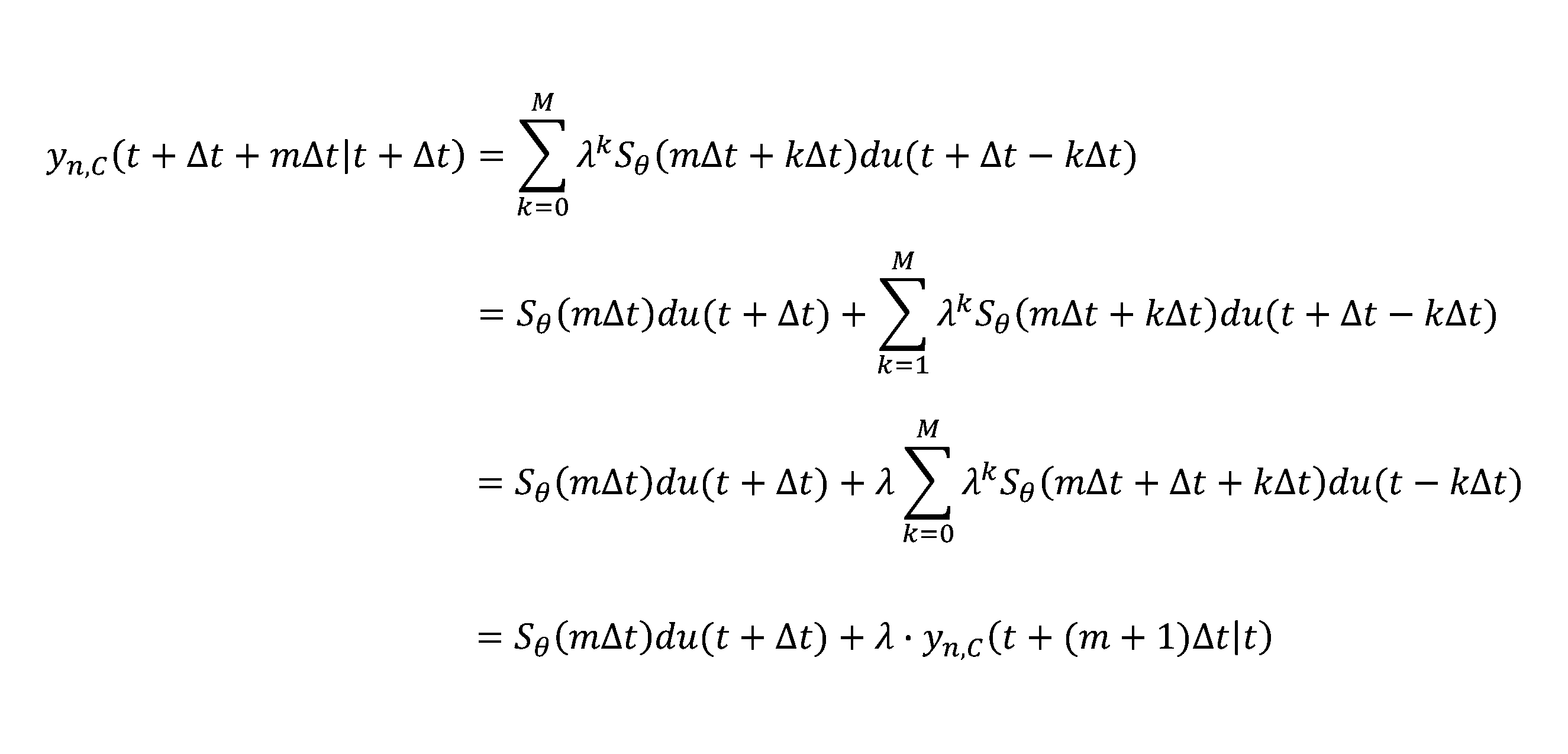
一例として、時刻tで忘却付き予測時系列記憶部105に記憶されている予測時系列と、操作変化量du(t+Δt)とを用いて、時刻t+Δtにおける忘却付き予測時系列記憶部105を更新する場合について、図4を参照しながら説明する。図4は、忘却付き予測時系列記憶部105の更新の一例を説明するための図である。なお、先読み長Tpは、Tp=N2Δt(N2は、N2≦N1を満たす予め決められた任意の正の整数)と表されるものとする。
時刻t+Δtにおける忘却付き予測時系列記憶部105は、yn,C(t|t+Δt),yn,C(t+Δt|t+Δt),yn,C(t+2Δt|t+Δt),・・・,yn,C(t+Δt+Tp|t+Δt),・・・,yn,C(t+Δt+Tb|t+Δt)という予測時系列が記憶される。このとき、yn,C(t|t+Δt)は、yn,C(t|t)に忘却係数λを乗じた値として計算できる。次に、yn,C(t+Δt|t+Δt)は、yn,C(t+Δt|t)に忘却係数λを乗じた値に対して、Sθ(0)du(t+Δt)を加えた値として計算できる。以降、同様に、m=1,2,・・・,N1-1に関して、yn,C(t+Δt+mΔt|t+Δt)は、λ・yn,C(t+(m+1)Δt|t)に対してSθ(mΔt)du(t+Δt)を加えた値として計算できる。なお、yn,C(t+Δt+Tb|t+Δt)は、上記の数1に従って計算される。
このように、忘却付き予測時系列記憶部105では、時刻tにおける予測値を忘却係数λによって忘却しつつ、新しい操作変化量du(t+Δt)の影響を加算することで、時刻t+Δtにおける予測値に更新される。
<操作変化量計算部112の動作>
次に、操作変化量計算部112の動作について、図5を参照しながら説明する。図5は、操作変化量計算部112の動作の一例を説明するための図である。
次に、操作変化量計算部112の動作について、図5を参照しながら説明する。図5は、操作変化量計算部112の動作の一例を説明するための図である。
図5に示すように、操作変化量計算部112は、補正目標偏差e*(t)と制御ゲインkIとが入力されると、補正目標偏差e*(t)に対して制御ゲインkIを乗じて操作変化量du(t)を出力する。すなわち、操作変化量計算部112は、du(t)=kI×e*(t)により操作変化量du(t)を算出する。
ただし、補正目標偏差e*(t)に対して制御ゲインkIを乗じた結果が上限値dumaxを超える場合、操作変化量計算部112は、dumaxを操作変化量du(t)とする。同様に、補正目標偏差e*(t)に対して制御ゲインkIを乗じた結果が下限値duminを下回る場合、操作変化量計算部112は、duminを操作変化量du(t)とする。これにより、上下限範囲に対するリミッターを設けることができる。なお、操作量現在値u0と操作変化量duとが加算器113によって加算された後の操作量uが所定の上下限範囲を逸脱しないように、dumax及びduminを都度設定してもよい。
[第二の実施形態]
以下、第二の実施形態について説明する。なお、第二の実施形態では、第一の実施形態との相違点について説明し、第一の実施形態と同様の構成要素についてはその説明を省略する。
以下、第二の実施形態について説明する。なお、第二の実施形態では、第一の実施形態との相違点について説明し、第一の実施形態と同様の構成要素についてはその説明を省略する。
本実施形態に係る制御装置10は、制御量yを目標値rに追従させるための操作量uの計算とプラント応答モデルのモデルパラメータの推定とをオンライン実行中に繰り返し実行する。これにより、例えば、制御対象プラント20の運用開始後において、プラント特性の季節変動や経年劣化等の継時的変化に追従したモデルパラメータを推定することが可能となる。
<制御装置10の機能構成>
本実施形態に係る制御装置10の機能構成について、図6を参照しながら説明する。図6は、第二の実施形態に係る制御装置10の機能構成の一例を示す図である。
本実施形態に係る制御装置10の機能構成について、図6を参照しながら説明する。図6は、第二の実施形態に係る制御装置10の機能構成の一例を示す図である。
図6に示すように、本実施形態に係る制御装置10は、第一の実施形態で説明した計測部101、差分器102、操作量更新部103、タイマ104及び忘却付き予測時系列記憶部105に加えて、モデルパラメータ推定部106を有する。モデルパラメータ推定部106は、例えば、制御装置10にインストールされた1以上のプログラムが、プロセッサ15等に実行させる処理により実現される。
モデルパラメータ推定部106は、制御周期Tc毎に、制御量現在値y0(t)と操作量現在値u0(t)とを入力し、プラント応答関数{Sθ(t)}のモデルパラメータの推定値θestを計算し、出力する。モデルパラメータ推定部106は、例えば、逐次最小二乗法等といった既知の手法(例えば、特許文献4に記載されている手法等)によりモデルパラメータの推定値θestを計算すればよい。このモデルパラメータの推定値θ=θestは、プラント応答関数{Sθ(t)}に設定される。なお、モデルパラメータの推定値θestを計算する際に、モデルパラメータの初期値θ0が入力されてもよい。
ここで、モデルパラメータθの一例として、プラント応答関数{Sθ(t)}として自己回帰移動平均モデル(ARMA(autoregressive moving average)モデル)を用いた場合について説明する。例えば、制御量yについては過去N点の自己回帰、操作量uについては現在値と過去M点の移動平均を用いたARMAモデルは、以下で表される。
y(k)=a1y(k-1)+a2y(k-2)+・・・+aNy(k-N)+b0u(k)+b1u(k-1)+b2u(k-2)+・・・+bMu(k-M)
なお、N及びMは、予め設定された1以上の整数である。
なお、N及びMは、予め設定された1以上の整数である。
このとき、モデルパラメータθは以下で表される。

なお、上記のARMAモデルは一例であって、例えば、過去L点(Lは予め設定された1以上の整数)の外乱vを考慮したモデルであってもよい。また、ARMAモデルに限られるものではなく、例えば、ARMAXモデル等がプラント応答関数{Sθ(t)}として用いられてもよい。
タイマ104は、制御周期Tc毎に、計測部101と操作量更新部103とモデルパラメータ推定部106とを動作させる。すなわち、タイマ104は、制御周期Tc毎に、更にモデルパラメータ推定部106の動作トリガーとしても動作する。
以上の機能構成を有することにより、本実施形態に係る制御装置10は、制御周期Tc毎に、計測部101による制御量y及び操作量uの計測と、モデルパラメータ推定部106によるモデルパラメータθ=θestの推定と、操作量更新部103による新たな操作量uの計算とを逐次的に繰り返し、制御対象プラント20を制御することができる。
[実施例1]
以下、第二の実施形態に係る制御装置10の実施例1について説明する。本実施例では、制御対象プラント20とプラント応答モデルとの間に誤差がある場合に、第二の実施形態に係る制御装置10の有効性を示す。
以下、第二の実施形態に係る制御装置10の実施例1について説明する。本実施例では、制御対象プラント20とプラント応答モデルとの間に誤差がある場合に、第二の実施形態に係る制御装置10の有効性を示す。
本実施例では、制御対象プラント20のプラント応答モデルが以下のARMAモデルで表されているものとする。
y(k)=θ1y(k-1)+θ2y(k-2)+θ3u(k)+θ4u(k-1)+θ5u(k-2)
状態ベクトルを以下で定義する。
状態ベクトルを以下で定義する。


なお、第一の実施形態に係る制御装置10を用いる場合は、モデルパラメータθが時間変化せずに固定値であるものとすればよい。すなわち、モデルパラメータθ(k)がインデックスkに依存しない、つまりθ(k)=θとすればよい。
本実施例における制御対象プラント20のステップ応答を図7に示す。一方で、本実施例におけるプラント応答モデルのステップ応答を図8に示す。図7及び図8はいずれも時刻0で操作量uが単位ステップ状に変化した際の制御量yの変化を表している。図7及び図8に示すように、制御対象プラント20よりもプラント応答モデルの方が、時定数が長く、プラント応答モデルに誤差(モデル誤差)が生じていると言える。
忘却を行わない場合(つまり、λ=1とした場合)におけるプラント応答モデルの制御応答を図9に示す。図9に示すように、モデル誤差の影響により、制御量yの目標値rへの追従が遅れている。
一方で、忘却を行った場合(本実施例では、λ=0.99とした。)におけるプラント応答モデルの制御応答を図10に示す。図10に示すように、図9と比較すると、制御量yの目標値rへの追従性能が改善している。したがって、第二の実施形態に係る制御装置10(又は、モデルパラメータθが時間変化せずに固定値である場合は第一の実施形態に係る制御装置10でもよい。)では、忘却を考慮した予測時系列の効果により、モデル誤差によって予測が外れることによる制御への悪影響を抑制することができているといえる。
[実施例2]
以下、第二の実施形態に係る制御装置10の実施例2について説明する。本実施例では、未知の外乱が制御対象プラント20に印加されている場合に、第二の実施形態に係る制御装置10の有効性を示す。なお、特に言及した場合を除き、実施例1と同様の設定であるものとする。
以下、第二の実施形態に係る制御装置10の実施例2について説明する。本実施例では、未知の外乱が制御対象プラント20に印加されている場合に、第二の実施形態に係る制御装置10の有効性を示す。なお、特に言及した場合を除き、実施例1と同様の設定であるものとする。
本実施例における制御対象プラント20及びプラント応答モデルのステップ応答を図11に示す。図11は、時刻0で操作量uが単位ステップ状に変化した際の制御量yの変化を表している。本実施例では、制御対象プラント20とプラント応答モデルとが一致しているものとする。
本実施例における目標値r及び外乱vを図12に示す。図12に示すように、本実施例では、時刻500で未知の外乱vがステップ状に印加されるものとする。
忘却を行わない場合(つまり、λ=1とした場合)におけるプラント応答モデルの制御応答を図13に示す。図13に示すように、未知の外乱vの影響により、時刻500以降で制御量yと目標値rとの間にずれが生じており、時刻2000までオフセットが継続している。
一方で、忘却を行った場合(本実施例では、λ=0.99とした。)におけるプラント応答モデルの制御応答を図14に示す。図14に示すように、図13と比較すると、制御量yの目標値rへの追従性能が改善している。したがって、第二の実施形態に係る制御装置10(又は、モデルパラメータθが時間変化せずに固定値である場合は第一の実施形態に係る制御装置10でもよい。)では、忘却を考慮した予測時系列の効果により、未知の外乱によって予測が外れることによる制御への悪影響を抑制することができているといえる。
以上の実施例1及び2により、第二の実施形態に係る制御装置10(又は、モデルパラメータθが時間変化せずに固定値である場合は第一の実施形態に係る制御装置10でもよい。)は、モデル予測制御における未来予測が外れることによる悪影響を抑制し、その結果、制御性能の低下を抑制することができる。
[まとめ]
以上のように、第一の実施形態に係る制御装置10は、過去に行った予測を漸近的に忘却するため、モデル予測制御の予測が外れることによる制御への悪影響を抑制することができる。また、このとき、忘却付き予測時系列記憶部105の更新は高速に実行できるため、応答性を低下させずに、モデル予測制御の予測が外れることによる制御への悪影響を抑制することができる。更に、忘却係数の値は適宜設定することが可能であるため、忘却の強度をユーザ等が調整することも可能である。それに加えて、制御時に目標偏差がオフセットを持つ場合にも有効に対処することができる。
以上のように、第一の実施形態に係る制御装置10は、過去に行った予測を漸近的に忘却するため、モデル予測制御の予測が外れることによる制御への悪影響を抑制することができる。また、このとき、忘却付き予測時系列記憶部105の更新は高速に実行できるため、応答性を低下させずに、モデル予測制御の予測が外れることによる制御への悪影響を抑制することができる。更に、忘却係数の値は適宜設定することが可能であるため、忘却の強度をユーザ等が調整することも可能である。それに加えて、制御時に目標偏差がオフセットを持つ場合にも有効に対処することができる。
第二の実施形態に係る制御装置10は、第一の実施形態で説明した事項に加えて、更にモデルパラメータθを逐次的に推定(学習)する。このため、例えば、モデルパラメータθ自体が経時変化していくような場合に、学習が不十分であった過去の予測を能動的に忘却させることが可能となり、予測が外れやすくなる悪影響を抑制することができる。
本発明は、具体的に開示された上記の実施形態に限定されるものではなく、請求の範囲の記載から逸脱することなく、種々の変形や変更、既知の技術との組み合わせ等が可能である。
本願は、日本国に2022年4月15日に出願された基礎出願2022-067612号に基づくものであり、その全内容はここに参照をもって援用される。
10 制御装置
11 入力装置
12 表示装置
13 外部I/F
13a 記録媒体
14 通信I/F
15 プロセッサ
16 メモリ装置
17 バス
20 制御対象プラント
101 計測部
102 差分器
103 操作量更新部
104 タイマ
105 忘却付き予測時系列記憶部
106 モデルパラメータ推定部
111 補正目標偏差計算部
112 操作変化量計算部
113 加算器
11 入力装置
12 表示装置
13 外部I/F
13a 記録媒体
14 通信I/F
15 プロセッサ
16 メモリ装置
17 バス
20 制御対象プラント
101 計測部
102 差分器
103 操作量更新部
104 タイマ
105 忘却付き予測時系列記憶部
106 モデルパラメータ推定部
111 補正目標偏差計算部
112 操作変化量計算部
113 加算器
Claims (7)
- 制御対象に対する操作量を出力し、前記制御対象の制御量を目標値に追従させる制御装置であって、
前記目標値と、現在の制御量との差である目標偏差を算出するように構成されている目標偏差算出部と、
前記制御対象のプラント応答モデルを表す関数であるプラント応答関数による過去の制御量の予測値を漸近的に忘却させた忘却付き予測時系列を記憶するように構成されている忘却付き予測時系列記憶部と、
前記忘却付き予測時系列に基づいて、所定の先読み長経過後における前記制御量の予測値と前記目標偏差から補正目標偏差を算出するように構成されている補正目標偏差算出部と、
前記補正目標偏差と、所定の制御ゲインとに基づいて、前記操作量の変化量を算出するように構成されている操作変化量算出部と、
前記操作量の変化量を前記操作量に加算して新たな操作量を算出するように構成されている操作量算出部と、
を有する制御装置。 - 前記忘却付き予測時系列に含まれる各予測値は、
現在の前記操作量の変化量と前記プラント応答関数による制御量の予測値との積と、
現在の時刻よりも1つ前の時刻における忘却付き予測時系列に含まれる各予測値のうち、前記プラント応答関数による制御量の予測値の時刻に対応する時刻の予測値を所定の忘却係数により忘却させた値と、の和で表される、請求項1に記載の制御装置。 - 現在の時刻をt、現在よりも1つ前の時刻をt-Δt、前記プラント応答関数をS(・)、前記忘却係数をλ、0以上の整数をmとして、
前記忘却付き予測時系列に含まれる各予測値yn,C(t+mΔt|t)は、
現在の前記操作量の変化量du(t)と前記プラント応答関数による制御量の予測値S(mΔt)との積S(mΔt)du(t)と、λ・yn,C(t+mΔt|t-Δt)との和で表される、請求項2に記載の制御装置。 - 前記忘却係数λは、0≦λ≦1を満たす実数である、請求項3に記載の制御装置。
- 前記制御量と前記操作量とに基づいて、前記プラント応答関数のモデルパラメータを逐次推定するように構成されているモデルパラメータ推定部を更に有する請求項1乃至4の何れか一項に記載の制御装置。
- 制御対象に対する操作量を出力し、前記制御対象の制御量を目標値に追従させる制御装置が、
前記目標値と、現在の制御量との差である目標偏差を算出する目標偏差算出手順と、
前記制御対象のプラント応答モデルを表す関数であるプラント応答関数による過去の制御量の予測値を漸近的に忘却させた忘却付き予測時系列を記憶部に記憶させる忘却付き予測時系列記憶手順と、
前記忘却付き予測時系列に基づいて、所定の先読み長経過後における前記制御量の予測値と前記目標偏差から補正目標偏差を算出する補正目標偏差算出手順と、
前記補正目標偏差と、所定の制御ゲインとに基づいて、前記操作量の変化量を算出する操作変化量算出手順と、
前記操作量の変化量を前記操作量に加算して新たな操作量を算出する操作量算出手順と、
を実行する制御方法。 - 制御対象に対する操作量を出力し、前記制御対象の制御量を目標値に追従させる制御装置に、
前記目標値と、現在の制御量との差である目標偏差を算出する目標偏差算出手順と、
前記制御対象のプラント応答モデルを表す関数であるプラント応答関数による過去の制御量の予測値を漸近的に忘却させた忘却付き予測時系列を記憶部に記憶させる忘却付き予測時系列記憶手順と、
前記忘却付き予測時系列に基づいて、所定の先読み長経過後における前記制御量の予測値と前記目標偏差から補正目標偏差を算出する補正目標偏差算出手順と、
前記補正目標偏差と、所定の制御ゲインとに基づいて、前記操作量の変化量を算出する操作変化量算出手順と、
前記操作量の変化量を前記操作量に加算して新たな操作量を算出する操作量算出手順と、
を実行させるプログラム。
Priority Applications (1)
| Application Number | Priority Date | Filing Date | Title |
|---|---|---|---|
| US18/616,931 US20240272594A1 (en) | 2022-04-15 | 2024-03-26 | Control device, control method, and recording medium |
Applications Claiming Priority (2)
| Application Number | Priority Date | Filing Date | Title |
|---|---|---|---|
| JP2022067612A JP7115656B1 (ja) | 2022-04-15 | 2022-04-15 | 制御装置、制御方法及びプログラム |
| JP2022-067612 | 2022-04-15 |
Related Child Applications (1)
| Application Number | Title | Priority Date | Filing Date |
|---|---|---|---|
| US18/616,931 Continuation US20240272594A1 (en) | 2022-04-15 | 2024-03-26 | Control device, control method, and recording medium |
Publications (1)
| Publication Number | Publication Date |
|---|---|
| WO2023199588A1 true WO2023199588A1 (ja) | 2023-10-19 |
Family
ID=82780731
Family Applications (1)
| Application Number | Title | Priority Date | Filing Date |
|---|---|---|---|
| PCT/JP2023/004834 Ceased WO2023199588A1 (ja) | 2022-04-15 | 2023-02-13 | 制御装置、制御方法及びプログラム |
Country Status (3)
| Country | Link |
|---|---|
| US (1) | US20240272594A1 (ja) |
| JP (1) | JP7115656B1 (ja) |
| WO (1) | WO2023199588A1 (ja) |
Families Citing this family (1)
| Publication number | Priority date | Publication date | Assignee | Title |
|---|---|---|---|---|
| JP7552947B1 (ja) | 2024-04-05 | 2024-09-18 | 富士電機株式会社 | 制御支援装置、制御支援方法、及びプログラム |
Citations (2)
| Publication number | Priority date | Publication date | Assignee | Title |
|---|---|---|---|---|
| JP2019145730A (ja) * | 2018-02-23 | 2019-08-29 | 株式会社Kokusai Electric | 基板処理装置、温度制御方法、半導体装置の製造方法及び温度制御プログラム |
| JP7014330B1 (ja) * | 2021-08-19 | 2022-02-01 | 富士電機株式会社 | 制御装置、制御方法、及びプログラム |
-
2022
- 2022-04-15 JP JP2022067612A patent/JP7115656B1/ja active Active
-
2023
- 2023-02-13 WO PCT/JP2023/004834 patent/WO2023199588A1/ja not_active Ceased
-
2024
- 2024-03-26 US US18/616,931 patent/US20240272594A1/en active Pending
Patent Citations (2)
| Publication number | Priority date | Publication date | Assignee | Title |
|---|---|---|---|---|
| JP2019145730A (ja) * | 2018-02-23 | 2019-08-29 | 株式会社Kokusai Electric | 基板処理装置、温度制御方法、半導体装置の製造方法及び温度制御プログラム |
| JP7014330B1 (ja) * | 2021-08-19 | 2022-02-01 | 富士電機株式会社 | 制御装置、制御方法、及びプログラム |
Also Published As
| Publication number | Publication date |
|---|---|
| JP2023157603A (ja) | 2023-10-26 |
| JP7115656B1 (ja) | 2022-08-09 |
| US20240272594A1 (en) | 2024-08-15 |
Similar Documents
| Publication | Publication Date | Title |
|---|---|---|
| JP6359182B2 (ja) | 機械の動作を制御するための方法およびシステム | |
| JP6513015B2 (ja) | 機械の動作を制御する方法、および機械の動作を反復的に制御する制御システム | |
| JP6927446B1 (ja) | 制御装置、制御方法及びプログラム | |
| JP6380552B2 (ja) | 制御装置、そのプログラム、プラント制御方法 | |
| JP2004503000A (ja) | 多変量マトリクスプロセス制御 | |
| JP2013504133A (ja) | 反復線形部分空間計算による時変、パラメータ変動、及び非線形システムの経験的モデル化のための方法及びシステム | |
| Wang et al. | Markov nonlinear system estimation for engine performance tracking | |
| CN103930912A (zh) | 时序数据分析方法、系统和计算机程序 | |
| JP6901037B1 (ja) | 制御装置、制御方法及びプログラム | |
| JP7014330B1 (ja) | 制御装置、制御方法、及びプログラム | |
| CN115933399A (zh) | 一种高阶无模型自适应迭代学习控制方法 | |
| CN112748660A (zh) | 存储器、加热炉出口温度控制方法、装置和设备 | |
| WO2023199588A1 (ja) | 制御装置、制御方法及びプログラム | |
| JP2021051462A (ja) | 情報処理装置及びプログラム | |
| JP7283095B2 (ja) | 制御装置、制御方法及びプログラム | |
| JP7047966B1 (ja) | プラント応答推定装置、プラント応答推定方法、及びプログラム | |
| CN105955024B (zh) | 船舶增压锅炉主蒸汽压力预测控制方法 | |
| CN116738617A (zh) | 动力系统建模方法、装置、电子设备及存储介质 | |
| CN112748659A (zh) | 存储器、非线性预测控制方法、装置和设备 | |
| JP7115654B1 (ja) | 制御装置、制御方法及びプログラム | |
| JP7275492B2 (ja) | 制御装置、制御方法及びプログラム | |
| JP7409343B2 (ja) | コントローラ、制御方法及び制御プログラム | |
| JP7231102B1 (ja) | プラント応答推定装置、プラント応答推定方法、及びプログラム | |
| CN112748661A (zh) | 存储器、吸收塔液位非线性控制方法、装置和设备 | |
| JP7646534B2 (ja) | プラントの内部状態を可視化する方法、システムおよびプログラム |
Legal Events
| Date | Code | Title | Description |
|---|---|---|---|
| 121 | Ep: the epo has been informed by wipo that ep was designated in this application |
Ref document number: 23788011 Country of ref document: EP Kind code of ref document: A1 |
|
| NENP | Non-entry into the national phase |
Ref country code: DE |
|
| 122 | Ep: pct application non-entry in european phase |
Ref document number: 23788011 Country of ref document: EP Kind code of ref document: A1 |