WO2023199500A1 - 空気調和装置、および制御方法 - Google Patents
空気調和装置、および制御方法 Download PDFInfo
- Publication number
- WO2023199500A1 WO2023199500A1 PCT/JP2022/017888 JP2022017888W WO2023199500A1 WO 2023199500 A1 WO2023199500 A1 WO 2023199500A1 JP 2022017888 W JP2022017888 W JP 2022017888W WO 2023199500 A1 WO2023199500 A1 WO 2023199500A1
- Authority
- WO
- WIPO (PCT)
- Prior art keywords
- air conditioner
- compressor
- time
- refrigerant
- value
- Prior art date
- Legal status (The legal status is an assumption and is not a legal conclusion. Google has not performed a legal analysis and makes no representation as to the accuracy of the status listed.)
- Ceased
Links
Images





Classifications
-
- F—MECHANICAL ENGINEERING; LIGHTING; HEATING; WEAPONS; BLASTING
- F25—REFRIGERATION OR COOLING; COMBINED HEATING AND REFRIGERATION SYSTEMS; HEAT PUMP SYSTEMS; MANUFACTURE OR STORAGE OF ICE; LIQUEFACTION SOLIDIFICATION OF GASES
- F25B—REFRIGERATION MACHINES, PLANTS OR SYSTEMS; COMBINED HEATING AND REFRIGERATION SYSTEMS; HEAT PUMP SYSTEMS
- F25B1/00—Compression machines, plants or systems with non-reversible cycle
Definitions
- the present disclosure relates to an air conditioner and a control method.
- Patent Document 1 JP 2015-21628A discloses an air conditioner. This air conditioner switches the operation of the compressor from continuous operation to intermittent operation when the rotational speed of the compressor motor is lower than a predetermined minimum speed.
- the intermittent operation described above is performed by setting the operating frequency of the compressor to the lowest frequency.
- the amount of power consumption may increase when the operating frequency of the compressor is the lowest frequency.
- the present disclosure has been made to solve such problems, and its purpose is to provide a technique for suppressing power consumption when the operating frequency of the compressor is the lowest frequency.
- the air conditioner of the present disclosure includes a compressor that compresses refrigerant and a control device.
- the control device obtains the on-time from when the compressor is turned on to when the compressor is turned off when the operating frequency of the compressor is the lowest frequency.
- the control device calculates a time constant regarding the capacity of the air conditioner when the operating frequency of the compressor is the lowest frequency. Then, the control device lowers the refrigerant discharge temperature of the refrigerant discharged from the compressor based on the on-time and the time constant.
- the control method of the present disclosure is a control method of an air conditioner including a compressor that compresses refrigerant.
- the control method includes obtaining an on-time from when the compressor is turned on to when the compressor is turned off when the operating frequency of the compressor is the lowest frequency.
- the control method includes calculating a time constant regarding the capacity of the air conditioner when the operating frequency of the compressor is the lowest frequency.
- the control method lowers the refrigerant discharge temperature of refrigerant discharged from the compressor based on an on-time and a time constant.
- FIG. 6 is a diagram for explaining changes in indoor temperature of an air conditioner according to a comparative example.
- FIG. 3 is a diagram for explaining changes in indoor temperature of the air conditioner according to the present embodiment.
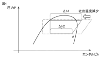
- FIG. 2 is a Ph diagram for explaining a decrease in the capacity of an air conditioner.
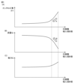
- FIG. 3 is a diagram showing the degree of thirst on the suction side of the compressor.
- FIG. 2 is a diagram for explaining power consumption and the like of an air conditioner according to the present embodiment and an air conditioner according to a comparative example.
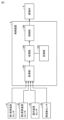
- FIG. 2 is a functional block diagram of a control device and the like.
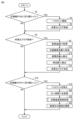
- 7 is a flowchart showing processing of the control device according to the present embodiment. It is an example of a flowchart of target temperature control processing. 7 is an example of a flowchart of target temperature control processing according to the second embodiment. 7 is an example of a flowchart of target temperature control processing according to the second embodiment.
- FIG. 1 is a diagram showing a configuration example of an air conditioner 100.
- the configuration of air conditioner 100 according to Embodiment 1 will be described with reference to FIG. 1.
- the air conditioner 100 is capable of performing cooling operation and heating operation.
- the air conditioner 100 performs a cooling operation or a heating operation based on a user's operation on a setting device (for example, a remote control).
- Solid arrows in FIG. 1 indicate the flow of refrigerant during cooling operation.
- Broken arrows in FIG. 1 indicate the flow of refrigerant during heating operation.
- the air conditioner 100 includes an outdoor unit 101 and an indoor unit 102.
- the outdoor unit 101 and the indoor unit 102 are connected by a gas pipe 21 and a liquid pipe 22.
- a portion of the pipe 20 constitutes a gas pipe 21 and a liquid pipe 22.
- the outdoor unit 101 includes a compressor 1 , a four-way valve 2 , an outdoor heat exchanger 3 , an expansion valve 4 , an outdoor blower 6 , and a control device 8 .
- Indoor unit 102 includes an indoor heat exchanger 5 and an indoor blower 7.
- the refrigerant circuit 10 includes a compressor 1, a four-way valve 2, an outdoor heat exchanger 3, an expansion valve 4, and an indoor heat exchanger 5.
- the compressor 1, four-way valve 2, outdoor heat exchanger 3, expansion valve 4, and indoor heat exchanger 5 are connected by piping 20.
- the refrigerant circuit 10 is configured to circulate refrigerant.
- the refrigerant is used in a refrigeration cycle that transports heat between the outdoor unit 101 and the indoor unit 102.
- the refrigerant is a non-azeotropic refrigerant mixture.
- the non-azeotropic refrigerant mixture contains R32 and may also contain R1234yf as another refrigerant.
- the non-azeotropic mixed refrigerant may contain R1123 or R1234ze as another refrigerant. Further, the non-azeotropic mixed refrigerant may be a mixed refrigerant of three or more types.
- the refrigerant circuit 10 is configured such that during cooling operation, refrigerant circulates in the order of the compressor 1, the four-way valve 2, the outdoor heat exchanger 3, the expansion valve 4, the indoor heat exchanger 5, and the four-way valve 2.
- the refrigerant circuit 10 is configured such that during heating operation, the refrigerant circulates in the order of the compressor 1, the four-way valve 2, the indoor heat exchanger 5, the expansion valve 4, the outdoor heat exchanger 3, and the four-way valve 2. .
- the compressor 1 is configured to compress refrigerant.
- the compressor 1 is for compressing a non-azeotropic mixed refrigerant flowing into a heat exchanger (outdoor heat exchanger 3 or indoor heat exchanger 5).
- the compressor 1 is configured to compress the sucked refrigerant and discharge it.
- the compressor 1 may be configured to have a variable capacity.
- the four-way valve 2 is configured to switch the flow of the refrigerant so that the refrigerant compressed by the compressor 1 flows to the outdoor heat exchanger 3 or the indoor heat exchanger 5.
- the four-way valve 2 has a first port P1 to a fourth port P4.
- the first port P1 is connected to the discharge side of the compressor 1.
- the second port P2 is connected to the suction side of the compressor 1.
- the third port P3 is connected to the outdoor heat exchanger 3.
- the fourth port P4 is connected to the indoor heat exchanger 5.
- the four-way valve 2 is configured to allow the refrigerant discharged from the compressor 1 to flow into the outdoor heat exchanger 3 during cooling operation.
- the first port P1 of the four-way valve 2 is connected to the third port P3, and the second port P2 is connected to the fourth port P4. Furthermore, the four-way valve 2 is configured to allow the refrigerant discharged from the compressor 1 to flow into the indoor heat exchanger 5 during heating operation. During heating operation, in the four-way valve 2, the first port P1 is connected to the fourth port P4, and the second port P2 is connected to the third port P3.
- the outdoor heat exchanger 3 is configured to perform heat exchange between the refrigerant flowing inside the outdoor heat exchanger 3 and the air flowing outside the outdoor heat exchanger 3.
- the outdoor heat exchanger 3 is configured to function as a condenser that condenses refrigerant during cooling operation, and to function as an evaporator that evaporates refrigerant during heating operation.
- the indoor heat exchanger 5 is configured to perform heat exchange between the refrigerant flowing inside the indoor heat exchanger 5 and the air flowing outside the indoor heat exchanger 5.
- the indoor heat exchanger 5 is configured to function as an evaporator to evaporate refrigerant during cooling operation, and to function as a condenser to condense refrigerant during heating operation.
- the condenser formed by the outdoor heat exchanger 3 and the condenser formed by the indoor heat exchanger 5 may be collectively referred to as a "condenser.”
- the evaporator formed by the outdoor heat exchanger 3 and the evaporator formed by the indoor heat exchanger 5 may be collectively referred to as an "evaporator.”
- the expansion valve 4 is configured to reduce the pressure by expanding the refrigerant condensed in the condenser.
- the expansion valve 4 is configured to reduce the pressure of the refrigerant condensed by the outdoor heat exchanger 3 during cooling operation, and to reduce the pressure of the refrigerant condensed by the indoor heat exchanger 5 during heating operation.
- the expansion valve 4 is, for example, an electromagnetic expansion valve.
- the outdoor blower 6 is configured to blow outdoor air to the outdoor heat exchanger 3. That is, the outdoor blower 6 is configured to supply air to the outdoor heat exchanger 3.
- the indoor blower 7 is configured to blow indoor air to the indoor heat exchanger 5. That is, the indoor blower 7 is configured to supply air to the indoor heat exchanger 5.
- the control device 8 is configured to control each device of the air conditioner 100.
- the control device 8 is electrically connected to the compressor 1, the four-way valve 2, the expansion valve 4, the outdoor blower 6, the indoor blower 7, etc., and is configured to control their operations.
- control device 8 controls the compressor 1 and the like based on the set temperature and the indoor temperature.
- the set temperature is set by the user, for example.
- the indoor temperature is the temperature of the space (indoor) in which the air conditioner 100 is installed.
- the control device 8 controls the compressor 1 and the like so that the indoor temperature approaches the set temperature, for example.
- the control device 8 controls the operating frequency of the motor of the compressor 1 (or the rotational speed of the motor) according to the heat load (air conditioning load).
- the control device 8 controls the operating frequency according to the heat load required to bring the indoor temperature to the set temperature (to cool or heat the indoor temperature).
- the control device 8 lowers the operating frequency as the heat load becomes smaller.
- the lowest frequency which is the lowest value of the operating frequency, is defined as the operating frequency.
- the control device 8 lowers the operating frequency, and when the operating frequency reaches the lowest frequency and the heat load is small, the compressor 1 is operated intermittently.
- the intermittent operation is an operation in which an on state in which the compressor 1 is driven and an off state in which the compressor 1 is stopped are repeated.
- control device 8 includes a CPU (Central Processing Unit) 81 and a memory 82 as main components.
- the CPU 81 executes various processes and calculations. Each component is interconnected by a data bus.
- the memory 82 includes ROM (Read Only Memory), RAM (Random Access Memory), and the like.
- the CPU 81 is also called a processor.
- the ROM stores programs executed by the CPU 81.
- the RAM temporarily stores data generated by executing programs in the CPU 81.
- RAM can function as temporary data memory that is used as a work area.
- the air conditioner 100 further includes a first evaporation temperature sensor 41, a second evaporation temperature sensor 42, an indoor temperature sensor 43, and a frequency sensor 44.
- the first evaporation temperature sensor 41 is installed near the indoor heat exchanger 5.
- the first evaporation temperature sensor 41 detects the evaporation temperature of refrigerant by the indoor heat exchanger 5 (evaporator) during cooling operation.
- the second evaporation temperature sensor 42 is installed near the outdoor heat exchanger 3.
- the second evaporation temperature sensor 42 detects the evaporation temperature of the refrigerant by the outdoor heat exchanger 3 (evaporator) during heating operation.
- the indoor temperature sensor 43 is installed in the room where the indoor unit 102 is installed.
- the indoor temperature sensor 43 detects the indoor temperature.
- Frequency sensor 44 is installed in compressor 1.
- the frequency sensor 44 detects the frequency of the compressor motor (the operating frequency of the compressor 1).
- the first evaporation temperature sensor 41 and the second evaporation temperature sensor 42 correspond to the "first sensor” of the present disclosure.
- the frequency sensor 44 corresponds to the "second sensor” of the present disclosure.
- the detection values detected by the first evaporation temperature sensor 41 , the second evaporation temperature sensor 42 , the indoor temperature sensor 43 , and the frequency sensor 44 are input to the control device 8 .
- FIG. 2 is a diagram for explaining changes in indoor temperature of an air conditioner according to a comparative example.
- FIG. 3 is a diagram for explaining changes in the indoor temperature of the air conditioner 100 of the present embodiment. Note that FIGS. 2 and 3 illustrate a case where the air conditioner 100 is in a cooling operation and is performing an intermittent operation.
- FIG. 2(A) is a diagram showing changes in indoor temperature.
- the indoor temperature is detected by an indoor temperature sensor.
- FIG. 2(B) is a diagram showing the capacity of the air conditioner. The capacity is also referred to as cooling capacity or heating capacity, for example.
- FIG. 2(C) is a diagram showing the frequency of the compressor. In FIG. 2 and FIG. 3, which will be described later, the horizontal axis indicates time.
- the vertical axis in FIGS. 2(A) and 3(A) indicates the indoor temperature.
- the vertical axis in FIGS. 2(B) and 3(B) indicates the capacity (for example, cooling capacity) of the air conditioner.
- the vertical axis in FIGS. 2(B) and 3(B) indicates the capacity Q of the air conditioner.
- the vertical axis in FIGS. 2(C) and 3(C) indicates the frequency of the compressor 1.
- the air conditioner when the set temperature T is set by the user, the air conditioner sets an upper limit value Tmax and a lower limit value Tmin. For example, the air conditioner calculates the upper limit value Tmax by adding a predetermined difference value S to the set temperature T, and calculates the upper limit value Tmin by subtracting the difference value S from the set temperature T.
- the air conditioner lowers the indoor temperature by driving the compressor (that is, turning the compressor on).
- the capacity of the air conditioner gradually increases from timing ts1 in a temporary delay type behavior.
- the operating frequency of the compressor changes from 0 to the lowest frequency Fmin.
- the air conditioner stops the compressor (that is, turns the compressor off). This causes the indoor temperature to rise.
- the capacity of the air conditioner becomes 0 at timing ts2.
- the operating frequency of the compressor becomes 0 from the lowest frequency Fmin.
- the indoor temperature reaches the target value (set temperature T) after the refrigeration cycle (compressor 1) starts but before the refrigeration cycle stabilizes.
- the compressor is turned off at timing ts2 while the cooling capacity is increasing. In other words, the compressor stops before the refrigeration cycle becomes stable.
- the compressor is stopped when the cooling capacity reaches Q1. Therefore, the coefficient of performance (COP) of the air conditioner may deteriorate, and as a result, power consumption during intermittent operation may increase.
- COP coefficient of performance
- the air conditioner 100 of this embodiment intentionally reduces the capacity of the air conditioner 100, as shown in FIG. 3(B).
- the air conditioner 100 shortens the time constant when the capacity of the air conditioner 100 is reduced, and the time constant when the capacity of the air conditioner 100 is not reduced (FIG. 3(A)). be able to.
- the time constant is a time constant in a temporary delay system (temporary delay element) of the performance of the air conditioner 100.
- the air conditioner 100 can secure a stable time Tm (see FIG. 3(B)) during which the refrigeration cycle can operate in a stable state. As a result, the air conditioner 100 can reduce power consumption during intermittent operation. Further, in FIG. 3, an on-time T1, which will be described later, is shown.
- air conditioner 100 lowers the target temperature in order to reduce the capacity of air conditioner 100.
- the target temperature is a target value of the temperature of the refrigerant discharged from the compressor 1 (hereinafter also referred to as "refrigerant discharge temperature").
- the target temperature is stored in the RAM of the memory 82, for example.
- the air conditioner 100 increases the opening degree of the expansion valve 4 so that the refrigerant discharge temperature approaches the lowered target temperature.
- control device 8 controls the opening degree of the expansion valve 4 so that the suction temperature or degree of superheat of the saturated gas refrigerant into the compressor 1 is about 0 to 5 degrees.
- the opening degree of the expansion valve 4 is small, the degree of superheat increases.
- the degree of superheating increases, the suction temperature of the compressor 1 increases, and the refrigerant discharge temperature from the compressor 1 increases.
- the opening degree of the expansion valve 4 when the opening degree of the expansion valve 4 is large, the degree of superheating decreases and the gas-liquid two-phase refrigerant flows into the inlet of the compressor 1.
- the refrigerant discharge temperature from the compressor 1 becomes low. Therefore, even when the opening degree of the expansion valve 4 is controlled so that the refrigerant discharge temperature of the compressor 1 becomes a predetermined temperature, the state of refrigerant suction into the compressor 1 can be controlled.
- the opening degree of the expansion valve 4 when the opening degree of the expansion valve 4 is large, the air conditioner 100 can lower the refrigerant discharge temperature by the compressor 1.
- FIG. 4 is a Ph diagram for explaining the decrease in the capacity of the air conditioner 100.
- the air conditioner 100 operates the compressor 1 intermittently and the target temperature is lowered and the opening degree of the expansion valve 4 is increased, the following state occurs.
- the opening degree of the expansion valve 4 is increased, gas-liquid two-phase refrigerant flows into the inlet of the compressor 1 as described above. Therefore, the refrigerant density on the suction side A of the compressor 1 increases. As a result, the refrigerant circulation flow rate Gr increases.
- the superheated gas refrigerant becomes a gas-liquid two-phase refrigerant. Therefore, the amount of refrigerant present in the evaporator increases. Therefore, the amount of liquid refrigerant on the condenser side decreases, and the degree of subcooling decreases. As a result, the enthalpy difference ⁇ h1 and the enthalpy difference ⁇ h2 decrease.
- the enthalpy difference ⁇ h1 is the difference value between the enthalpy at the inlet of the condenser and the enthalpy at the outlet of the condenser.
- the enthalpy difference ⁇ h2 is the difference value between the enthalpy at the inlet of the evaporator and the enthalpy at the outlet of the evaporator.
- the enthalpy difference ⁇ h1 and the enthalpy difference ⁇ h2 are also collectively referred to as "enthalpy difference ⁇ h.”
- the air conditioner 100 is able to reduce the refrigerant discharge temperature by increasing the opening degree of the expansion valve 4 (the refrigerant discharge temperature can be brought closer to the "reduced target temperature"), and as a result, As a result, the capacity of the air conditioner 100 can be reduced.
- FIG. 5 is a diagram showing the degree of thirst on the suction side of the compressor 1.
- the horizontal axis indicates the degree of thirst on the suction side of the compressor 1.
- the vertical axis in FIG. 5(A) shows the enthalpy difference ⁇ h
- the vertical axis in FIG. 5(B) shows the refrigerant circulation flow rate Gr
- the vertical axis in FIG. 5(C) shows the capacity of the air conditioner 100.
- FIG. 6 is a diagram for explaining power consumption and the like of the air conditioner 100 of the present embodiment and the air conditioner of the comparative example.
- the air conditioner 100 of this embodiment is shown by a solid line
- the air conditioner of the comparative example is shown by a broken line.
- FIG. 6(A) the capacity of the air conditioner 100 and the capacity of the air conditioner of the comparative example are shown.
- FIG. 6(B) the power consumption of the air conditioner 100 and the power consumption of the air conditioner of the comparative example are shown.
- the air conditioner 100 reduces the capacity of the air conditioner 100 by lowering the refrigerant discharge temperature by the compressor 1 (lowering the target temperature) during intermittent operation. let For this reason, the time it takes for the indoor temperature to reach the set temperature becomes longer than before the performance was lowered. Therefore, it is possible to secure a stable time Tm (see also FIG. 3) during which the refrigeration cycle of the air conditioner 100 operates in a stable state.
- the COP is higher during the period when the refrigeration cycle is stable than during the period from when the compressor 1 is started until the refrigeration cycle is stabilized. Therefore, the air conditioner 100 has the effect of suppressing energy consumption by lowering the refrigerant discharge temperature during intermittent operation.
- the capacity of the air conditioner 100 decreases, but the circulating flow rate Gr of the refrigerant increases (see FIG. 5).
- the time it takes for the refrigeration cycle to stabilize becomes shorter. This shortens the period of inefficient operation (the period from when the compressor 1 is started until the refrigeration cycle becomes stable), thereby increasing the efficiency of intermittent operation.
- the above-mentioned effects are especially achieved when intermittent operation is performed without time for the refrigeration cycle to stabilize.
- the air conditioner 100 uses predetermined parameters to determine whether or not the operation is inefficient. Thereby, the air conditioner 100 can perform efficient intermittent operation by securing the stabilization time Tm, increasing the circulation flow rate, and quickly stabilizing the refrigeration cycle.
- FIG. 7 is a functional block diagram of the control device 8 and the like.
- the control device 8 includes an acquisition section 103, a processing section 104, a control section 106, and a storage section 108.
- the first evaporation temperature sensor 41 detects the evaporation temperature of the refrigerant by the indoor heat exchanger 5 during cooling operation.
- the evaporation temperature is output to the control device 8.
- the acquisition unit 103 acquires the evaporation temperature.
- the second evaporation temperature sensor 42 detects the evaporation temperature of the refrigerant by the outdoor heat exchanger 3 during heating operation.
- the evaporation temperature is output to the control device 8.
- the acquisition unit 103 acquires the evaporation temperature.
- the indoor temperature sensor 43 detects the indoor temperature where the air conditioner 100 is installed.
- the indoor temperature is output to the control device 8.
- the acquisition unit 103 acquires the indoor temperature.
- the frequency sensor 44 detects the operating frequency of the compressor 1.
- the operating frequency is output to the control device 8.
- the acquisition unit 103 acquires the operating frequency.
- the evaporation temperature, indoor temperature, and operating frequency acquired by the acquisition unit 103 are output to the processing unit 104. Note that the processing unit 104 uses the evaporation temperature from the first evaporation temperature sensor 41 during cooling operation, and uses the evaporation temperature from the second evaporation temperature sensor 42 during heating operation.
- the processing unit 104 obtains the on-time when the operating frequency is the lowest frequency.
- the on time is the time when the compressor 1 is in the on state. For example, during cooling operation, the processing unit 104 starts measuring the on-time (at timing ts1) when the indoor temperature reaches Tmax (see FIG. 3). Then, when the indoor temperature reaches Tmin (see FIG. 3) (at timing ts2), the processing unit 104 ends the measurement of the on-time and acquires the on-time.
- the on time is the time from timing ts1 (see FIG. 3) to timing ts2 when the on state changes from the on state controlled at the timing ts1 to the off state.
- the processing unit 104 calculates the circulating flow rate Gr of the refrigerant based on the following equation (1).
- Gr Vst ⁇ v ⁇ s ⁇ Fz (1)
- Vst on the right side of equation (1) is the stroke volume of the compressor 1, and is a predetermined fixed value.
- ⁇ v on the right side of equation (1) is the volumetric efficiency of the compressor 1.
- ⁇ v is a fixed value.
- ⁇ v may be calculated using a predetermined calculation formula.
- ⁇ s on the right side of equation (1) is the saturated gas density. The saturated gas density is calculated based on the evaporation temperature acquired by the acquisition unit 103.
- a predetermined calculation formula or a predetermined table is used.
- Fz on the right side of equation (1) is the operating frequency of the compressor 1 and is obtained from the frequency sensor 44.
- the processing unit 104 calculates a time constant Tc using the following equation (2) using the circulating flow rate Gr and the amount of refrigerant sealed in the refrigeration cycle (hereinafter also referred to as "refrigerant amount M"). do.
- Tc M/Gr (2) That is, the processing unit 104 calculates the time constant Tc using the following equation (3), which summarizes equations (1) and (2).
- P in equation (3) is "M/Vst ⁇ v” and is a fixed value. That is, the processing unit 104 can calculate the time constant tc based on the evaporation temperature (saturated gas density), the operating frequency of the compressor 1, and the fixed value P.
- the processing unit 104 acquires the on-time. Furthermore, the processing unit 104 compares the first multiplication value and the on time T1.
- the first multiplication value is a value obtained by multiplying the time constant Tc calculated by equation (2) by the first coefficient A.
- the case where the on-time is less than the first multiplication value is the case where the compressor 1 is stopped before the refrigeration cycle is stabilized (that is, the state is as shown in FIG. 2(B)). Therefore, in such a case, the control device 8 lowers the target temperature.
- the lowered target temperature is stored in the storage unit 108, and the opening degree of the expansion valve 4 corresponding to the lowered target temperature is calculated.
- the opening degree is calculated using a predetermined calculation formula, a predetermined table, or the like. Then, the processing section 104 outputs the opening degree to the control section 106.
- the control unit 106 controls the opening degree of the expansion valve 4 to match the opening degree acquired from the processing unit 104. Thereby, the control device 8 can lower the refrigerant discharge temperature (the capacity of the air conditioner 100 can be lowered). As a result, the performance of the air conditioner 100 behaves as shown in FIG. 3(B).
- the processing unit 104 returns the target temperature to the initial value (hereinafter also referred to as "initial target temperature").
- the processing section 104 outputs the opening degree (initial opening degree) of the expansion valve 4 corresponding to the initial target temperature to the control section 106 .
- the initial opening degree is a predetermined value.
- the control unit 106 controls the opening degree of the expansion valve 4 so as to reach the initial opening degree acquired from the processing unit 104. Thereby, the control device 8 can return the reduced refrigerant discharge temperature to the initial value (return the capacity of the air conditioner 100).
- FIG. 8 is a flowchart showing the processing of the control device 8 of this embodiment.
- This flowchart is a flowchart executed during refrigeration operation.
- This flowchart is a process that is executed every predetermined period (for example, 0.1 seconds) when the frequency of the compressor 1 is the lowest frequency.
- step S2 the control device 8 determines whether the compressor 1 has been switched from the off state to the on state. This determination is realized by determining whether the indoor temperature has reached Tmax.
- the compressor 1 is switched to the on state (when the indoor temperature reaches Tmax, that is, YES in step S2), the process proceeds to step S4.
- the determination in step S2 is NO, the process proceeds to step S6.
- step S4 the control device 8 starts measuring the on-time T1.
- step S5 the control device 8 stores an uncalculated flag in a predetermined storage area (for example, RAM).
- the uncalculated flag is a flag indicating that the time constant Tc at the on time T1 has not been calculated.
- step S6 the control device 8 determines whether an uncalculated flag is stored. If the uncalculated flag is stored (YES in step S6), that is, if the time constant Tc has not been calculated, the process proceeds to step S8. Further, if the uncalculated flag is not stored (NO in step S6), the process proceeds to step S16.
- step S8 the control device 8 acquires the evaporation temperature ET.
- the evaporation temperature ET is a value obtained from the first evaporation temperature sensor 41 or the second evaporation temperature sensor 42.
- step S10 the control device 8 acquires the frequency Fz of the compressor 1.
- step S12 the control device 8 calculates the circulating flow rate Gr of the refrigerant based on equation (1).
- step S14 the control device 8 calculates the time constant Tc based on equation (2).
- step S15 the control device 8 erases the uncalculated flag since the time constant Tc has been calculated.
- step S16 the control device 8 determines whether the compressor 1 has been switched from the on state to the off state. This determination is realized by determining whether the indoor temperature has reached Tmin.
- the control device 8 stops counting the on-time T1 started in step S4.
- step S20 the control device 8 obtains the on-time T1.
- step S22 the control device 8 executes target temperature control processing, which will be described later.
- step S24 the control device 8 adjusts the opening degree of the expansion valve 4 so that the refrigerant discharge temperature reaches the target temperature controlled by the target temperature control process.
- FIG. 9 is an example of a flowchart of the target temperature control process in step S22.
- the control device 8 determines whether the on-time T1 is less than the first multiplier value.
- the first multiplication value is the value obtained by multiplying the time constant Tc calculated in step S14 by the first coefficient A.
- step S25 If the on-time is less than the first multiplication value (YES in step S25), the control device 8 lowers the target temperature by a predetermined amount in step S28. For example, the target temperature is lowered by subtracting a predetermined value from the current target temperature. Further, if the on-time is equal to or greater than the first multiplication value (NO in step S25), the control device 8 returns the target temperature to the initial value in step S26. The process then proceeds to step S24.
- the air conditioner 100 controls the refrigerant discharge temperature based on the on-time T1 and the time constant Tc when the operating frequency of the compressor 1 is the lowest frequency (in the case of intermittent operation). decrease. Therefore, the air conditioner 100 can suppress power consumption when the operating frequency of the compressor 1 is the lowest frequency (in the case of intermittent operation).
- the air conditioner 100 lowers the refrigerant discharge temperature based on the comparison between the on-time T1 and the time constant Tc.
- the air conditioner 100 lowers the refrigerant discharge temperature when the on-time T1 is less than the first multiplied value obtained by multiplying the time constant Tc by the first coefficient A. Therefore, the air conditioner 100 can lower the refrigerant discharge temperature through a relatively simple determination process.
- the first coefficient A has a value of 2 or more and 4 or less. Therefore, it is possible to improve accuracy in determining whether or not to lower the refrigerant discharge temperature.
- the air conditioner 100 can suppress the continuation of a state in which the performance of the air conditioner 100 is reduced.
- the control device 8 calculates the time constant Tc based on the evaporation temperature ET and the operating frequency Fz of the compressor 1. Therefore, the control device 8 can calculate the time constant Tc with a relatively simple calculation. Further, the control device 8 decreases the refrigerant discharge temperature by increasing the opening degree of the expansion valve 4. Therefore, the control device 8 can lower the refrigerant discharge temperature with a relatively simple process.
- the processing mainly occurs when the air conditioner 100 is performing the cooling operation.
- the same effects as described above can be achieved by performing the same processing as the above-mentioned processing.
- the process for lowering the refrigerant discharge temperature (the process for lowering the capacity of the air conditioner 100) is a process for increasing the opening degree of the expansion valve 4.
- the process for reducing the refrigerant discharge temperature (the process for reducing the capacity of the air conditioner 100) may be performed using other methods.
- the on-time at the left end of FIG. 3(B) the on-time in a state where the capacity of the air conditioner 100 is not reduced is shown.
- the on time at the left end indicates the first on time when intermittent operation is started.
- the capacity of the air conditioner 100 is reduced based on the previous on time. Therefore, during the first ON time after the intermittent operation is started, the performance of the air conditioner 100 is not reduced.
- FIG. 10 is a diagram showing an example of the target temperature control process (step S22) of the second embodiment.
- the control device 8 determines whether the on-time T1 is less than the first multiplier value. If the on-time T1 is greater than or equal to the first multiplication value (NO in step S52), the process proceeds to step S26. On the other hand, if the on-time T1 is less than the first multiplication value (YES in step S52), the process proceeds to step S54.
- step S54 the control device 8 determines whether the on-time T1 is less than the second multiplier value.
- the second multiplication value is a value obtained by multiplying the time constant by the second coefficient B. Further, as shown by the * mark in FIG. 10, the second coefficient B is smaller than the first coefficient A. If the on-time T1 is equal to or greater than the second multiplication value (NO in step S54), the target temperature is lowered by subtracting the value P1 from the target temperature in step S58. On the other hand, if the on-time T1 is less than the second multiplication value (YES in step S54), the process proceeds to step S56.
- P1 corresponds to the "first value" of the present disclosure.
- step S56 the control device 8 determines whether the on-time T1 is less than the third multiplication value.
- the third multiplication value is a value obtained by multiplying the time constant by the third coefficient C. Further, as shown by the * mark in FIG. 10, the third coefficient C is smaller than the second coefficient B. If the on-time T1 is equal to or greater than the third multiplication value (NO in step S56), the target temperature is lowered by subtracting the value P2 from the target temperature in step S60. On the other hand, if the on-time T1 is less than the third multiplication value (YES in step S56), the process proceeds to step S62. In step S62, the target temperature is lowered by subtracting the value P3 from the target temperature.
- P3 is larger than P2, and P2 is larger than P1.
- P2 and P3 correspond to the "second value" of the present disclosure.
- the refrigerant discharge temperature can be controlled more precisely based on the time constant Tc and the on-time T1.
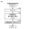
- FIG. 11 is a diagram showing an example of the target temperature control process (step S22) of the third embodiment.
- the control device 8 calculates a ratio value X between the on-time T1 and the time constant Tc.
- the ratio value X in the example of step S72 is a value obtained by dividing the time constant Tc by the on-time T1.
- step S74 the control device 8 substitutes the ratio value X into a predetermined function f(X). Through this substitution, the control device 8 obtains the calculated value ⁇ .
- the control device 8 changes the target temperature by subtracting ⁇ from the target temperature.
- the function f(X) corresponds to the "predetermined calculation formula" of the present disclosure.
- the calculated value ⁇ includes a value that increases the decreased refrigerant discharge temperature.
- the value may include, for example, a value that returns the reduced refrigerant discharge temperature to the temperature before the reduction.
- the calculated value ⁇ is a negative value, a zero value, or a positive value. If the ratio value X is small, such as after the target temperature has been lowered, a negative value is derived from the function f(X) as the calculated value ⁇ . In this case, since the calculated value ⁇ , which is a negative value, is subtracted from the target temperature, the target temperature increases. Thereby, the control device 8 can return the decreased refrigerant discharge temperature to the temperature before the decrease.
- the ratio value X may be a value obtained by dividing the on-time T1 by the time constant Tc. In this case, the calculated value ⁇ of the function f(X) becomes smaller as the ratio value X becomes larger.
- the refrigerant discharge temperature can be controlled more precisely based on the time constant Tc, the on-time T1, and the predetermined function f(X).
- the calculated value ⁇ of the function f(X) includes a value that increases the decreased refrigerant discharge temperature. Therefore, the air conditioner 100 can suppress the continuation of a state in which the performance of the air conditioner 100 is reduced.
- Embodiment 4 In the first to third embodiments described above, a configuration has been described in which the control device 8 lowers the target temperature by subtracting some value from the target temperature. However, the target temperature may be lowered by other methods. For example, the control device 8 may reduce the target temperature by multiplying the target temperature by a correction coefficient.
- 1 Compressor 2 Four-way valve, 3 Outdoor heat exchanger, 4 Expansion valve, 5 Indoor heat exchanger, 6 Outdoor blower, 7 Indoor blower, 8 Control device, 10 Refrigerant circuit, 20 Piping, 21 Gas pipe, 22 Liquid pipe , 41 First evaporation temperature sensor, 42 Second evaporation temperature sensor, 43 Indoor temperature sensor, 44 Frequency sensor, 81 CPU, 82 Memory, 100 Air conditioner, 101 Outdoor unit, 102 Indoor unit, 103 Acquisition unit, 104 Processing unit , 106 control unit, 108 storage unit.
Landscapes
- Engineering & Computer Science (AREA)
- Physics & Mathematics (AREA)
- Mechanical Engineering (AREA)
- Thermal Sciences (AREA)
- General Engineering & Computer Science (AREA)
- Air Conditioning Control Device (AREA)
Abstract
空気調和装置(100)は、冷媒を圧縮する圧縮機(1)と、制御装置(8)とを備える。制御装置(8)は、圧縮機(1)の運転周波数が最低周波数である場合に圧縮機(1)がオン状態になったときからオフ状態になるときまでのオン時間を取得する。制御装置(8)は、圧縮機の運転周波数が最低周波数である場合に、空気調和装置の能力に関する時定数を算出する。そして、制御装置(8)は、圧縮機(1)から吐出される冷媒の冷媒吐出温度を、オン時間と時定数とに基づいて低下させる。
Description
本開示は、空気調和装置、および制御方法に関する。
特開2015-21628号公報(特許文献1)には、空気調和装置が開示されている。この空気調和装置は、圧縮機のモータの回転速度が所定の最低速度が下回る場合に、圧縮機の運転を連続運転から断続運転に切り替える。
上述の空気調和装置において、換言すると、圧縮機の運転周波数を最低周波数とすることにより、上述の断続運転を実行する。しかしながら、上述の空気調和装置においては、圧縮機の運転周波数が最低周波数である場合に消費電力量が増大する場合がある。
本開示は、このような課題を解決するためになされたものであって、その目的は、圧縮機の運転周波数が最低周波数である場合の消費電力量を抑制する技術を提供することである。
本開示の空気調和装置は、冷媒を圧縮する圧縮機と、制御装置とを備える。制御装置は、圧縮機の運転周波数が最低周波数である場合に圧縮機がオン状態になったときからオフ状態になるときまでのオン時間を取得する。制御装置は、圧縮機の運転周波数が最低周波数である場合に、空気調和装置の能力に関する時定数を算出する。そして、制御装置は、圧縮機から吐出される冷媒の冷媒吐出温度を、オン時間と時定数とに基づいて低下させる。
本開示の制御方法は、冷媒を圧縮する圧縮機を備える空気調和装置の制御方法である。制御方法は、圧縮機の運転周波数が最低周波数である場合に圧縮機がオン状態になったときからオフ状態になるときまでのオン時間を取得することを備える。制御方法は、圧縮機の運転周波数が最低周波数である場合に、空気調和装置の能力に関する時定数を算出することを備える。制御方法は、圧縮機から吐出される冷媒の冷媒吐出温度を、オン時間と時定数とに基づいて低下させる。
本開示によれば、圧縮機の運転周波数が最低周波数である場合の消費電力量を抑制することができる。
以下、本実施の形態について、図面を参照しながら詳細に説明する。なお、図中の同一または相当部分には同一符号を付してその説明は繰り返さない。
実施の形態1.
図1は、空気調和装置100の構成例を示す図である。図1を参照して、実施の形態1に係る空気調和装置100の構成について説明する。空気調和装置100は、冷房運転および暖房運転を実行可能である。空気調和装置100は、ユーザの設定器(たとえば、リモコン)への操作などに基づいて、冷房運転または暖房運転を実行する。図1の実線矢印は、冷房運転時における冷媒の流れを示している。図1の破線矢印は、暖房運転時における冷媒の流れを示している。
図1は、空気調和装置100の構成例を示す図である。図1を参照して、実施の形態1に係る空気調和装置100の構成について説明する。空気調和装置100は、冷房運転および暖房運転を実行可能である。空気調和装置100は、ユーザの設定器(たとえば、リモコン)への操作などに基づいて、冷房運転または暖房運転を実行する。図1の実線矢印は、冷房運転時における冷媒の流れを示している。図1の破線矢印は、暖房運転時における冷媒の流れを示している。
図1に示されるように、空気調和装置100は、室外機101と、室内機102とを備えている。室外機101と室内機102とは、ガス管21と液管22とにより接続されている。配管20の一部がガス管21および液管22を構成している。
室外機101は、圧縮機1、四方弁2、室外熱交換器3、膨張弁4、室外送風機6および制御装置8を含む。室内機102は、室内熱交換器5および室内送風機7を含む。
冷媒回路10は、圧縮機1、四方弁2、室外熱交換器3、膨張弁4および室内熱交換器5を含んでいる。圧縮機1、四方弁2、室外熱交換器3、膨張弁4および室内熱交換器5は、配管20によって接続されている。冷媒回路10は、冷媒を循環させるように構成されている。
冷媒は室外機101と、室内機102との間の熱を輸送する冷凍サイクルに用いられる。冷媒は、非共沸混合冷媒である。非共沸混合冷媒は、R32を含み、他の冷媒としてR1234yfを含んでいてもよい。非共沸混合冷媒は、他の冷媒としてR1123あるいはR1234zeを含んでいてもよい。また、非共沸混合冷媒は、3種類以上の混合冷媒であってもよい。
冷媒回路10は、冷房運転時には、圧縮機1、四方弁2、室外熱交換器3、膨張弁4、室内熱交換器5、四方弁2の順に冷媒が循環するように構成されている。また、冷媒回路10は、暖房運転時には、圧縮機1、四方弁2、室内熱交換器5、膨張弁4、室外熱交換器3、四方弁2の順に冷媒が循環するように構成されている。
圧縮機1は、冷媒を圧縮するように構成されている。圧縮機1は、熱交換器(室外熱交換器3または室内熱交換器5)に流入する非共沸混合冷媒を圧縮するためのものである。圧縮機1は、吸入した冷媒を圧縮して吐出するように構成されている。圧縮機1は、容量可変に構成されていてもよい。
四方弁2は、圧縮機1により圧縮された冷媒を室外熱交換器3または室内熱交換器5に流すように冷媒の流れを切替えるように構成されている。四方弁2は、第1ポートP1~第4ポートP4を有している。第1ポートP1は、圧縮機1の吐出側に接続されている。第2ポートP2は圧縮機1の吸入側に接続されている。第3ポートP3は、室外熱交換器3に接続されている。第4ポートP4は、室内熱交換器5に接続されている。四方弁2は、冷房運転時には圧縮機1から吐出された冷媒を室外熱交換器3に流すように構成されている。冷房運転時には、四方弁2において第1ポートP1に第3ポートP3が接続されているとともに第2ポートP2に第4ポートP4が接続されている。また、四方弁2は、暖房運転時には圧縮機1から吐出された冷媒を室内熱交換器5に流すように構成されている。暖房運転時には、四方弁2において第1ポートP1に第4ポートP4が接続されているとともに第2ポートP2に第3ポートP3が接続されている。
室外熱交換器3は、室外熱交換器3の内部を流れる冷媒と室外熱交換器3の外部を流れる空気との間で熱交換を行うように構成されている。室外熱交換器3は、冷房運転時には冷媒を凝縮させる凝縮器として機能し、暖房運転時には冷媒を蒸発させる蒸発器として機能するように構成されている。
室内熱交換器5は、室内熱交換器5の内部を流れる冷媒と室内熱交換器5の外部を流れる空気との間で熱交換を行うように構成されている。室内熱交換器5は、冷房運転時には冷媒を蒸発させる蒸発器として機能し、暖房運転時には冷媒を凝縮させる凝縮器として機能するように構成されている。
また、本開示では、室外熱交換器3による凝縮器と、室内熱交換器5による凝縮器とはまとめて「凝縮器」とも称される場合がある。また、室外熱交換器3による蒸発器と、室内熱交換器5による蒸発器とはまとめて「蒸発器」とも称される場合がある。
膨張弁4は、凝縮器で凝縮された冷媒を膨張させることにより減圧させるように構成されている。膨張弁4は、冷房運転時には室外熱交換器3により凝縮された冷媒を減圧させ、暖房運転時には室内熱交換器5により凝縮された冷媒を減圧させるように構成されている。膨張弁4は、たとえば、電磁膨張弁である。
室外送風機6は、室外熱交換器3に室外の空気を送風するように構成されている。つまり、室外送風機6は、室外熱交換器3に対して空気を供給するように構成されている。
室内送風機7は、室内熱交換器5に室内の空気を送風するように構成されている。つまり、室内送風機7は、室内熱交換器5に対して空気を供給するように構成されている。
制御装置8は、空気調和装置100の各機器等を制御するように構成されている。制御装置8は、圧縮機1、四方弁2、膨張弁4、室外送風機6、室内送風機7などに電気的に接続されており、これらの動作を制御するように構成されている。
また、制御装置8は、設定温度と、室内温度とに基づいて、圧縮機1などを制御する。設定温度は、たとえば、ユーザにより設定される。また、室内温度は、空気調和装置100が設置されている空間(室内)の温度である。制御装置8は、たとえば、室内温度が設定温度に近づくように圧縮機1などを制御する。具体的には、制御装置8は、熱負荷(空調負荷)に応じて、圧縮機1のモータの運転周波数(またはモータの回転速度)を制御する。具体的には、制御装置8は、室内温度を設定温度とするために(室内温度を冷却または加熱するために)必要な熱負荷に応じて運転周波数を制御する。制御装置8は、熱負荷が小さいほど運転周波数を低下させる。
また、運転周波数には、該運転周波数の最低値である最低周波数が規定されている。制御装置8が、運転周波数を低下させて、該運転周波数が最低周波数に到達した場合において熱負荷が小さい場合には、圧縮機1の断続運転を実行する。断続運転は、圧縮機1が駆動しているオン状態と、圧縮機1が停止しているオフ状態とが繰り返される運転である。
また、制御装置8は、主たる構成要素として、CPU(Central Processing Unit)81と、メモリ82とを有する。CPU81は、様々な処理および演算を実行する。各構成要素はデータバスによって相互に接続されている。メモリ82は、ROM(Read Only Memory)、およびRAM(Random Access Memory)などを含む。CPU81は、プロセッサとも称される。
ROMは、CPU81にて実行されるプログラムを格納する。RAMは、CPU81におけるプログラムの実行により生成されるデータなどを一時的に格納する。RAMは、作業領域として利用される一時的なデータメモリとして機能できる。
空気調和装置100は、さらに、第1蒸発温度センサ41と、第2蒸発温度センサ42と、室内温度センサ43と、周波数センサ44とを備える。
第1蒸発温度センサ41は、室内熱交換器5の近傍に設置されている。第1蒸発温度センサ41は、冷房運転時において室内熱交換器5(蒸発器)による冷媒の蒸発温度を検出する。第2蒸発温度センサ42は、室外熱交換器3の近傍に設置されている。第2蒸発温度センサ42は、暖房運転時において室外熱交換器3(蒸発器)による冷媒の蒸発温度を検出する。
室内温度センサ43は、室内機102が設置されている室内に設置されている。室内温度センサ43は、室内の温度を検出する。周波数センサ44は、圧縮機1に設置されている。周波数センサ44は、圧縮機モータの周波数(圧縮機1の運転周波数)を検出する。
第1蒸発温度センサ41および第2蒸発温度センサ42が、本開示の「第1センサ」に対応する。周波数センサ44が、本開示の「第2センサ」に対応する。第1蒸発温度センサ41、第2蒸発温度センサ42、室内温度センサ43、および周波数センサ44で検出された検出値は、制御装置8に入力される。
[本開示の思想]
次に、本開示の空気調和装置100を説明する。図2は、比較例の空気調和装置の室内温度の変化などを説明するための図である。また、図3は、本実施の形態の空気調和装置100の室内温度の変化などを説明するための図である。なお、図2および図3においては、空気調和装置100が、冷房運転でありかつ断続運転を実行している場合の図である。
次に、本開示の空気調和装置100を説明する。図2は、比較例の空気調和装置の室内温度の変化などを説明するための図である。また、図3は、本実施の形態の空気調和装置100の室内温度の変化などを説明するための図である。なお、図2および図3においては、空気調和装置100が、冷房運転でありかつ断続運転を実行している場合の図である。
図2(A)は、室内温度の変化を示す図である。室内温度は、室内温度センサで検出される。図2(B)は、空気調和装置の能力を示す図である。該能力は、たとえば、冷房能力または暖房能力とも称される。図2(C)は、圧縮機の周波数を示す図である。図2および後述の図3において、横軸は時間を示す。
また、図2(A)および図3(A)の縦軸は、室内温度を示す。図2(B)および図3(B)の縦軸は、空気調和装置の能力(たとえば冷房能力)を示す。図2(B)および図3(B)の縦軸は、空気調和装置の能力Qを示す。また、図2(C)および図3(C)の縦軸は、圧縮機1の周波数を示す。
また、図2(A)および図3(A)に示すように、ユーザにより設定温度Tが設定されると、空気調和装置は、上限値Tmaxおよび下限値Tminを設定する。たとえば、空気調和装置は、設定温度Tに所定の差分値Sを加算することにより上限値Tmaxを算出し、設定温度Tから差分値Sを減算することにより上限値Tminを算出する。
タイミングts1において、室内温度が、上限値Tmaxに到達したとする。このタイミングts1において、空気調和装置は、圧縮機を駆動させる(つまり、圧縮機の状態をオン状態とする)ことにより、室内温度を低下させる。この場合には、図2(B)に示すように、空気調和装置の能力は、タイミングts1から一時遅れ系の挙動で徐々に増加する。また、図2(C)に示すように、圧縮機の運転周波数は0から最低周波数Fminとなる。
そして、室内温度が徐々に低下し、タイミングts2において、室内温度が、下限値Tminに到達したとする。このタイミングts2において、空気調和装置は、圧縮機を停止させる(つまり、圧縮機の状態をオフ状態とする)。これにより、室内温度は上昇する。この場合には、図2(B)に示すように、タイミングts2において、空気調和装置の能力は、0となる。また、図2(C)に示すように、圧縮機の運転周波数は最低周波数Fminから0となる。
比較例の空気調和装置においては、熱負荷が小さい場合に、冷凍サイクル(圧縮機1)が起動してから、該冷凍サイクルが安定する前に室内温度が目標値(設定温度T)に到達する場合がある。図2の例では、冷房能力が上昇している途中でタイミングts2において圧縮機の状態がオフ状態となっている。つまり、冷凍サイクルが安定する前に圧縮機が停止してしまう。図2(B)の例では、冷房能力がQ1になったときに、圧縮機が停止している。したがって、空気調和装置の成績係数(COP:Coefficient Of Performance)が悪くなり、結果として、断続運転での消費電力量が増大する場合がある。
これに対し、本実施の形態の空気調和装置100は、図3(B)に示すように、該空気調和装置100の能力を敢えて低下させる。これにより、空気調和装置100は、空気調和装置100の能力を低下させた場合の時定数を、空気調和装置100の能力を低下させていない場合(図3(A))の時定数を短くすることができる。なお、時定数は、空気調和装置100の能力の一時遅れ系(一時遅れ要素)における時定数である。
このように、空気調和装置100は、冷凍サイクルが安定した状態での運転できる安定時間Tm(図3(B)参照)を確保することができる。その結果、空気調和装置100は、断続運転での消費電力量が抑制することができる。また、図3においては、後述するオン時間T1が示されている。
[能力を低下させる手法]
次に、空気調和装置100の能力の低下の手法を説明する。本実施の形態においては、空気調和装置100は、空気調和装置100の能力を低下させるために、目標温度を低下させる。
次に、空気調和装置100の能力の低下の手法を説明する。本実施の形態においては、空気調和装置100は、空気調和装置100の能力を低下させるために、目標温度を低下させる。
ここで、目標温度は、圧縮機1から吐出される冷媒の温度(以下、「冷媒吐出温度」とも称される。)の目標値である。空気調和装置100は、目標温度は、たとえば、メモリ82のRAMに格納される。空気調和装置100は、低下された目標温度に冷媒吐出温度が近づくように、膨張弁4の開度を大きくする。
一般的に、制御装置8は、圧縮機1への飽和ガス冷媒の吸入温度または過熱度が約0~5度となるように膨張弁4の開度を制御する。膨張弁4の開度が小さい場合には、過熱度が増加する。過熱度が増加すると、圧縮機1の吸入温度が高くなり、圧縮機1による冷媒吐出温度は高くなる。
一方、膨張弁4の開度が大きい場合には、過熱度が減少し、気液2相冷媒が圧縮機1の入口に流入する。気液2相冷媒が圧縮機1の入口に流入すると、圧縮機1による冷媒吐出温度は低くなる。このため、圧縮機1の冷媒吐出温度が所定の温度となるように膨張弁4の開度を制御した場合でも、圧縮機1への冷媒の吸入状態をコントロールすることができる。以上の理由で、膨張弁4の開度が大きい場合には、空気調和装置100は、圧縮機1による冷媒吐出温度を低くすることができる。
図4は、空気調和装置100の能力の低下を説明するためのP-h線図である。空気調和装置100が圧縮機1を断続運転している場合において、目標温度を下げて、膨張弁4の開度を大きくした場合には、以下のような状態となる。膨張弁4の開度を大きくなると、上述のように圧縮機1の入口に気液2相冷媒が流入する。このため、圧縮機1の吸入側Aの冷媒密度は上昇する。この結果、冷媒の循環流量Grは増加する。
また、蒸発器の出口においても過熱ガス冷媒から気液2相冷媒となる。このため、蒸発器内に存在する冷媒量が増加する。したがって、凝縮器側の液冷媒が少なくなり、過冷却度が減少する。これにより、エンタルピ差Δh1およびエンタルピ差Δh2は減少する。エンタルピ差Δh1は、凝縮器の入口のエンタルピおよび該凝縮器の出口のエンタルピの差分値である。エンタルピ差Δh2は、蒸発器の入口のエンタルピおよび該蒸発器の出口のエンタルピの差分値である。以下では、エンタルピ差Δh1およびエンタルピ差Δh2はまとめて「エンタルピ差Δh」とも称される。
また、膨張弁4の開度を大きくする前と膨張弁4の開度を大きくした場合とを比較して、冷媒の循環流量Grの増加の影響よりも、エンタルピ差Δhの減少の影響の方が大きい。このため、空気調和装置100の能力は低下する。以上により、空気調和装置100は、膨張弁4の開度を大きくすることにより、冷媒吐出温度を低下させることができ(冷媒吐出温度が「低下した目標温度」に近づかせることができ)、結果として、空気調和装置100の能力を低下させることができる。
図5は、圧縮機1の吸入側の渇き度などを示す図である。図5(A)、図5(B)、および図5(C)において、横軸は、圧縮機1の吸入側の渇き度を示す。図5(A)の縦軸は、エンタルピ差Δhを示し、図5(B)の縦軸は、冷媒の循環流量Grを示し、図5(C)の縦軸は、空気調和装置100の能力Qを示す。
上述の図4の説明および図5に示すように、膨張弁4の開度が大きくなると、圧縮機1の吸入側の渇き度は低下する(図5(A)の矢印A参照)。これとともに、冷媒の循環流量は増加し(図5(B)の矢印B参照)、空気調和装置100の能力Qは低下する。
図6は、本実施の形態の空気調和装置100と、比較例の空気調和装置との消費電力などを説明するための図である。図6においては、本実施の形態の空気調和装置100は実線で示されており、比較例の空気調和装置は破線で示されている。また、図6(A)では、空気調和装置100の能力と、比較例の空気調和装置の能力とが示されている。図6(B)では、空気調和装置100の消費電力と、比較例の空気調和装置の消費電力とが示されている。
上述のように、本実施の形態においては、空気調和装置100は、断続運転時において、圧縮機1による冷媒吐出温度を低下させる(目標温度を低下させる)ことにより空気調和装置100の能力を低下させる。このため、室内温度が設定温度となるまでの時間が、能力を低下させる前に比べ長くなる。したがって、空気調和装置100の冷凍サイクルが安定した状態で運転する安定時間Tm(図3も参照)を確保できる。圧縮機1の起動時から冷凍サイクルが安定するまでの期間に対し、冷凍サイクルが安定した期間での運転の方がCOPは高い。したがって、空気調和装置100は、断続運転時において、冷媒吐出温度を低下させることで、消費エネルギーを抑制させるという効果を奏する。
また、圧縮機1による冷媒吐出温度を低下させる(目標温度を低下させる)ことにより、空気調和装置100の能力は低下するが、冷媒の循環流量Grは増加する(図5参照)。循環流量が増加すると、冷凍サイクルが安定するまでの時間が短くなる。これにより効率の悪い運転期間(圧縮機1の起動時から冷凍サイクルが安定するまでの期間)が短くなるため、断続運転の効率が増加する。本実施の形態においては、特に冷凍サイクルが安定する時間がない状態で断続運転を実行している場合に、特に上述の効果を奏する。後述するように、空気調和装置100は、効率の悪い運転であるか否かを所定のパラメータを用いて判断する。これにより、空気調和装置100は、安定時間Tmを確保し、かつ循環流量を増やし冷凍サイクルを早く安定させることで、効率のいい断続運転することができる。
[制御装置などの機能ブロック図]
図7は、制御装置8などの機能ブロック図である。制御装置8は、取得部103と、処理部104と、制御部106と、記憶部108とを備える。
図7は、制御装置8などの機能ブロック図である。制御装置8は、取得部103と、処理部104と、制御部106と、記憶部108とを備える。
第1蒸発温度センサ41は、冷房運転時において室内熱交換器5による冷媒の蒸発温度を検出する。該蒸発温度は、制御装置8に出力される。取得部103は、該蒸発温度を取得する。
第2蒸発温度センサ42は、暖房運転時において室外熱交換器3による冷媒の蒸発温度を検出する。該蒸発温度は、制御装置8に出力される。取得部103は、該蒸発温度を取得する。
室内温度センサ43は、空気調和装置100が設置されている室内温度を検出する。該室内温度は、制御装置8に出力される。取得部103は、該室内温度を取得する。
周波数センサ44は、圧縮機1の運転周波数を検出する。該運転周波数は、制御装置8に出力される。取得部103は、該運転周波数を取得する。取得部103が取得した蒸発温度、室内温度、および運転周波数は処理部104に出力される。なお、処理部104は、冷房運転時には、第1蒸発温度センサ41からの蒸発温度を使用し、暖房運転時には、第2蒸発温度センサ42からの蒸発温度を使用する。
処理部104は、運転周波数が最低周波数である場合において、オン時間を取得する。オン時間は、圧縮機1がオン状態である場合の時間である。たとえば、冷房運転時においては、処理部104は、室内温度がTmax(図3参照)に到達した場合に(タイミングts1で)、オン時間の測定を開始する。そして、処理部104は、室内温度がTmin(図3参照)に到達した場合に(タイミングts2で)、オン時間の測定を終了し、オン時間を取得する。オン時間は、タイミングts1(図3参照)から、該タイミングts1で制御されたオン状態からオフ状態になったタイミングts2までの時間である。
また、処理部104は、以下の式(1)に基づいて、冷媒の循環流量Grを算出する。
Gr=Vst×ηv×ρs×Fz (1)
ここで、式(1)の右辺のVstは、圧縮機1のストロークボリュームであり、予め定められた固定値である。また、式(1)の右辺のηvは、圧縮機1の体積効率である。本実施の形態においては、ηvは、固定値である。なお、変形例として、ηvは、所定の算出式などにより算出されてもよい。式(1)の右辺のρsは、飽和ガス密度である。飽和ガス密度は、取得部103が取得した蒸発温度に基づいて、算出される。該算出の手法は、所定の算出式または所定のテーブルなどが用いられる。式(1)の右辺のFzは、圧縮機1の運転周波数であり、周波数センサ44から取得される。
Gr=Vst×ηv×ρs×Fz (1)
ここで、式(1)の右辺のVstは、圧縮機1のストロークボリュームであり、予め定められた固定値である。また、式(1)の右辺のηvは、圧縮機1の体積効率である。本実施の形態においては、ηvは、固定値である。なお、変形例として、ηvは、所定の算出式などにより算出されてもよい。式(1)の右辺のρsは、飽和ガス密度である。飽和ガス密度は、取得部103が取得した蒸発温度に基づいて、算出される。該算出の手法は、所定の算出式または所定のテーブルなどが用いられる。式(1)の右辺のFzは、圧縮機1の運転周波数であり、周波数センサ44から取得される。
さらに、処理部104は、循環流量Grと冷凍サイクルに封入された冷媒の量(以下、「冷媒量M」とも称される。)を用いて、以下の式(2)により時定数Tcを算出する。
Tc=M/Gr (2)
つまり、処理部104は、式(1)および式(2)をまとめると以下の式(3)により時定数Tcを算出する。
つまり、処理部104は、式(1)および式(2)をまとめると以下の式(3)により時定数Tcを算出する。
Tc=M/(Vst×ηv×ρs×Fz)
=P/ρs×Fz (3)
ここで、式(3)のPは、「M/Vst×ηv」であり、固定値となる。つまり、処理部104は、蒸発温度(飽和ガス密度)と、圧縮機1の運転周波数と、固定値Pとに基づいて時定数tcを算出できる。
=P/ρs×Fz (3)
ここで、式(3)のPは、「M/Vst×ηv」であり、固定値となる。つまり、処理部104は、蒸発温度(飽和ガス密度)と、圧縮機1の運転周波数と、固定値Pとに基づいて時定数tcを算出できる。
また、上述のように、室内温度がTmin(図3参照)に到達した場合に(タイミングts2で)、処理部104は、オン時間を取得する。さらに、処理部104は、第1乗算値と、オン時間T1とを比較する。ここで、第1乗算値は、式(2)で算出された時定数Tcに第1係数Aが乗算された値である。オン時間が第1乗算値未満である場合とは、冷凍サイクルが安定する前に圧縮機1が停止している場合である(つまり、図2(B)のような状態である)。したがって、このような場合には、制御装置8は、目標温度を低下させる。低下させた目標温度を記憶部108に記憶させるとともに、該低下された目標温度に対応する膨張弁4の開度を算出する。該開度は、所定の算出式または所定のテーブルなどにより算出される。そして、処理部104は、該開度を制御部106に出力する。制御部106は、処理部104から取得した開度となるように膨張弁4の開度を制御する。これにより、制御装置8は、冷媒吐出温度を低下させることができる(空気調和装置100の能力を低下させることができる)。その結果、空気調和装置100の能力は図3(B)に示す挙動となる。
また、オン時間が第1乗算値以上である場合とは、冷凍サイクルが安定した後に圧縮機1が停止している場合である。したがって、このような場合には、処理部104は目標温度を初期値(以下、「初期目標温度」とも称される。)に戻す。これとともに、処理部104は、初期目標温度に対応する膨張弁4の開度(初期開度)を制御部106に出力する。初期開度は、予め定められた値である。制御部106は、処理部104から取得した初期開度となるように膨張弁4の開度を制御する。これにより、制御装置8は、低下された冷媒吐出温度を初期値に戻すことができる(空気調和装置100の能力を戻すことができる)。
[フローチャート]
図8は、本実施の形態の制御装置8の処理を示すフローチャートである。このフローチャートは、冷凍運転時に実行されるフローチャートである。このフローチャートは、圧縮機1の周波数が最低周波数である場合に、所定期間(たとえば、0.1秒)毎に実行される処理である。
図8は、本実施の形態の制御装置8の処理を示すフローチャートである。このフローチャートは、冷凍運転時に実行されるフローチャートである。このフローチャートは、圧縮機1の周波数が最低周波数である場合に、所定期間(たとえば、0.1秒)毎に実行される処理である。
まず、ステップS2において、制御装置8は、圧縮機1がオフ状態からオン状態に切換わったか否かを判断する。この判断は、室内温度がTmaxに到達したか否かの判断により実現される。圧縮機1がオン状態に切換わった場合(室内温度がTmaxに到達した場合、つまり、ステップS2でYES)、処理は、ステップS4に進む。一方、ステップS2でNOと判断された場合、処理は、ステップS6に進む。
ステップS4においては、制御装置8は、オン時間T1の測定を開始する。次に、ステップS5において、制御装置8は、所定の記憶領域(たとえば、RAM)に未算出フラグを格納する。未算出フラグは、オン時間T1における時定数Tcを算出していないことを示すフラグである。
次に、ステップS6において、制御装置8は、未算出フラグが格納されているか否かを判断する。未算出フラグが格納されている場合(ステップS6でYES)、つまり、時定数Tcが算出されていない場合には、処理は、ステップS8に進む。また、未算出フラグが格納されていない場合(ステップS6でNO)、処理は、ステップS16に進む。
ステップS8において、制御装置8は、蒸発温度ETを取得する。上述のように、蒸発温度ETは、第1蒸発温度センサ41または第2蒸発温度センサ42から取得される値である。
次に、ステップS10において、制御装置8は、圧縮機1の周波数Fzを取得する。次に、ステップS12において、制御装置8は、式(1)に基づいて冷媒の循環流量Grを算出する。次に、ステップS14において、制御装置8は、式(2)に基づいて時定数Tcを算出する。次に、ステップS15において、制御装置8は、時定数Tcを算出したことから、未算出フラグを消去する。
ステップS16において、制御装置8は、圧縮機1がオン状態からオフ状態に切換わったか否かを判断する。この判断は、室内温度がTminに到達したか否かの判断により実現される。圧縮機1がオフ状態に切換わった場合(室内温度がTminに到達した場合、つまり、ステップS16でYES)、処理は、ステップS18に進む。ステップS18においては、制御装置8は、ステップS4で開始したオン時間T1のカウントを停止する。次に、ステップS20において、制御装置8は、オン時間T1を取得する。次に、ステップS22において、制御装置8は、後述する目標温度制御処理を実行する。次に、ステップS24において、制御装置8は、目標温度制御処理で制御された目標温度に冷媒吐出温度がなるように膨張弁4の開度を調整する。ステップS24の処理が終了したとき、およびステップS16でNOと判断された場合に、図8の処理は終了する。
図9は、ステップS22の目標温度制御処理のフローチャートの一例である。ステップS25において、制御装置8は、オン時間T1が第1乗算値未満であるか否かを判断する。上述のように、第1乗算値は、ステップS14で算出された時定数Tcに第1係数Aが乗算された値である。
オン時間が第1乗算値未満である場合には(ステップS25でYES)、制御装置8は、ステップS28において、目標温度を所定量低下させる。たとえば、現在の目標温度から所定値を差し引くことにより、目標温度を低下させる。また、オン時間が第1乗算値以上である場合には(ステップS25でNO)、制御装置8は、ステップS26において、目標温度を初期値に戻す。そして、処理は、ステップS24に進む。
以上、本実施の形態においては、空気調和装置100は、圧縮機1の運転周波数が最低周波数である場合(断続運転である場合)において、オン時間T1と時定数Tcとに基づいて冷媒吐出温度を低下させる。したがって、空気調和装置100は、圧縮機1の運転周波数が最低周波数である場合(断続運転である場合)において、消費電力量を抑制できる。
また、空気調和装置100は、オン時間T1と時定数Tcとの比較に基づいて、冷媒吐出温度を低下させる。特に、本実施の形態においては、空気調和装置100は、オン時間T1が、時定数Tcに第1係数Aが乗算された第1乗算値未満である場合に、冷媒吐出温度を低下させる。したがって、比較的簡単な判断処理により、空気調和装置100は、冷媒吐出温度を低下させことができる。
また、第1係数Aは、2以上であり4以下の値である。したがって、冷媒吐出温度を低下させるか否かの判断の精度を向上させることができる。
また、冷媒吐出温度を低下した後、オン時間が第1乗算値以上である場合(ステップS25でNO)に、低下した冷媒の温度を該低下前の温度に戻す(ステップS26に示すように目標温度を初期値に戻す)。したがって、空気調和装置100は、空気調和装置100の能力が低下した状態が継続することを抑制できる。
また、式(3)などで示したように、制御装置8は、蒸発温度ETと、圧縮機1の運転周波数Fzとに基づいて、時定数Tcを算出する。したがって、制御装置8は、比較的簡単な演算で時定数Tcを算出できる。また、制御装置8は、膨張弁4の開度を増加させることにより、冷媒吐出温度を低下させる。したがって、制御装置8は、比較的簡単な処理で冷媒吐出温度を低下させることができる。
なお、上述では、主に、空気調和装置100が冷房運転を実行しているときの処理を説明した。しかし、空気調和装置100が暖房運転を実行している場合でも上述の処理と同様の処理を実行することにより上述と同様の効果を奏する。
また、上述の例では、冷媒吐出温度を低下させるため処理(空気調和装置100の能力を低下させるための処理)は、膨張弁4の開度を大きくする処理である構成を説明した。しかしながら、冷媒吐出温度を低下させるため処理(空気調和装置100の能力を低下させるための処理)は他の手法であってもよい。
また、図3(B)の左端のオン時間については、空気調和装置100の能力が低下していない状態でのオン時間が示されている。該左端のオン時間は、断続運転が開始されたときの1回目のオン時間を示している。本実施の形態においては、図8の処理に示されるように、前回のオン時間に基づいて、空気調和装置100の能力を低下させる。このため、断続運転が開始されて1回目のオン時間においては、空気調和装置100の能力は低下されない状態となる。
実施の形態2.
図10は、実施の形態2の目標温度制御処理(ステップS22)の一例を示す図である。ステップS52において、制御装置8は、オン時間T1が第1乗算値未満であるか否かを判断する。オン時間T1が第1乗算値以上である場合には(ステップS52でNO)、処理はステップS26に進む。一方、オン時間T1が第1乗算値未満である場合には(ステップS52でYES)、処理はステップS54に進む。
図10は、実施の形態2の目標温度制御処理(ステップS22)の一例を示す図である。ステップS52において、制御装置8は、オン時間T1が第1乗算値未満であるか否かを判断する。オン時間T1が第1乗算値以上である場合には(ステップS52でNO)、処理はステップS26に進む。一方、オン時間T1が第1乗算値未満である場合には(ステップS52でYES)、処理はステップS54に進む。
ステップS54において、制御装置8は、オン時間T1が第2乗算値未満であるか否かを判断する。ここで、第2乗算値は、時定数に第2係数Bが乗算された値である。また、図10の※印に示されるように、第2係数Bは、第1係数Aよりも小さい。オン時間T1が第2乗算値以上である場合には(ステップS54でNO)、ステップS58において、目標温度から値P1を差し引くことにより、該目標温度を低下させる。一方、オン時間T1が第2乗算値未満である場合には(ステップS54でYES)、処理はステップS56に進む。P1は、本開示の「第1値」に対応する。
ステップS56において、制御装置8は、オン時間T1が第3乗算値未満であるか否かを判断する。ここで、第3乗算値は、時定数に第3係数Cが乗算された値である。また、図10の※印に示されるように、第3係数Cは、第2係数Bよりも小さい。オン時間T1が第3乗算値以上である場合には(ステップS56でNO)、ステップS60において、目標温度から値P2を差し引くことにより、該目標温度を低下させる。一方、オン時間T1が第3乗算値未満である場合には(ステップS56でYES)、処理はステップS62に進む。ステップS62において、目標温度から値P3を差し引くことにより、該目標温度を低下させる。ここで、図10の※印に示されるように、P3は、P2よりも大きく、P2は、P1よりも大きい。P2およびP3は、本開示の「第2値」に対応する。
つまり、図10の例では、オン時間T1が時定数Tcよりも短いほど、空気調和装置100の能力を大きく低下させる(つまり、冷媒吐出温度を大きく低下させる)。したがって、実施の形態2の空気調和装置100によれば、時定数Tcと、オン時間T1とに基づいて、冷媒吐出温度をより細やかに制御することができる。
実施の形態3.
図11は、実施の形態3の目標温度制御処理(ステップS22)の一例を示す図である。ステップS72において、制御装置8は、オン時間T1と時定数Tcとの比率値Xを算出する。ステップS72の例での比率値Xは、時定数Tcがオン時間T1で除算された値である。
図11は、実施の形態3の目標温度制御処理(ステップS22)の一例を示す図である。ステップS72において、制御装置8は、オン時間T1と時定数Tcとの比率値Xを算出する。ステップS72の例での比率値Xは、時定数Tcがオン時間T1で除算された値である。
次に、ステップS74において、制御装置8は、所定の関数f(X)に対して比率値Xを代入する。この代入により、制御装置8は、算出値αを取得する。ここで、関数f(X)は、オン時間T1に対する時定数Tcの比率(つまり、比率値X)が大きいほど、算出値αは大きくなる。次に、ステップS76において、制御装置8は、目標温度からαを差し引くことにより目標温度を変化させる。関数f(X)は、本開示の「所定の算出式」に対応する。
なお、算出値αは、低下した冷媒吐出温度を増加させる値を含む。該値は、たとえば、低下した冷媒吐出温度を該低下前の温度に戻す値を含んでもよい。たとえば、算出値αは、負の値、ゼロ値、および正の値のいずれかの値となる。そして、目標温度が低下された後などにおいて、比率値Xが小さい場合には、算出値αとして負の値が関数f(X)から導出される。この場合には、目標温度から、負の値である算出値αが差し引かれることから、目標温度は増加する。これにより、制御装置8は、低下した冷媒吐出温度を該低下前の温度に戻すことができる。
また、変形例として、比率値Xは、オン時間T1が時定数Tcで除算された値としてもよい。この場合には、関数f(X)は、該比率値Xが大きいほど、算出値αは小さくなる。
以上、実施の形態3の空気調和装置100によれば、時定数Tcと、オン時間T1と、所定の関数f(X)とに基づいて、冷媒吐出温度をより細やかに制御することができる。
また、関数f(X)の算出値αは、低下した冷媒吐出温度を増加させる値を含む。したがって、空気調和装置100は、空気調和装置100の能力が低下した状態が継続することを抑制できる。
実施の形態4.
上述の実施の形態1~3においては、制御装置8は、目標温度から何らかの値を差し引くことにより、該目標温度を低下させる構成を説明した。しかしながら、他の手法により、目標温度を低下させるようにしてもよい。たとえば、制御装置8は、補正係数を目標温度に乗算することにより、目標温度を低下させるようにしてもよい。
上述の実施の形態1~3においては、制御装置8は、目標温度から何らかの値を差し引くことにより、該目標温度を低下させる構成を説明した。しかしながら、他の手法により、目標温度を低下させるようにしてもよい。たとえば、制御装置8は、補正係数を目標温度に乗算することにより、目標温度を低下させるようにしてもよい。
今回開示された実施の形態はすべての点で例示であって制限的なものではないと考えられるべきである。本開示の範囲は上記した説明ではなくて請求の範囲によって示され、請求の範囲と均等の意味および範囲内でのすべての変更が含まれることが意図される。
1 圧縮機、2 四方弁、3 室外熱交換器、4 膨張弁、5 室内熱交換器、6 室外送風機、7 室内送風機、8 制御装置、10 冷媒回路、20 配管、21 ガス管、22 液管、41 第1蒸発温度センサ、42 第2蒸発温度センサ、43 室内温度センサ、44 周波数センサ、81 CPU、82 メモリ、100 空気調和装置、101 室外機、102 室内機、103 取得部、104 処理部、106 制御部、108 記憶部。
Claims (11)
- 空気調和装置であって、
冷媒を圧縮する圧縮機と、
制御装置とを備え、
前記制御装置は、
前記圧縮機の運転周波数が最低周波数である場合に前記圧縮機がオン状態になったときからオフ状態になるときまでのオン時間を取得し、
前記圧縮機の運転周波数が最低周波数である場合に、前記空気調和装置の能力に関する時定数を算出し、
前記圧縮機から吐出される冷媒の冷媒吐出温度を、前記オン時間と前記時定数とに基づいて低下させる、空気調和装置。 - 前記オン時間と前記時定数との比較に基づいて、前記冷媒吐出温度を低下させる、請求項1に記載の空気調和装置。
- 前記制御装置は、前記オン時間が、前記時定数に第1係数が乗算された第1乗算値未満である場合に、前記冷媒吐出温度を低下する、請求項2に記載の空気調和装置。
- 前記第1係数は、2以上であり4以下の値である、請求項3に記載の空気調和装置。
- 前記制御装置は、
前記オン時間が前記第1乗算値未満である場合において、
前記オン時間が、前記時定数に前記第1係数よりも小さい第2係数が乗算された第2乗算値以上である場合に前記冷媒吐出温度を第1値低下させ、
前記オン時間が、前記第2乗算値未満である場合に前記冷媒吐出温度を前記第1値よりも大きい第2値低下させる、請求項3または請求項4に記載の空気調和装置。 - 前記制御装置は、前記冷媒吐出温度を低下した後、前記オン時間が前記第1乗算値以上である場合に、低下した前記冷媒吐出温度を該低下前の温度に戻す、請求項3~請求項5のいずれか1項に記載の空気調和装置。
- 前記制御装置は、前記オン時間と前記時定数との比率値を所定の算出式に代入することにより得られる算出値に基づいて前記冷媒吐出温度を低下させ、
前記オン時間に対する時定数の比率が大きいほど、前記算出値は大きい、請求項6に記載の空気調和装置。 - 前記算出値は、低下した前記冷媒吐出温度を増加させる値を含む、請求項7に記載の空気調和装置。
- 前記空気調和装置は、さらに、
前記冷媒を蒸発させる蒸発器と、
前記蒸発器による蒸発温度を検出する第1センサと、
前記圧縮機の運転周波数を検出する第2センサとを備え、
前記制御装置は、前記蒸発温度と、前記運転周波数とに基づいて、前記時定数を算出する、請求項1~請求項8のいずれか1項に記載の空気調和装置。 - 前記空気調和装置は、さらに、
前記圧縮機から吐出された冷媒を凝縮させる凝縮器と、
前記凝縮器から導かれた冷媒を膨張させる膨張弁と、を備え、
前記膨張弁の開度を増加させることにより、前記冷媒吐出温度を低下させる、請求項1~請求項9のいずれか1項に記載の空気調和装置。 - 冷媒を圧縮する圧縮機を備える空気調和装置の制御方法であって、
前記制御方法は、
前記圧縮機の運転周波数が最低周波数である場合に前記圧縮機がオン状態になったときからオフ状態になるときまでのオン時間を取得することと、
前記圧縮機の運転周波数が最低周波数である場合に、前記空気調和装置の能力に関する時定数を算出することと、
前記圧縮機から吐出される冷媒の冷媒吐出温度を、前記オン時間と前記時定数とに基づいて低下させることとを備える、制御方法。
Priority Applications (1)
| Application Number | Priority Date | Filing Date | Title |
|---|---|---|---|
| PCT/JP2022/017888 WO2023199500A1 (ja) | 2022-04-15 | 2022-04-15 | 空気調和装置、および制御方法 |
Applications Claiming Priority (1)
| Application Number | Priority Date | Filing Date | Title |
|---|---|---|---|
| PCT/JP2022/017888 WO2023199500A1 (ja) | 2022-04-15 | 2022-04-15 | 空気調和装置、および制御方法 |
Publications (1)
| Publication Number | Publication Date |
|---|---|
| WO2023199500A1 true WO2023199500A1 (ja) | 2023-10-19 |
Family
ID=88329421
Family Applications (1)
| Application Number | Title | Priority Date | Filing Date |
|---|---|---|---|
| PCT/JP2022/017888 Ceased WO2023199500A1 (ja) | 2022-04-15 | 2022-04-15 | 空気調和装置、および制御方法 |
Country Status (1)
| Country | Link |
|---|---|
| WO (1) | WO2023199500A1 (ja) |
Citations (5)
| Publication number | Priority date | Publication date | Assignee | Title |
|---|---|---|---|---|
| JPS61276660A (ja) * | 1985-05-31 | 1986-12-06 | 松下電器産業株式会社 | 空気調和機の能力制御装置 |
| JP2005156017A (ja) * | 2003-11-26 | 2005-06-16 | Hitachi Ltd | 空気調和機 |
| KR20070069264A (ko) * | 2005-12-28 | 2007-07-03 | 엘지전자 주식회사 | 공기 조화기 및 그 제어방법 |
| JP2013160440A (ja) * | 2012-02-06 | 2013-08-19 | Hitachi Appliances Inc | ターボ冷凍機 |
| JP2014070753A (ja) * | 2012-09-28 | 2014-04-21 | Hitachi Appliances Inc | 空気調和装置 |
-
2022
- 2022-04-15 WO PCT/JP2022/017888 patent/WO2023199500A1/ja not_active Ceased
Patent Citations (5)
| Publication number | Priority date | Publication date | Assignee | Title |
|---|---|---|---|---|
| JPS61276660A (ja) * | 1985-05-31 | 1986-12-06 | 松下電器産業株式会社 | 空気調和機の能力制御装置 |
| JP2005156017A (ja) * | 2003-11-26 | 2005-06-16 | Hitachi Ltd | 空気調和機 |
| KR20070069264A (ko) * | 2005-12-28 | 2007-07-03 | 엘지전자 주식회사 | 공기 조화기 및 그 제어방법 |
| JP2013160440A (ja) * | 2012-02-06 | 2013-08-19 | Hitachi Appliances Inc | ターボ冷凍機 |
| JP2014070753A (ja) * | 2012-09-28 | 2014-04-21 | Hitachi Appliances Inc | 空気調和装置 |
Similar Documents
| Publication | Publication Date | Title |
|---|---|---|
| CN101688699B (zh) | 制冷装置 | |
| US8572995B2 (en) | Refrigeration system | |
| US10746449B2 (en) | Method for controlling air conditioner | |
| JP6109205B2 (ja) | 冷凍サイクル装置、及び冷凍サイクル装置の制御方法 | |
| US10876777B2 (en) | Air conditioning device using vapor injection cycle and method for controlling the device | |
| KR100505237B1 (ko) | 공기조화기의 운전 제어방법 | |
| KR100459200B1 (ko) | 인버터 공기 조화기의 기동 제어방법 | |
| JP6576468B2 (ja) | 空気調和機 | |
| WO2024047954A1 (ja) | 冷凍サイクル装置および空気調和装置 | |
| CN104736944B (zh) | 空调机 | |
| JP3668750B2 (ja) | 空気調和装置 | |
| WO2023199500A1 (ja) | 空気調和装置、および制御方法 | |
| KR100696122B1 (ko) | 공기조화기 운전제어장치 및 그 방법 | |
| JP2000161830A (ja) | 冷蔵庫及び冷蔵庫の制御方法 | |
| CN113720030A (zh) | 空调器、控制方法、控制装置和计算机可读存储介质 | |
| JP6271011B2 (ja) | 冷凍空調装置 | |
| JP6888169B2 (ja) | 空気調和装置 | |
| JP6415612B2 (ja) | 冷凍サイクル装置 | |
| KR100535676B1 (ko) | 냉동 사이클 장치의 제어 방법 | |
| KR20080059906A (ko) | 공기조화기 및 그 제어방법 | |
| KR100347900B1 (ko) | 공기조화기의 운전방법 | |
| JP2002061979A (ja) | 冷暖房装置 | |
| US20240151442A1 (en) | Refrigeration cycle apparatus | |
| WO2025074610A1 (ja) | 冷凍サイクル装置 | |
| US20240230196A1 (en) | Air-conditioning apparatus |
Legal Events
| Date | Code | Title | Description |
|---|---|---|---|
| 121 | Ep: the epo has been informed by wipo that ep was designated in this application |
Ref document number: 22937479 Country of ref document: EP Kind code of ref document: A1 |
|
| NENP | Non-entry into the national phase |
Ref country code: DE |
|
| 122 | Ep: pct application non-entry in european phase |
Ref document number: 22937479 Country of ref document: EP Kind code of ref document: A1 |
|
| NENP | Non-entry into the national phase |
Ref country code: JP |