WO2023199473A1 - 加工システム及び計測システム - Google Patents
加工システム及び計測システム Download PDFInfo
- Publication number
- WO2023199473A1 WO2023199473A1 PCT/JP2022/017814 JP2022017814W WO2023199473A1 WO 2023199473 A1 WO2023199473 A1 WO 2023199473A1 JP 2022017814 W JP2022017814 W JP 2022017814W WO 2023199473 A1 WO2023199473 A1 WO 2023199473A1
- Authority
- WO
- WIPO (PCT)
- Prior art keywords
- processing
- measurement
- measuring
- movement
- head
- Prior art date
- Legal status (The legal status is an assumption and is not a legal conclusion. Google has not performed a legal analysis and makes no representation as to the accuracy of the status listed.)
- Ceased
Links
Images













Classifications
-
- B—PERFORMING OPERATIONS; TRANSPORTING
- B23—MACHINE TOOLS; METAL-WORKING NOT OTHERWISE PROVIDED FOR
- B23K—SOLDERING OR UNSOLDERING; WELDING; CLADDING OR PLATING BY SOLDERING OR WELDING; CUTTING BY APPLYING HEAT LOCALLY, e.g. FLAME CUTTING; WORKING BY LASER BEAM
- B23K26/00—Working by laser beam, e.g. welding, cutting or boring
- B23K26/08—Devices involving relative movement between laser beam and workpiece
- B23K26/0869—Devices involving movement of the laser head in at least one axial direction
-
- B—PERFORMING OPERATIONS; TRANSPORTING
- B23—MACHINE TOOLS; METAL-WORKING NOT OTHERWISE PROVIDED FOR
- B23K—SOLDERING OR UNSOLDERING; WELDING; CLADDING OR PLATING BY SOLDERING OR WELDING; CUTTING BY APPLYING HEAT LOCALLY, e.g. FLAME CUTTING; WORKING BY LASER BEAM
- B23K26/00—Working by laser beam, e.g. welding, cutting or boring
- B23K26/02—Positioning or observing the workpiece, e.g. with respect to the point of impact; Aligning, aiming or focusing the laser beam
- B23K26/035—Aligning the laser beam
-
- B—PERFORMING OPERATIONS; TRANSPORTING
- B23—MACHINE TOOLS; METAL-WORKING NOT OTHERWISE PROVIDED FOR
- B23K—SOLDERING OR UNSOLDERING; WELDING; CLADDING OR PLATING BY SOLDERING OR WELDING; CUTTING BY APPLYING HEAT LOCALLY, e.g. FLAME CUTTING; WORKING BY LASER BEAM
- B23K26/00—Working by laser beam, e.g. welding, cutting or boring
- B23K26/02—Positioning or observing the workpiece, e.g. with respect to the point of impact; Aligning, aiming or focusing the laser beam
- B23K26/03—Observing, e.g. monitoring, the workpiece
-
- B—PERFORMING OPERATIONS; TRANSPORTING
- B23—MACHINE TOOLS; METAL-WORKING NOT OTHERWISE PROVIDED FOR
- B23K—SOLDERING OR UNSOLDERING; WELDING; CLADDING OR PLATING BY SOLDERING OR WELDING; CUTTING BY APPLYING HEAT LOCALLY, e.g. FLAME CUTTING; WORKING BY LASER BEAM
- B23K26/00—Working by laser beam, e.g. welding, cutting or boring
- B23K26/02—Positioning or observing the workpiece, e.g. with respect to the point of impact; Aligning, aiming or focusing the laser beam
- B23K26/03—Observing, e.g. monitoring, the workpiece
- B23K26/032—Observing, e.g. monitoring, the workpiece using optical means
-
- B—PERFORMING OPERATIONS; TRANSPORTING
- B23—MACHINE TOOLS; METAL-WORKING NOT OTHERWISE PROVIDED FOR
- B23K—SOLDERING OR UNSOLDERING; WELDING; CLADDING OR PLATING BY SOLDERING OR WELDING; CUTTING BY APPLYING HEAT LOCALLY, e.g. FLAME CUTTING; WORKING BY LASER BEAM
- B23K26/00—Working by laser beam, e.g. welding, cutting or boring
- B23K26/08—Devices involving relative movement between laser beam and workpiece
- B23K26/0869—Devices involving movement of the laser head in at least one axial direction
- B23K26/0876—Devices involving movement of the laser head in at least one axial direction in at least two axial directions
- B23K26/0884—Devices involving movement of the laser head in at least one axial direction in at least two axial directions in at least three axial directions, e.g. manipulators, robots
-
- B—PERFORMING OPERATIONS; TRANSPORTING
- B23—MACHINE TOOLS; METAL-WORKING NOT OTHERWISE PROVIDED FOR
- B23K—SOLDERING OR UNSOLDERING; WELDING; CLADDING OR PLATING BY SOLDERING OR WELDING; CUTTING BY APPLYING HEAT LOCALLY, e.g. FLAME CUTTING; WORKING BY LASER BEAM
- B23K37/00—Auxiliary devices or processes, not specially adapted for a procedure covered by only one of the other main groups of this subclass
-
- B—PERFORMING OPERATIONS; TRANSPORTING
- B23—MACHINE TOOLS; METAL-WORKING NOT OTHERWISE PROVIDED FOR
- B23K—SOLDERING OR UNSOLDERING; WELDING; CLADDING OR PLATING BY SOLDERING OR WELDING; CUTTING BY APPLYING HEAT LOCALLY, e.g. FLAME CUTTING; WORKING BY LASER BEAM
- B23K37/00—Auxiliary devices or processes, not specially adapted for a procedure covered by only one of the other main groups of this subclass
- B23K37/02—Carriages for supporting the welding or cutting element
- B23K37/0211—Carriages for supporting the welding or cutting element travelling on a guide member, e.g. rail, track
-
- B—PERFORMING OPERATIONS; TRANSPORTING
- B23—MACHINE TOOLS; METAL-WORKING NOT OTHERWISE PROVIDED FOR
- B23Q—DETAILS, COMPONENTS, OR ACCESSORIES FOR MACHINE TOOLS, e.g. ARRANGEMENTS FOR COPYING OR CONTROLLING; MACHINE TOOLS IN GENERAL CHARACTERISED BY THE CONSTRUCTION OF PARTICULAR DETAILS OR COMPONENTS; COMBINATIONS OR ASSOCIATIONS OF METAL-WORKING MACHINES, NOT DIRECTED TO A PARTICULAR RESULT
- B23Q17/00—Arrangements for observing, indicating or measuring on machine tools
- B23Q17/24—Arrangements for observing, indicating or measuring on machine tools using optics or electromagnetic waves
- B23Q17/2433—Detection of presence or absence
- B23Q17/2447—Detection of presence or absence of a workpiece
-
- B—PERFORMING OPERATIONS; TRANSPORTING
- B25—HAND TOOLS; PORTABLE POWER-DRIVEN TOOLS; MANIPULATORS
- B25J—MANIPULATORS; CHAMBERS PROVIDED WITH MANIPULATION DEVICES
- B25J11/00—Manipulators not otherwise provided for
-
- B—PERFORMING OPERATIONS; TRANSPORTING
- B25—HAND TOOLS; PORTABLE POWER-DRIVEN TOOLS; MANIPULATORS
- B25J—MANIPULATORS; CHAMBERS PROVIDED WITH MANIPULATION DEVICES
- B25J5/00—Manipulators mounted on wheels or on carriages
- B25J5/007—Manipulators mounted on wheels or on carriages mounted on wheels
-
- B—PERFORMING OPERATIONS; TRANSPORTING
- B25—HAND TOOLS; PORTABLE POWER-DRIVEN TOOLS; MANIPULATORS
- B25J—MANIPULATORS; CHAMBERS PROVIDED WITH MANIPULATION DEVICES
- B25J9/00—Program-controlled manipulators
- B25J9/16—Program controls
- B25J9/1694—Program controls characterised by use of sensors other than normal servo-feedback from position, speed or acceleration sensors, perception control, multi-sensor controlled systems, sensor fusion
- B25J9/1697—Vision controlled systems
-
- G—PHYSICS
- G05—CONTROLLING; REGULATING
- G05B—CONTROL OR REGULATING SYSTEMS IN GENERAL; FUNCTIONAL ELEMENTS OF SUCH SYSTEMS; MONITORING OR TESTING ARRANGEMENTS FOR SUCH SYSTEMS OR ELEMENTS
- G05B2219/00—Program-control systems
- G05B2219/30—Nc systems
- G05B2219/45—Nc applications
- G05B2219/45104—Lasrobot, welding robot
Definitions
- the present invention relates to the technical field of, for example, a processing system that processes objects and a measurement system that can measure objects.
- Patent Document 1 describes a processing system that processes an object by irradiating processing light onto the surface of the object. This type of processing system is required to process objects appropriately. Furthermore, measurement systems capable of measuring objects are also required to appropriately measure objects.
- a processing system for processing an object comprising: a processing device capable of processing the object by irradiating the object with a processing beam; and a processing device capable of measuring the position of the object. and a measuring device capable of measuring the position of the processing device; and a control device capable of controlling the processing device; a second moving device on which the first moving device is placed and movable together with the first moving device; A processing system is provided that controls movement by the second movement device based on model information.
- a processing system for processing an object comprising: a processing device capable of processing the object by irradiating the object with a processing beam; and an object processed by the processing device or a measuring device equipped with a measuring head capable of measuring an object processed by the processing device; a second moving device on which a first moving device is placed and movable together with the first moving device; the measuring device includes a third moving device capable of changing the position of the measurement head; A processing system is provided, which includes a fourth moving device on which a fourth moving device is placed and movable together with the third moving device.
- a processing system for processing an object including a processing device capable of processing the object by irradiating the object with a processing beam, and a measuring device capable of measuring the position of the object. and a control device capable of controlling the processing device, and the processing device includes a first moving device capable of changing the position of a processing head that emits the processing beam, and a first moving device on which the first moving device is mounted. , a second moving device movable on a first plane, and the control device is configured to control the movement of the second moving device by the second moving device based on the measurement result of the measuring device and model information regarding the shape of the object.
- a processing system is provided that controls movement in one plane.
- a processing system for processing an object which includes a processing device capable of processing the object by irradiating the object with a processing beam, and an imaging device capable of capturing an image of the object.
- a control device capable of controlling the processing device; the processing device includes a first moving device capable of changing the position of a processing head that emits the processing beam; and a first moving device on which the first moving device is mounted; a second moving device capable of moving on one plane, and the control device is configured to move the first plane by the second moving device based on the imaging result of the imaging device and model information regarding the shape of the object.
- a processing system is provided that controls movement of the top.
- a measuring device including a measuring head capable of measuring the position or shape of an object, and a measuring device capable of measuring the position of the object and capable of measuring the position of the measuring device.
- a control device capable of controlling the measuring device, and the measuring device includes a first moving device capable of changing the position of the measuring head, and a first moving device on which the first moving device is placed and moves on a first plane.
- a second moving device capable of controlling the object, and the control device controls movement on the first plane by the second moving device based on the measurement result of the measuring device and model information regarding the shape of the object.
- the measuring device includes a measuring device including a measuring head capable of measuring the position or shape of an object, a measuring device capable of measuring the position of the object, and a control device capable of controlling the measuring device.
- the measuring device includes a first moving device capable of changing the position of the measuring head, and a second moving device on which the first moving device is placed and movable on a first plane, and the control device provides a measurement system that controls movement on the first plane by the second moving device based on measurement results of the measurement device and model information regarding the shape of the object.
- the measuring device includes a measuring device including a measuring head capable of measuring the position or shape of an object, an imaging device capable of capturing an image of the object, and a control device capable of controlling the measuring device,
- the measuring device includes a first moving device capable of changing the position of the measurement head, and a second moving device on which the first moving device is placed and movable on a first plane
- the control device includes: A measurement system is provided that controls movement of the second moving device on the first plane based on an imaging result of the imaging device and model information regarding the shape of the object.
- a processing system for processing an object including a processing device capable of processing the object by irradiating the object with a processing beam, and a measuring device capable of measuring the position of the object. and a control device capable of controlling the processing device, and the processing device includes a first moving device capable of changing the position of a processing head that emits the processing beam, and a first moving device on which the first moving device is mounted. , and a second moving device movable on the first plane.
- FIG. 1 is a schematic diagram schematically showing an example of the overall configuration of a processing system in this embodiment.
- FIG. 2 is a side view schematically showing the appearance of the processing device in this embodiment.
- FIG. 3 is a block diagram showing the overall configuration of the processing device in this embodiment.
- FIG. 4 is a schematic diagram showing the configuration of the self-propelled drive system and the arm drive system.
- FIG. 5 is a schematic diagram showing the configuration of the fine movement drive system.
- FIG. 6 is a side view schematically showing the appearance of the measuring device in this embodiment.
- FIG. 7 is a block diagram showing the overall configuration of the measuring device in this embodiment.
- FIG. 8 is a schematic diagram showing the configuration of the self-propelled drive system and the arm drive system.
- FIG. 9 is a front view showing the appearance of the position measuring device in this embodiment.
- FIG. 10 is a block diagram showing the configuration of the position measuring device in this embodiment.
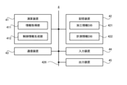
- FIG. 11 is a block diagram showing the configuration of the control server 4 in this embodiment.
- FIG. 12 shows the data structure of the processing information DB.
- FIG. 13 shows the data structure of the measurement information DB.
- FIG. 14 is a schematic diagram showing a specific example of a workpiece processed by the processing device and measured by the measuring device.
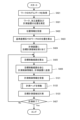
- FIG. 15 is a flowchart showing the flow of processing operations.
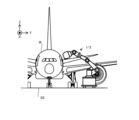
- FIG. 16 is a top view showing the positional relationship between the position measuring device and an aircraft, which is an example of a workpiece.
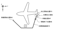
- FIG. 17 is a top view showing an aircraft as an example of the workpiece.
- FIG. 16 is a top view showing the positional relationship between the position measuring device and an aircraft, which is an example of a workpiece.
- FIG. 17 is a top view showing an aircraft as an example of the work
- FIG. 18 is a flowchart showing the flow of the operation of moving the processing head in step S112 of FIG.
- FIG. 19 is a top view showing an example of the fine adjustment area.
- FIG. 20 is a flowchart showing the flow of the measurement operation.
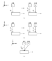
- FIGS. 21(a) to 21(c) is a cross-sectional view showing a processing device that processes a workpiece and a measuring device that measures the workpiece.
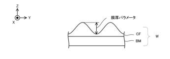
- FIG. 22 is a cross-sectional view showing a work including a base material and a film.
- FIG. 23 is a top view conceptually showing a non-processing area set on a workpiece.
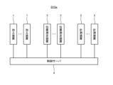
- FIG. 24 is a block diagram showing the configuration of a processing system in the first modification.
- FIG. 25(a) to 25(b) schematically shows an example of the usage of at least two processing devices 1 and the usage of at least two measuring devices 2.
- FIG. 26 is a block diagram showing the configuration of a processing device in a second modification.
- FIG. 27 is a block diagram showing the configuration of the control server in the third modification.
- each of the X-axis direction and the Y-axis direction is a horizontal direction (that is, a predetermined direction within a horizontal plane), and the Z-axis direction is a vertical direction (that is, a direction perpendicular to the horizontal plane). (and substantially in the vertical direction).
- the rotation directions (in other words, the tilt directions) around the X-axis, Y-axis, and Z-axis are referred to as the ⁇ X direction, the ⁇ Y direction, and the ⁇ Z direction, respectively.
- FIG. 1 is a block diagram showing the overall configuration of the processing system SYS in this embodiment.
- the processing system SYS includes a processing device 1, a measuring device 2, a position measuring device 3, and a control server 4.
- Each of the processing device 1, the measuring device 2, and the position measuring device 3 can communicate with the control server 4 via a communication network. That is, the control server 4 can communicate with each of the processing device 1, the measuring device 2, and the position measuring device 3 via the communication network.
- the communication network may typically include a wireless communication network.
- An example of a wireless communication network is a communication network compliant with the IMT (International Mobile Telecommunication) standard (for example, a communication network compliant with 4G, 5G, or 6G).
- Another example of a wireless communication network is a wireless LAN (Local Area Network).
- Another example of a wireless communication network is a communication network that can perform optical wireless communication.
- the processing device 1 is capable of processing a workpiece W, which is an example of an object, under the control of the control server 4.
- the workpiece W may be made of metal, an alloy (such as duralumin), a semiconductor (such as silicon), a resin, or a CFRP. It may be a composite material such as (Carbon Fiber Reinforced Plastic), a paint (as an example, a paint layer applied to a base material), a glass, or any other material. It may also be an object made of material.
- the processing device 1 may perform additional processing on the workpiece W. That is, the processing device 1 may perform additional processing to form a shaped object on the workpiece W.
- the processing device 1 may perform removal processing on the workpiece W. That is, the processing apparatus 1 may perform a removal process to remove a part of the workpiece W.
- the processing device 1 may perform marking processing to form a desired mark on the surface of the workpiece W.
- the processing device 1 may perform peening processing to change the surface characteristics of the workpiece W.
- the processing device 1 may perform a peeling process to peel off the surface of the workpiece W.
- the processing device 1 may perform a welding process to join one work W and another work W.
- the processing device 1 may perform a cutting process to cut the workpiece W.
- the processing device 1 may form a desired structure on the surface of the workpiece W by processing the workpiece W. However, the processing apparatus 1 may perform processing different from the processing for forming a desired structure on the surface of the workpiece W.
- the riblet structure may include a structure capable of reducing resistance (particularly, at least one of frictional resistance and turbulent flow frictional resistance) on the surface of the work W against fluid. For this reason, the riblet structure may be formed on the workpiece W having a member installed (in other words, located) in the fluid.
- the term "fluid” used herein means a medium (for example, at least one of gas and liquid) flowing toward the surface of the workpiece W. For example, if the surface of the workpiece W moves relative to the medium while the medium itself is stationary, this medium may be referred to as a fluid.
- the state in which the medium is stationary may mean a state in which the medium is not moving relative to a predetermined reference object (for example, the ground surface).
- An example of the workpiece W on which the riblet structure is formed is at least one of an aircraft, a windmill, an engine turbine, and a power generation turbine.
- the workpiece W becomes easier to move relative to the fluid. Therefore, the resistance that prevents movement of the workpiece W relative to the fluid is reduced, leading to energy savings.
- the resistance that impedes movement (typically, rotation) of the windmill is reduced, so that the efficiency of the windmill can be improved.
- the workpiece W is an engine turbine (for example, at least a part of the engine turbine)
- the resistance that prevents movement (typically, rotation) of the engine turbine is reduced; This leads to higher efficiency or energy saving of engine turbines.
- the workpiece W is a power generation turbine (for example, at least a part of the power generation turbine)
- the resistance that prevents movement (typically, rotation) of the power generation turbine is reduced; This leads to higher efficiency of power generation turbines (in other words, improved power generation efficiency).
- Processing equipment 1 is designed to meet Goal 13 of the Sustainable Development Goals (SDGs) led by the United Nations, ⁇ Take urgent action to combat climate change and its impacts.'' act ), which has the potential to contribute to "13.2.2 Reduction of Total Greenhouse Gas Emissions per Year", which is one of the goals set forth in 13.2.2.
- SDGs Sustainable Development Goals
- the measuring device 2 is capable of measuring the workpiece W under the control of the control server 4.
- the measuring device 2 may measure the work W to be processed by the processing device 1.
- the measuring device 2 may measure the workpiece W that has been processed by the processing device 1.
- the measuring device 2 may be capable of measuring the position of the workpiece W. That is, the measurement of the workpiece W by the measuring device 2 may include measurement of the position of the workpiece W.
- the measuring device 2 may be capable of measuring the shape (for example, three-dimensional shape) of the workpiece W. That is, the measurement of the work W by the measuring device 2 may include measurement of the shape of the work W.
- the processing system SYS can measure the workpiece W using the measuring device 2
- the processing system SYS may be referred to as a measurement system.
- the position measuring device 3 is capable of measuring the position of the object to be measured.
- the operation of measuring the position of the object to be measured may mean the operation of acquiring information that directly or indirectly indicates the position of the object to be measured as a measurement result.
- the object to be measured may include the workpiece W.
- the object to be measured may include the processing device 1.
- the object to be measured may include the measuring device 2. That is, the position measuring device 3 may be capable of measuring the position of at least one of the work W, the processing device 1, and the measuring device 2.
- the position measuring device 3 is capable of measuring the position of the object to be measured within a measurement coordinate system determined based on the position measuring device 3.
- a measurement coordinate system determined based on the position measuring device 3.
- the measurement coordinate system (that is, the reference coordinate system) has, for example, a horizontal direction in the X-axis direction and a Y-axis direction, a vertical direction in the Z-axis direction, and a position where the position measuring device 3 is arranged. It may be a coordinate system in which the position of the origin is set based on.
- the X-axis, Y-axis, and Z-axis may mean the X-axis, Y-axis, and Z-axis, respectively, in the measurement coordinate system (that is, the reference coordinate system).
- the position measuring device 3 may measure the position of the workpiece W in at least one of the X-axis direction, the Y-axis direction, the Z-axis direction, the ⁇ X direction, the ⁇ Y direction, and the ⁇ Z direction.
- the position measuring device 3 may measure the position of the processing device 1 in at least one of the X-axis direction, the Y-axis direction, the Z-axis direction, the ⁇ X direction, the ⁇ Y direction, and the ⁇ Z direction.
- the position measuring device 3 may measure the position of the measuring device 2 in at least one of the X-axis direction, the Y-axis direction, the Z-axis direction, the ⁇ X direction, the ⁇ Y direction, and the ⁇ Z direction.
- the position of the workpiece W measured by the position measuring device 3 (that is, the position of the workpiece W indicated by the measurement result of the position measuring device 3) may be used as a reference position that serves as a reference for the workpiece W. In this case, the position measuring device 3 may be considered to be measuring the reference position of the workpiece W.
- the position of the processing device 1 measured by the position measuring device 3 (that is, the position of the processing device 1 indicated by the measurement result of the position measuring device 3) may be used as a reference position on which the processing device 1 is based. . In this case, the position measuring device 3 may be considered to be measuring the reference position of the processing device 1.
- the position of the measuring device 2 measured by the position measuring device 3 (that is, the position of the measuring device 2 indicated by the measurement result of the position measuring device 3) may be used as a reference position that is a reference for the measuring device 2.
- the position measuring device 3 may be considered to be measuring the reference position of the measuring device 2.
- the control server 4 may be able to control the processing device 1.
- the control server 4 may control the processing device 1 so that the processing device 1 processes the workpiece W in a desired processing mode.
- the control server 4 receives position information indicating the measurement result of the position of at least one of the workpiece W, the processing device 1, and the measuring device 2 from the position measurement device 3 via the communication network. (that is, acquisition).
- the control server 4 may generate processing control information for controlling the processing device 1 based on the position information.
- the control server 4 may transmit (that is, output) the generated processing control information to the processing device 1 via the communication network.
- the processing device 1 may process the workpiece W based on processing control information transmitted from the control server 4.
- the control server 4 may manage the progress of processing the workpiece W by the processing device 1.
- the control server 4 may receive (that is, acquire) processing progress information regarding the progress of processing the workpiece W by the processing device 1 from the processing device 1 via the communication network.
- the processing device 1 may transmit (that is, output) processing progress information to the control server 4 via the communication network.
- the control server 4 may be able to control the measuring device 2.
- the control server 4 may control the measuring device 2 so that the measuring device 2 measures the workpiece W in a desired measurement manner.
- the control server 4 receives position information indicating the measurement result of the position of at least one of the workpiece W, the processing device 1, and the measuring device 2 from the measuring device 2 via the communication network ( In other words, it may be obtained (obtained).
- the control server 4 may generate measurement control information for controlling the measurement device 2 based on the position information.
- the control server 4 may transmit (that is, output) the generated measurement control information to the measurement device 2 via the communication network.
- the measuring device 2 may measure the workpiece W based on measurement control information transmitted from the control server 4.
- the control server 4 may acquire the measurement results of the workpiece W by the measuring device 2.
- the control server 4 may receive (that is, acquire) measurement result information regarding the measurement results of the workpiece W by the measurement device 2 from the measurement device 2 via the communication network.
- the measuring device 2 may transmit (that is, output) measurement result information to the control server 4 via the communication network.
- the control server 4 may control at least one of the processing device 1 and the measuring device 2 using the measurement result information acquired from the measuring device 2. For example, the control server 4 may generate processing control information based on the above-mentioned position information and measurement result information. For example, the control server 4 may generate measurement control information based on the position information and measurement result information described above.
- the processing system SYS includes at least one of the processing device 1, the measurement device 2, and the position measurement device 3, and at least one other of the processing device 1, the measurement device 2, and the position measurement device 3. It is not necessary to have
- the processing system SYS may include the processing device 1 and the measurement device 2, but may not include the position measurement device 3.
- the processing system SYS may include the measuring device 2 and the position measuring device 3, but may not include the processing device 1.
- the processing system SYS may include the processing device 1 and the position measurement device 3, but may not include the measurement device 2.
- FIG. 2 is a side view schematically showing the appearance of the processing device 1 in this embodiment.
- the processing device 1 may process the workpiece W placed on the support surface SS.
- the workpiece W may be placed on the support surface SS via a support member SM that supports the workpiece W on the support surface SS.
- the support member SM may be movable on the support surface SS.
- the support member SM may function as a transport device that transports the workpiece W to a desired position.
- the support member SM does not need to be movable on the support surface SS.
- the support member SM may be fixed to the support surface SS.
- the workpiece W may be placed directly on the support surface SS.
- the workpiece W may be placed on a self-propelled drive system or a movable stage. In this case, the position of the work W with respect to the support surface SS can be changed.
- the processing device 1 irradiates the workpiece W with processing light EL (that is, an energy beam having the form of light) in order to process the workpiece W. That is, the processing device 1 processes the workpiece W by irradiating the workpiece W with the processing light EL.
- the processing light EL may be any type of light as long as the workpiece W can be processed by being irradiated onto the workpiece W. In this embodiment, the description will proceed using an example in which the processing light EL is a laser beam. However, the processing light EL may be a different type of light from laser light. Further, the wavelength of the processing light EL may be any wavelength as long as the workpiece W can be processed by being irradiated with the processing light EL.
- the processing light EL may be visible light or invisible light (for example, at least one of infrared light, ultraviolet light, extreme ultraviolet light, etc.).
- the processing light EL may include pulsed light (for example, pulsed light whose emission time is picoseconds or less).
- the processing light EL may not include pulsed light. In other words, the processing light EL may be continuous light.
- the processing apparatus 1 includes a processing light source 11, a processing head 12, as shown in FIG. 2 and FIG. , a head drive system 13, and a control device 14.
- the processing light source 11 can generate processing light EL.
- the processing light source 11 emits the generated processing light EL toward the processing head 12 via a photoconductive member (not shown).
- Examples of the optical transmission member include at least one of an optical fiber and a light pipe.
- the processing head 12 irradiates the work W with the processing light EL emitted from the processing light source 11.
- the processing head 12 includes a processing optical system 121.
- the processing head 12 irradiates the workpiece W with processing light EL via the processing optical system 121. That is, the processing optical system 121 is an optical system for irradiating the workpiece W with the processing light EL. For this reason, the processing optical system 121 may be referred to as an irradiation optical system.
- the processing optical system 121 may include a focus optical element 1211.
- the focus optical element 1211 may be able to change the convergence position of the processing light EL.
- the focus optical element 1211 may be able to change the convergence position of the processing light EL in the direction along the optical axis AX of the processing optical system 121. Since the optical axis AX of the processing light EL typically intersects the surface of the workpiece W, the focus optical element 1211 can change the convergence position of the processing light EL in the direction intersecting the surface of the workpiece W. good.
- the head drive system 13 moves the processing head 12. For this reason, the head drive system 13 may be referred to as a moving device. Specifically, the head drive system 13 moves the processing head 12 relative to the workpiece W. In order to move the processing head 12, the head drive system 13 includes a self-propelled drive system 131, an arm drive system 132, and a fine movement drive system 133. However, the head drive system 13 may not include at least one of the self-propelled drive system 131, the arm drive system 132, and the fine movement drive system 133.
- the self-propelled drive system 131 is movable on the support surface SS that supports or arranges the workpiece W.
- the self-propelled drive system 131 is capable of self-propelled on the support surface SS that supports or arranges the workpiece W.
- the self-propelled drive system 131 moves the processing head 12 (that is, changes the position of the processing head 12) by self-propelled on the support surface SS.
- the arm drive system 132 is a drive system that can function as a robot arm that moves the processing head 12 (that is, changes the position of the processing head 12).
- the fine movement drive system 133 is also a drive system that moves the processing head 12 (that is, changes the position of the processing head 12).
- Each of the self-propelled drive system 131, the arm drive system 132, and the fine movement drive system 133 moves the processing head 12 along at least one of the X-axis direction, the Y-axis direction, the Z-axis direction, the ⁇ X direction, the ⁇ Y direction, and the ⁇ Z direction. move it.
- the self-propelled drive system 131 is self-propelled on the support surface SS.
- the support surface SS is typically a surface along the XY plane. Therefore, in the following description, an example will be described in which the self-propelled drive system 131 can move the processing head 12 along each of the X-axis direction and the Y-axis direction.
- the arm drive system 132 can move the processing head 12 along each of the X-axis direction, Y-axis direction, Z-axis direction, ⁇ X direction, ⁇ Y direction, and ⁇ Z direction. I will explain about it. Note that moving the processing head 12 along at least one of the ⁇ X direction, ⁇ Y direction, and ⁇ Z direction means changing the posture of the processing head 12 around at least one of the X axis, Y axis, and Z axis. They may be considered equivalent.
- moving the processing head 12 along at least one of the ⁇ X direction, the ⁇ Y direction, and the ⁇ Z direction is equivalent to rotating the processing head 12 around at least one of the X axis, the Y axis, and the Z axis.
- the support surface SS may be a surface inclined with respect to the XY plane, or may be a non-planar surface.
- the processing head 12 moves, the positional relationship between the processing head 12 and the workpiece W changes. Furthermore, when the positional relationship between the workpiece W and the processing head 12 changes, the positional relationship between the workpiece W and the processing optical system 121 provided in the processing head 12 changes. Furthermore, when the positional relationship between the workpiece W and the processing head 12 changes, the irradiation position of the processing light EL on the workpiece W changes. Therefore, moving the processing head 12 is equivalent to changing the irradiation position of the processing light EL on the workpiece W.
- the control device 14 controls the operation of the processing device 1.
- the control device 14 controls the processing light source 11, processing head 12, and head drive system included in the processing device 1 to process the workpiece W in a desired processing mode based on processing control information transmitted from the control server 4. At least one of 13 may be controlled. Further, the control device 14 may monitor the progress of machining the workpiece W by the machining device 1 and generate machining progress information regarding the progress of the machining. The control device 14 may transmit the generated processing progress information to the control server 4.
- the control device 14 may include, for example, a calculation device and a storage device.
- the arithmetic device may include, for example, at least one of a CPU (Central Processing Unit) and a GPU (Graphics Processing Unit).
- the storage device may include, for example, memory.
- the control device 14 functions as a device that controls the operation of the processing device 1 by a calculation device executing a computer program.
- This computer program is a computer program for causing the arithmetic device to perform (that is, execute) the operation to be performed by the control device 14, which will be described later. That is, this computer program is a computer program for causing the control device 14 to function so as to cause the processing device 1 to perform the operations described below.
- the computer program executed by the arithmetic device may be recorded in a storage device (that is, a recording medium) included in the control device 14, or may be stored in any storage device built into the control device 14 or externally attachable to the control device 14. It may be recorded on a medium (for example, a hard disk or a semiconductor memory). Alternatively, the computing device may download the computer program to be executed from a device external to the control device 14 via a network interface.
- a storage device that is, a recording medium
- the computing device may download the computer program to be executed from a device external to the control device 14 via a network interface.
- the control device 14 may control the emission mode of the processing light EL by the processing head 12.
- the injection mode may include, for example, at least one of the intensity of the processing light EL and the emission timing of the processing light EL.
- the emission mode is, for example, the light emission time of the pulsed light, the light emission period of the pulsed light, and the ratio of the length of the light emission time of the pulsed light to the light emission period of the pulsed light. (so-called duty ratio).
- the control device 14 may control the manner in which the processing head 12 is moved by the head drive system 13.
- the movement mode may include, for example, at least one of a movement amount, a movement speed, a movement direction, and a movement timing (movement timing).
- the control device 14 does not need to be provided inside the processing device 1.
- the control device 14 may be provided outside the processing device 1 as a server or the like.
- the control device 14 and the processing device 1 may be connected via a wired and/or wireless network (or a data bus and/or a communication line).
- a wired network for example, a network using a serial bus type interface represented by at least one of IEEE1394, RS-232x, RS-422, RS-423, RS-485, and USB may be used.
- a network using a parallel bus interface may be used.
- a network using an interface compliant with Ethernet typified by at least one of 10BASE-T, 100BASE-TX, and 1000BASE-T may be used.
- a network using radio waves may be used.
- An example of a network using radio waves is a network compliant with IEEE802.1x (for example, at least one of a wireless LAN and Bluetooth (registered trademark)).
- a network using infrared rays may be used.
- a network using optical communication may be used as the wireless network.
- the control device 14 and the processing device 1 may be configured to be able to transmit and receive various information via a network.
- control device 14 may be able to transmit information such as commands and control parameters to the processing device 1 via a network.
- the processing device 1 may include a receiving device that receives information such as commands and control parameters from the control device 14 via the network.
- the processing device 1 may include a transmitting device that transmits information such as commands and control parameters to the control device 14 via the network (that is, an output device that outputs information to the control device 14). good.
- a first control device that performs some of the processing performed by the control device 14 is provided inside the processing device 1, while a second control device that performs another part of the processing performed by the control device 14 is provided inside the processing device 1.
- the control device may be provided outside the processing device 1. Note that the control device 14 or the second control device provided outside the processing device 1 may be provided in a location different from the facility (for example, a hangar) where the processing device 1 is used.
- An arithmetic model that can be constructed by machine learning may be implemented in the control device 14 by the arithmetic device executing a computer program.
- An example of a calculation model that can be constructed by machine learning is a calculation model that includes a neural network (so-called artificial intelligence (AI)).
- learning the computational model may include learning parameters (eg, at least one of weights and biases) of the neural network.
- the control device 14 may control the operation of the processing device 1 using the calculation model.
- the operation of controlling the operation of the processing device 1 may include the operation of controlling the operation of the processing device 1 using a calculation model.
- the control device 14 may be equipped with an arithmetic model that has been constructed by offline machine learning using teacher data.
- the calculation model installed in the control device 14 may be updated by online machine learning on the control device 14.
- the control device 14 uses a calculation model installed in a device external to the control device 14 (that is, a device provided outside the processing device 1). The operation of the processing device 1 may be controlled by using the processing device 1.
- the recording medium for recording the computer program executed by the control device 14 includes CD-ROM, CD-R, CD-RW, flexible disk, MO, DVD-ROM, DVD-RAM, DVD-R, DVD+R, and DVD.
- At least one of optical disks such as RW, DVD+RW and Blu-ray (registered trademark), magnetic media such as magnetic tape, magneto-optical disks, semiconductor memories such as USB memory, and any other arbitrary medium capable of storing programs is used. It's okay to be hit.
- the recording medium may include a device capable of recording a computer program (for example, a general-purpose device or a dedicated device in which a computer program is implemented in an executable state in the form of at least one of software and firmware).
- each process or function included in the computer program may be realized by a logical processing block that is realized within the control device 14 when the control device 14 (that is, a computer) executes the computer program, or It may be realized by hardware such as a predetermined gate array (FPGA (Field Programmable Gate Array), ASIC (Application Specific Integrated Circuit)) included in the control device 14, or a logical processing block. and some of the hardware It may also be realized in a mixed format with partial hardware modules that realize the elements.
- FPGA Field Programmable Gate Array
- ASIC Application Specific Integrated Circuit
- the processing device 1 may include a power source.
- the processing device 1 may include a power source disposed on the cart 1311 of the self-propelled drive system 131.
- the processing device 1 may operate using electric power supplied from a power source.
- the processing light source 11 may generate the processing light EL using electric power supplied from a power source.
- the head drive system 13 may move the processing head 12 using electric power supplied from a power source.
- the power source may be rechargeable.
- the power source may be capable of non-contact charging (wireless charging).
- the head drive system 13 includes a self-propelled drive system 131, an arm drive system 132, and a fine movement drive system 133. Therefore, below, the self-propelled drive system 131, the arm drive system 132, and the fine movement drive system 133 will be explained in order.
- FIG. 4 is a cross-sectional view showing the configuration of the self-propelled drive system 131.
- the self-propelled drive system 131 includes a truck 1311 and a motor 1312.
- the trolley 1311 is a platform to which wheels are attached.
- the trolley 1311 is placed on the support surface SS.
- the wheels of the trolley 1311 can be rotated using the power of a motor 1312.
- the trolley 1311 can move on the support surface SS using the power of the motor 1312 driven under the control of the control device 14. That is, the trolley 1311 can self-propel on the support surface SS using the power of the motor 1312.
- the self-propelled drive system 131 is capable of self-propelled on the support surface SS. That is, since the support surface SS is a surface along the XY plane as described above, the self-propelled drive system 131 is capable of self-propelled along at least one of the X-axis direction and the Y-axis direction.
- the "state where the self-propelled drive system 131 self-propels on the support surface SS" referred to here means that the self-propelled drive system 131 uses the power generated by the self-propelled drive system 131 itself to move on the support surface SS. It may also mean a state of movement.
- An arm drive system 132 is mounted on the cart 1311. Specifically, the arm drive system 132 is attached (that is, fixed) to the truck 1311 (in the example shown in FIG. 4, on the upper surface of the truck 1311). Therefore, when the truck 1311 moves, the arm drive system 132 also moves. That is, the self-propelled drive system 131 moves together with the arm drive system 132. Furthermore, a fine movement drive system 133 is connected to the arm drive system 132. Specifically, a fine movement drive system 133 is attached to the arm drive system 132 (that is, it is fixed). Therefore, when the cart 1311 moves, the fine movement drive system 133 also moves. In other words, the self-propelled drive system 131 moves together with the fine movement drive system 133.
- the processing head 12 is connected to the fine movement drive system 133. Specifically, the processing head 12 is attached (that is, fixed) to the fine movement drive system 133. Therefore, when the cart 1311 moves, the processing head 12 also moves. That is, the self-propelled drive system 131 moves together with the processing head 12. Therefore, the self-propelled drive system 131 can function as a moving device that moves the processing head 12 by self-propelled. The self-propelled drive system 131 can function as a moving device that changes the position of the processing head 12.
- FIG. 4 is a cross-sectional view showing the configuration of the arm drive system 132.
- the arm drive system 132 includes a pedestal 1320.
- the frame 1320 is connected to the self-propelled drive system 131 (specifically, the truck 1311).
- the pedestal 1320 is attached (that is, fixed) to the trolley 1311.
- One end of a robot arm 1321 is attached to the pedestal 1320.
- a pedestal 1320 supports a robot arm 1321.
- the robot arm 1321 includes a plurality of arm members 1322.
- the plurality of arm members 1322 are movably connected via at least one joint member 1323.
- the robot arm 1321 may be a manipulator with degrees of freedom in three or more axes. Therefore, the arm drive system 132 may function as a robot having a so-called vertical multi-joint structure.
- the arm drive system 132 is not limited to a robot having a vertical multi-joint structure.
- the arm drive system 132 may function as a polar coordinate robot, a cylindrical coordinate robot, a Cartesian coordinate robot, or a parallel link robot having a horizontal multi-joint structure.
- the joint member 1323 has one arm member 1322 connected to the joint member 1323, and the other arm member 1322 connected to the joint member 1323 having one drive axis (for example, a rotation axis around the X axis, At least two arm members 1322 may be connected so as to be rotatable around at least one of a rotation axis around the Y-axis and a rotation axis around the Z-axis.
- the joint member 1323 has one arm member 1322 connected to the joint member 1323, and the other arm member 1322 connected to the joint member 1323 having one drive axis (for example, a movement axis along the X axis). , a movement axis along the Y-axis, and a movement axis along the Z-axis).
- FIG. 4 shows an example in which the arm drive system 132 includes four actuators 1324 corresponding to four joint members 1323.
- the arm drive system 132 includes four actuators 1324 corresponding to four joint members 1323.
- at least one arm member 1322 moves. Therefore, at least one arm member 1322 is movable with respect to the workpiece W. That is, at least one arm member 1322 is movable so that the relative positional relationship between at least one arm member 1322 and the workpiece W is changed.
- a fine movement drive system 133 is connected to the robot arm 1321. Specifically, the fine movement drive system 133 is connected to one arm member 1322 located farthest from the pedestal 1320 among the plurality of arm members 1322 (that is, it is attached or fixed). ).
- one arm member 1322 to which the fine movement drive system 133 is attached will be referred to as a tip arm member 1325.
- the fine movement drive system 133 may be directly attached to the distal arm member 1325, or may be indirectly attached to the distal arm member 1325 via another member.
- the tip arm member 1325 may be referred to as a connection member to which the fine movement drive system 133 is connected.
- the tip arm member 1325 moves relative to the pedestal 1320. That is, when the tip arm member 1325 moves, the relative position between the pedestal 1320 and the tip arm member 1325 changes. As a result, the fine movement drive system 133 attached to the distal arm member 1325 also moves. Therefore, the arm drive system 132 can move the fine movement drive system 133. Specifically, the arm drive system 132 can move the fine movement drive system 133 relative to the workpiece W. The arm drive system 132 can move the fine movement drive system 133 so that the relative positional relationship between the fine movement drive system 133 and the workpiece W is changed.
- the arm drive system 132 can function as a moving device that moves the processing head 12.
- the arm drive system 132 can function as a moving device that changes the position of the processing head 12.
- the tip arm member 1325 of the robot arm 1321 may be referred to as a movable part.
- FIG. 5 is a sectional view showing the configuration of the fine movement drive system 133.
- the fine movement drive system 133 includes a support member 1331, a support member 1332, an air spring 1333, a damper member 1334, and a drive member 1335.
- the support member 1331 is connected to the arm drive system 132. Specifically, the support member 1331 is attached (that is, fixed) to the tip arm member 1325 of the arm drive system 132. The support member 1332 is attached to the processing head 12.
- the support member 1331 and the support member 1332 are coupled (in other words, connected or connected) via an air spring 1333, a damper member 1334, and a drive member 1335. That is, the air spring 1333, the damper member 1334, and the drive member 1335 are each attached to the support members 1331 and 1332 so as to connect the support members 1331 and 1332. Since the arm drive system 132 is attached to the support member 1331 and the processing head 12 is attached to the support member 1332, each of the air spring 1333, the damper member 1334, and the drive member 1335 is substantially connected to the arm drive system 132. and processing head 12 may be considered to be attached to support members 1331 and 1332.
- the air spring 1333 applies elastic force due to the pressure of gas (air as an example) to at least one of the support members 1331 and 1332.
- the air spring 1333 applies elastic force due to gas pressure to at least one of the arm drive system 132 and the processing head 12 via at least one of the support members 1331 and 1332.
- the air spring 1333 applies elastic force due to gas pressure to at least one of the arm drive system 132 and the processing head 12 along the direction in which the support member 1331 and the support member 1332 are lined up (for example, the Z-axis direction). may be given to
- Gas is supplied to the air spring 1333 from a gas supply device 13361 via a pipe 13362 and a valve 13363 in order to impart elastic force due to gas pressure.
- the control device 14 controls at least one of the gas supply device 13361 and the valve 13363 based on the measurement result of the pressure gauge 1336 that measures the pressure of the gas inside the air spring 1333.
- the air spring 1333 may support the weight of the processing head 12 using elastic force under the control of the control device 14.
- the air spring 1333 may function as a dead weight canceller that cancels the dead weight of the processing head 12.
- the air spring 1333 uses elastic force under the control of the control device 14 to reduce (in other words, dampen) vibrations transmitted between the arm drive system 132 and the processing head 12 via the fine movement drive system 133. ) may be done.
- the damper member 1334 applies elastic force caused by a factor different from air pressure to at least one of the support members 1331 and 1332.
- the damper member 1334 applies elastic force caused by a factor different from air pressure to at least one of the arm drive system 132 and the processing head 12 via at least one of the support members 1331 and 1332.
- the damper member 1334 may apply elastic force to at least one of the arm drive system 132 and the processing head 12 along the direction in which the support member 1331 and the support member 1332 are lined up (for example, the Z-axis direction). .
- the damper member 1334 may support the weight of the processing head 12 using elastic force. Similarly to the air spring 1333, the damper member 1334 may utilize elastic force to reduce vibrations transmitted between the arm drive system 132 and the processing head 12 via the fine movement drive system 133.
- damper member 1334 may be any member as long as it can impart elastic force.
- damper member 1334 may include a compression spring coil.
- damper member 1334 may include a leaf spring.
- the driving member 1335 is capable of generating driving force under the control of the control device 14.
- the driving member 1335 can apply the generated driving force to at least one of the supporting members 1331 and 1332.
- the drive member 1335 can apply the generated drive force to at least one of the arm drive system 132 and the processing head 12 via at least one of the support members 1331 and 1332.
- the driving member 1335 may have any configuration as long as it can generate driving force.
- the driving member 1335 may have a configuration capable of electrically generating driving force.
- the driving member 1335 may have a configuration that can generate a driving force magnetically.
- FIG. 5 shows an example in which the drive member 1335 is a voice coil motor (VCM) that can electrically generate a driving force.
- VCM voice coil motor
- the driving member 1335 may move at least one of the support members 1331 and 1332 using driving force under the control of the control device 14.
- the drive member 1335 may move at least one of the arm drive system 132 and the processing head 12 by using a drive force to move at least one of the support members 1331 and 1332 under the control of the control device 14.
- the drive member 1335 may change the relative position of the arm drive system 132 and the processing head 12 by moving at least one of the arm drive system 132 and the processing head 12 using the driving force.
- the drive member 1335 may change the relative position of the arm drive system 132 and the processing head 12 under the control of the control device 14 based on the measurement results of the position measurement device 1337 included in the fine movement drive system 133.
- the position measuring device 1337 measures the relative position between the arm drive system 132 and the processing head 12.
- the position measuring device 1337 may be an encoder including a detection section 13371 attached to the support member 1331 and a scale section 13372 attached to the support member 1332.
- the measurement result of the position measuring device 1337 includes information regarding the relative positions of the support member 1331 and the support member 1332.
- the control device 14 can appropriately specify the relative position of the arm drive system 132 and the processing head 12. As a result, the control device 14 can appropriately change the relative position between the arm drive system 132 and the processing head 12 based on the measurement result of the position measurement device 1337.
- the drive member 1335 changes the relative position between the arm drive system 132 and the processing head 12 under the control of the control device 14 (typically, by moving the processing head 12 with respect to the arm drive system 132). , the processing head 12 may be moved relative to the workpiece W.
- the driving member 1335 may move the processing head 12 (that is, may drive it) so that the relative positional relationship between the processing head 12 and the workpiece W is changed.
- the support member 1332 to which the processing head 12 is attached is moved by the driving member 1335, the support member 1332 may be referred to as a movable part.
- the fine movement drive system 133 is moved by the arm drive system 132, at least some of the components constituting the fine movement drive system 133 may also be referred to as movable parts.
- the drive member 1335 changes the relative position of the arm drive system 132 and the processing head 12 by using driving force under the control of the control device 14, thereby causing slight movement between the arm drive system 132 and the processing head 12. Vibration transmitted via drive system 133 may be reduced.
- a device that actively reduces vibration using an elastic member such as an air spring 1333 and a drive member 1335 may be referred to as an active vibration isolator.
- the fine movement drive system 133 may be referred to as an active vibration isolator.
- An active vibration isolator may be referred to as an Active Vibration Isolation System (AVIS).
- the arm drive system 132 moves the processing head 12 with a smaller movement stroke than the self-propelled drive system 131.
- the self-propelled drive system 131 moves the processing head 12 with a larger movement stroke than the arm drive system 132.
- the movement stroke may mean the maximum amount of movement in one direction.
- the arm drive system 132 may move the processing head 12 with the same or larger movement stroke than the self-propelled drive system 131.
- the movement accuracy (in other words, movement resolution) of the processing head 12 by the arm drive system 132 is higher than the movement accuracy of the processing head 12 by the self-propelled drive system 131.
- the movement accuracy of the processing head 12 by the self-propelled drive system 131 is lower than the movement accuracy of the processing head 12 by the arm drive system 132.
- the movement accuracy (movement resolution) may mean a limit value of the fineness of movement (for example, minimum movement amount).
- the movement accuracy of the processing head 12 by the arm drive system 132 may be the same as the movement accuracy of the processing head 12 by the self-propelled drive system 131, or may be lower.
- the fine movement drive system 133 moves the processing head 12 with a smaller movement stroke than the arm drive system 132.
- the arm drive system 132 moves the processing head 12 with a larger movement stroke than the fine movement drive system 133.
- the fine movement drive system 133 may move the processing head 12 with the same or larger movement stroke than the arm drive system 132.
- the movement accuracy of the processing head 12 by the fine movement drive system 133 is higher than the movement accuracy of the processing head 12 by the arm drive system 132. In other words, the movement accuracy of the processing head 12 by the arm drive system 132 is lower than the movement accuracy of the processing head 12 by the fine movement drive system 133.
- the movement accuracy of the processing head 12 by the fine movement drive system 133 may be the same as the movement accuracy of the processing head 12 by the arm drive system 132, or may be lower.
- the processing system SYS may position the processing head 12 with respect to the workpiece W using the self-propelled drive system 131.
- the processing system SYS uses the arm drive system 132 to The processing head 12 may be aligned with respect to the workpiece W with finer or higher accuracy than 131.
- the processing system SYS uses the fine movement drive system 133 to move the processing head 12 further than the arm drive system 132.
- the processing head 12 may be aligned with respect to the workpiece W with fine or high precision.
- the machining system SYS uses the fine movement drive system 133 to maintain the desired positional relationship between the workpiece W and the machining head 12 (for example, when the distance between the workpiece W and the machining head 12 is The processing head 12 may be aligned with respect to the workpiece W so that the position of the processing head 12 is maintained constant.
- the processing head 12 since the processing head 12 is moved by the self-propelled drive system 131, the arm drive system 132, and/or the fine movement drive system 133, the processing head 12 may be referred to as a movable part.
- FIG. 6 is a side view schematically showing the appearance of the measuring device 2 in this embodiment.
- the measuring device 2 may measure the workpiece W placed on the support surface SS.
- the measuring device 2 includes a measuring head 22, a head drive system 23, a control device 24, as shown in FIG. 6 and FIG. 7, which is a block diagram showing the overall configuration of the measuring device 2. Equipped with.
- the measurement head 22 measures the workpiece W.
- the measurement head 22 may measure the position of the workpiece W.
- the measurement head 22 may measure the shape (for example, three-dimensional shape) of the workpiece W.
- the measurement head 22 may have any configuration as long as it can measure the workpiece W.
- the measurement head 22 may be a non-contact measuring device that can measure the work W without coming into contact with the work W.
- the measurement head 22 may be a contact-type measurement device that can measure the workpiece W by coming into contact with the workpiece W.
- An example of a non-contact measuring device is an optical measuring device that optically measures the workpiece W.
- An example of a contact-type measuring device is a probe-type measuring device that measures the work W by bringing a probe into contact with the work W.
- An example of an optical measuring device is a measuring device (for example, an imaging device such as a camera) that measures the workpiece W by capturing an image of the workpiece W.
- An example of an optical measuring device is a measuring device that uses a pattern projection method.
- a measuring device using a pattern projection method may measure the workpiece W by projecting slit light onto the surface of the workpiece W and measuring the shape of the projected slit light.
- An example of an optical measuring device is a measuring device that uses a pattern projection method.
- a measuring device using a pattern projection method may measure the work W by projecting pattern light onto the surface of the work W and measuring the shape of the projected pattern light.
- An example of an optical measuring device is a measuring device that uses interferometry.
- a measuring device using interferometry may measure the workpiece W by measuring an interference pattern between an object beam passing through the workpiece W and a reference beam not passing through the workpiece W.
- An example of an optical measuring device is a measuring device that uses the time-of-flight method.
- a measurement device that uses the time-of-flight method projects measurement light onto the surface of the workpiece W, and measures the distance from the measurement device to the workpiece W based on the time it takes for the projected measurement light to return from the workpiece W to the measurement device.
- the work W may be measured by performing the operation of measuring the distance at a plurality of positions on the work W.
- optical measurement devices include moire topography method (specifically, grating irradiation method or grating projection method), holographic interference method, autocollimation method, stereo method, astigmatism method, critical angle method, and Examples include measuring devices that use at least one of the knife edge methods.
- the head drive system 23 moves the measurement head 22.
- the head drive system 23 may be referred to as a moving device.
- the head drive system 23 moves the measurement head 22 relative to the workpiece W.
- the head drive system 23 includes a self-propelled drive system 231, an arm drive system 232, and a fine movement drive system 233.
- the head drive system 23 does not need to include at least one of the self-propelled drive system 231, the arm drive system 232, and the fine movement drive system 233.
- the configuration of the self-propelled drive system 231 included in the measuring device 2 may be the same as the configuration of the self-propelled drive system 131 included in the processing device 1.
- the self-propelled drive system 231 includes a truck 2311 and a motor 2312.
- the features of the trolley 2311 may be the same as those of the trolley 1311 shown in FIG.
- the characteristics of motor 2312 may be the same as the characteristics of motor 1312 shown in FIG. Therefore, in the above description of the self-propelled drive system 131, the words "cart 1311, motor 2312, and processing head 12" are replaced with the words "cart 2311, motor 2312, and measurement head 22," respectively. It can be used as an explanation. Therefore, a detailed explanation of the self-propelled drive system 231 will be omitted.
- the configuration of the arm drive system 232 included in the measuring device 2 may be the same as the configuration of the arm drive system 132 included in the processing device 1.
- the arm drive system 232 includes a pedestal 2320, a robot arm 2321 (specifically, a plurality of robot arms including a tip arm member 2325), arm member 2322, a plurality of joint members 2323, and a plurality of actuators 2324).
- the features of pedestal 2320 may be the same as those of pedestal 1320 shown in FIG.
- the features of the robot arm 2321 may be the same as the features of the robot arm 1321 shown in FIG.
- arm member 2322 may be the same as the features of arm member 1322 shown in FIG.
- the features of joint member 2323 may be the same as the features of joint member 1323 shown in FIG.
- the features of actuator 2324 may be the same as those of actuator 1324 shown in FIG.
- the features of the distal arm member 2325 may be the same as the features of the distal arm member 1325 shown in FIG. Therefore, the above description of the arm drive system 132 includes the pedestal 1320, robot arm 1321, arm member 1322, joint member 1323, actuator 1324, tip arm member 1325, self-propelled drive system 131, fine movement drive system 133, and processing head 12.
- the configuration of the fine movement drive system 233 included in the measuring device 2 may be the same as the configuration of the fine movement drive system 133 included in the processing device 1. That is, the fine movement drive system 233 may have the configuration shown in FIG. 5, which shows the configuration of the fine movement drive system 133. Therefore, detailed explanation of the fine movement drive system 233 will be omitted.
- Each of the self-propelled drive system 231, the arm drive system 232, and the fine movement drive system 233 moves the measurement head 22 along at least one of the X-axis direction, the Y-axis direction, the Z-axis direction, the ⁇ X direction, the ⁇ Y direction, and the ⁇ Z direction. move it.
- the self-propelled drive system 231 is self-propelled on the support surface SS.
- the support surface SS is typically a surface along the XY plane. Therefore, in the following description, an example will be described in which the self-propelled drive system 231 can move the measurement head 22 along each of the X-axis direction and the Y-axis direction.
- the arm drive system 232 can move the measurement head 22 along each of the X-axis direction, Y-axis direction, Z-axis direction, ⁇ X direction, ⁇ Y direction, and ⁇ Z direction. I will explain about it. Note that moving the measurement head 22 along at least one of the ⁇ X direction, ⁇ Y direction, and ⁇ Z direction means changing the posture of the measurement head 22 around at least one of the X axis, Y axis, and Z axis. They may be considered equivalent.
- moving the measurement head 22 along at least one of the ⁇ X direction, the ⁇ Y direction, and the ⁇ Z direction is equivalent to rotating the measurement head 22 around at least one of the X axis, the Y axis, and the Z axis. It may be assumed that
- the measurement head 22 When the measurement head 22 moves, the positional relationship between the measurement head 22 and the workpiece W changes. When the positional relationship between the workpiece W and the measurement head 22 changes, the measurement area of the measurement head 22 moves on the workpiece W. Therefore, moving the measurement head 22 is equivalent to moving the measurement area on the workpiece W. Note that since the measurement head 22 is moved by the self-propelled drive system 231, the arm drive system 232, and/or the fine movement drive system 233, the measurement head 22 may be referred to as a movable part.
- the control device 24 controls the operation of the measuring device 2. For example, the control device 24 controls at least one of the measurement head 22 and the head drive system 23 included in the measurement device 2 so as to measure the workpiece W in a desired measurement manner based on measurement control information transmitted from the control server 4. One may be controlled. Further, the control device 24 may transmit measurement result information regarding the measurement results of the workpiece W by the measurement device 2 to the control server 4.
- the control device 24 may include, for example, a calculation device and a storage device.
- the arithmetic device may include, for example, at least one of a CPU and a GPU.
- the storage device may include, for example, memory.
- the control device 24 functions as a device that controls the operation of the measuring device 2 by a calculation device executing a computer program.
- This computer program is a computer program for causing the arithmetic device to perform (that is, execute) the operation to be performed by the control device 24, which will be described later.
- this computer program is a computer program for causing the control device 24 to function so as to cause the measuring device 2 to perform the operations described below.
- the computer program executed by the arithmetic device may be recorded in a storage device (that is, a recording medium) included in the control device 24, or may be stored in any storage device built into the control device 24 or externally attachable to the control device 24. It may be recorded on a medium (for example, a hard disk or a semiconductor memory). Alternatively, the computing device may download the computer program to be executed from a device external to the control device 24 via a network interface.
- a storage device that is, a recording medium
- the computing device may download the computer program to be executed from a device external to the control device 24 via a network interface.
- the control device 24 may control the manner in which the measurement head 22 measures the workpiece W.
- the measurement aspect may include, for example, at least one of a measurement position and a measurement time.
- the control device 24 may control the manner in which the measurement head 22 is moved by the head drive system 23.
- the movement mode may include, for example, at least one of a movement amount, a movement speed, a movement direction, and a movement timing (movement timing).
- the control device 24 does not need to be provided inside the measuring device 2.
- the control device 24 may be provided outside the measurement device 2 as a server or the like.
- the control device 24 and the measurement device 2 may be connected via a wired and/or wireless network (or a data bus and/or a communication line).
- a wired network for example, a network using a serial bus type interface represented by at least one of IEEE1394, RS-232x, RS-422, RS-423, RS-485, and USB may be used.
- a network using a parallel bus interface may be used.
- a network using an interface compliant with Ethernet typified by at least one of 10BASE-T, 100BASE-TX, and 1000BASE-T may be used.
- a network using radio waves may be used.
- An example of a network using radio waves is a network compliant with IEEE802.1x (for example, at least one of a wireless LAN and Bluetooth (registered trademark)).
- a network using infrared rays may be used.
- a network using optical communication may be used as the wireless network.
- the control device 24 and the measurement device 2 may be configured to be able to transmit and receive various information via a network.
- control device 24 may be able to transmit information such as commands and control parameters to the measurement device 2 via a network.
- the measuring device 2 may include a receiving device that receives information such as commands and control parameters from the control device 24 via the network.
- the measuring device 2 may include a transmitting device that transmits information such as commands and control parameters to the control device 24 via the network (that is, an output device that outputs information to the control device 24). good.
- a first control device that performs some of the processing performed by the control device 24 is provided inside the measuring device 2
- a second control device that performs another part of the processing performed by the control device 24 is provided inside the measurement device 2.
- a control device may be provided outside the measuring device 2.
- An arithmetic model that can be constructed by machine learning may be implemented in the control device 24 by the arithmetic device executing a computer program.
- An example of a computational model that can be constructed by machine learning is a computational model that includes a neural network (so-called artificial intelligence (AI)).
- learning the computational model may include learning parameters (eg, at least one of weights and biases) of the neural network.
- the control device 24 may control the operation of the measuring device 2 using the calculation model. That is, the operation of controlling the operation of the measuring device 2 may include the operation of controlling the operation of the measuring device 2 using a calculation model.
- the control device 24 may be equipped with an arithmetic model that has been constructed by offline machine learning using teacher data.
- the calculation model installed in the control device 24 may be updated by online machine learning on the control device 24.
- the control device 24 uses a calculation model installed in a device external to the control device 24 (that is, a device provided outside the measurement device 2). The operation of the measuring device 2 may be controlled by using the same.
- the recording medium for recording the computer program executed by the control device 24 includes CD-ROM, CD-R, CD-RW, flexible disk, MO, DVD-ROM, DVD-RAM, DVD-R, DVD+R, and DVD.
- At least one of optical disks such as RW, DVD+RW and Blu-ray (registered trademark), magnetic media such as magnetic tape, magneto-optical disks, semiconductor memories such as USB memory, and any other arbitrary medium capable of storing programs is used. It's okay to be hit.
- the recording medium may include a device capable of recording a computer program (for example, a general-purpose device or a dedicated device in which a computer program is implemented in an executable state in the form of at least one of software and firmware).
- each process or function included in the computer program may be realized by a logical processing block that is realized within the control device 24 when the control device 24 (that is, a computer) executes the computer program, or It may be realized by hardware such as a predetermined gate array (FPGA, ASIC) included in the control device 24, or a logical processing block and a partial hardware module that realizes some hardware elements coexist. It may be realized in a format.
- a logical processing block that is realized within the control device 24 when the control device 24 (that is, a computer) executes the computer program
- hardware such as a predetermined gate array (FPGA, ASIC) included in the control device 24, or a logical processing block and a partial hardware module that realizes some hardware elements coexist. It may be realized in a format.
- the measuring device 2 may include a power source.
- the measuring device 2 may include a power source placed on the trolley 2311 of the self-propelled drive system 231.
- the measuring device 2 may operate using power supplied from a power source.
- the measurement unit 221 may measure the workpiece W using power supplied from a power source. Processing light EL may also be generated.
- the head drive system 23 may move the measurement head 22 using power supplied from a power source.
- the power source may be rechargeable.
- the power source may be capable of non-contact charging (wireless charging).
- the position measuring device 3 can measure the position of at least one of the workpiece W, the processing device 1, and the measuring device 2.
- the position measuring device 3 may have any configuration as long as it can measure the position of at least one of the workpiece W, the processing device 1, and the measuring device 2.
- the position measuring device 3 measures the position of a measurement object including at least one of the workpiece W, the processing device 1, and the measuring device 2 using the measurement light ML.
- the position measuring device 3 may measure the position of the measurement target by irradiating the measurement light ML onto the measurement target and detecting the return light of the measurement light ML from the measurement target.
- the return light of the measurement light ML from the measurement target may include at least one of the reflected light of the measurement light ML by the measurement target and the scattered light of the measurement light ML by the measurement target.
- the position measuring device 3 may be placed at a position away from the measuring object. That is, the position measuring device 3 may be placed at a position away from at least one of the workpiece W, the processing device 1, and the measuring device 2. In this case, the position measuring device 3 may irradiate the measurement light ML onto the measurement target from a position away from the measurement target. The position measuring device 3 may detect the return light of the measurement light ML from the measurement target at a position away from the measurement target.
- the position measuring device 3 may irradiate the measurement light ML toward a desired measurement target portion of the measurement target and detect the measurement light ML from the desired measurement target portion of the measurement target.
- a reflector capable of reflecting the measurement light ML typically, capable of retroreflection
- the position measuring device 3 irradiates the measurement light ML toward the reflector, and Alternatively, the measurement light ML may be detected. In either case, the position measuring device 3 can measure the position of a desired measurement target portion of the measurement target.
- the position measuring device 3 may irradiate the measurement light ML toward each of the plurality of measurement target parts of the measurement target and detect the measurement light ML from the plurality of measurement target parts of the measurement target. In this case, the position measuring device 3 can measure the positions of a plurality of measurement target parts of the measurement target.
- FIG. 9 is a front view showing the external appearance of the position measuring device 3.
- FIG. 10 is a block diagram showing the configuration of the position measuring device 3. As shown in FIG.
- the position measuring device 3 includes a pedestal 310 and a housing 320.
- the pedestal 310 is a pedestal that supports the housing 320.
- the pedestal 310 may be arranged, for example, on the support surface SS on which the workpiece W, the processing device 1, and the measuring device 2 are arranged.
- the pedestal 310 may be placed on the support surface SS via a support member (not shown), or may be placed directly on the support surface SS.
- Housing 320 is a member in which optical assembly 330 shown in FIG. 10 is housed.
- Housing 320 may be rotatable around a predetermined rotation axis. In the example shown in FIG. 9, the housing 320 is rotatable about a rotation axis along the Y-axis and a rotation axis along the Z-axis.
- the optical assembly 330 includes a measurement light source 331, a pointing beam source 332, a beam splitter 333, a beam splitter 334, a beam splitter 335, a mirror 336, an optical circuit 337, and a detector 338. Equipped with.
- the measurement light source 331 generates measurement light ML.
- a part of the measurement light ML generated by the measurement light source 331 is emitted from the exit port 321 formed in the housing 320 via beam splitters 334 and 335 and a mirror 336.
- the measurement light ML emitted from the exit port 321 is incident on the object to be measured.
- the position measuring device 3 may rotate the housing 320 so that the measurement light ML is incident on a desired measurement target portion of the measurement target.
- At least a portion of the measurement light ML reflected by the measurement object enters the optical assembly 330 via the exit port 321.
- the returned light RL that has entered the optical assembly 330 enters the detector 338 via the mirror 336 and the beam splitter 335.
- another part of the measurement light ML generated by the measurement light source 331 is generated by the beam splitter 334 and the optical circuit described in U.S. Patent Application Publication No. 2012/188557 (or U.S. Patent No. 4,733,606, etc.). 337 and enters a detector 338 .
- the position measuring device 3 transmits the detection result of the detector 338 to the control server 4 as position information indicating the measurement result of the position of at least one of the workpiece W, the processing device 1, and the measuring device 2.
- the control server 4 calculates the position of the measurement target based on the detection results of the measurement light ML and the return light RL by the detector 338.
- the control server 4 uses the optical heterodyne detection described in U.S. Patent Application Publication No. 2012/188557 (or U.S. Patent No. 4,733,606, etc.) to detect the measurement light ML and the return light by the detector 338.
- the position of the object to be measured is calculated based on the detection result of RL.
- Pointing beam source 332 generates pointing beam B.
- Pointing beam B is used to identify the position on the measurement object to which measurement light ML is directed.
- Pointing beam B may include visible light.
- Pointing beam B generated by pointing beam source 332 is emitted from exit port 321 formed in housing 320 via beam splitters 333 , 334 and 335 and mirror 336 .
- the pointing beam B emitted from the exit port 321 is incident on the object to be measured.
- the optical assembly 330 does not need to irradiate the measuring object with the pointing beam B.
- the position measuring device 3 is not limited to the measuring device including the laser radar system described in US Patent Application Publication No. 2012/188557.
- the position measuring device 3 may be a measuring device including a laser coordinate measuring device described in US Pat. No. 7,800,758 (for example, a measuring device using intensity-modulated measuring light).
- the position measuring device 3 may be a measuring device (for example, a measuring device using intensity-modulated measuring light) that includes an absolute distance meter described in US Pat. No. 6,847,436.
- FIG. 11 is a block diagram showing the configuration of the control server 4 in this embodiment.
- control server 4 may include a calculation device 41, a storage device 42, a communication device 43, an input device 44, and an output device 45.
- the arithmetic device 41, the storage device 42, the communication device 43, the input device 44, and the output device 45 may be connected via a data bus 46.
- the arithmetic device 41 includes, for example, at least one of a CPU and a GPU. Arithmetic device 41 reads a computer program. For example, the arithmetic device 41 may read a computer program stored in the storage device 42. For example, the arithmetic device 41 may read a computer program stored in a computer-readable, non-temporary recording medium using a recording medium reading device (not shown). The arithmetic device 41 may obtain (that is, may download or read) a computer program from a device (not shown) located outside the control server 4 via the communication device 43 . The arithmetic device 41 executes the loaded computer program.
- a logical functional block for executing the operations to be performed by the control server 4 is realized within the arithmetic unit 41.
- the arithmetic device 41 can function as a controller for realizing a logical functional block for executing the operations that the control server 4 should perform.
- a calculation model that can be constructed by machine learning may be implemented in the calculation device 41 by the calculation device 41 executing a computer program.
- An example of a computational model that can be constructed by machine learning is a computational model that includes a neural network (so-called artificial intelligence (AI)).
- learning the computational model may include learning parameters (eg, at least one of weights and biases) of the neural network.
- the calculation device 41 may use the calculation model to execute the operation that the control server 4 should perform.
- the calculation device 41 may be equipped with a calculation model that has been constructed by offline machine learning using teacher data. Further, the calculation model installed in the calculation device 41 may be updated by online machine learning on the calculation device 41.
- the calculation device 41 uses a calculation model installed in a device external to the calculation device 41 (that is, a device provided outside the control server 4).
- the control server 4 may also use the control server 4 to execute operations that should be performed.
- FIG. 11 shows an example of logical functional blocks implemented within the arithmetic unit 41.
- an information acquisition section 411 and a control information generation section 412 are implemented within the arithmetic device 41.
- the information acquisition unit 411 may receive (that is, acquire) processing progress information from the processing device 1 using the communication device 43 .
- the information acquisition unit 411 may receive (that is, acquire) measurement result information from the measurement device 2 using the communication device 43 .
- the information acquisition unit 411 may receive (that is, acquire) position information from the position measurement device 3 using the communication device 43 .
- the control information generation unit 412 may generate processing control information and measurement control information based on the position information.
- the storage device 42 can store desired data.
- the storage device 42 may temporarily store a computer program executed by the arithmetic device 41.
- the storage device 42 may temporarily store data that is temporarily used by the arithmetic device 41 while the arithmetic device 41 is executing a computer program.
- the storage device 42 may store data that the control server 4 stores for a long period of time.
- the storage device 42 may include at least one of a RAM (Random Access Memory), a ROM (Read Only Memory), a hard disk device, a magneto-optical disk device, an SSD (Solid State Drive), and a disk array device. good. That is, the storage device 42 may include a non-temporary recording medium.
- the storage device 42 may store a processing information DB 421 and a measurement information DB 422.
- the processing information DB 421 is a database for storing information regarding the processing device 1.
- the measurement information DB 422 is a database for storing information regarding the measurement device 2.
- the processing information DB 421 includes a plurality of processing information records 4210.
- Each processing information record 4210 may include device identification information 4211, time information 4212, and processing device information 4213.
- the device identification information 4211 is information for uniquely identifying the processing device 1.
- Time information 4212 is information indicating the time corresponding to processing device information 4213.
- the processing device information 4213 is information regarding the processing device 1.
- the processing device information 4213 may include device position information indicating the position of the processing device 1 at the time indicated by the time information 4212.
- the processing device information 4213 may include processing progress information acquired by the information acquisition unit 411.
- the machining progress information may include information regarding the degree of progress of the machining operation at the time indicated by the time information 4212. That is, the machining progress information may include information regarding the ratio of steps completed by the machining device 1 (that is, the progress rate) with respect to the entire process of machining operations to be performed by the machining device 1.
- the machining progress information may include information regarding a machining completion area of the workpiece W where machining by the machining device 1 has been completed.
- the machining progress information may include information regarding an unfinished area of the workpiece W where machining by the machining device 1 has not yet been completed.
- the processing device information 4213 includes information regarding the time during which the processing device 1 can operate using the power stored in the power source (that is, the remaining amount of the power source). You can stay there.
- the information acquisition unit 411 acquires information necessary for constructing the processing information DB 421 (for example, at least one of device identification information 4211, time information 4212, and processing device information 4213) from the processing device 1. It may be received (that is, acquired) from.
- the measurement information DB 421 includes a plurality of measurement information records 4220.
- Each measurement information record 4220 may include device identification information 4221, time information 4222, and measurement device information 4223.
- the device identification information 4221 is information for uniquely identifying the measuring device 2.
- Time information 4222 is information indicating the time corresponding to measuring device information 4223.
- the measuring device information 4223 is information regarding the measuring device 2.
- the measuring device information 4223 may include measurement result information indicating the measurement result by the measuring device 2 at the time indicated by the time information 4222 (that is, the measurement result information acquired by the information acquisition unit 411).
- the measurement device information 4223 may include measurement progress information.
- the measurement progress information may include information regarding the progress of the measurement operation at the time indicated by the time information 4222. That is, the measurement progress information may include information regarding the ratio of steps completed by the measuring device 2 (that is, the progress rate) to the entire steps of the measuring operation that the measuring device 2 should perform.
- the measurement progress information may include information regarding a measurement completion area of the workpiece W where measurement by the measurement device 2 has been completed.
- the measurement progress information may include information regarding unfinished measurement areas of the workpiece W where measurement by the measuring device 2 has not yet been completed.
- the measuring device information 4223 includes information regarding the time during which the measuring device 2 can operate using the power stored in the power source (that is, the remaining amount of the power source). You can stay there.
- the information acquisition unit 411 acquires information necessary for constructing the measurement information DB 422 (for example, at least one of device identification information 4221, time information 4222, and measurement device information 4223) from the measurement device 2. It may be received (that is, acquired) from.
- the storage device 42 may store a processing information DB 421 having an arbitrary data format (in other words, an arbitrary file format). For example, the storage device 42 may store the processing information DB 421 as tabular data (file) shown in FIG. Similarly, the storage device 42 may store the measurement information DB 422 having any data format (in other words, any file format). For example, the storage device 42 may store the measurement information DB 422 as tabular data (file) shown in FIG. 13.
- the communication device 43 is capable of communicating with each of the processing device 1, the measuring device 2, and the position measuring device 3 via the communication network.
- the input device 44 is a device that accepts input of information to the control server 4 from outside the control server 4.
- the input device 44 may include an operating device (eg, at least one of a keyboard, a mouse, and a touch panel) that can be operated by a worker (eg, a user of the processing system SYS).
- the input device 44 may include a reading device capable of reading information recorded as data on a recording medium that can be externally attached to the control server 4.
- the input device 44 may include a receiving device capable of receiving information that a device external to the control server 4 transmits as data to the control server 4 via a communication network.
- the output device 45 is a device that outputs information to the outside of the control server 4.
- the output device 45 may output the information as an image.
- the output device 45 may include a display device (so-called display) capable of displaying an image indicating information desired to be output.
- the output device 45 may output the information as audio.
- the output device 45 may include an audio device (so-called speaker) that can output audio.
- the output device 45 may output information on paper. That is, the output device 45 may include a printing device (so-called printer) that can print desired information on paper.
- the output device 45 may output (for example, display) information stored in at least one of the processing information DB 421 and the measurement information DB 422.
- the output device 45 may display a table (for example, the table shown in FIG. 12) showing information stored in the processing information DB 421.
- the output device 45 may display a table (for example, the table shown in FIG. 13) showing information stored in the measurement information DB 422.
- control server 4 may analyze the information stored in at least one of the processing information DB 421 and the measurement information DB 422, and the output device 45 may output (for example, display) the analysis result.
- the output device 45 may display the analysis results in association with the work W.
- the output device 45 may display the analysis results in a display format in which the analysis results and the work W are associated (for example, a display format different from the display format using the table described above).
- the control server 4 analyzes the machining progress included in the machining information DB 421, and the output device 45 displays the machining information for each part of a display object that imitates a workpiece W (for example, an aircraft).
- the work W and the analysis results may be displayed in a display format in which progress rates are associated. That is, the output device 45 may display a heat map indicating the processing progress rate in association with the workpiece W. As a result, the user of the machining system SYS can intuitively recognize the machining progress rate of each part of the workpiece W.
- the processing device 1 may process a workpiece W that is larger than the processing device 1.
- the processing device 1 processes a workpiece W corresponding to at least a part of an aircraft.
- the processing device 1 may process at least a portion of an aircraft so as to form the above-mentioned riblet structure in at least a portion of the fuselage, main wing, horizontal stabilizer, and/or vertical stabilizer of the aircraft.
- the processing device 1 may process a workpiece W smaller than the processing device 1.
- the processing device 1 may process a workpiece W having the same size as the processing device 1.
- the measuring device 2 may measure a workpiece W that is larger than the measuring device 2.
- the measuring device 2 measures a workpiece W corresponding to at least a part of an aircraft.
- the measuring device 2 may measure at least a portion of the fuselage, main wing, horizontal stabilizer, and/or vertical stabilizer of the aircraft.
- the measuring device 2 may process a work W smaller than the measuring device 2.
- the measuring device 2 may process a work W having the same size as the measuring device 2.
- processing system SYS may perform the processing operation and measurement operation described below.
- FIG. 15 is a flowchart showing the overall flow of the machining operation.
- the control information generation unit 412 of the control server 4 acquires model data indicating a three-dimensional model of the workpiece W to be processed by the processing device 1 (step S411). That is, the control information generation unit 412 acquires model data indicating a three-dimensional model having the designed three-dimensional shape of the workpiece W to be processed by the processing apparatus 1 (step S411).
- An example of model data is CAD (Computer Aided Design) data.
- CAD data file formats include DWF (Design Web Format), DXF (Drawing Exchange Format), DWG, and STEP (Standard for the Exchange of Pr). Examples include at least one of product data) and STL (Stereolithography).
- the model data may be stored in the storage device 42 of the control server 4.
- the control information generation unit 412 may acquire the model data from the storage device 42.
- the model data may be stored in a storage device included in the control device 14 of the processing device 1. In this case, the control information generation unit 412 may acquire model data from the processing device 1.
- the model data may be stored in an external device different from the control server 4 and the processing device 1. In this case, the control information generation unit 412 may acquire model data from an external device.
- the position measuring device 3 measures the respective positions of the workpiece W, the processing device 1, and the measuring device 2 (step S311). However, in the machining operation, the position measuring device 3 does not necessarily have to measure the position of the measuring device 2.
- the position measuring device 3 may measure the positions of multiple measurement target parts of the workpiece W.
- the part to be measured may include a characteristic part of the workpiece W.
- the parts to be measured include a characteristic part of the main wing (e.g., tip), a characteristic part of the horizontal stabilizer (e.g., tip), a characteristic part of the vertical stabilizer (e.g., tip), and a characteristic part of the aircraft body. (e.g., a tip).
- the position measuring device 3 may measure the position of a single measurement target portion of the workpiece W. Note that when the position of the workpiece W can be changed, the position measuring device 3 sets at least a part of the mechanism that changes the position of the workpiece W as a measurement target part, and measures the position of the mechanism. good.
- the position measuring device 3 may measure the positions of a plurality of measurement target parts of the processing device 1.
- the part to be measured may include a characteristic part of the processing device 1.
- the part to be measured may include at least one of a characteristic part of the processing head 12, a characteristic part of the arm drive system 132, and a characteristic part of the self-propelled drive system 131.
- the position measuring device 3 may measure the position of a single measurement target portion of the processing device 1.
- the position measuring device 3 may measure the positions of a plurality of measurement target parts of the measuring device 2.
- the part to be measured may include a characteristic part of the measuring device 2.
- the part to be measured may include at least one of a characteristic part of the measurement head 22, a characteristic part of the arm drive system 232, and a characteristic part of the self-propelled drive system 231.
- the position measuring device 3 may measure the position of a single measurement target portion of the measuring device 2.
- the processing system SYS may include a plurality of position measuring devices 3.
- the first position measuring device 3 of the plurality of position measuring devices 3 may be aligned with the workpiece W so that it can measure the position of the first measurement target portion of the workpiece W. good.
- a second position measuring device 3 different from the first position measuring device 3 among the plurality of position measuring devices 3 measures the position of a second measurement target portion of the workpiece W that is different from the first measurement target portion. It may be aligned with respect to the workpiece W so that it can be measured. As a result, the processing system SYS can appropriately measure the positions of the plurality of measurement target portions of the workpiece W using the plurality of position measuring devices 3.
- the position measuring device 3 may measure the position of the workpiece W by irradiating the measurement light ML toward the reflector attached to the workpiece W as the object to be measured.
- the reflector may be attached to the workpiece W at a predetermined position.
- a plurality of reflectors may be attached to at least three predetermined locations on the work W, respectively.
- a first reflector may be mounted near the cockpit of the aircraft (e.g., near the tip of the aircraft)
- a second reflector may be mounted near the tip of the left wing of the aircraft
- a third reflector may be mounted near the tip of the aircraft's left wing. It may be attached near the tip of the right main wing.
- Other reflectors may be mounted at other locations on the aircraft. Note that the number of reflectors attached to the workpiece W may be three or more or three or less.
- the position measuring device 3 may measure the position of the processing device 1 by irradiating the measurement light ML toward the reflector attached to the processing device 1 as the object to be measured.
- the reflector may be attached to a predetermined position of the processing device 1.
- the reflector may be attached near the tip of the head drive system 13 included in the processing device 1 (for example, at a position where the processing head 12 is attached).
- a reflector may be attached to the processing head 12.
- the position measuring device 3 can appropriately measure the position of the processing head 12.
- a reflector may be attached to the self-propelled drive system 131. In this case, the position measuring device 3 can roughly measure the position of the processing head 12.
- the position measuring device 3 may measure the position of the measuring device 2 by irradiating the measuring light ML toward the reflector attached to the measuring device 2 as the object to be measured.
- the reflector may be attached to the measuring device 2 at a predetermined position.
- the reflector may be attached near the tip of the head drive system 23 included in the measuring device 2 (for example, at a position where the measuring head 22 is attached).
- a reflector may be attached to the measurement head 22.
- the position measuring device 3 can appropriately measure the position of the measurement head 22.
- a reflector may be attached to the self-propelled drive system 231. In this case, the position measuring device 3 can roughly measure the position of the measuring head 22.
- the measurement coordinate system determined based on the position measuring device 3 is used as the reference coordinate system that is the reference for the processing system SYS.
- the processing system SYS includes a plurality of position measuring devices 3
- a first measurement coordinate system determined based on the first position measuring device 3 of the plurality of position measuring devices 3 is used as a reference coordinate system.
- the second position measuring device 3 of the plurality of position measuring devices 3 detects the workpiece W, the processing device 1, and the measuring device within a second measurement coordinate system determined based on the second position measuring device 3. Measure each position of 2.
- the second position measuring device 3 cannot measure the respective positions of the workpiece W, the processing device 1, and the measuring device 2 in the reference coordinate system. I can't.
- the control server 4 uses the position information indicating the measurement results by the second position measurement device 3 (for example, the detection results of the measurement light ML and return light RL by the detector 338 shown in FIG. 10 described above).
- the respective positions of the workpiece W, the processing device 1, and the measuring device 2 in the reference coordinate system may not be calculated.
- one of the first and second position measuring devices 3 may measure the position of the other of the first and second position measuring devices 3. .
- the control server 4 uses the result of measuring the position of the other of the first and second position measuring devices 3 by one of the first and second position measuring devices 3 to provide at least part of the position information. You may also obtain it as In this case, the control server 4 determines the first position based on the measurement result of the position of the other of the first and second position measuring devices 3 by either one of the first and second position measuring devices 3. The relative positional relationship between the measuring device 3 and the second position measuring device 3 can be calculated.
- the control server 4 converts the position in the second measurement coordinate system to the first measurement coordinate system based on the relative positional relationship between the first position measurement device 3 and the second position measurement device 3. It can be converted to a position within the system (that is, a position within the reference coordinate system). That is, the control server 4 can appropriately calculate the positions of the plurality of measurement target parts of the workpiece W within the reference coordinate system using the position information acquired from each of the plurality of position measuring devices 3.
- the processing system SYS includes a plurality of position measuring devices 3, including a position measuring device 3 for measuring the position of the workpiece W, a position measuring device 3 for measuring the position of the processing device 1, and a measuring device 2.
- a position measuring device 3 for measuring the position may be separately provided. That is, the processing system SYS may include the position measuring device 3 that measures the position of the workpiece W but does not need to measure the positions of the processing device 1 and the measuring device 2.
- the processing system SYS may include a position measuring device 3 that measures the position of the processing device 1 but does not need to measure the positions of the workpiece W and the measuring device 2.
- the processing system SYS may include a position measuring device 3 that measures the position of the measuring device 2 but does not need to measure the positions of the work W and the processing device 1.
- the workpiece W may move during at least part of the period during which the machining operation is performed. That is, the position of the workpiece W within the reference coordinate system may be changed during at least part of the period during which the machining operation is performed.
- the information acquisition unit 411 of the control server 4 uses the communication device 43 to transmit position information indicating the measurement results of the respective positions of the workpiece W, processing device 1, and measuring device 2 in step S311. Receive (that is, acquire) from the device 3 (step S412).
- the control information generation unit 412 of the control server 4 uses the reference coordinates based on the model data acquired in step S411 and the position information acquired in step S412 (particularly the position information indicating the measurement result of the position of the workpiece W).
- the position of the workpiece W in the system is calculated (step S413).
- the control information generation unit 412 may calculate the position of the workpiece W in at least one of the X-axis direction, the Y-axis direction, and the Z-axis direction.
- the control information generation unit 412 may calculate the position of the work W (that is, the posture of the work W) in at least one of the ⁇ X direction, the ⁇ Y direction, and the ⁇ Z direction.
- the position information indicating the measurement result of the position of the work W indicates the position of the measurement target part of the work W whose position has been measured by the position measuring device 3; 3 does not indicate the position of the non-measurement target part whose position has not been measured. Therefore, the control information generation unit 412 can only calculate the position of a part of the workpiece W within the reference coordinate system by simply referring to the position information. In other words, the control information generation unit 412 cannot calculate the position of the remaining part of the workpiece W within the reference coordinate system. Therefore, the control information generation unit 412 performs a fitting process to place the same measurement target part of the three-dimensional model indicated by the model data at the position of the measurement target part of the workpiece W indicated by the position information in the reference coordinate system.
- the fitting process may include at least one of a process of translating the three-dimensional model, a process of enlarging or reducing the three-dimensional model, and a process of rotating the three-dimensional model.
- the fitting process may include a process of affine transforming the three-dimensional model.
- the process of affine transforming the three-dimensional model includes at least one of the following: a process of translating the three-dimensional model, a process of enlarging or reducing the three-dimensional model, a process of rotating the three-dimensional model, and a process of skew-transforming the three-dimensional model. It may contain one.
- the three-dimensional model of the workpiece W is placed at a position that is assumed to be the same as the position of the workpiece W within the reference coordinate system.
- a three-dimensional model of the workpiece W is placed in the reference coordinate system in a posture that is assumed to be the same as the posture of the workpiece W.
- the control information generation unit 412 uses the position of the three-dimensional model of the workpiece W within the reference coordinate system as the position of the workpiece W within the reference coordinate system. Specifically, the control information generation unit 412 calculates the position of the measurement target portion of the three-dimensional model of the work W as the position of the measurement target portion of the work W.
- control information generation unit 412 calculates the position of the non-measurement target portion of the three-dimensional model of the work W as the position of the non-measurement target portion of the work W. As a result, the control information generation unit 412 can generate map information indicating the workpiece W mapped within the reference coordinate system. That is, the control information generation unit 412 can generate map information indicating the position of each part of the workpiece W within the reference coordinate system. Note that the map information is information indicating the position of an object called the work W, and therefore may be referred to as work position information or object position information.
- control information generation unit 412 of the control server 4 allocates at least a part of the area of the workpiece W to the processing apparatus 1 as a target processing area to be processed by the processing apparatus 1 (step S414).
- the processing device 1 processes the target processing area assigned in step S414.
- the control information generation unit 412 may set the target machining area in the workpiece W based on the map information generated in step S413. For example, the control information generation unit 412 may set the position of the target processing area in the reference coordinate system. The control information generation unit 412 may set a single target machining area or may set a plurality of target machining areas. After that, when a single target machining area is set, the control information generation unit 412 may allocate the set target machining area to the machining device 1. When a plurality of target machining regions are set, the control information generation unit 412 may allocate at least one of the plurality of target machining regions to the machining device 1. That is, the control information generation unit 412 may allocate a plurality of target processing areas to the processing apparatus 1.
- the control information generation unit 412 of the control server 4 calculates the target movement path TR of the processing head 12 based on the map information generated in step S413 and the target processing area allocated in step S414 (step S415). If a plurality of target machining areas are assigned to the machining device 1 in step S414, the control information generation unit 412 generates map information and one target machining area that has not yet been machined among the plurality of target machining areas. Based on this, the target movement path TR of the processing head 12 is calculated (step S415).
- the target movement path TR in the processing operation includes a movement path for moving the processing head 12 toward a position where the target processing area assigned in step S414 can be processed.
- the target movement route TR may include a movement route along which the self-propelled drive system 131 moves. That is, the target movement path TR may include a movement path along which the self-propelled drive system 131 moves the processing head 12.
- FIG. 17 is a top view showing the workpiece W.
- the control information generation unit 412 may set (in other words, acquire) a movement start position MS corresponding to the starting point of the target movement route TR. That is, the control information generation unit 412 may set the movement start position MS at which the processing head 12 starts moving along the target movement path TR. For example, the control information generation unit 412 may set the movement start position MS based on the position information acquired in step S412. That is, the movement start position MS may be input based on position information. As an example, the control information generation unit 412 calculates the current position of the processing device 1 (for example, the current position of the processing head 12, the same applies hereinafter) based on the position information, and uses the calculated current position of the processing device 1 to start the movement. It may also be set to the position MS.
- the control information generation unit 412 calculates the current position of the processing device 1 (for example, the current position of the processing head 12, the same applies hereinafter) based on the position information, and uses the calculated current position of the processing device 1 to start the movement. It may also be set to the
- control information generation unit 412 may set a position different from the current position of the processing device 1 as the movement start position MS.
- the control information generation unit 412 may set the position of the charging station where the processing device 1 charges the power source as the movement start position MS. .
- the movement start position MS is at least one of the X, Y, and Z coordinates. May contain.
- the control information generation unit 412 may set (in other words, acquire) a movement end position ME corresponding to the end point of the target movement route TR. That is, the control information generation unit 412 may set the movement start position MS at which the processing head 12 ends its movement along the target movement path TR. For example, the control information generation unit 412 may set the movement end position ME based on the position of the target processing area allocated in step S414. As an example, the control information generation unit 412 may set the movement end position ME to a position where the processing head 12 can process the work W without the self-propelled drive system 131 moving the processing head 12.
- control information generation unit 412 may set the movement end position ME to a position where the processing head 12 can process the target processing area without the self-propelled drive system 131 moving the processing head 12.
- control information generation unit 412 may set the movement end position ME to a position where the distance between the workpiece W and the processing head 12 is less than the movement stroke of the processing head 12 by the arm drive system 132. good.
- control information generation unit 412 may set a position where the distance between the target processing area and the processing head 12 is less than the movement stroke of the processing head 12 by the arm drive system 132 as the movement end position ME.
- the movement end position ME may be set at a position a certain distance away from the workpiece W.
- the movement end position ME may include at least one of an X coordinate, a Y coordinate, and a Z coordinate.
- the operation of setting the movement end position ME based on the target machining area is equivalent to setting the movement end position ME based on the model data. may be considered equivalent to the action of setting .
- control information generation unit 412 may set the movement end position ME based on the movement start position MS.
- control information generation unit 412 may set a position that is a certain distance or more away from the movement start position MS as the movement end position ME.
- control information generation unit 412 may calculate the movement route from the movement start position MS to the movement end position ME as the target movement route TR.
- the control information generation unit 412 may calculate the movement route from the movement start position MS to the movement end position ME as the target movement route TR.
- the processing head 12 moves from the movement start position MS to the movement end position ME, which is the target position (that is, the destination), along the target movement path TR.
- the control information generation unit 412 may calculate a target movement path TR that does not interfere with other objects different from the processing device 1. That is, the control information generation unit 412 may calculate the target movement route TR that does not pass through areas where other objects are located. Specifically, the control information generation unit 412 specifies an area where another object is located based on the map information generated in step S413, and creates a target movement route TR that does not pass through (that is, avoids) the specified area. may be calculated. For example, the control information generation unit 412 may calculate the shortest target movement route TR that can ensure a predetermined distance or more between another object and the processing device 1.
- the control information generation unit 412 may calculate a target movement route TR that does not interfere with the workpiece W, as shown in FIG. That is, the control information generation unit 412 may calculate the target movement route TR that does not pass through the area where the workpiece W is located. Specifically, the control information generation unit 412 specifies the area where the workpiece W is located based on the map information generated in step S413, and creates a target movement route TR that does not pass through (that is, avoids) the specified area. It may be calculated. For example, the control information generation unit 412 may calculate the shortest target movement route TR that can ensure the distance between the workpiece W and the processing device 1 to be a predetermined distance or more.
- the control information generation unit 412 may calculate a target movement route TR that does not interfere with the measurement device 2, as shown in FIG. That is, the control information generation unit 412 may calculate the target movement route TR that does not pass through the area where the measuring device 2 is located. Specifically, the control information generation unit 412 identifies the area where the measuring device 2 is located based on the positional information acquired in step S412 (particularly the positional information indicating the measurement result of the position of the measuring device 2). , a target movement route TR that does not pass through (that is, avoids) the specified area may be calculated. For example, the control information generation unit 412 may calculate the shortest target movement route TR that can ensure the distance between the measuring device 2 and the processing device 1 to be a predetermined distance or more.
- the control information generation unit 412 may calculate a target movement route TR that does not interfere with the moving measuring device 2. That is, the control information generation unit 412 may calculate the target movement route TR in which the measuring device 2 and the processing device 1 are not located at the same position at the same time. The control information generation unit 412 may calculate a target movement route TR that does not collide with the measuring device 2 and the processing device 1. Specifically, the control information generation unit 412 calculates a target movement path TR of the processing device 1 that does not interfere with the moving measurement device 2, based on a target movement path TR of the measurement device 2 calculated by a measurement operation described later. You may.
- the control information generation unit 412 may calculate a target movement route TR that does not interfere with the obstacle. That is, the control information generation unit 412 may calculate the target movement route TR that does not pass through an area where an obstacle is located. For example, the control information generation unit 412 may calculate the shortest target movement route TR that can ensure a distance between the obstacle and the processing device 1 at least a predetermined distance.
- control information generation unit 412 calculates at least one of the posture of the arm drive system 132 in the processing apparatus 1 and the movable range of the processing head 12 with respect to the self-propelled drive system 131. One may be considered.
- the control server 4 may typically obtain information regarding obstacles before the machining operation is performed. For example, before a machining operation is started, an obstacle detection device detects an obstacle, and the control server 4 acquires the detection result by the obstacle detection device as information regarding the obstacle. good. Alternatively, the operator may input information regarding the obstacle into the control server 4 using the input device 44. Note that the control server 4 may acquire information regarding obstacles during at least part of the period during which the machining operation is performed. For example, the control server 4 may acquire information regarding obstacles before calculating the target travel route TR.
- the control information generation unit 412 corresponds to the position of the machining head 12 at the time when the machining head 12 actually starts machining the target machining area after completing movement along the target movement path TR.
- the machining start position PS may be set (in other words, acquired).
- the control information generation unit 412 may set the machining start position PS based on the position of the target machining area assigned in step S414.
- the control information generation unit 412 may set a desired position of the target processing area as the processing start position PS.
- the processing start position PS may include at least one of an X coordinate, a Y coordinate, and a Z coordinate.
- control information generation unit 412 may set the processing start position PS based on the movement start position MS.
- control information generation unit 412 may set the processing start position PS to a position that is a certain distance or more away from the movement start position MS.
- the processing head 12 When the processing start position PS is set, the processing head 12 is moved from the movement start position MS to the first target position (that is, the first objective) by the self-propelled drive system 131 along the target movement path TR. The robot moves to the movement end position ME. Thereafter, the processing head 12 is moved by the arm drive system 132 from the movement end position ME to the processing start position PS, which is the second target position (that is, the second destination). In this case, on the movement path of the machining head 12 by the self-propelled drive system 131 and the arm drive system 132, the movement end position ME is considered to be located between the movement start position MS and the machining start position PS. good.
- the length of the movement path from the movement start position MS to the movement end position ME may be longer than the length of the movement path from the movement end position ME to the processing start position PS. That is, the amount of movement of the processing head 12 by the self-propelled drive system 131 (that is, the amount of change in the position of the processing head 12, hereinafter the same) may be larger than the amount of movement of the processing head 12 by the arm drive system 132.
- the control information generation unit 412 may set the movement end position ME based on the machining start position PS. For example, the control information generation unit 412 may set a position that is a certain distance away from the processing start position PS in the direction away from the workpiece W as the movement end position ME. As a result, the possibility that the processing device 1 that has finished moving along the target movement path TR will come into contact with the workpiece W by mistake is reduced. In this case, the control information generation unit 412 may set the movement end position ME to a position that is a distance shorter than the movement stroke of the processing head 12 by the arm drive system 132 from the processing start position PS. As a result, in order to move the processing head 12 from the movement end position ME to the processing start position PS, the self-propelled drive system 131 does not need to move the processing head 12.
- the control information generation unit 412 may set (in other words, acquire) a standby position WP where the processing head 12 temporarily waits after completing movement along the target movement path TR. .
- the control information generation unit 412 selects a position that is a certain distance away from the machining start position PS in the direction away from the workpiece W and a certain distance away from the movement end position ME in the direction towards the workpiece W. It may also be set to the standby position PS. In this case, the distance between the processing start position PS and the standby position WP is shorter than the distance between the processing start position PS and the movement end position ME.
- the standby position WP may include at least one of an X coordinate, a Y coordinate, and a Z coordinate.
- the processing head 12 When the standby position WP is set, the processing head 12 is moved from the movement start position MS to the first target position (that is, the first destination) by the self-propelled drive system 131 along the target movement route TR. ) to the movement end position ME. Thereafter, the processing head 12 is moved by the arm drive system 132 from the movement end position ME to the standby position WP, which is the second target position (that is, the second destination). Thereafter, the processing head 12 is moved by the arm drive system 132 from the standby position WP to the processing start position PS, which is the third target position (that is, the third destination).
- the movement end position ME may be considered to be located between the movement start position MS and the standby position WP on the movement path of the processing head 12 by the self-propelled drive system 131 and the arm drive system 132.
- the standby position WP may be considered to be located between the movement end position ME and the processing start position PS.
- control information generation unit 412 then generates processing control information (step S416).
- the control information generation unit 412 may generate processing control information for controlling the head drive system 13 to move the processing head 12 along the target movement path TR calculated in step S415.
- the control information generation unit 412 may generate processing control information for controlling the processing apparatus 1 to process the target processing area allocated in step S414.
- control information generation unit 412 transmits the processing control information to the processing device 1 using the communication device 43.
- the control device 14 of the processing device 1 receives the processing control information (step S111).
- the control device 14 of the processing apparatus 1 controls the head drive system 13 to move the processing head 12 based on the processing control information received in step S111 (step S112).
- the self-propelled drive system 131 moves the processing head 12 along the target movement path TR. That is, the self-propelled drive system 131 moves the processing head 12 along the target movement path TR by self-propelling on the support surface SS along the target movement path TR.
- the arm drive system 132 may further move the processing head 12 located at the movement end position ME to the standby position WP.
- the arm drive system 132 may further move the machining head 12 located at the movement end position ME or the standby position WP to the machining start position PS.
- control device 14 controls the movement of the processing head 12 based on processing control information generated by the control server 4. In this case, it may be assumed that the control server 4 controls the movement of the processing head 12.
- Step S113 After the processing head 12 finishes moving along the target movement region TR (that is, after the processing head 12 reaches the movement end position ME), the processing device 1 processes the assigned target processing region in step S414. (Step S113).
- the machining system SYS repeats the same operation until it determines to end the machining operation (step S417: Yes). For example, if it is necessary to machine a target machining area different from the target machining area machined in step S113, the machining system SYS may determine not to end the machining operation (step S417: No ). If there is no need to process a target machining area different from the target machining area processed in step S113, the machining system SYS may determine to end the machining operation (step S417: Yes). If it is necessary to process another workpiece W different from the workpiece W processed in step S113, the processing system SYS may determine not to end the processing operation (step S417: No). If there is no need to process a workpiece W different from the workpiece W processed in step S113, the processing system SYS may determine to end the processing operation (step S417: Yes).
- the machining system SYS may perform the operations from step S415 to step S113 again. That is, the control server 4 calculates a target movement path TR including a movement path for moving the processing head 12 toward a position where the processing device 1 can process a new target processing area to be processed next (step S415). . After that, the control server 4 generates processing control information (step S416). After that, the processing device 1 receives processing control information from the control server 4 (step S111). Thereafter, the processing apparatus 1 controls the head drive system 13 to move the processing head 12 based on the processing control information (step S112). After that, the processing device 1 processes a new target processing area to be processed next by the processing device 1 (step S113).
- step S417: No the machining system SYS may perform the operations from step S311 to step S113 again.
- the position measuring device 3 may measure the respective positions of the workpiece W, the machining device 1, and the measuring device 2 again (step S417: No). S311).
- the control server 4 may calculate the position of the work W in the reference coordinate system again (step S413). In this case, even if at least one of the shape and position of the workpiece W changes as the workpiece W is processed, the control server 4 can accurately calculate the position of the workpiece W. As a result, the control server 4 can appropriately calculate the target movement path TR even if at least one of the shape and position of the workpiece W changes as the workpiece W is processed.
- the power source may be charged after the processing operation is completed.
- the machining device 1 may move to a charging station where the machining device 1 charges the power source, and may charge the power source.
- FIG. 18 is a flowchart showing the flow of the operation of moving the processing head 12 in step S112 of FIG.
- the processing system SYS does not have to perform the operation shown in FIG.
- control device 14 of the processing apparatus 1 controls the head drive system 13 to move the processing head 12 based on the processing control information received in step S111 of FIG. S1121). As a result, the processing head 12 moves along the target movement path TR.
- step S1121 the control device 14 moves the processing head 12 using the self-propelled drive system 131. That is, the control device 14 controls the self-propelled drive system 131 to move the processing head 12 based on the processing control information. As a result, the self-propelled drive system 131 moves along the target movement path TR together with the processing head 12. That is, the processing head 12 moves along the target movement path TR.
- control device 14 of the processing device 1 may determine whether or not the processing head 12 has entered the fine adjustment area AA (step S1122).
- the fine adjustment area AA may be an area determined based on the workpiece W.
- the fine adjustment area AA may be an area that includes the workpiece W, as shown in FIG. 19(a).
- the fine adjustment area AA may be an area where the distance from the work W is equal to or less than a predetermined first distance, as shown in FIG. 19(b).
- the fine adjustment area AA may be an area determined independently of the workpiece W.
- the information regarding the fine adjustment area AA (for example, information regarding the position of the fine adjustment area AA within the reference coordinate system) may be information known to the control device 14.
- the control device 14 may acquire position information indicating the measurement result of the position of the processing device 1 from the position measuring device 3. Thereafter, the control device 14 may determine whether the processing head 12 has entered the fine adjustment area AA based on the acquired position information and information regarding the fine adjustment area AA. Specifically, the control device 14 calculates the current position of the processing head 12 based on the position information, and the calculated current position of the processing head 12 is set in the fine adjustment area where the information regarding the fine adjustment area AA indicates the position. It may be determined whether or not it is included in AA. If it is determined that the current position of the processing head 12 is included in the fine adjustment area AA, the control device 14 may determine that the processing head 12 has entered the fine adjustment area AA.
- the control device 14 determines whether the processing head 12 has entered the fine adjustment area AA. The processing is performed based on the position of the workpiece W calculated in step S413 of FIG. 15 and the positional information acquired in step S412 of FIG. The distance between the head 12 and the workpiece W may be calculated. The control device 14 may determine that the processing head 12 has entered the fine adjustment area AA when the calculated distance is shorter than the first distance that defines the fine adjustment area AA.
- the movement end position ME where the self-propelled drive system 131 ends the movement of the processing head 12 is typically set at a position a certain distance away from the workpiece W.
- the fine adjustment area AA determined based on the workpiece W may be considered to be an area determined based on the movement end position ME that is a certain distance away from the workpiece W.
- the fine adjustment area AA may be an area where the distance from the movement end position ME is equal to or less than a predetermined second distance.
- the fine adjustment area AA may be set by the control server 4 that sets the movement end position ME.
- the control device 14 controls the processing head 12 and the processing head 12 based on the position information indicating the measurement result of the position of the processing device 1.
- the distance from the movement end position ME may also be calculated.
- the control device 14 may determine that the processing head 12 has entered the fine adjustment area AA when the calculated distance is shorter than the second distance that defines the fine adjustment area AA.
- At least one of the first distance and the second distance may be set in consideration of the movable range of the processing head 12 based on the self-propelled drive system 131.
- step S1122 the processing head 12 has not entered the fine adjustment area AA (for example, the distance between the processing head 12 and the movement end position ME is not shorter than the second distance). If it is determined that (step S1122: No), the control device 14 continues to move the processing head 12 along the target movement path TR using the self-propelled drive system 131 (step S1121).
- Step S1122 when it is determined that the processing head 12 has entered the fine adjustment area AA (for example, the distance between the processing head 12 and the movement end position ME is shorter than the second distance) as a result of the determination in step S1122. (Step S1122: Yes), the control device 14 moves the processing head 12 along the target movement path TR using the self-propelled drive system 131 (Step S1123). However, in step S1123, the control device 14 newly acquires position information indicating the measurement result of the position of the processing device 1 by the position measurement device 3 from the position measurement device 3, and combines the newly acquired position information and processing control information. Based on this, the processing head 12 is moved along the target movement path TR.
- the control device 14 can calculate the accurate current position of the processing device 1 (that is, the accurate current position of the processing head 12) based on the position information. Therefore, compared to the case where position information is not used, the control device 14 can appropriately move the processing head 12 along the target movement path TR. Therefore, the processing device 1 can prevent a collision between the processing device 1 and the workpiece W due to the control device 14 not being able to accurately grasp the current position of the processing device 1.
- the control device 14 moves the processing head 12 along the target movement path based on position information indicating the measurement result of the position of the processing device 1 by the position measurement device 3. It may be moved along the TR.
- the position measuring device 3 may continue to measure the position of the processing device 1 while the processing head 12 is moving.
- the position measuring device 3 may continue to measure the position of the processing device 1 at predetermined intervals while the processing head 12 is moving. In this case, the control device 14 will not be unable to grasp the current position of the processing device 1. Therefore, the control device 14 can appropriately move the processing head 12 along the target movement path TR.
- the self-propelled drive system 131 moves the processing head 12 with higher movement accuracy than the movement accuracy of the processing head 12 before the processing head 12 enters the fine adjustment area AA. may be moved. That is, until the processing head 12 enters the fine adjustment area AA, the self-propelled drive system 131 moves the processing head 12 with the first movement accuracy, and after the processing head 12 enters the fine adjustment area AA, The self-propelled drive system 131 may move the processing head 12 with a second movement accuracy higher than the first movement accuracy.
- the processing device 1 can prevent a collision between the processing device 1 and the workpiece W due to low movement accuracy of the processing head 12 at a position close to the workpiece W.
- control device 14 uses the self-propelled drive system 131 to move the processing head 12 along the target movement path TR based on the position information until the processing head 12 reaches the movement end position ME (step S1124: No). and continues to move (step S1123).
- step S1124: Yes the control device 14 causes the processing head 12 that has reached the movement end position ME to move to the standby position WP or the processing start position PS.
- the arm drive system 132 may be controlled (step S1125).
- step S1125 the control device 14 may move the processing head 12 based on position information indicating the measurement result of the position of the processing device 1 by the position measuring device 3.
- the control device 14 can move from the movement end position ME to the standby position based on the position information.
- the processing head 12 can be appropriately moved to the position WP or the processing start position PS.
- the processing device 1 can prevent a collision between the processing device 1 and the work W due to the controller 14 not being able to accurately grasp the current position of the processing device 1.
- control device 14 may control the arm drive system 132 to move the processing head 12 during at least part of the period in which the self-propelled drive system 131 is moving the processing head 12.
- the processing head 12 is moved to the standby position WP or the processing start position PS. The time required is reduced.
- FIG. 20 is a flowchart showing the overall flow of the measurement operation.
- step S421 the control information generation unit 412 of the control server 4 acquires model data indicating a three-dimensional model of the workpiece W to be measured by the measuring device 2 (step S421).
- the operation in step S421 may be the same as the operation in step S411 in FIG. 15 described above.
- the position measuring device 3 measures the respective positions of the workpiece W, the processing device 1, and the measuring device 2 (step S321).
- the operation in step S321 may be the same as the operation in step S311 in FIG. 15 described above. However, in the measurement operation, the position measuring device 3 does not necessarily need to measure the position of the processing device 1.
- the information acquisition unit 411 of the control server 4 uses the communication device 43 to receive position information indicating the measurement results of the respective positions of the workpiece W, the processing device 1, and the measuring device 2 in step S321 from the position measuring device 3. Receive (that is, acquire) (step S422).
- control information generation unit 412 of the control server 4 uses the reference coordinates based on the model data acquired in step S421 and the position information acquired in step S412 (in particular, the position information indicating the measurement result of the position of the workpiece W).
- the position of the workpiece W in the system is calculated (step S423).
- the operation in step S423 may be the same as the operation in step S413 in FIG. 15 described above.
- step S424 the control information generation unit 412 of the control server 4 allocates at least a part of the area of the workpiece W to the measuring device 2 as a target measurement area to be measured by the measuring device 2 (step S424).
- the measuring device 2 measures the target measurement area allocated in step S424.
- the operation in step S424 may be the same as the operation in step S414 in FIG. 15 described above. Specifically, the explanation regarding the operation of step S414 in FIG. 15 described above can be explained by replacing the words "processing device 1" and "target machining area” with the words “measuring device 2" and “target measurement area”, respectively. , can be used as an explanation regarding the operation of step S424.
- the control information generation unit 412 of the control server 4 calculates the target movement route TR of the measurement head 22 based on the map information generated in step S423 and the target measurement area allocated in step S424 (step S425).
- the target movement path TR in the measurement operation includes a movement path for moving the measurement head 22 toward a position where the target measurement area assigned in step S424 can be measured.
- the target movement route TR may include a movement route along which the self-propelled drive system 231 moves. That is, the target movement path TR may include a movement path along which the self-propelled drive system 231 moves the measurement head 22.
- step S425 may be the same as the operation in step S415 in FIG. 15 described above.
- the explanation regarding the operation of step S415 in FIG. 15 described above includes “processing device 1,” “processing head 12,” “self-propelled drive system 131,” “arm drive system 132,” and “measuring device 2.”
- machining operation “target machining area,” “machining start position,” and “machining” are replaced by “measuring device 2," “measuring head 22,” “self-propelled drive system 231,” and “arm drive system 232.”
- “Processing device 1", “Measurement operation”, “Target measurement area”, “Measurement start position”, and “Measurement”, respectively, can be used as a description of the operation of step S425.
- control information generation unit 412 After that, the control information generation unit 412 generates measurement control information (step S426). For example, the control information generation unit 412 may generate measurement control information for controlling the head drive system 23 to move the measurement head 22 along the target movement path TR calculated in step S425. For example, the control information generation unit 412 may generate measurement control information for controlling the measurement device 2 to measure the target measurement area allocated in step S424.
- control information generation unit 412 transmits the measurement control information to the measurement device 2 using the communication device 43.
- the control device 24 of the measuring device 2 receives the measurement control information (step S121).
- step S122 the control device 24 of the measurement device 2 controls the head drive system 23 to move the measurement head 22 based on the measurement control information received in step S121 (step S122).
- the operation in step S122 may be the same as the operation in step S112 in FIG. 15 described above.
- the self-propelled drive system 231 moves the measurement head 22 along the target movement path TR. That is, the self-propelled drive system 231 moves the measurement head 22 along the target movement path TR by self-propelled on the support surface SS along the target movement path TR.
- the arm drive system 232 may further move the measurement head 22 located at the movement end position ME to the standby position WP.
- the arm drive system 232 may further move the measurement head 22 located at the movement end position ME or the standby position WP to the machining start position PS.
- step S122 the processing system SYS may perform an operation similar to the operation shown in FIG. 18. Specifically, the explanation regarding the operation shown in FIG. ⁇ Processing control information'', ⁇ Figure 15'', and ⁇ Step S413'' are replaced with ⁇ measuring device 2'', ⁇ measuring head 22'', ⁇ self-propelled drive system 231'', ⁇ arm drive system 232'', ⁇ control device 24'', By replacing the words "measurement control information", "FIG. 20", and "step S423", it can be used as a description of the operation that may be performed in step S122.
- control device 24 controls the movement of the measurement head 22 based on measurement control information generated by the control server 4. In this case, it may be assumed that the control server 4 controls the movement of the measurement head 22.
- the measurement device 2 measures the assigned target measurement region in step S424. (Step S123).
- the processing system SYS repeats the same operation until it determines to end the measurement operation (step S427: Yes). For example, if it is necessary to measure a target measurement area different from the target measurement area measured in step S123, the processing system SYS may determine not to end the measurement operation (step S427: No ). If there is no need to process a target measurement area different from the target measurement area measured in step S123, the processing system SYS may determine to end the measurement operation (step S427: Yes). If it is necessary to measure another workpiece W different from the workpiece W measured in step S123, the processing system SYS may determine not to end the measurement operation (step S427: No). If there is no need to measure a workpiece W different from the workpiece W measured in step S123, the processing system SYS may determine to end the measurement operation (step S427: Yes).
- the measuring device 2 may measure the workpiece W before the processing device 1 processes the workpiece W. For example, as shown in FIG. 21(a), the measuring device 2 measures the workpiece W before the processing device 1 processes the first portion P1 of the workpiece W by irradiating the first portion P1 with the processing light EL. You may measure the first portion P1 of. After the measuring device 2 measures the first portion P1 of the workpiece W, the processing device 1 may process the first portion P1 of the workpiece W by irradiating the first portion P1 with the processing light EL.
- the control information generation unit 412 may generate processing control information for controlling the processing device 1 to process the first portion P1 based on the measurement results of the first portion P1 by the measuring device 2. For example, the control information generation unit 412 generates processing control information including a processing path indicating the irradiation position of the processing light EL for processing the first portion P1, based on the measurement result of the first portion P1 by the measuring device 2. You may. In this case, the processing device 1 processes the first portion P1 of the workpiece W based on the measurement result of the first portion P1 of the workpiece W (that is, the preliminary measurement performed before the first portion P1 is processed). can do. That is, the processing apparatus 1 can process the workpiece W based on the result of the preliminary measurement of the workpiece W.
- the processing apparatus 1 can process the first portion P1 of the workpiece W more appropriately than in the case where the result of the preliminary measurement of the first portion P1 of the workpiece W is not used. In other words, the processing apparatus 1 can process the workpiece W more appropriately than in the case where the results of preliminary measurement of the workpiece W are not used.
- the measuring device 2 measures the first portion P1 of the workpiece W at a first time
- the processing device 1 measures the first portion P1 of the workpiece W at a second time after the first time. It can also be said that it shows an example of processing.
- the measuring device 2 may measure the second portion P2 of the workpiece W, which is different from the first portion P1, at the second time when the processing device 1 processes the first portion P1 of the workpiece W. In this case, since the processing of the workpiece W by the processing device 1 and the measurement of the workpiece W by the measuring device 2 are performed in parallel, the overall throughput regarding processing and measurement of the workpiece W is improved.
- the measuring device 2 may measure the work W after the processing device 1 processes the work W. For example, as shown in FIG. 21(b), the measuring device 2 processes the third portion P3 of the workpiece W after the processing device 1 processes the third portion P3 of the workpiece W by irradiating the third portion P3 with the processing light EL. The third portion P3 may also be measured. The processing device 1 may process the third portion P3 of the workpiece W by irradiating the third portion P3 of the workpiece W with the processing light EL before the measuring device 2 measures the third portion P3 of the workpiece W.
- control information generation unit 412 of the control server 4 determines (in other words, evaluates) whether the processing performed on the workpiece W by the processing device 1 is appropriate based on the measurement results by the measurement device 2. You can. In particular, the control information generation unit 412 determines whether or not the processing performed by the processing device 1 on the third portion P3 of the workpiece W is appropriate (in other words, based on the measurement results of the third portion P3 by the measuring device 2). evaluation).
- the control information generation unit 412 calculates the shape of the third portion P3 based on the measurement result of the third portion P3 by the measuring device 2, and determines that the calculated shape of the third portion P3 is the target shape (that is, the processed It may be determined later whether the shape is the shape that the third portion P3 should have.
- the control information generation unit 412 may determine that the processing performed on the third portion P3 of the workpiece W by the processing device 1 is appropriate.
- the control information generation unit 412 may determine that the processing performed by the processing device 1 on the third portion P3 of the workpiece W is not appropriate. .
- the control information generation unit 412 causes the processing device 1 to further process the third portion P3. May be controlled.
- the control information generation unit 412 may generate processing control information for controlling the processing apparatus 1 to perform processing to make the shape of the third portion P3 a target shape.
- the processing device 1 processes the third portion P3 of the workpiece W based on the results of the measurement of the third portion P3 of the workpiece W (that is, the post-measurement performed after the third portion P3 is processed). be able to. That is, the processing apparatus 1 can process the workpiece W based on the result of the post-measurement of the workpiece W.
- the processing apparatus 1 can process the third portion P3 of the workpiece W more appropriately than in the case where the results of the post-measurement of the third portion P3 of the workpiece W are not used. In other words, the processing apparatus 1 can process the workpiece W more appropriately than in the case where the results of the post-measurement of the workpiece W are not used.
- the control information generation unit 412 When it is determined that the machining performed on the workpiece W by the machining device 1 is not appropriate, the control information generation unit 412 generates a machining defect area of the workpiece W where it is determined that the machining has not been appropriately performed. You may store the information related to the processing information DB 421 (particularly processing progress information) or the measurement information DB 422 (particularly measurement progress information). The information regarding the machining defect area stored in the machining information DB 421 or the measurement information DB 422 may be presented to the operator (for example, the user of the machining system SYS), as will be detailed later in the third modification.
- the processing device 1 processes the third portion P3 of the workpiece W at a third time
- the measuring device 2 processes the third portion P3 of the workpiece W at a fourth time after the third time. It can also be said that it shows an example of measurement.
- the processing device 1 may process the fourth portion P4 of the workpiece W, which is different from the third portion P3, at the fourth time when the measuring device 2 measures the third portion P3 of the workpiece W. In this case, since the processing of the workpiece W by the processing device 1 and the measurement of the workpiece W by the measuring device 2 are performed in parallel, the overall throughput regarding processing and measurement of the workpiece W is improved.
- the measuring device 2 may measure the workpiece W during at least part of the period in which the processing device 1 is processing the workpiece W. For example, as shown in FIG. 21(c), the measuring device 2 measures at least the period during which the processing device 1 is processing the fifth portion P5 of the workpiece W by irradiating the processing light EL to the fifth portion P5. In part, the fifth portion P5 of the workpiece W may be measured.
- the processing device 1 measures the fifth portion P5 of the work W by irradiating the fifth portion P5 of the work W with the processing light EL during at least part of the period in which the measuring device 2 measures the fifth portion P5 of the work W. May be processed. In this case, since the processing of the workpiece W by the processing device 1 and the measurement of the workpiece W by the measuring device 2 are performed in parallel, the overall throughput regarding processing and measurement of the workpiece W is improved.
- control information generation unit 412 of the control server 4 generates processing control information for controlling the processing device 1 to process the fifth portion P5 based on the measurement result of the fifth portion P5 by the measuring device 2. May be generated.
- the control information generation unit 412 determines whether or not the processing performed by the processing device 1 on the workpiece W (particularly the fifth portion P5) is appropriate based on the measurement result of the fifth portion P5 by the measuring device 2. (In other words, evaluation).
- the control information generation unit 412 causes the processing device 1 to process the fifth portion P5 appropriately. may be controlled.
- the film thickness measurement processing system SYS may perform the film thickness measurement described below as an example of the above-mentioned preliminary measurement. The film thickness measurement will be explained below.
- the workpiece W may include a base material BM and a film CF formed on the surface of the base material BM.
- the membrane CF may include, for example, a painted membrane.
- the base material BM may include the fuselage of the aircraft
- the film CF may include a paint film applied to the fuselage of the aircraft.
- the processing device 1 may perform a removal process to remove a part of the film CF.
- the processing apparatus 1 may perform a removal process to form a riblet structure in the film CF by removing a part of the film CF.
- the processing apparatus 1 may perform a removal process to remove a part of the film CF without exposing the base material BM from the film CF.
- the processing device 1 performs a removal process to form the above-mentioned riblet structure on the film CF (paint film) without exposing the base material BM, which corresponds to the base material of the aircraft body, from the film CF, which corresponds to the paint film. You may do so.
- the control information generation unit 412 may calculate the thickness of the film CF based on the measurement results of the workpiece W by the measuring device 2. Specifically, the control information generation unit 412 may calculate a film thickness parameter that directly or indirectly indicates the thickness of the film CF based on the measurement result of the workpiece W by the measuring device 2.
- the measurement result of the work W by the measuring device 2 includes information regarding the shape (for example, three-dimensional shape) of the work W.
- the control information generation unit 412 generates a height difference (i.e. , mountain height) may be calculated as a film thickness parameter that directly or indirectly indicates the thickness of the film CF in the local region.
- the smaller the film thickness parameter the thinner the film CF becomes. This is because the smaller the film thickness parameter, the lower the peak of the film CF corresponding to the thicker part of the film CF.
- the control information generation unit 412 sets a non-processing area on the surface of the workpiece W that should not be processed by the processing apparatus 1 based on the thickness of the film CF (that is, the film thickness parameter). It's okay.
- the control information generation unit 412 may set an area of the workpiece W where the thickness of the film CF is thinner than a predetermined thickness threshold as a non-processing area.
- the control information generation unit 412 may set an area where the above-mentioned film thickness parameter is smaller than a predetermined thickness threshold as a non-processing area.
- the processing apparatus 1 can selectively process the film CF without exposing the base material BM from the film CF.
- the processing device 1 can selectively process the riblet structure described above into the film CF without exposing the base material BM, which corresponds to the base material of the aircraft body, from the film CF, which corresponds to the paint film.
- the predetermined thickness threshold value used for setting the non-processing area is set to a thickness that will cause the base material BM to be exposed from the film CF when the processing apparatus 1 processes the film CF.
- the thickness of the CF may be set to a desired value that can distinguish the thickness of the film CF from which the base material BM is not exposed from the film CF even if the processing apparatus 1 processes the film CF.
- the processing device 1 may process the non-processing area with a processing amount smaller than the normal processing amount. That is, the processing device 1 may process the non-processing area so that the processing amount in the non-processing area is smaller than the processing amount in an area on the work W different from the non-processing area.
- the processing device 1 controls the focus optical element 1211 to adjust the defocus amount of the processing light EL for processing a non-processing area, and the defocus amount of the processing light EL for processing an area different from the non-processing area.
- the non-processing area may be processed with a processing amount smaller than the normal processing amount.
- the processing apparatus 1 can selectively process the film CF without exposing the base material BM from the film CF even in the non-processing area.
- the film CF may be re-formed in an unprocessed area where the film CF is thin.
- a coating film as the film CF may be repainted on an unprocessed area where the film CF is thin.
- information regarding the thickness distribution of the film CF is sent from the control information generation unit 412 via the output device 45 to the film CF. It may also be output to a device that performs reshaping.
- control information generation unit 412 may set the non-processing area based on the measurement results of the workpiece W by the measuring device 2, regardless of the thickness of the film CF. Alternatively, even when the workpiece W does not include the base material BM and the film CF, the control information generation unit 412 may set the non-processing area based on the measurement result of the workpiece W by the measuring device 2.
- control information generation unit 412 may determine whether or not a defect has occurred in the workpiece W based on the measurement result of the workpiece W by the measuring device 2.
- the defects may include defects that make appropriate processing by the processing device 1 difficult.
- the control information generation unit 412 converts the defective area of the workpiece W that is determined to have a defect into a non-processing area where the processing apparatus 1 should not process the defective area. It may be set to
- control information generation unit 412 may determine whether or not there is a structure in the workpiece W that should not be processed by the processing device 1 based on the measurement result of the workpiece W by the measurement device 2. good.
- examples of structures that should not be processed by the processing device 1 include at least one of rivets (especially their heads) and bolts (especially their heads). If it is determined that there is a structure in the workpiece W that should not be machined by the processing device 1, the control information generation unit 412 processes an area of the workpiece W where there is a structure that should not be machined by the processing device 1. It may be set in a non-processing area where the device 1 should not process.
- control information generation unit 412 may store information regarding the non-processing area in the processing information DB 421 regarding the processing apparatus 1.
- the information regarding the non-processing area stored in the processing information DB 421 may be presented to an operator (for example, a user of the processing system SYS), as will be detailed later in the third modification.
- the processing system SYS of this embodiment includes a movable processing device 1 and a measuring device 2 that is movable independently of the processing device 1. ing. Therefore, compared to the processing system of the comparative example in which the processing device 1 and the measuring device 2 are integrated (that is, the processing device 1 and the measuring device 2 cannot be moved separately), the processing device 1 The possibility that the machining position where the machine performs machining is restricted by the measurement position where the measuring device 2 performs measurement becomes low. Similarly, the possibility that the measurement position where the measurement device 2 performs measurement is restricted by the processing position where the processing device 1 performs processing becomes low. Therefore, the processing system SYS can efficiently process and measure the work W by using the processing device 1 and the measuring device 2 properly.
- the processing system SYS operates the processing head 12 and the measurement system based on model data indicating a three-dimensional model of the workpiece W and position information indicating the measurement result of the position of the workpiece W by the position measuring device 3.
- Each target movement path TR of the head 22 can be calculated. Therefore, compared to the case where the model data and the position information indicating the measurement result of the position of the workpiece W by the position measuring device 3 specialized for measuring the position of the object to be measured are not used, the machining system SYS , the target travel route TR can be generated with high accuracy.
- the processing system SYS determines the position indicating the measurement result of the position of the processing device 1 or the measurement device 2 by the position measurement device 3. Based on the information, processing head 12 or measurement head 22 can be moved. Therefore, the processing system SYS can move the processing head 12 or the measurement head 22 to a more accurate position in the vicinity of the workpiece W. Furthermore, since the processing system SYS can recognize the exact position of the processing head 12 or the measurement head 22, the processing system SYS can recognize the exact position of the processing head 12 or the measurement head 22. can be moved.
- FIG. 24 is a block diagram showing the configuration of a first modified example of the processing system SYS.
- the first modification of the processing system SYS will be referred to as the "processing system SYSa.”
- the processing system SYSa in the first modification differs from the processing system SYS described above in that it may include a plurality of processing devices 1 and a plurality of measurement devices 2. However, while the processing system SYSa includes a plurality of processing devices 1, it may also include a single measurement device 2. The processing system SYSa includes a single processing device 1, but may also include a plurality of measuring devices 2. Other characteristics of the processing system SYSa may be the same as other characteristics of the processing system SYS.
- the number of processing devices 1 and the number of measuring devices 2 may be the same. Alternatively, the number of processing devices 1 and the number of measuring devices 2 may be different. For example, the number of processing devices 1 may be greater than the number of measuring devices 2. For example, the number of measuring devices 2 may be greater than the number of processing devices 1.
- the control server 4 may be able to control a plurality of processing devices 1.
- the control server 4 may function as an edge server arranged at the base where the plurality of processing apparatuses 1 are arranged.
- the control server 4 may function as a cloud server placed on a network when viewed from the plurality of processing devices 1.
- the control server 4 may function as a cloud server arranged on the network when viewed from the plurality of processing apparatuses 1.
- the control server 4 may be able to control a plurality of measuring devices 2. When a plurality of measuring devices 2 are located at the same base, the control server 4 may function as an edge server located at the base where the multiple measuring devices 2 are located. The control server 4 may function as a cloud server placed on a network when viewed from the plurality of measurement devices 2. When at least two of the plurality of measurement devices 2 are located at different locations, the control server 4 may function as a cloud server arranged on the network from the perspective of the plurality of measurement devices 2.
- the processing system SYSa may use at least two of the plurality of processing devices 1 for different purposes.
- the processing system SYSa may use at least two of the plurality of measuring devices 2 for different purposes.
- an example of the usage of at least two processing devices 1 and the usage of at least two measuring devices 2 will be described with reference to FIGS. 25(a) to 25(c).
- the processing system SYSa uses the first measurement device 2 (2#1) for the purpose of the preliminary measurement described above, and uses a second measurement device 2 (2#1) different from the first measurement device 2#1.
- the measurement device 2 (2#2) may be used for the above-mentioned post-measurement purpose.
- the first measuring device 2#1 may perform preliminary measurement to measure the first portion P11 of the workpiece W, as shown in FIG. 25(a).
- the control server 4 may generate processing control information for controlling the processing device 1 to process the first portion P11 based on the results of preliminary measurement by the first measuring device 2 #1.
- the processing device 1 may process the first portion P11 based on the processing control information.
- the second measuring device 2#2 may perform a post-measurement to measure the first portion P11 of the workpiece W processed by the processing device 1.
- the machining system SYSa uses the first machining device 1 (1#1) for machining the workpiece W with a first machining accuracy.
- a second processing apparatus 1 (1#2) different from the first processing apparatus 1 may be used for processing the workpiece W with a second processing accuracy higher than the first processing accuracy.
- the machining by the first machining device 1#1 may be referred to as rough machining
- the machining by the second machining device 1#2 may be referred to as finishing machining or fine machining.
- the processing system SYSa uses the third measuring device 2 (2#3) for preliminary measurement to generate processing control information for the first processing device 1#1.
- a fourth measuring device 2 (2#4) different from #3 may be used for preliminary measurement to generate processing control information for the second processing device 1#2.
- the third measuring device 2#3 may perform preliminary measurement for measuring the second portion P12 of the workpiece W.
- the control server 4 performs the first processing for controlling the first processing device 1#1 to process the second portion P12 based on the result of the preliminary measurement by the third measuring device 2#3.
- Control information may also be generated.
- the first processing device 1#1 may process the second portion P12 based on the first processing control information.
- the fourth measuring device 2#4 may perform preliminary measurement to measure the second portion P12 of the workpiece W processed by the first processing device 1#1.
- control server 4 performs a second processing to control the second processing device 1#2 to process the second portion P12 based on the result of the preliminary measurement by the fourth measurement device 2#4. Control information may also be generated. Thereafter, the second processing device 1#2 may process the second portion P12 based on the second processing control information.
- the first processing device 1#1 and the second processing device 1#2 have the characteristics of the processing light EL used by the first processing device 1#1 and the processing light EL used by the second processing device 1#2. may be different in that their characteristics are different.
- the first processing device 1#1 generates pulsed light with a pulse width of nanoseconds (for example, pulsed light generated using a CO 2 laser) in order to process the workpiece W with the first processing accuracy. May be used.
- the processing by the first processing device 1#1 may be thermal processing.
- the second processing device 1#2 may use pulsed light having a pulse width of picoseconds or femtoseconds in order to process the workpiece W with the second processing accuracy.
- the processing by the second processing device 1#2 may be non-thermal processing (for example, ablation processing).
- the processing system SYSa uses the third processing device 1 (1#3) to reduce the flatness of the surface of the workpiece W compared to before processing (that is, the surface of the workpiece W has a smaller flatness than before processing).
- the fourth processing device 1 (1#4), which is different from the third processing device 1#3, is used to process the workpiece W so that the surface approaches a flat surface), and the fourth processing device 1 (1#4), which is different from the third processing device 1#3, is attached to the surface of the workpiece W with the above-mentioned riblet structure. It may also be used for processing a workpiece W so as to form a .
- the processing system SYSa uses the third processing device 1 (1#3) to process fine irregularities on the surface of the workpiece W (specifically, fine irregularities distributed at a pitch shorter than the pitch of the undulations on the entire surface of the workpiece W). It may also be used to reduce or eliminate unevenness.
- the processing performed by the third processing device 1#3 may be referred to as planar processing
- the processing performed by the fourth processing device 1#4 may be referred to as riblet processing.
- the processing system SYSa uses the fifth measuring device 2 (2#5) for preliminary measurement to generate processing control information for the third processing device 1#3.
- a sixth measuring device 2 (2#6) different from #5 may be used for preliminary measurement to generate processing control information for the fourth processing device 1#4.
- the fifth measuring device 2#5 may perform preliminary measurement for measuring the third portion P13 of the workpiece W, as shown in FIG. 25(c). Thereafter, the control server 4 performs a third processing process to control the third processing device 1#3 to process the third portion P13 based on the result of the preliminary measurement by the fifth measuring device 2#5. Control information may also be generated. Thereafter, the third processing device 1#3 may process the third portion P13 based on the third processing control information. Thereafter, the sixth measuring device 2#6 may perform preliminary measurement to measure the third portion P13 of the workpiece W processed by the third processing device 1#3.
- control server 4 performs the fourth processing for controlling the fourth processing device 1#4 to process the third portion P13 based on the result of the preliminary measurement by the sixth measuring device 2#6.
- Control information may also be generated.
- the fourth processing device 1#4 may process the third portion P13 based on the fourth processing control information.
- the processing system SYS uses the third processing device 1 (1#3). may be used for a purpose different from that in which the workpiece W becomes smaller than before processing. Specifically, the processing system SYS uses the third processing device 1 (1#3) to determine the shape of the surface of the workpiece W (in this case, the surface of the film CF) of the base material BM by comparing it with the shape before processing. It may also be used to create a curved surface in the same way as a surface.
- the third processing apparatus 1 (1#3) may process the film CF so that the surface shape of the film CF becomes a curved surface similar to the surface of the base material BM.
- the third processing device 1 (1#3) specifies the shape of the surface of the base material BM based on a three-dimensional model indicating the three-dimensional shape of the base material BM, and Based on the shape of the film CF, the shape of the surface of the film CF formed on the curved surface region of the base material BM becomes a curved surface similar to the surface of the curved surface region of the base material BM. may be processed.
- the third processing device 1 (1#3) may process the film CF so that the curvature of the surface of the film CF becomes smaller than a predetermined ratio.
- the third processing device 1 (1#3) is configured to reduce or eliminate fine irregularities on the surface of the membrane CF (specifically, fine irregularities distributed at a pitch shorter than the pitch of the undulations on the entire surface of the membrane CF).
- the membrane CF may also be processed.
- FIG. 26 is a block diagram showing the configuration of the processing device 1b in the second modification.
- the processing apparatus 1b in the second modification differs from the processing apparatus 1 described above in that it further includes a surrounding monitoring device 15b.
- Other features of the processing device 1b may be the same as other features of the processing device 1.
- the surroundings monitoring device 15b is a device that can monitor the situation around the processing device 1.
- the surroundings monitoring device 15b may include an object detection device capable of detecting objects existing around the processing device 1.
- objects that exist around one processing device 1 include at least one of a work W, another processing device 1, a measuring device 2, and other obstacles.
- An example of such a surroundings monitoring device 15b is at least one of a 3D scanner, an imaging device, a radar, and a LiDAR (Light Detection and Ranging).
- the processing device 1 may perform SLAM (Simultaneous Localization and Mapping) movement using the monitoring results by the surrounding monitoring device 15b. Specifically, the processing device 1 may estimate its own position based on the monitoring result by the surrounding monitoring device 15b. Furthermore, the processing device 1 may reflect the monitoring result by the surrounding monitoring device 15b in the map information generated by the control server 4. For example, the processing device 1 updates the map information so that the map information generated by the control server 4 includes information regarding an object detected as an object existing around the processing device 1 by the surrounding monitoring device 15b. Good too. Therefore, when performing SLAM movement, the processing device 1 may acquire map information from the control server 4 and update the acquired map information.
- SLAM Simultaneous Localization and Mapping
- the processing device 1 may move along the target movement route TR based on the estimation result of the position of the processing device 1 itself and the updated map information. In this case, even if the position measuring device 3 does not measure the position of the processing device 1 while the processing device 1 is moving along the target movement path TR, the processing device 1 can move with relatively high accuracy. can. Alternatively, even if the processing device 1 moves out of the measurement field of the position measuring device 3 during the process of moving the processing device 1 along the target movement path TR, the processing device 1 can move with relatively high accuracy. . Alternatively, even if the processing device 1 is located in a blind spot of the measurement field of view of the position measuring device 3 during the process of moving the processing device 1 along the target movement path TR, the processing device 1 can move with relatively high accuracy. can.
- the processing device 1 may transmit information regarding the monitoring results by the surrounding monitoring device 15b to the control server 4.
- the control server 4 may reflect the monitoring results by the surrounding monitoring device 15b in the map information.
- the control server 4 may update the map information so that the map information includes information regarding an object detected as an object existing around the processing device 1 by the surrounding monitoring device 15b.
- the control server 4 may calculate the target travel route TR based on the updated map information. That is, the control server 4 may generate processing control information (furthermore, measurement control information) including the target movement route TR based on the updated map information.
- the processing device 1 selects at least one with high reliability from among the plurality of monitoring results by the plurality of different types of surrounding monitoring devices 15b.
- One monitoring result may be selected, and SLAM movement may be performed based on the selected at least one monitoring result.
- the control server 4 selects at least one highly reliable monitoring result from the plurality of monitoring results obtained by the plurality of different types of surrounding monitoring devices 15b, and generates map information based on the selected at least one monitoring result. It may be updated (that is, the target travel route TR may be calculated).
- the processing apparatus 1 may, in principle, perform SLAM movement using the monitoring results by LiDAR. If the results of monitoring by LiDAR cannot be used, the processing device 1 may perform SLAM movement using the results of monitoring by the imaging device. If the monitoring result by the imaging device cannot be used, the processing device 1 may perform SLAM movement using the monitoring result by 3D scanning.
- control server 4 may update the map information using the monitoring results by LiDAR. If the results of monitoring by LiDAR cannot be used, the control server 4 may update the map information using the results of monitoring by the imaging device. If the monitoring results from the imaging device cannot be used, the control server 4 may update the map information using the monitoring results from 3D scanning.
- the processing device 1b is equipped with the surroundings monitoring device 15b, but the measuring device 2 may be equipped with the surroundings monitoring device 15b.
- the surroundings monitoring device 15b of the measuring device 2 may monitor the situation around the measuring device 2.
- the measuring device 2 may perform SLAM movement using the monitoring result by the surrounding monitoring device 15b when moving along the target movement route TR.
- the control server 4 may update the map information so that the map information includes information regarding an object detected as an object existing around the measuring device 2 by the surrounding monitoring device 15b.
- the processing device 1b (or the measuring device 2) is equipped with an imaging device as the surrounding monitoring device 15b, the image generated by the imaging device (that is, the imaging result by the imaging device) is not affected by the SLAM movement described above.
- the image generated by the imaging device may be used by a worker for maintenance work on the aircraft.
- the processing system SYSb may include an imaging device.
- the processing system SYSb may include an imaging device that captures an image of the workpiece W from a position where the workpiece W can be viewed from above. Even in this case, the image generated by the imaging device may be used for maintenance work by an operator (for example, a user of the processing system SYSb).
- the processing system SYSb When the processing system SYSb is equipped with an imaging device, the imaging device is used as a position measuring device 3 capable of measuring the position of the work W (furthermore, the respective positions of the processing device 1 and the measuring device 2). It's okay. That is, the processing system SYSb may include an imaging device that can function as the position measuring device 3. For example, the processing system SYSb may include a monocular camera or a stereo camera as an imaging device capable of functioning as the position measuring device 3. Even in this case, the control server 4 can calculate the position of the measurement object (that is, at least one of the workpiece W, the processing device 1, and the measuring device 2) based on the image generated by the imaging device. . Therefore, the processing system SYSb can appropriately perform the above-described processing operations and measurement operations.
- the processing system SYSb can appropriately perform the above-described processing operations and measurement operations.
- FIG. 27 is a block diagram showing the configuration of the control server 4c in the third modification.
- control server 4c in the third modification differs from the control server 4 described above in that a UI (User Interface) display control unit 413c is implemented within the arithmetic unit 41. .
- Other characteristics of the control server 4c may be the same as other characteristics of the control server 4.
- the UI display control unit 413c controls the display device, which is an example of the output device 45, to display a route setting UI that can be operated by a worker (for example, a user of the processing system SYSc) to set the target movement route TR. Control.
- the worker may set the target travel route TR by operating the route setting UI using the input device 44. That is, in the third modification, the target movement route TR may be automatically calculated by the control information generation unit 412, or may be manually set by the operator.
- the worker may set the above-mentioned movement start position MS (see FIG. 17) using the route setting UI. That is, the worker may input information regarding the movement start position MS into the control server 4 using the route setting UI.
- the worker may use the route setting UI to set the above-mentioned movement end position ME (see FIG. 17). That is, the worker may input information regarding the movement end position ME to the control server 4 using the route setting UI.
- the operator may set the above-mentioned processing start position PS (see FIG. 17) using the route setting UI. That is, the operator may input information regarding the processing start position PS to the control server 4 using the route setting UI.
- the worker may set the above-mentioned standby position WP (see FIG. 17) using the route setting UI. That is, the worker may input information regarding the standby position WP to the control server 4 using the route setting UI.
- the control information generation unit 412 of the control server 4 may calculate the target travel route TR based on information set by the operator. For example, the control information generation unit 412 may calculate the target movement route TR whose starting point is the movement start position MS set by the worker. For example, the control information generation unit 412 may calculate the target movement route TR whose end point is the movement end position ME set by the operator. As a result, the control information generation unit 412 can calculate a target movement route that reflects the worker's wishes.
- the control information generation unit 412 may calculate a plurality of different travel routes as candidates for the target travel route TR.
- the UI display control unit 413c is an example of the output device 45 so as to display a route setting UI including a screen that allows the worker to select one of the plurality of different travel routes as the target travel route TR. You may control a display device that is. The worker may select one of a plurality of different travel routes as the target travel route TR.
- the control information generation unit 412 may generate processing control information or measurement control information including the target movement route TR selected by the operator. As a result, the control information generation unit 412 can calculate the target movement route TR that reflects the worker's wishes.
- the UI display control unit 413c may control a display device, which is an example of the output device 45, to display a route setting UI including a screen displaying the calculated target travel route TR.
- the UI display control unit 413c outputs a route setting UI including a screen that displays the target movement route TR in a three-dimensional space corresponding to the reference coordinate system (that is, displays it three-dimensionally).
- a display device which is an example of the device 45, may be controlled.
- the UI display control unit 413c includes a screen that displays a target movement route TR within a two-dimensional plane obtained by projecting a three-dimensional space corresponding to a reference coordinate system onto a predetermined plane (for example, an XY plane).
- a display device, which is an example of the output device 45 may be controlled to display the route setting UI. As a result, the worker can intuitively recognize the target travel route TR.
- the UI display control unit 413c controls the display device, which is an example of the output device 45, to display a route setting UI including a screen that allows the worker to set a prohibited area where the processing device 1 or the measuring device 2 is prohibited from entering. may be controlled.
- the worker may set a prohibited area using the route setting UI.
- the control information generation unit 412 may calculate a target travel route TR that does not pass through (that is, avoid) a prohibited area set by the worker. As a result, the control information generation unit 412 can calculate the target movement route TR that reflects the worker's wishes.
- the UI display control unit 413c may control a display device, which is an example of the output device 45, to display information regarding the processing device 1 in addition to or instead of displaying the route setting GUI described above.
- the UI display control unit 413c may display information regarding the current position of the processing device 1.
- the UI display control unit 413c may display information regarding the time required for the processing device 1 to move along the target movement route TR.
- the UI display control unit 413c may display information stored in the processing information DB 421. As a result, the operator can appropriately recognize the state of the processing device 1.
- the UI display control unit 413c may control a display device, which is an example of the output device 45, to display information regarding the measuring device 2.
- the UI display control unit 413c may display information regarding the current position of the measuring device 2.
- the UI display control unit 413c may display information regarding the time required for the measuring device 2 to move along the target movement route TR.
- the UI display control unit 413c may display information stored in the measurement information DB 422. As a result, the operator (for example, the user of the processing system SYS) can appropriately recognize the state of the measuring device 2.
- the UI display control unit 413c displays an image of the workpiece W generated by the imaging device.
- a display device which is an example of the output device 45, may be controlled.
- the UI display control unit 413c may superimpose information regarding the work W on the image of the work W.
- the UI display control unit 413c may superimpose information regarding the work W stored in at least one of the processing information DB 421 and the measurement information DB 422 on the image of the work W.
- Examples of information related to the workpiece W stored in at least one of the processing information DB 421 and the measurement information DB 422 include information regarding a processing completed area of the workpiece W where processing by the processing device 1 has been completed, and processing device 1 of the workpiece W.
- Information regarding the unfinished area where machining has not yet been completed information regarding the measurement completed area of the workpiece W where measurement by the measuring device 2 has been completed, and information regarding the measurement completed area of the workpiece W where the measurement by the measuring device 2 has not yet been completed.
- the head drive system 13 of the processing device 1 includes the self-propelled drive system 131 that can self-propel on the support surface SS.
- the head drive system 13 may include a flight drive system such as a drone that can move within a three-dimensional space.
- a flight drivetrain is a drivetrain capable of flight.
- the flight drive system is a drive system that moves the arm drive system 132, fine movement drive system 133, and processing head 12 by flying together with the arm drive system 132, fine movement drive system 133, and processing head 12.
- the head drive system 23 of the measurement device 2 also flies together with the arm drive system 232, fine movement drive system 233, and measurement head 22, so that the arm drive system 232, fine movement A flight drive system for moving the drive system 233 and the measurement head 22 may be provided.
- the head drive system 13 includes an arm drive system 132, a fine movement drive system 133, and the processing head 12 (arm drive system 232, fine movement drive system 233, and A three-dimensional drive mechanism that moves the measurement head 22) within a three-dimensional space may be provided.
- the head drive system 23 includes a three-dimensional drive mechanism that moves the arm drive system 232, fine movement drive system 233, and measurement head 22 in the three-dimensional space, in addition to or in place of the flight drive system that can move in the three-dimensional space. You may be prepared.
- a three-dimensional drive mechanism is, for example, a gantry stage.
- the processing device 1 processes the workpiece W, and the measurement device 2 measures the workpiece W.
- the processing device 1 may process the workpiece W and may also measure the workpiece W.
- the processing device 1 processes the workpiece W by irradiating the workpiece W with the processing light EL via the processing optical system 121, and irradiates the workpiece W with the measurement light ML via the same processing optical system 121.
- the work W may be measured by this.
- the processing device 1 may measure the workpiece W and may also process the workpiece W.
- the measuring device 2 measures the workpiece W by irradiating the workpiece W with the measurement light ML via a measurement optical system (not shown) included in the measurement unit 221, and also measures the workpiece W by irradiating the workpiece W with the measurement light ML through the same measurement optical system.
- the workpiece W may be processed by irradiating the workpiece W with the light.
- the processing system SYS includes a processing device 1 that is capable of processing the workpiece W and capable of measuring the workpiece W, and a measuring device 2 that is capable of processing the workpiece W and capable of measuring the workpiece W. It's okay.
- the processing system SYS may include a processing device 1 that can process and measure the workpiece W, and a measuring device 2 that cannot process the workpiece W but can measure the workpiece W.
- the processing system SYS may include a processing device 1 that can process the workpiece W but cannot measure the workpiece W, and a measuring device 2 that can process the workpiece W and can measure the workpiece W.
- the control server 4 calculates the target movement path TR of each of the processing head 12 and the measurement head 22.
- a device different from the control server 4 may calculate the target movement path TR of at least one of the processing head 12 and the measurement head 22.
- the control device 14 of the processing device 1 may calculate the target movement path TR of at least one of the processing head 12 and the measurement head 22.
- the control device 24 of the measuring device 2 may calculate the target movement path TR of at least one of the processing head 12 and the measuring head 22.
- the processing system SYS may include a drawing device that draws a line marker indicating the target movement route TR on the support surface SS.
- the processing system SYS may include, as a drawing device, a projection device that projects a line marker indicating the target movement route TR onto the support surface SS.
- the processing system SYS may include, as a drawing device, a laser irradiation device that draws a line marker indicating the target movement route TR on the support surface SS with a laser beam.
- Each of the processing device 1 and the measuring device 2 may move along the line marker projected on the support surface SS (that is, along the target movement path TR).
- the processing device 1 includes an imaging device that images the line marker projected on the support surface SS, and the self-propelled drive system 131 moves along the line marker based on the image generated by the imaging device. You may move.
- the measuring device 2 includes an imaging device that images the line marker projected on the support surface SS, and the self-propelled drive system 231 moves along the line marker based on the image generated by the imaging device. You may move. In this case, the control server 4 does not need to transmit information regarding the target movement route TR to each of the processing device 1 and the measurement device 2.
- the processing system SYS may include a movement restriction device that limits the movement of each of the processing device 1 and the measurement device 2.
- the processing system SYS may include, as a movement restriction device, an infrared transmitting/receiving device capable of setting a prohibited area into which the processing device 1 and the measuring device 2 are prohibited to enter using infrared rays.
- the processing system SYS can appropriately prevent the processing device 1 and the measuring device 2 from entering the prohibited area.
- the control server 4 may switch the state of the infrared transmitting/receiving device between an on state in which a no-entry area is set and an off state in which no entry-prohibited area is set.
- the processing system SYS may include a holding device that includes an end effector that can hold the workpiece W.
- the holding device may be a different device from the processing device 1 in that it includes an end effector instead of the processing head 12.
- the holding device may be a different device from the measuring device 2 in that it includes an end effector instead of the measuring head 22.
- the end effector may include a robot hand that can grip the workpiece W.
- the end effector may include a suction mechanism capable of suctioning the workpiece W.
- the processing apparatus 1 processes the workpiece W by irradiating the workpiece W with the processing light EL.
- the processing apparatus 1 may process the workpiece W by irradiating the workpiece W with an arbitrary energy beam different from light (this energy beam may also be referred to as a "processing beam").
- the processing apparatus 1 may include, in addition to or instead of the processing light source 11, a beam source capable of generating an arbitrary energy beam.
- arbitrary energy beams include charged particle beams such as electron beams and ion beams.
- Another example of arbitrary energy beams is electromagnetic waves.
- the processing device 1 may process the workpiece W by irradiating the workpiece W with a single processing beam (for example, a single processing light EL).
- the processing apparatus 1 may process the workpiece W by simultaneously irradiating the workpiece W with a plurality of processing beams (for example, a plurality of processing lights EL).
- the processing apparatus 1 may use the plurality of processing beams to respectively form a plurality of grooves forming the riblet structure described above.
- the control server 4 When a riblet structure is formed using a plurality of processing beams, the control server 4 performs fluid analysis to analyze the flow of fluid on the surface of the workpiece W, thereby determining the structure that should be formed on the surface of the workpiece W.
- the pitch of the grooves may also be calculated.
- the processing apparatus 1 may form a riblet structure by irradiating a plurality of processing beams onto different positions on the surface of the work W based on the pitch calculated by the control server 4. Even when the pitch of the grooves changes depending on the position on the surface of the workpiece W, the numerical aperture of the processing optical system 121 included in the processing apparatus 1 may be constant.
- the processing device 1 may form the riblet structure using interference light obtained by interference of at least two of the plurality of processing beams.
- the processing apparatus 1 may form interference fringes on the surface of the workpiece W using interference light, and thereby remove the portion of the workpiece W that is irradiated with the bright part of the interference fringes. As a result, a riblet structure having a pitch corresponding to the interference fringes is formed.
- a processing system for processing objects a processing device capable of processing the object by irradiating the object with a processing beam; a measuring device capable of measuring the position of the object and the position of the processing device; a control device capable of controlling the processing device;
- the processing device includes: a first moving device capable of changing the position of the processing head that emits the processing beam; a second moving device on which the first moving device is placed and movable together with the first moving device;
- the control device controls movement by the second moving device based on the measurement result of the measuring device and model information regarding the shape of the object.
- the control device calculates a target movement path that is a movement path from a movement start position where movement is started by the second movement device to a first target position based on the measurement results and the model information. death, The processing system according to supplementary note 1, wherein the second moving device is movable along the target moving path.
- the second moving device moves the processing head along the target movement path until the distance between the processing head and the first target position becomes shorter than a predetermined distance, At least one of the first moving device and the second moving device adjusts the measurement result of the measuring device after the distance between the processing head and the first target position becomes shorter than the predetermined distance.
- the processing system according to supplementary note 2, wherein the processing head is moved to the first target position based on the processing information.
- the second moving device moves the processing device with the first movement accuracy until the distance between the processing device and a movement end position, which is a position where movement by the second moving device ends, becomes shorter than a predetermined distance. After the processing device is moved and the distance between the processing device and the movement end position becomes shorter than the predetermined distance, the processing device is moved with a second movement accuracy higher than the first movement accuracy.
- the processing device further includes a monitoring device capable of monitoring the surrounding situation of the processing device, The control device determines a movement path from a movement start position where movement is started by the second movement device to a first target position based on the measurement results, the model information, and the monitoring results by the monitoring device.
- the processing system according to any one of Supplementary Notes 1 to 4, wherein the processing system calculates a target movement path that is .
- the control device acquires position information regarding the position of at least a first portion of the object as the measurement result, and sets a shape indicated by the model information at a position of the first portion of the object within a coordinate system of the position information.
- the first moving device is capable of moving the position of the processing head from the first target position to a second target position,
- the distance between the processing start position where processing is started by the processing device and the second target position is shorter than the distance between the processing start position and the first target position, or the distance between the processing start position and the second target position is shorter than the distance between the processing start position and the first target position.
- the processing system according to appendix 9 or 10, wherein at least one of the first target position and the second target position is input by an operator.
- the control device includes: obtaining the first target position based on at least one of the movement start position, the machining start position, and the model information; The machining system according to any one of Supplementary Notes 9 to 11, wherein the second target position is acquired based on at least one of the movement start position, the machining start position, and the model information.
- the second target position is the processing start position, The processing system according to any one of Supplementary Notes 9 to 12, wherein the first target position is located between the movement start position and the processing start position.
- the first moving device is capable of moving the position of the processing head from a first target position to a second target position,
- the distance between the processing start position where processing is started by the processing device and the second target position is shorter than the distance between the processing start position and the first target position, or the distance between the processing start position and the second target position is shorter than the distance between the processing start position and the first target position.
- the processing system according to any one of Supplementary Notes 1 to 13, wherein the start position is the second target position.
- the measuring device is capable of measuring the position of the object from a position remote from the object and the processing device, The processing system according to any one of Supplementary Notes 1 to 14, wherein the control device acquires position information of the object from the measurement device as the measurement result.
- the processing system includes a plurality of the measurement devices, The processing system according to any one of Supplementary Notes 1 to 16, wherein a first measuring device among the plurality of measuring devices is capable of measuring a position of a second measuring device among the plurality of measuring devices.
- the second moving device is capable of moving the processing head in a first axis direction and a second axis direction that intersect with the direction of gravity
- the first moving device is capable of moving the processing head in the first axial direction, the second axial direction, and a third axial direction intersecting the first and second axial directions.
- Supplementary Notes 1 to 19 The processing system according to any one of the above.
- the first moving device moves the processing head in a first rotational direction around a rotational axis along the first axial direction, a second rotational direction around the rotational axis along the second axial direction, and a second rotational direction around the rotational axis along the second axial direction.
- a processing system for processing objects a processing device capable of processing the object by irradiating the object with a processing beam; a measuring device equipped with a measurement head capable of measuring an object processed by the processing device or an object processed by the processing device,
- the processing device includes: a first moving device capable of changing the position of the processing head that emits the processing beam; a second moving device on which the first moving device is placed and movable together with the first moving device;
- the measuring device includes: a third moving device capable of changing the position of the measurement head; and a fourth moving device on which the third moving device is placed and movable together with the third moving device.
- the measuring device measures a first portion of the object, The processing system according to attachment 22, wherein the processing device processes the first portion by irradiating the first portion with the processing beam after the measuring device measures the first portion.
- the processing device processes the second portion of the object by irradiating the second portion with the processing beam, The processing system according to appendix 22 or 23, wherein the measuring device measures the second portion after the processing device processes the second portion.
- the processing device processes the third portion of the object by irradiating the third portion with the processing beam, and the measurement device processes at least part of the period during which the processing device processes the third portion. 25.
- the processing system according to any one of appendices 22 to 24, wherein the third portion is measured.
- the measuring device measures a first portion of the object at a first time, and measures a second portion of the object at a second time after the first time, The processing system according to attachment 22, wherein the processing device processes the first portion at the second time using the measurement result of the first portion by the measuring device.
- the processing device processes a first portion of the object at a first time, and processes a second portion of the object at a second time after the first time, The processing system according to attachment 22, wherein the measuring device measures the first portion processed by the processing device at the second time.
- the first processing device processes the fourth portion so that the flatness of the surface of the fourth portion is smaller than before processing, The processing system according to attachment 29, wherein the second processing device processes the fourth portion so as to form a desired structure in the fourth portion.
- a first measuring device of the plurality of measuring devices measures a fifth portion of the object, A second measuring device different from the first measuring device among the plurality of measuring devices measures the fifth portion after the first measuring device measures the fifth portion. Processing system described.
- the processing system further includes a measuring device capable of measuring the position of the object and the position of the processing device, The control device determines a first target movement path, which is a movement path from a first movement start position where movement is started by the second movement device to a first target position, based on the measurement results of the measurement device. Calculate, The processing system according to any one of appendices 34 to 37, wherein the second moving device is movable along the first target moving path.
- the measuring device is further capable of measuring the position of the measuring device, The control device calculates a second target movement path, which is a movement path from a second movement start position where movement is started by the fourth movement device to a second target position, based on the measurement results.
- the amount of change in the position of the processing head by the second movement device is greater than the amount of change in the position of the processing head by the first movement device,
- the object includes a base material and a film formed on the base material,
- the control device calculates the thickness of the film based on the measurement result of the object by the measurement device, and controls the processing device based on the calculated thickness of the film.
- the processing system described in item (1) The control device identifies a non-processing portion of the object that should not be processed by the processing device based on the calculated thickness of the film, and controls the processing device so as not to process the non-processing portion. Controlling the processing system according to appendix 41.
- the processing device includes an optical element capable of changing a convergence position of the processing beam in a direction intersecting the surface of the object, The processing system according to appendix 41 or 42, wherein the control device controls the optical element based on the calculated film thickness.
- the processing system according to any one of appendices 22 to 43, wherein the object that can be processed by the processing device includes at least one of an aircraft, a windmill, and a power generation turbine.
- the second moving device is capable of moving the processing head in a first axis direction and a second axis direction that intersect with the direction of gravity
- the first moving device is capable of moving the processing head in the first axial direction, the second axial direction, and a third axial direction intersecting the first and second axial directions
- the fourth moving device is capable of moving the measurement head in the first axial direction and the second axial direction
- the processing system according to any one of appendices 22 to 44, wherein the third moving device is capable of moving the measurement head in the first axial direction, the second axial direction, and the third axial direction.
- the first moving device moves the processing head in a first rotational direction around a rotational axis along the first axial direction, a second rotational direction around the rotational axis along the second axial direction, and a second rotational direction around the rotational axis along the second axial direction.
- a processing system for processing objects a processing device capable of processing the object by irradiating the object with a processing beam; a measuring device capable of measuring the position of the object; a control device capable of controlling the processing device;
- the processing device includes: a first moving device capable of changing the position of the processing head that emits the processing beam; a second moving device on which the first moving device is placed and movable on a first plane; The control device controls the movement of the second moving device on the first plane based on the measurement result of the measuring device and model information regarding the shape of the object.
- a processing system for processing objects a processing device capable of processing the object by irradiating the object with a processing beam; an imaging device capable of imaging the object; a control device capable of controlling the processing device;
- the processing device includes: a first moving device capable of changing the position of the processing head that emits the processing beam; a second moving device on which the first moving device is placed and movable on a first plane;
- the control device controls the movement of the second moving device on the first plane based on the imaging result of the imaging device and model information regarding the shape of the object.
- the measuring device includes: a first moving device capable of changing the position of the measurement head; a second moving device on which the first moving device is placed and movable on a first plane;
- the control device controls the movement of the second movement device on the first plane based on the measurement result of the measurement device and model information regarding the shape of the object.
- the measuring device includes: a first moving device capable of changing the position of the measurement head; a second moving device on which the first moving device is placed and movable on a first plane;
- the control device controls the movement of the second moving device on the first plane based on the measurement result of the measuring device and model information regarding the shape of the object.
- the measuring device includes: a first moving device capable of changing the position of the measurement head; a second moving device on which the first moving device is placed and movable on a first plane;
- the control device controls the movement of the second moving device on the first plane based on the imaging result of the imaging device and model information regarding the shape of the object.
- a processing system for processing objects a processing device capable of processing the object by irradiating the object with a processing beam; a measuring device capable of measuring the position of the object; a control device capable of controlling the processing device;
- the processing device includes: a first moving device capable of changing the position of the processing head that emits the processing beam; and a second moving device on which the first moving device is placed and movable on a first plane.
- a processing device including a first moving device capable of changing the position of a processing head that emits a processing beam, and a second moving device on which the first moving device is placed and movable together with the first moving device.
- a processing method for processing an object processing the object by irradiating the object with the processing beam from the processing head; Measuring the position of the object and the position of the processing device using a measuring device;
- a processing method comprising: controlling movement by the second moving device based on a measurement result of the measuring device and model information regarding the shape of the object.
- a processing method for processing an object processing the object by irradiating the object with a processing beam from a processing device; measuring an object processed by the processing device or an object processed by the processing device using a measurement head included in the measurement device,
- the processing device includes: a first moving device capable of changing the position of the processing head that emits the processing beam; a second moving device on which the first moving device is placed and movable together with the first moving device;
- the measuring device includes: a third moving device capable of changing the position of the measurement head; and a fourth moving device on which the third moving device is placed and movable together with the third moving device.
- a processing method for processing an object processing the object by irradiating the object with the processing beam from the processing head; Measuring a reference position that serves as a reference for the object using a measuring device; A processing method comprising: controlling movement on the first plane by the second moving device based on a measurement result of the measuring device and model information regarding the shape of the object.
- a processing method for processing an object processing the object by irradiating the object with the processing beam from the processing head; Imaging the object using an imaging device; A processing method comprising: controlling movement on the first plane by the second moving device based on an imaging result of the imaging device and model information regarding the shape of the object.
- Measurement of measuring an object using a measuring device including a first moving device capable of changing the position of a measurement head, and a second moving device on which the first moving device is placed and movable on a first plane.
- a method Measuring the position or shape of the object using the measurement head; Measuring the position of the object and the position of the measuring device using a measuring device;
- a measuring method comprising: controlling movement on the first plane by the second moving device based on a measurement result of the measuring device and model information regarding the shape of the object.
- Measurement of measuring an object using a measuring device including a first moving device capable of changing the position of a measurement head, and a second moving device on which the first moving device is placed and movable on a first plane.
- a method Measuring the position or shape of the object using the measurement head; Measuring the position of the object using a measuring device; A measuring method comprising: controlling movement on the first plane by the second moving device based on a measurement result of the measuring device and model information regarding the shape of the object.
- Measurement of measuring an object using a measuring device including a first moving device capable of changing the position of a measurement head, and a second moving device on which the first moving device is placed and movable on a first plane.
- a method Measuring the position or shape of the object using the measurement head; Imaging the object using an imaging device; A measuring method comprising: controlling movement on the first plane by the second moving device based on an imaging result of the imaging device and model information regarding the shape of the object.
- Processing device 12 Processing head 13 Head drive system 131 Self-propelled drive system 132 Arm drive system 14
- Control device 2 Measuring device 22 Measurement head 23 Head drive system 231 Self-propelled drive system 232 Arm drive system 24
- Control device 3 Position measuring device 4
Landscapes
- Engineering & Computer Science (AREA)
- Physics & Mathematics (AREA)
- Optics & Photonics (AREA)
- Mechanical Engineering (AREA)
- Plasma & Fusion (AREA)
- Robotics (AREA)
- Length Measuring Devices With Unspecified Measuring Means (AREA)
- Machine Tool Sensing Apparatuses (AREA)
- Length Measuring Devices By Optical Means (AREA)
Priority Applications (6)
| Application Number | Priority Date | Filing Date | Title |
|---|---|---|---|
| KR1020247036909A KR20240169705A (ko) | 2022-04-14 | 2022-04-14 | 가공 시스템 및 계측 시스템 |
| JP2024515271A JPWO2023199473A1 (https=) | 2022-04-14 | 2022-04-14 | |
| PCT/JP2022/017814 WO2023199473A1 (ja) | 2022-04-14 | 2022-04-14 | 加工システム及び計測システム |
| CN202280096002.8A CN119255885A (zh) | 2022-04-14 | 2022-04-14 | 加工系统和测量系统 |
| EP22937452.5A EP4509257A4 (en) | 2022-04-14 | 2022-04-14 | PROCESSING SYSTEM AND MEASUREMENT SYSTEM |
| TW112113822A TW202346008A (zh) | 2022-04-14 | 2023-04-13 | 加工系統和測量系統 |
Applications Claiming Priority (1)
| Application Number | Priority Date | Filing Date | Title |
|---|---|---|---|
| PCT/JP2022/017814 WO2023199473A1 (ja) | 2022-04-14 | 2022-04-14 | 加工システム及び計測システム |
Publications (1)
| Publication Number | Publication Date |
|---|---|
| WO2023199473A1 true WO2023199473A1 (ja) | 2023-10-19 |
Family
ID=88329388
Family Applications (1)
| Application Number | Title | Priority Date | Filing Date |
|---|---|---|---|
| PCT/JP2022/017814 Ceased WO2023199473A1 (ja) | 2022-04-14 | 2022-04-14 | 加工システム及び計測システム |
Country Status (6)
| Country | Link |
|---|---|
| EP (1) | EP4509257A4 (https=) |
| JP (1) | JPWO2023199473A1 (https=) |
| KR (1) | KR20240169705A (https=) |
| CN (1) | CN119255885A (https=) |
| TW (1) | TW202346008A (https=) |
| WO (1) | WO2023199473A1 (https=) |
Cited By (1)
| Publication number | Priority date | Publication date | Assignee | Title |
|---|---|---|---|---|
| WO2025197941A1 (ja) * | 2024-03-18 | 2025-09-25 | 古河電気工業株式会社 | 移動体、レーザ表面処理システム、およびレーザ表面処理方法 |
Citations (11)
| Publication number | Priority date | Publication date | Assignee | Title |
|---|---|---|---|---|
| US4733606A (en) | 1986-05-15 | 1988-03-29 | Temet Oy | Closure device |
| JPH11142139A (ja) * | 1997-11-11 | 1999-05-28 | Kawasaki Heavy Ind Ltd | 3次元自動計測装置用計測誤差補正方法 |
| WO2000054925A1 (en) | 1998-09-09 | 2000-09-21 | Gsi Lumonics | Robotically operated laser head |
| US6847436B2 (en) | 2001-04-10 | 2005-01-25 | Faro Laser Trackers, Llc | Chopper-stabilized absolute distance meter |
| US7800758B1 (en) | 1999-07-23 | 2010-09-21 | Faro Laser Trackers, Llc | Laser-based coordinate measuring device and laser-based method for measuring coordinates |
| US20120188557A1 (en) | 2010-10-25 | 2012-07-26 | Nikon Corporation | Apparatus, optical assembly, method for inspection or measurement of an object and method for manufacturing a structure |
| US20170132355A1 (en) * | 2015-11-06 | 2017-05-11 | The Boeing Company | Advanced automated process for the wing-to-body join of an aircraft with predictive surface scanning |
| WO2021002219A1 (ja) * | 2019-07-03 | 2021-01-07 | 日立オートモティブシステムズ株式会社 | 車両制御装置 |
| JP2021076532A (ja) * | 2019-11-12 | 2021-05-20 | 株式会社豊田中央研究所 | 計測装置 |
| JP2021527571A (ja) * | 2018-06-22 | 2021-10-14 | サウスウェスト リサーチ インスティテュート | パターン化されたミラーを使用したレーザビーム配置方法 |
| WO2022024246A1 (ja) * | 2020-07-29 | 2022-02-03 | 株式会社ニコン | 加工システム |
Family Cites Families (1)
| Publication number | Priority date | Publication date | Assignee | Title |
|---|---|---|---|---|
| NL2020860B1 (en) * | 2018-05-02 | 2019-11-12 | Exner Ingenieurstechniek B V | Method of, as well as a system for, performing a welding step on a work piece. |
-
2022
- 2022-04-14 WO PCT/JP2022/017814 patent/WO2023199473A1/ja not_active Ceased
- 2022-04-14 KR KR1020247036909A patent/KR20240169705A/ko active Pending
- 2022-04-14 EP EP22937452.5A patent/EP4509257A4/en active Pending
- 2022-04-14 JP JP2024515271A patent/JPWO2023199473A1/ja active Pending
- 2022-04-14 CN CN202280096002.8A patent/CN119255885A/zh active Pending
-
2023
- 2023-04-13 TW TW112113822A patent/TW202346008A/zh unknown
Patent Citations (11)
| Publication number | Priority date | Publication date | Assignee | Title |
|---|---|---|---|---|
| US4733606A (en) | 1986-05-15 | 1988-03-29 | Temet Oy | Closure device |
| JPH11142139A (ja) * | 1997-11-11 | 1999-05-28 | Kawasaki Heavy Ind Ltd | 3次元自動計測装置用計測誤差補正方法 |
| WO2000054925A1 (en) | 1998-09-09 | 2000-09-21 | Gsi Lumonics | Robotically operated laser head |
| US7800758B1 (en) | 1999-07-23 | 2010-09-21 | Faro Laser Trackers, Llc | Laser-based coordinate measuring device and laser-based method for measuring coordinates |
| US6847436B2 (en) | 2001-04-10 | 2005-01-25 | Faro Laser Trackers, Llc | Chopper-stabilized absolute distance meter |
| US20120188557A1 (en) | 2010-10-25 | 2012-07-26 | Nikon Corporation | Apparatus, optical assembly, method for inspection or measurement of an object and method for manufacturing a structure |
| US20170132355A1 (en) * | 2015-11-06 | 2017-05-11 | The Boeing Company | Advanced automated process for the wing-to-body join of an aircraft with predictive surface scanning |
| JP2021527571A (ja) * | 2018-06-22 | 2021-10-14 | サウスウェスト リサーチ インスティテュート | パターン化されたミラーを使用したレーザビーム配置方法 |
| WO2021002219A1 (ja) * | 2019-07-03 | 2021-01-07 | 日立オートモティブシステムズ株式会社 | 車両制御装置 |
| JP2021076532A (ja) * | 2019-11-12 | 2021-05-20 | 株式会社豊田中央研究所 | 計測装置 |
| WO2022024246A1 (ja) * | 2020-07-29 | 2022-02-03 | 株式会社ニコン | 加工システム |
Non-Patent Citations (1)
| Title |
|---|
| See also references of EP4509257A4 |
Cited By (1)
| Publication number | Priority date | Publication date | Assignee | Title |
|---|---|---|---|---|
| WO2025197941A1 (ja) * | 2024-03-18 | 2025-09-25 | 古河電気工業株式会社 | 移動体、レーザ表面処理システム、およびレーザ表面処理方法 |
Also Published As
| Publication number | Publication date |
|---|---|
| JPWO2023199473A1 (https=) | 2023-10-19 |
| TW202346008A (zh) | 2023-12-01 |
| KR20240169705A (ko) | 2024-12-03 |
| EP4509257A1 (en) | 2025-02-19 |
| CN119255885A (zh) | 2025-01-03 |
| EP4509257A4 (en) | 2026-02-25 |
Similar Documents
| Publication | Publication Date | Title |
|---|---|---|
| JP6737581B2 (ja) | 大型構造用の自動予測シミングのためのシステム、方法及び装置 | |
| US20260108978A1 (en) | Processing apparatus | |
| JP7772048B2 (ja) | 処理システム及びロボットシステム | |
| US20260034609A1 (en) | Processing system | |
| JP2014232113A (ja) | レーザトラッカによる寸法データの自動計測方法 | |
| CN110411948A (zh) | 使用激光超声来检测结构的系统和方法 | |
| CN104655024A (zh) | 一种影像测量设备及其快速准确测高装置与方法 | |
| CN114322754B (zh) | 用于检查修复或装配操作的方法和系统 | |
| CN113727804A (zh) | 加工系统、加工方法、机器人系统、连接装置以及终端效果器装置 | |
| WO2023199473A1 (ja) | 加工システム及び計測システム | |
| WO2023073833A1 (ja) | データ生成方法、クラウドシステム、加工装置、コンピュータプログラム及び記録媒体 | |
| JP2023063103A (ja) | 被計測物の自働計測システム | |
| US20240393101A1 (en) | Position measurement device, position measurement system, and measurement device | |
| JP2023063102A (ja) | 被計測物の自働計測システム | |
| JP7647765B2 (ja) | 加工システム及び表示装置 | |
| EP4617014A1 (en) | Position measurement system and position measurement method |
Legal Events
| Date | Code | Title | Description |
|---|---|---|---|
| 121 | Ep: the epo has been informed by wipo that ep was designated in this application |
Ref document number: 22937452 Country of ref document: EP Kind code of ref document: A1 |
|
| WWE | Wipo information: entry into national phase |
Ref document number: 2024515271 Country of ref document: JP |
|
| ENP | Entry into the national phase |
Ref document number: 20247036909 Country of ref document: KR Kind code of ref document: A |
|
| WWE | Wipo information: entry into national phase |
Ref document number: 1020247036909 Country of ref document: KR |
|
| WWE | Wipo information: entry into national phase |
Ref document number: 202280096002.8 Country of ref document: CN |
|
| WWE | Wipo information: entry into national phase |
Ref document number: 2022937452 Country of ref document: EP |
|
| NENP | Non-entry into the national phase |
Ref country code: DE |
|
| ENP | Entry into the national phase |
Ref document number: 2022937452 Country of ref document: EP Effective date: 20241114 |
|
| WWP | Wipo information: published in national office |
Ref document number: 202280096002.8 Country of ref document: CN |