WO2023199397A1 - 波長クロスコネクト装置、および、波長クロスコネクト方法 - Google Patents
波長クロスコネクト装置、および、波長クロスコネクト方法 Download PDFInfo
- Publication number
- WO2023199397A1 WO2023199397A1 PCT/JP2022/017572 JP2022017572W WO2023199397A1 WO 2023199397 A1 WO2023199397 A1 WO 2023199397A1 JP 2022017572 W JP2022017572 W JP 2022017572W WO 2023199397 A1 WO2023199397 A1 WO 2023199397A1
- Authority
- WO
- WIPO (PCT)
- Prior art keywords
- wavelength
- input
- optical signal
- output
- cross
- Prior art date
- Legal status (The legal status is an assumption and is not a legal conclusion. Google has not performed a legal analysis and makes no representation as to the accuracy of the status listed.)
- Ceased
Links
Images



Classifications
-
- H—ELECTRICITY
- H04—ELECTRIC COMMUNICATION TECHNIQUE
- H04B—TRANSMISSION
- H04B10/00—Transmission systems employing electromagnetic waves other than radio-waves, e.g. infrared, visible or ultraviolet light, or employing corpuscular radiation, e.g. quantum communication
- H04B10/27—Arrangements for networking
-
- H—ELECTRICITY
- H04—ELECTRIC COMMUNICATION TECHNIQUE
- H04B—TRANSMISSION
- H04B10/00—Transmission systems employing electromagnetic waves other than radio-waves, e.g. infrared, visible or ultraviolet light, or employing corpuscular radiation, e.g. quantum communication
- H04B10/29—Repeaters
- H04B10/291—Repeaters in which processing or amplification is carried out without conversion of the main signal from optical form
-
- H—ELECTRICITY
- H04—ELECTRIC COMMUNICATION TECHNIQUE
- H04J—MULTIPLEX COMMUNICATION
- H04J14/00—Optical multiplex systems
- H04J14/02—Wavelength-division multiplex systems
- H04J14/0201—Add-and-drop multiplexing
- H04J14/0202—Arrangements therefor
- H04J14/021—Reconfigurable arrangements, e.g. reconfigurable optical add/drop multiplexers [ROADM] or tunable optical add/drop multiplexers [TOADM]
- H04J14/0212—Reconfigurable arrangements, e.g. reconfigurable optical add/drop multiplexers [ROADM] or tunable optical add/drop multiplexers [TOADM] using optical switches or wavelength selective switches [WSS]
-
- H—ELECTRICITY
- H04—ELECTRIC COMMUNICATION TECHNIQUE
- H04Q—SELECTING
- H04Q11/00—Selecting arrangements for multiplex systems
- H04Q11/0001—Selecting arrangements for multiplex systems using optical switching
- H04Q11/0005—Switch and router aspects
-
- H—ELECTRICITY
- H04—ELECTRIC COMMUNICATION TECHNIQUE
- H04Q—SELECTING
- H04Q11/00—Selecting arrangements for multiplex systems
- H04Q11/0001—Selecting arrangements for multiplex systems using optical switching
- H04Q11/0005—Switch and router aspects
- H04Q2011/0007—Construction
- H04Q2011/0016—Construction using wavelength multiplexing or demultiplexing
Definitions
- the present invention relates to a wavelength cross-connect device and a wavelength cross-connect method.
- Wavelength cross-connect (WXC) devices used in optical transmission systems route an optical signal input through an input port to an output port indicated by a set wavelength path (cross-connect). connection) device.
- a wavelength selective switch (WSS) inside the WXC device outputs wavelength-multiplexed signal light transmitted from an input port to an arbitrary output port according to a set wavelength path.
- the wavelength continuity constraint that one optical path transmits optical signals continuously from the start point to the end point using the same wavelength can be avoided by using a converter that converts the wavelength of the optical signal in the middle of the optical path.
- WXC devices equipped with wavelength converters have also been proposed.
- the converter (WBI: Wavelength-band-inversion) described in Non-Patent Document 1 can suppress deterioration in transmission quality due to interband Raman scattering.
- the converters (AO-WCs: all-optical wavelength converters) described in Non-Patent Document 2 can increase the amount of traffic that can be accommodated.
- the main object of the present invention is to propose a configuration of a WXC device that can appropriately set the number of converters included in the WXC device.
- the wavelength cross-connect device of the present invention has the following features.
- the present invention is a wavelength cross-connect device having a wavelength conversion section and a controller,
- the wavelength conversion section an input wavelength switch that outputs an optical signal input from each input port of the wavelength cross-connect device to one of a plurality of wavelength converters;
- the wavelength that handles the optical signal input from each input port converts the wavelength band of the optical signal input from each input wavelength switch into another wavelength band, and outputs the converted optical signal to the output wavelength switch.
- the controller manages whether the wavelength converter is in use or unused, and controls the input wavelength switch to output an optical signal to the unused wavelength converter.
- FIG. 2 is a configuration diagram showing a WXC device with a single band configuration according to the present embodiment.
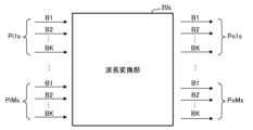
- FIG. 2 is an explanatory diagram showing input/output lines of a wavelength converter having a single band configuration according to the present embodiment.
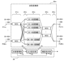
- FIG. 2 is a configuration diagram showing details of a single-band wavelength conversion section and a controller according to the present embodiment.
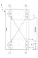
- FIG. 2 is a configuration diagram showing a WXC device with a multiband configuration according to the present embodiment.
- FIG. 2 is an explanatory diagram showing input/output lines of a wavelength converter having a multiband configuration according to the present embodiment.
- FIG. 2 is a configuration diagram showing details of a multiband wavelength conversion section and a controller according to the present embodiment.
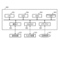
- FIG. 2 is a hardware configuration diagram of a controller according to the present embodiment.
- the WXC device microwave cross-connect device
- the WXC device has an input/output port for inputting and outputting optical signals of multiple wavelength bands (multiband), and the It has a WSS that performs wavelength selection and route switching on signals and transmits them from the output port.
- the difference between the two embodiments is the type of WSS used.
- the WXC device 100s shown in FIGS. 1 to 3 uses a WSS (single band configuration) capable of wavelength selection and route switching for one wavelength band (single band).
- the suffix "s" of each component in the WXC device 100s indicates a single band configuration.
- the WXC device 100m shown in FIGS. 4 to 6 uses a WSS (with a multiband configuration) that can select wavelengths and switch routes at once for multiple wavelength bands (multibands).
- the suffix "m" of each component within the WXC device 100m indicates a multiband configuration.
- the wavelength bands are, for example, three wavelength bands, in order from the shortest wavelength side: an S band from 1460 nm to 1530 nm, a C band from 1530 nm to 1565 nm, and an L band from 1565 nm to 1625 nm.
- FIG. 1 is a configuration diagram showing a WXC device 100s with a single band configuration.
- the WXC device 100s is connected to external devices via optical fibers through M input ports (ports Pi1, ..., ports PiM) and M output ports (ports Po1, ..., ports PoM). ing.
- Optical signals in a plurality of wavelength bands are transmitted and received through optical fibers connected to each input/output port of the WXC device 100s.
- the WXC device 100s includes a WXC section (wavelength cross connect section) 10s, a wavelength conversion section 20s, and a controller 30.
- the controller 30 controls the WXC section 10s and the wavelength conversion section 20s.
- the WXC unit 10s receives an optical signal in which optical signals in a plurality of wavelength bands are combined from each input port of the WXC device 100s, and wavelength-converts the received optical signal into individual wavelength bands. input into the section 20s.
- the WXC unit 10s then multiplexes the optical signals in individual wavelength bands output from the wavelength conversion unit 20s, and outputs the multiplexed optical signals from each output port of the WXC device 100s.
- the WXC section 10s switches the route of an optical signal that does not require wavelength conversion by itself, and transmits an optical signal that requires wavelength conversion to the wavelength conversion section 20s. Thereby, route switching can be performed without deterioration of transmission quality due to wavelength conversion.
- a configuration in which the wavelength conversion section 20s is separated as a separate component from the WXC section 10s is also called a trunk type.
- the WXC unit 10s is connected in order from the input port side (left side in FIG. 1) to a duplexer 11s, an inlet WSS 12s, an output WSS 13s, and a multiplexer 14s.
- the M duplexers 11s are connected to each M input port in a 1:1 ratio.
- Each demultiplexer 11s converts a multi-band optical signal inputted from each input port (an optical signal obtained by combining an S-band optical signal + a C-band optical signal + an L-band optical signal) into each single-band optical signal. (S-band optical signal, C-band optical signal, L-band optical signal). Then, each demultiplexer 11s outputs each demultiplexed optical signal to the subsequent input WSS 12s for each wavelength band.
- the first demultiplexer 11s that receives the first optical signal from the first input port Pi1 demultiplexes the first optical signal into three optical signals.
- the first demultiplexer 11s outputs the demultiplexed S-band optical signal to the S-band input WSS 12s, outputs the demultiplexed C-band optical signal to the C-band input WSS 12s, and demultiplexes the S-band optical signal.
- the waved L-band optical signal is output to the L-band input WSS 12s.
- the incoming WSS 12s is configured by wavelength band, such as an S-band WSS, a C-band WSS, and an L-band WSS, and receives an optical signal in the corresponding wavelength band from the demultiplexer 11s. That is, the incoming WSS 12s connected to the input port Pi1 is prepared so as to be able to switch directions in the wavelength band of the optical signal input from the input port Pi1. In the example of FIG. 1, one branching filter 11s and three inlet WSSs 12s are connected, so the total number of inlet WSSs 12s is (3 ⁇ M).
- the output WSS 13s is also configured by wavelength band, such as an S-band WSS, a C-band WSS, and an L-band WSS, and receives optical signals in the corresponding wavelength bands from the demultiplexer 11s. That is, since one incoming WSS 12s and one outgoing WSS 13s are connected, the total number of outgoing WSSs 13s is also (3 ⁇ M).
- the incoming WSS 12s and the outgoing WSS 13s which handle the same wavelength band, are directly connected to each other in order to transmit optical signals that do not require wavelength conversion.
- the S-band WSS of the ingress WSS 12s is connected to the S-band WSS of the egress WSS 13s, which is in the same S band and does not require wavelength conversion.
- the ingress WSS 12s inputs them to the input port provided in the WXC device 10s instead of inputting them to the wavelength converter 20s. Route switching is performed by the side WSS 12s.
- the input WSS 12s outputs optical signals from each output port of the WXC device 100s via the output WSS 13s.
- optical signals that do not require wavelength conversion can be transmitted without deteriorating transmission quality without passing through the wavelength conversion section 20s, and wavelength collision can be avoided.
- the incoming WSS 12s is also connected to the wavelength conversion section 20s.
- the optical signal that requires wavelength conversion is subjected to wavelength conversion by passing from the incoming WSS 12s to the wavelength conversion unit 20s, and wavelength collision can be avoided.
- the output side WSS 13s is also connected to the wavelength conversion section 20s. Thereby, the optical signal whose wavelength has been converted by the wavelength converter 20s is route-switched along with the optical signal that does not require wavelength conversion via the output WSS 13s.
- the M multiplexers 14s are connected in a 1:1 ratio to each of the M output ports.
- Each multiplexer 14s converts each single-band optical signal (S-band optical signal, C-band optical signal, L-band optical signal) input from each output WSS 13s into a multi-band optical signal (S-band optical signal).
- the optical signal is combined into an optical signal in which the optical signal + C band optical signal + L band optical signal are combined.
- Each multiplexer 14s outputs each multiplexed optical signal to an external device from the connected output port.
- FIG. 2 is an explanatory diagram showing input and output lines of the wavelength conversion section 20s with a single band configuration.
- the number of wavelength bands is three (S band, C band, and L band) to make the explanation easy to understand.
- the number of wavelength bands will be generalized to K (B1 band, B2 band, . . . BK band) for explanation.
- the wavelength conversion unit 20s converts the wavelength of the optical signal input from the WXC unit 10s to an arbitrary wavelength, and also switches the optical signal to an arbitrary output port according to the setting of the optical path.
- the wavelength conversion by the wavelength conversion unit 20s also includes wavelength band conversion (conversion to a wavelength in another wavelength band).
- the wavelength converter 20s converts the wavelength band-specific optical signals (B1, B2,..., BK) input from the input port Pi1 in FIG. Accepted from the incoming WSS12s.
- the wavelength converter 20s receives input of optical signals according to wavelength bands input from the input port PiM in FIG. Further, the wavelength converter 20s outputs the wavelength band-specific optical signals output from the output port Po1 in FIG.
- the wavelength converter 20s outputs the wavelength band-specific optical signals output from the output port PoM in FIG. 1 to the wavelength band-specific output WSS 13s connected to the output port PoM of the WXC unit 10s.
- FIG. 3 is a configuration diagram showing details of the wavelength conversion section 20s and the controller 30 having a single band configuration.
- the wavelength conversion unit 20s is configured by connecting an input side WSS 21s, an input multiplexer 22s, a converter 23s, an output WSS 24s, and an output multiplexer 25s in the order of input of the optical signal.
- the wavelength conversion unit 20s has input WSSs 21s that can receive optical signals in individual wavelength bands input from the WXC unit 10s for each wavelength band and each input port.
- the input WSS (input wavelength switch) 21s outputs the optical signal input from each input port of the WXC device 100s to one of the plurality of converters 23s.
- the incoming WSS 21s has one input terminal that receives the optical signal for each wavelength band input from the WXC unit 10s, and outputs the optical signal to the incoming multiplexer 22s that goes to the unused converter 23s. and one or more output terminals. Note that in FIG. 3, some of the connecting lines between the constituent elements are omitted because the drawing would become complicated if all the connecting lines were depicted.
- the input multiplexer 22s has one or more input terminals that receive optical signals according to wavelength bands input from the input WSS 21s, and outputs the result of multiplexing the received one or more optical signals to the converter 23s. It has one output terminal for Note that the wavelength band (for example, B1) of the optical signal that the input multiplexer 22s receives from the input terminal, and the wavelength band (for example, B1) before conversion of the converter 23s that receives the optical signal that the input multiplexer 22s outputs from the output terminal. For example, in the case of a "B1 ⁇ B2 converter", B1) is connected in a matching manner.
- the converter 23s converts the wavelength band of the optical signal input from each input WSS 21s that handles the optical signal input from each input port into another wavelength band, and outputs the converted optical signal to the output WSS 24s. . Therefore, the converter 23s has one input terminal that receives the optical signal input from the input multiplexer 22s, and outputs the result of converting the wavelength band of the received optical signal to another wavelength band to the output WSS 24s. It has one output terminal for. That is, the converter 23s is connected to the output side WSS 24s that can switch the route of the optical signal in the converted wavelength band.
- FIG. 3 as in "B1 ⁇ B2 converter", when each converter 23s performs wavelength conversion, the wavelength band before conversion (here, B1) and the wavelength band after conversion (here, B2) are shown. The combination with is described in the parts.
- the converter 23s receives an optical signal from the incoming WSS 21s connected to the input port Pi1 and an optical signal from the incoming WSS 21s connected to the input port PiM from the incoming multiplexer 22s, respectively.
- one converter 23s is shared by input ports Pi1 to PiM (M input ports).
- the output WSS (output wavelength switch) 24s routes the optical signal input from the converter 23s to each output port of the WXC device 100s. Therefore, the output WSS 24s has one input terminal for receiving the optical signal input from the converter 23s, and one or more output terminals for outputting the received optical signal to a route switching destination according to the optical path settings. has.
- the output multiplexer 25s has one or more input terminals that receive optical signals for each wavelength band input from the output WSS 24s, and outputs the results of multiplexing the one or more received optical signals for each wavelength band. It has one output terminal for outputting to the side WSS 13s.
- the number of converters 23s is arbitrary, and can be increased or decreased as appropriate depending on the usage status of the converters 23s. Furthermore, the same number of input multiplexers 22s, converters 23s, and output WSSs 24s are provided because they are connected 1:1 to each other. In addition, for the combination of "input wavelength band ⁇ output wavelength band" handled by the converter 23s, three “B1 ⁇ B2 converters” are prepared, four “B1 ⁇ B3 converters” are prepared, etc. Any number of items can be prepared for each combination.
- the number of ingress WSSs 21s is calculated by multiplying the number of input ports of the WXC device 100s (M in Figure 1) x the number of wavelength bands input from the input ports of the WXC device 100s (K in Figure 1). It is the number of products.
- the controller 30 manages whether the converter 23s is in use or unused, and controls the input WSS 21s to output an optical signal to the unused converter 23s. Therefore, the controller 30 includes a state management section 31, an output setting section 32, and an expansion instruction section 33, and manages the WXC section 10s and the wavelength conversion section 20s in the WXC device 100s.
- the controller 30 is connected to each converter 23s of the wavelength conversion section 20s, and the state management section 31 monitors the usage status (in use or unused state) of each converter 23s.
- the controller 30 is connected to each WSS within the WXC device 100s.
- Each WSS is an input WSS (second input wavelength switch) 12s and an output WSS 13s of the WXC section 10s, and an input WSS 21s and an output WSS 24s of the wavelength conversion section 20s.
- the output setting unit 32 determines which wavelength band optical signals are to be distributed to which output terminals (route switching) for the wavelength band optical signals input to each WSS, and which wavelengths are assigned to the output terminals. Set whether to allocate bands.
- the output setting unit 32 refers to the usage status of each converter 23s acquired by the state management unit 31, and when distributing the optical signal from the input side WSS 21s to the subsequent input side multiplexer 22s ⁇ converter 23s. , selects the incoming multiplexer 22s toward the unused converter 23s as the output destination. Thereby, collision of optical signals within the converter 23s can be avoided.
- the output setting section 32 outputs an output signal to the input side WSS 12s of the WXC section 10s so as not to transmit the optical signal from the WXC section 10s to the wavelength conversion section 20s. Set the destination to be the outgoing WSS 13s.
- the output setting unit 32 does not input the optical signals received from each input port of the WXC device 100s to the wavelength conversion unit 20s. Instead, the output setting unit 32 controls output from each output port of the WXC device 100s by switching the route using the input WSS 12s provided in the WXC unit 10s.
- the expansion instruction unit 33 acquires the usage status of each converter 23s from the status management unit 31, and determines the future status of the converter 23s based on the operating rate of the converter 23s calculated from the usage status of each converter 23s.
- the expansion instruction unit 33 creates a plan to add 50 converters 23s to a total of 150, and instructs the operator of the plan. This instruction may also include that, along with the addition of the converters 23s, the number of incoming multiplexers 22s and the number of outgoing WSSs 24s will be increased to 150 in total.
- the arranged converter 23s can be shared by all input ports. Therefore, compared to a configuration in which the converter 23s is prepared exclusively for one input port, there is greater flexibility in increasing or decreasing the number of converters 23s, and it is possible to proactively increase or decrease the number of converters 23s depending on the communication load.
- the WXC device 100s with a single band configuration a WSS corresponding to one wavelength band is used as each WSS in the device.
- the WXC device 100s that accommodates WSS which has a simple mechanism and is inexpensive, can be constructed at low cost.
- FIG. 4 is a configuration diagram showing a WXC device 100m with a multiband configuration.
- the WXC device 100m includes a WXC section 10m, a wavelength conversion section 20m, and a controller 30.
- the controller 30 controls the WXC section 10m and the wavelength conversion section 20m similarly to the first embodiment.
- the WXC device 100m Similar to the WXC device 100s with a single band configuration, the WXC device 100m has M input ports (ports Pi1, ..., ports PiM) and M input ports (ports Po1, ..., ports PoM). , each connected to an external device via optical fiber.
- Optical signals in a plurality of wavelength bands are transmitted and received through optical fibers connected to each input/output port of the WXC device 100m.
- the WXC unit 10m receives an optical signal in which optical signals in a plurality of wavelength bands are combined from each input port of the WXC device 100m, inputs the received optical signal to the wavelength conversion unit 20m, and inputs the received optical signal to the wavelength conversion unit 20m.
- the output optical signals are output from each output port of the WXC device 100m.
- the WXC unit 10m is connected to an inlet WSS 12m and an outlet WSS 13m in order from the input port side (left side in FIG. 4).
- the demultiplexer 11s and multiplexer 14s used in the single-band configuration become unnecessary, so the WXC section 10m can be made slim.
- the incoming WSS 12m can receive optical signals of each wavelength band (S band, C band, L band) from the same input port (for example, port Pi1). Since there is a 1:1 correspondence between the ingress WSS 12m and the input ports, the total number of ingress WSSs 12m is M.
- the input WSS 12m with a multi-band configuration has an output terminal that transmits optical signals that do not require wavelength conversion to the output WSS 13m in the subsequent stage, and an output terminal that transmits optical signals that require wavelength conversion. It has an output terminal for transmitting data to the section 20m.
- FIG. 5 is an explanatory diagram showing input and output lines of the wavelength conversion section 20m having a multiband configuration.
- the number of wavelength bands is K (B1 band, B2 band, . . . BK band).
- the wavelength converter 20m with a multi-band configuration converts the wavelength of the optical signal input from the WXC unit 10m to an arbitrary wavelength, and also converts the wavelength of the optical signal input from the WXC unit 10m to an arbitrary output according to the settings of the optical path. Switch route to port.
- the single band configuration of FIG. 2 the input/output terminals of the wavelength converter 20s are separated by wavelength band, whereas in the multiband configuration of FIG. Each port is separate, and signals in multiple wavelength bands can be transmitted through one port.
- FIG. 6 is a configuration diagram showing details of the wavelength conversion section 20m and the controller 30 having a multiband configuration.
- the controller 30 with the multi-band configuration includes a state management section 31, an output setting section 32, and an expansion instruction section 33, as in the case of the single-band configuration.
- the state management unit 31 monitors the usage status (in use or unused state) of each converter 23m.
- the output setting unit 32 refers to the usage status of each converter 23m acquired by the state management unit 31, and selects unused or The incoming multiplexer 22m heading towards the state converter 23m is selected as the output destination.
- the expansion instruction unit 33 obtains the usage status of each converter 23m from the status management unit 31, and determines the future expansion of the converter 23m based on the operating rate of the converter 23m calculated from the usage status of each converter 23m. Or draw up a plan for reduction of facilities and instruct the operator on the plan.
- Differences (1) to (5) between the single band configuration in FIG. 3 and the multiband configuration in FIG. 6 are listed below.
- (1) Differences in the input side WSS 21m Due to the decrease in the number of input terminals of the wavelength conversion section 20m from (number of input ports) x (number of wavelength bands) in Figure 2 to (number of input ports) in Figure 5. , the number of incoming WSSs 21m is also reduced to the same number as the number of input ports (M). That is, the wavelength converter 20m includes an input WSS 21m for each input port, which can input optical signals in a plurality of wavelength bands input from the WXC unit 10m.
- the ingress WSS 21s in FIG. 3 is a low-performance WSS that supports a single band
- the ingress WSS 21m in FIG. 6 requires a high-performance WSS that supports multi-bands.
- the number of input multiplexers 22m is the same as the number of converters 23m connected 1:1 in both the single band configuration in Figure 3 and the multiband configuration in Figure 6. be. Note that since the inlet WSS 21m in FIG. 6 is reduced, the wiring between the inlet WSS 21m and the inlet multiplexer 22m becomes simpler.
- the output WSS 24s in Figure 3 is a low-function WSS that supports single band, but the output WSS 24m in Figure 6 requires a high-performance WSS that supports multi-band. .
- the output WSS 24m supports multiband, and by connecting multiple converters 23m and one output WSS 24m within a range where the wavelength bands after conversion do not overlap (n:1 connection), the output WSS 24m Reduce the number of pieces.
- the WXC section 10m and the wavelength conversion section 20m use high-performance WSSs that support multi-bands, thereby reducing the number of WSSs, building a 100m WXC device in a small space, and saving power. Can be operated.
- FIG. 7 is a hardware configuration diagram of the controller 30.
- the controller 30 is configured as a computer 900 having a CPU 901, a RAM 902, a ROM 903, an HDD 904, a communication I/F 905, an input/output I/F 906, and a media I/F 907.
- Communication I/F 905 is connected to external communication device 915.
- the input/output I/F 906 is connected to the input/output device 916.
- the media I/F 907 reads and writes data from the recording medium 917.
- the CPU 901 controls each unit by executing a program (also called an application or an abbreviated application) read into the RAM 902 .
- a program also called an application or an abbreviated application
- This program can also be distributed via a communication line or recorded on a recording medium 917 such as a CD-ROM.
- the controller 30 may be implemented using an FPGA (Field Programmable Gate Array) or an ASIC (application specific integrated circuit) that implements program logic.
- the controller 30 may be configured as a separate casing from the WXC devices 100s and 100m, and one controller 30 may manage multiple WXC devices 100s and 100m.
- the present invention is a WXC device 100s having a wavelength conversion section 20s and a controller 30,
- the wavelength conversion section 20s is an input WSS 21s that outputs optical signals input from each input port of the WXC device 100s to any of the plurality of converters 23s; a converter 23s that converts the wavelength band of the optical signal input from each input WSS 21s that handles the optical signal input from each input port into another wavelength band, and outputs the converted optical signal to the output WSS 24s; It has an output side WSS 24s that switches the optical signal input from the converter 23s to each output port of the WXC device 100s,
- the controller 30 manages the status of each converter 23s as being in use or unused, and controls the input WSS 21s to output an optical signal to the unused converter 23s.
- converters 23s can be flexibly added or removed according to demand. be able to. Further, the converter 23s is not provided for each input port, but is shared by a plurality of input ports. Furthermore, by controlling the incoming WSS 21s to output an optical signal to the unused converter 23s, the operating rate of the converter 23s can be improved and the number of wavelength converters 20s can be reduced. In this way, by reducing the number of wavelength converters 20s to a necessary number, the cost of the WXC device 100s can be reduced. In this way, the present invention has proposed a configuration of a WXC device that can appropriately set the number of converters included in the WXC device.
- the WXC device 100s further includes a WXC section 10s,
- the WXC unit 10s receives an optical signal in which optical signals in a plurality of wavelength bands are combined from each input port of the WXC device 100s, and wavelength-converts the optical signal obtained by demultiplexing the received optical signal into individual wavelength bands.
- unit 20s and output from the wavelength conversion unit 20s, which are individual wavelength bands, are combined, and the combined optical signals are output from each output port of the WXC device 100s,
- the wavelength conversion section 20s is characterized in that it is provided with input side WSSs 21s for each wavelength band and each input port, into which optical signals in individual wavelength bands inputted from the WXC section 10s can be input.
- the cost of the WXC device 100s can be reduced by using the low-cost input side WSS 21s that supports a single band in the wavelength conversion section 20s.
- the WXC device 100m further includes a WXC section 10m,
- the WXC unit 10m receives an optical signal in which optical signals in a plurality of wavelength bands are combined from each input port of the WXC device 100m, inputs the received optical signal to the wavelength conversion unit 20m, and inputs the received optical signal to the wavelength conversion unit 20m.
- the wavelength conversion unit 20m is characterized in that each input port is provided with an input WSS 21m capable of inputting optical signals in a plurality of wavelength bands input from the WXC unit 10m.
- the number of ingress WSSs 21m and wiring layout can be simplified, and the size of the WXC device 100m can be reduced.
- optical signals that do not require wavelength band conversion are input into the WXC unit 10s instead of being input to the wavelength conversion unit 20s.
- the feature is that by switching the route using the incoming WSS 12s provided in the WXC device 100s, output is made from each output port of the WXC device 100s.
- optical signals that do not require wavelength band conversion can be transmitted at high speed by bypassing the wavelength conversion section 20s.
- the controller 30 when the converter 23s in an unused state does not exist, the controller 30 is provided in the WXC unit 10s, instead of inputting the optical signal received from each input port of the WXC device 100s to the wavelength conversion unit 20s.
- the feature is that the input side WSS 12s performs route switching to control output from each output port of the WXC device 100s.
- the wavelength conversion section 20s can be bypassed to process the optical signal without loss.
Landscapes
- Engineering & Computer Science (AREA)
- Computer Networks & Wireless Communication (AREA)
- Signal Processing (AREA)
- Physics & Mathematics (AREA)
- Electromagnetism (AREA)
- Computing Systems (AREA)
- Optical Communication System (AREA)
- Use Of Switch Circuits For Exchanges And Methods Of Control Of Multiplex Exchanges (AREA)
Priority Applications (4)
| Application Number | Priority Date | Filing Date | Title |
|---|---|---|---|
| PCT/JP2022/017572 WO2023199397A1 (ja) | 2022-04-12 | 2022-04-12 | 波長クロスコネクト装置、および、波長クロスコネクト方法 |
| JP2024515207A JP7786567B2 (ja) | 2022-04-12 | 2022-04-12 | 波長クロスコネクト装置、および、波長クロスコネクト方法 |
| US18/854,619 US20250330257A1 (en) | 2022-04-12 | 2022-04-12 | Wavelength cross connect device and wavelength cross connect method |
| JP2025210080A JP7907758B2 (ja) | 2025-12-01 | 光伝送システム、光伝送方法、および、波長クロスコネクト装置 |
Applications Claiming Priority (1)
| Application Number | Priority Date | Filing Date | Title |
|---|---|---|---|
| PCT/JP2022/017572 WO2023199397A1 (ja) | 2022-04-12 | 2022-04-12 | 波長クロスコネクト装置、および、波長クロスコネクト方法 |
Publications (1)
| Publication Number | Publication Date |
|---|---|
| WO2023199397A1 true WO2023199397A1 (ja) | 2023-10-19 |
Family
ID=88329261
Family Applications (1)
| Application Number | Title | Priority Date | Filing Date |
|---|---|---|---|
| PCT/JP2022/017572 Ceased WO2023199397A1 (ja) | 2022-04-12 | 2022-04-12 | 波長クロスコネクト装置、および、波長クロスコネクト方法 |
Country Status (3)
| Country | Link |
|---|---|
| US (1) | US20250330257A1 (cg-RX-API-DMAC7.html) |
| JP (1) | JP7786567B2 (cg-RX-API-DMAC7.html) |
| WO (1) | WO2023199397A1 (cg-RX-API-DMAC7.html) |
Cited By (1)
| Publication number | Priority date | Publication date | Assignee | Title |
|---|---|---|---|---|
| WO2026099930A1 (ja) * | 2024-11-05 | 2026-05-15 | Ntt株式会社 | 波長変換装置 |
Citations (4)
| Publication number | Priority date | Publication date | Assignee | Title |
|---|---|---|---|---|
| JP2000134649A (ja) * | 1998-10-21 | 2000-05-12 | Toshiba Corp | 光クロスコネクト装置 |
| JP2000171841A (ja) * | 1998-12-09 | 2000-06-23 | Nippon Telegr & Teleph Corp <Ntt> | 光パスクロスコネクトスイッチ |
| WO2022009291A1 (ja) * | 2020-07-06 | 2022-01-13 | 日本電信電話株式会社 | 波長クロスコネクト装置及び波長クロスコネクト方法 |
| WO2022009292A1 (ja) * | 2020-07-06 | 2022-01-13 | 日本電信電話株式会社 | 波長クロスコネクト装置、マルチバンド伝送システム及びマルチバンド伝送方法 |
-
2022
- 2022-04-12 WO PCT/JP2022/017572 patent/WO2023199397A1/ja not_active Ceased
- 2022-04-12 US US18/854,619 patent/US20250330257A1/en active Pending
- 2022-04-12 JP JP2024515207A patent/JP7786567B2/ja active Active
Patent Citations (4)
| Publication number | Priority date | Publication date | Assignee | Title |
|---|---|---|---|---|
| JP2000134649A (ja) * | 1998-10-21 | 2000-05-12 | Toshiba Corp | 光クロスコネクト装置 |
| JP2000171841A (ja) * | 1998-12-09 | 2000-06-23 | Nippon Telegr & Teleph Corp <Ntt> | 光パスクロスコネクトスイッチ |
| WO2022009291A1 (ja) * | 2020-07-06 | 2022-01-13 | 日本電信電話株式会社 | 波長クロスコネクト装置及び波長クロスコネクト方法 |
| WO2022009292A1 (ja) * | 2020-07-06 | 2022-01-13 | 日本電信電話株式会社 | 波長クロスコネクト装置、マルチバンド伝送システム及びマルチバンド伝送方法 |
Non-Patent Citations (1)
| Title |
|---|
| NAKAGAWA MASAHIRO; KAWAHARA HIROKI; SEKI TAKESHI; MIYAMURA TAKASHI: "Adaptive Link-by-Link Band Allocation: A Novel Adaptation Scheme in Multi-Band Optical Networks", 2021 INTERNATIONAL CONFERENCE ON OPTICAL NETWORK DESIGN AND MODELING (ONDM), IFIP TC6 WG6.10, 28 June 2021 (2021-06-28), pages 1 - 6, XP033948512, DOI: 10.23919/ONDM51796.2021.9492502 * |
Cited By (1)
| Publication number | Priority date | Publication date | Assignee | Title |
|---|---|---|---|---|
| WO2026099930A1 (ja) * | 2024-11-05 | 2026-05-15 | Ntt株式会社 | 波長変換装置 |
Also Published As
| Publication number | Publication date |
|---|---|
| JPWO2023199397A1 (cg-RX-API-DMAC7.html) | 2023-10-19 |
| JP7786567B2 (ja) | 2025-12-16 |
| US20250330257A1 (en) | 2025-10-23 |
| JP2026032223A (ja) | 2026-02-25 |
Similar Documents
| Publication | Publication Date | Title |
|---|---|---|
| EP3176968B1 (en) | Optical communication device, optical communication system, and optical communication method | |
| JP5063558B2 (ja) | 光中継装置 | |
| JP2012015726A (ja) | 光分岐挿入装置 | |
| US11870552B2 (en) | Apparatus and method for coherent optical multiplexing 1+1 protection | |
| JP2020137042A (ja) | 伝送装置及び伝送システム | |
| JP7609272B2 (ja) | 波長クロスコネクト装置及び波長クロスコネクト方法 | |
| JP7472982B2 (ja) | 波長クロスコネクト装置、マルチバンド伝送システム及びマルチバンド伝送方法 | |
| JP7671006B2 (ja) | 光ゲートウェイ装置 | |
| US9609401B2 (en) | Optical switch, optical transmission device, and optical switching method | |
| JP2005065019A (ja) | 波長分割多重伝送システム | |
| US11722235B2 (en) | Optical branch insertion device and optical branch insertion method | |
| JP7694655B2 (ja) | 波長クロスコネクト装置及び波長クロスコネクト方法 | |
| JP7786567B2 (ja) | 波長クロスコネクト装置、および、波長クロスコネクト方法 | |
| US6859576B2 (en) | Optical cross-connect system | |
| JP7687395B2 (ja) | 波長クロスコネクト装置及び波長クロスコネクト方法 | |
| US7356217B2 (en) | Add-drop device and cross-connect device for wavelength multiplex signals | |
| US12432004B2 (en) | ROADM architecture for wide spectrum channels | |
| JP5023021B2 (ja) | 光分岐挿入多重化装置、及び光レベル調整方法 | |
| JP5340368B2 (ja) | 光中継装置 | |
| WO2022259321A1 (ja) | 波長クロスコネクト装置及び波長クロスコネクト方法 | |
| JP5340369B2 (ja) | 光中継装置 | |
| JP4387234B2 (ja) | 光分岐挿入装置及び光分岐挿入装置体 | |
| US20260019185A1 (en) | ROADM Architecture for Wide Spectrum Channels | |
| JP2008259132A (ja) | 光クロスコネクトシステム及び光クロスコネクトシステムにおける信号制御方法 | |
| JP7701479B2 (ja) | 可変粒度光ルーティングを伴うネットワークアーキテクチャ |
Legal Events
| Date | Code | Title | Description |
|---|---|---|---|
| 121 | Ep: the epo has been informed by wipo that ep was designated in this application |
Ref document number: 22937377 Country of ref document: EP Kind code of ref document: A1 |
|
| ENP | Entry into the national phase |
Ref document number: 2024515207 Country of ref document: JP Kind code of ref document: A |
|
| WWE | Wipo information: entry into national phase |
Ref document number: 18854619 Country of ref document: US |
|
| NENP | Non-entry into the national phase |
Ref country code: DE |
|
| 122 | Ep: pct application non-entry in european phase |
Ref document number: 22937377 Country of ref document: EP Kind code of ref document: A1 |
|
| WWP | Wipo information: published in national office |
Ref document number: 18854619 Country of ref document: US |