WO2023195437A1 - 給電制御装置、給電制御方法及びコンピュータプログラム - Google Patents
給電制御装置、給電制御方法及びコンピュータプログラム Download PDFInfo
- Publication number
- WO2023195437A1 WO2023195437A1 PCT/JP2023/013762 JP2023013762W WO2023195437A1 WO 2023195437 A1 WO2023195437 A1 WO 2023195437A1 JP 2023013762 W JP2023013762 W JP 2023013762W WO 2023195437 A1 WO2023195437 A1 WO 2023195437A1
- Authority
- WO
- WIPO (PCT)
- Prior art keywords
- relay contact
- power supply
- voltage value
- value
- abnormality
- Prior art date
- Legal status (The legal status is an assumption and is not a legal conclusion. Google has not performed a legal analysis and makes no representation as to the accuracy of the status listed.)
- Ceased
Links
Images





Classifications
-
- G—PHYSICS
- G01—MEASURING; TESTING
- G01R—MEASURING ELECTRIC VARIABLES; MEASURING MAGNETIC VARIABLES
- G01R31/00—Arrangements for testing electric properties; Arrangements for locating electric faults; Arrangements for electrical testing characterised by what is being tested not provided for elsewhere
- G01R31/327—Testing of circuit interrupters, switches or circuit-breakers
- G01R31/3277—Testing of circuit interrupters, switches or circuit-breakers of low voltage devices, e.g. domestic or industrial devices, such as motor protections, relays, rotation switches
- G01R31/3278—Testing of circuit interrupters, switches or circuit-breakers of low voltage devices, e.g. domestic or industrial devices, such as motor protections, relays, rotation switches of relays, solenoids or reed switches
-
- B—PERFORMING OPERATIONS; TRANSPORTING
- B60—VEHICLES IN GENERAL
- B60R—VEHICLES, VEHICLE FITTINGS, OR VEHICLE PARTS, NOT OTHERWISE PROVIDED FOR
- B60R16/00—Electric or fluid circuits specially adapted for vehicles and not otherwise provided for; Arrangement of elements of electric or fluid circuits specially adapted for vehicles and not otherwise provided for
- B60R16/02—Electric or fluid circuits specially adapted for vehicles and not otherwise provided for; Arrangement of elements of electric or fluid circuits specially adapted for vehicles and not otherwise provided for electric constitutive elements
-
- G—PHYSICS
- G01—MEASURING; TESTING
- G01R—MEASURING ELECTRIC VARIABLES; MEASURING MAGNETIC VARIABLES
- G01R19/00—Arrangements for measuring currents or voltages or for indicating presence or sign thereof
- G01R19/165—Indicating that current or voltage is either above or below a predetermined value or within or outside a predetermined range of values
- G01R19/16566—Circuits and arrangements for comparing voltage or current with one or several thresholds and for indicating the result not covered by subgroups G01R19/16504, G01R19/16528, G01R19/16533
- G01R19/1659—Circuits and arrangements for comparing voltage or current with one or several thresholds and for indicating the result not covered by subgroups G01R19/16504, G01R19/16528, G01R19/16533 to indicate that the value is within or outside a predetermined range of values (window)
-
- G—PHYSICS
- G01—MEASURING; TESTING
- G01R—MEASURING ELECTRIC VARIABLES; MEASURING MAGNETIC VARIABLES
- G01R31/00—Arrangements for testing electric properties; Arrangements for locating electric faults; Arrangements for electrical testing characterised by what is being tested not provided for elsewhere
-
- G—PHYSICS
- G01—MEASURING; TESTING
- G01R—MEASURING ELECTRIC VARIABLES; MEASURING MAGNETIC VARIABLES
- G01R31/00—Arrangements for testing electric properties; Arrangements for locating electric faults; Arrangements for electrical testing characterised by what is being tested not provided for elsewhere
- G01R31/50—Testing of electric apparatus, lines, cables or components for short-circuits, continuity, leakage current or incorrect line connections
- G01R31/56—Testing of electric apparatus
-
- H—ELECTRICITY
- H01—ELECTRIC ELEMENTS
- H01H—ELECTRIC SWITCHES; RELAYS; SELECTORS; EMERGENCY PROTECTIVE DEVICES
- H01H47/00—Circuit arrangements not adapted to a particular application of the relay and designed to obtain desired operating characteristics or to provide energising current
-
- H—ELECTRICITY
- H01—ELECTRIC ELEMENTS
- H01H—ELECTRIC SWITCHES; RELAYS; SELECTORS; EMERGENCY PROTECTIVE DEVICES
- H01H47/00—Circuit arrangements not adapted to a particular application of the relay and designed to obtain desired operating characteristics or to provide energising current
- H01H47/002—Monitoring or fail-safe circuits
Definitions
- the present disclosure relates to a power supply control device, a power supply control method, and a computer program.
- This application claims priority based on Japanese Application No. 2022-062539 filed on April 4, 2022, and incorporates all the contents described in the said Japanese application.
- Patent Document 1 discloses a configuration for controlling power supply from a DC power source to a load.
- a relay contact is connected between the positive pole of the DC power source and one end of the load.
- the negative pole of the DC power supply and the other end of the load are grounded.
- a power supply control device is a power supply control device that controls power supply via a relay contact, and includes a processing unit that executes processing, and the processing unit is configured to perform processing when the relay contact is on. First, a first voltage value at one downstream end of the relay contact is acquired, and based on the acquired first voltage value, it is determined whether or not an abnormality has occurred in the relay contact.
- a power supply control method is a power supply control method for controlling power supply via a relay contact, wherein when the relay contact is on, a first A computer executes a step of acquiring a voltage value and a step of determining whether an abnormality has occurred in the relay contact based on the acquired first voltage value.
- a computer program includes the steps of: acquiring a first voltage value at one end of the downstream side of the relay contact when the relay contact through which current flows is on; and based on the acquired first voltage value. and causing the computer to execute the step of determining whether or not an abnormality has occurred in the relay contact.
- the present disclosure can be realized not only as a power supply control device including such a characteristic processing unit, but also as a power supply control method having such characteristic processing as steps, or such steps can be implemented in a computer. It can be realized as a computer program for execution. Furthermore, the present disclosure can be implemented as a semiconductor integrated circuit that implements part or all of a power supply control device, or as a power supply system that includes a power supply control device.
- FIG. 1 is a block diagram showing a main part configuration of a power supply system in Embodiment 1.
- FIG. FIG. 2 is a block diagram showing the configuration of main parts of a microcomputer. It is a chart showing the contents of a threshold number of times table and a number of times change table.
- 7 is a flowchart showing the procedure of switching processing. It is a flowchart which shows the procedure of abnormality detection processing. It is a flowchart which shows the procedure of abnormality detection processing. 5 is a timing chart showing an example of the operation of a microcomputer. 7 is a flowchart showing the procedure of abnormality detection processing in Embodiment 2.
- the present disclosure has been made in view of such circumstances, and its purpose is to provide a power supply control device, a power supply control method, and a computer program that can detect abnormalities in relay contacts.
- an abnormality in the relay contact can be detected.
- a power supply control device is a power supply control device that controls power supply via a relay contact, and includes a processing unit that executes processing, and the processing unit is configured to turn on the relay contact. If so, a first voltage value at one downstream end of the relay contact is acquired, and based on the acquired first voltage value, it is determined whether or not an abnormality has occurred in the relay contact.
- the processing unit repeatedly acquires the first voltage value during a predetermined period when the relay contact is on, and Each time it is obtained, it is determined whether the obtained first voltage value is a value outside the predetermined range, and if it is determined that the first voltage value is a value outside the predetermined range, the upper limit value of the predetermined range is determined. and a value close to the first voltage value among the lower limit values and the first voltage value, and if the cumulative value of the difference values calculated during the predetermined period is equal to or higher than the cumulative threshold value, It is determined that the abnormality has occurred at the relay contact.
- the processing unit repeatedly acquires the first voltage value during a predetermined period when the relay contact is on, and acquires the first voltage value during the predetermined period. If the number of first voltage values outside the predetermined range included in the plurality of first voltage values exceeds a predetermined number, it is determined that the abnormality has occurred in the relay contact.
- the processing unit acquires a second voltage value at one end of the upstream side of the relay contact, and when the relay contact is on, the When the second voltage value is greater than or equal to a predetermined voltage value, the first voltage value is acquired.
- the processing unit determines whether the number of times the relay contact is switched on or off is equal to or more than a threshold number of times, and The threshold number of times is decreased in accordance with the number of abnormality detections at which it is determined that the abnormality has occurred.
- the relay contact is arranged on a power supply path from the DC power source to the load.
- a power supply control method is a power supply control method for controlling power supply via a relay contact, wherein when the relay contact is on, one end of the downstream side of the relay contact A computer executes the steps of acquiring a first voltage value of , and determining whether or not an abnormality has occurred in the relay contact based on the acquired first voltage value.
- a computer program includes, when a relay contact through which current flows is on, acquiring a first voltage value at one downstream end of the relay contact; and the acquired first voltage.
- the computer is caused to execute the step of determining whether or not an abnormality has occurred in the relay contact based on the value.
- a first voltage value is acquired when the relay contact is on, and an abnormality in the relay contact is determined based on the acquired first voltage value. Detect.
- a plurality of first voltage values are acquired during a predetermined period. If the plurality of acquired first voltage values includes a first voltage value outside the predetermined range, the difference value (absolute value) between the first voltage value outside the predetermined range and the upper limit or lower limit of the predetermined range. Calculate. If the cumulative value of the difference values is greater than or equal to the cumulative threshold value, an abnormality in the relay contact is detected.
- a plurality of first voltage values are acquired during a predetermined period. If the number of first voltage values outside the predetermined range included in the plurality of acquired first voltage values exceeds a predetermined number, an abnormality in the relay contact is detected.
- the power supply control device if the second voltage value is low, an erroneous determination may be made, so the first voltage value is not acquired.
- the power supply control device it is determined whether the number of times the relay contact is switched is equal to or greater than the threshold number of times. This allows notification of relay contact replacement.
- the threshold number of times is lowered according to the number of times of abnormality detection. This speeds up the timing of notification of relay contact replacement.
- power supply from the DC power supply to the load is controlled by switching the relay contact on or off.
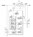
- FIG. 1 is a block diagram showing the main configuration of a power supply system 1 according to the first embodiment.
- a power supply system 1 is mounted on a vehicle C.
- the power supply system 1 includes a DC power supply 10, a power supply control device 11, a starter 12, and a load 13.
- the DC power supply 10 is, for example, a battery.
- the load 13 is, for example, an ECU (Electronic Control Unit).
- the power supply control device 11 has a relay 20.
- Relay 20 has relay contacts 30 and coil 31.
- the relay contact 30 has a COM terminal 30a, an NO terminal 30b, and a rod-shaped conductor 30c.
- the end of the conductor 30c is connected to the COM terminal 30a.
- the conductor 30c can rotate with the COM terminal 30a as a base point.
- the conductor 30c is pulled by a spring (not shown).
- a spring not shown
- the conductor 30c is separated from the NO terminal 30b by the spring.
- no current flows through the COM terminal 30a and the NO terminal 30b.
- Relay contact 30 is off.
- the coil 31 acts as a magnet and draws the conductor 30c toward the NO terminal 30b.
- the conductor 30c comes into contact with the NO terminal 30b.
- current can flow through the COM terminal 30a and the NO terminal 30b.
- Relay contact 30 is on.
- the negative electrode of the DC power supply 10 is grounded. Grounding is achieved, for example, by a connection to the body of the vehicle C.
- a positive electrode of the DC power supply 10 is connected to a COM terminal 30a of the relay contact 30 and one end of the starter 12.
- NO terminal 30b of relay contact 30 is connected to one end of load 13.
- the other end of the load 13 is grounded.
- the other end of the starter 12 is grounded.
- the power supply control device 11 switches the relay contact 30 from off to on. As a result, current flows from the positive electrode of the DC power source 10 to the relay contact 30, the load 13, and the negative electrode of the DC power source 10 in this order, as shown by the arrow. As a result, power is supplied to the load 13.
- the power supply control device 11 switches the relay contact 30 from on to off. As a result, the current flow through the relay contact 30 is stopped, and the power supply to the load 13 is stopped. As described above, the power supply control device 11 controls the power supply from the DC power supply 10 to the load 13 by switching the relay contact 30 on or off.
- the relay contact 30 When the relay contact 30 is on, current flows through the relay contact 30 in the order of the COM terminal 30a, the conductor 30c, and the NO terminal 30b.
- the COM terminal 30a corresponds to one end of the relay contact 30 on the upstream side.
- NO terminal 30b corresponds to one end of the relay contact 30 on the downstream side.
- the current flows from the positive electrode of the DC power supply 10 to the relay contact 30 and the load 13 in this order, so the relay contact 30 is arranged in the power supply path from the DC power supply 10 to the load 13.
- the positive electrode of the DC power supply 10 is further connected to one end of one or more on-vehicle devices. The other end of one or more on-vehicle devices is grounded.
- the DC power supply 10 supplies power to the starter 12 and one or more on-vehicle devices.
- the starter 12 is a motor for starting the engine of the vehicle C.
- current flows from the power supply main body through an internal resistance. The width of the voltage drop caused by the internal resistance increases as the current value of the current flowing through the internal resistance increases.
- the voltage value of the positive electrode of the DC power supply 10 is referred to as a power supply voltage value.
- the reference potential of the power supply voltage value is the ground potential. Since the positive electrode of the DC power supply 10 is connected to the COM terminal 30a of the relay contact 30, the power supply voltage value is the voltage value of the COM terminal 30a and corresponds to the second voltage value.
- the power supply voltage value is the voltage value at the output end of the internal resistor from which current is output.
- the power supply voltage value is lower as the current value of the current flowing through the internal resistance is larger.
- the starter 12 is activated, the current value flowing through the internal resistance is large. Therefore, when the starter 12 is activated, the power supply voltage value decreases significantly.
- the power supply voltage value returns to the value it had before the starter 12 started operating.
- the current value of the current flowing through the internal resistance does not change significantly due to the operation of one or more on-vehicle devices. Therefore, the power supply voltage value is stable regardless of whether one or more on-vehicle devices are operating.
- the power supply control device 11 includes a power supply voltage detection circuit 21, an output voltage detection circuit 22, a transistor 23, and a microcomputer (hereinafter referred to as a microcomputer) 24.
- the power supply voltage detection circuit 21 has voltage dividing resistors 21a and 21b.
- the output voltage detection circuit 22 has voltage dividing resistors 22a and 22b.
- the transistor 23 is an NPN type bipolar transistor.
- One end of the voltage dividing resistor 21a of the power supply voltage detection circuit 21 is connected to the COM terminal 30a of the relay contact 30.
- the other end of the voltage dividing resistor 21a is connected to one end of the voltage dividing resistor 21b.
- the other end of the voltage dividing resistor 21b is grounded.
- a connection node between the two voltage dividing resistors 21a and 21b is connected to the microcomputer 24.
- the two voltage dividing resistors 21a and 21b divide the voltage output from the positive electrode of the DC power supply 10.
- the voltage value of the voltage output from the positive electrode of the DC power supply 10 is the power supply voltage value.
- the power supply voltage detection circuit 21 outputs the voltage value of the divided voltage obtained by dividing the voltage by the two voltage dividing resistors 21a and 21b to the microcomputer 24 as analog power supply voltage information indicating the power supply voltage value.
- the power supply voltage information is a value obtained by dividing the power supply voltage value by a constant value, and is proportional to the power supply voltage value.
- One end of the voltage dividing resistor 22a of the output voltage detection circuit 22 is connected to the NO terminal 30b of the relay contact 30.
- the other end of the voltage dividing resistor 22a is connected to one end of the voltage dividing resistor 22b.
- the other end of the voltage dividing resistor 22b is grounded.
- a connection node between the two voltage dividing resistors 22a and 22b is connected to the microcomputer 24.
- the voltage value of the NO terminal 30b will be referred to as an output voltage value.
- the output voltage value is a voltage value whose reference potential is ground potential.
- the output voltage value corresponds to the first voltage value.
- the two voltage dividing resistors 22a and 22b divide the voltage at the NO terminal 30b.
- the output voltage detection circuit 22 outputs the voltage value of the divided voltage obtained by dividing the voltage by the two voltage dividing resistors 22a and 22b to the microcomputer 24 as analog output voltage information indicating the output voltage value.
- the output voltage information is a value obtained by dividing the output voltage value by a constant value, and is proportional to the output voltage value.
- one end of the coil 31 is connected to the COM terminal 30a.
- the other end of the coil 31 is connected to the collector of the transistor 23.
- the emitter of transistor 23 is grounded.
- the base of the transistor 23 is connected to the microcomputer 24.
- Transistor 23 functions as a switch.
- the microcomputer 24 switches the transistor 23 on or off by adjusting the voltage value of the base with respect to the ground potential. When transistor 23 is on, current is allowed to flow in the order of collector and emitter. When transistor 23 is off, no current flows through the collector and emitter.
- relay contact 30 When the transistor 23 is off, no current flows through the coil 31. Therefore, relay contact 30 is off.
- the microcomputer 24 switches the transistor 23 from off to on, current flows from the positive electrode of the DC power source 10 to the coil 31, the transistor 23, and the negative electrode of the DC power source 10 in this order. As current flows through coil 31, relay contact 30 switches from off to on.
- the microcomputer 24 switches the transistor 23 from on to off, current flow through the coil 31 is stopped. Therefore, relay contact 30 is switched off. As described above, the microcomputer 24 switches the relay contact 30 on or off by switching the transistor 23 on or off.
- FIG. 2 is a block diagram showing the main part configuration of the microcomputer 24.
- the microcomputer 24 includes a switching section 40, A/D conversion sections 41 and 42, a timer 43, a notification section 44, a storage section 45, and a control section 46. These are connected to an internal bus 47.
- the switching unit 40 is further connected to the base of the transistor 23.
- the A/D converter 41 is further connected to a connection node between the two voltage dividing resistors 21a and 21b.
- the A/D converter 42 is further connected to a connection node between the two voltage dividing resistors 22a and 22b.
- the switching unit 40 switches the transistor 23 on or off by adjusting the base voltage of the transistor 23 with the ground potential as a reference potential.
- the control unit 46 instructs the switching unit 40 to switch the transistor 23 on or off.
- Analog power supply voltage information is input from the power supply voltage detection circuit 21 to the A/D converter 41.
- the A/D converter 41 converts analog power supply voltage information input from the power supply voltage detection circuit 21 into digital power supply voltage information.
- the power supply voltage information converted by the A/D converter 41 is acquired by the controller 46.
- the power supply voltage value indicated by the power supply voltage information acquired by the control unit 46 substantially matches the power supply voltage value at the time of acquisition.
- Analog output voltage information is input from the output voltage detection circuit 22 to the A/D conversion section 42.
- the A/D converter 42 converts analog output voltage information input from the output voltage detection circuit 22 into digital output voltage information.
- the output voltage information converted by the A/D converter 42 is acquired by the controller 46.
- the output voltage value indicated by the output voltage information acquired by the control unit 46 substantially matches the output voltage value at the time of acquisition.
- the timer 43 starts and ends timing according to instructions from the control unit 46.
- the time measured by the timer 43 is read out by the control unit 46.
- the notification unit 44 performs notification according to instructions from the control unit 46. Specifically, the notification unit 44 notifies the replacement of the relay 20 by lighting a lamp or displaying a message. Note that the notification unit 44 may perform the notification by transmitting data indicating that the relay 20 has been replaced.
- the storage unit 45 is composed of, for example, volatile memory and nonvolatile memory.
- a computer program P is stored in the storage unit 45.
- the control unit 46 includes a processing element, such as a CPU (Central Processing Unit), that executes processing.
- the control unit 46 functions as a processing unit.
- the control unit 46 executes a switching process, an abnormality detection process, etc. in parallel by executing the computer program P.
- the switching process is a process of switching the relay contact 30 on or off.
- the control unit 46 determines whether the number of times the relay contact 30 is switched on or off is equal to or greater than a threshold number of times.
- the control unit 46 causes the notification unit 44 to perform notification when the number of times of switching is equal to or greater than the threshold number of times.
- the abnormality detection process is a process for detecting an abnormality in the relay contact 30. In the abnormality detection process, the control unit 46 decreases the threshold number of times in accordance with the number of abnormality detections that determine that an abnormality has occurred in the relay contact 30.
- the relay contact 30 if the NO terminal 30b or the conductor 30c is deformed, or if the NO terminal 30b or the conductor 30c is worn out, the current flowing through the relay contact 30 becomes unstable.
- An abnormality in the relay contact 30 is a phenomenon in which current flow becomes unstable.
- the output voltage value of the NO terminal 30b fluctuates greatly.
- the computer program P may be provided to the microcomputer 24 using a non-temporary storage medium A that readably stores the computer program P.
- Storage medium A is, for example, a portable memory. Examples of the portable memory include a CD-ROM, a USB (Universal Serial Bus) memory, an SD card, a micro SD card, or a Compact Flash (registered trademark).
- the processing element of the control unit 46 may read the computer program P from the storage medium A using a reading device (not shown). The read computer program P is written into the storage section 45.
- the computer program P may be provided to the microcomputer 24 by a communication unit (not shown) of the microcomputer 24 communicating with an external device. In this case, the processing element of the microcomputer 24 obtains the computer program P through the communication section. The acquired computer program P is written into the storage section 45.
- control unit 46 has the number of processing elements that the control unit 46 has is not limited to one, and may be two or more.
- the plurality of processing elements may cooperate to execute switching processing, abnormality detection processing, or the like.
- the storage unit 45 has a threshold number table T1 indicating the threshold number of times, and a number change table T2 used when changing the threshold number of times.
- FIG. 3 is a chart showing the contents of the threshold number of times table T1 and the number of times change table T2.
- the threshold number of times table T1 shows the number of times the switching unit 40 switches the relay contact 30 on or off, and the threshold number of times.
- the switching frequency and the threshold frequency are each changed by the control unit 46.
- the threshold number of times is 100,000.
- the number of times of switching is 10,201.
- a plurality of threshold frequencies corresponding to a plurality of abnormality detection frequencies are shown.
- the threshold number of times is 100,000.
- the threshold number of times is 80,000.
- the threshold number of times is 50,000. The larger the number of abnormality detections, the smaller the threshold number of times.
- FIG. 4 is a flowchart showing the procedure of switching processing.
- the control unit 46 first determines whether or not the relay contact 30 is to be switched on (step S1).
- the microcomputer 24 has, for example, an on-signal input section into which an on-signal instructing to turn on the relay contact 30 is input.
- the control section 46 determines to switch the relay contact 30 on. If the on signal is not input to the on signal input section, the control section 46 determines that the relay contact 30 is not switched on.
- control unit 46 determines whether or not the relay contact 30 is to be switched off (step S2).
- the microcomputer 24 has, for example, an off signal input section into which an off signal instructing switching off of the relay contact 30 is input. In this configuration, when the off signal is input to the off signal input section, the control section 46 determines to switch the relay contact 30 off. If the off signal is not input to the off signal input section, the control section 46 determines not to switch the relay contact 30 off.
- step S1 When the control unit 46 determines that the relay contact 30 is not to be switched off (S2: NO), it executes step S1 again. The control unit 46 waits until the timing to switch the relay contact 30 on or off comes. When the control unit 46 determines to switch the relay contact 30 on (S1: YES), it instructs the switching unit 40 to switch the transistor 23 on (step S3). This causes current to flow through the coil 31, turning on the relay contact 30.
- DC power supply 10 supplies power to load 13 via relay contacts 30 .
- control unit 46 determines to switch the relay contact 30 off (S2: YES), it instructs the switching unit 40 to switch the transistor 23 off (step S4). This stops the current flow through the coil 31 and switches the relay contact 30 off. Power supply from the DC power supply 10 to the load 13 is stopped.
- step S5 the control unit 46 increments the switching number shown in the threshold number of times table T1 by 1 (step S5). If step S5 is executed in a state where the number of times of switching is 10201 as shown in FIG. 3, the control unit 46 changes the number of times of switching to 10202. After executing step S5, the control unit 46 determines whether the number of switching times is equal to or greater than the threshold number of times in the threshold number of times table T1 (step S6).
- control unit 46 determines that the number of times of switching is equal to or greater than the threshold number of times (S6: YES).
- the control unit 46 instructs the notification unit 44 to perform notification (step S7).
- the user of the power supply control device 11 is notified of the replacement of the relay 20, and is prompted to replace the relay 20.
- the control unit 46 determines that the number of times of switching is less than the threshold number of times (S6: NO), or after executing step S7, it ends the switching process. After finishing the switching process, the control unit 46 executes the switching process again.
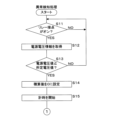
- ⁇ Anomaly detection processing> 5 and 6 are flowcharts showing the procedure of abnormality detection processing.
- difference values regarding output voltage values are integrated.
- the storage unit 45 stores integrated data indicating an integrated value of difference values.
- the integrated value indicated by the integrated data is changed by the control unit 46.
- the storage unit 45 stores frequency data indicating the number of abnormality detections.
- the number of abnormality detections indicated by the number of times data is changed by the control unit 46.
- the number of abnormality detections indicated by the number of times data is set to zero.
- the control unit 46 first determines whether the relay contact 30 is on (step S11). If relay contact 30 is not on, relay contact 30 is off. If the control unit 46 determines that the relay contact 30 is not turned on (S11: NO), it executes step S11 again and waits until the relay contact 30 is turned on.
- step S12 the control unit 46 acquires power supply voltage information from the A/D conversion unit 41 (step S12). Since the power supply voltage information indicates the power supply voltage value, acquiring the power supply voltage information corresponds to acquiring the power supply voltage value.
- step S13 the control unit 46 determines whether the power supply voltage value indicated by the power supply voltage information acquired in step S12 is equal to or higher than a predetermined voltage value (step S13).
- the predetermined voltage value is a constant value and is set in advance.
- the control unit 46 determines that the power supply voltage value is less than the predetermined voltage value (S13: NO)
- step S11 the control unit 46 waits until the power supply voltage value becomes equal to or higher than a predetermined voltage value while the relay contact 30 is on.
- control unit 46 determines that the power supply voltage value is equal to or higher than the predetermined voltage value (S13: YES)
- the control unit 46 sets the integrated value indicated by the integrated data to 0 (step S14), and instructs the timer 43 to start timing. (Step S15).
- step S15 the control unit 46 acquires output voltage information from the A/D conversion unit 42 (step S16). Since the output voltage information indicates the output voltage value, acquiring the output voltage information corresponds to acquiring the output voltage value.
- step S17 the control unit 46 determines whether the output voltage value indicated by the output voltage information acquired in step S16 is a value outside a preset setting range (step S17).
- the setting range corresponds to a predetermined range.
- the control unit 46 determines whether the output voltage value indicated by the output voltage information acquired in step S16 is less than the lower limit of the set range. (Step S18). Regarding step S18, if the output voltage value is not less than the lower limit of the set range, the output voltage value exceeds the upper limit of the set range.
- control unit 46 determines that the output voltage value is less than the lower limit value (S18: YES), it calculates the difference value between the output voltage value and the lower limit value (Step S19).
- the control unit 46 determines that the output voltage value is not less than the lower limit value (S18: NO)
- the control unit 46 calculates the difference value between the output voltage value and the upper limit value (Step S20).
- the output voltage value is the output voltage value indicated by the output voltage information acquired in step S16.
- the upper limit value and the lower limit value are the upper limit value and lower limit value of the setting range, respectively.
- the difference value is an absolute value.
- step S21 the control unit 46 increases the integrated value indicated by the integrated data by the difference value calculated in step S19 or step S20 (step S21).
- the integrated value is calculated based on the difference value.
- the difference value is calculated based on the output voltage value. Therefore, the integrated value is a value based on the output voltage value. If the output voltage value is not outside the setting range (S17: NO), or after executing step S21, the control unit 46 determines whether the time measured by the timer 43 is equal to or longer than a predetermined time. is determined (step S22).
- the predetermined time is a constant value and is set in advance.
- control unit 46 determines that the measured time is less than the predetermined time (S22: NO), it executes step S16 again.
- the control unit 46 repeatedly acquires the output voltage information (output voltage value) until the measured time reaches a predetermined time or more. If the output voltage value is outside the set range, the integrated value indicated by the integrated data is increased by the difference value.
- the control unit 46 instructs the timer 43 to end the time count. After that, the control unit 46 executes the abnormality detection process again.
- step S23 the control unit 46 determines whether an abnormality has occurred in the relay contact 30 (step S24).
- step S24 the control unit 46 determines that an abnormality has occurred when the integrated value indicated by the integrated data is equal to or greater than the integrated threshold. If the integrated value indicated by the integrated data is less than the integrated threshold, the control unit 46 determines that no abnormality has occurred.
- the integration threshold is a constant positive value and is set in advance.
- the control unit 46 reads the threshold number of times corresponding to the number of abnormality detections indicated by the number of times data from the number of times change table T2 (step S26).
- the control unit 46 lowers the threshold number of times shown in the threshold number of times table T1 to the threshold number of times read out in step S26 (step S27).
- the threshold number of times in the threshold number of times table T1 decreases.
- step S27 the timing of notifying the replacement of the relay 20 is brought forward. If the control unit 46 determines that no abnormality has occurred (S24: NO), or after executing step S27, it ends the abnormality detection process. After finishing the abnormality detection process, the control unit 46 executes the abnormality detection process again.
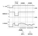
- FIG. 7 is a timing chart showing an example of the operation of the microcomputer 24.
- FIG. 7 shows changes in the state of the relay contact 30, changes in the power supply voltage value, and changes in the output voltage value. Time is shown on the horizontal axis of each of the three transitions.
- Vp indicates a predetermined voltage value.
- V1 and V2 indicate the upper limit value and lower limit value of the setting range, respectively.
- the acquisition period is a period from when the timer 43 starts counting until the time measured by the timer 43 reaches a predetermined time. The acquisition period corresponds to a predetermined period.
- the control unit 46 does not acquire output voltage information.
- the predetermined voltage value Vp is less than or equal to the power supply voltage value when the starter 12 is not operating.
- the predetermined voltage value Vp exceeds the power supply voltage value when the starter 12 is operating. Therefore, while the starter 12 is operating, the power supply voltage value is less than the predetermined voltage value Vp, so the control unit 46 does not acquire output voltage information.
- the control unit 46 When the relay contact 30 is on and the power supply voltage value indicated by the acquired power supply voltage information is equal to or higher than a predetermined voltage value, the control unit 46 starts the acquisition period by causing the timer 43 to start timing.
- the control unit 46 repeatedly acquires output voltage information (output voltage value) during the acquisition period.
- the acquisition interval at which the control unit 46 acquires the output voltage information is constant.
- the control unit 46 determines whether the output voltage value indicated by the acquired output voltage information is a value outside the set range. If the control unit 46 determines that the output voltage value is outside the set range, it calculates the difference between the output voltage value and a value close to the output voltage value among the upper and lower limit values of the set range. .
- the control unit 46 determines that no abnormality has occurred in the relay contact 30. If the number of output voltage values outside the setting range is 1 among the plurality of output voltage values acquired by the control unit 46 during the predetermined period, the integrated value is the output voltage value outside the setting range. It matches the difference value calculated using the value. If the number of output voltage values outside the setting range is two or more among the plurality of output voltage values acquired by the control unit 46 during the predetermined period, the control unit 46 Calculate the integrated value of multiple difference values. When the integrated value is equal to or greater than the integrated threshold, the control unit 46 determines that an abnormality has occurred in the relay contact 30 and detects the abnormality in the relay contact 30.
- the acquisition period is repeatedly started.
- the first acquisition period all the output voltage values acquired by the control unit 46 are within the set range, so the integrated value is 0.
- the control unit 46 determines that no abnormality has occurred in the relay contact 30.
- the plurality of output voltage values acquired by the control unit 46 during the predetermined period include an output voltage value outside the setting range, and the integrated value exceeds the integration threshold, so the control unit 46 detects an abnormality in the relay contact 30.
- the relay contact 30 Even when the relay contact 30 is on, if the power supply voltage value is less than a predetermined voltage value, an erroneous determination regarding an abnormality may be made. ).
- the relay contact 30 if the NO terminal 30b or the conductor 30c is deformed, or if the NO terminal 30b or the conductor 30c is worn out, the resistance value between the COM terminal 30a and the NO terminal 30b when the relay contact 30 is on will change. There is a possibility that it will decrease. In this case, the output voltage value exceeds the upper limit of the setting range.
- the control unit 46 of the microcomputer 24 determines whether an abnormality has occurred in the relay contact 30 based on the integrated value.
- the value used to determine whether or not an abnormality has occurred is not limited to the integrated value.
- differences between the second embodiment and the first embodiment will be explained.
- Other configurations other than those described below are the same as those of the first embodiment, so the same reference numerals as those of the first embodiment will be given to the components that are common to the first embodiment, and the explanation thereof will be omitted.
- FIG. 8 is a flowchart showing the procedure of abnormality detection processing in the second embodiment.
- the control unit 46 of the microcomputer 24 executes steps S11 to S13, S15, S16, and S22 to S27 as in the first embodiment.
- steps S11 to S13, S15, S16, S22, S23, and S25 to S27 will be omitted.
- step S15 when the control unit 46 determines that the power supply voltage value indicated by the power supply voltage information acquired in step S12 is equal to or higher than the predetermined voltage value (S13: YES), the control unit 46 executes step S15. After executing step S16, the control unit 46 executes step S22. Therefore, when the relay contact 30 is on and the power supply voltage value is a predetermined voltage value or more, the control unit 46 controls the output voltage information (output voltage value) until the timer 43 measures the predetermined time or more. get repeatedly. As described in the description of the first embodiment, the period from 0 to the predetermined time when the timer 43 measures time is the acquisition period.
- step S23 the control unit 46 determines whether or not an abnormality has occurred in the relay contact 30, similarly to the first embodiment (step S24).
- step S24 of the second embodiment the control unit 46 determines whether the number of output voltage values outside the setting range included in the plurality of output voltage values indicated by the plurality of output voltage information acquired during the acquisition period is equal to or greater than a predetermined number. , it is determined that an abnormality has occurred in the relay contact 30. If the number of output voltage values outside the setting range included in the plurality of output voltage values indicated by the plurality of output voltage information acquired during the acquisition period is less than a predetermined number, the control unit 46 determines that an abnormality has occurred in the relay contact 30. It is determined that it has not been done.
- the predetermined number is a constant positive value and is set in advance.
- control unit 46 determines that an abnormality has occurred in the relay contact 30 (S24: YES), it sequentially executes steps S25 to S27. Therefore, the control unit 46 increments the number of abnormality detections indicated by the number of times data by one. The control unit 46 lowers the threshold number of times in the threshold number of times table T1 according to the number of abnormality detections after the change.
- step S26 After executing step S26, or if it is determined that no abnormality has occurred in the relay contact 30 (S24: NO), the control unit 46 ends the abnormality detection process. After finishing the abnormality detection process, the control unit 46 executes the abnormality detection process again.
- the control unit 46 acquires a plurality of output voltage values during the acquisition period. If the number of output voltage values outside the set range included in the plurality of acquired output voltage values exceeds a predetermined number, the control unit 46 detects an abnormality in the relay contact 30. In the example of FIG. 7, the number of output voltage values outside the set range is zero for the first acquisition period. Therefore, the control unit 46 does not detect any abnormality. Regarding the second acquisition period, the number of output voltage values outside the set range is four. If the predetermined number is set to a value of 4 or less, the control unit 46 detects an abnormality. If the predetermined number is set to a value exceeding 4, the control unit 46 does not detect an abnormality.
- the power supply control device 11 in the second embodiment similarly achieves the effects of the power supply control device 11 in the first embodiment except for the effect obtained by detecting an abnormality using the integrated value.
- the transistor 23 functions as a switch that can be turned on or off by the switching unit 40 of the microcomputer 24. Therefore, the transistor 23 is not limited to an NPN type bipolar transistor, but may be an N-channel type FET (Field Effect Transistor), for example.
- the end of the conductor 30c may be connected to the NO terminal 30b instead of the COM terminal 30a. In this case, the conductor 30c can rotate about the NO terminal 30b. When no current is flowing through the coil 31, the conductor 30c is separated from the COM terminal 30a by the spring. At this time, relay contact 30 is off. When current is flowing through the coil 31, the conductor 30c contacts the COM terminal 30a. At this time, relay contact 30 is on.
- Embodiments 1 and 2 can be combined with each other, and new technical features can be formed by combining them.
- the disclosed embodiments 1 and 2 are illustrative in all respects and should not be considered restrictive.
- the scope of the present invention is indicated by the scope of the claims, not the meaning described above, and is intended to include meanings equivalent to the scope of the claims and all changes within the scope.
- the claims may include multiple dependent claims that are dependent on multiple claims. Multiple dependent claims may be written that are dependent on multiple dependent claims. Even if a multiple dependent claim that is dependent on a multiple dependent claim is not written, this does not limit the writing of the multiple dependent claim that is dependent on the multiple dependent claim.
Landscapes
- Physics & Mathematics (AREA)
- General Physics & Mathematics (AREA)
- Engineering & Computer Science (AREA)
- Power Engineering (AREA)
- Mechanical Engineering (AREA)
- Direct Current Feeding And Distribution (AREA)
- Testing Of Short-Circuits, Discontinuities, Leakage, Or Incorrect Line Connections (AREA)
- Testing Electric Properties And Detecting Electric Faults (AREA)
- Protection Of Static Devices (AREA)
Abstract
Description
本出願は、2022年4月4日出願の日本出願第2022-062539号に基づく優先権を主張し、前記日本出願に記載された全ての記載内容を援用するものである。
リレー接点に関して、導体が端子に接触することによって、状態はオフからオンに切替わる。導体が端子から離れることによって、状態はオンからオフに切替わる。導体若しくは端子が変形した場合、又は、導体若しくは端子が摩耗した場合、リレー接点を介して流れる電流の通流が不安定となる可能性がある。結果、リレー接点において異常が発生する可能性がある。特許文献1では、リレー接点の異常の検知について考慮されていない。
上記の態様によれば、リレー接点の異常を検知することができる。
最初に本開示の実施態様を列挙して説明する。以下に記載する実施形態の少なくとも一部を任意に組み合わせてもよい。
本開示の実施形態に係る電源システムの具体例を、以下に図面を参照しつつ説明する。なお、本開示はこれらの例示に限定されるものではなく、請求の範囲によって示され、請求の範囲と均等の意味及び範囲内での全ての変更が含まれることが意図される。
図1は、実施形態1における電源システム1の要部構成を示すブロック図である。電源システム1は車両Cに搭載されている。電源システム1は、直流電源10、給電制御装置11、スタータ12及び負荷13を備える。直流電源10は、例えばバッテリである。負荷13は、例えばECU(Electronic Control Unit)である。
給電制御装置11は、リレー20に加えて、電源電圧検出回路21、出力電圧検出回路22、トランジスタ23及びマイクロコンピュータ(以下、マイコンという)24を有する。電源電圧検出回路21は分圧抵抗21a,21bを有する。出力電圧検出回路22は分圧抵抗22a,22bを有する。トランジスタ23は、NPN型のバイポーラトランジスタである。
図2はマイコン24の要部構成を示すブロック図である。マイコン24は、切替え部40、A/D変換部41,42、タイマ43、報知部44、記憶部45及び制御部46を有する。これらは内部バス47に接続されている。切替え部40は、更に、トランジスタ23のベースに接続されている。A/D変換部41は、更に、2つの分圧抵抗21a,21b間の接続ノードに接続されている。A/D変換部42は、更に、2つの分圧抵抗22a,22b間の接続ノードに接続されている。
報知部44は、制御部46の指示に従って、報知を行う。具体的には、報知部44は、ランプの点灯、又は、メッセージの表示を行うことによって、リレー20の交換を通知する。なお、報知部44は、リレー20の交換を示すデータを送信することによって報知を行ってもよい。
図4は切替え処理の手順を示すフローチャートである。切替え処理では、制御部46は、まず、リレー接点30をオンに切替えるか否かを判定する(ステップS1)。マイコン24は、例えば、リレー接点30のオンへの切替えを指示するオン信号が入力されるオン信号入力部を有する。この構成では、オン信号入力部にオン信号が入力された場合、制御部46は、リレー接点30をオンに切替えると判定する。オン信号入力部にオン信号が入力されなかった場合、制御部46は、リレー接点30をオンに切替えないと判定する。
図5及び図6は異常検知処理の手順を示すフローチャートである。異常検知処理では、出力電圧値に関する差分値を積算する。記憶部45には、差分値の積算値を示す積算データが記憶されている。積算データが示す積算値は制御部46によって変更される。記憶部45には、異常検知回数を示す回数データが記憶されている。回数データが示す異常検知回数は制御部46によって変更される。給電制御装置11が製造された時点又はリレー20が交換された時点では、回数データが示す異常検知回数は0に設定されている。
実施形態1では、マイコン24の制御部46は、積算値に基づいて、リレー接点30において異常が発生しているか否かを判定している。しかしながら、異常が発生しているか否かの判定に用いる値は、積算値に限定されない。
以下では、実施形態2について、実施形態1と異なる点を説明する。後述する構成を除く他の構成については、実施形態1と共通しているため、実施形態1と共通する構成部には実施形態1と同一の参照符号を付してその説明を省略する。
図8は、実施形態2における異常検知処理の手順を示すフローチャートである。実施形態2における異常検知処理では、マイコン24の制御部46は、実施形態1と同様に、ステップS11~S13,S15,S16,S22~S27を実行する。実施形態1,2における異常検知処理を比較した場合、ステップS24の内容が異なる。このため、ステップS11~S13,S15,S16,S22,S23,S25~S27の詳細な説明を省略する。
実施形態2における給電制御装置11は、実施形態1における給電制御装置11が奏する効果の中で、積算値を用いて異常を検知することによって得られる効果を除く他の効果を同様に奏する。
実施形態1,2において、トランジスタ23は、マイコン24の切替え部40によってオン又はオフに切替えることができるスイッチとして機能すれば、問題はない。このため、トランジスタ23は、NPN型のバイポーラトランジスタに限定されず、例えば、Nチャネル型のFET(Field Effect Transistor)であってもよい。また、リレー接点30に関して、COM端子30aではなく、NO端子30bに導体30cの端部が接続されてもよい。この場合、導体30cは、NO端子30bを基点として回転することが可能である。コイル31を介して電流が流れていない場合、導体30cは、バネによってCOM端子30aから離れている。このとき、リレー接点30はオフである。コイル31を介して電流が流れている場合、導体30cは、COM端子30aに接触する。このときリレー接点30はオンである。
開示された実施形態1,2は全ての点で例示であって、制限的なものではないと考えられるべきである。本発明の範囲は、上記した意味ではなく、請求の範囲によって示され、請求の範囲と均等の意味及び範囲内での全ての変更が含まれることが意図される。
10 直流電源
11 給電制御装置
12 スタータ
13 負荷
20 リレー
21 電源電圧検出回路
21a,21b,22a,22b 分圧抵抗
22 出力電圧検出回路
23 トランジスタ
24 マイコン
30 リレー接点
30a COM端子
30b NO端子
30c 導体
31 コイル
40 切替え部
41,42 A/D変換部
43 タイマ
44 報知部
45 記憶部
46 制御部(処理部)
47 内部バス
A 記憶媒体
C 車両
P コンピュータプログラム
T1 閾値回数テーブル
T2 回数変更テーブル
Claims (8)
- リレー接点を介した給電を制御する給電制御装置であって、
処理を実行する処理部を備え、
前記処理部は、
前記リレー接点がオンである場合に、前記リレー接点の下流側の一端の第1電圧値を取得し、
取得した第1電圧値に基づいて、前記リレー接点にて異常が発生しているか否かを判定する
給電制御装置。 - 前記処理部は、
前記リレー接点がオンである場合に、所定期間中に前記第1電圧値を繰り返し取得し、
前記第1電圧値を取得する都度、取得した第1電圧値が所定範囲外の値であるか否かを判定し、
前記第1電圧値が前記所定範囲外の値であると判定した場合、前記所定範囲の上限値及び下限値の中で前記第1電圧値に近い値と、前記第1電圧値との差分値を算出し、
前記所定期間中に算出した差分値の積算値が積算閾値以上である場合、前記リレー接点にて、前記異常が発生していると判定する
請求項1に記載の給電制御装置。 - 前記処理部は、
前記リレー接点がオンである場合に、所定期間中に前記第1電圧値を繰り返し取得し、
前記所定期間中に取得した複数の第1電圧値に含まれている所定範囲外の第1電圧値の数が所定数を超えている場合、前記リレー接点にて、前記異常が発生していると判定する
請求項1に記載の給電制御装置。 - 前記処理部は、
前記リレー接点の上流側の一端の第2電圧値を取得し、
前記リレー接点がオンである場合にて、取得した第2電圧値が所定電圧値以上であるとき、前記第1電圧値を取得する
請求項1から請求項3のいずれか1項に記載の給電制御装置。 - 前記処理部は、
前記リレー接点がオン又はオフに切替わった切替え回数が閾値回数以上であるか否かを判定し、
前記リレー接点にて前記異常が発生していると判定した異常検知回数に応じて、前記閾値回数を低下させる
請求項1から請求項3のいずれか1項に記載の給電制御装置。 - 前記リレー接点は、直流電源から負荷への給電経路に配置されている
請求項1から請求項3のいずれか1項に記載の給電制御装置。 - リレー接点を介して給電を制御する給電制御方法であって、
前記リレー接点がオンである場合にて、前記リレー接点の下流側の一端の第1電圧値を取得するステップと、
取得した第1電圧値に基づいて、前記リレー接点にて異常が発生しているか否かを判定するステップと
をコンピュータが実行する給電制御方法。 - 電流が流れるリレー接点がオンである場合に、前記リレー接点の下流側の一端の第1電圧値を取得するステップと、
取得した第1電圧値に基づいて、前記リレー接点にて異常が発生しているか否かを判定するステップと
をコンピュータに実行させるためのコンピュータプログラム。
Priority Applications (2)
| Application Number | Priority Date | Filing Date | Title |
|---|---|---|---|
| US18/852,571 US20250218713A1 (en) | 2022-04-04 | 2023-04-03 | Power supply control device, power supply control method, and computer program |
| CN202380028517.9A CN118829889A (zh) | 2022-04-04 | 2023-04-03 | 供电控制装置、供电控制方法及计算机程序 |
Applications Claiming Priority (2)
| Application Number | Priority Date | Filing Date | Title |
|---|---|---|---|
| JP2022062539A JP7815945B2 (ja) | 2022-04-04 | 2022-04-04 | 給電制御装置、給電制御方法及びコンピュータプログラム |
| JP2022-062539 | 2022-04-04 |
Publications (1)
| Publication Number | Publication Date |
|---|---|
| WO2023195437A1 true WO2023195437A1 (ja) | 2023-10-12 |
Family
ID=88242957
Family Applications (1)
| Application Number | Title | Priority Date | Filing Date |
|---|---|---|---|
| PCT/JP2023/013762 Ceased WO2023195437A1 (ja) | 2022-04-04 | 2023-04-03 | 給電制御装置、給電制御方法及びコンピュータプログラム |
Country Status (4)
| Country | Link |
|---|---|
| US (1) | US20250218713A1 (ja) |
| JP (1) | JP7815945B2 (ja) |
| CN (1) | CN118829889A (ja) |
| WO (1) | WO2023195437A1 (ja) |
Citations (7)
| Publication number | Priority date | Publication date | Assignee | Title |
|---|---|---|---|---|
| JP2014190960A (ja) * | 2013-03-28 | 2014-10-06 | Gs Yuasa Corp | スイッチ故障判定装置、蓄電装置およびスイッチ故障判定方法 |
| US20140354287A1 (en) * | 2014-08-14 | 2014-12-04 | Solar Turbines Incorporated | Apparatus for testing an electromechanical relay |
| WO2016063313A1 (ja) * | 2014-10-22 | 2016-04-28 | パナソニックIpマネジメント株式会社 | 安定化電源装置 |
| JP2017164411A (ja) * | 2016-03-18 | 2017-09-21 | リンナイ株式会社 | 食器洗浄乾燥機 |
| JP2018536855A (ja) * | 2016-02-19 | 2018-12-13 | エルジー・ケム・リミテッド | スイッチ部品の故障診断装置及び方法 |
| WO2019181495A1 (ja) * | 2018-03-23 | 2019-09-26 | 株式会社オートネットワーク技術研究所 | 制御装置、制御方法及びコンピュータプログラム |
| WO2021251118A1 (ja) * | 2020-06-10 | 2021-12-16 | 株式会社オートネットワーク技術研究所 | 電線保護装置、電線保護方法及びコンピュータプログラム |
-
2022
- 2022-04-04 JP JP2022062539A patent/JP7815945B2/ja active Active
-
2023
- 2023-04-03 US US18/852,571 patent/US20250218713A1/en active Pending
- 2023-04-03 WO PCT/JP2023/013762 patent/WO2023195437A1/ja not_active Ceased
- 2023-04-03 CN CN202380028517.9A patent/CN118829889A/zh active Pending
Patent Citations (7)
| Publication number | Priority date | Publication date | Assignee | Title |
|---|---|---|---|---|
| JP2014190960A (ja) * | 2013-03-28 | 2014-10-06 | Gs Yuasa Corp | スイッチ故障判定装置、蓄電装置およびスイッチ故障判定方法 |
| US20140354287A1 (en) * | 2014-08-14 | 2014-12-04 | Solar Turbines Incorporated | Apparatus for testing an electromechanical relay |
| WO2016063313A1 (ja) * | 2014-10-22 | 2016-04-28 | パナソニックIpマネジメント株式会社 | 安定化電源装置 |
| JP2018536855A (ja) * | 2016-02-19 | 2018-12-13 | エルジー・ケム・リミテッド | スイッチ部品の故障診断装置及び方法 |
| JP2017164411A (ja) * | 2016-03-18 | 2017-09-21 | リンナイ株式会社 | 食器洗浄乾燥機 |
| WO2019181495A1 (ja) * | 2018-03-23 | 2019-09-26 | 株式会社オートネットワーク技術研究所 | 制御装置、制御方法及びコンピュータプログラム |
| WO2021251118A1 (ja) * | 2020-06-10 | 2021-12-16 | 株式会社オートネットワーク技術研究所 | 電線保護装置、電線保護方法及びコンピュータプログラム |
Also Published As
| Publication number | Publication date |
|---|---|
| US20250218713A1 (en) | 2025-07-03 |
| JP7815945B2 (ja) | 2026-02-18 |
| JP2023152493A (ja) | 2023-10-17 |
| CN118829889A (zh) | 2024-10-22 |
Similar Documents
| Publication | Publication Date | Title |
|---|---|---|
| KR101504429B1 (ko) | 네거티브 온도 계수 서미스터를 이용한 온도 측정 장치 | |
| CN107276137A (zh) | 充电装置 | |
| JP2017118791A (ja) | 給電制御装置 | |
| JP2019169873A (ja) | 制御装置、制御方法及びコンピュータプログラム | |
| US11222526B2 (en) | Two-wire transmitter | |
| JP3707355B2 (ja) | 電流検出回路 | |
| JP6981568B2 (ja) | 給電制御装置 | |
| EP3116129A1 (en) | Preventive apparatus | |
| WO2023195437A1 (ja) | 給電制御装置、給電制御方法及びコンピュータプログラム | |
| JP5524096B2 (ja) | 過電流保護装置 | |
| JP2001216878A (ja) | スイッチ状態監視回路及びスイッチ | |
| CN110676804B (zh) | 检测电路与使用其的开关模块 | |
| JP7067033B2 (ja) | 給電制御装置、給電制御方法及びコンピュータプログラム | |
| JP2022162932A (ja) | レベルシフト回路、レベル判定装置及びレベル判定方法 | |
| WO2023007558A1 (ja) | 電力供給装置 | |
| CN213484505U (zh) | 短路保护电路 | |
| JP7196826B2 (ja) | スイッチ装置、電流判定方法及びコンピュータプログラム | |
| JP2000111589A (ja) | 半導体集積回路 | |
| CN102608525A (zh) | 电压极限测试系统及辅助测试治具 | |
| WO2018168392A1 (ja) | 給電制御装置、給電制御方法及びコンピュータプログラム | |
| JP7460300B2 (ja) | センサ制御装置およびセンサ制御装置の製造方法 | |
| JP5696884B2 (ja) | 接点入力装置 | |
| JP2023102646A (ja) | 電気機器及び車載システム | |
| JPH08275263A (ja) | 過電流保護装置 | |
| JP2000188828A (ja) | コンデンサ放電回路 |
Legal Events
| Date | Code | Title | Description |
|---|---|---|---|
| 121 | Ep: the epo has been informed by wipo that ep was designated in this application |
Ref document number: 23784723 Country of ref document: EP Kind code of ref document: A1 |
|
| WWE | Wipo information: entry into national phase |
Ref document number: 202380028517.9 Country of ref document: CN |
|
| WWE | Wipo information: entry into national phase |
Ref document number: 18852571 Country of ref document: US |
|
| NENP | Non-entry into the national phase |
Ref country code: DE |
|
| 122 | Ep: pct application non-entry in european phase |
Ref document number: 23784723 Country of ref document: EP Kind code of ref document: A1 |
|
| WWP | Wipo information: published in national office |
Ref document number: 18852571 Country of ref document: US |