WO2023195048A1 - 音声拡張現実オブジェクト再生装置、情報端末システム - Google Patents
音声拡張現実オブジェクト再生装置、情報端末システム Download PDFInfo
- Publication number
- WO2023195048A1 WO2023195048A1 PCT/JP2022/017058 JP2022017058W WO2023195048A1 WO 2023195048 A1 WO2023195048 A1 WO 2023195048A1 JP 2022017058 W JP2022017058 W JP 2022017058W WO 2023195048 A1 WO2023195048 A1 WO 2023195048A1
- Authority
- WO
- WIPO (PCT)
- Prior art keywords
- augmented reality
- audio
- playback device
- reality object
- information terminal
- Prior art date
- Legal status (The legal status is an assumption and is not a legal conclusion. Google has not performed a legal analysis and makes no representation as to the accuracy of the status listed.)
- Ceased
Links
Images







Classifications
-
- H—ELECTRICITY
- H04—ELECTRIC COMMUNICATION TECHNIQUE
- H04R—LOUDSPEAKERS, MICROPHONES, GRAMOPHONE PICK-UPS OR LIKE ACOUSTIC ELECTROMECHANICAL TRANSDUCERS; ELECTRIC HEARING AIDS; PUBLIC ADDRESS SYSTEMS
- H04R1/00—Details of transducers, loudspeakers or microphones
- H04R1/20—Arrangements for obtaining desired frequency or directional characteristics
- H04R1/32—Arrangements for obtaining desired frequency or directional characteristics for obtaining desired directional characteristic only
- H04R1/40—Arrangements for obtaining desired frequency or directional characteristics for obtaining desired directional characteristic only by combining a number of identical transducers
-
- H—ELECTRICITY
- H04—ELECTRIC COMMUNICATION TECHNIQUE
- H04R—LOUDSPEAKERS, MICROPHONES, GRAMOPHONE PICK-UPS OR LIKE ACOUSTIC ELECTROMECHANICAL TRANSDUCERS; ELECTRIC HEARING AIDS; PUBLIC ADDRESS SYSTEMS
- H04R3/00—Circuits for transducers
-
- H—ELECTRICITY
- H04—ELECTRIC COMMUNICATION TECHNIQUE
- H04S—STEREOPHONIC SYSTEMS
- H04S7/00—Indicating arrangements; Control arrangements, e.g. balance control
Definitions
- the present invention relates to an audio augmented reality object playback device and an information terminal system using the audio augmented reality object playback device.
- an audio augmented reality object playback device which is worn on the user's head, outputs audio based on stereophonic technology from an audio output device such as a speaker, and displays various information on a display screen in front of the user.
- An audio augmented reality object playback device is known that displays an audio augmented reality object.
- Patent Document 1 discloses a technology related to stereophonic sound technology. That is, Patent Document 1 is a three-dimensional sound signal reproducing device that generates and reproduces a three-dimensional sound signal, and performs Fourier transform along the azimuth angle on the head-related transfer function measured at the first distance. Afterwards, a Hankel function is used to convert the first distance to a second distance, and an inverse Fourier transform is performed using the order of the Hankel function as a variable to obtain the head-related transfer function at the second distance. and a second processing unit that generates the three-dimensional sound signal by applying the head-related transfer function at the second distance to the input acoustic signal as a filter. Disclosed is a three-dimensional sound signal reproducing device characterized by the following.
- Patent Document 1 suppresses quality deterioration caused by discontinuous points and reproduces high-quality stereophonic sound even when using a method of synthesizing HRTFs at arbitrary distances on the horizontal plane. It is said to have the effect of making it possible. Further, Patent Document 1 discloses that a stereophonic sound signal reproducing device with a high sense of presence can be realized in a horizontal plane where human perception accuracy is high.
- Patent Document 2 discloses an audio processing device. That is, Patent Document 2 discloses a microphone array having microphone elements having at least two channels, a band dividing section that divides a signal from the microphone array into a plurality of frequency bands for each channel, and a band dividing signal obtained by dividing the band. a sound source localization unit that estimates the sound source direction from the sound source direction; a sound source separation unit that emphasizes the band division signal for each of the estimated sound source directions; and a sound source separation unit that uses the emphasized band division signal and information on the estimated sound source direction.
- a sound source duplication determination unit that determines whether the band-split signal is a signal from a plurality of sound sources or a single sound source
- a sound source search unit that performs a sound source search using the signal determined to be the band-split signal from the single sound source
- Patent Document 2 determines whether multiple sound sources overlap and uses only the band-divided signal in which a single sound source is sounding for sound source localization. Do not use lost band components. As a result, the technology disclosed in Patent Document 2 is said to be able to accurately determine the direction in which voice or music is being played.
- the audio augmented reality object playback device As an example of how the audio augmented reality object playback device is used by the user, the following method can be considered. That is, the user maps an object (an information terminal or an application) as a virtual object onto the virtual space of the audio augmented reality object playback device, and operates the mapped object using the audio augmented reality object playback device.
- the user maps an object (an information terminal or an application) as a virtual object onto the virtual space of the audio augmented reality object playback device, and operates the mapped object using the audio augmented reality object playback device.
- the user may not be able to easily perform mapping, resulting in a lack of user convenience. Note that it is considered that Patent Document 1 and Patent Document 2 described above do not disclose such a mapping technique.
- the present invention provides an audio augmented reality object playback device that is designed to improve user convenience and can perform mapping easily, and an information terminal system using the audio augmented reality object playback device.
- the purpose is to
- the audio augmented reality object playback device is capable of mapping objects in virtual space.
- the audio augmented reality object playback device includes a processor.
- the processor maps the information terminal or an application of the information terminal to a position in a virtual space corresponding to the position of the information terminal based on the audio output and input from the information terminal.
- the information terminal system includes one or more information terminals and an audio augmented reality object playback device that can map objects in a virtual space.
- the audio augmented reality object playback device includes a processor.
- the processor maps the information terminal or an application of the information terminal to a position in a virtual space corresponding to the position of the information terminal based on the audio output and input from the information terminal.
- an audio augmented reality object playback device that improves user convenience and can easily perform mapping, and an information terminal system using the audio augmented reality object playback device. be done.
- FIG. 2 is a block diagram used to explain an example of the configuration of a head-mounted display according to the first embodiment.
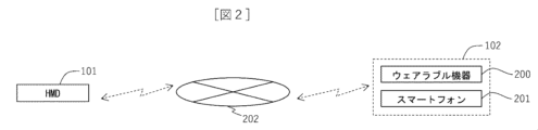
- FIG. 3 is a diagram used to explain an example of connection for communication with an information terminal.
- FIG. 2 is a diagram used to explain an example of the structure of a head-mounted display.
- FIG. 2 is a diagram used to explain an example of the structure of a head-mounted display.
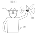
- FIG. 3 is a diagram used to explain an example of a method for a user to map a target.
- FIG. 3 is a diagram used to explain an example of a method for a user to map a target.
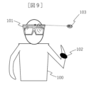
- FIG. 3 is a diagram used to explain an example of a method for a user to map a target.
- FIG. 3 is a diagram used to explain an example of a method for a user to map a target.
- FIG. 3 is a block diagram used to explain an example of connection for communication with an information terminal.
- FIG. 2 is a diagram used to explain an example of the
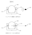
- FIG. 3 is a diagram used to explain a sound source of audio heard during mapping.
- FIG. 6 is a diagram used to explain the sound source of audio that can be heard after mapping.
- FIG. 3 is a diagram used to explain the relationship between a virtual sound source and stereophonic sound in a virtual space.
- FIG. 3 is a diagram used to explain the position of a virtual sound source in a local coordinate system.
- FIG. 3 is a diagram used to explain the position of a virtual sound source in a world coordinate system.
- 3 is a flowchart used to explain an example of mapping processing.
- 3 is a flowchart used to explain an example of mapping processing.
- 3 is a flowchart used to explain an example of mapping processing.
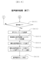
- 3 is a flowchart used to explain an example of voice operation processing.
- FIG. 3 is a flowchart used to explain an example of voice operation processing.
- 3 is a flowchart used to explain an example of voice operation processing.
- FIG. 3 is a diagram used to explain an example of data input/output between a head-mounted display and an information terminal during voice operation.
- FIG. 7 is a block diagram used to explain an example of the configuration of an audio augmented reality object playback device according to a second embodiment.
- mapping technology according to the present invention can contribute to "9. Create a foundation for industry and technological innovation" of the Sustainable Development Goals (SDGs) advocated by the United Nations.
- SDGs Sustainable Development Goals
- FIG. 1 is a block diagram used to explain an example of the configuration of an HMD.
- the HMD 101 can map an object on the virtual space and generate an icon of the mapped object. The user can then select the generated icon and operate the mapped object.
- the HMD 101 includes a control unit 10, a ROM 11, a RAM 12, a storage unit 13, a camera 14, a display 15, a microphone 16, a speaker 17, a button 18, and a touch sensor 19. , is provided.
- the control unit 10 controls the entire HMD 101 according to a predetermined operation program.
- the control unit 10 sends and receives various commands and data to and from each component block in the HMD 101 via a system bus that is a data communication path.
- the control unit 10 may be a main body that executes predetermined processing, and is configured by, for example, a CPU (Central Processing Unit), but may also be configured by using a semiconductor device such as a GPU (Graphics Processing Unit).
- the ROM 11 is constituted by a suitable storage device such as a flash ROM, and stores data such as programs related to the operation of the HMD 101 and processes to be executed.
- the RAM 12 is a memory used when the control unit 10 executes predetermined processing.
- the storage unit 13 can be configured from an appropriate storage device such as a hard disk drive (HDD), and can store data.
- HDD hard disk drive
- the camera 14 is provided at an appropriate position so that it can capture external images.
- the camera 14 may be provided, for example, to be able to obtain information outside the user's field of view.
- the display 15 (display unit) is provided on the front side and displays images. For example, an image acquired by the camera 14 may be displayed on the display 15, and a user wearing the HMD 101 can visually obtain information by viewing the image acquired by the camera 14 displayed on the display 15. Good too. Further, as will be described in detail later, the display 15 can display icons generated by performing mapping processing, but the display 15 also displays other information (for example, information regarding the output volume from the HMD 101, (information acquired from the outside through wireless communication, etc.) may be displayed as appropriate.
- the display 15 can have an appropriate structure.
- the display 15 may be of a non-transmissive type or a transmissive type, for example.
- the HMD 101 may have a structure in which one display 15 is placed in front of each of the user's eyes, or may have a structure in which one display 15 is placed to cover both eyes of the user. good.
- the microphone 16 is a voice input device, and in this embodiment, it is provided at an appropriate position so that the voice of the user wearing the HMD 101 can be input.
- the microphone 16 may be provided, for example, via a member that extends to the mouth.
- the speaker 17 is an audio output device and outputs information through audio.
- the speaker 17 is provided at an appropriate position so that the user can hear the output audio.
- an audio output device different from the speaker 17 may be used; for example, headphones may be provided as the audio output device.
- the HMD 101 may be configured so that the user can perform various operations such as adjusting the volume and image quality and setting communication using the buttons 18 and the touch sensor 19.
- the desired operation content may be achieved by pressing the button 18 corresponding to the user's desired operation, and the position and number of the buttons 18 can be set as appropriate.
- the touch sensor 19 is provided as appropriate so that it can detect a user's operation of pressing an icon or the like displayed on the display 15.
- the HMD 101 includes a voice recognition section 20.
- the speech recognition unit 20 is configured to include a circuit used for speech recognition processing.
- programs and data used for speech recognition are placed in an appropriate storage device such as the ROM 11 or the storage section 13.
- an appropriate storage device such as the ROM 11 or the storage section 13.
- processing of the speech recognition unit 20 a known method may be used, and for example, processing may be performed in which input speech is analyzed and recognized using an acoustic model or a language model.
- the HMD 101 includes an audio input section 21.
- the audio input unit 21 is configured, for example, as an audio input device into which audio output from the information terminal 102 is input in mapping processing to be described later.
- the voice input unit 21 is, for example, a voice input device that can acquire information on the direction to the source of the voice, and as will be described in detail later, the voice input unit 21 is a voice input device that can obtain information on the direction to the source of the voice. Can be configured.
- the HMD 101 includes a distance measuring section 24.
- the distance measurement unit 24 can be configured, for example, by a sensor that measures the distance to the information terminal 102 in a mapping process that will be described later.
- the distance measurement unit 24 includes, for example, a distance measurement camera 25 (for example, a stereo camera), a LiDAR 26, a distance sensor 27 that is a different sensor from these, and can appropriately measure the distance to the information terminal 102. can do.
- the distance measuring section 24 may be configured with one or more sensors. Further, the distance measuring section 24 may be configured with one or more types of sensors.
- the HMD 101 includes a head tracking section 28.
- the head tracking unit 28 is used to detect the inclination of the user's head when the HMD 101 is worn.
- the head tracking unit 28 can be configured with sensors such as an acceleration sensor 29 and a gyro sensor 30, for example.
- the head tracking section 28 may be composed of one or more sensors. Further, the head tracking section 28 may be configured with one or more types of sensors.
- the HMD 101 includes an eye tracking section 31.
- the eye tracking unit 31 is used to detect the direction of the user's line of sight when the HMD 101 is worn.
- the eye tracking unit 31 can be configured with a sensor such as a line of sight detection sensor 32, for example.
- the eye tracking section 31 may include one or more sensors. Further, the eye tracking section 31 may be configured with one or more types of sensors.
- the HMD 101 includes a communication processing section 33.
- the communication processing unit 33 is configured to include a circuit that performs communication processing (for example, signal processing) in wireless communication, and in this embodiment, the HMD 101 is a wireless LAN that performs communication processing when communicating by wireless LAN. It includes a communication unit 34 and a close proximity wireless communication unit 35 that performs communication processing when performing close proximity wireless communication.
- the HMD 101 includes an interface 36 used for communication.
- the HMD 101 can transmit and receive data to and from the outside by performing wireless communication with the outside through the interface 36.
- the HMD 101 may include an antenna 37 used for wireless communication.
- a device used for wireless communication such as a wireless adapter may be provided.
- the HMD 101 can communicate with the information terminal 102 via the network 202, as an example.
- the information terminal 102 is a device that can output audio
- examples of the information terminal 102 include the wearable device 200 and the smartphone 201.
- the HMD 101 has a structure having a glasses shape, but the structure of the HMD 101 is not limited to this example, and can be modified as appropriate.
- the description will be made with reference to the front, back, right, left, and top and bottom directions shown in FIG. 3.
- the HMD 101 includes a front frame part 51 on the front side (front side), a left frame part 52, and a right frame part 53.
- Two displays 15 are attached to the front frame portion 51 so as to be positioned in front of the user's left eye and right eye when worn.
- the left frame portion 52 extends rearward from the left end portion 51a of the front frame portion 51, and is located on the left side of the user's head when worn.
- a speaker 17 (not shown in FIG. 3) is attached to the left frame portion 52 so as to output audio toward the user's left ear.
- the right frame portion 53 extends rearward from the right end portion 51b of the front frame portion 51, and is located on the right side of the user's head when worn.
- a speaker 17 (not shown in FIG. 3) is attached to the right frame portion 53 so as to output sound toward the user's right ear.
- the HMD 101 is provided with a first microphone 22a, a second microphone 22b, and a third microphone 22c, which are microphones that constitute the array microphone 22.
- the first microphone 22a and the second microphone 22b are arranged at the left end 51a and right end 51b of the front frame 51. That is, the first microphone 22a is arranged at the lower right end of the front frame part 51, and the second microphone 22b is arranged at the upper left end of the front frame part 51.
- the third microphone 22c is arranged outside (on the right side) of the right frame portion 53. Note that, contrary to the arrangement shown in FIG.
- the first microphone 22a is arranged at the lower left end of the front frame part 51
- the second microphone 22b is arranged at the upper right end of the front frame part 51
- the microphone 22c may be placed outside (on the left side) of the left frame portion 52.
- the first microphone 22a and the second microphone 22b may be located on the front side of the HMD 101 at the end of the front frame portion 51, or may be located on the left and right sides.
- the direction of the sound source is determined based on the difference in the timing of input to the first microphone 22a and second microphone 22b. (directions related to the horizontal and vertical directions) are specified. Further, when audio is input by the first microphone 22a and the third microphone 22c, the direction of the sound source (with respect to the front-back direction) is determined based on the difference in the timing of input to the first microphone 22a and the third microphone 22c. direction) is specified. Therefore, with the array microphone 22 arranged in this way, the HMD 101 can easily specify the direction of the sound source.
- the array microphone 22 is arranged so that the distance between the first microphone 22a and the second microphone 22b and the distance between the first microphone 22a and the third microphone 22c are approximately the same. It is preferable that each microphone (22a, 22b, 22c) is arranged. With such a structure of positional relationship, it is possible to improve the accuracy of identifying the direction of the sound source.
- the HMD 101 has a structure having a glasses shape, but is not limited to this structure.
- the description will be made with reference to the front, back, left, right, and up and down directions shown in FIG. 4.
- the HMD 101 includes a front frame section 51 on the front side (front side), a left frame section 52, and a right frame section 53.
- a display 15 is attached to the left frame portion 52 and a right frame portion 53, and a speaker 17 (not shown in FIG. 4) is attached to the left frame portion 52 and the right frame portion 53.
- the directional microphone 23 is arranged on the upper end side of the center portion 51c of the front frame portion 51. Then, by using the directional microphone 23, the direction of the sound source is specified. Note that it is only necessary to be able to specify the direction of the sound source, and the directional pattern of the microphone may be set appropriately. Further, in this example, the directional microphone 23 is arranged at the upper end side of the central part 51c of the front frame part 51, but the directional microphone 23 may be arranged at another position. Further, the number of directional microphones 23 may be provided in plurality instead of one, but the number of microphones can be reduced by appropriately switching the directional pattern of the microphones, for example.
- the HMD 101 may have the following structure.
- the HMD 101 is provided with both an array microphone 22 and a directional microphone 23, and the HMD 101 identifies the direction of the sound source based on audio data input to both the array microphone 22 and the directional microphone 23. It's okay.
- the HMD 101 may be provided with a position adjustment mechanism that adjusts the position of the microphone.
- the position adjustment mechanism may be a mechanism that can adjust the position of the microphone by sliding the microphone along the frame.
- the HMD 101 may have a structure that can be folded or unfolded between frames.
- the mapping target is the information terminal 102 (specifically, the wearable device 200, which is an example of the information terminal 102).
- the information terminal 102 is capable of voice input and voice output, and transitions to a mapping mode (mapping mode) by recognizing the input voice.
- the user wearing the HMD 101 inputs a voice to start mapping into the microphone 16 of the HMD 101 and the wearable device 200, thereby causing the HMD 101 and the wearable device 200 to Command to start mapping.
- a voice by emitting, for example, a voice that is a command to start mapping, such as "start mapping”
- HMD 101 and wearable device 200 transition to mapping mode based on appropriate voice recognition.
- the respective information devices may be transitioned to the mapping mode at different timings.
- the user may transition the information terminal 102 to the mapping mode after transitioning the HMD 101 to the mapping mode.
- the user moves the wearable device 200 to the desired registration position and causes the wearable device 200 to output audio.
- the user causes the wearable device 200 to output audio using an appropriate method (for example, key operation, screen touch, voice input to the wearable device 200).
- the audio from the information terminal 102 is input to the HMD 101 (specifically, the audio input section 21 of the HMD 101), so the HMD 101 creates a virtual image of the information terminal 102 based on the input audio. Performs the process of mapping to space.
- the HMD 101 identifies the direction of the sound source (that is, the information terminal 102) based on the sound input to the sound input unit 21, and calculates the distance to the sound source. Note that the distance to the sound source may be calculated as appropriate using audio data input to the audio input unit 21 (for example, data associating the loudness of the input audio with the distance to the sound source).
- the HMD 101 when the HMD 101 includes the distance measuring section 24, the measurement result of the distance to the information terminal 102 by the distance measuring section 24 may be used. By using the measurement results of the distance measuring unit 24, the accuracy of mapping (particularly the accuracy in the depth direction toward the information terminal 102) can be improved. Furthermore, the HMD 101 may detect the position of the information terminal 102 through wireless communication with the information terminal 102, and perform mapping using the result.
- the HMD 101 maps the target information terminal 102 (in this example, the wearable device 200) to a corresponding position in the virtual space based on the direction of the sound source and the distance to the sound source, and Place 103.
- the information terminal 102 is the target of mapping, but the application held by the information terminal 102 may be the target of mapping.
- the application mapping process is performed by causing the information terminal 102 that owns the target application to output audio when starting or using the target application.
- the HMD 101 can generate an icon indicating the mapped object and display the generated icon on the display 15.
- the HMD 101 may display an icon at an appropriate position on the display 15, but as an example, the HMD 101 may display an icon of the target at a position corresponding to the position of the target mapped on the virtual space.
- the HMD 101 may display information related to the name indicating the target (for example, text information indicating "wearable device" when the target is the wearable device 200) attached to the icon.
- the user can hear the audio from the information terminal 102 (in this example, the wearable device 200) and the audio from the speaker 17 of the HMD 101.
- the speaker 17 of the HMD 101 (the left and right speakers 17a and 17b in FIG. 8) is located at a position that is considered to be the same as the information terminal 102 (that is, the location is determined based on the direction of the information terminal 102 and the distance to the information terminal 102).
- the virtual sound source 103 is outputted from the virtual sound source 103. Therefore, the same sound as the sound heard from the information terminal 102 (that is, the sound heard from the position of the virtual sound source 103) is output from the speaker 17 of the HMD 101. Therefore, by comparing the audio actually heard from the information terminal 102 and the audio output from the speaker 17, the user can easily check whether the mapping has been performed appropriately.
- the HMD 101 outputs the sound that can be heard from the position of the virtual sound source 103.
- the relationship between the virtual sound source 103 and stereophonic sound in the virtual space 300 which is the space in which the target is mapped, will be explained.
- Three-dimensional sound is played back so that you can feel the direction and distance of the sound, and in this embodiment, the HMD 101 places a virtual sound source 103 in the virtual space 300, and displays whether the sound emitted from the virtual sound source 103 reaches your ears.
- Three-dimensional sound is expressed by calculating the
- the HMD 101 maps the object to the virtual space 300, which is a coordinate space centered on the position of the user (in the figure, the operator 100 wearing the HMD 101), and Virtual sound sources (103a, 103b) are placed at the mapped positions in space.
- the HMD 101 expresses stereophonic sound by outputting appropriate sounds based on the direction and distance of the virtual sound sources (103a, 103b).
- the HMD 101 can adjust the audio according to the audio output device, and can output the adjusted audio. For example, when the audio output device is the speaker 17, the HMD 101 can output audio adjusted to match the speaker 17. For example, when the audio output device is headphones, the HMD 101 can output audio adjusted to fit the headphones.
- the HMD 101 can map an object to the virtual space 300 of a coordinate system (local coordinate system or world coordinate system) selected by the user.
- a coordinate system local coordinate system or world coordinate system
- FIGS. 11 and 12 the position of the virtual sound source in each coordinate system when the user moves will be described.
- the local coordinate system is a coordinate system in which the position of the virtual sound source (103a, 103b) moves with the user (in the figure, the operator 100). , 103b) moves.
- the positions of the mapped virtual sound sources (103a, 103b) change to follow the user's changed direction.
- a virtual sound source 103c is placed in the virtual space 300
- a virtual sound source 103d is placed in the virtual space 300.
- the virtual sound source ( 103a, 103b) move.
- head tracking may be used in this process, for example.
- the HMD 101 may be provided with a GPS reception sensor, and data based on GPS may be used.
- the world coordinate system is a coordinate system in which the position of the virtual sound source (103a, 103b) is fixed, and in the world coordinate system, even if the user moves, the position of the virtual sound source (103a, 103b) is fixed. The position remains unchanged. Therefore, as shown in FIG. 12, for example, when the user (operator 100 in the figure) changes direction, the direction of the virtual sound source (103a, 103b) with respect to the user changes accordingly.
- the HMD 101 outputs audio from virtual sound sources (103a, 103b) in different directions before and after the user changes direction. Therefore, unlike the local coordinate system, in the world coordinate system, when the user turns or moves, the direction of the sound heard and the sense of distance of the voice change.
- the HMD 101 waits until the user gives a signal to start mapping (S101). Then, when the user utters a voice that signals the start of mapping (for example, the user utters "start mapping") (S102), the control unit 10 performs voice recognition and recognizes the keyword that signals the start of mapping. (S103). Then, the HMD 101 (specifically, the control unit 10) activates a mapping mode, which is a mode in which the keyword is recognized by voice recognition and a target is mapped (S104). Here, the HMD 101 outputs a notification sound to select whether to perform mapping in the local coordinate system or mapping in the world coordinate system (S105).
- a mapping mode which is a mode in which the keyword is recognized by voice recognition and a target is mapped
- the user utters the voice of the keyword selected for mapping in which coordinate system (for example, the user utters "local coordinate system") (S106), and the control unit 10 performs voice recognition. is performed to recognize a keyword indicating which coordinate system to use (S107).
- the HMD 101 outputs a sound that notifies the user that the mapping mode in the selected coordinate system has been activated (S108).
- the HMD 101 outputs, for example, a voice saying "Mapping mode will start in the local coordinate system.”
- data such as keywords used by the HMD 101 for voice recognition in S101 to S108 described above may be stored in an appropriate storage device such as the storage unit 13 in advance.
- the user makes a sound to signal the information terminal 102 (in this example, the wearable device 200) to start mapping (S109). For example, the user utters "registration start”.
- the wearable device 200 recognizes the keyword by voice recognition (S110), and activates the device registration mode which is the mapping mode (S111).
- the wearable device 200 may output a sound notifying that the device registration mode has been activated (S112). For example, wearable device 200 may output a voice saying "Starting device registration mode.”
- data such as keywords used by the information terminal 102 for voice recognition in S109 to S112 may be stored in advance in an appropriate storage device of the information terminal 102.
- the HMD 101 and the information terminal 102 are set to the mapping mode individually, but the user can switch the HMD 101 and the information terminal 102 by inputting audio to the HMD 101 and the information terminal 102 at the same timing. You may also make a transition to mapping mode at the same time.
- mapping is then performed by the process described below.
- the user moves the wearable device 200 to the position desired to be mapped (S201). Then, the user presses a button on the wearable device 200 to output the sound to be mapped (position detection sound) (S202).
- the target to be mapped is the information terminal 102 (in this example, the wearable device 200)
- the user outputs audio related to the mapping mode of the information terminal 102, as an example.
- the target to be mapped is an application owned by the information terminal 102
- the user operates the information terminal 102 to execute the target application and causes the information terminal 102 to output the audio of the application.
- the method for causing the information terminal 102 (in this example, the wearable device 200) to output audio may be any method as long as it can output audio appropriately, and is not limited to the method of pressing a button, but may also be a method of key operation, screen touch, or voice input. A method such as this may be used.
- the HMD 101 captures the audio (position detection sound) via the audio input unit 21 (S203).
- the audio input unit 21 is the array microphone 22, but it may be replaced with the directional microphone 23, for example.
- the control unit 10 calculates the position (distance and direction) of the wearable device 200 from the captured audio (position detection sound) (S204).
- the control unit 10 stores the calculated position information in a memory (in this example, the storage unit 13) (S205).
- the control unit 10 maps the target (in this example, the wearable device 200) to the calculated position on the three-dimensional sound space (on the virtual space 300) (S206).
- the control unit 10 maps the object on the virtual space 300 based on the coordinate system voice recognized in S107 described above.
- the virtual sound source 103 is set on the virtual space 300.
- control unit 10 After mapping onto the virtual space 300, the control unit 10 outputs the sound from the speaker 17 so that the sound is output from the mapped position (that is, the virtual sound source 103) (S207). Therefore, by comparing the audio output from the wearable device 200 and the audio output from the speaker 17, the user can check whether the target has been properly mapped.
- control unit 10 determines whether the mapping is appropriate based on whether the position of the virtual sound source 103 placed in the virtual space 300 by mapping matches the position of the information terminal 102. Good too. Then, the control unit 10 may automatically adjust the mapped position according to the result. That is, the control unit 10 may determine whether the direction of the information terminal 102 and the direction of the virtual sound source 103 match, and adjust the position of the virtual sound source 103 according to the result (S208). Specifically, the control unit 10 determines the consistency of the directions of the voices based on whether the deviation in the directions of the voices is within a predetermined threshold. Then, when the control unit 10 determines that the directions of the sounds do not match, the control unit 10 adjusts the position information of the wearable device 200. The control unit 10 adjusts the position of the virtual sound source 103 by storing the adjusted position information in the memory (S205) and performing mapping again based on this position information (S206).
- the user confirms the consistency of the audio directions of the information terminal 102 and the virtual sound source 103, and presses a button on the wearable device 200 to stop audio output (S209).
- the user may stop the audio output of the wearable device 200 by an appropriate method other than pressing a button.
- mapping process ends through the process described below.
- the user checks whether there is any other target to be mapped, and if there is another target to be mapped, the user maps that target by the method described above (S301). Then, when the user confirms that there is no object to be mapped, he/she utters a voice that signals the end of mapping (S302). Here, the user utters "mapping finished" as an example. Then, the control unit 10 performs voice recognition to recognize a keyword that signals the end of mapping (S303), and ends the mapping mode (S304). Then, the HMD 101 outputs audio notifying the user that the mapping mode has ended (S305). Here, the HMD 101 outputs, for example, a voice saying "mapping mode is ending.”
- mapping process ends from S301 to S305 (S306).
- data such as keywords used by the HMD 101 for speech recognition in S301 to S305 may be stored in advance in an appropriate storage device such as the storage unit 13.
- the HMD 101 may output an audio warning when attempting to perform mapping to a position that has already been mapped on the virtual space 300.
- the HMD 101 may output a voice suggesting in which direction the position of the mapping target should be shifted.
- the HMD 101 can recognize a keyword from the voice input by the user using voice recognition, and shift the position of the mapping target in a predetermined direction.
- the keywords for example, "left", "right”, etc.
- the amount of deviation can be set as appropriate, but as an example, it can be set to the minimum amount that avoids overlapping.
- the control unit 10 may determine the consistency of the direction of the audio regarding S208 described above, after adding this amount of deviation.
- the HMD 101 can generate an icon indicating the mapped object.
- the HMD 101 specifically, the control unit 10) generates an icon will be described.
- the HMD 101 can use the audio output from the information terminal 102 to generate the target icon. That is, data such as a keyword indicating the target and the voice output when the target is activated is stored in advance in the storage device as data for performing voice recognition. Then, the HMD 101 performs voice recognition based on the voice input from the information terminal 102 in S202 and the like described above, and determines a target for generating an icon.
- the target is the wearable device 200 which is the information terminal 102
- the sound output when the wearable device 200 is started in the mapping mode is set as a keyword, and the HMD 101 recognizes this sound. , it may be determined that the target for generating the icon is the wearable device 200.
- the HMD 101 generates an icon for the determined target.
- data such as the design of the icon and the name of the icon may be stored in the storage device, and the control unit 10 can generate an icon corresponding to the determined object based on this data. Further, as will be described in detail later, the control unit 10 can display the generated icon on the display 15. At this time, a name indicating the object may be attached and displayed.
- the target is an app related to weather forecasts
- sounds that are keywords related to weather forecasts for example, "weather, sunny, cloudy, rainy", etc.
- sounds that are output when the app is started, etc. may be stored in the storage device.
- the HMD 101 performs voice recognition based on the voice of the application input from the information terminal 102 in S202 and the like, and determines the target for generating an icon.
- the HMD 101 may acquire information for determining the target by performing communication.
- the HMD 101 may acquire data for identifying a target (for example, information regarding the name of the target) through communication with the information terminal 102, and may determine the target using the acquired information.
- information associated with the information acquired through communication for example, a table with records of information that can be acquired through communication and the name of the target
- the HMD 101 stores this stored information.
- the target may be determined.
- the HMD 101 can display the generated target icon on the display 15.
- the control unit 10 may display an icon at a position corresponding to the mapped position on the virtual space 300 with respect to the user wearing the wearer.
- the display position of the icon can be moved as appropriate by a user's operation or the like.
- the HMD 101 may be configured to be able to move icons, for example, by a user's operation of selecting and moving a displayed icon (by drag and drop).
- the icon may be moved by voice input.
- the target icon displayed on the display 15 can be selected by the user. The user can then appropriately select the target icon and operate the mapped target.
- voice operation processing using icons will be described with reference to flowcharts shown in FIGS. 16 to 18.
- 16 to 18 are flowcharts used to explain an example of voice operation processing.
- the HMD 101 waits until there is a signal from the user to start the voice operation mode (a mode in which voice operation is possible) (S401). Then, when the user utters a voice that signals the start of the voice operation mode (for example, the user utters "start operation") (S402), the control unit 10 performs voice recognition to initiate the voice operation mode. The keyword to signal is recognized (S403). Then, the HMD 101 (specifically, the control unit 10) recognizes the keyword through voice recognition and activates the voice operation mode (S404). Here, the HMD 101 outputs a sound notifying that the voice operation mode has been activated (S405). For example, the HMD 101 notifies the user that "the operation will start”.
- mapping icon an icon generated by mapping
- the user vocalizes the mapping icon of the object he/she wishes to operate (S406).
- the user wants to select the smartphone 201 that is the mapped information terminal 102
- the user speaks "smartphone”.
- the control unit 10 recognizes the mapping icon uttered by the user through voice recognition (S407). That is, the control unit 10 selects the target mapping icon corresponding to the voice input by the user.
- the smartphone is an abbreviation for the smartphone 201.
- the HMD 101 notifies the user of the selected mapping icon by voice (S408).
- the HMD 101 provides a notification that "smartphone has been selected", for example.
- the user checks whether the selected mapping icon is correct based on the content of the notification, and if it is correct, utters that it is correct (for example, utters "OK") (S409). Thereby, the HMD 101 recognizes the keyword through voice recognition, and becomes able to execute the process of S501 described below.
- the mapping icon is not selected correctly, the user vocalizes that it is incorrect (for example, vocalizes "NO"). Then, the user speaks the mapping icon that he/she wishes to operate once again, and causes the HMD 101 to perform a process of recognizing the mapping icon.
- mapping icon that the user wants to operate by voice is selected.
- a sound indicating that the mapping icon has been selected may be output. This sound may be, for example, a simple sound such as "pop", or may be the name of the object indicated by the mapping icon. This allows the user to understand that the mapping icon has been selected.
- the audio indicating that the mapping icon has been selected may be output from the speaker 17 so as to be heard from the direction in which the selected mapping icon is displayed.
- a selected mapping icon is displayed in front of the right eye of the user wearing the HMD 101 with reference to the central part on the front side, a sound that can be heard from the right side may be output.
- audio that sounds like it is coming from the front may be output.
- the HMD 101 may use an appropriate tracking technology in selecting the mapping icon. For example, in addition to the user's voice input to the microphone 16, the HMD 101 detects the direction of the user's head using the head tracking unit 28, and selects a mapping icon for the voice input to the microphone 16 displayed in that direction. You can. In this case, the user's desired mapping icon is selected by turning his or her head in the direction of the mapping icon that the user wishes to select and uttering a voice.
- the HMD 101 detects the user's gaze direction using the eye tracking unit 31, and selects a mapping icon of the voice input to the microphone 16 displayed in that direction. You may. In this case, the user's desired mapping icon is selected by directing the user's line of sight to the mapping icon that the user wants to select and uttering a voice.
- mapping icon that includes not only the voice but also the user's movements and line of sight.
- data such as keywords used for voice recognition may be stored in advance in an appropriate storage device such as the storage unit 13.
- voice operation processing will be explained. This voice operation is performed via wireless communication with the information terminal 102 that performs processing based on voice input from the HMD 101 side.
- the user vocalizes the operation content of the selected target mapping icon (S501).
- operation contents include display-related operations (menu display, menu item selection, etc.), cursor display and movement, volume adjustment, and a call function (a function to process audio during a call) when the target is the smartphone 201, etc.
- Examples include operations related to outgoing and incoming calls, moving the position of a displayed icon (remapping), operating the target information terminal 102, and executing the target application (starting the application).
- the HMD 101 can output audio from the target via the speaker 17 based on a virtual sound source in the virtual space 300.
- the information terminal 102 has a telephone call function
- the information terminal 102 may process audio related to the call, and the microphone 16 and speaker 17 of the HMD 101 may input and output the audio during the call.
- control unit 10 recognizes the operation content by voice recognition (S502), and the HMD 101 notifies the recognized operation content by voice (S503).
- the HMD 101 recognizes that the mapping icon is to be moved to the left through voice recognition, and notifies the user by voice, for example, "Move the smartphone to the left.”
- the operation details are input to the HMD 101, and the HMD 101 recognizes the operation details.
- control unit 10 executes the operation according to the input operation details (S504), and notifies the executed operation details by voice (S505).
- the control unit 10 executes an operation of moving the mapping icon of the smartphone 201 to the left
- the control unit 10 notifies the user by voice, for example, "The smartphone has been moved to the left.”
- the operation of the control unit 10 here is a process before confirmation, and the user determines whether the operation content is correct (S506). If the user determines that the operation content is correct, the process described below is executed and the operation content is determined. On the other hand, if the user determines that the operation details are incorrect, the user inputs the operation details again. Note that in this case, the operation content determined by the user to be incorrect is reset. In this way, in S504 to S506, the operation details input by the control unit 10 are executed. Next, the process of determining the operation details will be explained.
- the control unit 10 If the user determines that the operation content is correct, he/she inputs a keyword indicating that fact by voice (S507). For example, the user utters "OK”. Then, the control unit 10 recognizes the keyword through voice recognition (S508), and determines the content of the operation (S509). Then, the control unit 10 notifies the user by voice that the operation details have been finalized (S510). As described above, when it is determined that the mapping icon of the smartphone 201 has been moved to the left, the control unit 10 may, for example, notify the mapping icon by voice, "I confirm the movement to the left.”
- the voice operation is confirmed in S507 to S510.
- data such as keywords used for voice recognition may be appropriately stored in a storage device such as the storage unit 13, and the control unit 10 stores this data in voice recognition. can be used.
- the HMD 101 may output a voice warning. Then, the HMD 101 may output a voice suggesting in which direction the mapping icons to be moved should be shifted so that the mapping icons do not overlap. Then, the HMD 101 can recognize a keyword from the voice input by the user using voice recognition, and shift the position of the mapping target in a predetermined direction.
- the keywords for example, "left", "right”, etc.
- the amount of deviation can be set as appropriate, but as an example, it can be set to the minimum amount that avoids overlapping.
- the user checks whether there is a mapping icon that he or she wants to perform voice operation on (S601), and if there is no corresponding mapping icon, he or she speaks a keyword to end the voice operation (S602). For example, the user utters "operation completed”. Then, the control unit 10 recognizes the keyword by voice recognition (S603), and the HMD 101 ends the voice operation mode (S604). Then, the HMD 101 notifies the user by voice that the voice mode has ended (S605). Here, the HMD 101 outputs, for example, a voice saying "Operation ends.”
- the voice operation mode ends after going through S601 to S605 (S606).
- data such as keywords used for speech recognition by the HMD 101 in S601 to S605 may be stored in advance in an appropriate storage device such as the storage unit 13.
- the user can perform voice operations on the information terminal 102 from the HMD 101 side.
- data input/output between the HMD 101 and the information terminal 102 during voice operation will be described with reference to FIG. 19.
- the HMD 101 waits until there is a voice input from the user regarding the operation content, and when there is a voice input regarding the operation content, it starts the operation mode for the information terminal 102 (wearable device operation mode in FIG. 19) (S701). ).
- the control unit 10 controls the communication unit (the communication processing unit 33 and the interface 36). and starts communication with the information terminal 102 (in this example, the wearable device 200) (S702).
- the control unit 10 transmits the operation details to the wearable device 200 via the network 202 (S703), and receives the operation result from the wearable device 200 (S704). Then, the user checks the received operation result and confirms whether the operation was performed correctly (S705). That is, in S705, the confirmation in S506 described above is performed. Then, when the user confirms that the correct operation has been performed, a keyword to that effect is input by voice by the user. Then, when the control unit 10 confirms the operation details, the operation mode for the information terminal 102 ends (S706).
- an information terminal system is realized that includes the HMD 101, which is an example of an audio augmented reality object reproduction device, and one or more information terminals 102.
- the wearable device 200 or the smartphone 201 is used as an example of the information terminal 102, but the information terminal 102 may be a different type of terminal.
- the information terminal 102 may be a terminal that can be operated normally using methods other than voice. In this case, input to the information terminal 102 to signal the start of mapping may be performed by a method other than voice.
- FIG. 20 Functions similar to those in other embodiments may be denoted by the same reference numerals, and description thereof may be omitted.
- an example of an audio augmented reality object reproduction device 1001 in which the display 15 is omitted from the HMD 101 described in the first embodiment will be described.
- processing related to display is omitted.
- the audio augmented reality object reproduction device 1001 can be, for example, a device worn on the head like headphones.
- the audio augmented reality object reproduction device 1001 is connected to the information terminal 102, and performs mapping onto the virtual space 300 in accordance with the audio input from the target in the same manner as described above.
- the audio augmented reality object reproduction device 1001 performs processing corresponding to the user's operation.
- the user can perform various operations such as an operation to reproduce the mapped object, as described above.
- the audio augmented reality object reproducing device 1001 can perform output that can be heard from the position of the virtual sound source 103 on the virtual space 300.
- the HMD 101 and the audio augmented reality object reproduction device 1001 described in the embodiment may be used standalone without being connected to the information terminal 102.
- the HMD 101 and the audio augmented reality object playback device 1001 perform mapping using the audio from the information terminal 102 and perform processing according to the user's operation, as described above. Processing that uses communication with is omitted.
- the HMD 101 and the audio augmented reality object playback device 1001 store in advance data to be played from the mapped object; Based on the data, output is performed so that the sound can be heard from a corresponding position on the virtual space 300.
- the audio augmented reality object playback device (101, 1001) may be configured to be used only standalone, and in this case, the configuration for communicating with the information terminal 102 may be omitted. Further, the information terminal 102 may be a terminal in which the configuration used for communication is omitted.
- each processing example may be independent programs, or a plurality of programs may constitute one application program. Furthermore, the order in which each process is performed may be changed.
- Some or all of the functions of the present invention described above may be realized by hardware, for example, by designing an integrated circuit.
- the functions may be realized in software by having a microprocessor unit, CPU, etc. interpret and execute operating programs for realizing the respective functions.
- the scope of software implementation is not limited, and hardware and software may be used together.
- a part or all of each function may be realized by a server. Note that the server only needs to be able to execute functions in cooperation with other components via communication, and may be, for example, a local server, a cloud server, an edge server, a network service, etc., and its form does not matter. Information such as programs, tables, files, etc.
- each function may be stored in a memory, a recording device such as a hard disk, an SSD (Solid State Drive), or a recording medium such as an IC card, SD card, or DVD. However, it may also be stored in a device on a communication network.
- a recording device such as a hard disk, an SSD (Solid State Drive), or a recording medium such as an IC card, SD card, or DVD.
- a recording medium such as an IC card, SD card, or DVD.
- it may also be stored in a device on a communication network.
- control lines and information lines shown in the figures are those considered necessary for explanation, and do not necessarily show all control lines and information lines on the product. In reality, almost all components may be considered to be interconnected.
- Control unit 11 ROM 12 RAM 13 Storage section 14 Camera 15 Display (display section) 16 Microphone 17 Speaker 18 Button 19 Touch sensor 20 Voice recognition section 21 Voice input section 22 Array microphone 23 Directional microphone 24 Distance measurement section 25 Distance measurement camera 26 LiDAR 27 Distance sensor 28 Head tracking unit 29 Acceleration sensor 30 Gyro sensor 31 Eye tracking unit 32 Line of sight detection sensor 33 Communication processing unit 34 Wireless LAN communication unit 35 Proximity wireless communication unit 36 Interface 37 Wireless antenna 100 Operator (user) 101 HMD (head mounted display) 102 Information terminal 103 Virtual sound source 200 Wearable device 201 Smartphone 202 Network 300 Virtual space 1001 Audio augmented reality object playback device
Landscapes
- Physics & Mathematics (AREA)
- Engineering & Computer Science (AREA)
- Acoustics & Sound (AREA)
- Signal Processing (AREA)
- Health & Medical Sciences (AREA)
- Otolaryngology (AREA)
- User Interface Of Digital Computer (AREA)
- Obtaining Desirable Characteristics In Audible-Bandwidth Transducers (AREA)
- Stereophonic System (AREA)
Priority Applications (4)
| Application Number | Priority Date | Filing Date | Title |
|---|---|---|---|
| PCT/JP2022/017058 WO2023195048A1 (ja) | 2022-04-04 | 2022-04-04 | 音声拡張現実オブジェクト再生装置、情報端末システム |
| JP2024513578A JP7781260B2 (ja) | 2022-04-04 | 2022-04-04 | 音声拡張現実オブジェクト再生装置、情報端末システム |
| CN202280094489.6A CN118975274A (zh) | 2022-04-04 | 2022-04-04 | 声音增强现实对象再现装置、信息终端系统 |
| JP2025202576A JP2026027524A (ja) | 2022-04-04 | 2025-11-25 | 音声拡張現実オブジェクト再生装置、情報端末システム |
Applications Claiming Priority (1)
| Application Number | Priority Date | Filing Date | Title |
|---|---|---|---|
| PCT/JP2022/017058 WO2023195048A1 (ja) | 2022-04-04 | 2022-04-04 | 音声拡張現実オブジェクト再生装置、情報端末システム |
Publications (1)
| Publication Number | Publication Date |
|---|---|
| WO2023195048A1 true WO2023195048A1 (ja) | 2023-10-12 |
Family
ID=88242625
Family Applications (1)
| Application Number | Title | Priority Date | Filing Date |
|---|---|---|---|
| PCT/JP2022/017058 Ceased WO2023195048A1 (ja) | 2022-04-04 | 2022-04-04 | 音声拡張現実オブジェクト再生装置、情報端末システム |
Country Status (3)
| Country | Link |
|---|---|
| JP (2) | JP7781260B2 (https=) |
| CN (1) | CN118975274A (https=) |
| WO (1) | WO2023195048A1 (https=) |
Citations (3)
| Publication number | Priority date | Publication date | Assignee | Title |
|---|---|---|---|---|
| JP2013101248A (ja) * | 2011-11-09 | 2013-05-23 | Sony Corp | 音声制御装置、音声制御方法、およびプログラム |
| WO2020197839A1 (en) * | 2019-03-27 | 2020-10-01 | Facebook Technologies, Llc | Determination of acoustic parameters for a headset using a mapping server |
| JP2021150835A (ja) * | 2020-03-19 | 2021-09-27 | 日産自動車株式会社 | 音データ処理装置および音データ処理方法 |
Family Cites Families (3)
| Publication number | Priority date | Publication date | Assignee | Title |
|---|---|---|---|---|
| WO2012120810A1 (ja) | 2011-03-08 | 2012-09-13 | パナソニック株式会社 | 音声制御装置および音声制御方法 |
| JP2018148323A (ja) | 2017-03-03 | 2018-09-20 | ヤマハ株式会社 | 音像定位装置および音像定位方法 |
| US10645520B1 (en) | 2019-06-24 | 2020-05-05 | Facebook Technologies, Llc | Audio system for artificial reality environment |
-
2022
- 2022-04-04 CN CN202280094489.6A patent/CN118975274A/zh active Pending
- 2022-04-04 WO PCT/JP2022/017058 patent/WO2023195048A1/ja not_active Ceased
- 2022-04-04 JP JP2024513578A patent/JP7781260B2/ja active Active
-
2025
- 2025-11-25 JP JP2025202576A patent/JP2026027524A/ja active Pending
Patent Citations (3)
| Publication number | Priority date | Publication date | Assignee | Title |
|---|---|---|---|---|
| JP2013101248A (ja) * | 2011-11-09 | 2013-05-23 | Sony Corp | 音声制御装置、音声制御方法、およびプログラム |
| WO2020197839A1 (en) * | 2019-03-27 | 2020-10-01 | Facebook Technologies, Llc | Determination of acoustic parameters for a headset using a mapping server |
| JP2021150835A (ja) * | 2020-03-19 | 2021-09-27 | 日産自動車株式会社 | 音データ処理装置および音データ処理方法 |
Also Published As
| Publication number | Publication date |
|---|---|
| JP2026027524A (ja) | 2026-02-18 |
| CN118975274A (zh) | 2024-11-15 |
| JP7781260B2 (ja) | 2025-12-05 |
| JPWO2023195048A1 (https=) | 2023-10-12 |
Similar Documents
| Publication | Publication Date | Title |
|---|---|---|
| US12495266B2 (en) | Systems and methods for sound source virtualization | |
| EP2891955B1 (en) | In-vehicle gesture interactive spatial audio system | |
| CN107506171B (zh) | 音频播放设备及其音效调节方法 | |
| US8587631B2 (en) | Facilitating communications using a portable communication device and directed sound output | |
| US20140328505A1 (en) | Sound field adaptation based upon user tracking | |
| US20180341455A1 (en) | Method and Device for Processing Audio in a Captured Scene Including an Image and Spatially Localizable Audio | |
| US10057706B2 (en) | Information processing device, information processing system, control method, and program | |
| US11967335B2 (en) | Foveated beamforming for augmented reality devices and wearables | |
| EP3618459B1 (en) | Method and apparatus for playing audio data | |
| JP2026035806A (ja) | 音声拡張現実オブジェクト再生装置及び音声拡張現実オブジェクト再生方法 | |
| WO2017135194A1 (ja) | 情報処理装置、情報処理システム、制御方法およびプログラム | |
| WO2022038931A1 (ja) | 情報処理方法、プログラム、及び、音響再生装置 | |
| US20250283973A1 (en) | Sound source position determination method, head-mounted device, and storage medium | |
| CN114339582B (zh) | 双通道音频处理、方向感滤波器生成方法、装置以及介质 | |
| US20250267423A1 (en) | Virtual auditory display filters and associated systems, methods, and non-transitory computer-readable media | |
| JP7781260B2 (ja) | 音声拡張現実オブジェクト再生装置、情報端末システム | |
| CN121501236A (zh) | 音频播放方法、头戴式设备及存储介质 | |
| KR20160073879A (ko) | 3차원 오디오 효과를 이용한 실시간 내비게이션 시스템 | |
| CN117395592A (zh) | 音频处理方法、系统及电子设备 |
Legal Events
| Date | Code | Title | Description |
|---|---|---|---|
| 121 | Ep: the epo has been informed by wipo that ep was designated in this application |
Ref document number: 22936450 Country of ref document: EP Kind code of ref document: A1 |
|
| ENP | Entry into the national phase |
Ref document number: 2024513578 Country of ref document: JP Kind code of ref document: A |
|
| WWE | Wipo information: entry into national phase |
Ref document number: 202280094489.6 Country of ref document: CN |
|
| NENP | Non-entry into the national phase |
Ref country code: DE |
|
| 122 | Ep: pct application non-entry in european phase |
Ref document number: 22936450 Country of ref document: EP Kind code of ref document: A1 |