WO2023195048A1 - 音声拡張現実オブジェクト再生装置、情報端末システム - Google Patents
音声拡張現実オブジェクト再生装置、情報端末システム Download PDFInfo
- Publication number
- WO2023195048A1 WO2023195048A1 PCT/JP2022/017058 JP2022017058W WO2023195048A1 WO 2023195048 A1 WO2023195048 A1 WO 2023195048A1 JP 2022017058 W JP2022017058 W JP 2022017058W WO 2023195048 A1 WO2023195048 A1 WO 2023195048A1
- Authority
- WO
- WIPO (PCT)
- Prior art keywords
- augmented reality
- audio
- playback device
- reality object
- information terminal
- Prior art date
Links
- 230000003190 augmentative effect Effects 0.000 title claims abstract description 76
- 238000013507 mapping Methods 0.000 claims abstract description 128
- 238000004891 communication Methods 0.000 claims description 39
- 230000004886 head movement Effects 0.000 claims 1
- 238000012545 processing Methods 0.000 abstract description 43
- 238000000034 method Methods 0.000 description 42
- 230000008569 process Effects 0.000 description 23
- 210000003128 head Anatomy 0.000 description 18
- 238000010586 diagram Methods 0.000 description 15
- 230000006870 function Effects 0.000 description 15
- 238000005516 engineering process Methods 0.000 description 10
- 238000005259 measurement Methods 0.000 description 7
- 238000001514 detection method Methods 0.000 description 5
- 230000005236 sound signal Effects 0.000 description 5
- 238000003825 pressing Methods 0.000 description 4
- 230000007704 transition Effects 0.000 description 4
- 230000008859 change Effects 0.000 description 3
- 230000000694 effects Effects 0.000 description 3
- 230000007246 mechanism Effects 0.000 description 3
- 238000012546 transfer Methods 0.000 description 3
- 230000001133 acceleration Effects 0.000 description 2
- 238000012790 confirmation Methods 0.000 description 2
- 239000011521 glass Substances 0.000 description 2
- 230000004807 localization Effects 0.000 description 2
- 238000002360 preparation method Methods 0.000 description 2
- 238000000926 separation method Methods 0.000 description 2
- 238000013461 design Methods 0.000 description 1
- 230000006866 deterioration Effects 0.000 description 1
- 238000011161 development Methods 0.000 description 1
- 210000005069 ears Anatomy 0.000 description 1
- 230000001771 impaired effect Effects 0.000 description 1
- 238000012986 modification Methods 0.000 description 1
- 230000004048 modification Effects 0.000 description 1
- 230000008447 perception Effects 0.000 description 1
- 230000004044 response Effects 0.000 description 1
- 239000004065 semiconductor Substances 0.000 description 1
- 239000007787 solid Substances 0.000 description 1
- 230000002194 synthesizing effect Effects 0.000 description 1
Images


Classifications
-
- H—ELECTRICITY
- H04—ELECTRIC COMMUNICATION TECHNIQUE
- H04R—LOUDSPEAKERS, MICROPHONES, GRAMOPHONE PICK-UPS OR LIKE ACOUSTIC ELECTROMECHANICAL TRANSDUCERS; DEAF-AID SETS; PUBLIC ADDRESS SYSTEMS
- H04R1/00—Details of transducers, loudspeakers or microphones
- H04R1/20—Arrangements for obtaining desired frequency or directional characteristics
- H04R1/32—Arrangements for obtaining desired frequency or directional characteristics for obtaining desired directional characteristic only
- H04R1/40—Arrangements for obtaining desired frequency or directional characteristics for obtaining desired directional characteristic only by combining a number of identical transducers
-
- H—ELECTRICITY
- H04—ELECTRIC COMMUNICATION TECHNIQUE
- H04R—LOUDSPEAKERS, MICROPHONES, GRAMOPHONE PICK-UPS OR LIKE ACOUSTIC ELECTROMECHANICAL TRANSDUCERS; DEAF-AID SETS; PUBLIC ADDRESS SYSTEMS
- H04R3/00—Circuits for transducers, loudspeakers or microphones
-
- H—ELECTRICITY
- H04—ELECTRIC COMMUNICATION TECHNIQUE
- H04S—STEREOPHONIC SYSTEMS
- H04S7/00—Indicating arrangements; Control arrangements, e.g. balance control
Definitions
- the present invention relates to an audio augmented reality object playback device and an information terminal system using the audio augmented reality object playback device.
- an audio augmented reality object playback device which is worn on the user's head, outputs audio based on stereophonic technology from an audio output device such as a speaker, and displays various information on a display screen in front of the user.
- An audio augmented reality object playback device is known that displays an audio augmented reality object.
- Patent Document 1 discloses a technology related to stereophonic sound technology. That is, Patent Document 1 is a three-dimensional sound signal reproducing device that generates and reproduces a three-dimensional sound signal, and performs Fourier transform along the azimuth angle on the head-related transfer function measured at the first distance. Afterwards, a Hankel function is used to convert the first distance to a second distance, and an inverse Fourier transform is performed using the order of the Hankel function as a variable to obtain the head-related transfer function at the second distance. and a second processing unit that generates the three-dimensional sound signal by applying the head-related transfer function at the second distance to the input acoustic signal as a filter. Disclosed is a three-dimensional sound signal reproducing device characterized by the following.
- Patent Document 1 suppresses quality deterioration caused by discontinuous points and reproduces high-quality stereophonic sound even when using a method of synthesizing HRTFs at arbitrary distances on the horizontal plane. It is said to have the effect of making it possible. Further, Patent Document 1 discloses that a stereophonic sound signal reproducing device with a high sense of presence can be realized in a horizontal plane where human perception accuracy is high.
- Patent Document 2 discloses an audio processing device. That is, Patent Document 2 discloses a microphone array having microphone elements having at least two channels, a band dividing section that divides a signal from the microphone array into a plurality of frequency bands for each channel, and a band dividing signal obtained by dividing the band. a sound source localization unit that estimates the sound source direction from the sound source direction; a sound source separation unit that emphasizes the band division signal for each of the estimated sound source directions; and a sound source separation unit that uses the emphasized band division signal and information on the estimated sound source direction.
- a sound source duplication determination unit that determines whether the band-split signal is a signal from a plurality of sound sources or a single sound source
- a sound source search unit that performs a sound source search using the signal determined to be the band-split signal from the single sound source
- Patent Document 2 determines whether multiple sound sources overlap and uses only the band-divided signal in which a single sound source is sounding for sound source localization. Do not use lost band components. As a result, the technology disclosed in Patent Document 2 is said to be able to accurately determine the direction in which voice or music is being played.
- the audio augmented reality object playback device As an example of how the audio augmented reality object playback device is used by the user, the following method can be considered. That is, the user maps an object (an information terminal or an application) as a virtual object onto the virtual space of the audio augmented reality object playback device, and operates the mapped object using the audio augmented reality object playback device.
- the user maps an object (an information terminal or an application) as a virtual object onto the virtual space of the audio augmented reality object playback device, and operates the mapped object using the audio augmented reality object playback device.
- the user may not be able to easily perform mapping, resulting in a lack of user convenience. Note that it is considered that Patent Document 1 and Patent Document 2 described above do not disclose such a mapping technique.
- the present invention provides an audio augmented reality object playback device that is designed to improve user convenience and can perform mapping easily, and an information terminal system using the audio augmented reality object playback device.
- the purpose is to
- the audio augmented reality object playback device is capable of mapping objects in virtual space.
- the audio augmented reality object playback device includes a processor.
- the processor maps the information terminal or an application of the information terminal to a position in a virtual space corresponding to the position of the information terminal based on the audio output and input from the information terminal.
- the information terminal system includes one or more information terminals and an audio augmented reality object playback device that can map objects in a virtual space.
- the audio augmented reality object playback device includes a processor.
- the processor maps the information terminal or an application of the information terminal to a position in a virtual space corresponding to the position of the information terminal based on the audio output and input from the information terminal.
- an audio augmented reality object playback device that improves user convenience and can easily perform mapping, and an information terminal system using the audio augmented reality object playback device. be done.
- FIG. 2 is a block diagram used to explain an example of the configuration of a head-mounted display according to the first embodiment.
- FIG. 3 is a diagram used to explain an example of connection for communication with an information terminal.
- FIG. 2 is a diagram used to explain an example of the structure of a head-mounted display.
- FIG. 2 is a diagram used to explain an example of the structure of a head-mounted display.
- FIG. 3 is a diagram used to explain an example of a method for a user to map a target.
- FIG. 3 is a diagram used to explain an example of a method for a user to map a target.
- FIG. 3 is a diagram used to explain an example of a method for a user to map a target.
- FIG. 3 is a diagram used to explain an example of a method for a user to map a target.
- FIG. 3 is a block diagram used to explain an example of connection for communication with an information terminal.
- FIG. 2 is a diagram used to explain an example of the
- FIG. 3 is a diagram used to explain a sound source of audio heard during mapping.
- FIG. 6 is a diagram used to explain the sound source of audio that can be heard after mapping.
- FIG. 3 is a diagram used to explain the relationship between a virtual sound source and stereophonic sound in a virtual space.
- FIG. 3 is a diagram used to explain the position of a virtual sound source in a local coordinate system.
- FIG. 3 is a diagram used to explain the position of a virtual sound source in a world coordinate system.
- 3 is a flowchart used to explain an example of mapping processing.
- 3 is a flowchart used to explain an example of mapping processing.
- 3 is a flowchart used to explain an example of mapping processing.
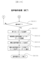
- 3 is a flowchart used to explain an example of voice operation processing.
- FIG. 3 is a flowchart used to explain an example of voice operation processing.
- 3 is a flowchart used to explain an example of voice operation processing.
- FIG. 3 is a diagram used to explain an example of data input/output between a head-mounted display and an information terminal during voice operation.
- FIG. 7 is a block diagram used to explain an example of the configuration of an audio augmented reality object playback device according to a second embodiment.
- mapping technology according to the present invention can contribute to "9. Create a foundation for industry and technological innovation" of the Sustainable Development Goals (SDGs) advocated by the United Nations.
- SDGs Sustainable Development Goals
- FIG. 1 is a block diagram used to explain an example of the configuration of an HMD.
- the HMD 101 can map an object on the virtual space and generate an icon of the mapped object. The user can then select the generated icon and operate the mapped object.
- the HMD 101 includes a control unit 10, a ROM 11, a RAM 12, a storage unit 13, a camera 14, a display 15, a microphone 16, a speaker 17, a button 18, and a touch sensor 19. , is provided.
- the control unit 10 controls the entire HMD 101 according to a predetermined operation program.
- the control unit 10 sends and receives various commands and data to and from each component block in the HMD 101 via a system bus that is a data communication path.
- the control unit 10 may be a main body that executes predetermined processing, and is configured by, for example, a CPU (Central Processing Unit), but may also be configured by using a semiconductor device such as a GPU (Graphics Processing Unit).
- the ROM 11 is constituted by a suitable storage device such as a flash ROM, and stores data such as programs related to the operation of the HMD 101 and processes to be executed.
- the RAM 12 is a memory used when the control unit 10 executes predetermined processing.
- the storage unit 13 can be configured from an appropriate storage device such as a hard disk drive (HDD), and can store data.
- HDD hard disk drive
- the camera 14 is provided at an appropriate position so that it can capture external images.
- the camera 14 may be provided, for example, to be able to obtain information outside the user's field of view.
- the display 15 (display unit) is provided on the front side and displays images. For example, an image acquired by the camera 14 may be displayed on the display 15, and a user wearing the HMD 101 can visually obtain information by viewing the image acquired by the camera 14 displayed on the display 15. Good too. Further, as will be described in detail later, the display 15 can display icons generated by performing mapping processing, but the display 15 also displays other information (for example, information regarding the output volume from the HMD 101, (information acquired from the outside through wireless communication, etc.) may be displayed as appropriate.
- the display 15 can have an appropriate structure.
- the display 15 may be of a non-transmissive type or a transmissive type, for example.
- the HMD 101 may have a structure in which one display 15 is placed in front of each of the user's eyes, or may have a structure in which one display 15 is placed to cover both eyes of the user. good.
- the microphone 16 is a voice input device, and in this embodiment, it is provided at an appropriate position so that the voice of the user wearing the HMD 101 can be input.
- the microphone 16 may be provided, for example, via a member that extends to the mouth.
- the speaker 17 is an audio output device and outputs information through audio.
- the speaker 17 is provided at an appropriate position so that the user can hear the output audio.
- an audio output device different from the speaker 17 may be used; for example, headphones may be provided as the audio output device.
- the HMD 101 may be configured so that the user can perform various operations such as adjusting the volume and image quality and setting communication using the buttons 18 and the touch sensor 19.
- the desired operation content may be achieved by pressing the button 18 corresponding to the user's desired operation, and the position and number of the buttons 18 can be set as appropriate.
- the touch sensor 19 is provided as appropriate so that it can detect a user's operation of pressing an icon or the like displayed on the display 15.
- the HMD 101 includes a voice recognition section 20.
- the speech recognition unit 20 is configured to include a circuit used for speech recognition processing.
- programs and data used for speech recognition are placed in an appropriate storage device such as the ROM 11 or the storage section 13.
- an appropriate storage device such as the ROM 11 or the storage section 13.
- processing of the speech recognition unit 20 a known method may be used, and for example, processing may be performed in which input speech is analyzed and recognized using an acoustic model or a language model.
- the HMD 101 includes an audio input section 21.
- the audio input unit 21 is configured, for example, as an audio input device into which audio output from the information terminal 102 is input in mapping processing to be described later.
- the voice input unit 21 is, for example, a voice input device that can acquire information on the direction to the source of the voice, and as will be described in detail later, the voice input unit 21 is a voice input device that can obtain information on the direction to the source of the voice. Can be configured.
- the HMD 101 includes a distance measuring section 24.
- the distance measurement unit 24 can be configured, for example, by a sensor that measures the distance to the information terminal 102 in a mapping process that will be described later.
- the distance measurement unit 24 includes, for example, a distance measurement camera 25 (for example, a stereo camera), a LiDAR 26, a distance sensor 27 that is a different sensor from these, and can appropriately measure the distance to the information terminal 102. can do.
- the distance measuring section 24 may be configured with one or more sensors. Further, the distance measuring section 24 may be configured with one or more types of sensors.
- the HMD 101 includes a head tracking section 28.
- the head tracking unit 28 is used to detect the inclination of the user's head when the HMD 101 is worn.
- the head tracking unit 28 can be configured with sensors such as an acceleration sensor 29 and a gyro sensor 30, for example.
- the head tracking section 28 may be composed of one or more sensors. Further, the head tracking section 28 may be configured with one or more types of sensors.
- the HMD 101 includes an eye tracking section 31.
- the eye tracking unit 31 is used to detect the direction of the user's line of sight when the HMD 101 is worn.
- the eye tracking unit 31 can be configured with a sensor such as a line of sight detection sensor 32, for example.
- the eye tracking section 31 may include one or more sensors. Further, the eye tracking section 31 may be configured with one or more types of sensors.
- the HMD 101 includes a communication processing section 33.
- the communication processing unit 33 is configured to include a circuit that performs communication processing (for example, signal processing) in wireless communication, and in this embodiment, the HMD 101 is a wireless LAN that performs communication processing when communicating by wireless LAN. It includes a communication unit 34 and a close proximity wireless communication unit 35 that performs communication processing when performing close proximity wireless communication.
- the HMD 101 includes an interface 36 used for communication.
- the HMD 101 can transmit and receive data to and from the outside by performing wireless communication with the outside through the interface 36.
- the HMD 101 may include an antenna 37 used for wireless communication.
- a device used for wireless communication such as a wireless adapter may be provided.
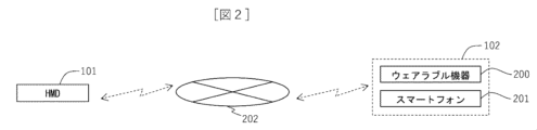
- the HMD 101 can communicate with the information terminal 102 via the network 202, as an example.
- the information terminal 102 is a device that can output audio
- examples of the information terminal 102 include the wearable device 200 and the smartphone 201.
- the HMD 101 has a structure having a glasses shape, but the structure of the HMD 101 is not limited to this example, and can be modified as appropriate.
- the description will be made with reference to the front, back, right, left, and top and bottom directions shown in FIG. 3.
- the HMD 101 includes a front frame part 51 on the front side (front side), a left frame part 52, and a right frame part 53.
- Two displays 15 are attached to the front frame portion 51 so as to be positioned in front of the user's left eye and right eye when worn.
- the left frame portion 52 extends rearward from the left end portion 51a of the front frame portion 51, and is located on the left side of the user's head when worn.
- a speaker 17 (not shown in FIG. 3) is attached to the left frame portion 52 so as to output audio toward the user's left ear.
- the right frame portion 53 extends rearward from the right end portion 51b of the front frame portion 51, and is located on the right side of the user's head when worn.
- a speaker 17 (not shown in FIG. 3) is attached to the right frame portion 53 so as to output sound toward the user's right ear.
- the HMD 101 is provided with a first microphone 22a, a second microphone 22b, and a third microphone 22c, which are microphones that constitute the array microphone 22.
- the first microphone 22a and the second microphone 22b are arranged at the left end 51a and right end 51b of the front frame 51. That is, the first microphone 22a is arranged at the lower right end of the front frame part 51, and the second microphone 22b is arranged at the upper left end of the front frame part 51.
- the third microphone 22c is arranged outside (on the right side) of the right frame portion 53. Note that, contrary to the arrangement shown in FIG.
- the first microphone 22a is arranged at the lower left end of the front frame part 51
- the second microphone 22b is arranged at the upper right end of the front frame part 51
- the microphone 22c may be placed outside (on the left side) of the left frame portion 52.
- the first microphone 22a and the second microphone 22b may be located on the front side of the HMD 101 at the end of the front frame portion 51, or may be located on the left and right sides.
- the direction of the sound source is determined based on the difference in the timing of input to the first microphone 22a and second microphone 22b. (directions related to the horizontal and vertical directions) are specified. Further, when audio is input by the first microphone 22a and the third microphone 22c, the direction of the sound source (with respect to the front-back direction) is determined based on the difference in the timing of input to the first microphone 22a and the third microphone 22c. direction) is specified. Therefore, with the array microphone 22 arranged in this way, the HMD 101 can easily specify the direction of the sound source.
- the array microphone 22 is arranged so that the distance between the first microphone 22a and the second microphone 22b and the distance between the first microphone 22a and the third microphone 22c are approximately the same. It is preferable that each microphone (22a, 22b, 22c) is arranged. With such a structure of positional relationship, it is possible to improve the accuracy of identifying the direction of the sound source.
- the HMD 101 has a structure having a glasses shape, but is not limited to this structure.
- the description will be made with reference to the front, back, left, right, and up and down directions shown in FIG. 4.
- the HMD 101 includes a front frame section 51 on the front side (front side), a left frame section 52, and a right frame section 53.
- a display 15 is attached to the left frame portion 52 and a right frame portion 53, and a speaker 17 (not shown in FIG. 4) is attached to the left frame portion 52 and the right frame portion 53.
- the directional microphone 23 is arranged on the upper end side of the center portion 51c of the front frame portion 51. Then, by using the directional microphone 23, the direction of the sound source is specified. Note that it is only necessary to be able to specify the direction of the sound source, and the directional pattern of the microphone may be set appropriately. Further, in this example, the directional microphone 23 is arranged at the upper end side of the central part 51c of the front frame part 51, but the directional microphone 23 may be arranged at another position. Further, the number of directional microphones 23 may be provided in plurality instead of one, but the number of microphones can be reduced by appropriately switching the directional pattern of the microphones, for example.
- the HMD 101 may have the following structure.
- the HMD 101 is provided with both an array microphone 22 and a directional microphone 23, and the HMD 101 identifies the direction of the sound source based on audio data input to both the array microphone 22 and the directional microphone 23. It's okay.
- the HMD 101 may be provided with a position adjustment mechanism that adjusts the position of the microphone.
- the position adjustment mechanism may be a mechanism that can adjust the position of the microphone by sliding the microphone along the frame.
- the HMD 101 may have a structure that can be folded or unfolded between frames.
- the mapping target is the information terminal 102 (specifically, the wearable device 200, which is an example of the information terminal 102).
- the information terminal 102 is capable of voice input and voice output, and transitions to a mapping mode (mapping mode) by recognizing the input voice.
- the user wearing the HMD 101 inputs a voice to start mapping into the microphone 16 of the HMD 101 and the wearable device 200, thereby causing the HMD 101 and the wearable device 200 to Command to start mapping.
- a voice by emitting, for example, a voice that is a command to start mapping, such as "start mapping”
- HMD 101 and wearable device 200 transition to mapping mode based on appropriate voice recognition.
- the respective information devices may be transitioned to the mapping mode at different timings.
- the user may transition the information terminal 102 to the mapping mode after transitioning the HMD 101 to the mapping mode.
- the user moves the wearable device 200 to the desired registration position and causes the wearable device 200 to output audio.
- the user causes the wearable device 200 to output audio using an appropriate method (for example, key operation, screen touch, voice input to the wearable device 200).
- the audio from the information terminal 102 is input to the HMD 101 (specifically, the audio input section 21 of the HMD 101), so the HMD 101 creates a virtual image of the information terminal 102 based on the input audio. Performs the process of mapping to space.
- the HMD 101 identifies the direction of the sound source (that is, the information terminal 102) based on the sound input to the sound input unit 21, and calculates the distance to the sound source. Note that the distance to the sound source may be calculated as appropriate using audio data input to the audio input unit 21 (for example, data associating the loudness of the input audio with the distance to the sound source).
- the HMD 101 when the HMD 101 includes the distance measuring section 24, the measurement result of the distance to the information terminal 102 by the distance measuring section 24 may be used. By using the measurement results of the distance measuring unit 24, the accuracy of mapping (particularly the accuracy in the depth direction toward the information terminal 102) can be improved. Furthermore, the HMD 101 may detect the position of the information terminal 102 through wireless communication with the information terminal 102, and perform mapping using the result.
- the HMD 101 maps the target information terminal 102 (in this example, the wearable device 200) to a corresponding position in the virtual space based on the direction of the sound source and the distance to the sound source, and Place 103.
- the information terminal 102 is the target of mapping, but the application held by the information terminal 102 may be the target of mapping.
- the application mapping process is performed by causing the information terminal 102 that owns the target application to output audio when starting or using the target application.
- the HMD 101 can generate an icon indicating the mapped object and display the generated icon on the display 15.
- the HMD 101 may display an icon at an appropriate position on the display 15, but as an example, the HMD 101 may display an icon of the target at a position corresponding to the position of the target mapped on the virtual space.
- the HMD 101 may display information related to the name indicating the target (for example, text information indicating "wearable device" when the target is the wearable device 200) attached to the icon.
- the user can hear the audio from the information terminal 102 (in this example, the wearable device 200) and the audio from the speaker 17 of the HMD 101.
- the speaker 17 of the HMD 101 (the left and right speakers 17a and 17b in FIG. 8) is located at a position that is considered to be the same as the information terminal 102 (that is, the location is determined based on the direction of the information terminal 102 and the distance to the information terminal 102).
- the virtual sound source 103 is outputted from the virtual sound source 103. Therefore, the same sound as the sound heard from the information terminal 102 (that is, the sound heard from the position of the virtual sound source 103) is output from the speaker 17 of the HMD 101. Therefore, by comparing the audio actually heard from the information terminal 102 and the audio output from the speaker 17, the user can easily check whether the mapping has been performed appropriately.
- the HMD 101 outputs the sound that can be heard from the position of the virtual sound source 103.
- the relationship between the virtual sound source 103 and stereophonic sound in the virtual space 300 which is the space in which the target is mapped, will be explained.
- Three-dimensional sound is played back so that you can feel the direction and distance of the sound, and in this embodiment, the HMD 101 places a virtual sound source 103 in the virtual space 300, and displays whether the sound emitted from the virtual sound source 103 reaches your ears.
- Three-dimensional sound is expressed by calculating the
- the HMD 101 maps the object to the virtual space 300, which is a coordinate space centered on the position of the user (in the figure, the operator 100 wearing the HMD 101), and Virtual sound sources (103a, 103b) are placed at the mapped positions in space.
- the HMD 101 expresses stereophonic sound by outputting appropriate sounds based on the direction and distance of the virtual sound sources (103a, 103b).
- the HMD 101 can adjust the audio according to the audio output device, and can output the adjusted audio. For example, when the audio output device is the speaker 17, the HMD 101 can output audio adjusted to match the speaker 17. For example, when the audio output device is headphones, the HMD 101 can output audio adjusted to fit the headphones.
- the HMD 101 can map an object to the virtual space 300 of a coordinate system (local coordinate system or world coordinate system) selected by the user.
- a coordinate system local coordinate system or world coordinate system
- FIGS. 11 and 12 the position of the virtual sound source in each coordinate system when the user moves will be described.
- the local coordinate system is a coordinate system in which the position of the virtual sound source (103a, 103b) moves with the user (in the figure, the operator 100). , 103b) moves.
- the positions of the mapped virtual sound sources (103a, 103b) change to follow the user's changed direction.
- a virtual sound source 103c is placed in the virtual space 300
- a virtual sound source 103d is placed in the virtual space 300.
- the virtual sound source ( 103a, 103b) move.
- head tracking may be used in this process, for example.
- the HMD 101 may be provided with a GPS reception sensor, and data based on GPS may be used.
- the world coordinate system is a coordinate system in which the position of the virtual sound source (103a, 103b) is fixed, and in the world coordinate system, even if the user moves, the position of the virtual sound source (103a, 103b) is fixed. The position remains unchanged. Therefore, as shown in FIG. 12, for example, when the user (operator 100 in the figure) changes direction, the direction of the virtual sound source (103a, 103b) with respect to the user changes accordingly.
- the HMD 101 outputs audio from virtual sound sources (103a, 103b) in different directions before and after the user changes direction. Therefore, unlike the local coordinate system, in the world coordinate system, when the user turns or moves, the direction of the sound heard and the sense of distance of the voice change.
- the HMD 101 waits until the user gives a signal to start mapping (S101). Then, when the user utters a voice that signals the start of mapping (for example, the user utters "start mapping") (S102), the control unit 10 performs voice recognition and recognizes the keyword that signals the start of mapping. (S103). Then, the HMD 101 (specifically, the control unit 10) activates a mapping mode, which is a mode in which the keyword is recognized by voice recognition and a target is mapped (S104). Here, the HMD 101 outputs a notification sound to select whether to perform mapping in the local coordinate system or mapping in the world coordinate system (S105).
- a mapping mode which is a mode in which the keyword is recognized by voice recognition and a target is mapped
- the user utters the voice of the keyword selected for mapping in which coordinate system (for example, the user utters "local coordinate system") (S106), and the control unit 10 performs voice recognition. is performed to recognize a keyword indicating which coordinate system to use (S107).
- the HMD 101 outputs a sound that notifies the user that the mapping mode in the selected coordinate system has been activated (S108).
- the HMD 101 outputs, for example, a voice saying "Mapping mode will start in the local coordinate system.”
- data such as keywords used by the HMD 101 for voice recognition in S101 to S108 described above may be stored in an appropriate storage device such as the storage unit 13 in advance.
- the user makes a sound to signal the information terminal 102 (in this example, the wearable device 200) to start mapping (S109). For example, the user utters "registration start”.
- the wearable device 200 recognizes the keyword by voice recognition (S110), and activates the device registration mode which is the mapping mode (S111).
- the wearable device 200 may output a sound notifying that the device registration mode has been activated (S112). For example, wearable device 200 may output a voice saying "Starting device registration mode.”
- data such as keywords used by the information terminal 102 for voice recognition in S109 to S112 may be stored in advance in an appropriate storage device of the information terminal 102.
- the HMD 101 and the information terminal 102 are set to the mapping mode individually, but the user can switch the HMD 101 and the information terminal 102 by inputting audio to the HMD 101 and the information terminal 102 at the same timing. You may also make a transition to mapping mode at the same time.
- mapping is then performed by the process described below.
- the user moves the wearable device 200 to the position desired to be mapped (S201). Then, the user presses a button on the wearable device 200 to output the sound to be mapped (position detection sound) (S202).
- the target to be mapped is the information terminal 102 (in this example, the wearable device 200)
- the user outputs audio related to the mapping mode of the information terminal 102, as an example.
- the target to be mapped is an application owned by the information terminal 102
- the user operates the information terminal 102 to execute the target application and causes the information terminal 102 to output the audio of the application.
- the method for causing the information terminal 102 (in this example, the wearable device 200) to output audio may be any method as long as it can output audio appropriately, and is not limited to the method of pressing a button, but may also be a method of key operation, screen touch, or voice input. A method such as this may be used.
- the HMD 101 captures the audio (position detection sound) via the audio input unit 21 (S203).
- the audio input unit 21 is the array microphone 22, but it may be replaced with the directional microphone 23, for example.
- the control unit 10 calculates the position (distance and direction) of the wearable device 200 from the captured audio (position detection sound) (S204).
- the control unit 10 stores the calculated position information in a memory (in this example, the storage unit 13) (S205).
- the control unit 10 maps the target (in this example, the wearable device 200) to the calculated position on the three-dimensional sound space (on the virtual space 300) (S206).
- the control unit 10 maps the object on the virtual space 300 based on the coordinate system voice recognized in S107 described above.
- the virtual sound source 103 is set on the virtual space 300.
- control unit 10 After mapping onto the virtual space 300, the control unit 10 outputs the sound from the speaker 17 so that the sound is output from the mapped position (that is, the virtual sound source 103) (S207). Therefore, by comparing the audio output from the wearable device 200 and the audio output from the speaker 17, the user can check whether the target has been properly mapped.
- control unit 10 determines whether the mapping is appropriate based on whether the position of the virtual sound source 103 placed in the virtual space 300 by mapping matches the position of the information terminal 102. Good too. Then, the control unit 10 may automatically adjust the mapped position according to the result. That is, the control unit 10 may determine whether the direction of the information terminal 102 and the direction of the virtual sound source 103 match, and adjust the position of the virtual sound source 103 according to the result (S208). Specifically, the control unit 10 determines the consistency of the directions of the voices based on whether the deviation in the directions of the voices is within a predetermined threshold. Then, when the control unit 10 determines that the directions of the sounds do not match, the control unit 10 adjusts the position information of the wearable device 200. The control unit 10 adjusts the position of the virtual sound source 103 by storing the adjusted position information in the memory (S205) and performing mapping again based on this position information (S206).
- the user confirms the consistency of the audio directions of the information terminal 102 and the virtual sound source 103, and presses a button on the wearable device 200 to stop audio output (S209).
- the user may stop the audio output of the wearable device 200 by an appropriate method other than pressing a button.
- mapping process ends through the process described below.
- the user checks whether there is any other target to be mapped, and if there is another target to be mapped, the user maps that target by the method described above (S301). Then, when the user confirms that there is no object to be mapped, he/she utters a voice that signals the end of mapping (S302). Here, the user utters "mapping finished" as an example. Then, the control unit 10 performs voice recognition to recognize a keyword that signals the end of mapping (S303), and ends the mapping mode (S304). Then, the HMD 101 outputs audio notifying the user that the mapping mode has ended (S305). Here, the HMD 101 outputs, for example, a voice saying "mapping mode is ending.”
- mapping process ends from S301 to S305 (S306).
- data such as keywords used by the HMD 101 for speech recognition in S301 to S305 may be stored in advance in an appropriate storage device such as the storage unit 13.
- the HMD 101 may output an audio warning when attempting to perform mapping to a position that has already been mapped on the virtual space 300.
- the HMD 101 may output a voice suggesting in which direction the position of the mapping target should be shifted.
- the HMD 101 can recognize a keyword from the voice input by the user using voice recognition, and shift the position of the mapping target in a predetermined direction.
- the keywords for example, "left", "right”, etc.
- the amount of deviation can be set as appropriate, but as an example, it can be set to the minimum amount that avoids overlapping.
- the control unit 10 may determine the consistency of the direction of the audio regarding S208 described above, after adding this amount of deviation.
- the HMD 101 can generate an icon indicating the mapped object.
- the HMD 101 specifically, the control unit 10) generates an icon will be described.
- the HMD 101 can use the audio output from the information terminal 102 to generate the target icon. That is, data such as a keyword indicating the target and the voice output when the target is activated is stored in advance in the storage device as data for performing voice recognition. Then, the HMD 101 performs voice recognition based on the voice input from the information terminal 102 in S202 and the like described above, and determines a target for generating an icon.
- the target is the wearable device 200 which is the information terminal 102
- the sound output when the wearable device 200 is started in the mapping mode is set as a keyword, and the HMD 101 recognizes this sound. , it may be determined that the target for generating the icon is the wearable device 200.
- the HMD 101 generates an icon for the determined target.
- data such as the design of the icon and the name of the icon may be stored in the storage device, and the control unit 10 can generate an icon corresponding to the determined object based on this data. Further, as will be described in detail later, the control unit 10 can display the generated icon on the display 15. At this time, a name indicating the object may be attached and displayed.
- the target is an app related to weather forecasts
- sounds that are keywords related to weather forecasts for example, "weather, sunny, cloudy, rainy", etc.
- sounds that are output when the app is started, etc. may be stored in the storage device.
- the HMD 101 performs voice recognition based on the voice of the application input from the information terminal 102 in S202 and the like, and determines the target for generating an icon.
- the HMD 101 may acquire information for determining the target by performing communication.
- the HMD 101 may acquire data for identifying a target (for example, information regarding the name of the target) through communication with the information terminal 102, and may determine the target using the acquired information.
- information associated with the information acquired through communication for example, a table with records of information that can be acquired through communication and the name of the target
- the HMD 101 stores this stored information.
- the target may be determined.
- the HMD 101 can display the generated target icon on the display 15.
- the control unit 10 may display an icon at a position corresponding to the mapped position on the virtual space 300 with respect to the user wearing the wearer.
- the display position of the icon can be moved as appropriate by a user's operation or the like.
- the HMD 101 may be configured to be able to move icons, for example, by a user's operation of selecting and moving a displayed icon (by drag and drop).
- the icon may be moved by voice input.
- the target icon displayed on the display 15 can be selected by the user. The user can then appropriately select the target icon and operate the mapped target.
- voice operation processing using icons will be described with reference to flowcharts shown in FIGS. 16 to 18.
- 16 to 18 are flowcharts used to explain an example of voice operation processing.
- the HMD 101 waits until there is a signal from the user to start the voice operation mode (a mode in which voice operation is possible) (S401). Then, when the user utters a voice that signals the start of the voice operation mode (for example, the user utters "start operation") (S402), the control unit 10 performs voice recognition to initiate the voice operation mode. The keyword to signal is recognized (S403). Then, the HMD 101 (specifically, the control unit 10) recognizes the keyword through voice recognition and activates the voice operation mode (S404). Here, the HMD 101 outputs a sound notifying that the voice operation mode has been activated (S405). For example, the HMD 101 notifies the user that "the operation will start”.
- mapping icon an icon generated by mapping
- the user vocalizes the mapping icon of the object he/she wishes to operate (S406).
- the user wants to select the smartphone 201 that is the mapped information terminal 102
- the user speaks "smartphone”.
- the control unit 10 recognizes the mapping icon uttered by the user through voice recognition (S407). That is, the control unit 10 selects the target mapping icon corresponding to the voice input by the user.
- the smartphone is an abbreviation for the smartphone 201.
- the HMD 101 notifies the user of the selected mapping icon by voice (S408).
- the HMD 101 provides a notification that "smartphone has been selected", for example.
- the user checks whether the selected mapping icon is correct based on the content of the notification, and if it is correct, utters that it is correct (for example, utters "OK") (S409). Thereby, the HMD 101 recognizes the keyword through voice recognition, and becomes able to execute the process of S501 described below.
- the mapping icon is not selected correctly, the user vocalizes that it is incorrect (for example, vocalizes "NO"). Then, the user speaks the mapping icon that he/she wishes to operate once again, and causes the HMD 101 to perform a process of recognizing the mapping icon.
- mapping icon that the user wants to operate by voice is selected.
- a sound indicating that the mapping icon has been selected may be output. This sound may be, for example, a simple sound such as "pop", or may be the name of the object indicated by the mapping icon. This allows the user to understand that the mapping icon has been selected.
- the audio indicating that the mapping icon has been selected may be output from the speaker 17 so as to be heard from the direction in which the selected mapping icon is displayed.
- a selected mapping icon is displayed in front of the right eye of the user wearing the HMD 101 with reference to the central part on the front side, a sound that can be heard from the right side may be output.
- audio that sounds like it is coming from the front may be output.
- the HMD 101 may use an appropriate tracking technology in selecting the mapping icon. For example, in addition to the user's voice input to the microphone 16, the HMD 101 detects the direction of the user's head using the head tracking unit 28, and selects a mapping icon for the voice input to the microphone 16 displayed in that direction. You can. In this case, the user's desired mapping icon is selected by turning his or her head in the direction of the mapping icon that the user wishes to select and uttering a voice.
- the HMD 101 detects the user's gaze direction using the eye tracking unit 31, and selects a mapping icon of the voice input to the microphone 16 displayed in that direction. You may. In this case, the user's desired mapping icon is selected by directing the user's line of sight to the mapping icon that the user wants to select and uttering a voice.
- mapping icon that includes not only the voice but also the user's movements and line of sight.
- data such as keywords used for voice recognition may be stored in advance in an appropriate storage device such as the storage unit 13.
- voice operation processing will be explained. This voice operation is performed via wireless communication with the information terminal 102 that performs processing based on voice input from the HMD 101 side.
- the user vocalizes the operation content of the selected target mapping icon (S501).
- operation contents include display-related operations (menu display, menu item selection, etc.), cursor display and movement, volume adjustment, and a call function (a function to process audio during a call) when the target is the smartphone 201, etc.
- Examples include operations related to outgoing and incoming calls, moving the position of a displayed icon (remapping), operating the target information terminal 102, and executing the target application (starting the application).
- the HMD 101 can output audio from the target via the speaker 17 based on a virtual sound source in the virtual space 300.
- the information terminal 102 has a telephone call function
- the information terminal 102 may process audio related to the call, and the microphone 16 and speaker 17 of the HMD 101 may input and output the audio during the call.
- control unit 10 recognizes the operation content by voice recognition (S502), and the HMD 101 notifies the recognized operation content by voice (S503).
- the HMD 101 recognizes that the mapping icon is to be moved to the left through voice recognition, and notifies the user by voice, for example, "Move the smartphone to the left.”
- the operation details are input to the HMD 101, and the HMD 101 recognizes the operation details.
- control unit 10 executes the operation according to the input operation details (S504), and notifies the executed operation details by voice (S505).
- the control unit 10 executes an operation of moving the mapping icon of the smartphone 201 to the left
- the control unit 10 notifies the user by voice, for example, "The smartphone has been moved to the left.”
- the operation of the control unit 10 here is a process before confirmation, and the user determines whether the operation content is correct (S506). If the user determines that the operation content is correct, the process described below is executed and the operation content is determined. On the other hand, if the user determines that the operation details are incorrect, the user inputs the operation details again. Note that in this case, the operation content determined by the user to be incorrect is reset. In this way, in S504 to S506, the operation details input by the control unit 10 are executed. Next, the process of determining the operation details will be explained.
- the control unit 10 If the user determines that the operation content is correct, he/she inputs a keyword indicating that fact by voice (S507). For example, the user utters "OK”. Then, the control unit 10 recognizes the keyword through voice recognition (S508), and determines the content of the operation (S509). Then, the control unit 10 notifies the user by voice that the operation details have been finalized (S510). As described above, when it is determined that the mapping icon of the smartphone 201 has been moved to the left, the control unit 10 may, for example, notify the mapping icon by voice, "I confirm the movement to the left.”
- the voice operation is confirmed in S507 to S510.
- data such as keywords used for voice recognition may be appropriately stored in a storage device such as the storage unit 13, and the control unit 10 stores this data in voice recognition. can be used.
- the HMD 101 may output a voice warning. Then, the HMD 101 may output a voice suggesting in which direction the mapping icons to be moved should be shifted so that the mapping icons do not overlap. Then, the HMD 101 can recognize a keyword from the voice input by the user using voice recognition, and shift the position of the mapping target in a predetermined direction.
- the keywords for example, "left", "right”, etc.
- the amount of deviation can be set as appropriate, but as an example, it can be set to the minimum amount that avoids overlapping.
- the user checks whether there is a mapping icon that he or she wants to perform voice operation on (S601), and if there is no corresponding mapping icon, he or she speaks a keyword to end the voice operation (S602). For example, the user utters "operation completed”. Then, the control unit 10 recognizes the keyword by voice recognition (S603), and the HMD 101 ends the voice operation mode (S604). Then, the HMD 101 notifies the user by voice that the voice mode has ended (S605). Here, the HMD 101 outputs, for example, a voice saying "Operation ends.”
- the voice operation mode ends after going through S601 to S605 (S606).
- data such as keywords used for speech recognition by the HMD 101 in S601 to S605 may be stored in advance in an appropriate storage device such as the storage unit 13.
- the user can perform voice operations on the information terminal 102 from the HMD 101 side.
- data input/output between the HMD 101 and the information terminal 102 during voice operation will be described with reference to FIG. 19.
- the HMD 101 waits until there is a voice input from the user regarding the operation content, and when there is a voice input regarding the operation content, it starts the operation mode for the information terminal 102 (wearable device operation mode in FIG. 19) (S701). ).
- the control unit 10 controls the communication unit (the communication processing unit 33 and the interface 36). and starts communication with the information terminal 102 (in this example, the wearable device 200) (S702).
- the control unit 10 transmits the operation details to the wearable device 200 via the network 202 (S703), and receives the operation result from the wearable device 200 (S704). Then, the user checks the received operation result and confirms whether the operation was performed correctly (S705). That is, in S705, the confirmation in S506 described above is performed. Then, when the user confirms that the correct operation has been performed, a keyword to that effect is input by voice by the user. Then, when the control unit 10 confirms the operation details, the operation mode for the information terminal 102 ends (S706).
- an information terminal system is realized that includes the HMD 101, which is an example of an audio augmented reality object reproduction device, and one or more information terminals 102.
- the wearable device 200 or the smartphone 201 is used as an example of the information terminal 102, but the information terminal 102 may be a different type of terminal.
- the information terminal 102 may be a terminal that can be operated normally using methods other than voice. In this case, input to the information terminal 102 to signal the start of mapping may be performed by a method other than voice.
- FIG. 20 Functions similar to those in other embodiments may be denoted by the same reference numerals, and description thereof may be omitted.
- an example of an audio augmented reality object reproduction device 1001 in which the display 15 is omitted from the HMD 101 described in the first embodiment will be described.
- processing related to display is omitted.
- the audio augmented reality object reproduction device 1001 can be, for example, a device worn on the head like headphones.
- the audio augmented reality object reproduction device 1001 is connected to the information terminal 102, and performs mapping onto the virtual space 300 in accordance with the audio input from the target in the same manner as described above.
- the audio augmented reality object reproduction device 1001 performs processing corresponding to the user's operation.
- the user can perform various operations such as an operation to reproduce the mapped object, as described above.
- the audio augmented reality object reproducing device 1001 can perform output that can be heard from the position of the virtual sound source 103 on the virtual space 300.
- the HMD 101 and the audio augmented reality object reproduction device 1001 described in the embodiment may be used standalone without being connected to the information terminal 102.
- the HMD 101 and the audio augmented reality object playback device 1001 perform mapping using the audio from the information terminal 102 and perform processing according to the user's operation, as described above. Processing that uses communication with is omitted.
- the HMD 101 and the audio augmented reality object playback device 1001 store in advance data to be played from the mapped object; Based on the data, output is performed so that the sound can be heard from a corresponding position on the virtual space 300.
- the audio augmented reality object playback device (101, 1001) may be configured to be used only standalone, and in this case, the configuration for communicating with the information terminal 102 may be omitted. Further, the information terminal 102 may be a terminal in which the configuration used for communication is omitted.
- each processing example may be independent programs, or a plurality of programs may constitute one application program. Furthermore, the order in which each process is performed may be changed.
- Some or all of the functions of the present invention described above may be realized by hardware, for example, by designing an integrated circuit.
- the functions may be realized in software by having a microprocessor unit, CPU, etc. interpret and execute operating programs for realizing the respective functions.
- the scope of software implementation is not limited, and hardware and software may be used together.
- a part or all of each function may be realized by a server. Note that the server only needs to be able to execute functions in cooperation with other components via communication, and may be, for example, a local server, a cloud server, an edge server, a network service, etc., and its form does not matter. Information such as programs, tables, files, etc.
- each function may be stored in a memory, a recording device such as a hard disk, an SSD (Solid State Drive), or a recording medium such as an IC card, SD card, or DVD. However, it may also be stored in a device on a communication network.
- a recording device such as a hard disk, an SSD (Solid State Drive), or a recording medium such as an IC card, SD card, or DVD.
- a recording medium such as an IC card, SD card, or DVD.
- it may also be stored in a device on a communication network.
- control lines and information lines shown in the figures are those considered necessary for explanation, and do not necessarily show all control lines and information lines on the product. In reality, almost all components may be considered to be interconnected.
- Control unit 11 ROM 12 RAM 13 Storage section 14 Camera 15 Display (display section) 16 Microphone 17 Speaker 18 Button 19 Touch sensor 20 Voice recognition section 21 Voice input section 22 Array microphone 23 Directional microphone 24 Distance measurement section 25 Distance measurement camera 26 LiDAR 27 Distance sensor 28 Head tracking unit 29 Acceleration sensor 30 Gyro sensor 31 Eye tracking unit 32 Line of sight detection sensor 33 Communication processing unit 34 Wireless LAN communication unit 35 Proximity wireless communication unit 36 Interface 37 Wireless antenna 100 Operator (user) 101 HMD (head mounted display) 102 Information terminal 103 Virtual sound source 200 Wearable device 201 Smartphone 202 Network 300 Virtual space 1001 Audio augmented reality object playback device
Landscapes
- Physics & Mathematics (AREA)
- Engineering & Computer Science (AREA)
- Acoustics & Sound (AREA)
- Signal Processing (AREA)
- Health & Medical Sciences (AREA)
- Otolaryngology (AREA)
- User Interface Of Digital Computer (AREA)
Abstract
音声拡張現実オブジェクト再生装置は、仮想空間に対象をマッピングすることができる装置とされている。そして、この音声拡張現実オブジェクト再生装置は、所定の処理を実行するプロセッサを備えている。そして、この音声拡張現実オブジェクト再生装置のプロセッサは、一例として、スマートフォンや適宜のウェアラブル機器などの情報端末から出力されて入力される音声に基づいて、情報端末の位置に対応する仮想空間上の位置に、前記情報端末または前記情報端末のアプリを対象としてマッピングする処理を実行することができる。
Description
本発明は、音声拡張現実オブジェクト再生装置、および、音声拡張現実オブジェクト再生装置を用いた情報端末システムに関する。
従来より、音声拡張現実オブジェクト再生装置の一例であって、ユーザの頭部に装着され、スピーカ等の音声出力装置から立体音響技術に基づく音声を出力し、且つ、眼前の表示画面に様々な情報を表示する音声拡張現実オブジェクト再生装置が知られている。
ここで、特許文献1は、立体音響技術に関する技術を開示する。すなわち、特許文献1は、立体音響信号を生成して再生する立体音響信号再生装置であって、第1の距離で測定された頭部伝達関数に対して方位角に沿ったフーリエ変換を行った後に、ハンケル関数を用いて前記第1の距離から第2の距離への変換処理を行い、さらに前記ハンケル関数の次数を変数とする逆フーリエ変換を行って前記第2の距離における頭部伝達関数を生成する第1の処理部と、入力された音響信号に対して前記第2の距離における頭部伝達関数をフィルタとして適用して前記立体音響信号を生成する第2の処理部と、を備えたことを特徴とする立体音響信号再生装置を開示する。
そして、特許文献1の技術は、水平面上の任意の距離のHRTFを合成する手法を用いる場合であっても、不連続点に起因する品質低下を抑制して、高品質な立体音響の再生が可能になるという効果を奏するとされている。また、特許文献1は、人間の知覚精度が高い水平面において、臨場感の高い立体音響信号再生装置を実現できることを開示する。
その一方で、特許文献2は、音声処理装置を開示する。すなわち、特許文献2は、少なくとも2チャネル以上のマイクロホン素子を持つマイクロホンアレーと、前記マイクロホンアレーからの信号をチャネル毎に複数の周波数帯域に分割する帯域分割部と、前記帯域分割された帯域分割信号から音源方向を推定する音源定位部と、上記推定された音源方向毎に上記帯域分割信号を強調する音源分離部と、上記強調された帯域分割信号と上記推定された音源方向の情報を用いて、該帯域分割信号が複数または単数の音源からの信号であるか判定する音源重複判定部と、上記単数の音源からの帯域分割信号と判断された信号を用いて音源探索を行う音源探索部とを有することを特徴とする音声処理装置を開示する。
特許文献2の技術は、複数の音源が重複しているかどうかを判定し単一の音源が鳴っている帯域分割信号のみを音源定位に用いることで、複数の音源が重複し音源の方向情報が失われた帯域成分を使わない。これにより、特許文献2の技術は、音声や音楽の鳴っている方向を高精度に知ることができるとされている。
ユーザによる音声拡張現実オブジェクト再生装置の使用の態様として、一例として、下記の方法が考えられる。すなわち、ユーザは、仮想オブジェクトとして対象(情報端末やアプリ)を音声拡張現実オブジェクト再生装置の仮想空間にマッピングし、該音声拡張現実オブジェクト再生装置を用いてマッピングした対象の操作を行う。しかしながら、例えば、ユーザの外界に対する視覚が制限される場合などでは、ユーザは容易なマッピングを行えず、ユーザの利便性が欠けるということが考えられる。なお、上記で説明した特許文献1および特許文献2は、このようなマッピング技術を開示しないと考えられる。
そこで、本発明は、ユーザの利便性の向上が図られており、マッピングを容易に行うことができる音声拡張現実オブジェクト再生装置、および、該音声拡張現実オブジェクト再生装置を用いた情報端末システムを提供することを目的とする。
本発明の第1の態様によれば、下記の音声拡張現実オブジェクト再生装置が提供される。音声拡張現実オブジェクト再生装置は、仮想空間に対象をマッピングすることができる。音声拡張現実オブジェクト再生装置は、プロセッサを備える。プロセッサは、情報端末から出力されて入力される音声に基づいて、前記情報端末の位置に対応する仮想空間上の位置に、前記情報端末または前記情報端末のアプリを対象としてマッピングする。
本発明の第2の態様によれば、下記の情報端末システムが提供される。情報端末システムは、1台または複数台の情報端末と、仮想空間に対象をマッピングすることができる音声拡張現実オブジェクト再生装置と、を備える。音声拡張現実オブジェクト再生装置は、プロセッサを備える。プロセッサは、情報端末から出力されて入力される音声に基づいて、前記情報端末の位置に対応する仮想空間上の位置に、前記情報端末または前記情報端末のアプリを対象としてマッピングする。
本発明によれば、ユーザの利便性の向上が図られており、マッピングを容易に行うことができる音声拡張現実オブジェクト再生装置、および、該音声拡張現実オブジェクト再生装置を用いた情報端末システムが提供される。
以下、本発明を実施するための形態について、図面に従い説明する。なお、以降で説明する内容は、本発明を実施するための形態の一つであって、同様の処理が可能な他の構成、形態への適用を制限するものではない。本発明に係るマッピング技術により、国連の提唱する持続可能な開発目標(SDGs:Sustainable Development Goals)の「9.産業と技術革新の基盤をつくろう」に貢献することができる。
先ず、図1を参照しながら、音声拡張現実オブジェクト再生装置の一例として、ヘッドマウントディスプレイ(HMDと記載することがある)の構成の一例について説明する。なお、音声拡張現実オブジェクト再生装置は、対象の音声を用いてマッピングし、マッピングした対象の音声を再生することができる装置である。図1は、HMDの構成の一例の説明に用いるブロック図である。第1実施形態によれば、HMD101は、仮想空間上に対象をマッピングし、マッピングした対象のアイコンを生成することができる。そして、ユーザは、生成したアイコンを選択し、マッピングした対象を操作することができる。
図1に示すように、HMD101は、制御部10と、ROM11と、RAM12と、ストレージ部13と、カメラ14と、ディスプレイ15と、マイク16と、スピーカ17と、ボタン18と、タッチセンサ19と、を備える。
制御部10(プロセッサ)は、所定の動作プログラムに従ってHMD101全体を制御する。制御部10は、データ通信路であるシステムバスを介して、HMD101内の各構成ブロックとの間で各種コマンドやデータなどの送受信を行う。制御部10は、所定の処理を実行する主体であればよく、例えば、CPU(Central Processing Unit)により構成されるが、GPU(Graphics Processing Unit)等の半導体デバイスを用いて構成されてもよい。
ROM11は、フラッシュROMなどの適宜の記憶装置により構成され、HMD101の動作や実行する処理に関するプログラム等のデータを記憶する。RAM12は、制御部10が所定の処理を実行する際に用いられるメモリである。ストレージ部13は、ハードディスクドライブ(HDD:Hard Disk Drive)等の適宜の記憶装置から構成することができ、データを記憶することができる。
カメラ14は、外部の画像を取得することができるように、適宜の位置に設けられる。カメラ14は、例えば、ユーザの視野の範囲外の情報を取得することができるように設けられてもよい。
ディスプレイ15(表示部)は、正面側に設けられ、画像を表示する。ディスプレイ15には、例えば、カメラ14で取得する画像が表示されてもよく、HMD101を装着したユーザは、ディスプレイ15に表示されるカメラ14が取得した画像を見ることで、視覚により情報を得てもよい。また、ディスプレイ15は、後で詳しく説明するように、マッピング処理を行って生成したアイコンを表示することができるが、ディスプレイ15には、これ以外の情報(例えば、HMD101からの出力音量に関する情報、無線通信で外部から取得する情報など)が適宜に表示されてもよい。
なお、ディスプレイ15は、適宜の構造とすることができる。ディスプレイ15は、例えば、非透過型であってもよいし透過型であってもよい。また、HMD101は、例えば、ユーザの両眼それぞれの前に1枚ずつディスプレイ15を配置する構造とされてもよいし、ユーザの両眼を覆う1枚のディスプレイ15を配置する構造とされてもよい。
マイク16は、音声入力装置であり、本実施形態では、HMD101を装着したユーザの声を入力することができるように、適宜の位置に設けられる。マイク16は、例えば、口元まで伸ばす部材を介して設けられてもよい。
スピーカ17は、音声出力装置であり、音声により情報を出力する。スピーカ17は、出力される音声をユーザが聞くことができるように、適宜の位置に設けられる。なお、スピーカ17とは異なる音声出力装置が用いられてもよく、例えば、ヘッドフォンが音声出力装置として設けられてもよい。
HMD101は、ボタン18やタッチセンサ19により、音量や画質の調整、通信の設定などの各種の操作をユーザが行うことができるように構成されてもよい。ユーザの所望の操作に対応するボタン18を押すことで、所望の操作内容が実現されればよく、ボタン18の位置や数は、適宜に設定可能である。タッチセンサ19は、ディスプレイ15に表示されるアイコンなどを押すユーザの操作を検知することができるように、適宜に設けられる。
HMD101は、音声認識部20を備える。音声認識部20は、音声認識の処理に用いる回路などを含んで構成される。ここで、音声認識に用いるプログラムやデータは、ROM11やストレージ部13などの適宜の記憶装置に配置される。なお、音声認識部20の処理では、公知の手法が用いられてもよく、例えば、音響モデルや言語モデルを用いて入力される音声を解析して認識する処理が行われてもよい。
HMD101は、音声入力部21を備える。音声入力部21は、例えば、後述するマッピング処理において、情報端末102から出力される音声が入力される音声入力装置として構成される。音声入力部21は、一例として、音声の発生源への方位の情報を取得することができる音声入力装置とされ、後で詳しく説明するように、例えば、アレイマイク22や指向性マイク23などにより構成することができる。
HMD101は、距離測定部24を備える。距離測定部24は、例えば、後述するマッピング処理において、情報端末102までの距離を測定するセンサにより構成することができる。距離測定部24は、例えば、距離測定カメラ25(一例として、ステレオカメラ)、LiDAR26、これらとは異なるセンサであって情報端末102までの距離を適宜に測定することができる距離センサ27などで構成することができる。なお、距離測定部24は、1又は複数のセンサにより構成されてもよい。また、距離測定部24は、1又は複数の種類のセンサにより構成されてもよい。
HMD101は、ヘッドトラッキング部28を備える。ヘッドトラッキング部28は、HMD101の装着時において、ユーザの頭部の傾きを検出することに用いられる。ヘッドトラッキング部28は、例えば、加速度センサ29やジャイロセンサ30などのセンサで構成することができる。なお、ヘッドトラッキング部28は、1又は複数のセンサにより構成されてもよい。また、ヘッドトラッキング部28は、1又は複数の種類のセンサにより構成されてもよい。
HMD101は、アイトラッキング部31を備える。アイトラッキング部31は、HMD101の装着時において、ユーザの視線方向を検出することに用いられる。アイトラッキング部31は、例えば、視線検出センサ32などのセンサで構成することができる。なお、アイトラッキング部31は、1又は複数のセンサにより構成されてもよい。また、アイトラッキング部31は、1又は複数の種類のセンサにより構成されてもよい。
HMD101は、通信処理部33を備える。通信処理部33は、無線通信において、通信処理(例えば、信号処理)を行う回路などを含んで構成され、本実施形態では、HMD101は、無線LANによる通信を行うときに通信処理を行う無線LAN通信部34と、近接無線通信を行うときに通信処理を行う近接無線通信部35と、を備える。
また、HMD101は、通信に用いるインタフェース36を備える。HMD101は、インタフェース36を介して外部と無線通信を行うことにより、外部とデータの送受信を行うことができる。ここで、HMD101は、無線通信に用いるアンテナ37を備えてもよい。また、無線アダプタなどの無線通信に用いる機器が設けられてもよい。
次に、図2を参照しながら、無線通信の態様の一例について説明する。図2に示すように、HMD101は、一例として、ネットワーク202を介して情報端末102と通信することができる。ここで、本実施形態では、情報端末102は、音声を出力することができる装置であり、情報端末102には、一例として、ウェアラブル機器200やスマートフォン201が挙げられる。
次に、図3を参照しながら、音声入力部21がアレイマイク22により構成されているHMD101の構造の一例について説明する。なお、図3の例では、HMD101は、メガネ形状を有する構造とされているが、HMD101の構造は、この例に限定されず、適宜の変更が可能である。ここで、図3に示す前後左右および上下方向を基準として説明する。
図3に示すように、HMD101は、正面側(前側)の正面フレーム部51と、左フレーム部52と、右フレーム部53と、を備える。正面フレーム部51には、装着時においてユーザの左眼および右眼それぞれの前に位置するように、ディスプレイ15が2枚取り付けられている。
左フレーム部52は、正面フレーム部51の左端部51aから後方側に延びており、装着時においてユーザの左側頭部側に位置する。左フレーム部52には、ユーザの左耳に向けて音声を出力するように、図3に図示されていないスピーカ17が取り付けられている。同様に、右フレーム部53は、正面フレーム部51の右端部51bから後方側に延びており、装着時においてユーザの右側頭部側に位置する。右フレーム部53には、ユーザの右耳に向けて音声を出力するように、図3に図示されていないスピーカ17が取り付けられている。
また、HMD101には、アレイマイク22を構成するマイクである、第1のマイク22a、第2のマイク22b、および、第3のマイク22cが設けられている。図3の例では、第1のマイク22aおよび第2のマイク22bは、正面フレーム51の左端部51aおよび右端部51bに配置されている。すなわち、第1のマイク22aが正面フレーム部51の右下端部に配置され、第2のマイク22bが正面フレーム部51の左上端部に配置されている。また、第3のマイク22cが右フレーム部53の外側(右側)に配置されている。なお、図3に示す配置とは逆に、第1のマイク22aが正面フレーム部51の左下端部に配置され、第2のマイク22bが正面フレーム部51の右上端部に配置され、第3のマイク22cが左フレーム部52の外側(左側)に配置されてもよい。また、第1のマイク22aや第2のマイク22bは、正面フレーム部51の端部において、HMD101の正面側に位置してもよいし、左右側に位置してもよい。
このように配置される第1のマイク22aおよび第2のマイク22bにより、音声が入力された場合、第1のマイク22aおよび第2のマイク22bに入力するタイミングの差分に基づいて、音源の方向(左右方向および上下方向に関する方向)が特定される。また、第1のマイク22aおよび第3のマイク22cにより、音声が入力された場合、第1のマイク22aおよび第3のマイク22cに入力するタイミングの差分に基づいて、音源の方向(前後方向に関する方向)が特定される。従って、このように配置されるアレイマイク22により、HMD101は、音源の方向を容易に特定することができる。
ここで、上記で説明した配置に関して、第1のマイク22aと第2のマイク22bの距離、および、第1のマイク22aと第3のマイク22cの距離が略同一となるように、アレイマイク22の各マイク(22a、22b、22c)が配置されることが好ましい。このような位置関係の構造とすることで、音源の方向を特定する精度の向上を図ることができる。
次に、図4を参照しながら、音声入力部21が指向性マイク23により構成されているHMD101の構造の一例について説明する。図4の例では、図3の場合と同様に、HMD101は、メガネ形状を有する構造とされているが、この構造に限定されない。ここで、図4に示す前後左右および上下方向を基準として説明する。
上記で説明したアレイマイク22の場合の構成と同様に、HMD101は、正面側(前側)の正面フレーム部51と、左フレーム部52と、右フレーム部53と、を備え、正面フレーム部51には、ディスプレイ15が取り付けられており、左フレーム部52および右フレーム部53には、図4に図示されていないスピーカ17が取り付けられている。
図4の例では、指向性マイク23は、正面フレーム部51の中央部51cの上端側に配置されている。そして、指向性マイク23を用いることにより、音源の方向が特定される。なお、音源の方向を特定することができればよく、マイクの指向性パターンは、適宜に設定されればよい。また、この例では、正面フレーム部51の中央部51cの上端側に指向性マイク23が配置されているが、他の位置に指向性マイク23が配置されてもよい。また、指向性マイク23は、単数ではなく複数設けられてもよいが、例えば、マイクの指向性パターンを適切に切り替えることで、マイクの数を減らすことが可能である。
上記では、アレイマイク22を備えるHMD101、および、指向性マイク23を備えるHMD101について説明されたが、HMD101は、下記のような構造とされてもよい。例えば、HMD101には、アレイマイク22と指向性マイク23の両方が設けられ、HMD101は、アレイマイク22および指向性マイク23の両方に入力される音声のデータに基づいて、音源の方向を特定してもよい。また、HMD101には、マイクの位置を調整する位置調整機構が設けられてもよい。位置調整機構は、一例として、マイクをフレームに沿ってスライドさせることで、マイクの位置を調整することができる機構とされてもよい。また、HMD101は、フレームの間で折り畳みまたは展開することができる構造となっていてもよい。
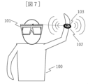
次に、図5から図7を参照しながら、ユーザが対象をマッピングする方法の一例について説明する。図5から図7の例では、マッピングの対象は、情報端末102(詳細には、情報端末102の一例であるウェアラブル機器200)である。そして、この例では、情報端末102は、音声入力および音声出力が可能であり、入力する音声を認識することで、マッピングを行うモード(マッピングモード)に遷移する。
図5に示すように、HMD101を装着したユーザ(図5において、操作者100)は、HMD101のマイク16およびウェアラブル機器200に、マッピングを開始させる音声を入力することで、HMD101およびウェアラブル機器200にマッピング開始を指令する。ユーザが、例えば、「マッピング開始」というマッピング開始の指令となる音声を発して音声を入力することで、HMD101およびウェアラブル機器200は、適宜の音声認識に基づいて、マッピングモードに遷移する。
なお、HMD101と情報端末102を同時にマッピングモードに遷移させる例について説明されたが、それぞれの情報機器(101、102)を異なるタイミングでマッピングモードに遷移させてもよい。ユーザは、例えば、HMD101をマッピングモードに遷移させた後に、情報端末102をマッピングモードに遷移させてもよい。
次に、図6に示すように、ユーザは、ウェアラブル機器200を登録したい位置に移動させ、ウェアラブル機器200に音声を出力させる。ここで、ユーザは、適宜の手法(例えば、ウェアラブル機器200に対する、キー操作、画面タッチ、音声入力)により、ウェアラブル機器200に音声を出力させる。
それから、図7に示すように、情報端末102からの音声がHMD101(詳細には、HMD101の音声入力部21)に入力するので、HMD101は、入力する音声に基づいて、この情報端末102を仮想空間にマッピングする処理を行う。ここで、HMD101は、音声入力部21に入力される音声に基づいて、音源(つまり、情報端末102)の方位を特定し、音源までの距離を算出する。なお、音源までの距離は、音声入力部21に入力される音声のデータ(例えば、入力する音声の大きさと音源までの距離を関連付けたデータ)を用いて適宜に計算されてもよい。また、HMD101が距離測定部24を備える場合、距離測定部24による情報端末102までの距離の測定結果が用いられてもよい。距離計測部24の測定結果を用いることで、マッピングの精度(特に、情報端末102への奥行き方向の精度)の向上が図られる。また、HMD101は、情報端末102との無線通信により、情報端末102の位置検出を行い、その結果を用いてマッピングを行ってもよい。
そして、HMD101は、音源の方位および音源までの距離に基づいて、対象である情報端末102(この例では、ウェアラブル機器200)を仮想空間上の対応する位置にマッピングし、マッピングした対象の仮想音源103を配置する。なお、ここでの説明では、情報端末102がマッピングの対象とされていたが、情報端末102が保有するアプリがマッピングの対象であってもよい。この場合、アプリのマッピング処理は、対象とするアプリを保有する情報端末102に、対象とするアプリの起動時や利用時の音声を出力させて行われる。
そして、HMD101は、マッピングした対象を示すアイコンを生成し、生成したアイコンをディスプレイ15に表示させることができる。ここで、HMD101は、ディスプレイ15の適宜の位置にアイコンを表示させてもよいが、一例として、仮想空間上にマッピングされた対象の位置に対応する位置に、対象のアイコンを表示させることができる。なお、HMD101は、対象を示す名称に関する情報(例えば、対象がウェアラブル機器200である場合に「ウェアラブル機器」とする文字情報)を、アイコンに付して表示させてもよい。
ここで、図8および図9を参照しながら、マッピング時およびマッピング後におけるHMD101の音声出力の一例について説明する。
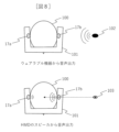
対象のマッピング時において、図8に示すように、ユーザは、情報端末102(この例では、ウェアラブル機器200)からの音声、および、HMD101のスピーカ17からの音声を聞くことができる。ここで、HMD101のスピーカ17(図8において、左右それぞれのスピーカ17a、17b)は、情報端末102と同一と考えられる位置(すなわち、情報端末102の方位および情報端末102までの距離に基づいて求められる位置)を仮想音源103とする音声を出力する。従って、情報端末102から聞こえてくる音声と同様の音声(すなわち、仮想音源103の位置から聞こえてくるような音声)が、HMD101のスピーカ17から出力される。そのため、ユーザは、実際に情報端末102から聞こえてくる音声とスピーカ17から出力される音声を比べることで、マッピングが適切に行われているかどうかについて、容易に確認することができる。
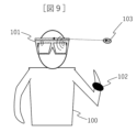
なお、マッピング後では、図9に示すように、情報端末102(この例では、ウェアラブル機器200)の位置を変更しても、HMD101は、仮想音源103の位置から聞こえるような音声を出力する。
ここで、図10を参照しながら、対象をマッピングする空間である仮想空間300における仮想音源103と立体音響の関係について説明する。立体音響は、音の方向や距離感まで感じられるように再生することであり、本実施形態では、HMD101は、仮想空間300に仮想音源103を配置し、そこから発せられる音が耳に届くかどうかを演算することで、立体音響を表現する。
すなわち、上記で説明したようなユーザの操作により、HMD101は、ユーザ(図において、該HMD101を装着した操作者100)の位置を中心とする座標空間である仮想空間300に対象をマッピングし、仮想空間上のマッピングした位置に仮想音源(103a、103b)を配置する。そして、HMD101は、仮想音源(103a、103b)の方向および距離に基づいて、適切な音声の出力を行うことにより、立体音響を表現する。ここで、HMD101は、音声出力装置に合わせて音声を調整することができ、調整した音声を出力することができる。例えば、音声出力装置がスピーカ17である場合、HMD101は、スピーカ17に合わせて調整した音声を出力することができる。例えば、音声出力装置がヘッドフォンである場合、HMD101は、ヘッドフォンに合わせて調整した音声を出力することができる。
また、本実施形態では、HMD101は、ユーザにより選択された座標系(局所座標系または世界座標系)の仮想空間300に対象をマッピングすることができる。ここで、図11および図12を参照しながら、ユーザが移動などした場合における、それぞれの座標系における仮想音源の位置について説明する。
先ず、図11を参照しながら、仮想空間300が局所座標系である場合について説明する。局所座標系は、仮想音源(103a、103b)の位置がユーザ(図において、操作者100)とともに移動する座標系であり、局所座標系の場合、ユーザの動きに対応するように仮想音源(103a、103b)が移動する。
図11に示すように、例えば、HMD101を装着したユーザが向きを変えた場合、マッピングされている仮想音源(103a、103b)の位置が、変更したユーザの向きに追従するように変わる。図11の例では、仮想音源103aの位置が変わることで、仮想空間300上に仮想音源103cが配置され、仮想音源103bの位置が変わることで、仮想空間300上に仮想音源103dが配置される。このように、局所座標系では、ユーザの位置および向き(言い換えれば、HMD101の位置および向き)を基準として、一定の方位および一定の距離の関係を保つように、仮想空間300上で仮想音源(103a、103b)の位置が移動する。なお、この処理にあたって、一例として、ヘッドトラッキングが利用されてもよい。また、一例として、HMD101にGPS受信センサが設けられ、GPSに基づくデータが利用されてもよい。
従って、局所座標系では、HMD101を装着したユーザが向きを変えたり、移動した場合でも、ユーザを基準とした仮想音源の方位および仮想音源までの距離は変わらず、HMD101は、ユーザを基準として一定の方位および一定の距離の関係にある仮想音源からの音声を出力する。
これに対して、世界座標系は、仮想音源(103a、103b)の位置が固定された座標系であり、世界座標系では、ユーザが移動などをした場合でも、仮想音源(103a、103b)の位置は変わらない。従って、図12に示すように、例えば、ユーザ(図において、操作者100)が向きを変えた場合、これに伴って、ユーザを基準とする仮想音源(103a、103b)の方位が変わることになり、HMD101は、ユーザが向きを変える前後において異なる方向の仮想音源(103a、103b)から音声を出力する。そのため、局所座標系とは異なり世界座標系では、ユーザが向きを変えたり移動することで、聞こえてくる音の方向や音声の距離感が変わる。
次に、図13から図15に示すフローチャートを参照しながら、マッピング処理の詳細について説明する。図13から図15は、マッピング処理の一例の説明に用いるフローチャートである。
図13に示すように、HMD101は、ユーザによるマッピング開始の合図があるまで待機する(S101)。そして、ユーザがマッピング開始を合図する音声を発声(例えば、ユーザが「マッピング開始」と発声)することで(S102)、制御部10は、音声認識を行ってマッピング開始を合図するキーワードを認識する(S103)。そして、HMD101(詳細には、制御部10)は、音声認識によりキーワードを認識し、対象をマッピングするモードであるマッピングモードを起動する(S104)。ここで、HMD101は、局所座標系でのマッピングを行うか、または、世界座標系でのマッピングを行うかについて選択する通知の音声を出力する(S105)。そして、ユーザは、何れの座標系でのマッピングを行うかについて選択したキーワードの音声を発声(例えば、ユーザが「局所座標系」と発声)することで(S106)、制御部10は、音声認識を行って何れの座標系を用いるかについてのキーワードを認識する(S107)。そして、HMD101は、選択された座標系でのマッピングモードを起動したことをユーザに通知する音声を出力する(S108)。ここで、HMD101は、例えば、「局所座標系でマッピングモードを開始します」という音声を出力する。
なお、上記したS101からS108においてHMD101が音声認識に用いるキーワードなどのデータは、ストレージ部13などの適宜の記憶装置に予め記憶させておいてもよい。
次に、ユーザは、情報端末102(この例では、ウェアラブル機器200)にマッピング開始を合図する音声を発声する(S109)。ユーザは、例えば、「登録開始」と発声する。ここで、ウェアラブル機器200は、上記で説明したHMD101の場合と同様に、音声認識によりキーワードを認識し(S110)、マッピングモードである機器登録モードを起動する(S111)。ここで、ウェアラブル機器200は、機器登録モードを起動したことを通知する音声を出力してもよい(S112)。ウェアラブル機器200は、例えば、「機器登録モードを開始します」という音声を出力してもよい。
なお、上記した場合と同様に、S109からS112において情報端末102が音声認識に用いるキーワードなどのデータは、情報端末102の適宜の記憶装置に予め記憶させておいてもよい。また、この例では、HMD101と情報端末102を個別にマッピングモードにする例が説明されたが、ユーザは、同じタイミングでHMD101と情報端末102に音声を入力することで、HMD101と情報端末102を同時にマッピングモードに遷移させてもよい。
このように、S101からS112において、マッピング処理の準備が行われる。そして、下記に説明する処理により、マッピングが行われる。
図14に示すように、先ず、ユーザは、マッピングしたい位置にウェアラブル機器200を移動させる(S201)。そして、ユーザは、ウェアラブル機器200のボタンを押下し、マッピングする対象の音声(位置検出音)を出力させる(S202)。
ここで、マッピングする対象を情報端末102(この例では、ウェアラブル機器200)とする場合、ユーザは、一例として、情報端末102のマッピングモードに関する音声を出力させる。その一方で、マッピングする対象を情報端末102が保有するアプリとする場合、ユーザは、情報端末102を操作して対象となるアプリを実行させ、情報端末102にアプリの音声を出力させる。
なお、情報端末102(この例では、ウェアラブル機器200)に音声を出力させる手法は、音声を適切に出力させることができればよく、ボタンの押下の手法に限らず、キー操作、画面タッチ、音声入力などの手法であってもよい。
そして、S202において情報端末102から音声が出力された場合、HMD101は、音声入力部21を介して音声(位置検出音)を取り込む(S203)。ここで、この例では、音声入力部21は、アレイマイク22とされているが、例えば、指向性マイク23に代えてもよい。
そして、制御部10は、取り込んだ音声(位置検出音)から、ウェアラブル機器200の位置(距離および方位)を算出する(S204)。ここで、制御部10は、算出した位置情報をメモリ(この例では、ストレージ部13)に保存する(S205)。そして、制御部10は、立体音空間上(仮想空間300上)の算出した位置に、対象(この例では、ウェアラブル機器200)をマッピングする(S206)。ここで、制御部10は、上記したS107で音声認識した座標系に基づいて、仮想空間300上に対象をマッピングする。これにより、仮想空間300上に仮想音源103が設定される。
制御部10は、仮想空間300上にマッピングした後に、マッピングされた位置(すなわち、仮想音源103)から音声が出力されているように、スピーカ17から音声を出力する(S207)。従って、ユーザは、ウェアラブル機器200から出力される音声と、スピーカ17から出力される音声と、を比べることで、対象を適切にマッピングできたかどうかについて確認することができる。
なお、制御部10は、マッピングにより仮想空間300上に配置される仮想音源103の位置が、情報端末102の位置に一致しているかどうかに基づいて、マッピングが適切であるかどうかについて判定してもよい。そして、制御部10は、その結果に応じて、マッピングした位置の自動調整を行ってもよい。すなわち、制御部10は、情報端末102の方向と仮想音源103の方向が一致しているどうかについて判定し、その結果に応じて仮想音源103の位置を調整してもよい(S208)。具体的に説明すると、制御部10は、音声の方向のズレが所定の閾値以内であるかどうかに基づいて、音声の方向の一致性を判定する。そして、制御部10は、音声の方向が一致していないと判定した場合に、ウェアラブル機器200の位置情報を調整する。制御部10は、調整した位置情報をメモリに保存し(S205)、この位置情報に基づくマッピングを再度行うことで(S206)、仮想音源103の位置を調整する。
そして、ユーザは、情報端末102と仮想音源103の音声の方向の一致性を確認し、ウェアラブル機器200のボタンを押下して音声出力を停止させる(S209)。なお、上記したS202の場合と同様に、ユーザは、ボタンの押下以外の適宜の手法で、ウェアラブル機器200の音声出力を停止させてもよい。
このようにして、S201からS206の処理において、仮想空間300上に対象がマッピングされ、S207からS209の処理において、マッピングが適切であるかどうかについての確認が行われる。そして、下記に説明する処理を経て、マッピング処理が終了する。
図15に示すように、ユーザは、マッピングする対象が他にないかどうか確認し、マッピングする対象が他にある場合、上記で説明した方法により、その対象をマッピングする(S301)。そして、ユーザは、マッピングする対象がないことを確認した場合、マッピング終了を合図する音声を発声する(S302)。ここで、ユーザは、一例として、「マッピング終了」と発声する。そして、制御部10は、音声認識を行ってマッピング終了を合図するキーワードを認識し(S303)、マッピングモードを終了する(S304)。そして、HMD101は、マッピングモードを終了したことをユーザに通知する音声を出力する(S305)。ここで、HMD101は、例えば、「マッピングモードを終了します」という音声を出力する。
このように、S301からS305を経て、マッピング処理が終了する(S306)。なお、S301からS305においてHMD101が音声認識に用いるキーワードなどのデータは、ストレージ部13などの適宜の記憶装置に予め記憶させておいてもよい。
なお、HMD101は、仮想空間300上において、既にマッピング済みの位置にマッピングを行おうとした場合に、音声による警告を出力してもよい。その際、HMD101は、マッピングする対象の位置をどの方向にずらすかについて提案する音声を出力してもよい。そして、HMD101は、音声認識を用いてユーザが入力する音声からキーワードを認識し、所定の方向にマッピングする対象の位置をずらすことができる。ここで、キーワード(例えば、「左」、「右」など)は、適宜の記憶装置に記憶される。また、ずれ量は、適宜に設定することができるが、一例として、重なりを回避する最小の量とすることができる。そして、制御部10は、このずれ量を加えた上で、上記したS208に関する音声の方向の一致性を判定してもよい。
さらに、HMD101は、マッピングした対象を示すアイコンを生成することができる。次に、HMD101(詳細には、制御部10)がアイコンを生成する方法の一例について説明する。
HMD101は、対象のアイコンを生成するにあたって、情報端末102から出力される音声を利用することができる。すなわち、対象を示すキーワードや対象を起動したときに出力される音声などのデータが、音声認識を行うデータとして、記憶装置に予め記憶される。そして、HMD101は、上記したS202などで情報端末102から入力される音声に基づいて音声認識を行い、アイコンを生成する対象を判別する。
ここで、例えば、対象が情報端末102であるウェアラブル機器200である場合、マッピングモードでウェアラブル機器200を起動したときに出力される音声などがキーワードとされ、HMD101は、この音声を認識することで、アイコンを生成する対象がウェアラブル機器200であること判別してもよい。
そして、HMD101は、判別した対象のアイコンを生成する。ここで、アイコンの絵柄やアイコンの名称のなどのデータが記憶装置に記憶されていてもよく、制御部10は、このデータに基づいて、判別した対象に対応するアイコンを生成することができる。また、後で詳しく説明するように、制御部10は、ディスプレイ15に生成したアイコンを表示させることができる。このとき、対象を示す名称が付されて表示されてもよい。
また、対象がアプリである場合のアイコンの生成の一例についても説明する。対象がアプリである場合、情報端末102の例と同様に、アプリを示すキーワードなどのデータが記憶装置に記憶される。
ここで、例えば、対象が天気予報に関するアプリである場合、天気予報に関するキーワード(例えば、「天気、晴れ、曇り、雨」など)となる音声や、アプリを起動させたときに出力される音声などが、記憶装置に記憶されてもよい。そして、HMD101は、S202などで情報端末102から入力されるアプリの音声に基づいて音声認識を行い、アイコンを生成する対象を判別する。
なお、ここでは、音声認識に基づいて、アイコンを生成する対象を判別する例が説明されたが、HMD101は、通信を行うことで、対象を判別する情報を取得してもよい。HMD101は、例えば、情報端末102との通信により、対象を判別するためのデータ(例えば、対象の名称に関する情報)を取得し、取得した情報を利用して対象を判別してもよい。ここで、通信により取得する情報に関連付けた情報(例えば、通信で取得可能な情報と、対象の名称と、をレコードとするテーブル)が記憶装置に記憶され、HMD101は、この記憶された情報を参照することで、通信により取得する情報から対象を判別してもよい。
そして、HMD101は、生成した対象のアイコンをディスプレイ15に表示させることができる。ここで、制御部10は、一例として、装着したユーザを基準として、仮想空間300上のマッピングした位置に対応する位置に、アイコンを表示させてもよい。なお、アイコンの表示位置は、ユーザの操作などにより適宜に移動させることができる。HMD101は、例えば、表示されるアイコンを選択し移動させるユーザの操作により(ドラッグ・アンド・ドロップにより)、アイコンを移動させることができるように構成されてもよい。その一方で、後で詳しく説明するように、音声入力によるアイコンの移動が実行されてもよい。
HMD101において、ディスプレイ15に表示される対象のアイコンは、ユーザにより選択可能とされている。そして、ユーザは、対象のアイコンを適宜に選択し、マッピングした対象を操作することができる。次に、図16から図18に示すフローチャートを参照しながら、アイコンを用いた音声操作処理について説明する。図16から図18は、音声操作処理の一例の説明に用いるフローチャートである。
図16に示すように、HMD101は、ユーザによる音声操作モード(音声操作が可能なモード)の開始の合図があるまで待機する(S401)。そして、ユーザが音声操作モードの開始を合図する音声を発声(例えば、ユーザが「操作開始」と発声)することで(S402)、制御部10は、音声認識を行って音声操作モードの開始を合図するキーワードを認識する(S403)。そして、HMD101(詳細には、制御部10)は、音声認識によりキーワードを認識し、音声操作モードを起動する(S404)。ここで、HMD101は、音声操作モードを起動したことを通知する音声を出力する(S405)。HMD101は、例えば、「操作を開始します」という通知を行う。
このように、S401からS405において、音声操作モードが起動され、音声操作を行う準備がなされる。そして、下記に説明する一例のようにして、ユーザは、対象の音声操作を実行することができる。なお、下記の説明において、マッピングして生成したアイコンをマッピングアイコンと呼ぶことがある。
先ず、ユーザは、声で操作したい対象のマッピングアイコンを発声する(S406)。一例として、マッピングした情報端末102であるスマートフォン201を選択したい場合、ユーザは、「スマホ」と発声する。そして、制御部10は、音声認識により、ユーザが発声したマッピングアイコンを認識する(S407)。すなわち、制御部10は、ユーザが入力する音声に対応する対象のマッピングアイコンを選択する。なお、スマホとは、スマートフォン201の略称である。
そして、HMD101は、選択したマッピングアイコンを音声でユーザに通知する(S408)。ここで、HMD101は、例えば、「スマホを選択しました」という通知を行う。ユーザは、通知の内容より、選択されたマッピングアイコンが正しいかどうかについて確認し、正しい場合、正しい旨を発声(例えば、「OK」と発声)する(S409)。これにより、HMD101は、音声認識によりキーワードを認識し、下記で説明するS501の処理が実行可能となる。その一方で、マッピングアイコンが正しく選択されていない場合、ユーザは、正しくない旨を発声(例えば、「NO」と発声)する。そして、ユーザは、もう一度、操作したいマッピングアイコンを発声し、HMD101にマッピングアイコンを認識させる処理を実行させる。
このように、S406からS409において、ユーザが音声操作したいマッピングアイコンが選択される。なお、マッピングアイコンが選択された場合、マッピングアイコンが選択されたことを示す音声が出力されてもよい。この音声は、例えば、「ポン」など単純な音であってもよいし、マッピングアイコンが示す対象の名称であってもよい。これにより、ユーザは、マッピングアイコンが選択されたことを理解することができる。
また、マッピングアイコンが選択されたことを示す音声が、選択されたマッピングアイコンが表示されている方向から聞こえてくるように、スピーカ17から出力されてもよい。一例として、HMD101の正面側の中央部を基準として、装着したユーザの右眼の正面に選択したマッピングアイコンが表示されている場合、右側から聞こえるような音声が出力されてもよい。また、HMD101の中央側にマッピングアイコンが表示されている場合、前側から聞こえてくるような音声が出力されてもよい。
また、HMD101は、マッピングアイコンの選択において、適宜のトラッキング技術を利用してもよい。HMD101は、例えば、マイク16に入力するユーザの音声に加えて、ヘッドトラッキング部28によりユーザの頭の向きを検出し、その方向に表示されているマイク16に入力した音声のマッピングアイコンを選択してもよい。この場合、ユーザが選択したいマッピングアイコンの方向に向かって頭を回して音声を発声することで、ユーザの所望のマッピングアイコンが選択される。
また、HMD101は、例えば、マイク16に入力するユーザの音声に加えて、アイトラッキング部31によりユーザの視線方向を検出し、その方向に表示されているマイク16に入力した音声のマッピングアイコンを選択してもよい。この場合、ユーザが選択したいマッピングアイコンに視線を向けて音声を発声することで、ユーザの所望のマッピングアイコンが選択される。
このように、トラッキング技術を利用することで、音声だけではなく、ユーザの動作や視線も含めたマッピングアイコンの選択が実現される。なお、S401からS409において、音声認識に用いるキーワードなどのデータは、ストレージ部13などの適宜の記憶装置に予め記憶させておいてもよい。次に、音声操作の処理について説明する。この音声操作は、HMD101側からの音声入力に基づいて、処理を行う情報端末102との無線通信を介して行われる。
図17に示すように、ユーザは、選択された対象のマッピングアイコンの操作内容を発声する(S501)。
ここで、操作内容として、様々な操作が考えられる。操作内容は、一例として、表示に関する操作(メニューの表示やメニュー項目の選択など)、カーソルの表示や移動、音量調整、対象がスマートフォン201などの通話機能(通話において音声を処理する機能)を有する場合における発信および着信に関する操作、表示されているアイコン位置の移動(再マッピング)、対象の情報端末102の操作、対象のアプリの実行(アプリの起動)など、を挙げることができる。なお、HMD101は、仮想空間300上の仮想音源に基づいて、対象からの音声を、スピーカ17を介して出力することができる。また、情報端末102が通話機能を有する場合、通話に関する音声の処理を情報端末102が行い、HMD101のマイク16およびスピーカ17により、通話時の音声の入力および出力が行われてもよい。
そして、制御部10は、音声認識により操作内容を認識し(S502)、HMD101は、認識した操作内容を音声で通知する(S503)。
ユーザが、一例として、選択されたスマートフォン201のマッピングアイコンを左に移動させたいとき、ユーザは、「左に移動」と発声する。そして、HMD101は、音声認識により該マッピングアイコンを左に移動させることを認識し、一例として、「スマホを左に動かします」と音声で通知する。このように、S501からS503において、HMD101に操作内容が入力され、HMD101は操作内容を認識する。
そして、制御部10は、入力された操作内容に従った操作を実行し(S504)、実行した操作内容を音声で通知する(S505)。制御部10は、スマートフォン201のマッピングアイコンを左に動かす操作を実行したときに、一例として、「スマホを左に移動しました」と音声で通知する。なお、ここでの制御部10の操作は、確定前の処理であり、ユーザは、操作内容が正しいかどうかについて判定する(S506)。ユーザが操作内容を正しいと判定した場合、下記で説明する処理が実行され、操作内容が確定する。その一方で、ユーザが操作内容を正しくないと判定した場合、操作内容を再び入力する。なお、この場合、ユーザが正しくないと判定した操作内容はリセットされる。このように、S504からS506において、制御部10により入力した操作内容が実行される。次に、操作内容を確定する処理について説明する。
ユーザは、操作内容が正しいと判定した場合に、その旨を示すキーワードを音声で入力する(S507)。ユーザは、一例として、「ОK」と発声する。そして、制御部10は、音声認識により、キーワードを認識し(S508)、操作内容を確定する(S509)。そして、制御部10は、操作内容が確定したことを音声でユーザに通知する(S510)。上記のように、スマートフォン201のマッピングアイコンを左に動かしたことを確定した場合、制御部10は、一例として、「左に移動を確定します」と音声で通知してもよい。
このように、S507からS510において音声操作が確定される。ここで、S501からS510の音声処理操作において、音声認識に用いるキーワードなどのデータは、ストレージ部13などの記憶装置に適宜に記憶されてもよく、制御部10は、音声認識において、このデータを利用することができる。
なお、音声操作において、マッピングアイコンの移動により他のマッピングアイコンと重なる場合、HMD101は、音声による警告を出力してもよい。そして、HMD101は、マッピングアイコンが重ならないように、移動させるマッピングアイコンどの方向にずらすのかついて提案する音声を出力してもよい。そして、HMD101は、音声認識を用いてユーザが入力する音声からキーワードを認識し、所定の方向にマッピングする対象の位置をずらすことができる。ここで、キーワード(例えば、「左」、「右」など)は、適宜の記憶装置に記憶される。そして、ずれ量は、適宜に設定することができるが、一例として、重なりを回避する最小の量とすることができる。
次に、音声処理操作を終了する処理(すなわち、音声操作モードを終了する処理)の一例について説明する。図18に示すように、ユーザは、音声操作したいマッピングアイコンがあるかどうかを確認し(S601)、該当するマッピングアイコンがない場合、音声操作を終了する旨のキーワードを発声する(S602)。ユーザは、例えば、「操作終了」と発声する。そして、制御部10は、音声認識によりキーワードを認識し(S603)、HMD101は、音声操作モードを終了する(S604)。そして、HMD101は、音声モードが終了したことを音声でユーザに通知する(S605)。ここで、HMD101は、例えば、「操作を終了します」という音声を出力する。
このように、S601からS605を経て、音声操作モードが終了する(S606)。なお、S601からS605においてHMD101が音声認識に用いるキーワードなどのデータは、ストレージ部13などの適宜の記憶装置に予め記憶させておいてもよい。
上記で説明したように、ユーザは、HMD101側から情報端末102に音声操作を行うことができる。ここで、図19を参照しながら、音声操作におけるHMD101と情報端末102の間でのデータの入出力について説明する。
先ず、HMD101は、ユーザによる操作内容に関する音声入力があるまで待機し、操作内容に関する音声入力があった場合に情報端末102への操作モード(図19では、ウェアラブル機器操作モード)を開始する(S701)。そして、制御部10は、情報端末102を音声操作する場合(すなわち、上記したS502の処理において、情報端末102への操作内容を認識した場合)に、通信部(通信処理部33およびインタフェース36)を起動し、情報端末102(この例では、ウェアラブル機器200)との通信を開始する(S702)。
そして、制御部10は、ネットワーク202を介してウェアラブル機器200に操作内容を送信(S703)し、ウェアラブル機器200から操作結果を受信する(S704)。そして、ユーザは、受信した操作結果を確認して、正しく操作されたかどうかについて確認する(S705)。すなわち、S705において、上記で説明したS506の確認が行われる。そして、正しい操作が行われたことをユーザが確認した場合、その旨のキーワードがユーザにより音声で入力される。そして、制御部10がその操作内容を確定させることで、情報端末102への操作モードが終了する(S706)。
本実施形態によれば、ユーザは、音声を入力するという簡単な手法に基づいて、対象のマッピング処理、対象のアイコンの生成、および、対象の操作を容易に行うことができる。従って、例えば、外界に対する視界が制限されていても、ユーザは利便性良く使用することができる。また、本実施形態によれば、音声拡張現実オブジェクト再生装置の一例であるHMD101と、1台または複数台の情報端末102と、を備える情報端末システムが実現される。なお、上記の説明では、情報端末102の一例として、ウェアラブル機器200やスマートフォン201を用いる例が説明されたが、情報端末102は、異なる他の種類の端末であってもよい。また、情報端末102は、音声以外で通常の操作が可能な端末であってもよい。この場合、マッピング開始を合図する情報端末102への入力などが音声以外の方法で行われてもよい。
次に、図20を参照しながら、第2実施形態について説明する。他の実施形態と同様の機能には、同一の符号を付し、説明を省略することがある。第2実施形態では、第1実施形態で説明したHMD101からディスプレイ15が省略された音声拡張現実オブジェクト再生装置1001の一例について説明する。この音声拡張現実オブジェクト再生装置1001では、表示に関する処理が省略されている。
音声拡張現実オブジェクト再生装置1001は、一例として、ヘッドフォンのように頭部に装着する装置とすることができる。そして、この音声拡張現実オブジェクト再生装置1001は、情報端末102に接続され、上記の説明と同様にして、対象からの音声入力に応じて仮想空間300上へのマッピングを行う。また、ユーザが所望の操作を入力することで、音声拡張現実オブジェクト再生装置1001は、ユーザの操作に対応する処理を行う。ここで、ユーザは、上記の説明と同様に、マッピングした対象を再生させる操作などの各種の操作を行うことができる。また、対象を再生させる場合では、音声拡張現実オブジェクト再生装置1001は、仮想空間300上の仮想音源103の位置から聞こえるような出力を行うことができる。
上記では第1実施形態および第2実施形態について説明された。ここで、実施形態で説明したHMD101および音声拡張現実オブジェクト再生装置1001は、情報端末102に接続されず、スタンドアローンで使用されてもよい。この場合、HMD101や音声拡張現実オブジェクト再生装置1001は、上記の説明と同様に、情報端末102からの音声を利用してマッピングを行い、ユーザからの操作に応じた処理を行うが、情報端末102との通信を利用する処理が省略される。
そして、マッピングした対象を再生する場合では、HMD101や音声拡張現実オブジェクト再生装置1001には、マッピングする対象から再生するデータが予め記憶され、HMD101や音声拡張現実オブジェクト再生装置1001は、予め記憶されたデータに基づいて、仮想空間300上で対応する位置から聞こえてくるような出力を行う。
なお、音声拡張現実オブジェクト再生装置(101、1001)は、スタンドアローンのみで使用する構成とされてもよく、この場合、情報端末102と通信する構成が省略されてもよい。また、情報端末102は、通信に用いる構成が省略された端末であってもよい。
以上、本発明の実施形態について説明したが、言うまでもなく、本発明の技術を実現する構成は上記実施形態に限られるものではなく、様々な変形例が考えられる。例えば、前述した実施の形態は、本発明を分かり易く説明するために詳細に説明したものであり、必ずしも説明した全ての構成を備えるものに限定されるものではない。また、ある実施形態の構成の一部を他の実施形態の構成と置き換えることが可能であり、また、ある実施形態の構成に他の実施形態の構成を加えることも可能である。これらは全て本発明の範疇に属するものである。また、文中や図中に現れる数値やメッセージ等もあくまでも一例であり、異なるものを用いても本発明の効果を損なうことはない。
また、各処理例で説明したプログラムは、それぞれ独立したプログラムでもよく、複数のプログラムが一つのアプリケーションプログラムを構成していてもよい。また、各処理を行う順番を入れ替えて実行するようにしてもよい。
前述した本発明の機能等は、それらの一部または全部を、例えば集積回路で設計する等によりハードウェアで実現してもよい。また、マイクロプロセッサユニット、CPU等がそれぞれの機能等を実現する動作プログラムを解釈して実行することによりソフトウェアで実現してもよい。また、ソフトウェアの実装範囲を限定するものでなく、ハードウェアとソフトウェアを併用してもよい。また、各機能の一部または全部をサーバで実現してもよい。なお、サーバは、通信を介して他の構成部分と連携し機能の実行が出来ればよく、例えば、ローカルサーバ、クラウドサーバ、エッジサーバ、ネットサービス等であり、その形態は問わない。各機能を実現するプログラム、テーブル、ファイル等の情報は、メモリや、ハードディスク、SSD(Solid State Drive)等の記録装置、または、ICカード、SDカード、DVD等の記録媒体に格納されてもよいし、通信網上の装置に格納されてもよい。
また、図中に示した制御線や情報線は説明上必要と考えられるものを示しており、必ずしも製品上の全ての制御線や情報線を示しているとは限らない。実際には殆ど全ての構成が相互に接続されていると考えてもよい。
10 制御部(プロセッサ)
11 ROM
12 RAM
13 ストレージ部
14 カメラ
15 ディスプレイ(表示部)
16 マイク
17 スピーカ
18 ボタン
19 タッチセンサ
20 音声認識部
21 音声入力部
22 アレイマイク
23 指向性マイク
24 距離測定部
25 距離測定カメラ
26 LiDAR
27 距離センサ
28 ヘッドトラッキング部
29 加速度センサ
30 ジャイロセンサ
31 アイトラッキング部
32 視線検出センサ
33 通信処理部
34 無線LAN通信部
35 近接無線通信部
36 インタフェース
37 無線アンテナ
100 操作者(ユーザ)
101 HMD(ヘッドマウントディスプレイ)
102 情報端末
103 仮想音源
200 ウェアラブル機器
201 スマートフォン
202 ネットワーク
300 仮想空間
1001 音声拡張現実オブジェクト再生装置
Claims (20)
- 仮想空間に対象をマッピングすることができる音声拡張現実オブジェクト再生装置であって、
プロセッサを備え、
前記プロセッサは、
情報端末から出力されて入力される音声に基づいて、前記情報端末の位置に対応する仮想空間上の位置に、前記情報端末または前記情報端末のアプリを対象としてマッピングする、
ことを特徴とする音声拡張現実オブジェクト再生装置。 - 請求項1に記載の音声拡張現実オブジェクト再生装置であって、
前記情報端末からの音声を入力するアレイマイクを備え、
前記アレイマイクは、
(1)音声拡張現実オブジェクト再生装置の正面側の左上端部および右下端部、および、音声拡張現実オブジェクト再生装置の右側に配置されるマイクにより構成され、または、(2)音声拡張現実オブジェクト再生装置の正面側の右上端部および左下端部、および、音声拡張現実オブジェクト再生装置の左側に配置されるマイクにより構成される、
ことを特徴とする音声拡張現実オブジェクト再生装置。 - 請求項2に記載の音声拡張現実オブジェクト再生装置であって、
前記アレイマイクにおいて、
前記(1)の構成である場合、音声拡張現実オブジェクト再生装置の装着時において、正面側のそれぞれのマイクの距離と正面側の右下端部のマイクおよび右側のマイクの距離が略同一となるように、各マイクが配置され、
前記(2)の構成である場合、音声拡張現実オブジェクト再生装置の装着時において、正面側のそれぞれのマイクの距離と正面側の左下端部のマイクおよび左側のマイクの距離が略同一となるように、各マイクが配置される、
ことを特徴とする音声拡張現実オブジェクト再生装置。 - 請求項1に記載の音声拡張現実オブジェクト再生装置であって、
前記情報端末からの音声を入力する1つまたは複数の指向性マイクを備える、
ことを特徴とする音声拡張現実オブジェクト再生装置。 - 請求項1に記載の音声拡張現実オブジェクト再生装置であって、
前記プロセッサは、
マッピングにより配置される仮想音源の位置が、音声を出力する前記情報端末の位置に一致しているかどうかに基づいて、マッピングが適切であるかどうかについて判定する、
ことを特徴とする音声拡張現実オブジェクト再生装置。 - 請求項5に記載の音声拡張現実オブジェクト再生装置であって、
前記プロセッサは、
マッピングが適切でないと判定した場合、前記仮想音源の位置を前記情報端末の位置に一致させるように調整する、
ことを特徴とする音声拡張現実オブジェクト再生装置。 - 請求項1に記載の音声拡張現実オブジェクト再生装置であって、
前記プロセッサは、
仮想空間上において、対象をマッピングする位置が既にマッピングされた他の対象の位置と重なる場合、音声による警告を出力させる、
ことを特徴とする音声拡張現実オブジェクト再生装置。 - 請求項7に記載の音声拡張現実オブジェクト再生装置であって、
前記プロセッサは、
対象をマッピングする位置をどの方向にずらすかについて提案する音声を出力させる、
ことを特徴とする音声拡張現実オブジェクト再生装置。 - 請求項1に記載の音声拡張現実オブジェクト再生装置であって、
前記プロセッサは、
マッピングにおいて局所座標系または世界座標系の何れを用いるかについてユーザに選択させる音声を出力させ、
入力されるユーザの音声に対応する座標系でマッピングを行う、
ことを特徴とする音声拡張現実オブジェクト再生装置。 - 請求項1に記載の音声拡張現実オブジェクト再生装置であって、
表示部を備え、
前記プロセッサは、
マッピングした対象の操作に用いるアイコンを前記表示部に表示する、
ことを特徴とする音声拡張現実オブジェクト再生装置。 - 請求項10に記載の音声拡張現実オブジェクト再生装置であって、
前記プロセッサは、
ユーザが入力する音声に対応する対象のアイコンを選択する、
ことを特徴とする音声拡張現実オブジェクト再生装置。 - 請求項11に記載の音声拡張現実オブジェクト再生装置であって、
ユーザの頭の動きを検出するヘッドトラッキング部を備え、
前記プロセッサは、
前記ヘッドトラッキング部が検出する方向のアイコンを選択する、
ことを特徴とする音声拡張現実オブジェクト再生装置。 - 請求項11に記載の音声拡張現実オブジェクト再生装置であって、
ユーザの視線方向を検出するアイトラッキング部を備え、
前記プロセッサは、
前記アイトラッキング部が検出する方向のアイコンを選択する、
ことを特徴とする音声拡張現実オブジェクト再生装置。 - 請求項10に記載の音声拡張現実オブジェクト再生装置であって、
前記プロセッサは、
前記情報端末からの音声に基づいて取得する対象の名称を、対象のアイコンとともに前記表示部に表示する、
ことを特徴とする音声拡張現実オブジェクト再生装置。 - 請求項10に記載の音声拡張現実オブジェクト再生装置であって、
通信に用いるインタフェースを備え、
前記プロセッサは、
前記情報端末との通信に基づいて取得する対象の名称を、対象のアイコンとともに前記表示部に表示する、
ことを特徴とする音声拡張現実オブジェクト再生装置。 - 1台または複数台の情報端末と、
仮想空間に対象をマッピングすることができる音声拡張現実オブジェクト再生装置と、
を備え、
前記音声拡張現実オブジェクト再生装置は、
プロセッサを備え、
前記プロセッサは、
情報端末から出力されて入力される音声に基づいて、前記情報端末の位置に対応する仮想空間上の位置に、前記情報端末または前記情報端末のアプリを対象としてマッピングする、
ことを特徴とする情報端末システム。 - 請求項16に記載の情報端末システムであって、
前記音声拡張現実オブジェクト再生装置は、
表示部を備え、
前記プロセッサは、
マッピングした対象の操作に用いるアイコンを前記表示部に表示する、
ことを特徴とする情報端末システム。 - 請求項17に記載の情報端末システムであって、
前記プロセッサは、
ユーザが入力する音声に対応する対象のアイコンを選択する、
ことを特徴とする情報端末システム。 - 請求項17に記載の情報端末システムであって、
前記プロセッサは、
前記情報端末からの音声に基づいて取得する対象の名称を、対象のアイコンとともに前記表示部に表示する、
ことを特徴とする情報端末システム。 - 請求項17に記載の情報端末システムであって、
前記音声拡張現実オブジェクト再生装置は、
通信に用いるインタフェースを備え、
前記プロセッサは、
前記情報端末との通信に基づいて取得する対象の名称を、対象のアイコンとともに前記表示部に表示する、
ことを特徴とする情報端末システム。
Priority Applications (1)
| Application Number | Priority Date | Filing Date | Title |
|---|---|---|---|
| PCT/JP2022/017058 WO2023195048A1 (ja) | 2022-04-04 | 2022-04-04 | 音声拡張現実オブジェクト再生装置、情報端末システム |
Applications Claiming Priority (1)
| Application Number | Priority Date | Filing Date | Title |
|---|---|---|---|
| PCT/JP2022/017058 WO2023195048A1 (ja) | 2022-04-04 | 2022-04-04 | 音声拡張現実オブジェクト再生装置、情報端末システム |
Publications (1)
| Publication Number | Publication Date |
|---|---|
| WO2023195048A1 true WO2023195048A1 (ja) | 2023-10-12 |
Family
ID=88242625
Family Applications (1)
| Application Number | Title | Priority Date | Filing Date |
|---|---|---|---|
| PCT/JP2022/017058 WO2023195048A1 (ja) | 2022-04-04 | 2022-04-04 | 音声拡張現実オブジェクト再生装置、情報端末システム |
Country Status (1)
| Country | Link |
|---|---|
| WO (1) | WO2023195048A1 (ja) |
Citations (3)
| Publication number | Priority date | Publication date | Assignee | Title |
|---|---|---|---|---|
| JP2013101248A (ja) * | 2011-11-09 | 2013-05-23 | Sony Corp | 音声制御装置、音声制御方法、およびプログラム |
| WO2020197839A1 (en) * | 2019-03-27 | 2020-10-01 | Facebook Technologies, Llc | Determination of acoustic parameters for a headset using a mapping server |
| JP2021150835A (ja) * | 2020-03-19 | 2021-09-27 | 日産自動車株式会社 | 音データ処理装置および音データ処理方法 |
-
2022
- 2022-04-04 WO PCT/JP2022/017058 patent/WO2023195048A1/ja unknown
Patent Citations (3)
| Publication number | Priority date | Publication date | Assignee | Title |
|---|---|---|---|---|
| JP2013101248A (ja) * | 2011-11-09 | 2013-05-23 | Sony Corp | 音声制御装置、音声制御方法、およびプログラム |
| WO2020197839A1 (en) * | 2019-03-27 | 2020-10-01 | Facebook Technologies, Llc | Determination of acoustic parameters for a headset using a mapping server |
| JP2021150835A (ja) * | 2020-03-19 | 2021-09-27 | 日産自動車株式会社 | 音データ処理装置および音データ処理方法 |
Similar Documents
| Publication | Publication Date | Title |
|---|---|---|
| US11617050B2 (en) | Systems and methods for sound source virtualization | |
| CN108141696B (zh) | 用于空间音频调节的系统和方法 | |
| EP2891955B1 (en) | In-vehicle gesture interactive spatial audio system | |
| JP7551639B2 (ja) | 多数のヘッドセット間の音声空間化および強化 | |
| CN107506171B (zh) | 音频播放设备及其音效调节方法 | |
| US8587631B2 (en) | Facilitating communications using a portable communication device and directed sound output | |
| US20140328505A1 (en) | Sound field adaptation based upon user tracking | |
| JP6017854B2 (ja) | 情報処理装置、情報処理システム、情報処理方法及び情報処理プログラム | |
| US10057706B2 (en) | Information processing device, information processing system, control method, and program | |
| US20180341455A1 (en) | Method and Device for Processing Audio in a Captured Scene Including an Image and Spatially Localizable Audio | |
| US20190349705A9 (en) | Graphical user interface to adapt virtualizer sweet spot | |
| US9769585B1 (en) | Positioning surround sound for virtual acoustic presence | |
| US11523244B1 (en) | Own voice reinforcement using extra-aural speakers | |
| US11272304B2 (en) | Method and terminal for playing audio data, and storage medium thereof | |
| WO2017135194A1 (ja) | 情報処理装置、情報処理システム、制御方法およびプログラム | |
| CN115151858A (zh) | 可集成于眼镜框的助听系统 | |
| CN111492342A (zh) | 音频场景处理 | |
| JP2008299135A (ja) | 音声合成装置、音声合成方法、および音声合成用プログラム | |
| WO2023195048A1 (ja) | 音声拡張現実オブジェクト再生装置、情報端末システム | |
| CN111356932A (zh) | 管理多个设备的方法和电子设备 | |
| KR20160136716A (ko) | 오디오 신호 처리 방법 및 장치 | |
| WO2022038931A1 (ja) | 情報処理方法、プログラム、及び、音響再生装置 | |
| WO2023058162A1 (ja) | 音声拡張現実オブジェクト再生装置及び音声拡張現実オブジェクト再生方法 | |
| US11967335B2 (en) | Foveated beamforming for augmented reality devices and wearables | |
| KR20160073879A (ko) | 3차원 오디오 효과를 이용한 실시간 내비게이션 시스템 |
Legal Events
| Date | Code | Title | Description |
|---|---|---|---|
| 121 | Ep: the epo has been informed by wipo that ep was designated in this application |
Ref document number: 22936450 Country of ref document: EP Kind code of ref document: A1 |