WO2023190843A1 - 支援装置、作業機械、プログラム - Google Patents
支援装置、作業機械、プログラム Download PDFInfo
- Publication number
- WO2023190843A1 WO2023190843A1 PCT/JP2023/013128 JP2023013128W WO2023190843A1 WO 2023190843 A1 WO2023190843 A1 WO 2023190843A1 JP 2023013128 W JP2023013128 W JP 2023013128W WO 2023190843 A1 WO2023190843 A1 WO 2023190843A1
- Authority
- WO
- WIPO (PCT)
- Prior art keywords
- target
- shape
- construction
- unit
- data
- Prior art date
- Legal status (The legal status is an assumption and is not a legal conclusion. Google has not performed a legal analysis and makes no representation as to the accuracy of the status listed.)
- Ceased
Links
Images

Classifications
-
- E—FIXED CONSTRUCTIONS
- E02—HYDRAULIC ENGINEERING; FOUNDATIONS; SOIL SHIFTING
- E02F—DREDGING; SOIL-SHIFTING
- E02F9/00—Component parts of dredgers or soil-shifting machines, not restricted to one of the kinds covered by groups E02F3/00 - E02F7/00
- E02F9/26—Indicating devices
- E02F9/261—Surveying the work-site to be treated
-
- E—FIXED CONSTRUCTIONS
- E02—HYDRAULIC ENGINEERING; FOUNDATIONS; SOIL SHIFTING
- E02F—DREDGING; SOIL-SHIFTING
- E02F9/00—Component parts of dredgers or soil-shifting machines, not restricted to one of the kinds covered by groups E02F3/00 - E02F7/00
- E02F9/26—Indicating devices
-
- E—FIXED CONSTRUCTIONS
- E02—HYDRAULIC ENGINEERING; FOUNDATIONS; SOIL SHIFTING
- E02F—DREDGING; SOIL-SHIFTING
- E02F9/00—Component parts of dredgers or soil-shifting machines, not restricted to one of the kinds covered by groups E02F3/00 - E02F7/00
- E02F9/26—Indicating devices
- E02F9/264—Sensors and their calibration for indicating the position of the work tool
Definitions
- the present disclosure relates to a support device for a working machine, etc.
- an acquisition unit that acquires data regarding the shape of a part of the construction target that has already been constructed;
- An assistance device comprising: an estimation section that estimates a target shape of the construction target based on data acquired by the acquisition section.
- an acquisition unit that acquires data regarding the shape of a part of the construction target that has already been constructed; an estimation unit that estimates a target shape of the construction target based on the data acquired by the acquisition unit; Working machinery is provided.
- support equipment an acquisition step of acquiring data regarding the shape of a part of the construction target that has already been constructed; performing an estimation step of estimating a target shape of the construction target based on the data obtained in the acquisition step; program will be provided.
- data regarding the target shape of the construction target can be acquired more easily.
- FIG. 2 is a diagram showing an example of a configuration related to remote control of an excavator.
- FIG. 2 is a block diagram showing an example of the hardware configuration of an excavator. It is a figure which shows typically an example of the estimation method of the target shape of the construction object in slope surface work. It is a figure which shows typically an example of the estimation method of the target shape of the construction object in bed excavation work.
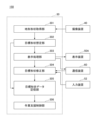
- FIG. 2 is a functional block diagram showing a first example of a functional configuration related to estimation of a target shape of a construction target.
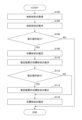
- FIG. 2 is a flowchart schematically showing a first example of processing related to estimation of a target shape of a construction target.
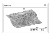
- FIG. 3 is a diagram illustrating an example of display content on a display device, showing a topographical shape around an excavator. It is a figure which shows an example of the display content of a display device showing the estimation result of the target shape of a construction target. It is a figure which shows the estimation result of the target shape of a construction target, and shows another example of the display content of a display device.
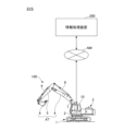
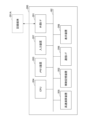
- FIG. 1 is a diagram showing an example of an operation support system.
- FIG. 1 is a diagram illustrating an example of a hardware configuration of an information processing device. It is a functional block diagram which shows the 2nd example of the functional structure regarding estimation of the target shape of a construction target.
- 12 is a flowchart schematically showing a second example of processing related to estimation of a target shape of a construction target.
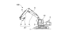
- FIG. 1 and 2 are side views showing an example of the shovel 100.
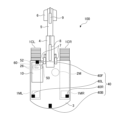
- FIG. 2 is a top view showing an example of the shovel 100.
- FIG. 3 is a diagram showing an example of a configuration related to remote control of an excavator.
- the direction on the shovel 100 or the direction seen from the shovel 100 may be described by defining the direction in which the attachment AT extends (upward direction in FIG. 2) as seen from the top of the shovel 100 as "front".
- the excavator 100 includes a lower traveling body 1, an upper rotating body 3, an attachment AT including a boom 4, an arm 5, and a bucket 6, and a cabin 10.
- the lower traveling body 1 causes the excavator 100 to travel using the crawler 1C.
- the crawler 1C includes a left crawler 1CL and a right crawler 1CR.
- the crawler 1CL is hydraulically driven by a travel hydraulic motor 1ML.
- the crawler 1CL is hydraulically driven by a travel hydraulic motor 1MR.
- the lower traveling body 1 can self-propel.
- the upper rotating body 3 is rotatably mounted on the lower traveling body 1 via the rotating mechanism 2.
- the upper rotating structure 3 turns with respect to the lower traveling structure 1 by hydraulically driving the turning mechanism 2 by the turning hydraulic motor 2M.
- the boom 4 is attached to the center of the front part of the upper revolving body 3 so that it can be raised and raised about a rotation axis along the left-right direction.
- the arm 5 is attached to the tip of the boom 4 so as to be rotatable about a rotation axis extending in the left-right direction.
- the bucket 6 is attached to the tip of the arm 5 so as to be rotatable about a rotation axis extending in the left-right direction.
- the bucket 6 is an example of an end attachment, and is used, for example, in excavation work.
- the bucket 6 is attached to the tip of the arm 5 in such a manner that it can be replaced as appropriate depending on the work content of the shovel 100. That is, instead of the bucket 6, a bucket of a different type than the bucket 6, such as a relatively large bucket, a slope bucket, a dredging bucket, etc., may be attached to the tip of the arm 5. Further, an end attachment of a type other than the bucket, such as an agitator, a breaker, a crusher, etc., may be attached to the tip of the arm 5. Furthermore, a preliminary attachment such as a quick coupling or a tiltrotator may be provided between the arm 5 and the end attachment.
- the boom 4, arm 5, and bucket 6 are hydraulically driven by a boom cylinder 7, an arm cylinder 8, and a bucket cylinder 9, respectively.
- the cabin 10 is a control room where an operator boards and operates the shovel 100.
- the cabin 10 is mounted, for example, on the front left side of the upper revolving body 3.
- the excavator 100 moves the lower traveling body 1 (that is, the pair of left and right crawlers 1CL, 1CR), the upper revolving body 3, the boom 4, the arm 5, the bucket 6, etc. to operate the driven element of.
- the lower traveling body 1 that is, the pair of left and right crawlers 1CL, 1CR
- the upper revolving body 3 that is, the pair of left and right crawlers 1CL, 1CR
- the boom 4 the arm 5, the bucket 6, etc. to operate the driven element of.
- the shovel 100 may be configured to be remotely controlled from outside the shovel 100.
- the interior of the cabin 10 may be unmanned. The following description will proceed on the premise that the operator's operations include at least one of an operator's operation on the operating device 26 by an operator in the cabin 10 and a remote control by an external operator.
- the remote control includes a mode in which the shovel 100 is operated by an operation input regarding the actuator of the shovel 100 performed by the remote control support device 300.
- the remote operation support device 300 is provided, for example, in a management center or the like that manages the work of the excavator 100 from the outside. Further, the remote operation support device 300 may be a portable operation terminal, in which case the operator can remotely control the excavator 100 while directly checking the working status of the excavator 100 from around the excavator 100. can.
- the excavator 100 transmits an image representing the surroundings including the front of the excavator 100 (hereinafter referred to as "surrounding image") based on a captured image output by the imaging device 40 (described later) to the remote operation support device through the communication device 60 (described later). 300. Then, the remote operation support device 300 may display the image (surrounding image) received from the excavator 100 on the display device. Further, various information images (information screens) displayed on the output device 50 (display device) inside the cabin 10 of the excavator 100 may be similarly displayed on the display device of the remote operation support device 300.
- an operator using the remote operation support device 300 can, for example, remotely operate the shovel 100 while checking the display contents such as an image or information screen showing the surroundings of the shovel 100 displayed on the display device. I can do it. Then, the excavator 100 operates the actuators to operate the lower traveling structure 1, the upper rotating structure 3, and the boom 4 in response to a remote control signal indicating the content of the remote control received from the remote control support device 300 through the communication device 60. , arm 5, and bucket 6 may be driven.
- the remote control may include, for example, a mode in which the shovel 100 is operated by external voice input or gesture input to the shovel 100 by a person (for example, a worker) around the shovel 100.
- the excavator 100 receives sounds uttered by surrounding workers, etc. through an audio input device (for example, a microphone), a gesture input device (for example, an imaging device), etc. mounted on the excavator 100. Recognizes gestures etc. performed by Then, the excavator 100 operates the actuator according to the content of the recognized voice or gesture, and moves the lower traveling body 1 (left and right crawlers 1C), the upper rotating body 3, the boom 4, the arm 5, the bucket 6, etc.
- the driven element may also be driven.
- the excavator 100 may automatically operate the actuator regardless of the contents of the operator's operation.
- the excavator 100 has a function to automatically operate at least some of the driven elements such as the lower traveling body 1, the upper revolving body 3, the boom 4, the arm 5, and the bucket 6 (“automatic operation function” or “MC (Machine Control function).
- the automatic operation function includes, for example, a function that automatically operates a driven element (actuator) other than the driven element (actuator) to be operated in response to an operator's operation on the operating device 26 or remote control (a "semi-automatic operation function”). ” or “operation support type MC function”). Furthermore, the automatic operation function includes a function that automatically operates at least a part of a plurality of driven elements (actuators) on the premise that there is no operator operation on the operating device 26 or remote control (a "fully automatic operation function” or a "full automatic operation function”). Fully automatic MC function) may be included. In the excavator 100, when the fully automatic driving function is enabled, the interior of the cabin 10 may be unmanned.
- the semi-automatic driving function, fully automatic driving function, etc. may include a mode in which the operation details of a driven element (actuator) that is a target of automatic driving are automatically determined according to predefined rules.
- the excavator 100 autonomously makes various judgments, and based on the judgment results, autonomously determines the operation of the driven element (actuator) that is the target of automatic driving. (“autonomous driving function") may be included.
- a remote monitoring support device having the same functions as remote operation support device 300 may be provided.
- the remote monitoring support device is, for example, the information processing device 200 described below.
- the supervisor who is the user of the remote monitoring support device can monitor the working status of the excavator 100 while checking the peripheral image displayed on the display device of the remote monitoring support device. For example, if the supervisor determines that it is necessary from a safety perspective, the supervisor may intervene in the operator's operation of the excavator 100 and bring it to an emergency stop by inputting a predetermined input using the input device of the remote monitoring support device. be able to.
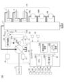
- FIG. 4 is a block diagram showing an example of the hardware configuration of the shovel 100.
- the path through which mechanical power is transmitted is a double line
- the path through which high-pressure hydraulic oil that drives the hydraulic actuator flows is a solid line
- the path through which pilot pressure is transmitted is a broken line
- the path through which electrical signals are transmitted is shown. Each route is indicated by a dotted line.
- the excavator 100 includes a hydraulic drive system for hydraulically driving the driven elements, an operation system for operating the driven elements, a user interface system for exchanging information with the user, a communication system for communicating with the outside, a control system for various controls, etc. Contains each component of.
- the hydraulic drive system of the excavator 100 includes hydraulic pressure for hydraulically driving each of the driven elements such as the lower traveling body 1 (left and right crawlers 1C), the upper rotating body 3, and the attachment AT, as described above. Includes actuator HA. Further, the hydraulic drive system of the excavator 100 according to the present embodiment includes an engine 11, a regulator 13, a main pump 14, and a control valve 17.
- the hydraulic actuator HA includes travel hydraulic motors 1ML and 1MR, a swing hydraulic motor 2M, a boom cylinder 7, an arm cylinder 8, a bucket cylinder 9, and the like.
- the excavator 100 part or all of the hydraulic actuator HA may be replaced with an electric actuator.
- the excavator 100 may be a hybrid excavator or an electric excavator.
- the engine 11 is the prime mover of the excavator 100 and is the main power source in the hydraulic drive system.
- the engine 11 is, for example, a diesel engine that uses light oil as fuel.
- the engine 11 is mounted, for example, at the rear of the upper revolving structure 3.
- the engine 11 rotates at a predetermined target rotation speed under direct or indirect control by a controller 30, which will be described later, and drives the main pump 14 and the pilot pump 15.
- the regulator 13 controls (adjusts) the discharge amount of the main pump 14 under the control of the controller 30.
- the regulator 13 adjusts the angle of the swash plate (hereinafter referred to as "tilt angle") of the main pump 14 in accordance with a control command from the controller 30.
- the main pump 14 supplies hydraulic oil to the control valve 17 through a high-pressure hydraulic line.
- the main pump 14 is, for example, mounted at the rear of the upper revolving structure 3, like the engine 11.
- the main pump 14 is driven by the engine 11 as described above.
- the main pump 14 is, for example, a variable displacement hydraulic pump, and as described above, the stroke length of the piston is adjusted by adjusting the tilt angle of the swash plate by the regulator 13 under the control of the controller 30, and the stroke length of the piston is adjusted.
- the flow rate and discharge pressure are controlled.
- the control valve 17 drives the hydraulic actuator HA in accordance with the contents of the operator's operation on the operating device 26 or remote control, or the operation command corresponding to the automatic operation function.
- the control valve 17 is mounted, for example, in the center of the upper revolving body 3.
- the control valve 17 is connected to the main pump 14 via a high-pressure hydraulic line, and controls the hydraulic fluid supplied from the main pump 14 according to an operator's operation or an operation command corresponding to an automatic operation function. , selectively supplying each hydraulic actuator.
- the control valve 17 includes a plurality of control valves (also referred to as "direction switching valves") that control the flow rate and flow direction of the hydraulic oil supplied from the main pump 14 to each of the hydraulic actuators HA.
- the operating system of the excavator 100 includes a pilot pump 15, an operating device 26, a hydraulic control valve 31, a shuttle valve 32, and a hydraulic control valve 33.
- the pilot pump 15 supplies pilot pressure to various hydraulic devices via the pilot line 25.
- the pilot pump 15 is, for example, mounted at the rear of the upper revolving structure 3, like the engine 11.
- the pilot pump 15 is, for example, a fixed capacity hydraulic pump, and is driven by the engine 11 as described above.
- pilot pump 15 may be omitted.
- the relatively high pressure hydraulic oil discharged from the main pump 14 may be reduced in pressure by a predetermined pressure reducing valve, and then the relatively low pressure hydraulic oil may be supplied as pilot pressure to various hydraulic devices.
- the operating device 26 is provided near the cockpit of the cabin 10 and is used by the operator to operate various driven elements. Specifically, the operating device 26 is used for an operator to operate the hydraulic actuator HA that drives each driven element, and as a result, the operator operates the driven element to be driven by the hydraulic actuator HA. can be realized.
- the operating device 26 includes a pedal device and a lever device for operating each driven element (hydraulic actuator HA).
- the operating device 26 is of a hydraulic pilot type. Specifically, the operating device 26 utilizes hydraulic oil supplied from the pilot pump 15 through the pilot line 25 and a pilot line 25A branching from the pilot line 25, and applies pilot pressure according to the operation content to the pilot line 27A on the secondary side. Output to. Pilot line 27A is connected to one inlet port of shuttle valve 32 and connected to control valve 17 via pilot line 27, which is connected to an outlet port of shuttle valve 32. Thereby, a pilot pressure can be input to the control valve 17 via the shuttle valve 32 in accordance with the operation contents regarding various driven elements (hydraulic actuator HA) in the operating device 26. Therefore, the control valve 17 can drive each hydraulic actuator HA according to the operation performed on the operating device 26 by an operator or the like.
- the operating device 26 may be electrical.
- the pilot line 27A, shuttle valve 32, and hydraulic control valve 33 are omitted.
- the operating device 26 outputs an electrical signal (hereinafter referred to as an "operating signal") according to the content of the operation, and the operating signal is taken into the controller 30.
- the controller 30 outputs a control command according to the content of the operation signal, that is, a control signal according to the content of the operation on the operating device 26 to the hydraulic control valve 31.
- pilot pressure corresponding to the operation details of the operating device 26 is inputted from the hydraulic control valve 31 to the control valve 17, and the control valve 17 drives each hydraulic actuator HA according to the operation details of the operating device 26. be able to.
- control valves built into the control valve 17 and driving the respective hydraulic actuators HA may be of an electromagnetic solenoid type.
- the operation signal output from the operation device 26 may be directly input to the control valve 17, that is, to an electromagnetic solenoid type control valve.
- part or all of the hydraulic actuator HA may be replaced with an electric actuator.
- the controller 30 may output a control command according to the operation content of the operating device 26 or the remote control content specified by the remote control signal to the electric actuator or a driver driving the electric actuator.
- the operating device 26 may be omitted.
- the hydraulic control valve 31 is provided for each driven element (hydraulic actuator HA) to be operated by the operating device 26 and for each drive direction of the driven element (hydraulic actuator HA) (for example, the raising direction and lowering direction of the boom 4). . That is, two hydraulic control valves 31 are provided for each double-acting hydraulic actuator HA.
- the hydraulic control valve 31 is provided, for example, in the pilot line 25B between the pilot pump 15 and the control valve 17, and is configured to be able to change its flow path area (that is, the cross-sectional area through which hydraulic oil can flow). good. Thereby, the hydraulic control valve 31 can output a predetermined pilot pressure to the secondary side pilot line 27B using the hydraulic oil of the pilot pump 15 supplied through the pilot line 25B.
- the hydraulic control valve 31 can indirectly apply a predetermined pilot pressure according to the control signal from the controller 30 to the control valve 17 through the shuttle valve 32 between the pilot line 27B and the pilot line 27. . Therefore, the controller 30 can cause the hydraulic control valve 31 to supply pilot pressure to the control valve 17 according to the operation command corresponding to the automatic operation function, thereby realizing operation of the excavator 100 according to the automatic operation function.
- the controller 30 may control the hydraulic control valve 31 to realize remote control of the excavator 100, for example. Specifically, the controller 30 outputs to the hydraulic control valve 31 a control signal corresponding to the content of the remote operation specified by the remote operation signal received from the remote operation support device 300, using the communication device 60. Thereby, the controller 30 can cause the hydraulic control valve 31 to supply pilot pressure corresponding to the content of the remote control to the control valve 17, and realize the operation of the shovel 100 based on the operator's remote control.
- the controller 30 causes the hydraulic control valve 31 to directly supply pilot pressure according to the operation details (operation signal) of the operating device 26 to the control valve 17, and The operation of the excavator 100 based on the above can be realized.
- the shuttle valve 32 has two inlet ports and one outlet port, and outputs the hydraulic oil having the higher pilot pressure of the pilot pressures input to the two inlet ports to the outlet port.
- the shuttle valve 32 is provided for each driven element (hydraulic actuator HA) to be operated by the operating device 26 and for each drive direction of the driven element (hydraulic actuator HA).
- One of the two inlet ports of the shuttle valve 32 is connected to the pilot line 27A on the secondary side of the operating device 26 (specifically, the above-mentioned lever device or pedal device included in the operating device 26), and the other is It is connected to the pilot line 27B on the secondary side of the hydraulic control valve 31.
- the outlet port of shuttle valve 32 is connected to the pilot port of the corresponding control valve of control valve 17 through pilot line 27 .
- the corresponding control valve is a control valve that drives a hydraulic actuator that is operated by the above-mentioned lever device or pedal device connected to one inlet port of the shuttle valve 32. Therefore, these shuttle valves 32 each control the higher of the pilot pressure in the pilot line 27A on the secondary side of the operating device 26 and the pilot pressure on the pilot line 27B on the secondary side of the hydraulic control valve 31, respectively. It can act on the pilot port of the control valve.
- the controller 30 controls the corresponding control valve by causing the hydraulic control valve 31 to output a pilot pressure higher than the pilot pressure on the secondary side of the operating device 26, regardless of the operator's operation on the operating device 26. be able to. Therefore, the controller 30 controls the operation of the driven elements (lower traveling structure 1, upper rotating structure 3, attachment AT) regardless of the operation state of the operating device 26 by the operator, and realizes a remote control function and an automatic driving function. can do.
- the hydraulic control valve 33 is provided in the pilot line 27A that connects the operating device 26 and the shuttle valve 32.
- the hydraulic control valve 33 is configured to be able to change its flow path area, for example.
- the hydraulic control valve 33 operates according to a control signal input from the controller 30.
- the controller 30 can forcibly reduce the pilot pressure output from the operating device 26 when the operating device 26 is being operated by the operator. Therefore, even when the operating device 26 is being operated, the controller 30 can forcibly suppress or stop the operation of the hydraulic actuator corresponding to the operation of the operating device 26.
- the controller 30 can reduce the pilot pressure output from the operating device 26 to be lower than the pilot pressure output from the hydraulic control valve 31, for example, even when the operating device 26 is being operated. I can do it.
- the controller 30 applies a desired pilot pressure to the pilot port of the control valve in the control valve 17, for example, regardless of the operation details of the operating device 26. It can be made to work reliably. Therefore, by controlling the hydraulic control valve 33 in addition to the hydraulic control valve 31, for example, the controller 30 can more appropriately realize the remote control function and automatic operation function of the excavator 100.
- the user interface system of excavator 100 includes an operating device 26, an output device 50, and an input device 52.
- the output device 50 outputs various information to the user of the excavator 100 (for example, the operator in the cabin 10 or an external remote control operator) and the people around the excavator 100 (for example, a worker or a driver of a work vehicle). Output.
- the output device 50 includes a lighting device and a display device 50A (see FIG. 5) that output various information in a visual manner.
- the lighting equipment is, for example, a warning light (indicator lamp) or the like.
- the display device 50A is, for example, a liquid crystal display or an organic EL (Electroluminescence) display.
- lighting equipment and a display device 50A may be provided inside the cabin 10 and output various information visually to an operator inside the cabin 10.
- the lighting equipment and the display device 50A may be provided, for example, on the side surface of the revolving upper structure 3, and may output various information visually to workers and the like around the excavator 100.
- the output device 50 includes a sound output device that outputs various information in an auditory manner.
- the sound output device includes, for example, a buzzer, a speaker, and the like.
- the sound output device is, for example, provided inside or outside the cabin 10 and outputs various information audibly to the operator inside the cabin 10 and the people (workers, etc.) around the excavator 100. good.
- the output device 50 may include a device that outputs various information using a tactile method such as vibration of the cockpit.
- the input device 52 accepts various inputs from the user of the excavator 100, and signals corresponding to the accepted inputs are taken into the controller 30.
- the input device 52 is provided inside the cabin 10 , for example, and receives input from an operator inside the cabin 10 . Further, the input device 52 may be provided, for example, on a side surface of the revolving upper structure 3, and may receive input from a worker or the like around the excavator 100.
- the input device 52 includes an operation input device that accepts mechanical input from the user.
- the operation input device may include a touch panel mounted on the display device, a touch pad installed around the display device, a button switch, a lever, a toggle, a knob switch provided on the operation device 26 (lever device), etc. .
- the input device 52 may include a voice input device that accepts voice input from the user.
- the audio input device includes, for example, a microphone.
- the input device 52 may include a gesture input device that accepts gesture input from the user.
- the gesture input device includes, for example, an imaging device that captures an image of a gesture performed by a user.
- the input device 52 may include a biometric input device that receives biometric input from the user.
- the biometric input includes, for example, input of biometric information such as a user's fingerprint or iris.
- the communication system of the excavator 100 includes a communication device 60.
- the communication device 60 is connected to an external communication line and communicates with a device provided separately from the excavator 100.
- Devices provided separately from the excavator 100 may include devices external to the excavator 100 as well as portable terminal devices (portable terminals) brought into the cabin 10 by the user of the excavator 100.
- the communication device 60 may include, for example, a mobile communication module that complies with standards such as 4G ( 4th Generation) and 5G ( 5th Generation). Further, the communication device 60 may include, for example, a satellite communication module. Further, the communication device 60 may include, for example, a WiFi communication module, a Bluetooth (registered trademark) communication module, or the like. Furthermore, the communication device 60 may include a plurality of communication devices depending on the communication lines to be connected.
- the communication device 60 communicates with external devices such as the information processing device 200 and the remote operation support device 300 in the work site through a local communication line built at the work site.
- the local communication line is, for example, a local 5G (so-called local 5G) mobile communication line built at a work site or a local area network (LAN) using WiFi 6.
- the communication device 60 communicates with an information processing device 200, a remote operation support device 300, etc. located outside the work site through a wide area communication line that includes the work site, that is, a wide area network (WAN).
- a wide area network includes, for example, a wide area mobile communication network, a satellite communication network, an Internet network, and the like.
- the control system of excavator 100 includes a controller 30. Further, the control system of the excavator 100 according to the present embodiment includes an operating pressure sensor 29, an imaging device 40, and sensors S1 to S5.
- the controller 30 performs various controls regarding the shovel 100.
- the controller 30 may be realized by arbitrary hardware or a combination of arbitrary hardware and software.
- the controller 30 includes an auxiliary storage device 30A, a memory device 30B, a CPU (Central Processing Unit) 30C, and an interface device 30D, which are connected via a bus B1.
- auxiliary storage device 30A a memory device 30B
- CPU Central Processing Unit
- interface device 30D an interface device 30D
- the auxiliary storage device 30A is a non-volatile storage means, and stores installed programs as well as necessary files, data, etc.
- the auxiliary storage device 30A is, for example, an EEPROM (Electrically Erasable Programmable Read-Only Memory) or a flash memory.
- the memory device 30B loads the program in the auxiliary storage device 30A so that it can be read by the CPU 30C.
- the memory device 30B is, for example, an SRAM (Static Random Access Memory).
- the CPU 30C executes a program loaded into the memory device 30B, and implements various functions of the controller 30 according to instructions of the program.
- the interface device 30D functions as a communication interface for connecting to a communication line inside the excavator 100, for example.
- the interface device 30D may include a plurality of different types of communication interfaces depending on the type of communication line to be connected.
- the interface device 30D functions as an external interface for reading data from and writing data to the recording medium.
- the recording medium is, for example, a dedicated tool that is connected to a connector installed inside the cabin 10 with a detachable cable.
- the recording medium may be a general-purpose recording medium such as an SD memory card or a USB (Universal Serial Bus) memory.
- programs for realizing various functions of the controller 30 can be provided by, for example, a portable recording medium and installed in the auxiliary storage device 30A of the controller 30. Further, the program may be downloaded from another computer outside the excavator 100 through the communication device 60 and installed in the auxiliary storage device 30A.
- controller 30 may be realized by another controller (control device). That is, the functions of the controller 30 may be realized in a distributed manner by a plurality of controllers.
- the operating pressure sensor 29 detects the pilot pressure on the secondary side (pilot line 27A) of the hydraulic pilot type operating device 26, that is, the pilot pressure corresponding to the operating state of each driven element (hydraulic actuator) in the operating device 26. To detect. A detection signal of pilot pressure corresponding to the operating state of each driven element (hydraulic actuator HA) in the operating device 26 by the operating pressure sensor 29 is taken into the controller 30.
- the operating device 26 is an electric type, the operating pressure sensor 29 is omitted. This is because the controller 30 can grasp the operating state of each driven element through the operating device 26 based on the operating signal taken in from the operating device 26.
- the imaging device 40 acquires images around the excavator 100.
- the imaging device 40 also generates three-dimensional data (hereinafter simply referred to as "the object's three-dimensional shape") representing the position and external shape of the object around the shovel 100 within the imaging range (angle of view) based on the acquired image and distance-related data described below. "original data”) may be obtained (generated).
- the three-dimensional data of objects around the shovel 100 is, for example, coordinate information data of a point group representing the surface of the object, distance image data, and the like.
- the imaging device 40 includes a camera 40F that images the front of the upper revolving structure 3, a camera 40B that images the rear of the upper revolving structure 3, and a camera 40L that images the left side of the upper revolving structure 3. , and a camera 40R that images the right side of the upper rotating body 3.
- the imaging device 40 can image the entire circumference of the excavator 100, that is, the range covering the angular direction of 360 degrees, when the excavator 100 is viewed from above.
- the operator visually recognizes peripheral images such as captured images of the cameras 40B, 40L, and 40R and processed images generated based on the captured images through the output device 50 (display device 50A) and the display device for remote control. The left, right, and rear sides of the rotating body 3 can be confirmed.
- the operator can check the operation of the attachment AT including the bucket 6 by visually checking peripheral images such as images captured by the camera 40F and processed images generated based on the captured images through the remote control display device.
- the excavator 100 can be remotely controlled.
- the cameras 40F, 40B, 40L, and 40R may be collectively or individually referred to as "camera 40X.”
- the camera 40X is, for example, a monocular camera.
- the camera 40X acquires data regarding distance (depth) in addition to two-dimensional images, such as a stereo camera, a TOF (Time Of Flight) camera, etc. (hereinafter collectively referred to as a "3D camera"). It may be possible.
- Output data (for example, image data, three-dimensional data of objects around the excavator 100, etc.) of the imaging device 40 (camera 40X) is taken into the controller 30 through a one-to-one communication line or an in-vehicle network.
- the controller 30 can monitor objects around the excavator 100 based on the output data of the camera 40X.
- the controller 30 can determine the surrounding environment of the excavator 100 based on the output data of the camera 40X.
- the controller 30 can determine the posture state of the attachment AT shown in the captured image based on the output data of the camera 40X (camera 40F).
- the controller 30 can determine the attitude state of the body of the excavator 100 (the upper revolving body 3) based on the output data of the camera 40X, with reference to objects around the excavator 100.
- the cameras 40F, 40B, 40L, and 40R may be omitted.
- the camera 40F and the camera 40L may be omitted. This is because it is relatively easy for the operator in the cabin 10 to check the front and left side of the excavator 100.
- a distance sensor may be provided in the upper revolving body 3. The distance sensor is attached to the upper part of the upper revolving body 3, for example, and acquires data regarding the distance and direction of surrounding objects with respect to the shovel 100 as a reference.
- the distance sensor may acquire (generate) three-dimensional data (for example, coordinate information data of a point group) of objects around the shovel 100 within the sensing range based on the acquired data.
- the distance sensor is, for example, LIDAR (Light Detection and Ranging).
- the distance sensor may be, for example, a millimeter wave radar, an ultrasonic sensor, an infrared sensor, or the like.
- the sensor S1 is attached to the boom 4 and detects the attitude angle (hereinafter referred to as "boom angle") around the rotation axis of the base end corresponding to the connection part of the boom 4 with the upper revolving structure 3.
- the sensor S1 includes, for example, a rotary potentiometer, a rotary encoder, an acceleration sensor, an angular acceleration sensor, a 6-axis sensor, an IMU (Inertial Measurement Unit), and the like.
- the same may be applied to the sensor S2 and the sensor S4.
- the sensor S1 may include a cylinder sensor that detects the extended/contracted position of the boom cylinder 7.
- a detection signal of the boom angle by the sensor S1 is taken into the controller 30. Thereby, the controller 30 can grasp the attitude state of the boom 4.
- the sensor S2 is attached to the arm 5 and detects the posture angle (hereinafter referred to as "arm angle") around the rotation axis of the base end of the arm 5, which corresponds to the connection part with the boom 4.
- the arm angle detection signal from the sensor S2 is taken into the controller 30. Thereby, the controller 30 can grasp the posture state of the arm 5.
- the sensor S3 is attached to the bucket 6 and detects the attitude angle (hereinafter referred to as "arm angle") around the rotation axis of the base end corresponding to the connection part with the arm 5 of the bucket 6.
- a detection signal of the arm angle by the sensor S3 is taken into the controller 30. Thereby, the controller 30 can grasp the attitude state of the bucket 6.
- the sensor S4 detects the inclination state of the aircraft body (for example, the upper rotating body 3) with respect to a predetermined reference plane (for example, a horizontal plane).
- the sensor S4 is attached to the revolving upper structure 3, and measures the inclination angle of the excavator 100 (i.e., the revolving upper structure 3) about two axes in the front-rear direction and the left-right direction (hereinafter, "front-rear inclination angle” and “lateral inclination angle”). ”) is detected.
- a detection signal corresponding to the inclination angle (front/rear inclination angle and left/right inclination angle) detected by the sensor S ⁇ b>4 is taken into the controller 30 . Thereby, the controller 30 can grasp the tilting state of the aircraft body (upper rotating body 3).
- the sensor S5 is attached to the revolving upper structure 3 and outputs detection information regarding the turning state of the revolving upper structure 3.
- the sensor S5 detects, for example, the turning angular velocity and turning angle of the upper rotating body 3.
- the sensor S5 includes, for example, a gyro sensor, a resolver, a rotary encoder, and the like. Detection information regarding the turning state detected by the sensor S5 is taken into the controller 30. Thereby, the controller 30 can grasp the turning state such as the turning angle of the upper rotating body 3.
- the senor S4 includes a gyro sensor, a 6-axis sensor, an IMU, etc. that can detect angular velocity around three axes
- the turning state for example, turning angular velocity
- sensor S5 may be omitted.
- at least some of the sensors S1 to S5 may be omitted.
- target shape estimation function [Overview of target shape estimation function]
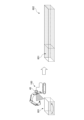
- FIG. 5 is a diagram schematically showing an example of a method for estimating the target shape of a construction target in slope work.
- FIG. 6 is a diagram schematically showing an example of a method for estimating a target shape in bed excavation work.
- the construction target is an object that the excavator 100 forms on the ground or the like through construction work.
- the construction work includes, for example, slope work, floor digging work, land leveling work, and the like.
- the construction targets include, for example, horizontal surfaces, slopes, ditches, and embankments.
- the target shape of the construction target is the target shape of the construction target that is expected to be finally realized by the work of the excavator 100.
- the target shape of the construction target is, for example, a target construction surface formed as a plane. Further, the target shape of the construction target may be a target construction surface formed by a curved surface with a predetermined curvature.
- the shovel 100 (controller 30) estimates the target shape of the construction target based on the shape of a part of the construction target that has been constructed by the operation of the shovel by a skilled person.
- the estimated target shape of the construction target may be the entire target shape of the construction target, or the target shape of a partial area of the construction target that is wider than some of the areas that have already been constructed. It's okay.
- the shovel used by the skilled person for construction work on the target may be the shovel 100 or another shovel different from the shovel 100.
- the expert is, for example, an operator who has relatively long experience in operating a shovel and has a relatively high level of experience in operating a shovel.
- a partially constructed area 501 of the slope to be constructed is formed.
- the area 501 is constructed in advance based on the operation of a shovel by a skilled person.
- the excavator 100 uses the imaging device 40 to image the shape of the region 501, and acquires shape data of the region 501 based on the output of the imaging device 40.
- the excavator 100 (controller 30) estimates a target construction surface 502 corresponding to the target shape of the construction target based on the shape data of the area 501.
- the controller 30 estimates the target construction surface 502 by extending the planar shape of the region 501 in the width direction of the slope, or by duplicating and arranging them in the width direction, and acquires data regarding the target construction surface 502. .
- this estimation method may be referred to as a "first estimation method" for the target shape of the work object.
- the controller 30 performs machine learning using a teacher data set that is a combination of data on the shape of a part of the slope to be constructed that has already been constructed and data on the shape of the target construction surface of the slope to be constructed.
- a trained model may also be used.
- the controller 30 estimates the target construction surface 502 based on the output data of the learned model by applying the shape data of the region 501 as input data to the trained model, and the data of the target construction surface 502. can be obtained.
- the groove 601 is constructed in advance based on the operation of a shovel by a skilled person.
- the excavator 100 uses the imaging device 40 to image the shape of the groove 601, and acquires shape data of the groove 601 based on the output of the imaging device 40.
- the shovel 100 estimates a target construction surface 602 corresponding to the target shape of the groove to be constructed based on the shape data of the groove 601.
- the target construction surface 602 includes a target construction surface corresponding to the side surfaces at both ends in the width direction of the groove, a target construction surface corresponding to the side surfaces at both ends in the length direction of the groove, and a target construction surface corresponding to the bottom of the groove.
- the controller 30 estimates the target construction surface 602 using the first estimation method. Specifically, the controller 30 creates the target construction surface 602 by extending the shape of the side surfaces at both widthwise ends of the groove 601 in the length direction of the groove to be constructed, or by duplicating and arranging them in the length direction. The target construction surface corresponding to the side surfaces at both ends in the width direction of the groove may be estimated. In addition, the controller 30 extends the shape of the bottom of the groove 601 in the length direction of the groove to be constructed, or duplicates and arranges them in the length direction, so that the shape corresponds to the bottom of the groove in the target construction surface 602. The target construction surface may be estimated.
- the controller 30 also adjusts the length of the groove on the target construction surface 602 by using the shape of both end faces in the length direction of the groove 601 as is or by offsetting the position in the length direction of the groove to be constructed.
- the target construction surface corresponding to the side surfaces at both ends in the horizontal direction may be estimated.
- the controller 30 may estimate the target construction surface 602 using a second estimation method. Specifically, the controller 30 performs machine learning using a teacher data set that is a combination of data on the shape of a part of the groove to be constructed that has already been constructed and data on the shape of the target construction surface of the groove to be constructed. A trained model may also be used. In this case, the controller 30 uses the shape data of the groove 601 as input data and applies the learned model to estimate the target construction surface 602 based on the output data of the learned model, and calculates the data of the target construction surface 602. can be obtained.
- the controller 30 estimates the target shape of the construction target based on the shape data of a part of the construction target that has already been constructed by operating a shovel by an expert, and calculates the data regarding the target shape. can be obtained. Thereby, the controller 30 can more easily acquire data regarding the target shape of the construction target. Therefore, since there is no need to prepare data regarding the target shape in advance, there is no need for the user to manually input parameters regarding the target shape, for example. For example, even at small-scale construction sites where there is no system or funding to prepare data on the target shape in advance, it is possible to acquire data on the target shape and adopt technology related to machine guidance and machine control. Work efficiency can be improved.
- the target shape estimation function is applied to the excavator 100 operated by an operator in the cabin 10 or a remote operator.
- the excavator 100 can support the operator's operation using the machine guidance function and the operation support type MC function based on the data regarding the target shape estimated by the target shape estimation function.
- the target shape estimation function may be applied to the excavator 100 that operates with a fully automatic operation function (fully automatic MC function). In this case, the excavator 100 can automatically perform construction so that the work target has the target shape using the fully automatic operation function based on the data regarding the target shape estimated by the target shape estimation function.
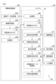
- FIG. 7 is a functional block diagram showing a first example of a functional configuration related to estimating the target shape of the construction target.
- the excavator 100 includes a support device 150.
- the support device 150 supports the work of the excavator 100.
- the support device 150 includes a controller 30, an imaging device 40, a display device 50A, an input device 52, and a communication device 60.
- the controller 30 includes, as functional units, a terrain shape acquisition unit 301, a target shape estimation unit 302, a display processing unit 303, a target shape modification unit 304, a target shape data storage unit 305, and a work support control unit 306. include.
- the topographical shape acquisition unit 301 acquires data regarding the topographical shape of the location where the construction target is formed around the excavator 100, including a part of the construction target that has already been constructed, based on the output of the imaging device 40 and the distance sensor. get.
- the data regarding the topographic shape includes, for example, both partially constructed locations and unconstructed locations of the construction target.
- the data regarding the topographic shape may be, for example, image data or three-dimensional data.
- the target shape estimation unit 302 estimates the target shape of the construction target using the first estimation method described above based on the data acquired by the terrain shape acquisition unit 301, and acquires data regarding the target shape of the construction target. .
- the display processing unit 303 causes the display device 50A to display the target shape of the construction target as the estimation result of the target shape estimation unit 302. Further, when the excavator 100 is remotely controlled or monitored, the display processing unit 303 transmits image data of the target shape of the construction target as the estimation result of the target shape estimating unit 302 to the remote operation support device 300 via the communication device 60. It may also be sent to a remote monitoring support device. Thereby, the display processing unit 303 can display the target shape of the construction target as the estimation result of the target shape estimating unit 302 on the remote operation support device 300 or the display device of the remote operation support device. This allows the user (operator) to visually confirm data regarding the target shape of the construction target.
- the display processing unit 303 also causes the display device 50A to display the target shape of the construction target as the estimation result of the target shape estimating unit 302 and the current topographic shape based on the output of the imaging device 40 so that they can be compared. (See FIGS. 10 and 11). Similarly, the display processing unit 303 sends an image to the remote operation support device 300 or the It may also be transmitted to a remote monitoring support device. Thereby, the user (operator) can determine whether an appropriate target shape has been generated (estimated) by comparing the current topographic shape and the target shape of the construction target.
- the target shape modification unit 304 modifies data regarding the target shape of the construction target as the estimation result of the target shape estimation unit 302, in response to a predetermined input from the user (operator). Input from the user is accepted by the input device 52. Further, when the excavator 100 is remotely operated or monitored, input from the user is received from the remote operation support device 300 or the remote monitoring support device through the communication device 60. For example, in a three-dimensional orthogonal coordinate system, the target shape modification unit 304 performs translational movement in directions along each of the X-axis, Y-axis, and Z-axis, and Data regarding the target shape of the construction target is corrected using a total of six degrees of freedom including rotational movement. Further, the target shape modification unit 304 may modify data regarding the target shape of the construction target with a total of 9 degrees of freedom including expansion or reduction in directions along each of the X-axis, Y-axis, and Z-axis. .
- the target shape data storage unit 305 stores data regarding the target shape of the construction target. Specifically, data regarding the target shape of the construction target as an estimation result by the target shape estimation unit 302 or data regarding the target shape of the construction target as a modification result by the target shape modification unit 304 may be stored.
- the work support control unit 306 performs control to support work related to the construction of the construction target based on data regarding the target shape of the construction target.
- the work support control unit 306 performs control regarding machine guidance based on data regarding the target shape of the construction target. Specifically, the work support control unit 306 notifies the operator of information such as the distance between the target shape and the work area such as the toe or back of the bucket 6 through the output device 50 such as the display device 50A and the communication device 60. You may do so.
- the work support control unit 306 may perform control related to machine control (automatic driving function) based on data related to the target shape of the construction target. Specifically, the work support control unit 306 controls the hydraulic control valve 31 to support the operator's operation, or to target the work area such as the toe or back of the bucket 6 regardless of the operator's operation. Attachment AT or the like may be operated so as to move along a trajectory that follows the shape.
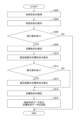
- FIG. 8 is a flowchart schematically showing a first example of processing related to estimating the target shape of the construction target.
- FIG. 9 is a diagram illustrating an example of display content (screen 900) on display device 50A, showing the topographical shape around shovel 100.
- FIGS. 10 and 11 are diagrams illustrating an example and other examples of the display contents of the display device 50A, which represent the estimation results of the target shape of the construction target. Specifically, FIG. 10 is a diagram showing the display contents of the display device 50A when the target shape of the construction target as the estimation result is appropriate, and FIG. 11 shows the display content of the display device 50A when the target shape of the construction target as the estimation result is It is a figure which shows the display content of 50 A of display devices when inappropriate.
- the flowchart in FIG. 8 is started, for example, when a predetermined input from a user (operator, supervisor, etc.) is received through the input device 52 or the communication device 60.
- step S102 an example of an acquisition step
- the terrain shape acquisition unit 301 acquires image data around the shovel 100 based on the output of the imaging device 40, or images around the shovel 100 based on the image data.
- step S102 Upon completion of the process in step S102, the controller 30 proceeds to step S104.
- step S104 the display processing unit 303 displays an image representing the topographic shape around the excavator 100 at the location where the construction target is formed on the display device 50A, remote operation support device 300, etc. based on the data acquired in step S102. (See Figure 9).
- images 901 to 903 are displayed on a screen 900 of the display device 50A.
- the image 901 is an image representing the topographical shape around the shovel 100 where the construction target (in this example, a slope) is to be formed. Specifically, in the image 901, the terrain shape around the excavator 100 is expressed by three-dimensional mesh data. This allows the user to recognize the current topographical shape of the location where the construction target is to be formed.
- the image 902 is an icon for operation to execute the process of estimating the target shape of the construction target. Thereby, the user can execute the process of estimating the target shape of the construction target by operating the icon of the image 902 through the input device 52 or the like (see step S106 in FIG. 8).
- Image 903 is an icon for operation to end the process of the flowchart in FIG. 8 and return to a predetermined screen. The same applies to images 1004 and 1104, which will be described later. Thereby, the process of the flowchart of FIG. 8 can be stopped midway.
- step S104 the controller 30 proceeds to step S106.
- step S106 the controller 30 determines whether an operation has been performed through the input device 52 or the like to execute a process of estimating the target shape of the construction target.
- the controller 30 proceeds to step S108 when an operation is performed to perform the process of estimating the target shape of the construction target, and otherwise proceeds to step S108 (for example, when the image 903 is operated or after a certain period of time has elapsed), the controller 30 proceeds to step S108. is not performed), the processing of the current flowchart ends.
- steps S104 and S106 may be omitted.
- step S108 the target shape estimating unit 302 estimates the target shape of the construction target using the first estimation method described above based on the data acquired in step S102, and estimates the target shape of the construction target using the first estimation method described above. Obtain data regarding the target shape.
- step S108 Upon completion of the process in step S108, the controller 30 proceeds to step S110.
- step S110 the target shape of the construction target based on the estimation result in step S108 is displayed on the display device 50A, the remote operation support device 300 (display device), etc. (see FIGS. 10 and 11).
- a screen 1000 includes images 1001 to 1005.
- a screen 1100 includes images 1101 to 1105.
- Images 1001 and 1101, like image 901 in FIG. 9, are images representing the topographical shape around the shovel 100 at a location where a construction target (in this example, a slope) is to be formed.
- Images 1002 and 1102 are images representing the target shape (target construction surface) of the construction target, respectively.
- Images 1003 and 1103 are icons for operation to confirm the target shape (target construction surface) of the construction target to the current display content.
- Images 1004 and 1104 are icons for operation to move to a screen for modifying the target shape of the construction target from the current display content.
- the target shape of the construction target (image 1002) is appropriately estimated with respect to the current topographical shape around the excavator 100 (image 1001). Therefore, by operating the icon of the image 1003 through the input device 52, the remote operation support device 300, etc., the user can determine the target shape of the construction target based on the data of the current display content.
- the target shape of the construction target (image 1102) is estimated in a form that does not match the current shape of the area around the shovel 100 at all. Therefore, the user can modify the target shape of the construction target by operating the operation icon in the image 1104 through the input device 52, the remote operation support device 300, or the like.
- step S110 the controller 30 proceeds to step S112.
- step S112 the controller 30 determines whether an operation has been performed to modify the target shape of the construction target through the input device 52, the remote operation support device 300 (input device), or the like.
- the process proceeds to step S114, and when the operation to determine the target shape of the construction target is performed, the process advances to step S116.
- step S114 the target shape modification unit 304 modifies data regarding the target shape of the construction target in response to input from the user through the input device 52 or the remote operation support device 300.
- step S114 Upon completion of the process in step S114, the controller 30 proceeds to step S116.
- step S116 the controller 30 determines the target shape and stores data regarding the target shape in the target shape data storage unit 305.
- step S116 the controller 30 ends the process of the current flowchart.
- the support device 150 estimates the target shape of the construction target based on the shape of some parts that have been constructed by the operation of the shovel by a skilled person, and further collects data regarding the target shape of the construction target. can be easily obtained.
- the support device 150 can modify the target shape of the construction target as the estimation result in response to input from the user.
- the shovel 100 may be a component of the operation support system SYS.
- the operation support system SYS includes a shovel 100 and an information processing device 200.
- the operation support system SYS uses the information processing device 200 to cooperate with the excavator 100 and provides support regarding the operation of the excavator 100.
- the number of excavators 100 included in the operation support system SYS may be one or multiple.
- the excavator 100 is a work machine to which operation support is provided in the operation support system SYS.
- the information processing device 200 cooperates with the shovel 100 by communicating with the shovel 100, and provides support regarding the operation of the shovel 100.
- the information processing device 200 is, for example, a server installed in a management office within the work site of the excavator 100 or a management center that manages the operating status of the excavator 100, etc. located at a location different from the work site of the excavator 100. It is a terminal device for management purposes.
- the management terminal device may be a stationary terminal device such as a desktop PC (Personal Computer), or a portable terminal device such as a tablet terminal, smartphone, or laptop PC. terminal).
- workers at the work site, supervisors who supervise work, managers who manage the work site, and the like can carry the portable information processing device 200 and move around the work site.
- the operator can, for example, bring the portable information processing device 200 into the cabin of the excavator 100.
- the information processing device 200 acquires data regarding the operating state from the excavator 100, for example. Thereby, the information processing device 200 can grasp the operating state of the shovel 100 and monitor whether there is any abnormality in the shovel 100 or the like. Further, the information processing device 200 can display data regarding the operating state of the excavator 100 for the user to confirm through a display device 208, which will be described later.
- the information processing device 200 transmits to the shovel 100, for example, various data such as programs and reference data used in processing by the controller 30, etc. of the shovel 100.
- the excavator 100 can perform various processes related to the operation of the excavator 100 using various data downloaded from the information processing device 200.
- FIG. 5 is a block diagram showing an example of the hardware configuration of the information processing device 200.
- the functions of the information processing device 200 are realized by arbitrary hardware or a combination of arbitrary hardware and software.
- the information processing device 200 includes an external interface 201, an auxiliary storage device 202, a memory device 203, a CPU 204, a high-speed arithmetic device 205, a communication interface 206, an input device 207, and and a display device 208.
- the external interface 201 functions as an interface for reading data from and writing data to the recording medium 201A.
- the recording medium 201A includes, for example, a flexible disk, a CD (Compact Disc), a DVD (Digital Versatile Disc), a BD (Blu-ray (registered trademark) Disc), an SD memory card, a USB memory, and the like.
- the information processing device 200 can read various data used in processing through the recording medium 201A, store it in the auxiliary storage device 202, and install programs that implement various functions.
- the information processing device 200 may obtain various data and programs used in processing from an external device through the communication interface 206.
- the auxiliary storage device 202 stores various installed programs, as well as files, data, etc. necessary for various processes.
- the auxiliary storage device 202 includes, for example, an HDD (Hard Disc Drive), an SSD (Solid State Disc), a flash memory, and the like.
- the memory device 203 reads and stores the program from the auxiliary storage device 202 when there is an instruction to start the program.
- the memory device 203 includes, for example, DRAM (Dynamic Random Access Memory) and SRAM.
- the CPU 204 executes various programs loaded from the auxiliary storage device 202 to the memory device 203, and implements various functions related to the information processing device 200 according to the programs.
- the high-speed arithmetic unit 205 works in conjunction with the CPU 204 and performs arithmetic processing at a relatively high speed.
- the high-speed calculation device 205 includes, for example, a GPU (Graphics Processing Unit), an ASIC (Application Specific Integrated Circuit), an FPGA (Field-Programmable Gate Array), and the like.
- the high-speed calculation device 205 may be omitted depending on the required speed of calculation processing.
- the communication interface 206 is used as an interface for communicably connecting to an external device. Thereby, the information processing device 200 can communicate with an external device such as the excavator 100, for example, through the communication interface 206. Furthermore, the communication interface 206 may have a plurality of types of communication interfaces depending on the communication method with the connected device.
- the input device 207 receives various inputs from the user.
- the input device 207 includes, for example, an operation input device that accepts mechanical operation input from the user.
- the operation input device includes, for example, a button, a toggle, a lever, and the like.
- the operation input device includes, for example, a touch panel mounted on the display device 208, a touch pad provided separately from the display device 208, and the like.
- the input device 207 includes, for example, a voice input device that can accept voice input from a user.
- the voice input device includes, for example, a microphone that can collect the user's voice.
- the input device 207 includes, for example, a gesture input device that can accept gesture input from the user.
- the gesture input device includes, for example, a camera that can capture images of the user's gestures.
- the input device 207 includes, for example, a biometric input device that can accept biometric input from a user.
- the biometric input device includes, for example, a camera that can acquire image data that includes information about a user's fingerprint or iris.
- the display device 208 displays information screens and operation screens for the user.
- display device 208 includes the above-mentioned remote control display device.
- the display device 208 is, for example, a liquid crystal display, an organic EL (Electroluminescence) display, or the like.
- the remote operation support device 300 may also be realized by arbitrary hardware or a combination of arbitrary hardware and software, and a similar hardware configuration may be adopted.
- the remote operation support device 300 is mainly configured with a computer including a CPU, a memory device, an auxiliary storage device, an interface device, an input device, and a display device.
- the memory device is, for example, SRAM or DRAM.
- the auxiliary storage device is, for example, an HDD, SSD, EEPROM, flash memory, or the like.
- the interface device includes an external interface for connecting to an external recording medium and a communication interface for communicating with the outside, such as the shovel 100.
- the input device includes, for example, a lever-type operation input device.
- the operator can use the operation input device to perform operation input regarding the actuator of the shovel 100, and the remote operation support device 300 can use the communication interface to transmit a signal corresponding to the operation input to the shovel 100. can. Therefore, the operator can remotely control the excavator 100 using the remote control support device.
- FIG. 14 is a functional block diagram showing a second example of a functional configuration related to estimating the target shape of the construction target.
- the excavator 100 includes a support device 150.
- the support device 150 includes a controller 30, an imaging device 40, a display device 50A, an input device 52, and a communication device 60, as in the first example (FIG. 7) described above.
- the controller 30 includes, as functional units, a terrain shape acquisition unit 301, a target shape estimation unit 302, a display processing unit 303, a target shape modification unit 304, a target shape data storage unit 305, and a work support control unit 306. It includes a trained model storage section 307 and a transmission section 308.
- the trained model storage unit 307 stores the trained model LM.
- the learned model LM is used to estimate the target shape of the construction target by the second estimation method described above.
- the trained model LM is distributed from the information processing device 200.
- the target shape estimation unit 302 estimates the target shape of the construction target using the second estimation method described above based on the data acquired by the terrain shape acquisition unit 301, and acquires data regarding the target shape of the construction target. . Specifically, the target shape estimating unit 302 uses the data acquired by the terrain shape acquiring unit 301 as input data and applies the learned model LM to estimate the construction target based on the output data of the learned model LM. The target shape may be estimated.
- the transmitter 308 transmits information about the combination of the data acquired by the terrain shape acquisition unit 301 and the data related to the target shape of the construction target stored (registered) in the target shape data storage unit 305 corresponding to this data. It is transmitted to the processing device 200.
- the information processing device 200 includes a teacher data storage unit 2001, a machine learning unit 2002, a learned model storage unit 2003, and a distribution unit 2004 as functional units related to estimation of the target shape of the construction target.
- the teacher data storage unit 2001 stores (registers) teacher data for generating the trained model LM. Further, the teacher data storage unit 2001 may include teacher data for relearning or additionally learning and updating the trained model LM.
- the teacher data is a combination of data regarding the topographical shape of the construction target, including some completed locations, and data regarding the target shape of the construction target.
- the latter training data includes data acquired by the terrain shape acquisition unit 301 received from the excavator 100 (transmission unit 308) and the finally determined target shape of the construction target corresponding to this data.
- the latter training data includes data acquired by the terrain shape acquisition unit 301 received from the excavator 100 (transmission unit 308) and the finally determined target shape of the construction target corresponding to this data.
- the machine learning unit 2002 performs machine learning on a predetermined model using the teacher data set in the teacher data storage unit 2001 to generate a learned model LM.
- the machine learning unit 2002 may update the trained model LM by relearning or additionally learning the trained model LM using the teacher data set in the teacher data storage unit 2001.
- the trained model storage unit 2003 stores (registers) the trained model LM generated by the machine learning unit 2002. Further, the trained model LM in the trained model storage unit 2003 may be updated by relearning or additional learning by the machine learning unit 2002.
- the distribution unit 2004 distributes the learned model LM to the excavator 100.
- steps S202 and S204 are the same as steps S102 and S104 in FIG. 8, so a description thereof will be omitted.
- step S204 Upon completion of the process in step S204, the controller 30 proceeds to step S206.
- step S206 the controller 30 determines whether or not an operation for estimating the target shape of the construction target has been performed through the input device 52 or the like, as in the case of step S106 in FIG. If the controller 30 performs an operation to perform the process of estimating the target shape of the construction target, the process proceeds to step S208, and otherwise ends the process of the current flowchart.
- step S208 the target shape estimating unit 302 estimates the target shape of the construction target using the second estimation method described above based on the data acquired in step S102, and calculates data regarding the target shape of the construction target. get.
- step S208 Upon completion of the process in step S208, the controller 30 proceeds to step S210.
- steps S210 to S216 is the same as steps S110 to S116 in FIG. 8, so the explanation will be omitted.
- step S216 Upon completion of the process in step S216, the controller 30 proceeds to step S218.
- step S2108 the transmitter 308 transmits the data acquired in step S202 and the data on the target shape of the construction target determined in step S216 to the information processing device 200. Specifically, the transmitting unit 308 transmits data regarding the current topographical shape of the location where the construction target is formed, including a part of the construction target that has already been constructed, and the finally determined construction target. and the data regarding the target shape are transmitted to the information processing device 200.
- step S216 the controller 30 ends the process of the current flowchart.
- step S216 may be omitted, and the transmitting unit 308 may transmit data for multiple times in this flowchart to the information processing apparatus 200 as a batch process.
- the support device 150 uses the learned model LM based on the data regarding the current topographical shape of the location where the construction target is formed, including the part of the construction target that has already been constructed.
- the target shape of the construction target can be estimated using
- the information processing device 200 performs learning using teacher data that is a combination of data regarding the topographical shape including a part of the construction target that has already been constructed, and data regarding the target shape of the construction target.
- the completed model LM can be updated.
- the result of modification of the target shape of the construction target by the target shape modification unit 304 can be reflected in the learned model LM. Therefore, the accuracy of estimating the target shape of the construction target using the learned model LM can be improved.
- processing related to the construction work as preprocessing and processing related to estimating the target shape may be executed as a series of processes.
- the topographical shape acquisition unit 301 can acquire data regarding the topographical shape including a portion of the construction target that has already been constructed, based on the data of the locus of the work site.
- the target shape estimating unit 302 may estimate the target shape of the construction target based on the data of the trajectory of the work site. Further, in this case, the target shape modification unit 304 may modify (correct) data regarding the target shape of the construction target as the estimation result of the target shape estimation unit 302, based on the data of the locus of the work site.
- some or all of the functions of the support device 150 may be transferred to the remote operation support device 300.
- part or all of the functions of the support device 150 may be transferred to the information processing device 200.
- part or all of the functional units of the information processing device 200 related to the target shape estimation function may be transferred to the excavator 100.
- the support device includes an acquisition unit that acquires data regarding the shape of a part of the construction target that has already been constructed, and estimates a target shape of the construction target based on the data acquired by the acquisition unit.
- An estimator is provided.
- the support device is, for example, the support device 150.
- the acquisition unit is, for example, the terrain shape acquisition unit 301.
- the estimator is, for example, the target shape estimator 302.
- the support device can more easily acquire data regarding the target shape of the construction target.
- the estimation unit uses a learned model that has been machine learned using training data based on a combination of the shape of a part of the construction target that has already been constructed and the target shape of the construction target.
- the target shape of the construction target may be estimated.
- the learned model is, for example, the learned model LM.
- the support device can acquire data regarding the target shape of the construction target from the shape of a part of the construction target that has already been constructed.
- the estimating unit estimates the target shape of the construction target by replicating or extending the shape of a part of the construction target in a direction that corresponds to the construction target. Good too.
- the support device can acquire data regarding the target shape of the construction target from the shape of a part of the construction target that has already been constructed.
- the estimation unit estimates the target shape of the construction target based on data regarding the trajectory of the work part when the work machine performs construction work on a part of the construction target that has already been constructed. You may.
- the working machine is, for example, a shovel 100, and the working parts are the toe and back of the bucket 6 of the shovel 100.
- the support device can acquire data regarding the target shape of the construction target from the shape of a part of the construction target that has already been constructed.
- the support device may include a display unit that displays the target shape of the construction target as the estimation result by the estimation unit.
- the display section is, for example, a display device 50A.
- the support device can have the user visually confirm the target shape of the construction target as the estimation result. Therefore, user convenience can be improved.
- the support device may include a correction unit that corrects the target shape of the construction target as the estimation result of the estimation unit in response to input from the user.
- the modification unit is, for example, the target shape modification unit 304.
- the user can operate the support device to correct the target shape of the construction target.
- the support device generates a learned model using a combination of the modification unit, the data acquired by the acquisition unit, and the data of the target shape of the construction target as the modification result by the modification unit as training data.
- the information processing apparatus may also include an updating section that updates the information.
- the updating unit is, for example, the machine learning unit 2002.
- the modification results by the modification unit can be reflected in the trained model. Therefore, the accuracy of estimating the target shape of the construction target using the learned model can be improved.
- the work machine may include the above-mentioned support device.
- the working machine can more easily estimate and obtain the target shape of the construction target using the support device.
Landscapes
- Engineering & Computer Science (AREA)
- Mining & Mineral Resources (AREA)
- Civil Engineering (AREA)
- General Engineering & Computer Science (AREA)
- Structural Engineering (AREA)
- Operation Control Of Excavators (AREA)
Abstract
Description
施工対象のうちの一部の施工済みの箇所の形状に関するデータを取得する取得部と、
前記取得部により取得されるデータに基づき、前記施工対象の目標形状を推定する推定部と、を備える
支援装置が提供される。
施工対象のうちの一部の施工済みの箇所の形状に関するデータを取得する取得部と、
前記取得部により取得されるデータに基づき、前記施工対象の目標形状を推定する推定部と、を備える、
作業機械が提供される。
支援装置に、
施工対象のうちの一部の施工済みの箇所の形状に関するデータを取得する取得ステップと、
前記取得ステップで取得されるデータに基づき、前記施工対象の目標形状を推定する推定ステップと、を実行させる、
プログラムが提供される。
まず、図1~図3を参照して、本実施形態に係るショベル100の概要について説明をする。
次に、図4を参照して、ショベル100のハードウェア構成について説明する。
図4に示すように、ショベル100の油圧駆動系は、上述の如く、下部走行体1(左右のクローラ1C)、上部旋回体3、及びアタッチメントAT等の被駆動要素のそれぞれを油圧駆動する油圧アクチュエータHAを含む。また、本実施形態に係るショベル100の油圧駆動系は、エンジン11と、レギュレータ13と、メインポンプ14と、コントロールバルブ17とを含む。
図4に示すように、ショベル100の操作系は、パイロットポンプ15と、操作装置26と、油圧制御弁31と、シャトル弁32と、油圧制御弁33とを含む。
図4に示すように、ショベル100のユーザインタフェース系は、操作装置26と、出力装置50と、入力装置52とを含む。
図4に示すように、本実施形態に係るショベル100の通信系は、通信装置60を含む。
図4に示すように、ショベル100の制御系は、コントローラ30を含む。また、本実施形態に係るショベル100の制御系は、操作圧センサ29と、撮像装置40と、センサS1~S5とを含む。
次に、図1~図4に加えて、図5、図6を参照して、ショベル100の施工対象の目標形状の推定に関する機能(以下、便宜的に「目標形状推定機能」)の概要について説明する。
次に、図1~図6に加えて、図7を参照して、施工対象の目標形状の推定に関する機能構成の第1例について説明する。
次に、図1~図7に加えて、図8~図11を参照して、施工対象の目標形状の推定に関する処理の第1例について説明する。
次に、図1~図3に加えて、図12を参照して、稼働支援システムSYSについて説明する。
次に、図1~図4、図12に加えて、図13を参照して、稼働支援システムSYSのハードウェア構成について説明する。
次に、図1~図4、図12、図13に加えて、図14を参照して、施工対象の目標形状の推定に関する機能構成の第2例について説明する。
次に、図1~図4、図12~図14に加えて、図15を参照して、施工対象の目標形状の推定に関する処理の第2例について説明する。
次に、他の実施形態について説明する。
次に、本実施形態に係る支援装置の作用について説明する。
1C,1CL,1CR クローラ
1ML,1MR 走行油圧モータ
2 旋回機構
2M 旋回油圧モータ
3 上部旋回体
4 ブーム
5 アーム
6 バケット
7 ブームシリンダ
8 アームシリンダ
9 バケットシリンダ
10 キャビン
11 エンジン
13 レギュレータ
14 メインポンプ
15 パイロットポンプ
17 コントロールバルブ
26 操作装置
29 操作圧センサ
30 コントローラ
40 撮像装置
50 出力装置
50A 表示装置
52 入力装置
60 通信装置
100 ショベル
150 支援装置
200 情報処理装置
206 通信インタフェース
207 入力装置
208 表示装置
300 遠隔操作支援装置
301 地形形状取得部
302 目標形状推定部
303 表示処理部
304 目標形状修正部
305 目標形状データ記憶部
306 作業支援制御部
307 学習済みモデル記憶部
308 送信部
2001 教師データ記憶部
2002 機械学習部
2003 学習済みモデル記憶部
2004 配信部
AT アタッチメント
HA 油圧アクチュエータ
LM 学習済みモデル
S1~S5 センサ
SYS 稼働支援システム
Claims (9)
- 施工対象のうちの一部の施工済みの箇所の形状に関するデータを取得する取得部と、
前記取得部により取得されるデータに基づき、前記施工対象の目標形状を推定する推定部と、を備える、
支援装置。 - 前記推定部は、施工対象のうちの一部の施工済みの箇所の形状と、施工対象の目標形状との組み合わせによる教師データにより機械学習がされた学習済みモデルを用いて、施工対象の目標形状を推定する、
請求項1に記載の支援装置。 - 前記推定部は、施工対象のうちの一部の施工済みの箇所の形状を、施工対象に応じた方向に複製する又は延ばすことにより、施工対象の目標形状を推定する、
請求項1に記載の支援装置。 - 前記推定部は、作業機械が施工対象のうちの一部の施工済みの箇所の施工作業を行ったときの作業部位の軌跡に関するデータに基づき、施工対象の目標形状を推定する、
請求項1乃至3の何れか一項に記載の支援装置。 - 前記推定部による推定結果としての施工対象の目標形状を表示する表示部を備える、
請求項1乃至4の何れか一項に記載の支援装置。 - ユーザからの入力に応じて、前記推定部の推定結果としての施工対象の目標形状を修正する修正部を備える、
請求項1乃至5の何れか一項に記載の支援装置。 - ユーザからの入力に応じて、前記推定部の推定結果としての施工対象の目標形状を修正する修正部と、
前記取得部により取得されるデータ、及び前記修正部による修正結果としての施工対象の目標形状のデータとの組み合わせを教師データとして、前記学習済みモデルを更新する更新部と、を備える、
請求項2に記載の支援装置。 - 施工対象のうちの一部の施工済みの箇所の形状に関するデータを取得する取得部と、
前記取得部により取得されるデータに基づき、前記施工対象の目標形状を推定する推定部と、を備える、
作業機械。 - 支援装置に、
施工対象のうちの一部の施工済みの箇所の形状に関するデータを取得する取得ステップと、
前記取得ステップで取得されるデータに基づき、前記施工対象の目標形状を推定する推定ステップと、を実行させる、
プログラム。
Priority Applications (4)
| Application Number | Priority Date | Filing Date | Title |
|---|---|---|---|
| CN202380024944.XA CN118829759A (zh) | 2022-03-31 | 2023-03-30 | 支援装置、施工机械及程序 |
| DE112023001708.5T DE112023001708T5 (de) | 2022-03-31 | 2023-03-30 | Unterstützungsvorrichtung, arbeitsmaschine und programm |
| JP2024512781A JPWO2023190843A1 (ja) | 2022-03-31 | 2023-03-30 | |
| US18/828,239 US20250003197A1 (en) | 2022-03-31 | 2024-09-09 | Supporting device, work machine, and program |
Applications Claiming Priority (2)
| Application Number | Priority Date | Filing Date | Title |
|---|---|---|---|
| JP2022-058416 | 2022-03-31 | ||
| JP2022058416 | 2022-03-31 |
Related Child Applications (1)
| Application Number | Title | Priority Date | Filing Date |
|---|---|---|---|
| US18/828,239 Continuation US20250003197A1 (en) | 2022-03-31 | 2024-09-09 | Supporting device, work machine, and program |
Publications (1)
| Publication Number | Publication Date |
|---|---|
| WO2023190843A1 true WO2023190843A1 (ja) | 2023-10-05 |
Family
ID=88202840
Family Applications (1)
| Application Number | Title | Priority Date | Filing Date |
|---|---|---|---|
| PCT/JP2023/013128 Ceased WO2023190843A1 (ja) | 2022-03-31 | 2023-03-30 | 支援装置、作業機械、プログラム |
Country Status (5)
| Country | Link |
|---|---|
| US (1) | US20250003197A1 (ja) |
| JP (1) | JPWO2023190843A1 (ja) |
| CN (1) | CN118829759A (ja) |
| DE (1) | DE112023001708T5 (ja) |
| WO (1) | WO2023190843A1 (ja) |
Citations (4)
| Publication number | Priority date | Publication date | Assignee | Title |
|---|---|---|---|---|
| WO2005024144A1 (ja) * | 2003-09-02 | 2005-03-17 | Komatsu Ltd. | 施工目標指示装置 |
| JP2019166626A (ja) * | 2018-03-26 | 2019-10-03 | ファナック株式会社 | 制御装置及び機械学習装置 |
| JP2021095718A (ja) * | 2019-12-16 | 2021-06-24 | 住友重機械工業株式会社 | ショベル、情報処理装置 |
| JP2021181732A (ja) * | 2020-05-20 | 2021-11-25 | 住友重機械工業株式会社 | ショベル |
Family Cites Families (5)
| Publication number | Priority date | Publication date | Assignee | Title |
|---|---|---|---|---|
| JP6297468B2 (ja) | 2014-10-28 | 2018-03-20 | 住友建機株式会社 | ショベル |
| WO2016205695A1 (en) | 2015-06-19 | 2016-12-22 | Faller Douglas V | Methods and compositions for treating herpesvirus induced conditions |
| JP6718399B2 (ja) * | 2017-02-21 | 2020-07-08 | 日立建機株式会社 | 作業機械 |
| US11352769B1 (en) * | 2021-06-25 | 2022-06-07 | Built Robotics Inc. | Online machine learning for calibration of autonomous earth moving vehicles |
| US11346080B1 (en) * | 2021-06-25 | 2022-05-31 | Built Robotics Inc. | Online machine learning for determining soil parameters |
-
2023
- 2023-03-30 DE DE112023001708.5T patent/DE112023001708T5/de active Pending
- 2023-03-30 WO PCT/JP2023/013128 patent/WO2023190843A1/ja not_active Ceased
- 2023-03-30 CN CN202380024944.XA patent/CN118829759A/zh active Pending
- 2023-03-30 JP JP2024512781A patent/JPWO2023190843A1/ja active Pending
-
2024
- 2024-09-09 US US18/828,239 patent/US20250003197A1/en active Pending
Patent Citations (4)
| Publication number | Priority date | Publication date | Assignee | Title |
|---|---|---|---|---|
| WO2005024144A1 (ja) * | 2003-09-02 | 2005-03-17 | Komatsu Ltd. | 施工目標指示装置 |
| JP2019166626A (ja) * | 2018-03-26 | 2019-10-03 | ファナック株式会社 | 制御装置及び機械学習装置 |
| JP2021095718A (ja) * | 2019-12-16 | 2021-06-24 | 住友重機械工業株式会社 | ショベル、情報処理装置 |
| JP2021181732A (ja) * | 2020-05-20 | 2021-11-25 | 住友重機械工業株式会社 | ショベル |
Also Published As
| Publication number | Publication date |
|---|---|
| JPWO2023190843A1 (ja) | 2023-10-05 |
| DE112023001708T5 (de) | 2025-02-20 |
| US20250003197A1 (en) | 2025-01-02 |
| CN118829759A (zh) | 2024-10-22 |
Similar Documents
| Publication | Publication Date | Title |
|---|---|---|
| JP7726614B2 (ja) | ショベル | |
| JPWO2020175645A1 (ja) | 表示装置、ショベル、情報処理装置 | |
| JPWO2019244574A1 (ja) | 掘削機、情報処理装置 | |
| JP7683996B2 (ja) | ショベル、ショベルの制御装置 | |
| US20250179762A1 (en) | Assistance device, work machine, and assistance system | |
| JP7798253B2 (ja) | 作業機械、情報処理装置 | |
| US20250019937A1 (en) | Assistance device, work machine, and recording medium | |
| JP2024018270A (ja) | 作業支援システム、作業機械、投影装置、制御装置 | |
| JP7655504B2 (ja) | ショベル | |
| US20250215668A1 (en) | Work machine, remote operation assisting device, and assisting system | |
| US20250215663A1 (en) | Excavator, display apparatus, and remote operation assistance apparatus | |
| JP7799952B2 (ja) | 支援装置、作業機械、プログラム | |
| JP7798248B2 (ja) | 支援装置、作業機械、プログラム | |
| JP2024099211A (ja) | ショベル | |
| US20250003197A1 (en) | Supporting device, work machine, and program | |
| JP2023183992A (ja) | 支援システム、遠隔操作支援装置、作業機械、プログラム | |
| US20240209589A1 (en) | Shovel | |
| US12624527B2 (en) | Work machine and remote operation support device | |
| JP7858967B2 (ja) | ショベル、制御装置 | |
| JP2026082120A (ja) | 作業支援システム、作業機械 | |
| JP2024076741A (ja) | 作業機械、情報処理装置、プログラム | |
| CN118257316A (zh) | 挖土机 | |
| JP2026004734A (ja) | ショベル、エンドアタッチメントの交換方法 | |
| WO2025047781A1 (ja) | 作業機械 | |
| WO2025225557A1 (ja) | 作業機械、操作支援システム |
Legal Events
| Date | Code | Title | Description |
|---|---|---|---|
| 121 | Ep: the epo has been informed by wipo that ep was designated in this application |
Ref document number: 23780851 Country of ref document: EP Kind code of ref document: A1 |
|
| WWE | Wipo information: entry into national phase |
Ref document number: 202380024944.X Country of ref document: CN |
|
| ENP | Entry into the national phase |
Ref document number: 2024512781 Country of ref document: JP Kind code of ref document: A |
|
| WWE | Wipo information: entry into national phase |
Ref document number: 112023001708 Country of ref document: DE |
|
| WWP | Wipo information: published in national office |
Ref document number: 112023001708 Country of ref document: DE |
|
| 122 | Ep: pct application non-entry in european phase |
Ref document number: 23780851 Country of ref document: EP Kind code of ref document: A1 |