WO2023190197A1 - Keyboard pushdown amount sensor device - Google Patents
Keyboard pushdown amount sensor device Download PDFInfo
- Publication number
- WO2023190197A1 WO2023190197A1 PCT/JP2023/011903 JP2023011903W WO2023190197A1 WO 2023190197 A1 WO2023190197 A1 WO 2023190197A1 JP 2023011903 W JP2023011903 W JP 2023011903W WO 2023190197 A1 WO2023190197 A1 WO 2023190197A1
- Authority
- WO
- WIPO (PCT)
- Prior art keywords
- sensor device
- keyboard
- electronic circuit
- amount sensor
- circuit board
- Prior art date
Links
- 230000007246 mechanism Effects 0.000 claims abstract description 117
- 230000009471 action Effects 0.000 claims abstract description 37
- 230000003287 optical effect Effects 0.000 claims abstract description 13
- 238000012545 processing Methods 0.000 description 9
- 238000005553 drilling Methods 0.000 description 6
- 230000006870 function Effects 0.000 description 6
- 238000005259 measurement Methods 0.000 description 6
- 238000009434 installation Methods 0.000 description 5
- 239000000463 material Substances 0.000 description 4
- 239000011347 resin Substances 0.000 description 4
- 229920005989 resin Polymers 0.000 description 4
- 238000010586 diagram Methods 0.000 description 3
- 238000000034 method Methods 0.000 description 3
- 230000001133 acceleration Effects 0.000 description 2
- 230000008859 change Effects 0.000 description 2
- 230000000694 effects Effects 0.000 description 2
- 238000005516 engineering process Methods 0.000 description 2
- 230000007613 environmental effect Effects 0.000 description 2
- 230000002452 interceptive effect Effects 0.000 description 2
- 239000002184 metal Substances 0.000 description 2
- 239000007769 metal material Substances 0.000 description 2
- 230000000737 periodic effect Effects 0.000 description 2
- 239000013589 supplement Substances 0.000 description 2
- 230000002411 adverse Effects 0.000 description 1
- 230000000903 blocking effect Effects 0.000 description 1
- 238000013461 design Methods 0.000 description 1
- 238000001514 detection method Methods 0.000 description 1
- 238000011161 development Methods 0.000 description 1
- 238000012986 modification Methods 0.000 description 1
- 230000004048 modification Effects 0.000 description 1
- 230000001151 other effect Effects 0.000 description 1
- 230000000149 penetrating effect Effects 0.000 description 1
- 239000000047 product Substances 0.000 description 1
- 230000001737 promoting effect Effects 0.000 description 1
- 230000002123 temporal effect Effects 0.000 description 1
Images


Classifications
-
- G—PHYSICS
- G10—MUSICAL INSTRUMENTS; ACOUSTICS
- G10C—PIANOS, HARPSICHORDS, SPINETS OR SIMILAR STRINGED MUSICAL INSTRUMENTS WITH ONE OR MORE KEYBOARDS
- G10C3/00—Details or accessories
-
- G—PHYSICS
- G10—MUSICAL INSTRUMENTS; ACOUSTICS
- G10H—ELECTROPHONIC MUSICAL INSTRUMENTS; INSTRUMENTS IN WHICH THE TONES ARE GENERATED BY ELECTROMECHANICAL MEANS OR ELECTRONIC GENERATORS, OR IN WHICH THE TONES ARE SYNTHESISED FROM A DATA STORE
- G10H1/00—Details of electrophonic musical instruments
- G10H1/18—Selecting circuits
-
- G—PHYSICS
- G10—MUSICAL INSTRUMENTS; ACOUSTICS
- G10G—REPRESENTATION OF MUSIC; RECORDING MUSIC IN NOTATION FORM; ACCESSORIES FOR MUSIC OR MUSICAL INSTRUMENTS NOT OTHERWISE PROVIDED FOR, e.g. SUPPORTS
- G10G3/00—Recording music in notation form, e.g. recording the mechanical operation of a musical instrument
- G10G3/04—Recording music in notation form, e.g. recording the mechanical operation of a musical instrument using electrical means
Definitions
- the present disclosure relates to a keyboard press amount sensor device.
- Patent Document 1 proposes a sensor device that can measure the amount of depression of each key of an acoustic piano without touching the keyboard.
- acoustic pianos are delicate instruments, as is clear from the fact that they require periodic tuning.For example, if a sensor device is installed after being processed, there is a risk that the tone of the acoustic piano may change. be.
- the position and width of the keyboard differs depending on the piano manufacturer, so the sensor devices that have been proposed so far are sensor devices developed specifically for each piano. Met.
- the present disclosure proposes a highly versatile keyboard press amount sensor device that can be easily attached to and detached from a piano that does not have a sensing function at the time of shipment without any processing.
- a keyboard press amount sensor device that is installed below each keyboard of a piano arranged along a longitudinal axis and detects the press amount of each of the keys, and the keyboard press amount sensor device detects the press amount of each of the keys by reflecting light.
- an electronic circuit board having a plurality of optical sensors for detection, a casing extending along the longitudinal axis and accommodating the electronic circuit board, and an action beam located below the keyboard from the longitudinal axis direction;
- the housing includes a clamp mechanism that clamps the clamp mechanism and a connection mechanism that connects the clamp mechanism and the housing, and the housing is coupled to a pair of side plates extending along the longitudinal axis direction and the pair of side plates.
- connection mechanism includes a fixing member that supports the casing, and a bottom plate of the fixing member.
- a first rod-shaped member that penetrates the first hole and pushes up the bottom plate of the housing;
- the clamp mechanism has a protrusion that pushes down the housing, and the clamp mechanism includes a pair of side parts extending in the vertical direction, and an upper part coupled to the pair of side parts and parallel to the horizontal plane.
- a keyboard press amount sensor device is provided in which the housing is fixed onto the action beam by sandwiching the action beam between the tip of a rod-like member.
- a keyboard press amount sensor device that is installed above each keyboard of a piano arranged along a longitudinal axis and detects a press amount of each of the keys, the device detects the press amount of each of the keys, and the device detects the press amount of each of the keys.
- an electronic circuit board having a plurality of optical sensors that detect by reflection of the electronic circuit board; a housing that houses the electronic circuit board and blocks light from the outside; and a pair of electronic circuit boards that fix the housing above each of the keyboards.
- each of the fixing parts has a substantially U-shaped shape that opens upward, and supports the adjustment mechanism via a third rod-shaped member sandwiched between the fixing portions, and each adjustment mechanism is connected to the housing. and a lower member located below the upper member, the upper member having a third hole passing through the upper member in the vertical direction, and a third hole extending through the upper member in the vertical direction.
- a keyboard press amount sensor device comprising: a fourth hole passing through the lower member; and the third rod-shaped member passing through the fourth hole and sandwiched inside the fixing part.
- FIG. 1 is a top view and a side view of a sensor device 100 according to a first embodiment of the present disclosure.
- FIG. FIG. 1 is a perspective view of main parts of a sensor device 100 according to a first embodiment of the present disclosure.
- FIG. 1 is a side view (part 1) of main parts of the sensor device 100 according to the first embodiment of the present disclosure.
- FIG. 1 is a top view of essential parts of a sensor device 100 according to a first embodiment of the present disclosure.
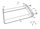
- FIG. 2 is a perspective view (part 1) of the clamp mechanism 130 according to the first embodiment of the present disclosure.
- FIG. 2 is a perspective view (part 2) of the clamp mechanism 130 according to the first embodiment of the present disclosure.
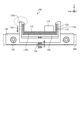
- FIG. 2 is a perspective view of a frame lock 120 according to a first embodiment of the present disclosure.
- FIG. 2 is an explanatory diagram (part 1) for explaining the installation position of the sensor device 100 according to the first embodiment of the present disclosure.
- FIG. 2 is an explanatory diagram (Part 2) for explaining the installation position of the sensor device 100 according to the first embodiment of the present disclosure.
- FIG. 2 is a bottom view of the main frame 110 according to the first embodiment of the present disclosure.
- FIG. 2 is a top view of main parts of the main frame 110 according to the first embodiment of the present disclosure.
- FIG. 2 is a side view (part 2) of main parts of the sensor device 100 according to the first embodiment of the present disclosure.
- FIG. 4 is a top view and a side view of a sensor device 200 according to a second embodiment of the present disclosure.
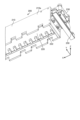
- FIG. 2 is a perspective view of main parts of a sensor device 200 according to a second embodiment of the present disclosure.
- FIG. 2 is a top view of main parts of a sensor device 200 according to a second embodiment of the present disclosure.
- FIG. 3 is a perspective view of an adjustment mechanism 230 according to a second embodiment of the present disclosure.
- FIG. 7 is a side view of an adjustment mechanism 230 according to a second embodiment of the present disclosure.
- FIG. 3 is a perspective view of a housing 210 according to a second embodiment of the present disclosure.
- FIG. 3 is an enlarged view of main parts of a housing 210 according to a second embodiment of the present disclosure.
- acoustic pianos grand pianos and upright pianos are referred to as acoustic pianos. Note that the embodiments of the present disclosure below will mainly be described using an example in which the present disclosure is applied to an acoustic piano, but the present embodiments are not limited to application to an acoustic piano, but may also be applied to an electronic piano. is possible.
- Patent Document 1 proposes a sensor device using a photoreflector sensor that can measure the amount of depression of each key without touching the keyboard of an acoustic piano.
- acoustic pianos are very delicate instruments, as evidenced by the need for periodic tuning, and the installation of the sensor devices described above requires drilling holes or applying excessive force. In this case, the tone of the piano may change.
- the position and width of the keyboard differs depending on the piano manufacturer or model, so the sensor devices that have been proposed so far are not suitable for each manufacturer's piano or model.
- This sensor device was developed as a special product. In other words, a highly versatile sensor device that can measure the amount of depression of each key depending on the position, width, etc. of the keyboard, which differs for each piano manufacturer or model, has not been proposed so far.
- the inventors of the present invention have developed an embodiment of a highly versatile sensor device that can be easily attached to and detached from pianos that do not have a sensing function at the time of shipment without any processing. I ended up creating it. More specifically, the present inventors have disclosed an embodiment of a non-contact type keyboard press amount sensor device placed under a piano keyboard, and a non-contact type keyboard press amount sensor placed on a piano keyboard. and created embodiments of the device. Hereinafter, details of these embodiments will be sequentially explained.
- FIG. 1 is a top view (upper part of FIG. 1) and a side view (lower part of FIG. 1) of a sensor device 100 according to the present embodiment.
- FIG. 2 is a perspective view of the main parts of the sensor device 100 according to the present embodiment
- FIG. 3 is a side view of the main parts of the sensor device 100 according to the present embodiment
- FIG. 1 is a top view (upper part of FIG. 1) and a side view (lower part of FIG. 1) of a sensor device 100 according to the present embodiment.
- FIGS. 5 and 6 are perspective views of the clamp mechanism 130 according to the present embodiment, and in detail, are views of the clamp mechanism 130 viewed from below.
- FIG. 7 is a perspective view of the frame lock 120 according to this embodiment.
- FIGS. 8 and 9 are explanatory diagrams for explaining the installation position of the sensor device 100 according to this embodiment.
- the sensor device 100 is installed inside a mechanism called an "action" of an acoustic piano.
- the action is a mechanism for transmitting the movements of the keyboard caused by the player's keystrokes to the hammers that strike the strings.
- a predetermined number for example, five
- structural members referred to as “action beams” or “beams” in this specification
- the sensor device 100 according to this embodiment is fixed to the beam by a clamp mechanism described later. Note that the number, position, and size (width, thickness) of the beams of an acoustic piano vary depending on the piano manufacturer and piano model.
- the sensor device 100 includes a plurality of sensors extending along the X-axis (longitudinal axis) direction and detecting the amount of depression of each key by reflection of light. It has a main frame (casing) 110 that accommodates a plurality of electronic circuit boards having photoreflector sensors. Further, as shown in the upper and lower rows of FIG. and a plurality of frame locks (connection mechanisms) 120 that connect the main frame 110 and the main frame 110.
- FIG. 1 shows an example of a sensor device 100 that corresponds to an acoustic piano having five beams 300. Specifically, in order to correspond to an acoustic piano having five beams 300, the sensor device 100 has five beams.
- the X axis refers to an axis along the direction in which each keyboard is arranged.
- the Y-axis refers to an axis that intersects perpendicularly to the X-axis on a plane consisting of a plurality of keyboards arranged side by side.In other words, it refers to an axis parallel to the long sides of a rectangular keyboard.
- the Z-axis refers to an axis along the vertical direction of the acoustic piano.
- the main frame 110 houses a plurality of electronic circuit boards 112.
- the main frame 110 includes a pair of side plates 110a that are parallel to a plane consisting of the X-axis and the Z-axis and extend along the X-axis direction;
- the bottom plate 110b is connected to the side plate 110a of the base plate 110a, and is parallel to the plane consisting of the X-axis and the Y-axis and extends along the X-axis direction.
- the main frame 110 has a substantially U-shaped cross section that opens upward (more specifically, a "U” in Japanese katakana), or a substantially U-shaped cross section that is bent at a right angle. It can be said to be a plate with a U-shaped cross section, with both ends bent at right angles.
- main frame 110 can be formed from a metal plate, for example.
- a plurality of electronic circuit boards 112 are installed on the bottom plate 110b of the main frame 110.
- an adjustment plate 150 may be installed between the bottom plate 110b of the main frame 110 and the electronic circuit board 112, and details of the adjustment plate 150 will be described later.
- Each electronic circuit board 112 is equipped with a plurality of photoreflector sensors 114, an electronic circuit for measurement, and electronic components (not shown).
- the electronic component may be an AD (analog-digital) converter that converts sensing data from the photoreflector sensor 114 into a digital signal.
- sensing data converted by an AD converter will be output to a computer installed outside the acoustic piano.
- each electronic circuit board 112 on each electronic circuit board 112, a plurality of photoreflector sensors 114 are arranged along the X-axis direction at predetermined intervals according to the position of each keyboard. Ru. More specifically, the sensor device 100 according to this embodiment is installed so that one photoreflector sensor 114 is located under each keyboard (white key or black key). Note that this embodiment has a mechanism that can adjust the position of each electronic circuit board 112 in the X-axis direction, and details of the adjustment mechanism will be described later.
- each photoreflector sensor 114 is composed of a pair of a light emitting element (not shown) that emits infrared light and a light receiving element (not shown) that receives the infrared light. More specifically, the light emitting element of the photoreflector sensor 114 is composed of, for example, an LED (Light Emitting Diode), and can emit light having a predetermined wavelength (for example, infrared light). On the other hand, the light receiving element of the photoreflector sensor 114 is made of, for example, a photodiode, and can generate a photocurrent (signal) depending on the amount of light received.
- the light emitting element of the photoreflector sensor 114 is composed of, for example, an LED (Light Emitting Diode), and can emit light having a predetermined wavelength (for example, infrared light).
- the light receiving element of the photoreflector sensor 114 is made of, for example, a photodiode, and can generate a photocurrent (
- a portion of the light emitted by the light emitting element is reflected by the lower surface of the keyboard, and is detected as reflected light by the light receiving element.
- the light receiving element changes. Therefore, according to the photoreflector sensor 114, the amount of light detected by the light receiving element changes depending on the amount of vertical movement of the keyboard, so the amount of movement of the keyboard is detected by the signal from the photoreflector sensor 114. It becomes possible to do so.
- the photoreflector sensor 114 has a temporal resolution of about 1 millisecond and a spatial resolution of about 0.01 mm, so it can detect changes over time in the amount of keyboard movement with high accuracy. More specifically, for example, the moment when the signal value of the photoreflector sensor 114 exceeds a predetermined threshold value can be regarded as the time when the keyboard starts moving (keystroke start time) (the time when the keyboard starts descending).
- the above threshold value can be set as appropriate in consideration of noise (white noise, etc.) and variations in the photoreflector sensor 114 itself. It is set to twice the standard deviation of the value, etc.
- the photoreflector sensor 114 can detect changes over time in the amount of keyboard movement with high accuracy, the photoreflector sensor 114 can detect not only the keystroke start time as described above but also the keystroke end time ( It is possible to detect the keystroke time (when the keyboard starts to rise), the keystroke time from the keystroke start time to the keystroke end time, etc. for each keyboard. Furthermore, according to the photoreflector sensor 114, it is possible to detect changes over time in keystroke speed (keyboard movement speed), acceleration (keyboard movement acceleration), movement amount, etc. for each keyboard. Note that this embodiment is not limited to using the photoreflector sensor 114, and may also use an optical sensor such as a ToF (Time of Flight) sensor that can measure the distance to the keyboard. good.
- ToF Time of Flight
- the sensor device 100 when fixing the sensor device 100 to an acoustic piano, do not drill holes in the acoustic piano or apply excessive force to the acoustic piano to apply a load that may distort the components of the acoustic piano. It is strongly required to avoid changes in the tone of the acoustic piano. Therefore, in the present embodiment, the sensor device 100 according to the present embodiment is inserted into the action mechanism of the acoustic piano by clamping each of the plurality of beams 300 located below the keyboard from the X-axis direction using the clamp mechanism 130. Fixed to. In this embodiment, by doing this, the sensor device 100 can be operated without processing the elements constituting the action mechanism, such as drilling holes, or applying excessive force. Since it is fixed within the action mechanism of the acoustic piano, changes in the tone of the acoustic piano can be avoided.
- each clamp mechanism 130 extends parallel to the plane consisting of the Y axis and the Z axis and along the Y axis direction.
- the upper surface portion 136 is composed of two planar plates extending along the X-axis direction.
- the frame member can be formed from a metal plate, for example.
- the clamp mechanism 130 is coupled to one side surface 134 and passes through a connecting member 142 on which the main frame 110 is placed and a plurality of holes (second hole portions) provided in the side surface 134. and a plurality of screws (second rod-shaped members) 132 that engage with grooves provided on the inner surface of the hole.
- the clamp mechanism 130 has two holes provided in the side part 134 and two screws 132, as shown in FIGS. 5 and 6, for example.
- the tip of each screw 132 includes, for example, a flat member 132a that contacts the side surface of the beam 300.
- the flat member 132a can be formed from a resin material.
- the upper surface portion 136 of the clamp mechanism 130 is placed on the beam 300. Furthermore, as shown in FIG. 2, by rotating the screw 132 and sandwiching the beam 300 between the other side surface portion 138 and the flat member 132a at the tip of the screw 132 along the X-axis direction, the beam 300 is The clamp mechanism 130, that is, the sensor device 100 can be fixed to the clamp mechanism 130, that is, the sensor device 100. In this embodiment, since the sensor device 100 is fixed to the action mechanism by sandwiching the beam 300 between the side surface portion 138 and the screw 132, it is not necessary to perform processing such as drilling holes in the elements constituting the action mechanism. There isn't.
- the beam 300 can be sandwiched between the side surface portion 138 and the screw 132 by rotating the screw 132 according to the width of the beam 300.
- the forces are balanced, and it is possible to avoid applying excessive force to the beam 300 of the action mechanism and causing the beam 300 to become distorted.
- the method is not limited to the screw 132, and instead of the screw 132, a spring, a lever, etc.
- the beam 300 may be fixed by sandwiching it using a biasing member.
- a biasing member is used, there is a possibility that force will be applied to the beam 300 unnecessarily, so it is preferable to use the screw 132 in this embodiment.
- a torque driver in order to pinch the beam 300 with a constant force.
- the number, position, and size of the beams 300 vary depending on the piano manufacturer and piano model. Therefore, in this embodiment, it is sufficient to prepare the number and size of clamp mechanisms 130 depending on the piano. Specifically, in this embodiment, a plurality of clamp mechanisms 130 may be prepared in a number corresponding to the number of beams 300 of the acoustic piano. Further, in this embodiment, for example, the above-described single clamp mechanism 130 can freely adjust the distance between the side surface portion 138 and the flat member 132a at the tip of the screw 132 from L1 to L2, as shown in FIG. can be changed to Therefore, in this embodiment, the clamping mechanism 130 can accommodate beams 300 having different widths. Furthermore, in this embodiment, if clamp mechanisms 130 of various sizes (for example, for 35 to 55 mm, 55 to 75 mm, and 75 to 95 mm) are prepared, It is possible to correspond to the beam 300.
- various sizes for example, for 35 to 55 mm, 55 to 75 mm, and 75 to 95 mm
- the frame lock 120 has a substantially U-shape that opens upward or a substantially U-shape that is bent at a right angle, and has a fixing member 122 that supports the main frame 110. has.
- the fixing member 122 can be made of, for example, a resin material. Further, the fixing member 122 has a protrusion 122a that is provided at the upper end of the fixing member 122, contacts the upper end of the side plate 110a of the main frame 110, and presses down the main frame 110.
- the frame lock 120 is inserted into the main frame 110 by penetrating through holes (first holes) provided in the bottom surfaces of the connecting member 142 and the fixing member 122 of the clamp mechanism 130. It has a screw (first rod-shaped member) 124 that pushes up the bottom plate 110b.
- the screw 124 may engage with a groove provided on the inner surface of the hole provided in the connecting member 142 and the fixing member 122.
- the tip of the screw 124 may be provided with a biasing member such as a spring, or may be provided with an elastic body such as a sponge-like member.
- the main frame 110 is placed inside the fixing member 122 of the frame lock 120.
- the fixing member 122 of the frame lock 120 and the connecting member 142 of the clamp mechanism 130 are fixed, and the bottom plate 110b of the main frame 110 is further pushed up.
- the upper end of the side plate 110a of the main frame 110 that has been pushed up comes into contact with the projection 122a of the fixing member 122 and is pushed down, thereby fixing the main frame 110.
- the main frame 110 is fixed to the beam 300.
- Frame 110 can be fixed. Therefore, according to the present embodiment, the sensor device 100 can be fixed without performing processing such as drilling holes in the elements constituting the action mechanism.
- the force for fixing the relative position of the clamp mechanism 130 and the main frame 110 is applied along the Z-axis direction by the frame lock 120. Since the beams 300 and the like are leaning against each other, no force is applied that could deform them.
- the relative positions of each are not limited and can be adjusted freely, so that the main frame 110 and the clamp mechanism 130 can be fixed without being influenced by the beam 300. It is possible to fix the clamp mechanism 130 and the main frame 110.
- the sensor device 100 can be fixed below the keyboard 302 and above the beam 300 in the action mechanism, as shown in FIGS. 8 and 9. .
- the sensor device 100 is fixedly installed by pulling out the action mechanism from the acoustic piano, attaching the clamp mechanism 130 to the beam 300 inside the action mechanism, and fixing the main frame 110 with the frame lock 120.
- the sensor device 100 is installed so that each keyboard 302 and each photoreflector sensor 114 are aligned, but the sensor device 100 (specifically, the electronic circuit board 112) is installed in the X-axis direction. The adjustment of the position will be described later.
- FIG. 10 is a bottom view of the main frame 110 according to the present embodiment
- FIG. 11 is a top view of main parts of the main frame 110 according to the present embodiment.
- the position, width, etc. of the keyboard 302 differ depending on the piano manufacturer or model. Therefore, in this embodiment, by providing a mechanism for adjusting the position of the electronic circuit board 112 in the X-axis direction, the positions of each keyboard 302 and each photoreflector sensor 114 are adjusted to match. By doing so, according to the present embodiment, it is possible to deal with keyboards 302 having different positions and widths.
- the main frame 110 of the sensor device 100 has a plurality of electronic circuit boards 112 arranged along the X-axis direction.
- the number of keys 302 for one octave is 12 keys (specifically, 7 white keys and 5 black keys). Therefore, in this embodiment, as shown in FIG. 11, 12 photoreflector sensors 114 are arranged along the X-axis direction at predetermined intervals so as to correspond to each of the 12 keyboards 302. Prepare the circuit board 112. Furthermore, in this embodiment, an electronic circuit board 112 is also prepared in which 16 photoreflector sensors 114 are arranged along the X-axis direction at predetermined intervals so as to correspond to each of the 16 keyboards 302.
- 12 photoreflector sensors 114 corresponding to one octave of keyboards 302 are provided on the electronic circuit board 112. It is not limited. For example, a plurality of photoreflector sensors 114 in numbers other than 12 or 16 may be provided on the electronic circuit board 112, and the number of electronic circuit boards 112 included in the main frame 110 may also be other than seven. may be used, and is not particularly limited.
- a long hole (long hole portion) 116 is formed in the bottom plate 110b of the main frame 110, passing through the bottom plate 110b and extending along the X-axis direction. is provided. Further, a hole passing through the electronic circuit board 112 is also provided on the electronic circuit board 112 side.
- each electronic circuit board 112 is fixed to the main frame 110 by being screwed by a screw 118 (first screw member) passing through the elongated hole 116 and the hole.
- the position of the electronic circuit board 112 in the X-axis direction can be adjusted by making one of the holes through which the screw 118 passes an elongated hole extending along the X-axis direction.
- the main frame 110 side is not limited to the elongated hole, and the electronic circuit board 112 side may be formed as the elongated hole.
- FIG. 12 is a side view of the main parts of the sensor device 100 according to this embodiment.
- one or more adjustment plates are provided between the electronic circuit board 112 and the main frame 110, as shown in FIG.
- an adjustment plate 150 may be provided.
- adjusting plates 150 having various thicknesses may be prepared. As described above, in this embodiment, by providing the adjustment plate 150 between the electronic circuit board 112 and the main frame 110, the distance between the lower surface of the keyboard 302 and the photoreflector sensor 114 can be adjusted appropriately. be able to.
- the sensor device 100 is fixed to the action mechanism by sandwiching the beam 300 between the side part 138 of the clamp mechanism 130 and the screw 132. Therefore, the elements constituting the action mechanism include: No drilling or other processing is required.
- the beam 300 can be sandwiched between the side surface portion 138 and the screw 132 by rotating the screw 132 according to the width of the beam 300, so that excessive force is not applied to the beam 300 of the action mechanism. can be avoided.
- the connecting member 142 of the clamp mechanism 130 and the main frame 110 are sandwiched between the fixing member 122 of the frame lock 120 along the Z-axis direction, so that the clamp mechanism 130 fixed to the beam 300 is On the other hand, the main frame 110 can be fixed.
- the sensor device 100 can be fixed without performing processing such as drilling holes in the elements constituting the action mechanism. Furthermore, in this embodiment, after each clamp mechanism 130 is attached to each beam 300, a force is applied to fix the relative position of the clamp mechanism 130 and the main frame 110 by the frame lock 120. No force is applied that could deform the beam 300 or the like. As a result, according to this embodiment, it is possible to avoid changes in the tone of the acoustic piano.
- the relative positions of each are not limited and can be adjusted freely, so that the main frame 110 and the clamp mechanism 130 can be fixed without being influenced by the beam 300. It is possible to fix the clamp mechanism 130 and the main frame 110.
- each of the plurality of electronic circuit boards 112 is screwed to the main frame 110 using elongated holes that are long in the X-axis direction, the position of the electronic circuit board 112 in the X-axis direction is It is possible to adjust. Therefore, according to this embodiment, it is possible to adjust the positions of each keyboard 302 and each photoreflector sensor 114 to match.
- by providing one or more adjustment plates 150 between the electronic circuit board 112 and the main frame 110 by providing one or more adjustment plates 150 between the electronic circuit board 112 and the main frame 110, the distance between the lower surface of the keyboard 302 and the photoreflector sensor 114 can be adjusted. can be adjusted appropriately.
- the sensor device 100 according to the present embodiment can be easily attached to and detached from an acoustic piano that does not have a sensing function at the time of shipment without any processing. Furthermore, the sensor device 100 can be compatible with various acoustic pianos. Note that the configuration of the sensor device 100 according to this embodiment is not limited to the configuration shown in the drawings.
- FIG. 13 is a top view (upper part of FIG. 13) and a side view (lower part of FIG. 13) of the sensor device 200 according to this embodiment.
- FIG. 14 is a perspective view of the main parts of the sensor device 200 according to the present embodiment
- FIG. 15 is a top view of the main parts of the sensor device 200 according to the present embodiment.
- FIG. 16 is a perspective view of the adjustment mechanism 230 according to this embodiment
- FIG. 17 is a side view of the adjustment mechanism 230 according to this embodiment.
- the sensor device 100 needs to be installed inside the action mechanism after pulling out the action mechanism from the piano, so it can be said that installation is troublesome.
- the sensor device 200 can be installed on the keyboard 302 of the piano, which is pressed by the player, so the sensor device 200 can be easily installed since there is no need to pull out the action mechanism.
- the second embodiment will be described using an example in which an acoustic piano is applied, but since the sensor device 200 of this embodiment can be installed on the keyboard 302, the application is limited to an acoustic piano. It can also be applied to electronic pianos.
- the sensor device 200 accommodates a plurality of electronic circuit boards 220 having a plurality of photoreflector sensors 222 that detect the amount of depression of each keyboard 302 by reflecting light. It has a casing 210 that blocks light from the outside.
- the sensor device 200 also includes a pair of fixing parts 250 that fix the housing 210 above each keyboard 302, and a pair of fixing parts 250 that adjust the position of the housing 210 along the Z-axis direction and the Y-axis direction. It has an adjustment mechanism 230.
- the casing 210 has a pair of side plates 210a that are parallel to a plane consisting of the Z-axis and the X-axis and extend along the X-axis. Furthermore, the housing 210 includes a frame member 210b that extends along the X-axis direction and is sandwiched between a pair of side plates 210a from the Y-axis direction.
- the housing 210 is formed from a resin material that can block light.
- the pair of side plates 210a are connected by the connecting members 270, 280, and the frame member 210b is sandwiched between the pair of side plates 210a.
- the end surface of the frame member 210b is provided with a plurality of holes (fifth hole portion) extending in the X-axis direction, and screws 236 (see FIG. 16) passing through the holes are provided. , is screwed to an adjustment mechanism 230, which will be described later.
- the housing 210 accommodates a plurality of electronic circuit boards 220 having a plurality of photoreflector sensors 222 inside thereof. Specifically, the plurality of electronic circuit boards 220 are fixed to the back surface of the frame member 210b of the housing 210.
- the electronic circuit board 220 is equipped with a plurality of photoreflector sensors 222, an electronic circuit for measurement, and electronic components (not shown). .
- a plurality of photoreflector sensors 222 are arranged on each electronic circuit board 220 along the X-axis direction at predetermined intervals in accordance with the position of each keyboard 302.
- the sensor device 200 according to this embodiment is installed so that one photoreflector sensor 222 is located above each keyboard (white keys and black keys) 302.
- this embodiment is not limited to using the photoreflector sensor 222, but may also use an optical sensor such as a ToF sensor that can measure the distance to the keyboard.
- the housing 210 of the sensor device 200 has a plurality of electronic circuit boards 220 arranged along the X-axis direction. Also in this embodiment, as shown in FIG. 15, an electronic circuit board is provided with 12 photoreflector sensors 222 arranged at predetermined intervals along the X-axis direction so as to correspond to each of the 12 keyboards 302. Prepare 220. Furthermore, in this embodiment as well, an electronic circuit board 220 is also prepared in which 16 photoreflector sensors 222 are arranged along the X-axis direction at predetermined intervals so as to correspond to each of the 16 keyboards 302.
- 12 photoreflector sensors 222 corresponding to one octave of keyboards 302 are provided on the electronic circuit board 220, but in this embodiment as well, such a form is used. It is not limited. For example, a plurality of photoreflector sensors 222 in numbers other than 12 or 16 may be provided on the electronic circuit board 220, and the number of electronic circuit boards 220 included in the housing 210 may also be other than seven. may be used, and is not particularly limited.
- this embodiment instead of one electronic circuit board 220 having a plurality of photoreflector sensors 222 that covers all 88 keys of the keyboard 302, a plurality of electronic circuit boards having a predetermined number of photoreflector sensors 222 are used. An electronic circuit board 220 is prepared. By doing so, this embodiment can also accommodate keyboards 302 with different positions and widths.
- the frame member 210b of the casing 210 is provided with a long hole (long hole portion) (not shown) that passes through the frame member 210b and is long along the X-axis direction. Good too.
- a hole passing through the electronic circuit board 220 may also be provided on the electronic circuit board 220 side.
- each electronic circuit board 220 is fixed to the housing 210 by being screwed by a screw (third screw member) (not shown) passing through the elongated hole and the hole. Ru.
- the hole is not limited to the case 210 side, and the electronic circuit board 220 side may be formed as a long hole.
- the pair of fixing parts 250 are provided so as to sandwich the housing 210 from the X-axis direction, and for example, as shown in the lower part of FIG. 13, FIGS.
- the sensor device 200 can be installed on the piano.
- the fixing part 250 in the space 304 beside the keyboard 302
- the sensor device 200 can be attached to a plurality of keys 302 without interfering with the movement of the keyboard 302 and without modifying the piano. It can be installed above.
- each fixing portion 250 has a substantially U-shape that opens upward, or a substantially U-shape that is bent at a right angle. Furthermore, each fixing part 250 supports a lower member 240 of the adjustment mechanism 230, which will be described later, via a shaft (third rod-shaped member) 246 sandwiched between both ends thereof. The fixing part 250 is connected to the adjustment mechanism 230 through the shaft 246 .
- the fixing part 250 is formed from a metal material, a resin material, or the like.
- Adjustment mechanism 230 In this embodiment, as in the first embodiment, it is important to accurately adjust the position of the photoreflector sensor 222 with respect to the keyboard 302 in order to achieve high measurement resolution, stable measurement, and versatility. It is. However, since the position and size of the keyboard 302 differ depending on each piano manufacturer and model, it is required to adjust the position of the photoreflector sensor 222 with high accuracy depending on each piano manufacturer and model. Therefore, in this embodiment, the adjustment mechanism 230 can adjust the position of the housing 210 (specifically, the electronic circuit board 220) in the Y-axis direction and the Z-axis direction.
- each adjustment mechanism 230 includes an upper member 232 coupled to the housing 210 and a lower member 240 located below the upper member.
- Adjustment mechanism 230 is made of, for example, a metal material.
- the upper member 232 engages with a hole (third hole) that passes through the upper member 232 along the Z-axis direction and a groove provided on the inner surface of the hole, and has a distal end that is connected to the lower member. 240 and a screw (second screw member) 234 fixed to the upper surface of the screw. Further, the end surfaces of the upper member 232 and the frame member 210b of the housing 210 are provided with a plurality of holes (fifth and sixth holes) extending in the X-axis direction, and screws (third rod-shaped They are screwed and connected to each other by a member) 236.
- the upper member 232 can be moved in the Z-axis direction, and accordingly, the frame member 210b of the housing 210 is also moved in the Z-axis direction. Therefore, in this embodiment, the Z-axis direction (height direction) of the housing 210, that is, the distance between the keyboard 302 and the photoreflector sensor 222 can be adjusted with high precision.
- the lower member 240 also has a hole (fourth hole) (not shown) that passes through the lower member 240 along the Y-axis direction, and is sandwiched between the hole and the fixing part 250. It has a shaft 246.
- the upper member 232 also moves along the Y-axis direction.
- the housing 210 specifically, the electronic circuit board 220
- the measurement resolution can be adjusted by adjusting the position of the photoreflector sensor 222 on the electronic circuit board 220 in the Y-axis direction.
- the resolution of the photoreflector sensor 222 will be higher if the sensor device 200 is installed so that the photoreflector sensor 222 is located in front of the player. However, if the sensor device 200 is installed closer to the performer, it will interfere with the performance. Therefore, in this embodiment, it is preferable to adjust the position of the sensor device 200 in the Y-axis direction depending on the piano and the player.
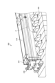
- FIG. 18 is a perspective view of the casing 210 according to the present embodiment
- FIG. 19 is an enlarged view of main parts of the casing 210 according to the present embodiment, which are surrounded by a broken line circle A in FIG. 18. It is an enlarged view of the main part.
- the photoreflector sensor 222 measures the amount of infrared light emitted from the light emitting element of the photoreflector sensor 222 by reflecting it on the top surface of the keyboard 302 and reflecting by the light receiving element of the photoreflector sensor 222. In this way, the amount of depression of the keyboard 302 is measured.
- infrared light is also included in sunlight and light from incandescent light bulbs
- the infrared light component environment light from the external environment other than the light emitting element of the photoreflector sensor 222 itself is transmitted to the photoreflector sensor 222. There is a concern that this may adversely affect the measurement of the light receiving element of 222.
- a housing 210 is provided to block the above-mentioned environmental light. That is, although the housing 210 covers the photoreflector sensor 222 facing the keyboard 302, the movement of the keyboard 302 must not be hindered by the covering. Therefore, in this embodiment, a plurality of recesses 210c (Fig. 19)).
- the lower end of the player side side plate 210a of the housing 210 has a plurality of recesses 210c arranged at predetermined intervals along the X-axis direction.
- the plurality of recesses 210c engage with the plurality of black keys 302b that protrude upward compared to the white key 302a with a predetermined gap.
- the gap be as narrow as possible. Therefore, in this embodiment, the gap is adjusted with high accuracy by adjusting the position of the housing 210 in the Z-axis direction using the adjustment mechanism 230 described above.
- the adjustment mechanism 230 can adjust the gap to several millimeters or less.
- the sensor device 200 can be installed on the keyboard 302 of the piano that is pressed by the player, and therefore the action mechanism does not need to be pulled out, so the sensor device 200 can be easily installed. can do. Furthermore, in this embodiment, by installing the fixing part 250 in the space 304 beside the keyboard 302, the sensor device 200 can be connected to multiple sensor devices without interfering with the movement of the keyboard 302 and without modifying the piano. It can be installed above the keyboard 302. As a result, according to this embodiment, it is possible to avoid changes in the tone of an acoustic piano, for example.
- each of the plurality of electronic circuit boards 220 is screwed to the housing 210 using elongated holes long in the X-axis direction, the position of the electronic circuit board 220 in the X-axis direction is It is possible to adjust. Therefore, according to this embodiment, it is possible to adjust the positions of each keyboard 302 and each photoreflector sensor 222 to match.
- the adjustment mechanism 230 can adjust the position of the housing 210 (specifically, the electronic circuit board 220) in the Y-axis direction and the Z-axis direction, the position of the keyboard 302 can be adjusted. The position of the photoreflector sensor 222 with respect to the keyboard 302 can be adjusted with high accuracy even if the keyboard 302 is different in size or size.
- the sensor device 200 can be easily attached to and detached from a piano that does not have a sensing function at the time of shipment without any processing. Furthermore, the sensor device 200 can be compatible with various pianos. Note that the configuration of the sensor device 200 according to this embodiment is not limited to the configuration shown in the drawings.
- a highly versatile sensor device (keyboard press amount sensor device ) 100, 200 can be provided.
- a keyboard press amount sensor device that is installed below each keyboard of a piano arranged along a longitudinal axis and detects the press amount of each of the keys, an electronic circuit board having a plurality of optical sensors that detect the amount of depression of each of the keys by reflecting light; a casing extending along the longitudinal axis and accommodating the electronic circuit board; a clamp mechanism that clamps action beams located below the keyboard from the longitudinal axis direction; a connection mechanism that connects the clamp mechanism and the casing; Equipped with The casing is a pair of side plates extending along the longitudinal axis; a bottom plate that supports the electronic circuit board and is coupled to the pair of side plates and extends along the longitudinal axis; has The connection mechanism is a fixing member that supports the casing; a first rod-shaped member that penetrates a first hole provided in the bottom of the fixing member and pushes up the bottom plate of the casing; a protrusion provided on the fixing member that contacts the upper end of the side plate of the
- the keyboard press amount sensor device (2) The keyboard press amount sensor device according to (1) above, wherein the first rod-shaped member is a screw that engages with a groove inside the first hole. (3) The keyboard press amount sensor device according to (2) above, wherein a biasing member or an elastic body is provided at the tip of the first rod-shaped member. (4) The fixing member of the connection mechanism has a substantially U-shaped cross section that opens upward; The keyboard press amount sensor device according to any one of (1) to (3) above, wherein the protrusion is provided at the upper end of the fixing member. (5) The keyboard press amount sensor device according to any one of (1) to (4) above, wherein the second rod-shaped member is a screw that engages with a groove inside the second hole.
- the electronic circuit board is arranged along the longitudinal axis and fixed to the bottom plate of the casing by being screwed with a first screw member, The first screw member passes through a long hole provided in the bottom plate of the electronic circuit board or the housing and that is long along the longitudinal axis.
- the keyboard press amount sensor device according to any one of (1) to (8) above. (10) further comprising a height adjustment plate installed between the electronic circuit board and the casing; The keyboard press amount sensor device according to any one of (1) to (9) above.
- a keyboard press amount sensor device that is installed above each keyboard of a piano arranged along a longitudinal axis and detects the press amount of each of the keys, the device comprising: an electronic circuit board having a plurality of optical sensors that detect the amount of depression of each of the keys by reflecting light; a casing that houses the electronic circuit board and blocks light from the outside; a pair of fixing parts that fix the housing above each of the keyboards; a pair of adjustment mechanisms that adjust the position of the housing in the vertical direction and along the transverse axis direction perpendicular to the longitudinal axis in a horizontally expanding plane; Equipped with Each of the fixing parts has a substantially U-shaped shape that opens upward, and supports the adjustment mechanism via a third rod-shaped member sandwiched between the fixing parts, Each of the adjustment mechanisms is an upper member connected to the casing; a lower member located below the upper member; has The upper member is a third hole that passes through the upper member in the vertical direction; a second screw member that engages with a groove provided on the inner surface of the third
- the casing is a pair of side plates extending along the longitudinal axis; a frame member sandwiched between the pair of side plates and extending along the longitudinal axis; has, The keyboard press amount sensor device according to (11) above.
- the lower end of one side plate of the housing has a plurality of recesses arranged along the longitudinal axis at predetermined intervals, The plurality of recesses engage with the plurality of black keys with a predetermined gap, The keyboard press amount sensor device according to (12) or (13) above.
- the electronic circuit board is arranged along the longitudinal axis and is fixed to the frame member of the casing by being screwed with a third screw member, The third screw member passes through a long hole portion provided in the frame member of the electronic circuit board or the housing and that is long along the longitudinal axis.
- the keyboard press amount sensor device according to any one of (12) to (14) above.
- the optical sensor is a photoreflector sensor.
- the keyboard press amount sensor device according to any one of (1) to (17) above, wherein the plurality of optical sensors are arranged on the electronic circuit board at predetermined intervals along the longitudinal axis. .
Abstract
This keyboard pushdown amount sensor device (100) is installed below each of piano keyboards provided side by side along a longitudinal axis and detects the pushdown amount of each of the keyboards, the keyboard pushdown amount sensor device comprising: an electronic circuit board (112) having a plurality of optical sensors that detect the pushdown amount of each of the keyboards by means of light reflection; a housing (110) which extends along the longitudinal axis and accommodates the electronic circuit board; a clamp mechanism (130) which clamps each of action beams (300) located below the keyboards in the longitudinal axis direction; and a connection mechanism (120) which connects the clamp mechanism and the housing.
Description
本開示は、鍵盤押下量センサデバイスに関する。
The present disclosure relates to a keyboard press amount sensor device.
近年、容易に使用することができる各種センサが開発されたことにより、アコースティックピアノ等のピアノの演奏における様々な動作をセンシングして、その結果をフィードバック等することにより、演奏の習得支援等に役立てる試みが盛んに行われるようになった。例えば、下記特許文献1では、アコースティックピアノの鍵盤に接触することなく各鍵盤の押下量を計測することが可能なセンサデバイスが提案されている。
In recent years, with the development of various sensors that are easy to use, it is possible to sense the various movements of a piano such as an acoustic piano, and provide feedback on the results, which can be used to assist in learning to play. Many attempts have been made. For example, Patent Document 1 below proposes a sensor device that can measure the amount of depression of each key of an acoustic piano without touching the keyboard.
しかしながら、アコースティックピアノは、定期的な調律が必要なことからも明らかなように、繊細な楽器であり、例えば加工を施してセンサデバイスを取り付けた場合、アコースティックピアノの音色が変化してしまう恐れがある。また、アコースティックピアノや電子ピアノにおいては、ピアノメーカーごとに、鍵盤の位置やその幅等が異なることから、これまで提案されてきたセンサデバイスは、各ピアノに対して専用品として開発されたセンサデバイスであった。
However, acoustic pianos are delicate instruments, as is clear from the fact that they require periodic tuning.For example, if a sensor device is installed after being processed, there is a risk that the tone of the acoustic piano may change. be. In addition, in acoustic pianos and digital pianos, the position and width of the keyboard differs depending on the piano manufacturer, so the sensor devices that have been proposed so far are sensor devices developed specifically for each piano. Met.
そこで、本開示では、出荷時にセンシング機能を持たないピアノに、加工を施すことなく容易に着脱可能であり、且つ、汎用性の高い鍵盤押下量センサデバイスを提案する。
Therefore, the present disclosure proposes a highly versatile keyboard press amount sensor device that can be easily attached to and detached from a piano that does not have a sensing function at the time of shipment without any processing.
本開示によれば、長手軸に沿って並ぶピアノの各鍵盤の下方に設置され、前記各鍵盤の押下量を検出する鍵盤押下量センサデバイスであって、前記各鍵盤の押下量を光の反射で検出する複数の光学式センサを有する電子回路基板と、前記長手軸に沿って延伸し、前記電子回路基板を収容する筐体と、前記鍵盤の下方に位置するアクション梁を前記長手軸方向からそれぞれ挟み込むクランプ機構と、前記クランプ機構と前記筐体とを接続する接続機構とを備え、前記筐体は、前記長手軸方向に沿って延伸する一対の側面板と、前記一対の側面板と結合し、且つ、前記長手軸に沿って延伸する、前記電子回路基板を支持する底面板とを有し、前記接続機構は、前記筐体を支持する固定部材と、前記固定部材の底面に設けられた第1の穴部に貫通して、前記筐体の前記底面板を上方に押し上げる第1の棒状部材と、前記固定部材に設けられ、前記筐体の前記側面板の上端と接触して前記筐体を押し下げる突起部とを有し、前記クランプ機構は、上下方向に沿って延伸する一対の側面部、及び、前記一対の側面部と結合し、且つ、水平面と平行な上面部から構成されるフレーム部材と、一方の前記側面部と結合し、前記固定部材と前記底面板との間に挟まれる接続部材と、前記一方の側面部に設けられた第2の穴部を貫通し、前記第2の穴部の内側面に設けられた溝に係合する第2の棒状部材とを有し、前記上面部は、前記アクション梁上に載置され、他方の前記側面部と前記第2の棒状部材の先端部とで前記アクション梁を挟み込むことで、前記アクション梁上に前記筐体を固定する、鍵盤押下量センサデバイスが提供される。
According to the present disclosure, there is provided a keyboard press amount sensor device that is installed below each keyboard of a piano arranged along a longitudinal axis and detects the press amount of each of the keys, and the keyboard press amount sensor device detects the press amount of each of the keys by reflecting light. an electronic circuit board having a plurality of optical sensors for detection, a casing extending along the longitudinal axis and accommodating the electronic circuit board, and an action beam located below the keyboard from the longitudinal axis direction; The housing includes a clamp mechanism that clamps the clamp mechanism and a connection mechanism that connects the clamp mechanism and the housing, and the housing is coupled to a pair of side plates extending along the longitudinal axis direction and the pair of side plates. and a bottom plate that supports the electronic circuit board and extends along the longitudinal axis, and the connection mechanism includes a fixing member that supports the casing, and a bottom plate of the fixing member. a first rod-shaped member that penetrates the first hole and pushes up the bottom plate of the housing; The clamp mechanism has a protrusion that pushes down the housing, and the clamp mechanism includes a pair of side parts extending in the vertical direction, and an upper part coupled to the pair of side parts and parallel to the horizontal plane. a frame member that is coupled to one of the side surfaces and is sandwiched between the fixing member and the bottom plate; a second rod-shaped member that engages with a groove provided on the inner surface of the second hole, the upper surface portion is placed on the action beam, and the other side surface portion and the second A keyboard press amount sensor device is provided in which the housing is fixed onto the action beam by sandwiching the action beam between the tip of a rod-like member.
また、本開示によれば、長手軸に沿って並ぶピアノの各鍵盤の上方に設置され、前記各鍵盤の押下量を検出する鍵盤押下量センサデバイスであって、前記各鍵盤の押下量を光の反射で検出する複数の光学式センサを有する電子回路基板と、前記電子回路基板を収容し、外部からの光を遮蔽する筐体と、前記筐体を前記各鍵盤の上方に固定する一対の固定部と、上下方向、及び、水平に広がる平面において前記長手軸と垂直に交わる短手軸方向に沿って、前記筐体の位置を調整する一対の調整機構とを備え、前記各固定部は、上方に向かって開いた略コの字型形状を有し、且つ、前記固定部に挟まれた第3の棒状部材を介して前記調整機構を支持し、前記各調整機構は、前記筐体と接続する上部部材と、前記上部部材の下方に位置する下部部材とを有し、前記上部部材は、当該上部部材を上下方向に沿って貫通する第3の穴部と、前記第3の穴部の内側面に設けられた溝に係合し、且つ、一方の端部が前記下部部材の上面と接続する第2のねじ部材とを有し、前記下部部材は、前記短手軸に沿って、前記下部部材を貫通する第4の穴部と、前記第4の穴部を貫通し、且つ、前記固定部の内側に挟まれる前記第3の棒状部材とを有する、鍵盤押下量センサデバイスが提供される。
Further, according to the present disclosure, there is provided a keyboard press amount sensor device that is installed above each keyboard of a piano arranged along a longitudinal axis and detects a press amount of each of the keys, the device detects the press amount of each of the keys, and the device detects the press amount of each of the keys. an electronic circuit board having a plurality of optical sensors that detect by reflection of the electronic circuit board; a housing that houses the electronic circuit board and blocks light from the outside; and a pair of electronic circuit boards that fix the housing above each of the keyboards. and a pair of adjustment mechanisms that adjust the position of the housing in the vertical direction and along the transverse axis direction perpendicular to the longitudinal axis in a horizontally expanding plane, each of the fixing parts , has a substantially U-shaped shape that opens upward, and supports the adjustment mechanism via a third rod-shaped member sandwiched between the fixing portions, and each adjustment mechanism is connected to the housing. and a lower member located below the upper member, the upper member having a third hole passing through the upper member in the vertical direction, and a third hole extending through the upper member in the vertical direction. a second threaded member that engages with a groove provided on an inner surface of the lower member and has one end connected to the upper surface of the lower member, the lower member having a second threaded member that extends along the transverse axis; a keyboard press amount sensor device, comprising: a fourth hole passing through the lower member; and the third rod-shaped member passing through the fourth hole and sandwiched inside the fixing part. is provided.
以下に、添付図面を参照しながら、本開示の好適な実施の形態について詳細に説明する。なお、本明細書及び図面において、実質的に同一の機能構成を有する構成要素については、同一の符号を付することにより重複説明を省略する。
Hereinafter, preferred embodiments of the present disclosure will be described in detail with reference to the accompanying drawings. Note that, in this specification and the drawings, components having substantially the same functional configurations are designated by the same reference numerals and redundant explanation will be omitted.
また、以下の説明で参照される図面は、本開示の一実施形態の説明とその理解を促すための図面であり、わかりやすくするために、図中に示される形状や寸法、比などは実際と異なる場合がある。また、同様に、一部の図示を省略する場合がある。さらに、図中に示されるセンサデバイスは、以下の説明と公知の技術を参酌して適宜、設計変更することができる。
In addition, the drawings referred to in the following explanation are drawings for explaining one embodiment of the present disclosure and promoting understanding thereof, and for the sake of clarity, the shapes, dimensions, ratios, etc. shown in the drawings are not actual. It may be different. Similarly, some illustrations may be omitted. Furthermore, the design of the sensor device shown in the drawings can be changed as appropriate with reference to the following explanation and known techniques.
なお、本明細書においては、グランドピアノ、アップライトピアノのことを、アコースティックピアノと称するものとする。なお、以下の本開示の実施形態は、主に、アコースティックピアノ適用した場合を例に説明するが、本実施形態は、アコースティックピアノへの適用に限定されるものではなく、電子ピアノに適用することが可能である。
Note that in this specification, grand pianos and upright pianos are referred to as acoustic pianos. Note that the embodiments of the present disclosure below will mainly be described using an example in which the present disclosure is applied to an acoustic piano, but the present embodiments are not limited to application to an acoustic piano, but may also be applied to an electronic piano. is possible.
なお、説明は以下の順序で行うものとする。
1. 本開示の実施形態を創作するに至る背景
2. 第1の実施形態
2.1 詳細構成
2.2 電子回路基板の調整
2.3 高さ調整
3. 第2の実施形態
3.1 詳細構成
3.2 遮光機能
4. まとめ
5. 補足 Note that the explanation will be given in the following order.
1. Background to the creation of the embodiments of the present disclosure 2. First embodiment 2.1 Detailed configuration 2.2 Adjustment of electronic circuit board 2.3 Height adjustment 3. Second embodiment 3.1 Detailed configuration 3.2 Light shielding function 4. Summary 5. supplement
<<1. 本開示の実施形態を創作するに至る背景>>
まずは、本開示の実施形態を説明する前に、本発明者らが本開示の実施形態を創作するに至る背景について説明する。 <<1. Background leading to the creation of the embodiments of the present disclosure >>
First, before describing the embodiments of the present disclosure, the background that led the present inventors to create the embodiments of the present disclosure will be explained.
先に説明したように、近年、容易に使用することができる各種センサが開発されたことにより、例えばアコースティックピアノ(詳細には、グランドピアノ、アップライトピアノ)の演奏における様々な動作をセンシングして、その結果をフィードバック等することにより、演奏の習得支援等に役立てる試みが盛んに行われるようになった。例えば、上記特許文献1では、アコースティックピアノの鍵盤に接触することなく各鍵盤の押下量を計測することが可能な、フォトリフレクターセンサを使用したセンサデバイスが提案されている。
As explained above, in recent years, various types of sensors that can be easily used have been developed, which makes it possible to sense various movements during the performance of, for example, an acoustic piano (specifically, a grand piano or an upright piano). Many attempts have been made to provide feedback on the results to assist in learning to play. For example, the above-mentioned Patent Document 1 proposes a sensor device using a photoreflector sensor that can measure the amount of depression of each key without touching the keyboard of an acoustic piano.
しかしながら、アコースティックピアノは、定期的な調律が必要なことからも明らかなように、非常に繊細な楽器であり、穴をあけたり、過剰に力を印加したりして、上記センサデバイスを取り付けた場合、ピアノの音色が変化してしまう恐れがある。また、アコースティックピアノや電子ピアノにおいては、ピアノメーカーごと、又は、機種ごとに、鍵盤の位置やその幅等が異なることから、これまで提案されていたセンサデバイスは、各メーカーのピアノ又は機種に対して専用品として開発されたセンサデバイスであった。言い換えると、ピアノメーカーごと又は機種ごとに異なる鍵盤の位置や幅等に応じて、各鍵盤の押下量を計測することが可能な、汎用性の高いセンサデバイスは、これまで提案されていなかった。
However, acoustic pianos are very delicate instruments, as evidenced by the need for periodic tuning, and the installation of the sensor devices described above requires drilling holes or applying excessive force. In this case, the tone of the piano may change. Furthermore, in acoustic pianos and electronic pianos, the position and width of the keyboard differs depending on the piano manufacturer or model, so the sensor devices that have been proposed so far are not suitable for each manufacturer's piano or model. This sensor device was developed as a special product. In other words, a highly versatile sensor device that can measure the amount of depression of each key depending on the position, width, etc. of the keyboard, which differs for each piano manufacturer or model, has not been proposed so far.
そこで、本発明者らは、このような状況を鑑みて、出荷時にセンシング機能を持たないピアノに、加工等を施すことなく容易に着脱可能で、且つ、汎用性の高いセンサデバイスの実施形態を創作するに至った。より具体的には、本発明者らは、ピアノの鍵盤下に配置される非接触型の鍵盤押下量センサデバイスの実施形態と、ピアノの鍵盤上に配置される非接触型の鍵盤押下量センサデバイスの実施形態とを創作した。以下、これら実施形態の詳細を順次説明する。
In view of this situation, the inventors of the present invention have developed an embodiment of a highly versatile sensor device that can be easily attached to and detached from pianos that do not have a sensing function at the time of shipment without any processing. I ended up creating it. More specifically, the present inventors have disclosed an embodiment of a non-contact type keyboard press amount sensor device placed under a piano keyboard, and a non-contact type keyboard press amount sensor placed on a piano keyboard. and created embodiments of the device. Hereinafter, details of these embodiments will be sequentially explained.
<<2. 第1の実施形態>>
<2.1 詳細構成>
まずは、本開示の第1の実施形態として、アコースティックピアノの各鍵盤の下方に設置され、各鍵盤の押下量を検出するセンサデバイス(鍵盤押下量センサデバイス)について説明する。図1から図9を参照して、本実施形態のセンサデバイス100の詳細構成を説明する。図1は、本実施形態に係るセンサデバイス100の上面図(図1上段)及び側面図(図1下段)である。また、図2は、本実施形態に係るセンサデバイス100の要部の斜視図であり、図3は、本実施形態に係るセンサデバイス100の要部の側面図であり、図4は、本実施形態に係るセンサデバイス100の要部の上面図である。また、図5及び図6は、本開実施形態に係るクランプ機構130の斜視図であり、詳細には、クランプ機構130を下方から見た場合の図である。また、図7は、本実施形態に係るフレームロック120の斜視図である。さらに、図8及び図9は、本実施形態に係るセンサデバイス100の設置位置を説明するための説明図である。 <<2. First embodiment >>
<2.1 Detailed configuration>
First, as a first embodiment of the present disclosure, a sensor device (keyboard press amount sensor device) that is installed below each keyboard of an acoustic piano and detects the press amount of each key will be described. The detailed configuration of thesensor device 100 of this embodiment will be described with reference to FIGS. 1 to 9. FIG. 1 is a top view (upper part of FIG. 1) and a side view (lower part of FIG. 1) of a sensor device 100 according to the present embodiment. 2 is a perspective view of the main parts of the sensor device 100 according to the present embodiment, FIG. 3 is a side view of the main parts of the sensor device 100 according to the present embodiment, and FIG. 4 is a perspective view of the main parts of the sensor device 100 according to the present embodiment. It is a top view of the principal part of sensor device 100 concerning this embodiment. Moreover, FIGS. 5 and 6 are perspective views of the clamp mechanism 130 according to the present embodiment, and in detail, are views of the clamp mechanism 130 viewed from below. Moreover, FIG. 7 is a perspective view of the frame lock 120 according to this embodiment. Furthermore, FIGS. 8 and 9 are explanatory diagrams for explaining the installation position of the sensor device 100 according to this embodiment.
<2.1 詳細構成>
まずは、本開示の第1の実施形態として、アコースティックピアノの各鍵盤の下方に設置され、各鍵盤の押下量を検出するセンサデバイス(鍵盤押下量センサデバイス)について説明する。図1から図9を参照して、本実施形態のセンサデバイス100の詳細構成を説明する。図1は、本実施形態に係るセンサデバイス100の上面図(図1上段)及び側面図(図1下段)である。また、図2は、本実施形態に係るセンサデバイス100の要部の斜視図であり、図3は、本実施形態に係るセンサデバイス100の要部の側面図であり、図4は、本実施形態に係るセンサデバイス100の要部の上面図である。また、図5及び図6は、本開実施形態に係るクランプ機構130の斜視図であり、詳細には、クランプ機構130を下方から見た場合の図である。また、図7は、本実施形態に係るフレームロック120の斜視図である。さらに、図8及び図9は、本実施形態に係るセンサデバイス100の設置位置を説明するための説明図である。 <<2. First embodiment >>
<2.1 Detailed configuration>
First, as a first embodiment of the present disclosure, a sensor device (keyboard press amount sensor device) that is installed below each keyboard of an acoustic piano and detects the press amount of each key will be described. The detailed configuration of the
本実施形態に係るセンサデバイス100は、アコースティックピアノの「アクション」と呼ばれる機構の内部に設置される。当該アクションは、演奏者の打鍵による鍵盤の動きを、弦を打つハンマーに伝えるための機構である。当該アクションの内部においては、鍵盤の下方に、所定の数(例えば、5本)の構造部材(本明細書においては、「アクション梁」、又は、「梁」と称する)が設けられており、本実施形態に係るセンサデバイス100は、後述するクランプ機構により、当該梁に固定されることとなる。なお、アコースティックピアノの梁の本数、位置、サイズ(幅、厚み)については、ピアノメーカーごと、ピアノ機種ごとに異なる。
The sensor device 100 according to this embodiment is installed inside a mechanism called an "action" of an acoustic piano. The action is a mechanism for transmitting the movements of the keyboard caused by the player's keystrokes to the hammers that strike the strings. Inside the action, a predetermined number (for example, five) of structural members (referred to as "action beams" or "beams" in this specification) are provided below the keyboard, The sensor device 100 according to this embodiment is fixed to the beam by a clamp mechanism described later. Note that the number, position, and size (width, thickness) of the beams of an acoustic piano vary depending on the piano manufacturer and piano model.
詳細には、本実施形態に係るセンサデバイス100は、図1の上段に示すように、X軸(長手軸)方向に沿って延伸し、各鍵盤の押下量を光の反射で検出する複数のフォトリフレクターセンサを有する複数の電子回路基板を収容するメインフレーム(筐体)110を有する。また、当該センサデバイス100は、図1の上段及び下段に示すように、鍵盤の下方に位置する複数の梁300のそれぞれをX軸方向からそれぞれ挟み込む複数のクランプ機構130と、当該各クランプ機構130とメインフレーム110とを接続する複数のフレームロック(接続機構)120とを有する。図1は、5本の梁300を持つアコースティックピアノに対応するセンサデバイス100の例を示し、詳細には、5本の梁300を持つアコースティックピアノに対応するため、当該センサデバイス100は、5つのクランプ機構130と5つのフレームロック120とを有している。なお、本実施形態においては、クランプ機構130及びフレームロック120の数は特に限定されるものではない。また、本明細書、及び、本明細書に添付の図面においては、X軸は、各鍵盤が並ぶ方向に沿った軸のことをいう。また、Y軸は、並ぶ複数の鍵盤からなる平面において、上記X軸と垂直に交わる軸のことをいい、言い換えると、長方形の鍵盤の長辺に対して平行な軸のことをいう。さらに、Z軸は、アコースティックピアノの上下方向に沿った軸のことをいう。以下、本実施形態に係るセンサデバイス100の各要素の詳細を順次説明する。
Specifically, as shown in the upper part of FIG. 1, the sensor device 100 according to the present embodiment includes a plurality of sensors extending along the X-axis (longitudinal axis) direction and detecting the amount of depression of each key by reflection of light. It has a main frame (casing) 110 that accommodates a plurality of electronic circuit boards having photoreflector sensors. Further, as shown in the upper and lower rows of FIG. and a plurality of frame locks (connection mechanisms) 120 that connect the main frame 110 and the main frame 110. FIG. 1 shows an example of a sensor device 100 that corresponds to an acoustic piano having five beams 300. Specifically, in order to correspond to an acoustic piano having five beams 300, the sensor device 100 has five beams. It has a clamp mechanism 130 and five frame locks 120. Note that in this embodiment, the number of clamp mechanisms 130 and frame locks 120 is not particularly limited. Furthermore, in this specification and the drawings attached to this specification, the X axis refers to an axis along the direction in which each keyboard is arranged. In addition, the Y-axis refers to an axis that intersects perpendicularly to the X-axis on a plane consisting of a plurality of keyboards arranged side by side.In other words, it refers to an axis parallel to the long sides of a rectangular keyboard. Furthermore, the Z-axis refers to an axis along the vertical direction of the acoustic piano. Hereinafter, details of each element of the sensor device 100 according to this embodiment will be sequentially explained.
(メインフレーム110)
図2、図3及び図4に示すように、メインフレーム110は、複数の電子回路基板112を収容する。具体的には、メインフレーム110は、図2及び図3に示すように、X軸及びZ軸からなる平面に平行で、且つ、X軸方向に沿って延伸する一対の側面板110aと、一対の側面板110aと結合し、X軸及びY軸からなる平面に平行で、且つ、X軸方向に沿って延伸する底面板110bとから構成される。詳細には、メインフレーム110は、図3に示すように、上方に向かって開いた略コの字(詳細には、日本語のカタカナの「コ」)型断面、もしくは、直角に屈曲した略U字型断面を持つ、両端を直角に曲げられた板であるといえる。例えば、メインフレーム110は、例えば、金属板から形成することができる。 (Mainframe 110)
As shown in FIGS. 2, 3, and 4, themain frame 110 houses a plurality of electronic circuit boards 112. Specifically, as shown in FIGS. 2 and 3, the main frame 110 includes a pair of side plates 110a that are parallel to a plane consisting of the X-axis and the Z-axis and extend along the X-axis direction; The bottom plate 110b is connected to the side plate 110a of the base plate 110a, and is parallel to the plane consisting of the X-axis and the Y-axis and extends along the X-axis direction. Specifically, as shown in FIG. 3, the main frame 110 has a substantially U-shaped cross section that opens upward (more specifically, a "U" in Japanese katakana), or a substantially U-shaped cross section that is bent at a right angle. It can be said to be a plate with a U-shaped cross section, with both ends bent at right angles. For example, main frame 110 can be formed from a metal plate, for example.
図2、図3及び図4に示すように、メインフレーム110は、複数の電子回路基板112を収容する。具体的には、メインフレーム110は、図2及び図3に示すように、X軸及びZ軸からなる平面に平行で、且つ、X軸方向に沿って延伸する一対の側面板110aと、一対の側面板110aと結合し、X軸及びY軸からなる平面に平行で、且つ、X軸方向に沿って延伸する底面板110bとから構成される。詳細には、メインフレーム110は、図3に示すように、上方に向かって開いた略コの字(詳細には、日本語のカタカナの「コ」)型断面、もしくは、直角に屈曲した略U字型断面を持つ、両端を直角に曲げられた板であるといえる。例えば、メインフレーム110は、例えば、金属板から形成することができる。 (Mainframe 110)
As shown in FIGS. 2, 3, and 4, the
また、図2、図3及び図4に示すように、メインフレーム110の底面板110b上に、複数の各電子回路基板112が設置される。なお、本実施形態においては、メインフレーム110の底面板110bと電子回路基板112との間には、調整板150が設置されてもよく、当該調整板150の詳細については、後述する。
Further, as shown in FIGS. 2, 3, and 4, a plurality of electronic circuit boards 112 are installed on the bottom plate 110b of the main frame 110. In this embodiment, an adjustment plate 150 may be installed between the bottom plate 110b of the main frame 110 and the electronic circuit board 112, and details of the adjustment plate 150 will be described later.
各電子回路基板112には、複数のフォトリフレクターセンサ114や、計測のための電子回路、電子部品(図示省略)が搭載される。例えば、電子部品としては、フォトリフレクターセンサ114のセンシングデータをデジタル信号に変換するAD(アナログ-デジタル)変換器等であることができる。例えば、AD変換器により変換されたセンシングデータは、アコースティックピアノの外部に設置されたコンピュータに出力されることとなる。
Each electronic circuit board 112 is equipped with a plurality of photoreflector sensors 114, an electronic circuit for measurement, and electronic components (not shown). For example, the electronic component may be an AD (analog-digital) converter that converts sensing data from the photoreflector sensor 114 into a digital signal. For example, sensing data converted by an AD converter will be output to a computer installed outside the acoustic piano.
詳細には、図2及び図4に示すように、各電子回路基板112上には、複数のフォトリフレクターセンサ114が、各鍵盤の位置にあわせて所定の間隔でX軸方向に沿って配置される。より具体的には、各鍵盤(白鍵又は黒鍵)の下に、1つのフォトリフレクターセンサ114が位置するように、本実施形態に係るセンサデバイス100を設置することとなる。なお、本実施形態においては、各電子回路基板112のX軸方向の位置について調整可能な機構を有するが、当該調整機構の詳細については後述する。
Specifically, as shown in FIGS. 2 and 4, on each electronic circuit board 112, a plurality of photoreflector sensors 114 are arranged along the X-axis direction at predetermined intervals according to the position of each keyboard. Ru. More specifically, the sensor device 100 according to this embodiment is installed so that one photoreflector sensor 114 is located under each keyboard (white key or black key). Note that this embodiment has a mechanism that can adjust the position of each electronic circuit board 112 in the X-axis direction, and details of the adjustment mechanism will be described later.
また、各フォトリフレクターセンサ114は、一対の、赤外光を出射する発光素子(図示省略)と、赤外光と受光する受光素子(図示省略)とから構成される。より具体的には、フォトリフレクターセンサ114の発光素子は、例えばLED(Light Emitting Diode)等からなり、所定の波長を持つ光(例えば、赤外光)を出射することができる。それに対して、フォトリフレクターセンサ114の受光素子は、例えばフォトダイオード等からなり、受光した光量に応じて光電流(信号)を発生させることができる。上記発光素子によって出射された光の一部は、鍵盤の下面で反射され、受光素子によって反射光として検出されることとなる。詳細には、例えば、鍵盤が演奏者によって打鍵されることで下方に移動した場合には、発光素子によって出射された光が受光素子によって検出されるまでに進む経路の長さが変化することから、受光素子によって検出される光の光量が変化する。従って、当該フォトリフレクターセンサ114によれば、鍵盤の上下方向の移動量に応じて、受光素子によって検出する光の光量が変化することから、フォトリフレクターセンサ114からの信号により鍵盤の移動量を検出することが可能となる。
Furthermore, each photoreflector sensor 114 is composed of a pair of a light emitting element (not shown) that emits infrared light and a light receiving element (not shown) that receives the infrared light. More specifically, the light emitting element of the photoreflector sensor 114 is composed of, for example, an LED (Light Emitting Diode), and can emit light having a predetermined wavelength (for example, infrared light). On the other hand, the light receiving element of the photoreflector sensor 114 is made of, for example, a photodiode, and can generate a photocurrent (signal) depending on the amount of light received. A portion of the light emitted by the light emitting element is reflected by the lower surface of the keyboard, and is detected as reflected light by the light receiving element. In detail, for example, when the keyboard is moved downward by a player pressing a key, the length of the path that the light emitted by the light emitting element travels until it is detected by the light receiving element changes. , the amount of light detected by the light receiving element changes. Therefore, according to the photoreflector sensor 114, the amount of light detected by the light receiving element changes depending on the amount of vertical movement of the keyboard, so the amount of movement of the keyboard is detected by the signal from the photoreflector sensor 114. It becomes possible to do so.
例えば、フォトリフレクターセンサ114は、1ミリ秒程度の時間分解能と、0.01mm程度の空間分解能とを有するため、鍵盤の移動量の経時変化を高精度に検出することができる。より具体的には、例えば、フォトリフレクターセンサ114の信号値が所定の閾値を超えた瞬間を、鍵盤が移動を開始した時間(打鍵開始時間)(鍵盤の下降開始時)としてみなすことができる。上記閾値は、フォトリフレクターセンサ114自体のノイズ(ホワイトノイズ等)やバラツキを考慮して適宜設定することが可能であり、例えば、鍵盤が上方に静止している際のフォトリフレクターセンサ114からの信号値の標準偏差の2倍等に設定される。また、フォトリフレクターセンサ114により鍵盤の移動量の経時変化を高精度に検出することができることから、フォトリフレクターセンサ114は、上述のような打鍵開始時間だけでなく、打鍵が終了した打鍵終了時間(鍵盤の上昇開始時)や、打鍵開始時間から打鍵終了時間までの打鍵時間等を鍵盤ごとに検出することができる。さらに、フォトリフレクターセンサ114によれば、打鍵の速度(鍵盤の移動速度)、加速度(鍵盤の移動加速度)、移動量等の経時変化を鍵盤ごとに検出することができる。なお、本実施形態においては、フォトリフレクターセンサ114を用いることに限定されるものではなく、鍵盤までの距離を計測することかできる、ToF(Time Of Flight)センサ等の光学式センサを用いてもよい。
For example, the photoreflector sensor 114 has a temporal resolution of about 1 millisecond and a spatial resolution of about 0.01 mm, so it can detect changes over time in the amount of keyboard movement with high accuracy. More specifically, for example, the moment when the signal value of the photoreflector sensor 114 exceeds a predetermined threshold value can be regarded as the time when the keyboard starts moving (keystroke start time) (the time when the keyboard starts descending). The above threshold value can be set as appropriate in consideration of noise (white noise, etc.) and variations in the photoreflector sensor 114 itself. It is set to twice the standard deviation of the value, etc. In addition, since the photoreflector sensor 114 can detect changes over time in the amount of keyboard movement with high accuracy, the photoreflector sensor 114 can detect not only the keystroke start time as described above but also the keystroke end time ( It is possible to detect the keystroke time (when the keyboard starts to rise), the keystroke time from the keystroke start time to the keystroke end time, etc. for each keyboard. Furthermore, according to the photoreflector sensor 114, it is possible to detect changes over time in keystroke speed (keyboard movement speed), acceleration (keyboard movement acceleration), movement amount, etc. for each keyboard. Note that this embodiment is not limited to using the photoreflector sensor 114, and may also use an optical sensor such as a ToF (Time of Flight) sensor that can measure the distance to the keyboard. good.
(クランプ機構130)
先に説明したように、センサデバイス100をアコースティックピアノに固定する際には、アコースティックピアノに穴をあけたり、過剰に力を印加したりしてアコースティックピアノの構成要素を歪ませるような負荷をかけたりして、当該アコースティックピアノの音色が変化するようなことを避けることが強く求められる。そこで、本実施形態においては、クランプ機構130により、鍵盤の下方に位置する複数の梁300のそれぞれをX軸方向からそれぞれ挟み込むことで、本実施形態に係るセンサデバイス100をアコースティックピアノのアクション機構内に固定する。本実施形態においては、このようにすることで、アクション機構を構成する要素に、穴をあける等の加工を行ったり、過剰に力を印加したり等を行うことを避けて、センサデバイス100をアコースティックピアノのアクション機構内に固定することから、アコースティックピアノの音色が変化するようなことを避けることができる。 (Clamp mechanism 130)
As explained above, when fixing thesensor device 100 to an acoustic piano, do not drill holes in the acoustic piano or apply excessive force to the acoustic piano to apply a load that may distort the components of the acoustic piano. It is strongly required to avoid changes in the tone of the acoustic piano. Therefore, in the present embodiment, the sensor device 100 according to the present embodiment is inserted into the action mechanism of the acoustic piano by clamping each of the plurality of beams 300 located below the keyboard from the X-axis direction using the clamp mechanism 130. Fixed to. In this embodiment, by doing this, the sensor device 100 can be operated without processing the elements constituting the action mechanism, such as drilling holes, or applying excessive force. Since it is fixed within the action mechanism of the acoustic piano, changes in the tone of the acoustic piano can be avoided.
先に説明したように、センサデバイス100をアコースティックピアノに固定する際には、アコースティックピアノに穴をあけたり、過剰に力を印加したりしてアコースティックピアノの構成要素を歪ませるような負荷をかけたりして、当該アコースティックピアノの音色が変化するようなことを避けることが強く求められる。そこで、本実施形態においては、クランプ機構130により、鍵盤の下方に位置する複数の梁300のそれぞれをX軸方向からそれぞれ挟み込むことで、本実施形態に係るセンサデバイス100をアコースティックピアノのアクション機構内に固定する。本実施形態においては、このようにすることで、アクション機構を構成する要素に、穴をあける等の加工を行ったり、過剰に力を印加したり等を行うことを避けて、センサデバイス100をアコースティックピアノのアクション機構内に固定することから、アコースティックピアノの音色が変化するようなことを避けることができる。 (Clamp mechanism 130)
As explained above, when fixing the
詳細には、クランプ機構130を下方から見た図5及び図6に示すように、各クランプ機構130は、Y軸及びZ軸からなる平面に平行で、且つ、Y軸方向に沿って延伸する一対の側面部134、138と、一対の側面部134、138と結合し、X軸及びY軸からなる平面に平行で、且つ、X軸に沿って延伸する上面部136から構成されるフレーム部材を有する。詳細には、図5及び図6に示すように、上面部136は、X軸方向に沿って延伸する2つの平面板から構成される。上記フレーム部材は、例えば、金属板から形成することができる。
Specifically, as shown in FIGS. 5 and 6 when the clamp mechanisms 130 are viewed from below, each clamp mechanism 130 extends parallel to the plane consisting of the Y axis and the Z axis and along the Y axis direction. A frame member composed of a pair of side parts 134, 138 and an upper part 136 that is coupled to the pair of side parts 134, 138, is parallel to the plane consisting of the X axis and the Y axis, and extends along the X axis. has. Specifically, as shown in FIGS. 5 and 6, the upper surface portion 136 is composed of two planar plates extending along the X-axis direction. The frame member can be formed from a metal plate, for example.
また、クランプ機構130は、一方の側面部134と結合し、メインフレーム110が載置される接続部材142と、当該側面部134に設けられた複数の穴(第2の穴部)をそれぞれ貫通し、当該穴の内側面に設けられた溝に係合する、複数のねじ(第2の棒状部材)132とを有する。詳細には、クランプ機構130は、例えば図5及び図6に示すように、側面部134に設けられた2つの穴と、2つのねじ132とを有する。さらに、各ねじ132の先端部は、例えば、梁300の側面と接触する平板状部材132aを有する。例えば、平板状部材132aは、樹脂材料から形成することができる。
Further, the clamp mechanism 130 is coupled to one side surface 134 and passes through a connecting member 142 on which the main frame 110 is placed and a plurality of holes (second hole portions) provided in the side surface 134. and a plurality of screws (second rod-shaped members) 132 that engage with grooves provided on the inner surface of the hole. In detail, the clamp mechanism 130 has two holes provided in the side part 134 and two screws 132, as shown in FIGS. 5 and 6, for example. Furthermore, the tip of each screw 132 includes, for example, a flat member 132a that contacts the side surface of the beam 300. For example, the flat member 132a can be formed from a resin material.
具体的には、図2、図3及び図4に示されるように、クランプ機構130の上面部136は、梁300上に載置される。さらに、図2に示すように、ねじ132を回転させて、他方の側面部138とねじ132の先端部の平板状部材132aとで梁300をX軸方向に沿って挟み込むことで、梁300上にクランプ機構130、すなわち、センサデバイス100を固定することができる。本実施形態においては、側面部138とねじ132とで梁300を挟み込むことで、センサデバイス100をアクション機構に固定することから、アクション機構を構成する要素に、穴をあける等の加工を行うことはない。加えて、本実施形態においては、梁300の幅に応じて、ねじ132を回転させて、側面部138とねじ132とで梁300を挟み込むことができることから、クランプ機構130と梁300とで挟み込む力がつりあい、アクション機構の梁300に過剰に力を印加して、梁300をひずませることを避けることができる。
Specifically, as shown in FIGS. 2, 3, and 4, the upper surface portion 136 of the clamp mechanism 130 is placed on the beam 300. Furthermore, as shown in FIG. 2, by rotating the screw 132 and sandwiching the beam 300 between the other side surface portion 138 and the flat member 132a at the tip of the screw 132 along the X-axis direction, the beam 300 is The clamp mechanism 130, that is, the sensor device 100 can be fixed to the clamp mechanism 130, that is, the sensor device 100. In this embodiment, since the sensor device 100 is fixed to the action mechanism by sandwiching the beam 300 between the side surface portion 138 and the screw 132, it is not necessary to perform processing such as drilling holes in the elements constituting the action mechanism. There isn't. In addition, in this embodiment, the beam 300 can be sandwiched between the side surface portion 138 and the screw 132 by rotating the screw 132 according to the width of the beam 300. The forces are balanced, and it is possible to avoid applying excessive force to the beam 300 of the action mechanism and causing the beam 300 to become distorted.
ここでは、ねじ132を回して梁300を挟みこむことにより固定する手段を説明したが、本実施形態においては、ねじ132に限定されるものではなく、ねじ132の代わりに、ばねやレバー等の付勢部材を用いて、梁300を挟みこむことにより固定してもよい。しかしながら、付勢部材を用いた場合には、梁300に不必要に力が印加される可能性があるため、本実施形態においては、ねじ132を用いることが好ましい。また、本実施形態においては、上記ねじ132を回す際には、一定の力で梁300を挟みこむために、トルクドライバを用いることが好ましい。
Here, a method of fixing by turning the screw 132 and sandwiching the beam 300 has been described, but in this embodiment, the method is not limited to the screw 132, and instead of the screw 132, a spring, a lever, etc. The beam 300 may be fixed by sandwiching it using a biasing member. However, if a biasing member is used, there is a possibility that force will be applied to the beam 300 unnecessarily, so it is preferable to use the screw 132 in this embodiment. Further, in this embodiment, when turning the screw 132, it is preferable to use a torque driver in order to pinch the beam 300 with a constant force.
なお、先に説明したように、梁300の本数、位置、サイズについては、ピアノメーカーごと、ピアノの機種ごとに異なる。従って、本実施形態においては、ピアノに応じた数やサイズのクランプ機構130を準備すればよい。具体的には、本実施形態においては、アコースティックピアノの梁300の数に応じた数の複数のクランプ機構130を準備すればよい。また、本実施形態においては、例えば、上述したクランプ機構130単体は、図6に示されるように、側面部138とねじ132の先端部の平板状部材132aと間の距離をL1からL2まで自在に変えることができる。従って、本実施形態においては、クランプ機構130は、異なる幅を持つ梁300に対応することができる。さらに、本実施形態においては、様々なサイズ(例えば、35~55mm対応用、55~75mm対応用、75~95mm対応用)のクランプ機構130を準備しておけば、35~95mmの幅を持つ梁300に対応することが可能である。
Note that, as explained above, the number, position, and size of the beams 300 vary depending on the piano manufacturer and piano model. Therefore, in this embodiment, it is sufficient to prepare the number and size of clamp mechanisms 130 depending on the piano. Specifically, in this embodiment, a plurality of clamp mechanisms 130 may be prepared in a number corresponding to the number of beams 300 of the acoustic piano. Further, in this embodiment, for example, the above-described single clamp mechanism 130 can freely adjust the distance between the side surface portion 138 and the flat member 132a at the tip of the screw 132 from L1 to L2, as shown in FIG. can be changed to Therefore, in this embodiment, the clamping mechanism 130 can accommodate beams 300 having different widths. Furthermore, in this embodiment, if clamp mechanisms 130 of various sizes (for example, for 35 to 55 mm, 55 to 75 mm, and 75 to 95 mm) are prepared, It is possible to correspond to the beam 300.
(フレームロック120)
図7に示すように、フレームロック120は、上方に向かって開いた略コの字型、もしくは、直角に屈曲した略U字型の形状を持ち、且つ、メインフレーム110を支持する固定部材122を有する。当該固定部材122は、例えば、樹脂材料から形成することができる。また、当該固定部材122は、固定部材122の上端部に設けられ、メインフレーム110の側面板110aの上端と接触してメインフレーム110を押し下げる突起部122aを有する。 (Frame lock 120)
As shown in FIG. 7, theframe lock 120 has a substantially U-shape that opens upward or a substantially U-shape that is bent at a right angle, and has a fixing member 122 that supports the main frame 110. has. The fixing member 122 can be made of, for example, a resin material. Further, the fixing member 122 has a protrusion 122a that is provided at the upper end of the fixing member 122, contacts the upper end of the side plate 110a of the main frame 110, and presses down the main frame 110.
図7に示すように、フレームロック120は、上方に向かって開いた略コの字型、もしくは、直角に屈曲した略U字型の形状を持ち、且つ、メインフレーム110を支持する固定部材122を有する。当該固定部材122は、例えば、樹脂材料から形成することができる。また、当該固定部材122は、固定部材122の上端部に設けられ、メインフレーム110の側面板110aの上端と接触してメインフレーム110を押し下げる突起部122aを有する。 (Frame lock 120)
As shown in FIG. 7, the
さらに、フレームロック120は、図3及び図7に示すように、クランプ機構130の接続部材142及び固定部材122の底面に設けられた穴(第1の穴部)に貫通して、メインフレーム110の底面板110bを上方に押し上げるねじ(第1の棒状部材)124を有する。ねじ124は、接続部材142及び固定部材122に設けられた穴の内側面に設けられた溝と係合してもよい。なお、本実施形態においては、ねじ124の先端部は、ばね等の付勢部材が設けられていてもよく、スポンジ状部材等の弾性体が設けられていてもよい。
Further, as shown in FIGS. 3 and 7, the frame lock 120 is inserted into the main frame 110 by penetrating through holes (first holes) provided in the bottom surfaces of the connecting member 142 and the fixing member 122 of the clamp mechanism 130. It has a screw (first rod-shaped member) 124 that pushes up the bottom plate 110b. The screw 124 may engage with a groove provided on the inner surface of the hole provided in the connecting member 142 and the fixing member 122. In this embodiment, the tip of the screw 124 may be provided with a biasing member such as a spring, or may be provided with an elastic body such as a sponge-like member.
本実施形態においては、図3に示すように、フレームロック120の固定部材122の内側に、メインフレーム110を載置する。次に、フレームロック120の下側からねじ124を回すことにより、フレームロック120の固定部材122とクランプ機構130の接続部材142とが固定され、さらに、メインフレーム110の底面板110bが押し上げられる。そして、押し上げられたメインフレーム110の側面板110aの上端が、固定部材122の突起部122aと接触し、押し下げられることで、メインフレーム110が固定されることとなる。また、本実施形態においては、上記ねじ124を回す際には、トルクドライバを用いることが好ましい。
In this embodiment, as shown in FIG. 3, the main frame 110 is placed inside the fixing member 122 of the frame lock 120. Next, by turning the screw 124 from below the frame lock 120, the fixing member 122 of the frame lock 120 and the connecting member 142 of the clamp mechanism 130 are fixed, and the bottom plate 110b of the main frame 110 is further pushed up. Then, the upper end of the side plate 110a of the main frame 110 that has been pushed up comes into contact with the projection 122a of the fixing member 122 and is pushed down, thereby fixing the main frame 110. Further, in this embodiment, when turning the screw 124, it is preferable to use a torque driver.
本実施形態においては、フレームロック120の固定部材122により、Z軸方向に、クランプ機構130の接続部材142及びメインフレーム110を挟み込むことにより、梁300に固定されたクランプ機構130に対して、メインフレーム110を固定することができる。従って、本実施形態によれば、アクション機構を構成する要素に、穴をあける等の加工を行うことなく、センサデバイス100を固定することができる。さらに、本実施形態においては、各梁300に対して各クランプ機構130を取り付けた後に、フレームロック120によってクランプ機構130とメインフレーム110との相対位置を固定するための力をZ軸方向に沿ってかけているため、梁300等が変形し得る力をかけることがない。加えて、本実施形態においては、メインフレーム110とクランプ機構130との固定に際して、それぞれの相対位置が限定されず、自由に調整することが可能であることから、梁300に左右されずに、クランプ機構130とメインフレーム110とを固定することが可能である。
In this embodiment, by sandwiching the connecting member 142 of the clamp mechanism 130 and the main frame 110 in the Z-axis direction by the fixing member 122 of the frame lock 120, the main frame 110 is fixed to the beam 300. Frame 110 can be fixed. Therefore, according to the present embodiment, the sensor device 100 can be fixed without performing processing such as drilling holes in the elements constituting the action mechanism. Furthermore, in this embodiment, after each clamp mechanism 130 is attached to each beam 300, the force for fixing the relative position of the clamp mechanism 130 and the main frame 110 is applied along the Z-axis direction by the frame lock 120. Since the beams 300 and the like are leaning against each other, no force is applied that could deform them. In addition, in this embodiment, when fixing the main frame 110 and the clamp mechanism 130, the relative positions of each are not limited and can be adjusted freely, so that the main frame 110 and the clamp mechanism 130 can be fixed without being influenced by the beam 300. It is possible to fix the clamp mechanism 130 and the main frame 110.
また、上述した本実施形態に係るセンサデバイス100は、図8及び図9に示すように、アクション機構内の、鍵盤302の下方であって、且つ、梁300の上に固定されることができる。詳細には、センサデバイス100は、アコースティックピアノからアクション機構を引き出した上で、アクション機構内の梁300にクランプ機構130を取り付け、フレームロック120によりメインフレーム110を固定することにより、固定設置される。なお、当該センサデバイス100は、各鍵盤302と各フォトリフレクターセンサ114との位置が合うように設置されることとなるが、当該センサデバイス100(詳細には、電子回路基板112)のX軸方向の位置の調整については、後述する。
Further, the sensor device 100 according to the present embodiment described above can be fixed below the keyboard 302 and above the beam 300 in the action mechanism, as shown in FIGS. 8 and 9. . Specifically, the sensor device 100 is fixedly installed by pulling out the action mechanism from the acoustic piano, attaching the clamp mechanism 130 to the beam 300 inside the action mechanism, and fixing the main frame 110 with the frame lock 120. . Note that the sensor device 100 is installed so that each keyboard 302 and each photoreflector sensor 114 are aligned, but the sensor device 100 (specifically, the electronic circuit board 112) is installed in the X-axis direction. The adjustment of the position will be described later.
<2.2 電子回路基板の調整>
次に、図10及び図11を参照して、電子回路基板112の位置の調整機構について説明する。図10は、本実施形態に係るメインフレーム110の下面図であり、図11は、本実施形態に係るメインフレーム110の要部の上面図である。 <2.2 Adjustment of electronic circuit board>
Next, a mechanism for adjusting the position of theelectronic circuit board 112 will be described with reference to FIGS. 10 and 11. FIG. 10 is a bottom view of the main frame 110 according to the present embodiment, and FIG. 11 is a top view of main parts of the main frame 110 according to the present embodiment.
次に、図10及び図11を参照して、電子回路基板112の位置の調整機構について説明する。図10は、本実施形態に係るメインフレーム110の下面図であり、図11は、本実施形態に係るメインフレーム110の要部の上面図である。 <2.2 Adjustment of electronic circuit board>
Next, a mechanism for adjusting the position of the
先に説明したように、ピアノメーカーごと、又は、機種ごとに、鍵盤302の位置や幅等に違いがある。そこで、本実施形態においては、電子回路基板112のX軸方向の位置を調整する機構を設けることにより、各鍵盤302と各フォトリフレクターセンサ114との位置が合うように調整する。このようにすることで、本実施形態によれば、位置や幅が異なる鍵盤302に対応することができる。
As explained above, the position, width, etc. of the keyboard 302 differ depending on the piano manufacturer or model. Therefore, in this embodiment, by providing a mechanism for adjusting the position of the electronic circuit board 112 in the X-axis direction, the positions of each keyboard 302 and each photoreflector sensor 114 are adjusted to match. By doing so, according to the present embodiment, it is possible to deal with keyboards 302 having different positions and widths.
本実施形態においては、センサデバイス100のメインフレーム110は、X軸方向に沿って配置された複数の電子回路基板112を有する。
In this embodiment, the main frame 110 of the sensor device 100 has a plurality of electronic circuit boards 112 arranged along the X-axis direction.
詳細には、1オクターブ分の鍵盤302の数は、12鍵(詳細には、白鍵が7鍵、黒鍵が5鍵)である。そこで、本実施形態においては、図11に示すように、12個の鍵盤302のそれぞれに対応するように、12個のフォトリフレクターセンサ114が所定の間隔でX軸方向に沿って配置された電子回路基板112を準備する。さらに、本実施形態においては、16個の鍵盤302のそれぞれに対応するように、16個のフォトリフレクターセンサ114が所定の間隔でX軸方向に沿って配置された電子回路基板112も準備する。そして、本実施形態においては、上述した12個のフォトリフレクターセンサ114を持つ電子回路基板112を6つ、及び、上述した16個のフォトリフレクターセンサ114を持つ電子回路基板112を1つ準備することにより、アコースティックピアノの88鍵の鍵盤302の全てをカバーすることができる。
In detail, the number of keys 302 for one octave is 12 keys (specifically, 7 white keys and 5 black keys). Therefore, in this embodiment, as shown in FIG. 11, 12 photoreflector sensors 114 are arranged along the X-axis direction at predetermined intervals so as to correspond to each of the 12 keyboards 302. Prepare the circuit board 112. Furthermore, in this embodiment, an electronic circuit board 112 is also prepared in which 16 photoreflector sensors 114 are arranged along the X-axis direction at predetermined intervals so as to correspond to each of the 16 keyboards 302. In this embodiment, six electronic circuit boards 112 having the above-mentioned 12 photoreflector sensors 114 and one electronic circuit board 112 having the above-mentioned 16 photoreflector sensors 114 are prepared. This allows all of the 88 keys of the acoustic piano keyboard 302 to be covered.
なお、本実施形態においては、便宜上、電子回路基板112上に、1オクターブ分の鍵盤302に対応する12個のフォトリフレクターセンサ114を設けているが、本実施形態においては、このような形態に限定されるものではない。例えば、12個、16個以外の数の複数のフォトリフレクターセンサ114が電子回路基板112上に設けられていてもよく、メインフレーム110が有する電子回路基板112の数も、7つ以外であってもよく、特に限定されるものではない。
In this embodiment, for convenience, 12 photoreflector sensors 114 corresponding to one octave of keyboards 302 are provided on the electronic circuit board 112. It is not limited. For example, a plurality of photoreflector sensors 114 in numbers other than 12 or 16 may be provided on the electronic circuit board 112, and the number of electronic circuit boards 112 included in the main frame 110 may also be other than seven. may be used, and is not particularly limited.
すなわち、本実施形態においては、全ての88鍵の鍵盤302をカバーするだけの複数のフォトリフレクターセンサ114を持つ1つの電子回路基板112の代わりに、所定の数のフォトリフレクターセンサ114を持つ複数の電子回路基板112を準備する。このようにすることで、本実施形態においては、位置や幅が異なる鍵盤302に対応することが可能となる。
That is, in this embodiment, instead of one electronic circuit board 112 having a plurality of photoreflector sensors 114 that covers all 88 keys of the keyboard 302, a plurality of electronic circuit boards having a predetermined number of photoreflector sensors 114 are used. An electronic circuit board 112 is prepared. By doing so, in this embodiment, it becomes possible to deal with keyboards 302 having different positions and widths.
詳細には、本実施形態においては、図10に示すように、メインフレーム110の底面板110bに、底面板110bを貫通し、且つ、X軸方向に沿って長い長孔(長孔部)116を設けられている。また、電子回路基板112側にも、電子回路基板112を貫通する穴が設けられている。そして、本実施形態においては、長孔116と上記穴を貫通するねじ118(第1のねじ部材)によってねじ止めされることにより、各電子回路基板112は、メインフレーム110に固定される。本実施形態においては、ねじ118が貫通する穴の一方を、X軸方向に沿って延伸する長孔にすることで、電子回路基板112のX軸方向の位置を調整することが可能である。なお、本実施形態においては、メインフレーム110側を長孔にすることに限定されるものではなく、電子回路基板112側を長孔としてもよい。
Specifically, in this embodiment, as shown in FIG. 10, a long hole (long hole portion) 116 is formed in the bottom plate 110b of the main frame 110, passing through the bottom plate 110b and extending along the X-axis direction. is provided. Further, a hole passing through the electronic circuit board 112 is also provided on the electronic circuit board 112 side. In this embodiment, each electronic circuit board 112 is fixed to the main frame 110 by being screwed by a screw 118 (first screw member) passing through the elongated hole 116 and the hole. In this embodiment, the position of the electronic circuit board 112 in the X-axis direction can be adjusted by making one of the holes through which the screw 118 passes an elongated hole extending along the X-axis direction. Note that in this embodiment, the main frame 110 side is not limited to the elongated hole, and the electronic circuit board 112 side may be formed as the elongated hole.
<2.3 高さ調整>
次に、図3及び図12を参照して、電子回路基板112の高さの調整機構について説明する。図12は、本実施形態に係るセンサデバイス100の要部の側面図である。 <2.3 Height adjustment>
Next, a mechanism for adjusting the height of theelectronic circuit board 112 will be described with reference to FIGS. 3 and 12. FIG. 12 is a side view of the main parts of the sensor device 100 according to this embodiment.
次に、図3及び図12を参照して、電子回路基板112の高さの調整機構について説明する。図12は、本実施形態に係るセンサデバイス100の要部の側面図である。 <2.3 Height adjustment>
Next, a mechanism for adjusting the height of the
本実施形態においては、鍵盤302の押下量を精度よく計測するためには、鍵盤302の下面とフォトリフレクターセンサ114との間の距離を適切に設定することが重要である。そこで、本実施形態においては、フォトリフレクターセンサ114の高さを調整するために、図3に示すように、電子回路基板112とメインフレーム110との間に、1つ又は複数の調整板(高さ調整板)150を設けてもよく、もしくは、図12に示すように、調整板150を設けてもよい。さらに、本実施形態においては、様々な厚さを持つ調整板150を準備してもよい。このように、本実施形態においては、電子回路基板112とメインフレーム110との間に、調整板150を設けることにより、鍵盤302の下面とフォトリフレクターセンサ114との間の距離を適切に調整することができる。
In this embodiment, in order to accurately measure the amount of depression of the keyboard 302, it is important to appropriately set the distance between the bottom surface of the keyboard 302 and the photoreflector sensor 114. Therefore, in this embodiment, in order to adjust the height of the photoreflector sensor 114, one or more adjustment plates (height adjustment plates) are provided between the electronic circuit board 112 and the main frame 110, as shown in FIG. Alternatively, as shown in FIG. 12, an adjustment plate 150 may be provided. Furthermore, in this embodiment, adjusting plates 150 having various thicknesses may be prepared. As described above, in this embodiment, by providing the adjustment plate 150 between the electronic circuit board 112 and the main frame 110, the distance between the lower surface of the keyboard 302 and the photoreflector sensor 114 can be adjusted appropriately. be able to.
以上のように、本実施形態においては、クランプ機構130の側面部138とねじ132とで梁300を挟み込むことで、センサデバイス100をアクション機構に固定することから、アクション機構を構成する要素に、穴をあける等の加工を行うことはない。加えて、本実施形態においては、梁300の幅に応じて、ねじ132を回転させて、側面部138とねじ132とで梁300を挟み込むことができることから、アクション機構の梁300に過剰に力を印加することを避けることができる。また、本実施形態においては、フレームロック120の固定部材122により、Z軸方向に沿って、クランプ機構130の接続部材142及びメインフレーム110を挟み込むことにより、梁300に固定されたクランプ機構130に対して、メインフレーム110を固定することができる。従って、本実施形態によれば、アクション機構を構成する要素に、穴をあける等の加工を行うことなく、センサデバイス100を固定することができる。さらに、本実施形態においては、各梁300に対して各クランプ機構130を取り付けた後に、フレームロック120によってクランプ機構130とメインフレーム110との相対位置を固定するための力をかけているため、梁300等が変形し得る力をかけることがない。その結果、本実施形態によれば、アコースティックピアノの音色が変化することを避けることができる。
As described above, in this embodiment, the sensor device 100 is fixed to the action mechanism by sandwiching the beam 300 between the side part 138 of the clamp mechanism 130 and the screw 132. Therefore, the elements constituting the action mechanism include: No drilling or other processing is required. In addition, in this embodiment, the beam 300 can be sandwiched between the side surface portion 138 and the screw 132 by rotating the screw 132 according to the width of the beam 300, so that excessive force is not applied to the beam 300 of the action mechanism. can be avoided. Furthermore, in the present embodiment, the connecting member 142 of the clamp mechanism 130 and the main frame 110 are sandwiched between the fixing member 122 of the frame lock 120 along the Z-axis direction, so that the clamp mechanism 130 fixed to the beam 300 is On the other hand, the main frame 110 can be fixed. Therefore, according to the present embodiment, the sensor device 100 can be fixed without performing processing such as drilling holes in the elements constituting the action mechanism. Furthermore, in this embodiment, after each clamp mechanism 130 is attached to each beam 300, a force is applied to fix the relative position of the clamp mechanism 130 and the main frame 110 by the frame lock 120. No force is applied that could deform the beam 300 or the like. As a result, according to this embodiment, it is possible to avoid changes in the tone of the acoustic piano.
加えて、本実施形態においては、メインフレーム110とクランプ機構130との固定に際して、それぞれの相対位置が限定されず、自由に調整することが可能であることから、梁300に左右されずに、クランプ機構130とメインフレーム110とを固定することが可能である。
In addition, in this embodiment, when fixing the main frame 110 and the clamp mechanism 130, the relative positions of each are not limited and can be adjusted freely, so that the main frame 110 and the clamp mechanism 130 can be fixed without being influenced by the beam 300. It is possible to fix the clamp mechanism 130 and the main frame 110.
また、本実施形態においては、複数の電子回路基板112のそれぞれを、X軸方向に長い長孔を用いてメインフレーム110にねじ止めしていることから、電子回路基板112のX軸方向の位置を調整することが可能である。従って、本実施形態によれば、各鍵盤302と各フォトリフレクターセンサ114との位置が合うように調整することができる。加えて、本実施形態によれば、電子回路基板112とメインフレーム110との間に、1つ又は複数の調整板150を設けることにより、鍵盤302の下面とフォトリフレクターセンサ114との間の距離を適切に調整することができる。
Furthermore, in this embodiment, since each of the plurality of electronic circuit boards 112 is screwed to the main frame 110 using elongated holes that are long in the X-axis direction, the position of the electronic circuit board 112 in the X-axis direction is It is possible to adjust. Therefore, according to this embodiment, it is possible to adjust the positions of each keyboard 302 and each photoreflector sensor 114 to match. In addition, according to the present embodiment, by providing one or more adjustment plates 150 between the electronic circuit board 112 and the main frame 110, the distance between the lower surface of the keyboard 302 and the photoreflector sensor 114 can be adjusted. can be adjusted appropriately.
すなわち、本実施形態に係るセンサデバイス100によれば、出荷時にセンシング機能を持たないアコースティックピアノに、加工を施すことなく容易に着脱可能である。さらに、当該センサデバイス100は、様々なアコースティックピアノに対応することができる。なお、本実施形態に係るセンサデバイス100の構成は、図に示した構成に限定されるものではない。
That is, the sensor device 100 according to the present embodiment can be easily attached to and detached from an acoustic piano that does not have a sensing function at the time of shipment without any processing. Furthermore, the sensor device 100 can be compatible with various acoustic pianos. Note that the configuration of the sensor device 100 according to this embodiment is not limited to the configuration shown in the drawings.
<<3. 第2の実施形態>>
<3.1 詳細構成>
次に、本開示の第2の実施形態として、ピアノの各鍵盤の上方に設置され、各鍵盤の押下量を検出するセンサデバイス(鍵盤押下量センサデバイス)について、説明する。図13から図17を参照して、本実施形態のセンサデバイス200の詳細構成を説明する。図13は、本実施形態に係るセンサデバイス200の上面図(図13上段)及び側面図(図13下段)である。また、図14は、本実施形態に係るセンサデバイス200の要部の斜視図であり、図15は、本実施形態に係るセンサデバイス200の要部の上面図である。さらに、図16は、本実施形態に係る調整機構230の斜視図であり、図17は、本実施形態に係る調整機構230の側面図である。 <<3. Second embodiment >>
<3.1 Detailed configuration>
Next, as a second embodiment of the present disclosure, a sensor device (keyboard press amount sensor device) that is installed above each keyboard of a piano and detects the press amount of each keyboard will be described. The detailed configuration of thesensor device 200 of this embodiment will be described with reference to FIGS. 13 to 17. FIG. 13 is a top view (upper part of FIG. 13) and a side view (lower part of FIG. 13) of the sensor device 200 according to this embodiment. Further, FIG. 14 is a perspective view of the main parts of the sensor device 200 according to the present embodiment, and FIG. 15 is a top view of the main parts of the sensor device 200 according to the present embodiment. Furthermore, FIG. 16 is a perspective view of the adjustment mechanism 230 according to this embodiment, and FIG. 17 is a side view of the adjustment mechanism 230 according to this embodiment.
<3.1 詳細構成>
次に、本開示の第2の実施形態として、ピアノの各鍵盤の上方に設置され、各鍵盤の押下量を検出するセンサデバイス(鍵盤押下量センサデバイス)について、説明する。図13から図17を参照して、本実施形態のセンサデバイス200の詳細構成を説明する。図13は、本実施形態に係るセンサデバイス200の上面図(図13上段)及び側面図(図13下段)である。また、図14は、本実施形態に係るセンサデバイス200の要部の斜視図であり、図15は、本実施形態に係るセンサデバイス200の要部の上面図である。さらに、図16は、本実施形態に係る調整機構230の斜視図であり、図17は、本実施形態に係る調整機構230の側面図である。 <<3. Second embodiment >>
<3.1 Detailed configuration>
Next, as a second embodiment of the present disclosure, a sensor device (keyboard press amount sensor device) that is installed above each keyboard of a piano and detects the press amount of each keyboard will be described. The detailed configuration of the
先に説明した本開示の第1の実施形態においては、センサデバイス100は、ピアノからアクション機構を引き出した上で、アクション機構内に設置する必要があることから、設置が面倒であるといえる。一方、本実施形態においては、センサデバイス200は、ピアノの、演奏者が打鍵する鍵盤302の上に設置することができるため、アクション機構を引き出すこともないことから、容易に設置することができる。なお、第2の実施形態は、アコースティックピアノ適用した場合を例に説明するが、本実施形態のセンサデバイス200は、鍵盤302の上に設置することができることから、アコースティックピアノへの適用に限定されるものではなく、電子ピアノにも適用することが可能である。
In the first embodiment of the present disclosure described above, the sensor device 100 needs to be installed inside the action mechanism after pulling out the action mechanism from the piano, so it can be said that installation is troublesome. On the other hand, in the present embodiment, the sensor device 200 can be installed on the keyboard 302 of the piano, which is pressed by the player, so the sensor device 200 can be easily installed since there is no need to pull out the action mechanism. . Note that the second embodiment will be described using an example in which an acoustic piano is applied, but since the sensor device 200 of this embodiment can be installed on the keyboard 302, the application is limited to an acoustic piano. It can also be applied to electronic pianos.
詳細には、図13に示すように、本実施形態に係るセンサデバイス200は、各鍵盤302の押下量を光の反射で検出する複数のフォトリフレクターセンサ222を有する複数の電子回路基板220を収容し、外部からの光を遮蔽する筐体210を有する。また、当該センサデバイス200は、上記筐体210を各鍵盤302の上方に固定する一対の固定部250と、Z軸方向、及び、Y軸方向に沿って、筐体210の位置を調整する一対の調整機構230とを有する。以下、本実施形態に係るセンサデバイス200の各要素の詳細を順次説明する。
Specifically, as shown in FIG. 13, the sensor device 200 according to the present embodiment accommodates a plurality of electronic circuit boards 220 having a plurality of photoreflector sensors 222 that detect the amount of depression of each keyboard 302 by reflecting light. It has a casing 210 that blocks light from the outside. The sensor device 200 also includes a pair of fixing parts 250 that fix the housing 210 above each keyboard 302, and a pair of fixing parts 250 that adjust the position of the housing 210 along the Z-axis direction and the Y-axis direction. It has an adjustment mechanism 230. Hereinafter, details of each element of the sensor device 200 according to this embodiment will be sequentially explained.
(筐体210)
図13及び図14に示すように、筐体210は、Z軸及びX軸からなる平面に平行で、且つ、X軸に沿って延伸する一対の側面板210aを有する。また、筐体210は、X軸方向に沿って延伸し、一対の側面板210aによりY軸方向から挟まれるフレーム部材210bを有する。例えば、筐体210は、光を遮光することが可能な樹脂材料から形成される。詳細には、本実施形態においては、例えば、一対の側面板210aは、接続部材270、280により接続され、フレーム部材210bは、一対の側面板210aに挟まれるようにして、接続部材270、280を介して、一対の側面板210aに接続される。また、本実施形態においては、例えば、フレーム部材210bの端面は、X軸方向に延伸する複数の穴(第5の穴部)が設けられ、当該穴を貫通するねじ236(図16参照)により、後述する調整機構230にねじ止めされる。 (Housing 210)
As shown in FIGS. 13 and 14, thecasing 210 has a pair of side plates 210a that are parallel to a plane consisting of the Z-axis and the X-axis and extend along the X-axis. Furthermore, the housing 210 includes a frame member 210b that extends along the X-axis direction and is sandwiched between a pair of side plates 210a from the Y-axis direction. For example, the housing 210 is formed from a resin material that can block light. Specifically, in this embodiment, for example, the pair of side plates 210a are connected by the connecting members 270, 280, and the frame member 210b is sandwiched between the pair of side plates 210a. It is connected to a pair of side plates 210a via. Further, in this embodiment, for example, the end surface of the frame member 210b is provided with a plurality of holes (fifth hole portion) extending in the X-axis direction, and screws 236 (see FIG. 16) passing through the holes are provided. , is screwed to an adjustment mechanism 230, which will be described later.
図13及び図14に示すように、筐体210は、Z軸及びX軸からなる平面に平行で、且つ、X軸に沿って延伸する一対の側面板210aを有する。また、筐体210は、X軸方向に沿って延伸し、一対の側面板210aによりY軸方向から挟まれるフレーム部材210bを有する。例えば、筐体210は、光を遮光することが可能な樹脂材料から形成される。詳細には、本実施形態においては、例えば、一対の側面板210aは、接続部材270、280により接続され、フレーム部材210bは、一対の側面板210aに挟まれるようにして、接続部材270、280を介して、一対の側面板210aに接続される。また、本実施形態においては、例えば、フレーム部材210bの端面は、X軸方向に延伸する複数の穴(第5の穴部)が設けられ、当該穴を貫通するねじ236(図16参照)により、後述する調整機構230にねじ止めされる。 (Housing 210)
As shown in FIGS. 13 and 14, the
また、図14に示すように、筐体210は、その内側に、複数のフォトリフレクターセンサ222を有する複数の電子回路基板220を収容する。詳細には、複数の電子回路基板220は、筐体210のフレーム部材210bの裏面に固定される。
Further, as shown in FIG. 14, the housing 210 accommodates a plurality of electronic circuit boards 220 having a plurality of photoreflector sensors 222 inside thereof. Specifically, the plurality of electronic circuit boards 220 are fixed to the back surface of the frame member 210b of the housing 210.
さらに、第1の実施形態と同様に、本実施形態においても、電子回路基板220には、複数のフォトリフレクターセンサ222と、計測のための電子回路、電子部品(図示省略)とが搭載される。詳細には、本実施形態においても、各電子回路基板220上には、複数のフォトリフレクターセンサ222が、各鍵盤302の位置にあわせて所定の間隔でX軸方向に沿って配置される。より具体的には、各鍵盤(白鍵及び黒鍵)302の上に、1つのフォトリフレクターセンサ222が位置するように、本実施形態に係るセンサデバイス200は設置されることとなる。なお、本実施形態においても、フォトリフレクターセンサ222を用いることに限定されるものではなく、鍵盤までの距離を計測することかできる、ToFセンサ等の光学式センサを用いてもよい。
Furthermore, similarly to the first embodiment, in this embodiment as well, the electronic circuit board 220 is equipped with a plurality of photoreflector sensors 222, an electronic circuit for measurement, and electronic components (not shown). . Specifically, in this embodiment as well, a plurality of photoreflector sensors 222 are arranged on each electronic circuit board 220 along the X-axis direction at predetermined intervals in accordance with the position of each keyboard 302. More specifically, the sensor device 200 according to this embodiment is installed so that one photoreflector sensor 222 is located above each keyboard (white keys and black keys) 302. Note that this embodiment is not limited to using the photoreflector sensor 222, but may also use an optical sensor such as a ToF sensor that can measure the distance to the keyboard.
本実施形態においても、センサデバイス200の筐体210は、X軸方向に沿って配置された複数の電子回路基板220を有する。本実施形態においても、図15に示すように、12個の鍵盤302のそれぞれに対応するように、12個のフォトリフレクターセンサ222が所定の間隔でX軸方向に沿って配置された電子回路基板220を準備する。さらに、本実施形態においても、16個の鍵盤302のそれぞれに対応するように、16個のフォトリフレクターセンサ222が所定の間隔でX軸方向に沿って配置された電子回路基板220も準備する。そして、本実施形態においても、上述した12個のフォトリフレクターセンサ222を持つ電子回路基板220を6つ、及び、上述した16個のフォトリフレクターセンサ222を持つ電子回路基板220を1つ準備することにより、ピアノの88鍵の鍵盤302の全てをカバーすることができる。
Also in this embodiment, the housing 210 of the sensor device 200 has a plurality of electronic circuit boards 220 arranged along the X-axis direction. Also in this embodiment, as shown in FIG. 15, an electronic circuit board is provided with 12 photoreflector sensors 222 arranged at predetermined intervals along the X-axis direction so as to correspond to each of the 12 keyboards 302. Prepare 220. Furthermore, in this embodiment as well, an electronic circuit board 220 is also prepared in which 16 photoreflector sensors 222 are arranged along the X-axis direction at predetermined intervals so as to correspond to each of the 16 keyboards 302. Also in this embodiment, six electronic circuit boards 220 having the above-mentioned 12 photoreflector sensors 222 and one electronic circuit board 220 having the above-mentioned 16 photoreflector sensors 222 are prepared. This makes it possible to cover all of the 88 keys of the piano keyboard 302.
なお、本実施形態においては、便宜上、電子回路基板220上に、1オクターブ分の鍵盤302に対応する12個のフォトリフレクターセンサ222を設けているが、本実施形態においても、このような形態に限定されるものではない。例えば、12個、16個以外の数の複数のフォトリフレクターセンサ222が電子回路基板220上に設けられていてもよく、筐体210が有する電子回路基板220の数も、7つ以外であってもよく、特に限定されるものではない。
In addition, in this embodiment, for convenience, 12 photoreflector sensors 222 corresponding to one octave of keyboards 302 are provided on the electronic circuit board 220, but in this embodiment as well, such a form is used. It is not limited. For example, a plurality of photoreflector sensors 222 in numbers other than 12 or 16 may be provided on the electronic circuit board 220, and the number of electronic circuit boards 220 included in the housing 210 may also be other than seven. may be used, and is not particularly limited.
すなわち、本実施形態においても、全ての88鍵の鍵盤302をカバーするだけの複数のフォトリフレクターセンサ222を持つ1つの電子回路基板220の代わりに、所定の数のフォトリフレクターセンサ222を持つ複数の電子回路基板220を準備する。このようにすることで、本実施形態においても、位置や幅が異なる鍵盤302に対応することが可能となる。
That is, in this embodiment as well, instead of one electronic circuit board 220 having a plurality of photoreflector sensors 222 that covers all 88 keys of the keyboard 302, a plurality of electronic circuit boards having a predetermined number of photoreflector sensors 222 are used. An electronic circuit board 220 is prepared. By doing so, this embodiment can also accommodate keyboards 302 with different positions and widths.
詳細には、本実施形態においても、筐体210のフレーム部材210bに、フレーム部材210bを貫通し、且つ、X軸方向に沿って長い長孔(長孔部)(図示省略)を設けられてもよい。さらに、電子回路基板220側にも、電子回路基板220を貫通する穴が設けられていてもよい。そして、本実施形態においても、上記長孔と上記穴を貫通するねじ(第3のねじ部材)(図示省略)によってねじ止めされることにより、各電子回路基板220は、筐体210に固定される。従って、本実施形態においても、上記ねじが貫通する穴の一方を、X軸方向に沿って延伸する長孔にすることで、電子回路基板220のX軸方向の位置を調整することが可能である。なお、本実施形態においては、筐体210側を長孔にすることに限定されるものではなく、電子回路基板220側を長孔としてもよい。
Specifically, also in this embodiment, the frame member 210b of the casing 210 is provided with a long hole (long hole portion) (not shown) that passes through the frame member 210b and is long along the X-axis direction. Good too. Furthermore, a hole passing through the electronic circuit board 220 may also be provided on the electronic circuit board 220 side. Also in this embodiment, each electronic circuit board 220 is fixed to the housing 210 by being screwed by a screw (third screw member) (not shown) passing through the elongated hole and the hole. Ru. Therefore, in this embodiment as well, by making one of the holes through which the screw passes through a long hole extending along the X-axis direction, it is possible to adjust the position of the electronic circuit board 220 in the X-axis direction. be. Note that, in this embodiment, the hole is not limited to the case 210 side, and the electronic circuit board 220 side may be formed as a long hole.
(固定部250)
一対の固定部250は、図13に示すように、上記筐体210をX軸方向から挟むように設けられ、例えば、図13の下段、図16及び図17に示すように、鍵盤302のわきのスペース304に載置されることにより、センサデバイス200をピアノに設置することができる。本実施形態においては、固定部250を鍵盤302のわきのスペース304に設置することにより、鍵盤302の動きを妨げることなく、且つ、ピアノを加工等することなく、センサデバイス200を複数の鍵盤302の上方に設置することができる。 (Fixed part 250)
As shown in FIG. 13, the pair of fixingparts 250 are provided so as to sandwich the housing 210 from the X-axis direction, and for example, as shown in the lower part of FIG. 13, FIGS. By being placed in the space 304, the sensor device 200 can be installed on the piano. In this embodiment, by installing the fixing part 250 in the space 304 beside the keyboard 302, the sensor device 200 can be attached to a plurality of keys 302 without interfering with the movement of the keyboard 302 and without modifying the piano. It can be installed above.
一対の固定部250は、図13に示すように、上記筐体210をX軸方向から挟むように設けられ、例えば、図13の下段、図16及び図17に示すように、鍵盤302のわきのスペース304に載置されることにより、センサデバイス200をピアノに設置することができる。本実施形態においては、固定部250を鍵盤302のわきのスペース304に設置することにより、鍵盤302の動きを妨げることなく、且つ、ピアノを加工等することなく、センサデバイス200を複数の鍵盤302の上方に設置することができる。 (Fixed part 250)
As shown in FIG. 13, the pair of fixing
また、図16及び図17に示すように、各固定部250は、上方に向かって開いた略コの字型、もしくは、直角に屈曲した略U字型の形状を持つ。さらに、各固定部250は、その両端の間に挟まれたシャフト(第3の棒状部材)246を介して後述する調整機構230の下部部材240を支持する。当該シャフト246により、固定部250は、調整機構230と接続される。例えば、固定部250は、金属材料、樹脂材料等から形成される。
Further, as shown in FIGS. 16 and 17, each fixing portion 250 has a substantially U-shape that opens upward, or a substantially U-shape that is bent at a right angle. Furthermore, each fixing part 250 supports a lower member 240 of the adjustment mechanism 230, which will be described later, via a shaft (third rod-shaped member) 246 sandwiched between both ends thereof. The fixing part 250 is connected to the adjustment mechanism 230 through the shaft 246 . For example, the fixing part 250 is formed from a metal material, a resin material, or the like.
(調整機構230)
本実施形態においても、第1の実施形態と同様に、高い計測分解能と安定した計測、及び、汎用性のために、鍵盤302に対してフォトリフレクターセンサ222の位置を精度よく調整することが重要である。しかしながら、鍵盤302の位置やサイズは、ピアノメーカーごとや機種ごとに異なるため、それぞれに応じて、フォトリフレクターセンサ222の位置を精度よく調整することが求められる。そこで、本実施形態においては、Y軸方向及びZ軸方向における筐体210(詳細には、電子回路基板220)の位置調整を、調整機構230で行うことができる。 (Adjustment mechanism 230)
In this embodiment, as in the first embodiment, it is important to accurately adjust the position of thephotoreflector sensor 222 with respect to the keyboard 302 in order to achieve high measurement resolution, stable measurement, and versatility. It is. However, since the position and size of the keyboard 302 differ depending on each piano manufacturer and model, it is required to adjust the position of the photoreflector sensor 222 with high accuracy depending on each piano manufacturer and model. Therefore, in this embodiment, the adjustment mechanism 230 can adjust the position of the housing 210 (specifically, the electronic circuit board 220) in the Y-axis direction and the Z-axis direction.
本実施形態においても、第1の実施形態と同様に、高い計測分解能と安定した計測、及び、汎用性のために、鍵盤302に対してフォトリフレクターセンサ222の位置を精度よく調整することが重要である。しかしながら、鍵盤302の位置やサイズは、ピアノメーカーごとや機種ごとに異なるため、それぞれに応じて、フォトリフレクターセンサ222の位置を精度よく調整することが求められる。そこで、本実施形態においては、Y軸方向及びZ軸方向における筐体210(詳細には、電子回路基板220)の位置調整を、調整機構230で行うことができる。 (Adjustment mechanism 230)
In this embodiment, as in the first embodiment, it is important to accurately adjust the position of the
各調整機構230は、図16及び図17に示すように、筐体210と結合する上部部材232と、上部部材の下方に位置する下部部材240とを有する。調整機構230は、例えば金属材料から形成される。
As shown in FIGS. 16 and 17, each adjustment mechanism 230 includes an upper member 232 coupled to the housing 210 and a lower member 240 located below the upper member. Adjustment mechanism 230 is made of, for example, a metal material.
上部部材232は、当該上部部材232をZ軸方向に沿って貫通する穴(第3の穴部)と、当該穴の内側面に設けられた溝に係合し、且つ、先端部が下部部材240の上面に固定されているねじ(第2のねじ部材)234とを有する。また、上部部材232及び筐体210のフレーム部材210bの端面は、X軸方向に延伸する複数の穴(第5、第6の穴)が設けられ、当該穴を貫通するねじ(第3の棒状部材)236により、互いにねじ止めされて接続している。そして、上記ねじ234を回すことにより、上部部材232はZ軸方向に移動することができることから、それに伴い、筐体210のフレーム部材210bもZ軸方向に移動する。従って、本実施形態においては、筐体210のZ軸方向(高さ方向)、すなわち、鍵盤302とフォトリフレクターセンサ222との距離を、精度よく調整することができる。
The upper member 232 engages with a hole (third hole) that passes through the upper member 232 along the Z-axis direction and a groove provided on the inner surface of the hole, and has a distal end that is connected to the lower member. 240 and a screw (second screw member) 234 fixed to the upper surface of the screw. Further, the end surfaces of the upper member 232 and the frame member 210b of the housing 210 are provided with a plurality of holes (fifth and sixth holes) extending in the X-axis direction, and screws (third rod-shaped They are screwed and connected to each other by a member) 236. By turning the screw 234, the upper member 232 can be moved in the Z-axis direction, and accordingly, the frame member 210b of the housing 210 is also moved in the Z-axis direction. Therefore, in this embodiment, the Z-axis direction (height direction) of the housing 210, that is, the distance between the keyboard 302 and the photoreflector sensor 222 can be adjusted with high precision.
また、下部部材240は、Y軸方向に沿って、下部部材240を貫通する穴(第4の穴部)(図示省略)と、当該穴を貫通し、且つ、固定部250の内側に挟まれるシャフト246とを有する。本実施形態においては、シャフト246によりY軸方向にのみ移動が制限されている下部部材240をY軸方向に沿って移動させることにより、上部部材232もY軸方向に沿って移動する。その結果、本実施形態においては、筐体210(詳細には、電子回路基板220)もY軸方向に沿って移動させることができる。具体的には、電子回路基板220上のフォトリフレクターセンサ222のY軸方向の位置調整により、計測分解能の調整が可能となる。演奏者の手前のほうが鍵盤302の押し下げ量が大きくなるため、フォトリフレクターセンサ222を演奏者の手前側に位置するようにセンサデバイス200を設置する方が、フォトリフレクターセンサ222の分解能は高くなる。しかしながら、より演奏者の手前にセンサデバイス200を設置してしまうと、演奏に邪魔になる。従って、本実施形態においては、ピアノや演奏者に応じて、センサデバイス200のY軸方向の位置を調整することが好ましい。
The lower member 240 also has a hole (fourth hole) (not shown) that passes through the lower member 240 along the Y-axis direction, and is sandwiched between the hole and the fixing part 250. It has a shaft 246. In this embodiment, by moving the lower member 240 whose movement is restricted only in the Y-axis direction by the shaft 246 along the Y-axis direction, the upper member 232 also moves along the Y-axis direction. As a result, in this embodiment, the housing 210 (specifically, the electronic circuit board 220) can also be moved along the Y-axis direction. Specifically, the measurement resolution can be adjusted by adjusting the position of the photoreflector sensor 222 on the electronic circuit board 220 in the Y-axis direction. Since the amount of depression of the keyboard 302 is greater in front of the player, the resolution of the photoreflector sensor 222 will be higher if the sensor device 200 is installed so that the photoreflector sensor 222 is located in front of the player. However, if the sensor device 200 is installed closer to the performer, it will interfere with the performance. Therefore, in this embodiment, it is preferable to adjust the position of the sensor device 200 in the Y-axis direction depending on the piano and the player.
<3.2 遮光機能>
次に、図18及び図19を参照して、本実施形態における遮光機構の詳細について説明する。図18は、本実施形態に係る筐体210の斜視図であり、図19は、本実施形態に係る筐体210の要部の拡大図であって、図18における破線円Aで囲まれた要部を拡大した拡大図である。 <3.2 Light blocking function>
Next, details of the light shielding mechanism in this embodiment will be described with reference to FIGS. 18 and 19. FIG. 18 is a perspective view of thecasing 210 according to the present embodiment, and FIG. 19 is an enlarged view of main parts of the casing 210 according to the present embodiment, which are surrounded by a broken line circle A in FIG. 18. It is an enlarged view of the main part.
次に、図18及び図19を参照して、本実施形態における遮光機構の詳細について説明する。図18は、本実施形態に係る筐体210の斜視図であり、図19は、本実施形態に係る筐体210の要部の拡大図であって、図18における破線円Aで囲まれた要部を拡大した拡大図である。 <3.2 Light blocking function>
Next, details of the light shielding mechanism in this embodiment will be described with reference to FIGS. 18 and 19. FIG. 18 is a perspective view of the
フォトリフレクターセンサ222は、先に説明したように、フォトリフレクターセンサ222の発光素子からの赤外線が鍵盤302の上面で反射し、フォトリフレクターセンサ222の受光素子で反射した赤外光の量を計測することにより、鍵盤302の押下量を計測する。しかしながら、太陽光や白熱電球等からの光にも赤外光が含まれているため、フォトリフレクターセンサ222自身の発光素子以外の外部環境からの赤外光成分(環境光)が、フォトリフレクターセンサ222の受光素子の計測に悪影響を与えることが懸念される。
As described above, the photoreflector sensor 222 measures the amount of infrared light emitted from the light emitting element of the photoreflector sensor 222 by reflecting it on the top surface of the keyboard 302 and reflecting by the light receiving element of the photoreflector sensor 222. In this way, the amount of depression of the keyboard 302 is measured. However, since infrared light is also included in sunlight and light from incandescent light bulbs, the infrared light component (environmental light) from the external environment other than the light emitting element of the photoreflector sensor 222 itself is transmitted to the photoreflector sensor 222. There is a concern that this may adversely affect the measurement of the light receiving element of 222.
そこで、本実施形態においては、上述した環境光を遮断するために、筐体210が設けられている。すなわち、筐体210により、鍵盤302と対向するフォトリフレクターセンサ222を覆うこととなるが、覆うことによって鍵盤302の動きを邪魔するようなことがあってはならない。そこで、本実施形態においては、鍵盤302の動きを邪魔することなく、環境光を遮断することができるように、筐体210の演奏者側の側面板210aの下端に、複数の凹部210c(図19 参照)を設けている。
Therefore, in this embodiment, a housing 210 is provided to block the above-mentioned environmental light. That is, although the housing 210 covers the photoreflector sensor 222 facing the keyboard 302, the movement of the keyboard 302 must not be hindered by the covering. Therefore, in this embodiment, a plurality of recesses 210c (Fig. 19)).
詳細には、図18及び図19に示すように、筐体210の演奏者側の側面板210aの下端は、所定の間隔でX軸方向に沿って配置される複数の凹部210cを有する。複数の凹部210cは、所定の隙間を持って、白鍵302aに比べて上方に突出する複数の黒鍵302bと係合する。さらに、外部からの環境光が、フォトリフレクターセンサ222が搭載された電子回路基板220を内包する筐体210内に入りこまないようにするために、黒鍵302bの動きを邪魔することなく、上記間隙はできるだけ狭いほうが好ましい。そこで、本実施形態においては、上述した調整機構230により、筐体210のZ軸方向の位置を調整することにより、上記間隙を精度よく調整する。例えば、調整機構230は、上記間隙を数mm程度以下にまで調整することができる。
Specifically, as shown in FIGS. 18 and 19, the lower end of the player side side plate 210a of the housing 210 has a plurality of recesses 210c arranged at predetermined intervals along the X-axis direction. The plurality of recesses 210c engage with the plurality of black keys 302b that protrude upward compared to the white key 302a with a predetermined gap. Furthermore, in order to prevent ambient light from the outside from entering the housing 210 that includes the electronic circuit board 220 on which the photoreflector sensor 222 is mounted, the above-mentioned It is preferable that the gap be as narrow as possible. Therefore, in this embodiment, the gap is adjusted with high accuracy by adjusting the position of the housing 210 in the Z-axis direction using the adjustment mechanism 230 described above. For example, the adjustment mechanism 230 can adjust the gap to several millimeters or less.
以上のように、本実施形態によれば、センサデバイス200は、ピアノの、演奏者が打鍵する鍵盤302の上に設置することができるため、アクション機構を引き出すこともないことから、容易に設置することができる。また、本実施形態においては、固定部250を鍵盤302のわきのスペース304に設置することにより、鍵盤302の動きを妨げることなく、且つ、ピアノを加工等することなく、センサデバイス200を複数の鍵盤302の上方に設置することができる。その結果、本実施形態によれば、例えばアコースティックピアノの音色が変化することを避けることができる。
As described above, according to the present embodiment, the sensor device 200 can be installed on the keyboard 302 of the piano that is pressed by the player, and therefore the action mechanism does not need to be pulled out, so the sensor device 200 can be easily installed. can do. Furthermore, in this embodiment, by installing the fixing part 250 in the space 304 beside the keyboard 302, the sensor device 200 can be connected to multiple sensor devices without interfering with the movement of the keyboard 302 and without modifying the piano. It can be installed above the keyboard 302. As a result, according to this embodiment, it is possible to avoid changes in the tone of an acoustic piano, for example.
また、本実施形態においても、複数の電子回路基板220のそれぞれを、X軸方向に長い長孔を用いて筐体210のねじ止めしていることから、電子回路基板220のX軸方向の位置を調整することが可能である。従って、本実施形態によれば、各鍵盤302と各フォトリフレクターセンサ222との位置が合うように調整することができる。加えて、本実施形態によれば、調整機構230により、Y軸方向及びZ軸方向における筐体210(詳細には、電子回路基板220)の位置調整を行うことができることから、鍵盤302の位置やサイズが異なるものであっても、鍵盤302に対するフォトリフレクターセンサ222の位置を精度よく調整することができる。
Also in this embodiment, since each of the plurality of electronic circuit boards 220 is screwed to the housing 210 using elongated holes long in the X-axis direction, the position of the electronic circuit board 220 in the X-axis direction is It is possible to adjust. Therefore, according to this embodiment, it is possible to adjust the positions of each keyboard 302 and each photoreflector sensor 222 to match. In addition, according to the present embodiment, since the adjustment mechanism 230 can adjust the position of the housing 210 (specifically, the electronic circuit board 220) in the Y-axis direction and the Z-axis direction, the position of the keyboard 302 can be adjusted. The position of the photoreflector sensor 222 with respect to the keyboard 302 can be adjusted with high accuracy even if the keyboard 302 is different in size or size.
すなわち、本実施形態に係るセンサデバイス200によれば、出荷時にセンシング機能を持たないピアノに、加工を施すことなく容易に着脱可能である。さらに、当該センサデバイス200は、様々なピアノに対応することができる。なお、本実施形態に係るセンサデバイス200の構成は、図に示した構成に限定されるものではない。
That is, according to the sensor device 200 according to the present embodiment, it can be easily attached to and detached from a piano that does not have a sensing function at the time of shipment without any processing. Furthermore, the sensor device 200 can be compatible with various pianos. Note that the configuration of the sensor device 200 according to this embodiment is not limited to the configuration shown in the drawings.
<<4. まとめ>>
以上のように、本開示の実施形態によれば、出荷時にセンシング機能を持たないピアノに、加工を施すことなく容易に着脱可能であり、且つ、汎用性の高いセンサデバイス(鍵盤押下量センサデバイス)100、200を提供することができる。 <<4. Summary >>
As described above, according to the embodiment of the present disclosure, a highly versatile sensor device (keyboard press amount sensor device ) 100, 200 can be provided.
以上のように、本開示の実施形態によれば、出荷時にセンシング機能を持たないピアノに、加工を施すことなく容易に着脱可能であり、且つ、汎用性の高いセンサデバイス(鍵盤押下量センサデバイス)100、200を提供することができる。 <<4. Summary >>
As described above, according to the embodiment of the present disclosure, a highly versatile sensor device (keyboard press amount sensor device ) 100, 200 can be provided.
<<5. 補足>>
以上、添付図面を参照しながら本開示の好適な実施形態について詳細に説明したが、本開示の技術的範囲はかかる例に限定されない。本開示の技術分野における通常の知識を有する者であれば、請求の範囲に記載された技術的思想の範疇内において、各種の変更例または修正例に想到し得ることは明らかであり、これらについても、当然に本開示の技術的範囲に属するものと了解される。 <<5. Supplement >>
Although preferred embodiments of the present disclosure have been described above in detail with reference to the accompanying drawings, the technical scope of the present disclosure is not limited to such examples. It is clear that a person with ordinary knowledge in the technical field of the present disclosure can come up with various changes or modifications within the scope of the technical idea described in the claims, and It is understood that these also naturally fall within the technical scope of the present disclosure.
また、本明細書に記載された効果は、あくまで説明的または例示的なものであって限定的ではない。つまり、本開示に係る技術は、上記の効果とともに、または上記の効果に代えて、本明細書の記載から当業者には明らかな他の効果を奏しうる。
Furthermore, the effects described in this specification are merely explanatory or illustrative, and are not limiting. In other words, the technology according to the present disclosure can have other effects that are obvious to those skilled in the art from the description of this specification, in addition to or in place of the above effects.
なお、本技術は以下のような構成も取ることができる。
(1)
長手軸に沿って並ぶピアノの各鍵盤の下方に設置され、前記各鍵盤の押下量を検出する鍵盤押下量センサデバイスであって、
前記各鍵盤の押下量を光の反射で検出する複数の光学式センサを有する電子回路基板と、
前記長手軸に沿って延伸し、前記電子回路基板を収容する筐体と、
前記鍵盤の下方に位置するアクション梁を前記長手軸方向からそれぞれ挟み込むクランプ機構と、
前記クランプ機構と前記筐体とを接続する接続機構と、
を備え、
前記筐体は、
前記長手軸方向に沿って延伸する一対の側面板と、
前記一対の側面板と結合し、且つ、前記長手軸に沿って延伸する、前記電子回路基板を支持する底面板と、
を有し、
前記接続機構は、
前記筐体を支持する固定部材と、
前記固定部材の底面に設けられた第1の穴部に貫通して、前記筐体の前記底面板を上方に押し上げる第1の棒状部材と、
前記固定部材に設けられ、前記筐体の前記側面板の上端と接触して前記筐体を押し下げる突起部と、
を有し、
前記クランプ機構は、
上下方向に沿って延伸する一対の側面部、及び、前記一対の側面部と結合し、且つ、水平面と平行な上面部から構成されるフレーム部材と、
一方の前記側面部と結合し、前記固定部材と前記底面板との間に挟まれる接続部材と、
前記一方の側面部に設けられた第2の穴部を貫通し、前記第2の穴部の内側面に設けられた溝に係合する第2の棒状部材と、
を有し、
前記上面部は、前記アクション梁上に載置され、
他方の前記側面部と前記第2の棒状部材の先端部とで前記アクション梁を挟み込むことで、前記アクション梁上に前記筐体を固定する、
鍵盤押下量センサデバイス。
(2)
前記第1の棒状部材は、前記第1の穴部の内部に溝と係合する、ねじである、上記(1)に記載の鍵盤押下量センサデバイス。
(3)
前記第1の棒状部材の先端には、付勢部材又は弾性体が設けられる、上記(2)に記載の鍵盤押下量センサデバイス。
(4)
前記接続機構の前記固定部材は、上方に向かって開いた略コの字型形状の断面を持ち、
前記突起部は、前記固定部材の上端部に設けられる、上記(1)~(3)のいずれか1つに記載の鍵盤押下量センサデバイス。
(5)
前記第2の棒状部材は、前記第2の穴部の内部に溝と係合する、ねじである、上記(1)~(4)のいずれか1つに記載の鍵盤押下量センサデバイス。
(6)
前記第2の棒状部材は付勢部材からなる、上記(1)~(4)のいずれか1つに記載の鍵盤押下量センサデバイス。
(7)
前記第2の棒状部材の先端部は、前記アクション梁の側面と接触する平板状部材を有する、上記(1)~(6)のいずれか1つに記載の鍵盤押下量センサデバイス。
(8)
複数の前記接続機構と、
複数の前記クランプ機構と、
を備える、
上記(1)~(7)のいずれか1つに記載の鍵盤押下量センサデバイス。
(9)
前記電子回路基板は、前記長手軸に沿って配置され、且つ、前記筐体の前記底面板に、第1のねじ部材でねじ止めされることで固定され、
前記第1のねじ部材は、前記電子回路基板又は前記筐体の前記底面板に設けられた、前記長手軸沿って長い長孔部を貫通する、
上記(1)~(8)のいずれか1つに記載の鍵盤押下量センサデバイス。
(10)
前記電子回路基板と前記筐体との間に設置される高さ調節板をさらに備える、
上記(1)~(9)のいずれか1つに記載の鍵盤押下量センサデバイス。
(11)
長手軸に沿って並ぶピアノの各鍵盤の上方に設置され、前記各鍵盤の押下量を検出する鍵盤押下量センサデバイスであって、
前記各鍵盤の押下量を光の反射で検出する複数の光学式センサを有する電子回路基板と、
前記電子回路基板を収容し、外部からの光を遮蔽する筐体と、
前記筐体を前記各鍵盤の上方に固定する一対の固定部と、
上下方向、及び、水平に広がる平面において前記長手軸と垂直に交わる短手軸方向に沿って、前記筐体の位置を調整する一対の調整機構と、
を備え、
前記各固定部は、上方に向かって開いた略コの字型形状を有し、且つ、前記固定部に挟まれた第3の棒状部材を介して前記調整機構を支持し、
前記各調整機構は、
前記筐体と接続する上部部材と、
前記上部部材の下方に位置する下部部材と、
を有し、
前記上部部材は、
当該上部部材を上下方向に沿って貫通する第3の穴部と、
前記第3の穴部の内側面に設けられた溝に係合し、且つ、一方の端部が前記下部部材の上面と接続する第2のねじ部材と、
を有し、
前記下部部材は、
前記短手軸に沿って、前記下部部材を貫通する第4の穴部と、
前記第4の穴部を貫通し、且つ、前記固定部の内側に挟まれる前記第3の棒状部材と、
を有する、
鍵盤押下量センサデバイス。
(12)
前記筐体は、
前記長手軸方向に沿って延伸する一対の側面板と、
前記一対の側面板に挟まれ、且つ、前記長手軸に沿って延伸するフレーム部材と、
を有する、
上記(11)に記載の鍵盤押下量センサデバイス。
(13)
前記筐体は、光を遮蔽する遮蔽部材から形成される、上記(12)に記載の鍵盤押下量センサデバイス。
(14)
前記筐体の一方の側面板の下端は、所定の間隔で前記長手軸に沿って配置される複数の凹部を有し、
前記複数の凹部は、所定の隙間を持って、複数の黒鍵と係合する、
上記(12)又は(13)に記載の鍵盤押下量センサデバイス。
(15)
前記電子回路基板は、前記長手軸に沿って配置され、且つ、前記筐体の前記フレーム部材に、第3のねじ部材でねじ止めされることで固定され、
前記第3のねじ部材は、前記電子回路基板又は前記筐体の前記フレーム部材に設けられた、前記長手軸沿って長い長孔部を貫通する、
上記(12)~(14)のいずれか1つに記載の鍵盤押下量センサデバイス。
(16)
前記複数の前記電子回路基板を備える、上記(1)~(15)のいずれか1つに記載の鍵盤押下量センサデバイス。
(17)
前記光学式センサは、フォトリフレクターセンサである、上記(1)~(16)のいずれか1つに記載の鍵盤押下量センサデバイス。
(18)
前記複数の光学式センサは、前記電子回路基板上に、所定の間隔で前記長手軸に沿って配置される、上記(1)~(17)のいずれか1つに記載の鍵盤押下量センサデバイス。 Note that the present technology can also have the following configuration.
(1)
A keyboard press amount sensor device that is installed below each keyboard of a piano arranged along a longitudinal axis and detects the press amount of each of the keys,
an electronic circuit board having a plurality of optical sensors that detect the amount of depression of each of the keys by reflecting light;
a casing extending along the longitudinal axis and accommodating the electronic circuit board;
a clamp mechanism that clamps action beams located below the keyboard from the longitudinal axis direction;
a connection mechanism that connects the clamp mechanism and the casing;
Equipped with
The casing is
a pair of side plates extending along the longitudinal axis;
a bottom plate that supports the electronic circuit board and is coupled to the pair of side plates and extends along the longitudinal axis;
has
The connection mechanism is
a fixing member that supports the casing;
a first rod-shaped member that penetrates a first hole provided in the bottom of the fixing member and pushes up the bottom plate of the casing;
a protrusion provided on the fixing member that contacts the upper end of the side plate of the casing to push down the casing;
has
The clamp mechanism includes:
a frame member comprising a pair of side surfaces extending in the vertical direction and an upper surface portion coupled to the pair of side surfaces and parallel to a horizontal plane;
a connecting member coupled to one of the side surfaces and sandwiched between the fixing member and the bottom plate;
a second rod-shaped member passing through a second hole provided in the one side surface and engaging in a groove provided in an inner surface of the second hole;
has
the upper surface part is placed on the action beam,
fixing the casing on the action beam by sandwiching the action beam between the other side surface portion and the tip of the second rod-shaped member;
Keyboard press amount sensor device.
(2)
The keyboard press amount sensor device according to (1) above, wherein the first rod-shaped member is a screw that engages with a groove inside the first hole.
(3)
The keyboard press amount sensor device according to (2) above, wherein a biasing member or an elastic body is provided at the tip of the first rod-shaped member.
(4)
The fixing member of the connection mechanism has a substantially U-shaped cross section that opens upward;
The keyboard press amount sensor device according to any one of (1) to (3) above, wherein the protrusion is provided at the upper end of the fixing member.
(5)
The keyboard press amount sensor device according to any one of (1) to (4) above, wherein the second rod-shaped member is a screw that engages with a groove inside the second hole.
(6)
The keyboard press amount sensor device according to any one of (1) to (4) above, wherein the second rod-shaped member is a biasing member.
(7)
The keyboard press amount sensor device according to any one of (1) to (6) above, wherein the tip of the second rod-shaped member has a flat plate-shaped member that comes into contact with a side surface of the action beam.
(8)
a plurality of said connection mechanisms;
a plurality of the clamp mechanisms;
Equipped with
The keyboard press amount sensor device according to any one of (1) to (7) above.
(9)
The electronic circuit board is arranged along the longitudinal axis and fixed to the bottom plate of the casing by being screwed with a first screw member,
The first screw member passes through a long hole provided in the bottom plate of the electronic circuit board or the housing and that is long along the longitudinal axis.
The keyboard press amount sensor device according to any one of (1) to (8) above.
(10)
further comprising a height adjustment plate installed between the electronic circuit board and the casing;
The keyboard press amount sensor device according to any one of (1) to (9) above.
(11)
A keyboard press amount sensor device that is installed above each keyboard of a piano arranged along a longitudinal axis and detects the press amount of each of the keys, the device comprising:
an electronic circuit board having a plurality of optical sensors that detect the amount of depression of each of the keys by reflecting light;
a casing that houses the electronic circuit board and blocks light from the outside;
a pair of fixing parts that fix the housing above each of the keyboards;
a pair of adjustment mechanisms that adjust the position of the housing in the vertical direction and along the transverse axis direction perpendicular to the longitudinal axis in a horizontally expanding plane;
Equipped with
Each of the fixing parts has a substantially U-shaped shape that opens upward, and supports the adjustment mechanism via a third rod-shaped member sandwiched between the fixing parts,
Each of the adjustment mechanisms is
an upper member connected to the casing;
a lower member located below the upper member;
has
The upper member is
a third hole that passes through the upper member in the vertical direction;
a second screw member that engages with a groove provided on the inner surface of the third hole and has one end connected to the upper surface of the lower member;
has
The lower member is
a fourth hole extending through the lower member along the short axis;
the third rod-shaped member passing through the fourth hole and being sandwiched inside the fixing part;
has,
Keyboard press amount sensor device.
(12)
The casing is
a pair of side plates extending along the longitudinal axis;
a frame member sandwiched between the pair of side plates and extending along the longitudinal axis;
has,
The keyboard press amount sensor device according to (11) above.
(13)
The keyboard press amount sensor device according to (12) above, wherein the housing is formed of a shielding member that shields light.
(14)
The lower end of one side plate of the housing has a plurality of recesses arranged along the longitudinal axis at predetermined intervals,
The plurality of recesses engage with the plurality of black keys with a predetermined gap,
The keyboard press amount sensor device according to (12) or (13) above.
(15)
The electronic circuit board is arranged along the longitudinal axis and is fixed to the frame member of the casing by being screwed with a third screw member,
The third screw member passes through a long hole portion provided in the frame member of the electronic circuit board or the housing and that is long along the longitudinal axis.
The keyboard press amount sensor device according to any one of (12) to (14) above.
(16)
The keyboard press amount sensor device according to any one of (1) to (15) above, comprising the plurality of electronic circuit boards.
(17)
The keyboard press amount sensor device according to any one of (1) to (16) above, wherein the optical sensor is a photoreflector sensor.
(18)
The keyboard press amount sensor device according to any one of (1) to (17) above, wherein the plurality of optical sensors are arranged on the electronic circuit board at predetermined intervals along the longitudinal axis. .
(1)
長手軸に沿って並ぶピアノの各鍵盤の下方に設置され、前記各鍵盤の押下量を検出する鍵盤押下量センサデバイスであって、
前記各鍵盤の押下量を光の反射で検出する複数の光学式センサを有する電子回路基板と、
前記長手軸に沿って延伸し、前記電子回路基板を収容する筐体と、
前記鍵盤の下方に位置するアクション梁を前記長手軸方向からそれぞれ挟み込むクランプ機構と、
前記クランプ機構と前記筐体とを接続する接続機構と、
を備え、
前記筐体は、
前記長手軸方向に沿って延伸する一対の側面板と、
前記一対の側面板と結合し、且つ、前記長手軸に沿って延伸する、前記電子回路基板を支持する底面板と、
を有し、
前記接続機構は、
前記筐体を支持する固定部材と、
前記固定部材の底面に設けられた第1の穴部に貫通して、前記筐体の前記底面板を上方に押し上げる第1の棒状部材と、
前記固定部材に設けられ、前記筐体の前記側面板の上端と接触して前記筐体を押し下げる突起部と、
を有し、
前記クランプ機構は、
上下方向に沿って延伸する一対の側面部、及び、前記一対の側面部と結合し、且つ、水平面と平行な上面部から構成されるフレーム部材と、
一方の前記側面部と結合し、前記固定部材と前記底面板との間に挟まれる接続部材と、
前記一方の側面部に設けられた第2の穴部を貫通し、前記第2の穴部の内側面に設けられた溝に係合する第2の棒状部材と、
を有し、
前記上面部は、前記アクション梁上に載置され、
他方の前記側面部と前記第2の棒状部材の先端部とで前記アクション梁を挟み込むことで、前記アクション梁上に前記筐体を固定する、
鍵盤押下量センサデバイス。
(2)
前記第1の棒状部材は、前記第1の穴部の内部に溝と係合する、ねじである、上記(1)に記載の鍵盤押下量センサデバイス。
(3)
前記第1の棒状部材の先端には、付勢部材又は弾性体が設けられる、上記(2)に記載の鍵盤押下量センサデバイス。
(4)
前記接続機構の前記固定部材は、上方に向かって開いた略コの字型形状の断面を持ち、
前記突起部は、前記固定部材の上端部に設けられる、上記(1)~(3)のいずれか1つに記載の鍵盤押下量センサデバイス。
(5)
前記第2の棒状部材は、前記第2の穴部の内部に溝と係合する、ねじである、上記(1)~(4)のいずれか1つに記載の鍵盤押下量センサデバイス。
(6)
前記第2の棒状部材は付勢部材からなる、上記(1)~(4)のいずれか1つに記載の鍵盤押下量センサデバイス。
(7)
前記第2の棒状部材の先端部は、前記アクション梁の側面と接触する平板状部材を有する、上記(1)~(6)のいずれか1つに記載の鍵盤押下量センサデバイス。
(8)
複数の前記接続機構と、
複数の前記クランプ機構と、
を備える、
上記(1)~(7)のいずれか1つに記載の鍵盤押下量センサデバイス。
(9)
前記電子回路基板は、前記長手軸に沿って配置され、且つ、前記筐体の前記底面板に、第1のねじ部材でねじ止めされることで固定され、
前記第1のねじ部材は、前記電子回路基板又は前記筐体の前記底面板に設けられた、前記長手軸沿って長い長孔部を貫通する、
上記(1)~(8)のいずれか1つに記載の鍵盤押下量センサデバイス。
(10)
前記電子回路基板と前記筐体との間に設置される高さ調節板をさらに備える、
上記(1)~(9)のいずれか1つに記載の鍵盤押下量センサデバイス。
(11)
長手軸に沿って並ぶピアノの各鍵盤の上方に設置され、前記各鍵盤の押下量を検出する鍵盤押下量センサデバイスであって、
前記各鍵盤の押下量を光の反射で検出する複数の光学式センサを有する電子回路基板と、
前記電子回路基板を収容し、外部からの光を遮蔽する筐体と、
前記筐体を前記各鍵盤の上方に固定する一対の固定部と、
上下方向、及び、水平に広がる平面において前記長手軸と垂直に交わる短手軸方向に沿って、前記筐体の位置を調整する一対の調整機構と、
を備え、
前記各固定部は、上方に向かって開いた略コの字型形状を有し、且つ、前記固定部に挟まれた第3の棒状部材を介して前記調整機構を支持し、
前記各調整機構は、
前記筐体と接続する上部部材と、
前記上部部材の下方に位置する下部部材と、
を有し、
前記上部部材は、
当該上部部材を上下方向に沿って貫通する第3の穴部と、
前記第3の穴部の内側面に設けられた溝に係合し、且つ、一方の端部が前記下部部材の上面と接続する第2のねじ部材と、
を有し、
前記下部部材は、
前記短手軸に沿って、前記下部部材を貫通する第4の穴部と、
前記第4の穴部を貫通し、且つ、前記固定部の内側に挟まれる前記第3の棒状部材と、
を有する、
鍵盤押下量センサデバイス。
(12)
前記筐体は、
前記長手軸方向に沿って延伸する一対の側面板と、
前記一対の側面板に挟まれ、且つ、前記長手軸に沿って延伸するフレーム部材と、
を有する、
上記(11)に記載の鍵盤押下量センサデバイス。
(13)
前記筐体は、光を遮蔽する遮蔽部材から形成される、上記(12)に記載の鍵盤押下量センサデバイス。
(14)
前記筐体の一方の側面板の下端は、所定の間隔で前記長手軸に沿って配置される複数の凹部を有し、
前記複数の凹部は、所定の隙間を持って、複数の黒鍵と係合する、
上記(12)又は(13)に記載の鍵盤押下量センサデバイス。
(15)
前記電子回路基板は、前記長手軸に沿って配置され、且つ、前記筐体の前記フレーム部材に、第3のねじ部材でねじ止めされることで固定され、
前記第3のねじ部材は、前記電子回路基板又は前記筐体の前記フレーム部材に設けられた、前記長手軸沿って長い長孔部を貫通する、
上記(12)~(14)のいずれか1つに記載の鍵盤押下量センサデバイス。
(16)
前記複数の前記電子回路基板を備える、上記(1)~(15)のいずれか1つに記載の鍵盤押下量センサデバイス。
(17)
前記光学式センサは、フォトリフレクターセンサである、上記(1)~(16)のいずれか1つに記載の鍵盤押下量センサデバイス。
(18)
前記複数の光学式センサは、前記電子回路基板上に、所定の間隔で前記長手軸に沿って配置される、上記(1)~(17)のいずれか1つに記載の鍵盤押下量センサデバイス。 Note that the present technology can also have the following configuration.
(1)
A keyboard press amount sensor device that is installed below each keyboard of a piano arranged along a longitudinal axis and detects the press amount of each of the keys,
an electronic circuit board having a plurality of optical sensors that detect the amount of depression of each of the keys by reflecting light;
a casing extending along the longitudinal axis and accommodating the electronic circuit board;
a clamp mechanism that clamps action beams located below the keyboard from the longitudinal axis direction;
a connection mechanism that connects the clamp mechanism and the casing;
Equipped with
The casing is
a pair of side plates extending along the longitudinal axis;
a bottom plate that supports the electronic circuit board and is coupled to the pair of side plates and extends along the longitudinal axis;
has
The connection mechanism is
a fixing member that supports the casing;
a first rod-shaped member that penetrates a first hole provided in the bottom of the fixing member and pushes up the bottom plate of the casing;
a protrusion provided on the fixing member that contacts the upper end of the side plate of the casing to push down the casing;
has
The clamp mechanism includes:
a frame member comprising a pair of side surfaces extending in the vertical direction and an upper surface portion coupled to the pair of side surfaces and parallel to a horizontal plane;
a connecting member coupled to one of the side surfaces and sandwiched between the fixing member and the bottom plate;
a second rod-shaped member passing through a second hole provided in the one side surface and engaging in a groove provided in an inner surface of the second hole;
has
the upper surface part is placed on the action beam,
fixing the casing on the action beam by sandwiching the action beam between the other side surface portion and the tip of the second rod-shaped member;
Keyboard press amount sensor device.
(2)
The keyboard press amount sensor device according to (1) above, wherein the first rod-shaped member is a screw that engages with a groove inside the first hole.
(3)
The keyboard press amount sensor device according to (2) above, wherein a biasing member or an elastic body is provided at the tip of the first rod-shaped member.
(4)
The fixing member of the connection mechanism has a substantially U-shaped cross section that opens upward;
The keyboard press amount sensor device according to any one of (1) to (3) above, wherein the protrusion is provided at the upper end of the fixing member.
(5)
The keyboard press amount sensor device according to any one of (1) to (4) above, wherein the second rod-shaped member is a screw that engages with a groove inside the second hole.
(6)
The keyboard press amount sensor device according to any one of (1) to (4) above, wherein the second rod-shaped member is a biasing member.
(7)
The keyboard press amount sensor device according to any one of (1) to (6) above, wherein the tip of the second rod-shaped member has a flat plate-shaped member that comes into contact with a side surface of the action beam.
(8)
a plurality of said connection mechanisms;
a plurality of the clamp mechanisms;
Equipped with
The keyboard press amount sensor device according to any one of (1) to (7) above.
(9)
The electronic circuit board is arranged along the longitudinal axis and fixed to the bottom plate of the casing by being screwed with a first screw member,
The first screw member passes through a long hole provided in the bottom plate of the electronic circuit board or the housing and that is long along the longitudinal axis.
The keyboard press amount sensor device according to any one of (1) to (8) above.
(10)
further comprising a height adjustment plate installed between the electronic circuit board and the casing;
The keyboard press amount sensor device according to any one of (1) to (9) above.
(11)
A keyboard press amount sensor device that is installed above each keyboard of a piano arranged along a longitudinal axis and detects the press amount of each of the keys, the device comprising:
an electronic circuit board having a plurality of optical sensors that detect the amount of depression of each of the keys by reflecting light;
a casing that houses the electronic circuit board and blocks light from the outside;
a pair of fixing parts that fix the housing above each of the keyboards;
a pair of adjustment mechanisms that adjust the position of the housing in the vertical direction and along the transverse axis direction perpendicular to the longitudinal axis in a horizontally expanding plane;
Equipped with
Each of the fixing parts has a substantially U-shaped shape that opens upward, and supports the adjustment mechanism via a third rod-shaped member sandwiched between the fixing parts,
Each of the adjustment mechanisms is
an upper member connected to the casing;
a lower member located below the upper member;
has
The upper member is
a third hole that passes through the upper member in the vertical direction;
a second screw member that engages with a groove provided on the inner surface of the third hole and has one end connected to the upper surface of the lower member;
has
The lower member is
a fourth hole extending through the lower member along the short axis;
the third rod-shaped member passing through the fourth hole and being sandwiched inside the fixing part;
has,
Keyboard press amount sensor device.
(12)
The casing is
a pair of side plates extending along the longitudinal axis;
a frame member sandwiched between the pair of side plates and extending along the longitudinal axis;
has,
The keyboard press amount sensor device according to (11) above.
(13)
The keyboard press amount sensor device according to (12) above, wherein the housing is formed of a shielding member that shields light.
(14)
The lower end of one side plate of the housing has a plurality of recesses arranged along the longitudinal axis at predetermined intervals,
The plurality of recesses engage with the plurality of black keys with a predetermined gap,
The keyboard press amount sensor device according to (12) or (13) above.
(15)
The electronic circuit board is arranged along the longitudinal axis and is fixed to the frame member of the casing by being screwed with a third screw member,
The third screw member passes through a long hole portion provided in the frame member of the electronic circuit board or the housing and that is long along the longitudinal axis.
The keyboard press amount sensor device according to any one of (12) to (14) above.
(16)
The keyboard press amount sensor device according to any one of (1) to (15) above, comprising the plurality of electronic circuit boards.
(17)
The keyboard press amount sensor device according to any one of (1) to (16) above, wherein the optical sensor is a photoreflector sensor.
(18)
The keyboard press amount sensor device according to any one of (1) to (17) above, wherein the plurality of optical sensors are arranged on the electronic circuit board at predetermined intervals along the longitudinal axis. .
100、200 センサデバイス
110 メインフレーム
110a、210a 側面板
110b 底面板
112、220 電子回路基板
114、222 フォトリフレクターセンサ
116 長孔
118、124、132、234、236 ねじ
120 フレームロック
122 固定部材
122a 突起部
130 クランプ機構
132a 平板状部材
134、138 側面部
136 上面部
142、270、280 接続部材
150 調整板
210 筐体
210b フレーム部材
210c 凹部
230 調整機構
232 上部部材
240 下部部材
246 シャフト
250 固定部
300 梁
302 鍵盤
302a 白鍵
302b 黒鍵
304 スペース 100, 200Sensor device 110 Main frame 110a, 210a Side plate 110b Bottom plate 112, 220 Electronic circuit board 114, 222 Photoreflector sensor 116 Long hole 118, 124, 132, 234, 236 Screw 120 Frame lock 122 Fixing member 122a Projection 130 Clamp mechanism 132a Flat member 134, 138 Side part 136 Top part 142, 270, 280 Connection member 150 Adjustment plate 210 Housing 210b Frame member 210c Recess 230 Adjustment mechanism 232 Upper member 240 Lower member 246 Shaft 250 Fixed part 300 Beam 302 Keyboard 302a White key 302b Black key 304 Space
110 メインフレーム
110a、210a 側面板
110b 底面板
112、220 電子回路基板
114、222 フォトリフレクターセンサ
116 長孔
118、124、132、234、236 ねじ
120 フレームロック
122 固定部材
122a 突起部
130 クランプ機構
132a 平板状部材
134、138 側面部
136 上面部
142、270、280 接続部材
150 調整板
210 筐体
210b フレーム部材
210c 凹部
230 調整機構
232 上部部材
240 下部部材
246 シャフト
250 固定部
300 梁
302 鍵盤
302a 白鍵
302b 黒鍵
304 スペース 100, 200
Claims (18)
- 長手軸に沿って並ぶピアノの各鍵盤の下方に設置され、前記各鍵盤の押下量を検出する鍵盤押下量センサデバイスであって、
前記各鍵盤の押下量を光の反射で検出する複数の光学式センサを有する電子回路基板と、
前記長手軸に沿って延伸し、前記電子回路基板を収容する筐体と、
前記鍵盤の下方に位置するアクション梁を前記長手軸方向からそれぞれ挟み込むクランプ機構と、
前記クランプ機構と前記筐体とを接続する接続機構と、
を備え、
前記筐体は、
前記長手軸方向に沿って延伸する一対の側面板と、
前記一対の側面板と結合し、且つ、前記長手軸に沿って延伸する、前記電子回路基板を支持する底面板と、
を有し、
前記接続機構は、
前記筐体を支持する固定部材と、
前記固定部材の底面に設けられた第1の穴部に貫通して、前記筐体の前記底面板を上方に押し上げる第1の棒状部材と、
前記固定部材に設けられ、前記筐体の前記側面板の上端と接触して前記筐体を押し下げる突起部と、
を有し、
前記クランプ機構は、
上下方向に沿って延伸する一対の側面部、及び、前記一対の側面部と結合し、且つ、水平面と平行な上面部から構成されるフレーム部材と、
一方の前記側面部と結合し、前記固定部材と前記底面板との間に挟まれる接続部材と、
前記一方の側面部に設けられた第2の穴部を貫通し、前記第2の穴部の内側面に設けられた溝に係合する第2の棒状部材と、
を有し、
前記上面部は、前記アクション梁上に載置され、
他方の前記側面部と前記第2の棒状部材の先端部とで前記アクション梁を挟み込むことで、前記アクション梁上に前記筐体を固定する、
鍵盤押下量センサデバイス。 A keyboard press amount sensor device that is installed below each keyboard of a piano arranged along a longitudinal axis and detects the press amount of each of the keys,
an electronic circuit board having a plurality of optical sensors that detect the amount of depression of each of the keys by reflecting light;
a casing extending along the longitudinal axis and accommodating the electronic circuit board;
a clamp mechanism that clamps action beams located below the keyboard from the longitudinal axis direction;
a connection mechanism that connects the clamp mechanism and the casing;
Equipped with
The casing is
a pair of side plates extending along the longitudinal axis;
a bottom plate that supports the electronic circuit board and is coupled to the pair of side plates and extends along the longitudinal axis;
has
The connection mechanism is
a fixing member that supports the casing;
a first rod-shaped member that penetrates a first hole provided in the bottom of the fixing member and pushes up the bottom plate of the casing;
a protrusion provided on the fixing member that contacts the upper end of the side plate of the casing to push down the casing;
has
The clamp mechanism includes:
a frame member comprising a pair of side surfaces extending in the vertical direction and an upper surface portion coupled to the pair of side surfaces and parallel to a horizontal plane;
a connecting member coupled to one of the side surfaces and sandwiched between the fixing member and the bottom plate;
a second rod-shaped member passing through a second hole provided in the one side surface and engaging in a groove provided in an inner surface of the second hole;
has
the upper surface part is placed on the action beam,
fixing the casing on the action beam by sandwiching the action beam between the other side surface portion and the tip of the second rod-shaped member;
Keyboard press amount sensor device. - 前記第1の棒状部材は、前記第1の穴部の内部に溝と係合する、ねじである、請求項1に記載の鍵盤押下量センサデバイス。 The keyboard press amount sensor device according to claim 1, wherein the first rod-shaped member is a screw that engages with a groove inside the first hole.
- 前記第1の棒状部材の先端には、付勢部材又は弾性体が設けられる、請求項2に記載の鍵盤押下量センサデバイス。 The keyboard press amount sensor device according to claim 2, wherein a biasing member or an elastic body is provided at the tip of the first rod-shaped member.
- 前記接続機構の前記固定部材は、上方に向かって開いた略コの字型形状の断面を持ち、
前記突起部は、前記固定部材の上端部に設けられる、請求項1に記載の鍵盤押下量センサデバイス。 The fixing member of the connection mechanism has a substantially U-shaped cross section that opens upward;
The keyboard press amount sensor device according to claim 1, wherein the protrusion is provided at an upper end of the fixing member. - 前記第2の棒状部材は、前記第2の穴部の内部に溝と係合する、ねじである、請求項1に記載の鍵盤押下量センサデバイス。 The keyboard press amount sensor device according to claim 1, wherein the second rod-shaped member is a screw that engages with a groove inside the second hole.
- 前記第2の棒状部材は付勢部材からなる、請求項1に記載の鍵盤押下量センサデバイス。 The keyboard press amount sensor device according to claim 1, wherein the second rod-shaped member is a biasing member.
- 前記第2の棒状部材の先端部は、前記アクション梁の側面と接触する平板状部材を有する、請求項1に記載の鍵盤押下量センサデバイス。 2. The keyboard press amount sensor device according to claim 1, wherein the tip of the second rod-shaped member has a flat plate-shaped member that comes into contact with a side surface of the action beam.
- 複数の前記接続機構と、
複数の前記クランプ機構と、
を備える、
請求項1に記載の鍵盤押下量センサデバイス。 a plurality of said connection mechanisms;
a plurality of the clamp mechanisms;
Equipped with
The keyboard press amount sensor device according to claim 1. - 前記電子回路基板は、前記長手軸に沿って配置され、且つ、前記筐体の前記底面板に、第1のねじ部材でねじ止めされることで固定され、
前記第1のねじ部材は、前記電子回路基板又は前記筐体の前記底面板に設けられた、前記長手軸沿って長い長孔部を貫通する、
請求項1に記載の鍵盤押下量センサデバイス。 The electronic circuit board is arranged along the longitudinal axis and fixed to the bottom plate of the casing by being screwed with a first screw member,
The first screw member passes through a long hole provided in the bottom plate of the electronic circuit board or the housing and that is long along the longitudinal axis.
The keyboard press amount sensor device according to claim 1. - 前記電子回路基板と前記筐体との間に設置される高さ調節板をさらに備える、
請求項1に記載の鍵盤押下量センサデバイス。 further comprising a height adjustment plate installed between the electronic circuit board and the casing;
The keyboard press amount sensor device according to claim 1. - 長手軸に沿って並ぶピアノの各鍵盤の上方に設置され、前記各鍵盤の押下量を検出する鍵盤押下量センサデバイスであって、
前記各鍵盤の押下量を光の反射で検出する複数の光学式センサを有する電子回路基板と、
前記電子回路基板を収容し、外部からの光を遮蔽する筐体と、
前記筐体を前記各鍵盤の上方に固定する一対の固定部と、
上下方向、及び、水平に広がる平面において前記長手軸と垂直に交わる短手軸方向に沿って、前記筐体の位置を調整する一対の調整機構と、
を備え、
前記各固定部は、上方に向かって開いた略コの字型形状を有し、且つ、前記固定部に挟まれた第3の棒状部材を介して前記調整機構を支持し、
前記各調整機構は、
前記筐体と接続する上部部材と、
前記上部部材の下方に位置する下部部材と、
を有し、
前記上部部材は、
当該上部部材を上下方向に沿って貫通する第3の穴部と、
前記第3の穴部の内側面に設けられた溝に係合し、且つ、一方の端部が前記下部部材の上面と接続する第2のねじ部材と、
を有し、
前記下部部材は、
前記短手軸に沿って、前記下部部材を貫通する第4の穴部と、
前記第4の穴部を貫通し、且つ、前記固定部の内側に挟まれる前記第3の棒状部材と、
を有する、
鍵盤押下量センサデバイス。 A keyboard press amount sensor device that is installed above each keyboard of a piano arranged along a longitudinal axis and detects the press amount of each of the keys, the device comprising:
an electronic circuit board having a plurality of optical sensors that detect the amount of depression of each of the keys by reflecting light;
a casing that houses the electronic circuit board and blocks light from the outside;
a pair of fixing parts that fix the housing above each of the keyboards;
a pair of adjustment mechanisms that adjust the position of the housing in the vertical direction and along the transverse axis direction perpendicular to the longitudinal axis in a horizontally expanding plane;
Equipped with
Each of the fixing parts has a substantially U-shaped shape that opens upward, and supports the adjustment mechanism via a third rod-shaped member sandwiched between the fixing parts,
Each of the adjustment mechanisms is
an upper member connected to the casing;
a lower member located below the upper member;
has
The upper member is
a third hole that passes through the upper member in the vertical direction;
a second screw member that engages with a groove provided on the inner surface of the third hole and has one end connected to the upper surface of the lower member;
has
The lower member is
a fourth hole extending through the lower member along the short axis;
the third rod-shaped member passing through the fourth hole and being sandwiched inside the fixing part;
has,
Keyboard press amount sensor device. - 前記筐体は、
前記長手軸方向に沿って延伸する一対の側面板と、
前記一対の側面板に挟まれ、且つ、前記長手軸に沿って延伸するフレーム部材と、
を有する、
請求項11に記載の鍵盤押下量センサデバイス。 The casing is
a pair of side plates extending along the longitudinal axis;
a frame member sandwiched between the pair of side plates and extending along the longitudinal axis;
has,
The keyboard press amount sensor device according to claim 11. - 前記筐体は、光を遮蔽する遮蔽部材から形成される、請求項12に記載の鍵盤押下量センサデバイス。 The keyboard press amount sensor device according to claim 12, wherein the housing is formed of a shielding member that shields light.
- 前記筐体の一方の側面板の下端は、所定の間隔で前記長手軸に沿って配置される複数の凹部を有し、
前記複数の凹部は、所定の隙間を持って、複数の黒鍵と係合する、
請求項12に記載の鍵盤押下量センサデバイス。 The lower end of one side plate of the housing has a plurality of recesses arranged along the longitudinal axis at predetermined intervals,
The plurality of recesses engage with the plurality of black keys with a predetermined gap,
The keyboard press amount sensor device according to claim 12. - 前記電子回路基板は、前記長手軸に沿って配置され、且つ、前記筐体の前記フレーム部材に、第3のねじ部材でねじ止めされることで固定され、
前記第3のねじ部材は、前記電子回路基板又は前記筐体の前記フレーム部材に設けられた、前記長手軸沿って長い長孔部を貫通する、
請求項12に記載の鍵盤押下量センサデバイス。 The electronic circuit board is arranged along the longitudinal axis and is fixed to the frame member of the casing by being screwed with a third screw member,
The third screw member passes through a long hole portion provided in the frame member of the electronic circuit board or the housing and that is long along the longitudinal axis.
The keyboard press amount sensor device according to claim 12. - 前記複数の前記電子回路基板を備える、請求項1に記載の鍵盤押下量センサデバイス。 The keyboard press amount sensor device according to claim 1, comprising the plurality of electronic circuit boards.
- 前記光学式センサは、フォトリフレクターセンサである、請求項1に記載の鍵盤押下量センサデバイス。 The keyboard press amount sensor device according to claim 1, wherein the optical sensor is a photoreflector sensor.
- 前記複数の光学式センサは、前記電子回路基板上に、所定の間隔で前記長手軸に沿って配置される、請求項1に記載の鍵盤押下量センサデバイス。 The keyboard press amount sensor device according to claim 1, wherein the plurality of optical sensors are arranged on the electronic circuit board at predetermined intervals along the longitudinal axis.
Applications Claiming Priority (2)
| Application Number | Priority Date | Filing Date | Title |
|---|---|---|---|
| JP2022059430 | 2022-03-31 | ||
| JP2022-059430 | 2022-03-31 |
Publications (1)
| Publication Number | Publication Date |
|---|---|
| WO2023190197A1 true WO2023190197A1 (en) | 2023-10-05 |
Family
ID=88201496
Family Applications (1)
| Application Number | Title | Priority Date | Filing Date |
|---|---|---|---|
| PCT/JP2023/011903 WO2023190197A1 (en) | 2022-03-31 | 2023-03-24 | Keyboard pushdown amount sensor device |
Country Status (1)
| Country | Link |
|---|---|
| WO (1) | WO2023190197A1 (en) |
Citations (8)
| Publication number | Priority date | Publication date | Assignee | Title |
|---|---|---|---|---|
| US4768412A (en) * | 1986-05-09 | 1988-09-06 | Sanderson Stephen N | Low profile keyboard device and system for recording and scoring music |
| US5231283A (en) * | 1989-03-27 | 1993-07-27 | Gulbransen, Inc. | Opto-electronic sensing method and device for an acoustic piano |
| US5567902A (en) * | 1995-01-06 | 1996-10-22 | Baldwin Piano And Organ Company | Method and apparatus for optically sensing the position and velocity of piano keys |
| CN1457036A (en) * | 2003-05-21 | 2003-11-19 | 孙玮 | Piano keyboard acting photoelectronic digital detector |
| CN204390723U (en) * | 2014-11-05 | 2015-06-10 | 甘茂鹏 | Based on piano key state-detection and the indicating device of light-inductive technology |
| US20190325776A1 (en) * | 2018-04-20 | 2019-10-24 | Xingxin Liu | Lights-guided piano learning and teaching apparatus, and method |
| CN211878796U (en) * | 2020-03-23 | 2020-11-06 | 莆田学院 | Intelligent auxiliary learning device for piano |
| CN214671786U (en) * | 2021-02-04 | 2021-11-09 | 晋江市锦乐电子科技有限公司 | Piano key detection device |
-
2023
- 2023-03-24 WO PCT/JP2023/011903 patent/WO2023190197A1/en unknown
Patent Citations (8)
| Publication number | Priority date | Publication date | Assignee | Title |
|---|---|---|---|---|
| US4768412A (en) * | 1986-05-09 | 1988-09-06 | Sanderson Stephen N | Low profile keyboard device and system for recording and scoring music |
| US5231283A (en) * | 1989-03-27 | 1993-07-27 | Gulbransen, Inc. | Opto-electronic sensing method and device for an acoustic piano |
| US5567902A (en) * | 1995-01-06 | 1996-10-22 | Baldwin Piano And Organ Company | Method and apparatus for optically sensing the position and velocity of piano keys |
| CN1457036A (en) * | 2003-05-21 | 2003-11-19 | 孙玮 | Piano keyboard acting photoelectronic digital detector |
| CN204390723U (en) * | 2014-11-05 | 2015-06-10 | 甘茂鹏 | Based on piano key state-detection and the indicating device of light-inductive technology |
| US20190325776A1 (en) * | 2018-04-20 | 2019-10-24 | Xingxin Liu | Lights-guided piano learning and teaching apparatus, and method |
| CN211878796U (en) * | 2020-03-23 | 2020-11-06 | 莆田学院 | Intelligent auxiliary learning device for piano |
| CN214671786U (en) * | 2021-02-04 | 2021-11-09 | 晋江市锦乐电子科技有限公司 | Piano key detection device |
Similar Documents
| Publication | Publication Date | Title |
|---|---|---|
| JP3129380B2 (en) | Electronic musical instrument keyboard device | |
| US5062342A (en) | Piano action device for electronic keyboard musical instruments | |
| US20040003708A1 (en) | Device and method for sensing positions and/or velocities of keys and pedals of a piano | |
| US7060890B2 (en) | Keyboard musical instrument structure | |
| US9812108B2 (en) | Support assembly and keyboard apparatus | |
| WO2023190197A1 (en) | Keyboard pushdown amount sensor device | |
| WO2006117976A1 (en) | Pedal device of clavier | |
| US5194685A (en) | Keyboard musical instrument hammer movement detection apparatus | |
| US7514627B2 (en) | Keyboard musical instrument having sensor unit exactly located by means of plural locators | |
| US10395625B2 (en) | Support assembly and keyboard apparatus | |
| JP6737040B2 (en) | Support assembly and keyboard device | |
| TWI673145B (en) | Tightening tool | |
| WO2017078180A1 (en) | Keyboard instrument and correction information acquisition method in keyboard instrument | |
| KR100896175B1 (en) | Keyboard action sensing device for keyboard musical instrument | |
| JP2746138B2 (en) | Keyboard device | |
| JP2637298B2 (en) | Keypad detection device for automatic performance piano | |
| JPH0719497B2 (en) | Keyboard key input device | |
| JPH0997076A (en) | Keyboard device of electronic musical instrument | |
| JP5286500B2 (en) | Electronic board mounting device for piano | |
| JP4052182B2 (en) | Sensor shutter body, sensor component body, sensor holder | |
| JP4766509B2 (en) | Displacement measuring instrument | |
| CN107481698B (en) | Adaptation structure, adaptation method and piano keyboard adaptation device | |
| JPH08278780A (en) | Key touch detector of keyboard musical instrument | |
| JP3295923B2 (en) | Keyboard force detector for electronic musical instruments | |
| JP3533328B2 (en) | Photoelectric sensor for electronic keyboard instruments |
Legal Events
| Date | Code | Title | Description |
|---|---|---|---|
| 121 | Ep: the epo has been informed by wipo that ep was designated in this application |
Ref document number: 23780207 Country of ref document: EP Kind code of ref document: A1 |