JP4052182B2 - Sensor shutter body, sensor component body, sensor holder - Google Patents
Sensor shutter body, sensor component body, sensor holder Download PDFInfo
- Publication number
- JP4052182B2 JP4052182B2 JP2003148045A JP2003148045A JP4052182B2 JP 4052182 B2 JP4052182 B2 JP 4052182B2 JP 2003148045 A JP2003148045 A JP 2003148045A JP 2003148045 A JP2003148045 A JP 2003148045A JP 4052182 B2 JP4052182 B2 JP 4052182B2
- Authority
- JP
- Japan
- Prior art keywords
- fixed
- sensor
- base
- driving
- shutter
- Prior art date
- Legal status (The legal status is an assumption and is not a legal conclusion. Google has not performed a legal analysis and makes no representation as to the accuracy of the status listed.)
- Expired - Fee Related
Links
- 239000004033 plastic Substances 0.000 claims description 44
- 229920003023 plastic Polymers 0.000 claims description 44
- 239000000463 material Substances 0.000 claims description 27
- 238000005259 measurement Methods 0.000 claims description 5
- 230000003287 optical effect Effects 0.000 description 17
- 238000001514 detection method Methods 0.000 description 16
- 230000000694 effects Effects 0.000 description 15
- 230000002411 adverse Effects 0.000 description 11
- 238000000034 method Methods 0.000 description 7
- 230000004048 modification Effects 0.000 description 5
- 238000012986 modification Methods 0.000 description 5
- 238000010586 diagram Methods 0.000 description 4
- 239000007787 solid Substances 0.000 description 4
- 101150012763 endA gene Proteins 0.000 description 3
- 229920003002 synthetic resin Polymers 0.000 description 3
- 239000000057 synthetic resin Substances 0.000 description 3
- 239000002184 metal Substances 0.000 description 2
- 229920000139 polyethylene terephthalate Polymers 0.000 description 2
- 239000005020 polyethylene terephthalate Substances 0.000 description 2
- 239000004677 Nylon Substances 0.000 description 1
- -1 Poly Ethylene Terephthalate Polymers 0.000 description 1
- 229930182556 Polyacetal Natural products 0.000 description 1
- 239000000853 adhesive Substances 0.000 description 1
- 230000001070 adhesive effect Effects 0.000 description 1
- 238000005452 bending Methods 0.000 description 1
- 239000003795 chemical substances by application Substances 0.000 description 1
- 238000005516 engineering process Methods 0.000 description 1
- 229920001778 nylon Polymers 0.000 description 1
- 239000003973 paint Substances 0.000 description 1
- 229920006324 polyoxymethylene Polymers 0.000 description 1
- 230000001629 suppression Effects 0.000 description 1
- 239000002023 wood Substances 0.000 description 1
Images

Landscapes
- Electrophonic Musical Instruments (AREA)
Description
【0001】
【発明の属する技術の分野】
本発明は、鍵盤装置の鍵等の可塑性部材にステープル針等で装着されるセンサ用シャッタ体、センサ用部品体、センサ用ホルダに関する。
【0002】
【従来の技術】
従来、ステープル針等でセンサ用シャッタ体、センサ用部品体またはセンサ用ホルダが装着されるものの1つとして、自動ピアノ等の鍵盤装置等があり、この装置には、被測定物としての鍵の動作を検出する鍵センサが設けられたものが知られている。この鍵センサは一般に、各鍵の下方に配設され受光素子と発光素子とが対向配置された光センサ本体と、各鍵の裏面に装着されたシャッタ体とで構成される。シャッタ体は一般に、鍵下面に取り付けられるベース部(シャッタホルダ)と、ベース部から垂直に延設されるシャッタ板とから成り、シャッタ板は、位置によって透過光量が異なる光フィルタを有している。そして、押鍵動作に伴い、押鍵された鍵に装着されたシャッタ体が運動し、シャッタ板が、対応する受光素子と発光素子との間の経路を横断したとき、受光素子の受光量が変化することを利用して、押鍵動作が検出される。
【0003】
ところで、下記特許文献1、2に例示されるように、シャッタ体は、例えば、ステープラを用いてステープル針を打ち込んで、ベース部を木製等の鍵の下面に固定することで、鍵に装着される。
【0004】
また、シャッタ体に切り込みの入った二股形状の接合部を立設すると共に、それに対応する穴を鍵下面に設け、シャッタ体の接合部を鍵側の穴に挿入することで、シャッタ体を鍵に保持固定するようにした鍵盤装置も、本出願人により提案されている(特願2001−232455号)(以下、「提案技術」と称する)。
【0005】
【特許文献1】
特開平3−154097号公報
【特許文献2】
特開2001−195071号公報
【0006】
【発明が解決しようとする課題】
しかしながら、上記特許文献1または2に示される従来技術では、ステープラによる固定動作において、ステープラのステープル針が繰り出される繰り出し口を、シャッタ体のベース部に当接する位置まで移動し、駆動部(押し子)でステープル針を押圧駆動して、鍵下面に打ち込むので、駆動部は必要以上にオーバーシュートしてベース部を押し込もうとする。そのため、ステープル針が過剰な力で打ち込まれることがあり、ベース部には過剰な応力による歪みが生じる。上記従来技術では、シャッタ体が金属で剛性があるので、ステープル針に多少過剰な力が加わったとしても、シャッタ体の歪み量は少なくて済む。ところが、ベース部やシャッタ板が合成樹脂や剛性の低い金属等で構成される場合は、ベース部にも大きな歪みが生じやすく、しかも、シャッタ板は通常、ベース部から鍵下方に向かって垂直に延びていることから、わずかな歪みもシャッタ板の位置精度に大きく影響する。シャッタ板の位置精度の良し悪しは押鍵動作の検出精度に大きくかかわることから、シャッタ板の歪みは極力少なくする必要がある。
【0007】
一方、上記提案技術では、ステープル針を用いないので、歪みの問題は生じない。しかし、各鍵に穴を設けなければならないので、構成が複雑である。特に、シャッタ体は、製品としての鍵盤装置に対して後付けしたい場合もあり、鍵下面に後から穴を開けることは、工数がかかり、鍵盤装置の品質確保、押鍵動作の検出精度確保の面からも好ましくない。
【0008】
本発明は上記従来技術の問題を解決するためになされたものであり、その目的は、低い剛性であっても検出精度への悪影響を減少させることができるセンサ用シャッタ体、センサ用部品体、センサ用ホルダを提供することにある。
【0009】
【課題を解決するための手段】
上記目的を達成するために本発明の請求項1のセンサ用シャッタ体は、被測定物にステープル針で装着されるセンサ用シャッタ体であって、ベース部と、前記ベース部に設けられ、前記ステープル針にて前記被測定物に固定される被固定部と、前記ベース部の一端部から延設されたシャッタ板とを有し、前記被固定部は、前記ベース部における前記一端部から離間した部位である、前記一端部の反対側の端部から、前記一端部に向かって片持ち構造で延設されたことを特徴とする。
【0010】
この構成によれば、被測定物への取り付け時に生じる被固定部の歪みをシャッタ板に伝わりにくくして、低い剛性であっても検出精度への悪影響を減少させることができる。また、形成が容易であるだけでなく、コンパクトでありながら被測定物に対して安定して固定することができる。
【0012】
上記目的を達成するために本発明の請求項2のセンサ用シャッタ体は、ステープル針を押圧駆動して繰り出し口から繰り出す駆動部を有するステープラにより、被測定物に前記ステープル針で装着されるセンサ用シャッタ体であって、ベース部と、前記ベース部に設けられ、前記ステープル針にて前記被測定物に固定される被固定部と、前記ベース部から延設されたシャッタ板と、前記ベース部に設けられ、前記ステープラと当接して該ステープラの打ち込み駆動開始位置を規定する当接部とを有し、前記打ち込み駆動開始位置において、前記ステープラの前記繰り出し口と前記被固定部との間に所定の間隙が確保されるように構成されたことを特徴とする。
【0013】
この構成によれば、ステープラがベース部の当接部に当接するステープラの打ち込み駆動開始位置において、ステープラの繰り出し口とシャッタ体の被固定部との間に所定の間隙が確保されるので、駆動部のオーバーシュートを減少させることができるだけでなく、駆動部の略一定の押圧力の下では、オーバーシュートもほぼ一定にすることができる。よって、ステープル針の打ち込みのオーバーシュートを適当に抑制することで過剰な歪みを防止し、低い剛性であっても検出精度への悪影響を減少させることができる。
【0014】
また、上記請求項2記載の構成において、前記所定の間隙は、前記ステープル針の繰り出し方向における前記ステープル針の厚みと略等しく設定されるのが望ましい。この構成によれば、ステープル針の打ち込みのオーバーシュートを最適にして過剰な歪みをより適切に防止することができる。
【0015】
上記目的を達成するために本発明の請求項4のセンサ用シャッタ体は、ステープル針を押圧駆動して繰り出し口から繰り出す駆動部を有するステープラにより、被測定物に前記ステープル針で装着されるセンサ用シャッタ体であって、ベース部と、前記ベース部に設けられ、前記ステープル針にて前記被測定物に固定される被固定部と、前記ベース部の一端部から延設されたシャッタ板と、前記ベース部に設けられ、前記ステープラと当接して該ステープラの打ち込み駆動開始位置を規定する当接部とを有し、前記被固定部は、前記ベース部における前記一端部から離間した部位である、前記一端部の反対側の端部から、前記一端部に向かってから片持ち構造で延設され、且つ、前記打ち込み駆動開始位置において、前記ステープラの前記繰り出し口と前記被固定部との間に所定の間隙が確保されるように構成されたことを特徴とする。
【0016】
この構成によれば、被測定物への取り付け時に生じる被固定部の歪みをシャッタ板に伝わりにくくすると共に、ステープル針の打ち込みのオーバーシュートを適当に抑制することで、過剰な歪みを防止し、低い剛性であっても検出精度への悪影響を減少させることができる。
【0017】
上記目的を達成するために本発明の請求項5のセンサ用部品体は、可塑性部材に装着されるセンサ用部品体であって、ベース部と、前記ベース部の一端部に設けられたセンサ部品と、前記ベース部に設けられ、前記可塑性部材に対して固定される被固定部とを有し、前記被固定部は、前記ベース部における前記一端部から離間した部位である、前記一端部の反対側の端部から、前記一端部に向かって片持ち構造で延設されたことを特徴とする。
【0018】
この構成によれば、請求項1と同様の作用により、可塑性部材への取り付け時に生じる被固定部の歪みをセンサ部品に伝わりにくくして、低い剛性であっても検出精度への悪影響を減少させることができる。
【0019】
上記目的を達成するために本発明の請求項7のセンサ用部品体は、駆動体による押圧を伴う駆動により取付材を可塑性部材に取り付けることで前記可塑性部材に装着されるセンサ用部品体であって、ベース部と、前記ベース部に設けられたセンサ部品と、前記ベース部に設けられ、前記取付材にて前記可塑性部材に対して固定される被固定部と、前記ベース部に設けられ、前記駆動体と当接して該駆動体の押圧方向における駆動終了位置を規定する当接部とを有し、前記駆動終了位置において、前記駆動体と前記被固定部との間に所定の間隙が確保されるように構成されたことを特徴とする。
【0020】
この構成によれば、駆動体がベース部の当接部に当接する駆動終了位置において、駆動体と被固定部との間に所定の間隙が確保されるので、取付材が駆動体から過剰な押圧力を受けることが防止される。よって、取付材のオーバーシュートを適当に抑制することで被固定部の過剰な歪みを防止し、低い剛性であっても検出精度への悪影響を減少させることができる。
【0021】
上記目的を達成するために本発明の請求項8のセンサ用部品体は、駆動体による押圧を伴う駆動により取付材を可塑性部材に取り付けることで前記可塑性部材に装着されるセンサ用部品体であって、ベース部と、前記ベース部の一端部に設けられたセンサ部品と、前記ベース部に設けられ、前記取付材にて前記可塑性部材に対して固定される被固定部と、前記ベース部に設けられ、前記駆動体と当接して該駆動体の押圧方向における駆動終了位置を規定する当接部とを有し、前記被固定部は、前記ベース部における前記一端部から離間した部位である、前記一端部の反対側の端部から、前記一端部に向かって片持ち構造で延設され、且つ、前記駆動終了位置において、前記駆動体と前記被固定部との間に所定の間隙が確保されるように構成されたことを特徴とする。
【0022】
この構成によれば、可塑性部材への取り付け時に生じる被固定部の歪みをセンサ部品に伝わりにくくすると共に、取付材のオーバーシュートを適当に抑制することで被固定部の過剰な歪みを防止し、低い剛性であっても検出精度への悪影響を減少させることができる。
【0023】
上記目的を達成するために本発明の請求項9のセンサ用ホルダは、可塑性部材に装着されるセンサ用ホルダであって、ベース部と、前記ベース部の一端部に設けられ、センサ部品を取り付けるためのセンサ部品取付部と、前記ベース部に設けられ、前記可塑性部材に対して固定される被固定部とを有し、前記被固定部は、前記ベース部における前記一端部から離間した部位である、前記一端部の反対側の端部から、前記一端部に向かって片持ち構造で延設されたことを特徴とする。
【0024】
この構成によれば、請求項1と同様の作用により、可塑性部材への取り付け時に生じる被固定部の歪みをセンサ部品に伝わりにくくして、低い剛性であっても検出精度への悪影響を減少させることができる。
【0025】
上記目的を達成するために本発明の請求項11のセンサ用ホルダは、駆動体による押圧を伴う駆動により取付材を可塑性部材に取り付けることで前記可塑性部材に装着されるセンサ用ホルダであって、ベース部と、前記ベース部に設けられ、センサ部品を取り付けるためのセンサ部品取付部と、前記ベース部に設けられ、前記取付材にて前記可塑性部材に対して固定される被固定部と、前記ベース部に設けられ、前記駆動体と当接して該駆動体の押圧方向における駆動終了位置を規定する当接部とを有し、前記駆動終了位置において、前記駆動体と前記被固定部との間に所定の間隙が確保されるように構成されたことを特徴とする。
【0026】
この構成によれば、請求項7と同様の作用効果を奏することができる。
【0027】
上記目的を達成するために本発明の請求項12のセンサ用ホルダは、駆動体による押圧を伴う駆動により取付材を可塑性部材に取り付けることで前記可塑性部材に装着されるセンサ用ホルダであって、ベース部と、前記ベース部の一端部に設けられ、センサ部品を取り付けるためのセンサ部品取付部と、前記ベース部に設けられ、前記取付材にて前記可塑性部材に対して固定される被固定部と、前記ベース部に設けられ、前記駆動体と当接して該駆動体の押圧方向における駆動終了位置を規定する当接部とを有し、前記被固定部は、前記ベース部における前記一端部から離間した部位である、前記一端部の反対側の端部から、前記一端部に向かって片持ち構造で延設され、且つ、前記駆動終了位置において、前記駆動体と前記被固定部との間に所定の間隙が確保されるように構成されたことを特徴とする。
【0028】
この構成によれば、請求項8と同様の作用効果を奏することができる。
【0029】
【発明の実施の形態】
以下、本発明の実施の形態を図面を参照して説明する。
【0030】
(第1の実施の形態)
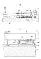
図1は、本発明の第1の実施の形態に係るセンサ用シャッタ体を含む鍵盤装置の構造を示す側断面図(同図(a))及び同装置の要部の部分拡大図(同図(b))である。
【0031】
本装置は、多数の並設された鍵2(白鍵2a及び黒鍵2b)からなる鍵盤4を備えている。以下、鍵2の奏者側を本装置の「前側」乃至「前方」と呼称する。棚板6の上面には、本装置の全幅に亘って延在するフロントレール9、バランスレール3及びバックレール5が前方から順に取り付けられており、これら3本のレールによって鍵盤4が支持される。
【0032】
バランスレール3には、バランスピン3aが各鍵2に対応して立設されている。バランスピン3aにより、各鍵2の前後方向への移動が規制される。また、各鍵2は、バランスピン3a近傍の部分を支点として上下方向に揺動する。フロントレール9には、フロントピン9aが立設され、フロントピン9aは、押鍵操作時に各鍵2の前部の鍵並び方向への移動を規制する。
【0033】
フロントレール9とバランスレール3との間であって、棚板6の上方には、光センサユニット10が設けられる。同図(b)に示すように、光センサユニット10は、各鍵2に対応して光センサ部11を備える。ベースプレート13に立設された支柱部14A、14Bにより、トッププレート12が支持され、各光センサ部11は、トッププレート12の下面にネジ止め固定されている。
【0034】
光センサ部11は、発光部11aと受光部11bとを有して成り、対応する鍵2の下方に配設される。発光部11aと受光部11bとは、両者間の光の経路軸が、押離鍵動作で揺動する鍵2の旋回面を垂直に貫通するように対向配置されている。支柱部14A、14Bはトッププレート12の高さを調整可能に構成されており、これにより、発光部11aと受光部11bとの間の光の経路軸の位置調整ができる。
【0035】
一方、各鍵2の下面2cには、センサ用シャッタ体30が各光センサ部11に対応して設けられる。
【0036】
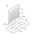
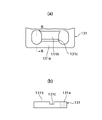
図2は、センサ用シャッタ体30の外観図である。センサ用シャッタ体30(以下、「シャッタ体30」と称する)は、シャッタホルダ31にシャッタ板32が取り付けられて成る。図3は、シャッタホルダ31のシャッタ板32取り付け側からみた平面図(同図(a))、及び同図(a)のA−A線に沿う断面の端面図(同図(b))である。
【0037】
光センサ部11、シャッタホルダ31及びシャッタ板32で、「鍵センサ」が構成される。シャッタ体30は、鍵センサを構成する部品であり、「センサ用部品体」を構成し、シャッタホルダ31は、「センサ用ホルダ」を構成する。
【0038】
シャッタ板32は、例えばPET(Poly Ethylene Terephthalate)等の弾性を有する透明性基材をフィルム状に形成して成り、シャッタホルダ31に保持されている。図2に示すように、シャッタ板32の片面には、黒色塗料にてテーパパターン32aが施されている。シャッタ体30は、押鍵操作されたとき、対応する光センサ部11の経路軸がシャッタ板32のテーパパターン32aを垂直に貫通するように配置される。
【0039】
鍵2が押鍵操作されると、鍵2に連動してシャッタ板32が光センサ部11の経路軸を横断する。このとき、テーパパターン32aの存在により、受光部11bでの受光量が鍵2の位置に応じて変化する。そして、その光量の変化を反映した検出信号が、受光部11bから出力され、これにより、鍵2の運動が検出される。
【0040】
シャッタホルダ31は、略長方形の板部材で、例えばポリアセタール、ナイロン等の合成樹脂で一体に形成される。図3(a)に示すように、シャッタホルダ31は、基端部31aと、シャッタ板32が取り付けられる部分であるシャッタ板取付側端部31cとを有する。シャッタ板取付側端部31cには、突設片31e、穴31f、係止部31dA、31dBが形成される。
【0041】
シャッタ板32は、突設片31e、穴31f、係止部31dA、31dBに係止されることで、シャッタホルダ31に取り付けられる。これら突設片31e、穴31f、及び係止部31dA、31dBで、「センサ部品取付部」が構成される。なお、シャッタ板32のシャッタホルダ31への取り付けは、通常、シャッタホルダ31を鍵2に装着する前に行われるが、装着した後に行うようにしてもよい。
【0042】
基端部31aからは、タイプレート31bがシャッタ板取付側端部31cに向かって片持ち構造で延設されている。タイプレート31bは、後述するステープル針42により鍵2の下面2cに固定される部分である。タイプレート31bの先端とシャッタ板取付側端部31cとの間には間隙CL1が形成されており、従って、タイプレート31bは、基端部31aで片持ち梁のように支持される。
【0043】
また、図3(b)に示すように、基端部31aとタイプレート31bとの間には段差が設けられる。タイプレート31bは基端部31aよりもH1だけ薄く形成されている。また、H1は、ステープル針42の厚みB1(図5参照)とほぼ等しい値に設定されている。
【0044】
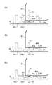
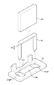
図4は、シャッタホルダ31をステープル針42により鍵2の下面2cに固定する手順を示す模式図である。同図では、鍵2の下面2cが上方を向いている。図5は、シャッタホルダ31の固定にかかわる主な構成要素を示す外観図である。なお、図4、図5では、シャッタ板32の図示が省略されている。
【0045】
ステープラ40は、ステープル針を打ち込む一般的な構成の固定装置である。図4に示すように、ステープラ40は、内装されたコ字状のステープル針42を押圧駆動して繰り出し口40aから繰り出すドライバ(以下、「押し子41」と称する)を有する。ステープラ40の繰り出し口40aは、下端部40bと略面一になっている。
【0046】
まず、ステープラ40を鍵2の下面2cに向かって移動させると、図4(a)に示すように、ステープラ40の下端部40bがシャッタホルダ31の基端部31aの上端31aaに当接して移動が停止する。これにより、ステープラ40の打ち込み駆動開始位置が規定される。この駆動開始位置では、ステープラ40の繰り出し口40aとタイプレート31bとの間には、基端部31aとタイプレート31bとの段差分H1(図3(b)参照)に相当する間隙CL2が生じている。また、このとき、図5に示すように、ステープル針42は、その両針先がシャッタホルダ31の楕円状の穴31gA、31gBの同図上方に位置し、タイプレート31bの同図上方から押さえ込むような姿勢になるようになっている。
【0047】
次に、ステープラ40の押し子41でステープル針42を押圧駆動し、鍵2の下面2cに打ち込んでいく(図4(b))。鍵2は木製であって弾性を有するので、ステープル針42がさらに押し込まれると、図4(c)に示すように、鍵2が塑性変形する。押し子41による押圧力は毎回ほぼ一定であるので、押し子41は一定の量であるD1(約0.3mm)だけオーバーシュートして止まる。また、それに伴って、タイプレート31bは基端部31aを支点として片持ち梁のように撓み、タイプレート31bが鍵2の下面2cに確実に固定されることで、シャッタホルダ31が鍵2に装着される。このとき、タイプレート31bが撓んでいることで、タイプレート31bには応力が生じており、この応力が残存することで固定状態が維持されることになるが、その一方で、タイプレート31bには歪みが生じることになる。しかし、片持ち梁構造であるため、タイプレート31bの歪みはシャッタ板32にほとんど影響しない。
【0048】
本実施の形態によれば、シャッタ板取付側端部31cでシャッタ板32を支持するようにすると共に、シャッタ板取付側端部31cに対して離間した反対側の端部である基端部31aから、タイプレート31bを片持ち構造で延設するようにし、タイプレート31bの先端とシャッタ板取付側端部31cとを接続することなく両者間に間隙CL1を形成したので、例えば、タイプレート31bがシャッタ板取付側端部31cと直接連結されている場合に比し、ステープル針42での固定時に生じるタイプレート31bの歪みがシャッタ板32に伝わりにくい。
【0049】
すなわち、D1分のオーバーシュートでタイプレート31bが撓んだことで、基端部31aには、反力や曲げ応力がかかり、多少の歪みを生じることになるが、タイプレート31bが片持ち構造で間隙CL1が存在することから、その歪みの影響がシャッタ板取付側端部31c側には及びにくく、シャッタ板取付側端部31c近傍では歪みがほとんど生じない。しかも、タイプレート31bの厚みが、シャッタホルダ31における他の部分に比し薄くなっているので、タイプレート31bの歪みがシャッタホルダ31全体に及びにくくなっていることから、一層有利である。
【0050】
また、基端部31aのストッパ機能により規定されるステープラ40の打ち込み駆動開始位置において、繰り出し口42とタイプレート31bとの間に、間隙CL2が確保されるようにしたので、略一定の押圧力の下では、ステープラ40の下端部40bがタイプレート31bに当接した状態からステープル針42の打ち込みを開始する場合に比し、押し子41のオーバーシュートをほぼ一定の適当な量(D1)に抑えることができる。これにより、シャッタホルダ31に生じる歪みが適当に減少する。
【0051】
従って、これらから、シャッタホルダ31の鍵2への取り付け時に生じるタイプレート31bの歪みをシャッタ板32に伝わりにくくすると共に、ステープル針42の打ち込みのオーバーシュートを適当に抑制して過剰な歪みを防止することで、合成樹脂製のシャッタホルダ31のように、剛性がそれほど高くなくても、鍵センサとしての検出精度への悪影響を減少させることができる。鍵盤装置への後付けにも対応が容易である。
【0052】
また、タイプレート31bは、シャッタ板取付側端部31cに向かって延設したので、タイプレート31bがシャッタホルダ31のほぼ中央に位置するようになり、シャッタホルダ31の形成が容易であるだけでなく、コンパクトでありながら鍵2に対して安定して固定される。
【0053】
なお、D1は、例示した値に限定されず、押し子41の押圧力や鍵2の材質等に応じて設定すればよく、ステープル針42の打ち込みのオーバーシュートを最適にして、タイプレート31bに過剰な歪みを与えないような適切な値に設定するのが望ましい。
【0054】
なお、本実施の形態では、被測定物として鍵盤装置の鍵を例示したが、ステープル針でセンサ用シャッタ体が装着されるものであれば、これに限るものでなく、例えば、鍵盤装置のハンマやペダル等の他の要素を被測定物としてもよい。例えば、ハンマに装着するときは、ハンマシャンクの長手方向にシャッタ体が平行になるように取り付ければよい。また、鍵盤装置に限らず、他の装置に適用してもよい。
【0055】
なお、本発明は、連続光量変化の透過型センサに用いるだけでなく、貫通口による透過光と遮光によるオン/オフ型のセンサや反射型センサを採用する場合のシャッタ体の取り付けに応用することもできる。
【0056】
なお、センサ用シャッタ体30は、シャッタホルダ31とは別体で構成したが、シャッタホルダ31を高透過性の材料で形成することで、両者を一体構成としてもよい。また、センサがオン/オフ型であれば、遮光できる材料でセンサ用シャッタ体30とシャッタホルダ31とを一体に形成すればよい。
【0057】
なお、光センサ部11、シャッタホルダ31及びシャッタ板32で、「鍵センサ」が構成されるとしたが、シャッタ板32と光センサ部11との配置を逆にして、シャッタホルダ31に光センサ部11を取り付け、これらとシャッタ板32とで鍵センサを構成してもよく、この場合にも本発明を適用可能である。また、シャッタホルダ31に相当するセンサ用ホルダに取り付けられるセンサ部品としては、上記光センサ部11やシャッタ板32に限定されず、センサ用ホルダの歪みが検出精度に影響しやすい検出機構における何らかのセンサ部品であればよい。また、センサ用ホルダに取り付けられるセンサ部品は複数でもよく、逆に、複数のセンサ部品が1つのセンサ用ホルダに取り付けられる場合であってもよい。
【0058】
本実施の形態では、タイプレート31bの厚みを、シャッタホルダ31における他の部分の厚みよりも薄くすることで、タイプレート31bの歪みがシャッタホルダ31全体に及ぶことを一層効果的に抑制しているが、そのような観点からは、次のような変形例も採用可能である。
【0059】
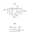
図6(a)は、本実施の形態における第1の変形例に係るシャッタホルダのシャッタ板取り付け側からみた部分平面図である。図6(b)は、同図(a)のB−B線に沿う断面の端面図である。
【0060】
同図に示すように、シャッタホルダ131の基端部131aからは、タイプレート131bが片持ち構造で延設されている。タイプレート131bの厚みは、基端部131aの厚みとほぼ同じであるが、タイプレート131bの基端部131a寄りには、薄肉部である溝部131cが形成される。この溝部131cを設けたことで、タイプレート131bの歪みがシャッタホルダ131全体に及ぶことが抑制される。
【0061】
図7(a)は、本実施の形態における第2の変形例に係るシャッタホルダのシャッタ板取り付け側からみた部分平面図である。図7(b)は、同図(a)のC−C線に沿う断面の端面図である。
【0062】
同図に示すように、シャッタホルダ231の基端部231aからは、タイプレート231bが片持ち構造で延設されている。タイプレート231bの基端部131a寄りには、同図(a)における左右両側に、切り欠き部231c1、231c2が形成される。これら切り欠き部231c1、231c2を設けたことで、タイプレート231bの歪みがシャッタホルダ231全体に及ぶことが抑制される。
【0063】
(第2の実施の形態)
第1の実施の形態では、ステープラ40を用いてステープル針42を打ち込むことでシャッタホルダを鍵2に固定する場合を示したが、第2の実施の形態では、ステープラ40でなくハンマを用いてステープル針42を打ち込む場合を例示する。本実施の形態では、シャッタホルダの構成が第1の実施の形態と異なる。
【0064】
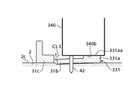
図8は、本発明の第2の実施の形態においてシャッタホルダをステープル針42により鍵2の下面2cに固定する手順を示す模式図である。同図では、鍵2の下面2cが上方を向いている。
【0065】
本実施の形態のシャッタホルダ331は、基端部331aの厚みが第1の実施の形態における基端部31aより薄い点が異なり、その他の構成は第1の実施の形態におけるシャッタホルダ31と同様である。また、本第2の実施の形態では、押し子を用いず、ハンマ340がステープル針42を直接打ち込む点で第1の実施の形態と異なる。その他の構成は第1の実施の形態と同様である。
【0066】
図8に示すように、シャッタホルダ331の基端部331aとタイプレート31bとには段差CL3が設けられている。従って、ハンマ340がステープル針42を打ち込むとき、ハンマ340の下端部340bが基端部331aの上端331aaに当接することで、その押圧駆動方向における駆動終了位置が規定され、そのとき、下端部340bとタイプレート31bとの間に、段差CL3に相当する間隙が生じることになる。
【0067】
ここで、上記段差CL3は、第1の実施の形態における間隙CL2からD1(約0.3mm)を引いた値(CL3=CL2−D1)に設定されている。従って、駆動終了時には、ステープル針42は、第1の実施の形態の場合と同程度の深さで鍵2に打ち込まれることになるので、第1の実施の形態で押し子41のオーバーシュートを適当に抑制したのと同様に、タイプレート331bに過剰な歪みを与えないようにすることができる。
【0068】
本実施の形態によれば、ステープル針42の打ち込み深さを一定にすることで、タイプレート331bの過剰な歪みを防止でき、低い剛性であっても検出精度への悪影響を減少させることに関し、第1の実施の形態と同様の効果を奏することができる。
【0069】
なお、上記各実施の形態において、駆動体としてステープラ40及びハンマ340、取付材としてステープル針42を例示したが、これらに限るものでなく、押圧を伴う駆動により取付材を取り付ける態様であれば、広く応用が可能である。例えば、取付材は釘、鋲体、ネジ等であってもよく、取付材がネジである場合は、駆動体はネジ回し工具となる。
【0070】
なお、上記各実施の形態では、ステープル針等の取付材を用いてシャッタホルダを鍵に取り付ける場合を例示したが、タイプレートの歪みは、応力が生じることに起因するので、タイプレートが、応力が残存する態様で固定されることで鍵等の可塑性部材に対して固定状態が維持されるような固定手法であれば、本発明を適用可能である。例えば、シャッタホルダを取り付ける場合だけでなく、光センサ部11等のセンサ部品を可塑性部材に取り付ける場合や、あるいはセンサ部品を組み付けたセンサ用ホルダを可塑性部材に取り付ける場合にも、本発明を適用可能である。
【0071】
また、上述のように、取付材の種類を問わないだけでなく、別部材として構成される取付材を用いない固定手法であっても本発明の適用の可能性はある。例えば、タイプレートの可塑性部材に対向する面に突起部を設けると共に、それに対応する嵌合穴を可塑性部材に設け、両者を嵌合することで固定状態になる場合や、上記嵌合穴に接着剤を満たしておき、タイプレートを少し押し込んで上記突起部を嵌合穴に嵌合した状態で接着剤が凝固することで、タイプレートに応力が残ったまま安定した固定状態となる、というような場合にも、本発明を適用することができる。
【0072】
【発明の効果】
以上説明したように、本発明によれば、低い剛性であっても検出精度への悪影響を減少させることができる。
【図面の簡単な説明】
【図1】 本発明の第1の実施の形態に係るセンサ用シャッタ体を含む鍵盤装置の構造を示す側断面図(同図(a))及び同装置の要部の部分拡大図(同図(b))である。
【図2】 センサ用シャッタ体の外観図である。
【図3】 シャッタホルダのシャッタ板取り付け側からみた平面図(同図(a))、及び同図(a)のA−A線に沿う断面の端面図(同図(b))である。
【図4】 シャッタホルダをステープル針により鍵の下面に固定する手順を示す模式図である。
【図5】 シャッタホルダの固定にかかわる主な構成要素を示す外観図である。
【図6】 同実施の形態における第1の変形例に係るシャッタホルダのシャッタ板取り付け側からみた部分平面図(同図(a))、及び同図(a)のB−B線に沿う断面の端面図(同図(b))である。
【図7】 同実施の形態における第2の変形例に係るシャッタホルダのシャッタ板取り付け側からみた部分平面図(同図(a))、及び同図(a)のC−C線に沿う断面の端面図(同図(b))である。
【図8】 本発明の第2の実施の形態においてシャッタホルダをステープル針により鍵の下面に固定する手順を示す模式図である。
【符号の説明】
2 鍵(被測定物、可塑性部材)、 11 光センサ部(センサ部品)、 30 センサ用シャッタ体(センサ用部品体)、 31、331 シャッタホルダ(ベース部、センサ用ホルダ)、 31a、331a 基端部(反対側の端部、当接部)、 31b タイプレート(被固定部)、 31c シャッタ板取付側端部(一端部)、 31dA、31dB 係止部(センサ部品取付部の一部)、31e 突設片(センサ部品取付部の一部)、 31f 穴(センサ部品取付部の一部)、 32 シャッタ板(センサ部品)、 40 ステープラ、 40a 繰り出し口、 41 押し子(駆動部)、 42 ステープル針(取付材)、 340 ハンマ(駆動体)、 CL2 間隙(所定の間隙)、 CL3 段差(所定の間隙)[0001]
[Field of the Invention]
The present invention relates to a sensor shutter body, a sensor component body, and a sensor holder that are mounted on a plastic member such as a key of a keyboard device with a staple needle or the like.
[0002]
[Prior art]
2. Description of the Related Art Conventionally, there is a keyboard device such as an automatic piano as one of a staple needle or the like to which a sensor shutter body, a sensor component body or a sensor holder is attached, and this device has a key as a measurement object. One provided with a key sensor for detecting an operation is known. The key sensor is generally composed of an optical sensor main body disposed below each key, in which a light receiving element and a light emitting element are arranged to face each other, and a shutter body mounted on the back surface of each key. The shutter body generally includes a base portion (shutter holder) attached to the lower surface of the key and a shutter plate extending vertically from the base portion, and the shutter plate has an optical filter whose transmitted light amount varies depending on the position. . Then, when the shutter body mounted on the pressed key moves along with the key pressing operation, and the shutter plate crosses the path between the corresponding light receiving element and the light emitting element, the amount of light received by the light receiving element is reduced. The key pressing operation is detected by utilizing the change.
[0003]
By the way, as exemplified in
[0004]
In addition, the shutter body is provided with a notched bifurcated joint, and a corresponding hole is provided in the lower surface of the key, and the joint of the shutter body is inserted into the key-side hole so that the shutter body is locked. The keyboard device that is held and fixed to theMan(Japanese Patent Application No. 2001-232455) (hereinafter referred to as “proposed technology”).
[0005]
[Patent Document 1]
Japanese Patent Laid-Open No. 3-1554097
[Patent Document 2]
JP 2001-195071 A
[0006]
[Problems to be solved by the invention]
However, in the prior art disclosed in
[0007]
On the other hand, in the proposed technique, the problem of distortion does not occur because the staple needle is not used. However, the configuration is complicated because a hole must be provided in each key. In particular, the shutter body may be retrofitted to the keyboard device as a product, and it is time-consuming to make a hole in the lower surface of the key later, ensuring the quality of the keyboard device and ensuring the detection accuracy of the key press operation. Is also not preferable.
[0008]
The present invention has been made to solve the above-described problems of the prior art, and its object is to provide a sensor shutter body, a sensor component body, which can reduce the adverse effects on detection accuracy even with low rigidity, The object is to provide a sensor holder.
[0009]
[Means for Solving the Problems]
In order to achieve the above object, a sensor shutter body according to claim 1 of the present invention is a sensor shutter body mounted on a measurement object with a staple needle, and is provided on a base portion and the base portion. A fixed portion fixed to the object to be measured by a staple, and a shutter plate extending from one end portion of the base portion, the fixed portion being separated from the one end portion of the base portion; SiteFrom the end opposite to the one end to the one endIt is characterized by being extended in a cantilever structure.
[0010]
According to this configuration, CoveredThe distortion of the fixed portion that occurs during attachment to the measurement object can be made difficult to be transmitted to the shutter plate, and adverse effects on detection accuracy can be reduced even with low rigidity.In addition to being easy to form, it is compact and can be stably fixed to the object to be measured.
[0012]
To achieve the above object, the claims of the present invention are described.2The sensor shutter body is a sensor shutter body that is mounted on the object to be measured with the staple needle by a stapler that has a drive unit that presses and drives the staple needle and feeds it out from the feed-out port. A fixed portion that is fixed to the object to be measured by the staple, a shutter plate that extends from the base portion, and a base plate that is in contact with the stapler and contacts the stapler. And a contact portion that defines a driving driving start position, and at the driving driving start position, a predetermined gap is secured between the feeding port of the stapler and the fixed portion. It is characterized by that.
[0013]
According to this configuration, a predetermined gap is secured between the stapler feed-out port and the fixed portion of the shutter body at the driving start position of the stapler where the stapler contacts the contact portion of the base portion. Not only can the overshoot of the part be reduced, but the overshoot can also be made substantially constant under a substantially constant pressing force of the drive part. Therefore, excessive distortion can be prevented by appropriately suppressing overshooting of staple needle driving, and adverse effects on detection accuracy can be reduced even with low rigidity.
[0014]
In addition, the above claims2In the configuration described above, it is desirable that the predetermined gap is set to be approximately equal to the thickness of the staple needle in the feeding direction of the staple needle. According to this configuration, it is possible to more appropriately prevent excessive distortion by optimizing the overshoot of the staple needle driving.
[0015]
To achieve the above object, the claims of the present invention are described.4The sensor shutter body is a sensor shutter body that is mounted on the object to be measured with the staple needle by a stapler that has a drive unit that presses and drives the staple needle and feeds it out from the feed-out port. A fixed portion that is fixed to the object to be measured by the staple needle, a shutter plate that extends from one end of the base portion, and a base plate that is in contact with the stapler. The fixed portion is spaced from the one end portion of the base portion.From the end opposite to the one end to the one endA cantilever structure is extended from the front, and a predetermined gap is secured between the feeding port of the stapler and the fixed portion at the driving driving start position. .
[0016]
According to this configuration, the distortion of the fixed portion that occurs during attachment to the object to be measured is made difficult to be transmitted to the shutter plate, and excessive distortion is prevented by appropriately suppressing the overshoot of the staple needle driving, Even if the rigidity is low, adverse effects on detection accuracy can be reduced.
[0017]
To achieve the above object, the claims of the present invention are described.5The sensor component body ofOKA sensor component body mounted on a plastic member, comprising a base part, a sensor part provided at one end of the base part, and a base part.,in frontFixed against plastic membersDefiniteThe fixed portion is a portion spaced apart from the one end portion of the base portion.From the end opposite to the one end to the one endIt is characterized by being extended in a cantilever structure.
[0018]
According to this configuration, due to the same action as that of the first aspect, it is difficult to transmit the distortion of the fixed portion that occurs at the time of attachment to the plastic member to the sensor component, and the adverse effect on the detection accuracy is reduced even with low rigidity. be able to.
[0019]
In order to achieve the above object, a sensor component body according to claim 7 of the present invention is a sensor component body mounted on the plastic member by attaching an attachment material to the plastic member by driving accompanied by pressing by the driving body. A base part, a sensor component provided in the base part, and a base part.In the mounting materialSolid to the plastic memberDefiniteAnd a contact portion that is provided on the base portion and abuts against the drive body to define a drive end position in the pressing direction of the drive body, and at the drive end position, the drive body And a predetermined gap between the fixed portion and the fixed portion.
[0020]
According to this configuration, since the predetermined gap is secured between the drive body and the fixed portion at the drive end position where the drive body abuts on the contact portion of the base portion, the mounting material is excessive from the drive body. It is prevented from receiving a pressing force. Therefore, excessive distortion of the fixed portion can be prevented by appropriately suppressing the overshoot of the mounting material, and adverse effects on detection accuracy can be reduced even with low rigidity.
[0021]
In order to achieve the above object, a sensor component body according to claim 8 of the present invention is a sensor component body mounted on the plastic member by attaching an attachment material to the plastic member by driving accompanied by pressing by the driving body. A base part, a sensor component provided at one end of the base part, and a base part.In the mounting materialSolid to the plastic memberDefiniteA fixed portion that is provided on the base portion, and a contact portion that contacts the driving body and defines a driving end position in a pressing direction of the driving body, and the fixed portion includes the base portion The part spaced apart from the one end inFrom the end opposite to the one end to the one endA cantilever structure is provided, and a predetermined gap is secured between the driving body and the fixed portion at the driving end position.
[0022]
According to this configuration, it is difficult to transmit the distortion of the fixed part that occurs during the attachment to the plastic member to the sensor component, and the excessive distortion of the fixed part is prevented by appropriately suppressing the overshoot of the mounting material. Even if the rigidity is low, adverse effects on detection accuracy can be reduced.
[0023]
In order to achieve the above object, the sensor holder according to
[0024]
According to this configuration, due to the same action as that of the first aspect, it is difficult to transmit the distortion of the fixed portion that occurs at the time of attachment to the plastic member to the sensor component, and the adverse effect on the detection accuracy is reduced even with low rigidity. be able to.
[0025]
To achieve the above object, the claims of the present invention are described.11The sensor holder is a sensor holder that is attached to the plastic member by attaching an attachment material to the plastic member by driving accompanied by pressing by a driving body. The sensor holder is provided in the base portion and the base portion. A sensor component mounting portion for mounting the base, and the base portion,With the mounting materialSolid to the plastic memberDefiniteAnd a contact portion that is provided on the base portion and abuts against the drive body to define a drive end position in the pressing direction of the drive body, and at the drive end position, the drive body And a predetermined gap between the fixed portion and the fixed portion.
[0026]
With this configuration, the same function and effect as that of the seventh aspect can be achieved.
[0027]
To achieve the above object, the claims of the present invention are described.12The sensor holder is a sensor holder that is attached to the plastic member by attaching an attachment material to the plastic member by driving accompanied by pressing by a driving body, and is provided at a base portion and one end portion of the base portion. A sensor component mounting portion for mounting the sensor component and the base portionIn the mounting materialSolid to the plastic memberDefiniteA fixed portion that is provided on the base portion, and a contact portion that contacts the driving body and defines a driving end position in a pressing direction of the driving body, and the fixed portion includes the base portion The part spaced apart from the one end inFrom the end opposite to the one end to the one endA cantilever structure is provided, and a predetermined gap is secured between the driving body and the fixed portion at the driving end position.
[0028]
According to this structure, the same effect as that of the eighth aspect can be achieved.
[0029]
DETAILED DESCRIPTION OF THE INVENTION
Hereinafter, embodiments of the present invention will be described with reference to the drawings.
[0030]
(First embodiment)
FIG. 1 is a side sectional view showing the structure of a keyboard device including a sensor shutter body according to a first embodiment of the present invention (FIG. 1A), and a partially enlarged view of the main part of the device (FIG. (B)).
[0031]
This apparatus includes a keyboard 4 made up of a number of keys 2 (white key 2a and black key 2b) arranged in parallel. Hereinafter, the player side of the
[0032]
On the
[0033]
An
[0034]
The
[0035]
On the other hand, on the
[0036]
FIG. 2 is an external view of the
[0037]
The
[0038]
The
[0039]
When the
[0040]
The
[0041]
The
[0042]
A
[0043]
Moreover, as shown in FIG.3 (b), a level | step difference is provided between the
[0044]
FIG. 4 is a schematic diagram showing a procedure for fixing the
[0045]
The
[0046]
First, when the
[0047]
Next, the
[0048]
According to the present embodiment, the
[0049]
That is, since the
[0050]
In addition, since the gap CL2 is secured between the feeding
[0051]
Accordingly, the distortion of the
[0052]
In addition, since the
[0053]
Note that D1 is not limited to the exemplified value, and may be set in accordance with the pressing force of the
[0054]
In the present embodiment, the key of the keyboard device is exemplified as the object to be measured. However, the present invention is not limited to this as long as the sensor shutter body is mounted with a staple needle. For example, the hammer of the keyboard device is used. Other elements such as a pedal and a pedal may be measured. For example, when mounting on a hammer, the shutter body may be mounted in parallel with the longitudinal direction of the hammer shank. Moreover, you may apply not only to a keyboard apparatus but to another apparatus.
[0055]
The present invention is applied not only to a transmissive sensor with a continuous light quantity change, but also to an attachment of a shutter body when an on / off type sensor or a reflective sensor using a transmitted light and a light shield by a through-hole is adopted. You can also.
[0056]
In addition, although the
[0057]
Note that the
[0058]
In the present embodiment, the thickness of the
[0059]
FIG. 6A is a partial plan view seen from the shutter plate mounting side of the shutter holder according to the first modification of the present embodiment. FIG.6 (b) is an end elevation of the cross section which followed the BB line of the figure (a).
[0060]
As shown in the figure, a
[0061]
FIG. 7A is a partial plan view seen from the shutter plate mounting side of the shutter holder according to the second modification example of the present embodiment. FIG.7 (b) is an end elevation of the cross section along the CC line of the figure (a).
[0062]
As shown in the figure, a
[0063]
(Second Embodiment)
In the first embodiment, the case where the
[0064]
FIG. 8 is a schematic diagram showing a procedure for fixing the shutter holder to the
[0065]
The
[0066]
As shown in FIG. 8, a step CL3 is provided between the
[0067]
Here, the level difference CL3 is set to a value (CL3 = CL2-D1) obtained by subtracting D1 (about 0.3 mm) from the gap CL2 in the first embodiment. Accordingly, at the end of driving, the
[0068]
According to the present embodiment, it is possible to prevent excessive distortion of the tie plate 331b by making the driving depth of the
[0069]
In each of the above-described embodiments, the
[0070]
In each of the above embodiments, the case where the shutter holder is attached to the key using an attachment material such as a staple needle is exemplified. However, since the distortion of the tie plate is caused by the occurrence of stress, the tie plate is stressed. As long as the fixing method is such that the fixed state is maintained with respect to the plastic member such as the key by being fixed in such a manner as to remain, the present invention can be applied. For example, the present invention can be applied not only when a shutter holder is attached, but also when a sensor component such as the
[0071]
In addition, as described above, the present invention is not limited to the type of attachment material, and may be applied to a fixing method that does not use an attachment material configured as a separate member. For example, a protrusion is provided on the surface facing the tie plate plastic member, and a corresponding fitting hole is provided in the plastic member. Fill the agent, push the tie plate a little and the adhesive solidifies in a state where the protrusion is fitted in the fitting hole, so that the tie plate is in a stable fixed state with stress remaining. Even in such a case, the present invention can be applied.
[0072]
【The invention's effect】
As described above, according to the present invention, it is possible to reduce adverse effects on detection accuracy even with low rigidity.
[Brief description of the drawings]
FIG. 1 is a side sectional view showing the structure of a keyboard device including a sensor shutter body according to a first embodiment of the present invention (FIG. 1A), and a partially enlarged view of the main part of the device (FIG. 1). (B)).
FIG. 2 is an external view of a sensor shutter body.
3A is a plan view of the shutter holder as viewed from the shutter plate mounting side (FIG. 3A), and FIG. 3A is an end view of the cross section taken along line AA of FIG.
FIG. 4 is a schematic diagram showing a procedure for fixing the shutter holder to the lower surface of the key with a staple needle.
FIG. 5 is an external view showing the main components involved in fixing the shutter holder.
6 is a partial plan view of the shutter holder according to the first modification of the embodiment viewed from the shutter plate mounting side (FIG. 6A), and a cross section taken along line BB in FIG. 6A; It is an end view (the figure (b)).
7 is a partial plan view of the shutter holder according to the second modification of the embodiment viewed from the shutter plate mounting side (FIG. 7A), and a cross section taken along the line CC in FIG. 7A; It is an end view (the figure (b)).
FIG. 8 is a schematic diagram showing a procedure for fixing the shutter holder to the lower surface of the key with staples in the second embodiment of the present invention.
[Explanation of symbols]
2 Key (measurement object, plastic member), 11 optical sensor part (sensor part), 30 sensor shutter body (sensor part body), 31, 331 shutter holder (base part, sensor holder), 31a, 331a base End portion (opposite end portion, contact portion), 31b tie plate (fixed portion), 31c Shutter plate mounting side end portion (one end portion), 31dA, 31dB locking portion (part of sensor component mounting portion) 31e Projection piece (part of sensor part mounting part), 31f hole (part of sensor part mounting part), 32 Shutter plate (sensor part), 40 Stapler, 40a Feeding port, 41 Pusher (drive part), 42 Staple needle (mounting material), 340 Hammer (driving body), CL2 gap (predetermined gap), CL3 step (predetermined gap)
Claims (12)
ベース部(31)と、
前記ベース部に設けられ、前記ステープル針(42)にて前記被測定物(2)に固定される被固定部(31b)と、
前記ベース部の一端部(31c)から延設されたシャッタ板(32)とを有し、
前記被固定部は、前記ベース部における前記一端部から離間した部位である、前記一端部の反対側の端部(31a)から、前記一端部に向かって片持ち構造で延設されたことを特徴とするセンサ用シャッタ体。A sensor shutter body mounted on an object to be measured with a staple needle,
A base (31);
A fixed portion (31b) provided on the base portion and fixed to the object to be measured (2) by the staple needle (42);
A shutter plate (32) extending from one end (31c) of the base portion,
The fixed portion extends from the end portion (31a) on the side opposite to the one end portion in a cantilever structure from the one end portion of the base portion. A sensor shutter body.
ベース部と、
前記ベース部に設けられ、前記ステープル針(42)にて前記被測定物に固定される被固定部と、
前記ベース部から延設されたシャッタ板と、
前記ベース部に設けられ、前記ステープラ(40)と当接して該ステープラの打ち込み駆動開始位置を規定する当接部(31a)とを有し、
前記打ち込み駆動開始位置において、前記ステープラの前記繰り出し口(40a)と前記被固定部との間に所定の間隙(CL2)が確保されるように構成されたことを特徴とするセンサ用シャッタ体。A sensor shutter body mounted on the object to be measured with the staple needle by a stapler having a drive unit that pushes and drives the staple needle from the feed opening,
A base part;
A fixed portion provided on the base portion and fixed to the object to be measured by the staple needle (42);
A shutter plate extending from the base portion;
A contact portion (31a) provided on the base portion and contacting the stapler (40) to define a driving start position of the stapler;
A sensor shutter body, wherein a predetermined gap (CL2) is secured between the feeding opening (40a) of the stapler and the fixed portion at the driving driving start position.
ベース部と、
前記ベース部に設けられ、前記ステープル針にて前記被測定物に固定される被固定部と、
前記ベース部の一端部から延設されたシャッタ板と、
前記ベース部に設けられ、前記ステープラと当接して該ステープラの打ち込み駆動開始位置を規定する当接部とを有し、
前記被固定部は、前記ベース部における前記一端部から離間した部位である、前記一端部の反対側の端部から、前記一端部に向かってから片持ち構造で延設され、
且つ、前記打ち込み駆動開始位置において、前記ステープラの前記繰り出し口と前記被固定部との間に所定の間隙(CL2)が確保されるように構成されたことを特徴とするセンサ用シャッタ体。A sensor shutter body mounted on the object to be measured with the staple needle by a stapler having a drive unit that pushes and drives the staple needle from the feed opening,
A base part;
A fixed portion provided on the base portion and fixed to the measurement object by the staple needle;
A shutter plate extending from one end of the base portion;
A contact portion that is provided on the base portion and contacts the stapler to define a driving start position of the stapler;
The fixed portion is a portion spaced from the one end portion of the base portion , and is extended in a cantilever structure from the end portion on the opposite side of the one end portion toward the one end portion ,
In addition, the sensor shutter body is configured such that a predetermined gap (CL2) is secured between the feeding opening of the stapler and the fixed portion at the driving driving start position.
ベース部(31)と、
前記ベース部の一端部(31c)に設けられたセンサ部品(32)と、
前記ベース部に設けられ、前記可塑性部材(2)に対して固定される被固定部(31b)とを有し、
前記被固定部は、前記ベース部における前記一端部から離間した部位である、前記一端部の反対側の端部(31a)から、前記一端部に向かって片持ち構造で延設されたことを特徴とするセンサ用部品体。A sensor component body is mounted on the portable plastic member,
A base (31);
A sensor component (32) provided at one end (31c) of the base portion;
Wherein provided on the base portion, and a fixed portion (31b) which is fixed relative to the front Symbol plastic member (2),
The fixed portion extends from the end portion (31a) on the side opposite to the one end portion in a cantilever structure from the one end portion of the base portion. A sensor component.
ベース部(331)と、
前記ベース部に設けられたセンサ部品(32)と、
前記ベース部に設けられ、前記取付材にて前記可塑性部材(2)に対して固定される被固定部(31b)と、
前記ベース部に設けられ、前記駆動体(340)と当接して該駆動体の押圧方向における駆動終了位置を規定する当接部(331a)とを有し、
前記駆動終了位置において、前記駆動体と前記被固定部との間に所定の間隙(CL3)が確保されるように構成されたことを特徴とするセンサ用部品体。A sensor component mounted on the plastic member by attaching the mounting member to the plastic member by driving with pressing by the driving body,
A base (331);
A sensor component (32) provided in the base portion;
Wherein provided on the base portion, the fixed portion which is fixed relative to the plastic member (2) at the mounting member and (31b),
A contact portion (331a) that is provided on the base portion and contacts the drive body (340) to define a drive end position in a pressing direction of the drive body;
A sensor component body configured to ensure a predetermined gap (CL3) between the driving body and the fixed portion at the driving end position.
ベース部(331)と、
前記ベース部の一端部(31c)に設けられたセンサ部品(32)と、
前記ベース部に設けられ、前記取付材にて前記可塑性部材(2)に対して固定される被固定部(31b)と、
前記ベース部に設けられ、前記駆動体(340)と当接して該駆動体の押圧方向における駆動終了位置を規定する当接部(331a)とを有し、
前記被固定部は、前記ベース部における前記一端部から離間した部位である、前記一端部の反対側の端部(331a)から、前記一端部に向かって片持ち構造で延設され、
且つ、前記駆動終了位置において、前記駆動体と前記被固定部との間に所定の間隙(CL3)が確保されるように構成されたことを特徴とするセンサ用部品体。A sensor component mounted on the plastic member by attaching the mounting member to the plastic member by driving with pressing by the driving body,
A base (331);
A sensor component (32) provided at one end (31c) of the base portion;
Wherein provided on the base portion, the fixed portion which is fixed relative to the plastic member (2) at the mounting member and (31b),
A contact portion (331a) that is provided on the base portion and contacts the drive body (340) to define a drive end position in a pressing direction of the drive body;
The fixed portion is a portion spaced from the one end portion of the base portion , and is extended in a cantilever structure from the end portion (331a) opposite to the one end portion toward the one end portion ,
The sensor component body is configured such that a predetermined gap (CL3) is secured between the driving body and the fixed portion at the driving end position.
ベース部と、
前記ベース部の一端部(31c)に設けられ、センサ部品(32)を取り付けるためのセンサ部品取付部(31e、31f、31dA、31dB)と、
前記ベース部に設けられ、前記可塑性部材(2)に対して固定される被固定部(31b)とを有し、
前記被固定部は、前記ベース部における前記一端部から離間した部位である、前記一端部の反対側の端部(31a)から、前記一端部に向かって片持ち構造で延設されたことを特徴とするセンサ用ホルダ。A sensor holder to be mounted on portable plastic member,
A base part;
A sensor component mounting portion (31e, 31f, 31dA, 31dB) for mounting the sensor component (32) provided at one end (31c) of the base portion;
Wherein provided on the base portion, and a fixed portion (31b) which is fixed relative to the front Symbol plastic member (2),
The fixed portion extends from the end portion (31a) on the side opposite to the one end portion in a cantilever structure from the one end portion of the base portion. A sensor holder.
ベース部と、
前記ベース部に設けられ、センサ部品(32)を取り付けるためのセンサ部品取付部(31e、31f、31dA、31dB)と、
前記ベース部に設けられ、前記取付材にて前記可塑性部材(2)に対して固定される被固定部(31b)と、
前記ベース部に設けられ、前記駆動体(340)と当接して該駆動体の押圧方向における駆動終了位置を規定する当接部(331a)とを有し、
前記駆動終了位置において、前記駆動体と前記被固定部との間に所定の間隙(CL3)が確保されるように構成されたことを特徴とするセンサ用ホルダ。A sensor holder to be attached to the plastic member by attaching an attachment material to the plastic member by driving with pressing by a driving body,
A base part;
A sensor component mounting portion (31e, 31f, 31dA, 31dB) for mounting the sensor component (32) provided on the base portion;
Wherein provided on the base portion, the fixed portion which is fixed relative to the plastic member (2) at the mounting member and (31b),
A contact portion (331a) that is provided on the base portion and contacts the drive body (340) to define a drive end position in a pressing direction of the drive body;
A sensor holder, wherein a predetermined gap (CL3) is secured between the driving body and the fixed portion at the driving end position.
ベース部と、
前記ベース部の一端部(31c)に設けられ、センサ部品(32)を取り付けるためのセンサ部品取付部(31e、31f、31dA、31dB)と、
前記ベース部に設けられ、前記取付材にて前記可塑性部材(2)に対して固定される被固定部(31b)と、
前記ベース部に設けられ、前記駆動体(340)と当接して該駆動体の押圧方向における駆動終了位置を規定する当接部(331a)とを有し、
前記被固定部は、前記ベース部における前記一端部から離間した部位である、前記一端部の反対側の端部(331a)から、前記一端部に向かって片持ち構造で延設され、
且つ、前記駆動終了位置において、前記駆動体と前記被固定部との間に所定の間隙(CL3)が確保されるように構成されたことを特徴とするセンサ用ホルダ。A sensor holder to be attached to the plastic member by attaching an attachment material to the plastic member by driving with pressing by a driving body,
A base part;
A sensor component mounting portion (31e, 31f, 31dA, 31dB) for mounting the sensor component (32) provided at one end (31c) of the base portion;
Wherein provided on the base portion, the fixed portion which is fixed relative to the plastic member (2) at the mounting member and (31b),
A contact portion (331a) that is provided on the base portion and contacts the drive body (340) to define a drive end position in a pressing direction of the drive body;
The fixed portion is a portion spaced from the one end portion of the base portion , and is extended in a cantilever structure from the end portion (331a) opposite to the one end portion toward the one end portion ,
A sensor holder, wherein a predetermined gap (CL3) is secured between the driving body and the fixed portion at the driving end position.
Priority Applications (1)
| Application Number | Priority Date | Filing Date | Title |
|---|---|---|---|
| JP2003148045A JP4052182B2 (en) | 2002-05-30 | 2003-05-26 | Sensor shutter body, sensor component body, sensor holder |
Applications Claiming Priority (2)
| Application Number | Priority Date | Filing Date | Title |
|---|---|---|---|
| JP2002157230 | 2002-05-30 | ||
| JP2003148045A JP4052182B2 (en) | 2002-05-30 | 2003-05-26 | Sensor shutter body, sensor component body, sensor holder |
Publications (2)
| Publication Number | Publication Date |
|---|---|
| JP2004054247A JP2004054247A (en) | 2004-02-19 |
| JP4052182B2 true JP4052182B2 (en) | 2008-02-27 |
Family
ID=31949072
Family Applications (1)
| Application Number | Title | Priority Date | Filing Date |
|---|---|---|---|
| JP2003148045A Expired - Fee Related JP4052182B2 (en) | 2002-05-30 | 2003-05-26 | Sensor shutter body, sensor component body, sensor holder |
Country Status (1)
| Country | Link |
|---|---|
| JP (1) | JP4052182B2 (en) |
Families Citing this family (2)
| Publication number | Priority date | Publication date | Assignee | Title |
|---|---|---|---|---|
| JP4650361B2 (en) * | 2006-07-14 | 2011-03-16 | ヤマハ株式会社 | Optical shutter body |
| JP5064784B2 (en) * | 2006-12-20 | 2012-10-31 | 株式会社河合楽器製作所 | Shutter and keyboard device |
-
2003
- 2003-05-26 JP JP2003148045A patent/JP4052182B2/en not_active Expired - Fee Related
Also Published As
| Publication number | Publication date |
|---|---|
| JP2004054247A (en) | 2004-02-19 |
Similar Documents
| Publication | Publication Date | Title |
|---|---|---|
| EP1865492B1 (en) | Keyboard apparatus | |
| JP3129380B2 (en) | Electronic musical instrument keyboard device | |
| JP2003044051A (en) | Key sensor, plate to be detected for the key sensor and keyboard musical instrument | |
| US7514613B2 (en) | Keyboard device for keyboard instrument | |
| JP4052182B2 (en) | Sensor shutter body, sensor component body, sensor holder | |
| US8654406B2 (en) | Image reading apparatus with a transparent member biased by a positioning member | |
| US8681195B2 (en) | Paper detecting device and printer including the same | |
| JP4374803B2 (en) | Optical sensor | |
| US20020062728A1 (en) | Easily assembled optical fiber sensor and musical instrument using the same | |
| US6369309B1 (en) | Keyboard assembly | |
| US7858862B2 (en) | Pedal device for keyboard instrument | |
| JP5532670B2 (en) | Electronic keyboard instrument | |
| US5111041A (en) | Means for securing a photodetector to a base plate or the like | |
| JP4390477B2 (en) | Laser scanning device | |
| US5194994A (en) | Mirror installation in an optical device | |
| WO2023190197A1 (en) | Keyboard pushdown amount sensor device | |
| CN114571870B (en) | Printing unit and portable terminal | |
| WO2017164310A1 (en) | Mounting structure | |
| US20200329172A1 (en) | Image reading apparatus | |
| CN101515449B (en) | Key structure and keyboard apparatus | |
| JP4403022B2 (en) | Substrate support structure, card slot holder having substrate support structure, and thin device | |
| JPH08115079A (en) | Keyboard support device | |
| US20240071345A1 (en) | Keyboard device and key depression information detecting method | |
| JPH0436863B2 (en) | ||
| JP2722977B2 (en) | Keyboard device |
Legal Events
| Date | Code | Title | Description |
|---|---|---|---|
| A621 | Written request for application examination |
Free format text: JAPANESE INTERMEDIATE CODE: A621 Effective date: 20051125 |
|
| RD03 | Notification of appointment of power of attorney |
Free format text: JAPANESE INTERMEDIATE CODE: A7423 Effective date: 20060425 |
|
| A977 | Report on retrieval |
Free format text: JAPANESE INTERMEDIATE CODE: A971007 Effective date: 20070621 |
|
| A131 | Notification of reasons for refusal |
Free format text: JAPANESE INTERMEDIATE CODE: A131 Effective date: 20070626 |
|
| A521 | Written amendment |
Free format text: JAPANESE INTERMEDIATE CODE: A523 Effective date: 20070809 |
|
| TRDD | Decision of grant or rejection written | ||
| A01 | Written decision to grant a patent or to grant a registration (utility model) |
Free format text: JAPANESE INTERMEDIATE CODE: A01 Effective date: 20071113 |
|
| A61 | First payment of annual fees (during grant procedure) |
Free format text: JAPANESE INTERMEDIATE CODE: A61 Effective date: 20071126 |
|
| FPAY | Renewal fee payment (event date is renewal date of database) |
Free format text: PAYMENT UNTIL: 20101214 Year of fee payment: 3 |
|
| R150 | Certificate of patent or registration of utility model |
Ref document number: 4052182 Country of ref document: JP Free format text: JAPANESE INTERMEDIATE CODE: R150 Free format text: JAPANESE INTERMEDIATE CODE: R150 |
|
| FPAY | Renewal fee payment (event date is renewal date of database) |
Free format text: PAYMENT UNTIL: 20101214 Year of fee payment: 3 |
|
| FPAY | Renewal fee payment (event date is renewal date of database) |
Free format text: PAYMENT UNTIL: 20111214 Year of fee payment: 4 |
|
| FPAY | Renewal fee payment (event date is renewal date of database) |
Free format text: PAYMENT UNTIL: 20111214 Year of fee payment: 4 |
|
| FPAY | Renewal fee payment (event date is renewal date of database) |
Free format text: PAYMENT UNTIL: 20121214 Year of fee payment: 5 |
|
| FPAY | Renewal fee payment (event date is renewal date of database) |
Free format text: PAYMENT UNTIL: 20131214 Year of fee payment: 6 |
|
| LAPS | Cancellation because of no payment of annual fees |