WO2023190028A1 - アンギュラ玉軸受 - Google Patents
アンギュラ玉軸受 Download PDFInfo
- Publication number
- WO2023190028A1 WO2023190028A1 PCT/JP2023/011488 JP2023011488W WO2023190028A1 WO 2023190028 A1 WO2023190028 A1 WO 2023190028A1 JP 2023011488 W JP2023011488 W JP 2023011488W WO 2023190028 A1 WO2023190028 A1 WO 2023190028A1
- Authority
- WO
- WIPO (PCT)
- Prior art keywords
- inner member
- ball
- outer member
- diameter
- balls
- Prior art date
- Legal status (The legal status is an assumption and is not a legal conclusion. Google has not performed a legal analysis and makes no representation as to the accuracy of the status listed.)
- Ceased
Links
Images





Classifications
-
- F—MECHANICAL ENGINEERING; LIGHTING; HEATING; WEAPONS; BLASTING
- F16—ENGINEERING ELEMENTS AND UNITS; GENERAL MEASURES FOR PRODUCING AND MAINTAINING EFFECTIVE FUNCTIONING OF MACHINES OR INSTALLATIONS; THERMAL INSULATION IN GENERAL
- F16C—SHAFTS; FLEXIBLE SHAFTS; ELEMENTS OR CRANKSHAFT MECHANISMS; ROTARY BODIES OTHER THAN GEARING ELEMENTS; BEARINGS
- F16C19/00—Bearings with rolling contact, for exclusively rotary movement
- F16C19/02—Bearings with rolling contact, for exclusively rotary movement with bearing balls essentially of the same size in one or more circular rows
- F16C19/14—Bearings with rolling contact, for exclusively rotary movement with bearing balls essentially of the same size in one or more circular rows for both radial and axial load
- F16C19/16—Bearings with rolling contact, for exclusively rotary movement with bearing balls essentially of the same size in one or more circular rows for both radial and axial load with a single row of balls
-
- F—MECHANICAL ENGINEERING; LIGHTING; HEATING; WEAPONS; BLASTING
- F16—ENGINEERING ELEMENTS AND UNITS; GENERAL MEASURES FOR PRODUCING AND MAINTAINING EFFECTIVE FUNCTIONING OF MACHINES OR INSTALLATIONS; THERMAL INSULATION IN GENERAL
- F16C—SHAFTS; FLEXIBLE SHAFTS; ELEMENTS OR CRANKSHAFT MECHANISMS; ROTARY BODIES OTHER THAN GEARING ELEMENTS; BEARINGS
- F16C33/00—Parts of bearings; Special methods for making bearings or parts thereof
- F16C33/30—Parts of ball or roller bearings
- F16C33/38—Ball cages
-
- F—MECHANICAL ENGINEERING; LIGHTING; HEATING; WEAPONS; BLASTING
- F16—ENGINEERING ELEMENTS AND UNITS; GENERAL MEASURES FOR PRODUCING AND MAINTAINING EFFECTIVE FUNCTIONING OF MACHINES OR INSTALLATIONS; THERMAL INSULATION IN GENERAL
- F16C—SHAFTS; FLEXIBLE SHAFTS; ELEMENTS OR CRANKSHAFT MECHANISMS; ROTARY BODIES OTHER THAN GEARING ELEMENTS; BEARINGS
- F16C33/00—Parts of bearings; Special methods for making bearings or parts thereof
- F16C33/30—Parts of ball or roller bearings
- F16C33/58—Raceways; Race rings
Definitions
- the present invention relates to an angular contact ball bearing in which the outer member is separated.
- angular contact ball bearings have an inner member, an outer member, balls (rolling elements), and a cage that are not separated, but depending on the usage conditions, angular contact ball bearings may be of the outer member separated type in which the outer member is separated. Ball bearings may be used. In this case, for example, the outer member is separated and assembled into the housing, the inner member, balls, and retainer are assembled into the shaft, and then the shaft and the housing are assembled. At this time, the outer member of the bearing is easy to separate, and after the outer member is separated, the inner member, balls, and retainer are assembled as assembly parts, making the assembly work easier.
- the counterbore diameter of the inner member is made larger than the inscribed circle diameter of the balls held in a cage that is separated from the inner member. After assembly, the retainer and balls are difficult to separate from the inner member. Therefore, when assembling a bearing, a cage holding balls separated from the inner member is elastically deformed so that the balls can overcome the counter portion of the inner member, and then assembled to the inner member.
- Patent Document 1 some angular contact ball bearings with a separate outer member have a dimensional difference between the outer diameter of the counterbore portion of the inner member and the diameter of the inscribed circle of the ball by 5 to 20% of the ball diameter (Patent Document 1).
- the angular ball bearing of Patent Document 1 does not come off from the inner member even if it is bent by the force of the ball's own weight.
- Patent Document 1 the angular contact ball bearing of Patent Document 1 is based on the premise of using a synthetic resin cage that is easily elastically deformed.In a steel plate cage or a synthetic resin cage that is highly rigid and difficult to elastically deform, the counterbore difficult to overcome. Furthermore, when the width of the inner member increases, it is necessary to greatly deform the retainer, making assembly difficult.
- An object of the present invention is to provide an angular contact ball bearing that makes it easy to assemble a cage to an inner member, and in which the cage does not separate from the inner member after assembly.
- the angular contact ball bearing of the present invention includes an outer member, an inner member, balls that are rolling elements interposed between the outer member and the inner member, and a cage that holds the balls.
- An angular contact ball bearing comprising: an angular contact ball bearing in which the outer member is separable from an assembly component including the inner member, the balls, and the retainer, wherein the counter of the inner member is separated from the bottom of the raceway groove of the inner member.
- the radial distance M to the bore portion is 0.2 to 0.7% of the pitch circle diameter of the ball, and the axial dimension Z of the counterbore portion of the inner member is 8 to 20% of the diameter Dw of the ball.
- the inner member has a first step on its outer peripheral surface adjacent to the counterbore of the inner member and whose diameter is smaller than the counterbore of the inner member, and the first The height X of the step is 0.1 to 0.5% of the pitch circle diameter of the ball.
- the height of the first step in the counterbore of the inner member is 0.1 to 0.5% of the pitch diameter of the ball, and the axial dimension of the counterbore of the inner member is the diameter of the ball.
- the cage can be easily adjusted after assembly. Even if it bends under the force of the ball's own weight, it will not come off from the inner member.
- the axial dimension of the counterbore portion of the inner member is 8 to 20% of the ball diameter, the amount of deformation of the cage can be suppressed and the deformation time can be shortened.
- the first step may be an inclined surface. According to this configuration, by making the first step an inclined surface, the retainer and the balls can smoothly get over the counterbore portion of the inner member, and ease of assembly is improved.
- the outer member has a second step on its inner circumferential surface adjacent to the raceway groove of the outer member and whose diameter is larger than the raceway groove of the outer member, and
- the height Y of the step may be 0.1 to 0.5% of the pitch circle diameter of the ball.
- the outer member may have a straight portion in a portion adjacent to the second step in the raceway groove of the outer member. According to this configuration, the outer member can be smoothly separated from the assembly component, and the outer member can be smoothly incorporated into the assembly component. Therefore, the ease of assembling the bearing is improved.
- FIG. 1 is a sectional view showing an angular contact ball bearing according to a first embodiment of the present invention. It is a sectional view showing an enlarged view of the outer member of the same angular contact ball bearing.
- FIG. 2B is an enlarged view of section B in FIG. 2A. It is a figure which shows the procedure of assembling the retainer and balls of the same angular contact ball bearing to an inner member.
- FIG. 2 is a cross-sectional view showing the shape of a bearing that was evaluated.
- FIG. 7 is a cross-sectional view showing another shape of the bearing that was evaluated.
- FIG. 7 is a cross-sectional view showing still another shape of the bearing that was evaluated.
- FIG. 1 is a sectional view showing an angular contact ball bearing 1 according to a first embodiment of the present invention.
- the angular contact ball bearing 1 of this embodiment includes an outer member 2, an inner member 4, and a plurality of balls 6, which are a type of rolling elements, interposed between the outer member 2 and the inner member 4. , and a retainer 8 for holding balls 6, the outer member 2 is separable from an assembly component As consisting of the inner member 4, the balls 6, and the retainer 8.
- the outer member 2 is fitted into the housing Ho (FIG. 4A), and the inner member 4 is fitted into the shaft Sh (FIG. 4A).
- the retainer 8 of this embodiment is an annular retainer made of synthetic resin, and circular pockets 8a that can freely accommodate the balls 6 from the inner circumferential side are formed at equal intervals in the circumferential direction.
- the material of the cage 8 is, for example, PA9T+GF30% (30% glass-filled polyamide 9T). However, the material of the retainer 8 is not limited to this.
- the inner member 4 has a raceway groove 4a on its outer peripheral surface.
- the balls 6 roll on this raceway groove 4a.
- the inner member 4 further has a counterbore portion 4b on one axial side (left side in FIG. 1) of the raceway groove 4a on the outer peripheral surface.
- the counterbore portion 4b is a portion where the shoulder portion of the raceway groove 4a is cut off, and has a smaller diameter than the opposite counterbore portion 4c (on the right side in FIG. 1).
- the counterbore portion 4b extends in the axial direction from the raceway groove 4a toward one end surface 4d of the inner member 4.
- the inner member 2 has a first step 10 on its outer peripheral surface adjacent to the counterbore portion 4b and having a diameter smaller than the counterbore portion 4b. That is, on the outer peripheral surface of the inner member 2, a counterbore portion 4b that is continuous to the raceway groove 4a via the first step 10 and a small diameter portion 4e that is continuous to the one end surface 4d are formed. The small diameter portion 4e also extends in the axial direction.
- the first step 10 has an inclined surface 10a.
- the inclined surface 10a is inclined so that the diameter thereof decreases from the counterbore portion 4b toward the small diameter portion 4e.
- the first step 10 is not limited to being sloped, and may be a step in which the slope extends in the radial direction.
- the dimensions of the raceway groove 4a, counterbore portion 4b, and first step 10 of the inner member 4 are set as follows. There is.
- the groove bottom 4aa of the raceway groove 4a is the most recessed part of the raceway groove 4a, that is, the part with the smallest diameter.
- the outer member 2 has a raceway groove 2a on its inner peripheral surface.
- the balls 6 roll on this raceway groove 2a.
- the outer member 4 further has a counterbore portion 2b on the other axial side (the right side in FIG. 1) of the raceway groove 2a on the inner peripheral surface.
- the counterbore portion 2b is a portion where the shoulder portion of the raceway groove 2a is cut off, and has a larger diameter than the opposite counterbore portion 2c (left side in FIG. 1).
- the counterbore portion 2b extends in the axial direction from the raceway groove 2a to the other end surface 2d of the outer member 2.
- the outer member 2 has a second step 12 on its inner circumferential surface adjacent to the raceway groove 2a and having a diameter larger than the raceway groove 2a. That is, the raceway groove 2a of the outer member 2 and the counterbore portion 2b are connected via the second step 12.
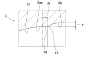
- FIG. 2A is an enlarged sectional view of the outer member 2
- FIG. 2B is an enlarged view of section B in FIG. 2A
- the outer member 2 has a straight portion 14 in a portion adjacent to the second step 12 in the raceway groove 2a.
- the straight portion 14 extends in the axial direction from the groove bottom 2aa of the raceway groove 2a toward the second step 12.
- the straight portion 14 is a range indicated by R in FIG. 2A.
- the groove bottom 2aa of the raceway groove 2a is the most recessed part of the raceway groove 2a, that is, the part with the largest diameter.
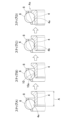
- FIG. 3 shows the procedure for assembling the retainer 8 and balls 6 to the inner member 4.
- step (A) of FIG. 3 the ball 6 is placed on the small diameter portion 4e of the inner member 4. In this state, there is a pocket gap between the cage 8 and the balls 6, and the cage 8 is not elastically deformed.
- step (B) of FIG. 3 the ball 6 is placed on the inclined surface 10a of the first step 10 of the inner member 4. In this state, the pocket clearance is gradually decreasing.
- step (C) of FIG. 3 the ball 6 is placed on the counterbore portion 4b of the inner member 4. In this state, there is no pocket gap between the cage 8 and the balls 6, and the cage 8 is elastically deformed.
- Step (D) in FIG. 3 is a state in which the balls 6 have passed over the counterbore 4b and fitted into the raceway grooves 4a, that is, the inner member 4, the balls 6, and the assembly parts As of the retainer 8 have been completed. . In this state, there is a pocket gap between the retainer 8 and the balls 6.
- step (C) in FIG. 3 If the state of step (C) in FIG. 3 is long, the elastic range of the retainer 8 will be exceeded, making assembly difficult. Alternatively, the cage 8 may be plastically deformed, and even if it gets over the counterbore portion 4b, it may come off.
- the axial dimension Z of the counterbore portion 4b of the inner member 4 is set to 8 to 20% of the diameter Dw of the ball 6.
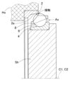
- FIG. 4A and 4B show a state in which the outer member 2 is assembled into the assembly part
- FIG. 4A shows a bearing of this embodiment in which the outer member 2 has a counterbore portion 2b
- FIG. 4B shows a bearing of a comparative example in which the outer member 2 does not have a counterbore portion 2b.
- the second step 12 of the counterbore 2b of the outer member 2 plays the role of a spigot, so the balls 6 can be guided to the raceway groove 2a. Furthermore, since the outer member 2 has the counterbore 2b, there is play between the center C1 of the inner diameter of the inner member 2 and the center C2 of the outer diameter of the outer member, making it easy to assemble.
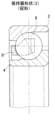
- the cage shape (1) in FIG. 5A is the same annular cage as in the above embodiment.
- the cage shape (2) in FIG. 5B is a crown-shaped cage made of synthetic resin.
- the cage shape (3) in FIG. 5C is an iron plate-shaped cage.
- cage 8 having cage shape (1) is used.
- cage 8 having cage shape (2) is used.
- cage 8 having cage shape (3) is used.
- PA66+GF30% (30% glass-filled nylon 66) was selected as a representative example of a soft material
- PA9T+GF30% (30% glass-filled polyamide 9T) was selected as a representative example of a hard material.
- a steel plate (SPCC) cage was comparatively evaluated.
- a cage 8 made of PA66+GF30% is used.
- a cage 8 made of PA9T+GF30% is used.
- a cage 8 made of steel plate (SPCC) is used.
- ⁇ in Table 1 indicates that it is possible to implement and has a high effect. “ ⁇ ” indicates that the performance is inferior to “ ⁇ ”, but it can be implemented. “ ⁇ ” indicates that the performance is inferior to “ ⁇ ”, but it can be implemented. “x” indicates that the effect is low.
- the height X of the first step 10 of the inner member 4 is 0.1 to 0.5% of the pitch circle diameter of the ball, and the height
- the axial dimension Z is 0.1 to 0.5% of the pitch circle diameter of the ball
- the height By setting the axial dimension Z to 8 to 20% of the diameter Dw of the balls 6, assembly can be performed regardless of the shape of the cage and the material of the cage. Furthermore, by setting the radial distance Z from the groove bottom 4aa of the raceway groove 4a of the inner member 4 to the counterbore portion 4b to 0.2 to 0.7% of the pitch circle diameter P of the ball 6, the The inner member 4 becomes difficult to disassemble, and workability is improved.
- Examples 2, 4, and 5 in which the retainer 8 was made of a hard material were also excellent in both ease of assembly and ease of handling after installation.
- Comparative Example 1 using the soft cage 8 it was possible to assemble and the handling was not bad, but the effect was inferior to Examples 1 to 5.
- Comparative Examples 2 and 3 in which the cage 8 was made of a hard material no effect was observed in terms of both ease of assembly and ease of handling.
- the first step 10 is provided in the counterbore portion 4b of the inner member 4 shown in FIG. 1, when the retainer 8 and balls 6 shown in FIG. 4e to guide the ball 6 and retainer 8 to the counterbore portion 4b, making it easy to assemble the balls 6 and retainer 8 into the inner member 4. That is, the height X of the first step 10 of the inner member 4 in FIG. 1 is set to 0.1 to 0.5% of the pitch circle diameter P of the ball 9, and By setting the dimension Z to 8 to 20% of the diameter Dw of the balls 6, it becomes easy to assemble the retainer 8 and the balls 6 to the inner member 4.
- the retainer 8 and the balls 6 can smoothly overcome the counterbore portion 4b of the inner member 4, improving ease of assembly.
- the outer member 2 has a second step 12 on its inner peripheral surface, and the height Y of the second step 12 is 0.1 to 0.5% of the pitch circle diameter P of the ball 6.
- the counterbore portion 2b of the outer member 2 plays the role of a spigot and guides the ball 6 to the raceway groove 2a, making it easy to assemble.
- the outer member 2 has the counterbore 2b, there is play between the center C1 of the inner diameter of the inner member 2 and the center C2 of the outer diameter of the outer member, making it easy to assemble.
- the outer member 2 has a straight portion 14, which is connected to the second step 12 of the counterbore portion 2b. Thereby, the ball 6 can be separated without getting caught, and the outer member 2 can be smoothly incorporated into the assembly part As. Therefore, the ease of assembling the bearing is improved.
- the present invention is not limited to the above embodiments, and various additions, changes, or deletions can be made without departing from the gist of the present invention. Therefore, such materials are also included within the scope of the present invention.
Landscapes
- Engineering & Computer Science (AREA)
- General Engineering & Computer Science (AREA)
- Mechanical Engineering (AREA)
- Rolling Contact Bearings (AREA)
Abstract
Description

2 外方部材
2a 外方部材の軌道溝
4 内方部材
4a 内方部材の軌道溝
4aa 内方部材の軌道溝の溝底
4b 内方部材のカウンタボア部
6 ボール
8 保持器
10 第1の段差
10a 傾斜面
12 第2の段差
14 ストレート部
As アッシー部品
Dw ボールの直径
M 径方向距離
P ボールのピッチ円径
X 第1の段差の高さ
Y 第2の段差の高さ
Z 内方部材のカウンタボア部の軸方向寸法
Claims (4)
- 外方部材と、内方部材と、前記外方部材と前記内方部材との間に介在された転動体であるボールと、前記ボールを保持する保持器とを備え、前記内方部材、前記ボールおよび前記保持器からなるアッシー部品から前記外方部材が着脱可能なアンギュラ玉軸受であって、
前記内方部材の軌道溝の溝底から内方部材のカウンタボア部までの径方向距離Mが、前記ボールのピッチ円径の0.2~0.7%であり、
前記内方部材のカウンタボア部の軸方向寸法Zが前記ボールの直径Dwの8~20%であり、
前記内方部材は、その外周面に、前記内方部材のカウンタボア部に隣接して前記内方部材のカウンタボア部より縮径する第1の段差を有し、
前記第1の段差の高さXが、前記ボールのピッチ円径の0.1~0.5%であるアンギュラ玉軸受。 - 請求項1に記載のアンギュラ玉軸受において、前記第1の段差が傾斜面であるアンギュラ玉軸受。
- 請求項1または2に記載のアンギュラ玉軸受において、前記外方部材は、その内周面に、前記外方部材の軌道溝に隣接して前記外方部材の軌道溝より拡径する第2の段差を有し、
前記第2の段差の高さYが前記ボールのピッチ円径の0.1~0.5%であるアンギュラ玉軸受。 - 請求項3に記載のアンギュラ玉軸受において、前記外方部材は、前記外方部材の軌道溝における前記第2の段差に隣接する部分にストレート部を有するアンギュラ玉軸受。
Priority Applications (1)
| Application Number | Priority Date | Filing Date | Title |
|---|---|---|---|
| CN202380030024.9A CN118922642A (zh) | 2022-03-29 | 2023-03-23 | 角接触球轴承 |
Applications Claiming Priority (2)
| Application Number | Priority Date | Filing Date | Title |
|---|---|---|---|
| JP2022-053404 | 2022-03-29 | ||
| JP2022053404A JP7824803B2 (ja) | 2022-03-29 | 2022-03-29 | アンギュラ玉軸受 |
Publications (1)
| Publication Number | Publication Date |
|---|---|
| WO2023190028A1 true WO2023190028A1 (ja) | 2023-10-05 |
Family
ID=88202045
Family Applications (1)
| Application Number | Title | Priority Date | Filing Date |
|---|---|---|---|
| PCT/JP2023/011488 Ceased WO2023190028A1 (ja) | 2022-03-29 | 2023-03-23 | アンギュラ玉軸受 |
Country Status (3)
| Country | Link |
|---|---|
| JP (1) | JP7824803B2 (ja) |
| CN (1) | CN118922642A (ja) |
| WO (1) | WO2023190028A1 (ja) |
Citations (3)
| Publication number | Priority date | Publication date | Assignee | Title |
|---|---|---|---|---|
| JP2001193745A (ja) * | 2000-01-11 | 2001-07-17 | Ntn Corp | 車輪軸受装置 |
| JP2014169777A (ja) * | 2013-03-05 | 2014-09-18 | Nsk Ltd | 複列アンギュラ玉軸受ユニット |
| JP2016200240A (ja) * | 2015-04-13 | 2016-12-01 | 株式会社ジェイテクト | 深溝玉軸受 |
-
2022
- 2022-03-29 JP JP2022053404A patent/JP7824803B2/ja active Active
-
2023
- 2023-03-23 CN CN202380030024.9A patent/CN118922642A/zh active Pending
- 2023-03-23 WO PCT/JP2023/011488 patent/WO2023190028A1/ja not_active Ceased
Patent Citations (3)
| Publication number | Priority date | Publication date | Assignee | Title |
|---|---|---|---|---|
| JP2001193745A (ja) * | 2000-01-11 | 2001-07-17 | Ntn Corp | 車輪軸受装置 |
| JP2014169777A (ja) * | 2013-03-05 | 2014-09-18 | Nsk Ltd | 複列アンギュラ玉軸受ユニット |
| JP2016200240A (ja) * | 2015-04-13 | 2016-12-01 | 株式会社ジェイテクト | 深溝玉軸受 |
Also Published As
| Publication number | Publication date |
|---|---|
| JP7824803B2 (ja) | 2026-03-05 |
| JP2023146290A (ja) | 2023-10-12 |
| CN118922642A (zh) | 2024-11-08 |
Similar Documents
| Publication | Publication Date | Title |
|---|---|---|
| CN104246252B (zh) | 柔性轴承罩 | |
| US20110142389A1 (en) | Tapered roller bearing resin cage and tapered roller bearing | |
| US20110116734A1 (en) | Punched retainer, self-aligning roller bearing, and method of manufacturing punched retainer | |
| JP5597410B2 (ja) | 分割型保持器のセグメント及び転がり軸受 | |
| TWI776014B (zh) | 滾球軸承保持架及滾球軸承 | |
| WO2012039282A1 (ja) | 転がり軸受 | |
| JP2006144839A (ja) | ころ軸受 | |
| KR20220137079A (ko) | 볼 베어링용 관형 유지기 및 볼 베어링 | |
| JP2011085219A (ja) | 転がり軸受 | |
| US7364365B2 (en) | Conrad bearing cage | |
| EP3527839A1 (en) | Retainer for angular ball bearings | |
| KR20070084134A (ko) | 롤러 베어링용 케이지 | |
| CN116006646B (zh) | 滚珠丝杠 | |
| JP2006242284A (ja) | 鍔付円筒ころ軸受 | |
| JPWO2013011694A1 (ja) | 転がりねじ用シール及び転がりねじ | |
| US10527096B2 (en) | Rolling bearing | |
| JP2023146290A (ja) | アンギュラ玉軸受 | |
| JP2009275722A (ja) | 転がり軸受 | |
| KR200472196Y1 (ko) | 스러스트 볼 베어링 | |
| JP2008014335A (ja) | 円すいころ軸受 | |
| WO2014062108A1 (en) | Roller bearing and method for assembling a roller bearing | |
| JP2021101119A (ja) | ころ軸受 | |
| JP2009052616A (ja) | 転がり軸受 | |
| JP5071775B2 (ja) | 2分割外輪及びそれを用いたころ軸受 | |
| EP4112956B1 (en) | Cylindrical roller bearing with outer ring |
Legal Events
| Date | Code | Title | Description |
|---|---|---|---|
| 121 | Ep: the epo has been informed by wipo that ep was designated in this application |
Ref document number: 23780039 Country of ref document: EP Kind code of ref document: A1 |
|
| WWE | Wipo information: entry into national phase |
Ref document number: 202380030024.9 Country of ref document: CN |
|
| WWE | Wipo information: entry into national phase |
Ref document number: 202417078911 Country of ref document: IN |
|
| NENP | Non-entry into the national phase |
Ref country code: DE |
|
| 122 | Ep: pct application non-entry in european phase |
Ref document number: 23780039 Country of ref document: EP Kind code of ref document: A1 |