WO2023189483A1 - Peripheral blood pressure estimation method and biological information measurement system - Google Patents
Peripheral blood pressure estimation method and biological information measurement system Download PDFInfo
- Publication number
- WO2023189483A1 WO2023189483A1 PCT/JP2023/009623 JP2023009623W WO2023189483A1 WO 2023189483 A1 WO2023189483 A1 WO 2023189483A1 JP 2023009623 W JP2023009623 W JP 2023009623W WO 2023189483 A1 WO2023189483 A1 WO 2023189483A1
- Authority
- WO
- WIPO (PCT)
- Prior art keywords
- blood pressure
- peripheral blood
- photoplethysmogram
- signal
- pulse wave
- Prior art date
Links
- 230000036772 blood pressure Effects 0.000 title claims abstract description 136
- 210000005259 peripheral blood Anatomy 0.000 title claims abstract description 88
- 239000011886 peripheral blood Substances 0.000 title claims abstract description 88
- 238000005259 measurement Methods 0.000 title claims abstract description 56
- 238000000034 method Methods 0.000 title claims abstract description 28
- 210000002565 arteriole Anatomy 0.000 claims abstract description 39
- 230000002093 peripheral effect Effects 0.000 claims abstract description 35
- 238000012545 processing Methods 0.000 claims description 14
- 230000004069 differentiation Effects 0.000 claims description 12
- 238000003825 pressing Methods 0.000 claims description 6
- 238000001514 detection method Methods 0.000 claims description 4
- 230000001133 acceleration Effects 0.000 description 17
- 210000003491 skin Anatomy 0.000 description 15
- 210000001367 artery Anatomy 0.000 description 8
- 210000004204 blood vessel Anatomy 0.000 description 8
- 230000035488 systolic blood pressure Effects 0.000 description 8
- 210000000707 wrist Anatomy 0.000 description 8
- 210000001015 abdomen Anatomy 0.000 description 7
- 230000008859 change Effects 0.000 description 6
- 230000007423 decrease Effects 0.000 description 6
- 238000004364 calculation method Methods 0.000 description 5
- 238000004891 communication Methods 0.000 description 5
- 238000010586 diagram Methods 0.000 description 5
- 230000017531 blood circulation Effects 0.000 description 4
- 238000001816 cooling Methods 0.000 description 4
- 230000006870 function Effects 0.000 description 4
- 230000000284 resting effect Effects 0.000 description 4
- CVOFKRWYWCSDMA-UHFFFAOYSA-N 2-chloro-n-(2,6-diethylphenyl)-n-(methoxymethyl)acetamide;2,6-dinitro-n,n-dipropyl-4-(trifluoromethyl)aniline Chemical compound CCC1=CC=CC(CC)=C1N(COC)C(=O)CCl.CCCN(CCC)C1=C([N+]([O-])=O)C=C(C(F)(F)F)C=C1[N+]([O-])=O CVOFKRWYWCSDMA-UHFFFAOYSA-N 0.000 description 3
- 210000001061 forehead Anatomy 0.000 description 3
- 210000004247 hand Anatomy 0.000 description 3
- 230000003287 optical effect Effects 0.000 description 3
- 238000012935 Averaging Methods 0.000 description 2
- 210000005069 ears Anatomy 0.000 description 2
- 230000002792 vascular Effects 0.000 description 2
- 206010003210 Arteriosclerosis Diseases 0.000 description 1
- 102000001554 Hemoglobins Human genes 0.000 description 1
- 108010054147 Hemoglobins Proteins 0.000 description 1
- 210000003423 ankle Anatomy 0.000 description 1
- 230000004872 arterial blood pressure Effects 0.000 description 1
- 208000011775 arteriosclerosis disease Diseases 0.000 description 1
- QVGXLLKOCUKJST-UHFFFAOYSA-N atomic oxygen Chemical compound [O] QVGXLLKOCUKJST-UHFFFAOYSA-N 0.000 description 1
- 210000003403 autonomic nervous system Anatomy 0.000 description 1
- 210000004369 blood Anatomy 0.000 description 1
- 239000008280 blood Substances 0.000 description 1
- 238000012937 correction Methods 0.000 description 1
- 210000002615 epidermis Anatomy 0.000 description 1
- 230000001747 exhibiting effect Effects 0.000 description 1
- 230000036541 health Effects 0.000 description 1
- 230000010365 information processing Effects 0.000 description 1
- 238000000691 measurement method Methods 0.000 description 1
- 230000003340 mental effect Effects 0.000 description 1
- 229910052760 oxygen Inorganic materials 0.000 description 1
- 239000001301 oxygen Substances 0.000 description 1
- 230000036513 peripheral conductance Effects 0.000 description 1
- 238000013186 photoplethysmography Methods 0.000 description 1
- 230000008569 process Effects 0.000 description 1
- 230000001902 propagating effect Effects 0.000 description 1
- 230000035485 pulse pressure Effects 0.000 description 1
- 210000002321 radial artery Anatomy 0.000 description 1
- 230000009467 reduction Effects 0.000 description 1
- 230000011514 reflex Effects 0.000 description 1
- 210000003462 vein Anatomy 0.000 description 1
- 230000003442 weekly effect Effects 0.000 description 1
Images


Classifications
-
- A—HUMAN NECESSITIES
- A61—MEDICAL OR VETERINARY SCIENCE; HYGIENE
- A61B—DIAGNOSIS; SURGERY; IDENTIFICATION
- A61B5/00—Measuring for diagnostic purposes; Identification of persons
- A61B5/02—Detecting, measuring or recording pulse, heart rate, blood pressure or blood flow; Combined pulse/heart-rate/blood pressure determination; Evaluating a cardiovascular condition not otherwise provided for, e.g. using combinations of techniques provided for in this group with electrocardiography or electroauscultation; Heart catheters for measuring blood pressure
- A61B5/021—Measuring pressure in heart or blood vessels
- A61B5/022—Measuring pressure in heart or blood vessels by applying pressure to close blood vessels, e.g. against the skin; Ophthalmodynamometers
Definitions
- the present invention relates to a peripheral blood pressure estimation method and biological information measurement system for estimating blood pressure in peripheral capillaries or arterioles of a subject (user).
- Pulse waves propagating within the user's arteries are used as an index used to estimate the user's health condition.
- the pulse wave changes according to changes in the user's blood pressure at the measurement location.
- Patent Document 1 discloses a pulse wave measuring device for measuring blood pressure that places less burden on the living body.
- blood pressure information of a living body is estimated based on the pulse rate of the living body and time information of the pulse wave of the living body.
- the estimation of blood pressure information in the pulse wave measuring device described in Patent Document 1 is performed on arterial blood pressure information, and is not performed on blood pressure information regarding the user's peripheral capillaries or arteriolar movements.
- An object of the present invention is to provide a peripheral blood pressure estimation method and a biological information measurement system that can non-invasively estimate such peripheral blood pressure information.
- the present invention provides acquiring a photoplethysmogram signal from peripheral capillaries or arterioles of the subject with a photoplethysmogram sensor;
- the step of calculating a peripheral blood pressure index which is an index of the blood pressure of peripheral capillaries or arterioles, based on the steepness of the rise of the photoplethysmogram signal, is executed by the biological information measurement system,
- a peripheral blood pressure estimation method for estimating the magnitude of arteriolar blood pressure based on a peripheral blood pressure index was constructed.
- a sensing device having a photoplethysmogram sensor that acquires a photoplethysmogram signal of peripheral capillaries or arterioles of the subject;
- a biological information measuring system is configured, comprising a computer having a signal processing device that calculates a peripheral blood pressure index, which is an index of blood pressure in peripheral capillaries or arterioles, based on the steepness of the rise of a photoplethysmogram signal. .
- a photoplethysmogram signal of a subject's peripheral capillaries or arterioles is acquired by a photoplethysmogram sensor, and based on the steepness of the rise of the acquired photoplethysmogram signal, the subject's peripheral capillaries or arterioles are detected.
- a peripheral blood pressure index is calculated, which is an index of the magnitude of blood pressure in blood vessels or arterioles.
- the magnitude of blood pressure in peripheral capillaries or arterioles of the subject is estimated based on the calculated peripheral blood pressure index.
- the present invention provides a peripheral blood pressure estimation method and a biological information measurement system that can non-invasively and easily estimate the blood pressure of peripheral capillaries or arterioles without burdening the subject. can do.
- FIG. 1 is an explanatory diagram showing the configuration of a biological information measurement system according to an embodiment of the present invention.
- FIG. 1 is an explanatory diagram showing the external configuration of a sensing device according to an embodiment of the present invention. It is an explanatory view showing an example of a user's posture when measuring biological information.
- FIG. 2 is an explanatory diagram schematically showing acquisition of a photoplethysmogram signal by a sensing device according to an embodiment of the present invention. It is a graph explaining the maximum amplitude value of a photoplethysmogram signal. It is a 1st graph explaining each waveform element required for calculation of the pulse wave feature quantity which is the basis of a peripheral blood pressure index.
- FIG. 7 is a graph showing the relationship between systolic blood pressure and each pulse wave feature when the height of the measurement site is changed and when the vicinity of the measurement site is cooled, calculated from a photoplethysmogram signal measured with green light.
- FIG. . A graph showing the relationship between systolic blood pressure and each pulse wave feature when the height of the measurement site is changed and when the vicinity of the measurement site is cooled, calculated from photoplethysmogram signals measured with near-infrared light.
- It is. 3 is a flowchart showing a process flow of a peripheral blood pressure estimation method according to an embodiment of the present invention.
- FIG. 1 is an explanatory diagram showing the configuration of a biological information measurement system 10 related to an embodiment of the present invention.
- the biological information measurement system 10 includes a sensing device 20 that measures biological information of a user who is a subject, and a computer 30 configured to be able to communicate with the sensing device 20.
- the sensing device 20 is, for example, a wearable device that has a structure that can be attached to a user's peripheral site (for example, a finger).
- the sensing device 20 includes a biosensor 21 that measures biometric information from a user's peripheral site (for example, a finger), a control circuit 22 that controls the operation of the biosensor 21, and a control circuit 22 that transmits the measurement results of the sensing device 20 via a wireless line or a wired connection. It includes a communication module 23 that transmits data to the computer 30 through a line, and an acceleration sensor 24 that measures the movement acceleration of the sensing device 20.
- the biosensor 21 includes, for example, a photoplethysmogram sensor 211 that measures an index value indicating the user's peripheral blood pressure.
- Peripheral blood pressure within the present invention is defined as blood pressure in peripheral capillaries and arterioles.
- an index indicating blood pressure in arterioles and capillaries, particularly in capillaries is referred to as a peripheral blood pressure index.
- the arteriole is a small artery with a diameter of, for example, about 20 to 200 ⁇ m, and is a blood vessel that exists between an artery and a capillary.
- a capillary blood vessel is a thin blood vessel with a diameter of about 10 ⁇ m, for example, and is a blood vessel that connects an artery and a vein.
- Peripheral blood pressure is sometimes used to mean wrist blood pressure or ankle blood pressure measured with a cuff-type blood pressure monitor, but in that case, it is a value measured in a large artery (such as the radial artery), and in the present invention Blood pressure in arterioles and capillaries is different. Blood pressure in large arteries is generally measured with a cuff-type sphygmomanometer, and blood pressure in blood vessels decreases as the blood pressure progresses from arteries to arterioles and capillaries. The degree of blood pressure reduction varies depending on the measurement site, the individual's vascular condition (arteriosclerosis, etc.), mental condition (autonomic nervous system, etc.), environment (temperature, noise, etc.), clothing, etc.
- peripheral blood pressure index is approximately proportional to blood pressure (in the upper arm or wrist).
- peripheral blood pressure index decreases. This means increased peripheral vascular resistance, so blood pressure in the upper arm and wrist may increase.
- the photoplethysmogram sensor 211 is equipped with three LEDs as a light source, and measures photoplethysmographic signals at three wavelengths (green, red, and near-infrared). Oxylated hemoglobin exists in the blood of arteries and has the property of absorbing incident light. Therefore, it is possible to measure the blood flow rate (change in blood vessel volume) that changes with the heartbeat over time. By sensing, a photoplethysmogram signal can be measured.
- the red LED is installed for calculating oxygen saturation and is not essential for extracting peripheral blood pressure indicators.
- the photoplethysmographic sensor 211 is equipped with a photodiode (PD) as a light-receiving element, and the three LEDs emit light in sequence in a time-sharing manner to illuminate the skin of the finger, and the PD receives the reflected and scattered light that returns. do.
- PD photodiode
- the communication module 23 transmits the measurement results of the sensing device 20 (for example, the photoplethysmogram signal measured by the photoplethysmographic sensor 211 and the acceleration of the sensing device 20 measured by the acceleration sensor 24) through a wireless line or a wired line. to the computer 30.
- the sensing device 20 for example, the photoplethysmogram signal measured by the photoplethysmographic sensor 211 and the acceleration of the sensing device 20 measured by the acceleration sensor 24
- the acceleration sensor 24 measures the movement acceleration of the sensing device 20 when the user changes his or her posture to measure the pulse wave signal.
- the acceleration sensor 24 is a three-axis acceleration sensor that detects the direction in which gravitational acceleration is applied, and its detection signal is used to estimate the height at which the user is attaching the sensing device 20 and to estimate the height at which the user attaches the sensing device 20. Estimating the position (e.g., the position of the user's heart) or the user's posture, e.g., standing (standing), sitting (sitting), or lying on the back (supine). Used for estimation.
- the computer 30 is, for example, a multifunctional mobile phone called a smartphone, or a general-purpose computer (eg, a notebook computer, a desktop computer, a tablet terminal, a server computer, etc.).
- the computer 30 includes a communication module 31 that receives the measurement results of the biosensor 21 from the sensing device 20 via a wireless line or a wired line, and a signal processing device that performs processing to estimate the user's biometric information from the measurement results of the biosensor 21.
- the signal processing device 32 includes a processor 321, a memory 322, and an input/output interface 323.
- the signal processing device 32 performs first-order differentiation (velocity pulse wave) and second-order differentiation (acceleration pulse wave) of the two photoplethysmograms (volume pulse wave) measured by the green LED and the near-infrared LED, and calculates each of them by 1 Calculate pulse wave features by dividing each beat. Then, a peripheral blood pressure index is calculated based on the pulse wave feature amount. Further, the signal processing device 32 estimates the height of the part to which the user attaches the sensing device 20 and the user's posture based on the signal from the acceleration sensor 24 .
- FIG. 2 is an explanatory diagram showing the external configuration of the sensing device 20 according to the embodiment of the present invention.
- Sites for measuring photoplethysmograms include the wrist, neck, face, and ears, but fingers are preferred. The reason why fingers are preferable is because their epidermis is relatively thin, making it easy to measure photoplethysmograms, and because the capillary paths are less complex than those on the face, the values of each feature are likely to be stable. .
- a ring-shaped wearable device that is equipped with an optical sensor and is worn on a finger is suitable. This is because when measuring continuously or intermittently, there is little discomfort or discomfort even when worn for a long time.
- wearable devices can include wristbands worn on the wrist, wristwatches, earphones worn in the ears, patches attached to the skin, and neckbands worn around the neck. It's okay. Further, it does not need to be a wearable device, and may be a portable type such as a smartphone or an installed type, and may be configured to measure by placing a finger on a sensor.
- the sensing device 20 includes a ring-shaped housing 25 that is configured to be attachable to a user's finger.
- the housing 25 has a hollow cylindrical shape.
- the biosensor 21 is attached to the inner peripheral surface of the housing 25 (the inner surface of the hollow cylinder) so that the pad of the user's finger faces the biosensor 21 when the sensing device 20 is attached to the user's finger.
- the shape of the housing 25 is not limited to a hollow cylindrical shape, and may be, for example, a cylindrical shape that fits into the user's finger (for example, the shape of a finger cot). may or may not be present.
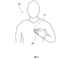
- FIG. 3 is an example of the posture of the user 40 when measuring biological information.
- the user 40 is in a state where the finger on which the sensing device 20 is attached is stationary at the position of the heart 41, and the sensing device 20 is measuring biological information from the user's 40 finger.
- the position (measurement position) of the sensing device 20 when measuring biological information is not limited to the position of the chest (heart) 41 of the user 40, but may also be the position of the face (forehead) or the position of the abdomen (navel) of the user 40. But that's fine.
- the posture of the user 40 when measuring biological information may be a sitting posture or a supine posture.
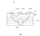
- FIG. 4 is a schematic cross-sectional view of the biosensor 21 attached close to the body surface S of the user.
- the biosensor 21 has light emitting elements 211a, 211b and a light receiving element 211c.
- the biosensor 21 irradiates light onto the body surface S, and receives light absorbed or reflected by the user's epidermal region EP, a plurality of capillaries CA, and arterioles AR that are the branching sources of each capillary CA. do.
- one light receiving element 211c is provided for each light emitting element 211a, 211b serving as a light source.
- a light receiving element may be provided for each of the light emitting elements 211a and 211b.
- the light emitting element 211a is preferably an LED or a laser having a wavelength in the vicinity of blue to yellowish green (preferably a wavelength in the vicinity of 500 to 550 nm), and in this embodiment, it is a green LED.
- the light emitting element 211b is preferably an LED or a laser having a wavelength in the vicinity of red to near infrared (preferably a wavelength in the vicinity of 750 to 950 nm), and in this embodiment, it is a near infrared LED.
- the light emitting element 211a emits light in a wavelength range that is strongly absorbed in the living body, and the light emitting element 211b emits light in a wavelength range that is relatively weakly absorbed in the living body.
- the light emitting element 211a will be described as a green LED 211a, and the light emitting element 211b will be described as a near-infrared LED 211b.
- the light receiving element 211c uses a photodiode (PD) or a phototransistor. A Si photodiode is preferred.
- the green LED 211a is provided at a position closer to the light receiving element 211c than the near-infrared LED 211b.
- the distance between the green LED 211a and the light receiving element 211c be about 1 to 3 mm
- the distance between the near infrared LED 211b and the light receiving element 211c be about 5 to 20 mm.
- the light emitted from the green LED 211a is absorbed by the user's epidermal region EP and the capillaries CA on the epidermal region EP side, and the transmitted light or reflected light is detected by the light receiving element 211c.
- the light emitted from the near-infrared LED 211b is absorbed by the user's epidermal region EP, capillaries CA, and arterioles AR located inside the body from the epidermal region EP, and detected by the light receiving element 211c.
- the light from the green LED 211a is schematically shown as light along the optical path P1
- the light from the near-infrared LED 211b is schematically shown as the light along the optical path P2.
- the pulse wave features showing the characteristics (1) and (2) above of the peripheral blood pressure index were extracted using the following method. That is, a finger-mounted sensing device 20 shown in FIG. 2 equipped with a photoplethysmographic sensor 211 is prepared, a wrist-type cuff blood pressure monitor is attached to the left wrist of the user 40 (the right hand is also acceptable), and the index finger of the same left hand ( This sensing device 20 was attached to the user's finger (another finger may also be used). Then, in a resting sitting position, the left hand with the sensing device 20 attached was held at the level of the abdomen (belly button), the chest level, and the face (forehead) level, and the photoelectric pulse and blood pressure were measured.
- the characteristic amounts of the pulse waves showing the characteristics (1) and (2) above of the peripheral blood pressure index were calculated as follows.
- the graph in FIG. 5 shows an accelerated pulse wave signal 52 obtained by second-order differentiation of a photoplethysmogram (photoplethysmogram) signal 53.
- the horizontal axis of the graph represents time [sec], and the vertical axis represents the signal strength of the accelerated pulse wave signal 52 and the photoplethysmogram signal 53.
- the photoplethysmogram signal 53 connects the minimum points with a straight line, and after performing slope correction so that the slope of the straight line becomes 0, the height of the maximum point is calculated as the pulse wave height (maximum amplitude). Value) S.
- the waveform width at half the maximum peak value of the velocity pulse wave signal 51 obtained by first-order differentiation of the photoplethysmogram signal 53 is called VE0.5.
- the horizontal axis of the graph represents time [sec]
- the vertical axis represents the signal intensities of the velocity pulse wave signal 51, the acceleration pulse wave signal 52, and the photoplethysmogram signal 53.
- the velocity pulse wave signal 51 and the acceleration pulse wave signal 52 are normalized so that their maximum values are set to 1.
- the peaks (maximum peak and minimum peak) of the accelerated pulse wave signal 52 are called a-wave, b-wave, c-wave, d-wave, and e-wave, respectively, as shown in the figure.
- the a-wave, c-wave, and e-wave have a convex peak on the positive side, and the b-wave and d-wave have a convex peak on the negative side. Further, the difference between the a-wave peak time and the b-wave peak time is referred to as the ab time. Furthermore, the signal intensities at the respective peaks of the a-wave, b-wave, c-wave, d-wave, and e-wave are assumed to be a, b, c, d, and e. Further, as shown in the graph of FIG.
- the peak difference between the a-wave and the b-wave of the accelerated pulse wave signal 52 is designated as a-b
- the peak difference between the a-wave and the d-wave is designated as ad.
- the horizontal and vertical axes of the graph are the same as the graph of FIG. 6.
- pulse wave features were extracted as pulse wave features that exhibit the feature (1) above that the peripheral blood pressure index is approximately proportional to the blood pressure in the upper arm or wrist. ⁇ 1/VE0.5 ⁇ a/S ⁇ (a-b)/(a-d)
- FIG. 8(a) is a graph showing two photoplethysmogram signals 53a and 53b having different steepness of rise of the photoplethysmogram waveform.
- the horizontal axis of the graph is time [sec]
- the vertical axis is the signal intensity of the photoplethysmogram signal 53. It can be seen that of these two photoplethysmogram signals 53a and 53b, the photoplethysmogram signal 53a shown by the solid line has a steeper rise (slope: larger) than the photoplethysmogram signal 53b shown by the broken line.
- the graph shown in FIG. 8(b) shows changes in the values of the pulse wave feature quantity 1/VE0.5 and the pulse wave feature quantity a/S due to the difference in slope of the photoplethysmogram signals 53a and 53b. ing.
- the vertical axis of the graph represents each value of the pulse wave feature 1/VE0.5 and the pulse wave feature a/S, and the horizontal axis represents the photoplethysmogram signal 53b with a small slope and the photoplethysmogram signal with a large slope. 53a.
- both the pulse wave feature amount 1/VE0.5 and the pulse wave feature amount a/S are the photoplethysmogram signal 53a with a large slope, and the photoplethysmogram signal with a small slope. It can be seen that the value is larger than that of each pulse wave characteristic amount for 53b.
- the graph shown in FIG. 8(c) shows each pulse wave feature amount (ab)/(ad) and pulse wave feature amount 1/ab time due to the difference in slope of the photoplethysmogram signals 53a and 53b.
- the change in value is shown.
- the vertical axis of the graph represents each value of the pulse wave feature amount (a-b)/(a-d) and the pulse wave feature amount 1/ab time, and the horizontal axis represents the photoplethysmogram signal 53b with a small slope. It is divided into a photoplethysmogram signal 53a with a large slope.
- the three pulse wave feature values 1/VE0.5, a/S and (a-b)/(a-d) mentioned above are related to the steepness of the rise of the photoplethysmogram waveform.
- the steepness of the rise of the photoplethysmogram waveform can be expressed by these pulse wave feature quantities, and these pulse wave feature quantities are assumed to be pulse wave feature quantities exhibiting the feature (1) above.
- the pulse wave feature 1/ab time is added for comparison as another feature related to the steepness of the rise of the photoplethysmogram waveform.
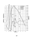
- Figures 9 and 10 show the systolic blood pressure and each pulse wave feature when changing the height of the measurement site (finger) from the heart, measured using the measurement method described above, and the measurement at chest height.
- the relationship between the systolic blood pressure and each pulse wave feature when cooling the area near the elbow of the arm on the side where the finger is located is shown.
- FIGS. 9(a), (b), (c) and (d) are pulse wave feature values 1/VE0.5, a/S, (ab)/(ad) and 1, respectively.
- the results calculated from the photoplethysmogram signal measured using green light emitted from the green LED 211a with respect to the /ab time are shown.
- each of these graphs is the systolic blood pressure [mmHg] measured at the wrist, and the vertical axis is the magnitude of each pulse wave feature.
- the measurements were performed on three users A, B, and C, and the characteristic line A obtained by connecting the triangular plots is for user A, the characteristic line B obtained by connecting the circular plots is for user B, and the characteristic line B obtained by connecting the circular plots is for user B.
- a characteristic line C obtained by connecting the plots of 2 and 3 shows the measurement results for user C when the height of the measurement site (finger) from the heart is changed.
- each plot drawn out with a broken line shows the measurement results when cooling the measurement site near the elbow of the arm on the side where the finger is located at the height of the chest.
- the pulse wave feature values shown in FIGS. 9(a), (b), and (c) calculated from the photoplethysmogram signal measured with green light are different when the height of the measurement site (finger) from the heart is changed. It can be seen from the characteristic lines A, B, and C that the systolic blood pressure and each pulse wave characteristic amount tend to be nearly proportional. As the height of the measurement site (finger) from the heart increases in the abdomen, chest, and face, each pulse wave feature becomes smaller, and the systolic blood pressure decreases almost in proportion. Moreover, when the vicinity of the measurement site is cooled, the magnitude of each pulse wave feature decreases and the systolic blood pressure tends to increase, which can be confirmed from each plot drawn out with a broken line. This is consistent with the above-mentioned characteristics (1) and (2) of the assumed peripheral blood pressure index.
- the 1/ab time pulse wave feature shown in FIG. 9(d) has a tendency that is not as clear as the pulse wave feature shown in FIGS. 9(a), (b), and (c).
- the calculation results of each pulse wave feature shown in FIGS. 10(a), (b), (c), and (d) calculated from photoplethysmogram signals measured almost simultaneously with near-infrared light and green light are , it can be seen that the above-mentioned tendency is not clear when compared with the results calculated from green light.
- features (1) and (2) of the peripheral blood pressure index are more applicable to each pulse wave feature obtained with green light. This is because green light has a high bioabsorbance and is absorbed before it reaches deep skin areas, so it only contains information about shallow skin areas. Since the information that is measured is only for shallow areas of the skin, the information contained in the green light photoplethysmogram signal is mainly for capillaries. Therefore, the large amount of capillary information is thought to be the reason why each pulse wave feature shown in Figures 9(a), (b), and (c) exhibits characteristics (1) and (2) of the peripheral blood pressure index. .
- an LED or laser with a wavelength in the blue to yellowish green range (preferably in the vicinity of 500 to 550 nm), which is highly absorbed by the body, is used as the light source of the photoplethysmogram sensor 211.
- the distance between the light source and the light receiver is preferably short, specifically 1 to 3 mm.
- the first is the height of the measurement site from the heart.
- the peripheral blood pressure index changes depending on the height from the heart as shown in FIGS. 9 and 10. If you want to observe daily, weekly, or monthly fluctuations, you need to align the measurement conditions. It is desirable to measure at the height of the heart (chest), but it does not have to be at the heart level as long as the height from the heart is constant.
- a posture in which the user is in a sitting position and holds the biosensor 21 with his hands at chest height A posture in which the user is in a sitting position and holds the biosensor 21 with the hand at the height of the face; a posture in which the user is in a sitting position and holds the biosensor 21 with his hands at belly level; a posture in which the user holds the biosensor 21 with his hands at chest height while lying supine on a flat surface;
- the posture in which the user lies supine on a flat surface and holds the biosensor 21 with the hand at the height of the flat surface is a posture that anyone can easily take, and is highly reproducible for individuals. has a high attitude.
- the "belly” is limited to “belly button” and the face is limited to “forehead”, repeatability becomes even higher, and measurement variations in photoplethysmogram signals can be reduced.
- the peripheral blood pressure index will not be stable unless each pulse wave feature amount that serves as the peripheral blood pressure index is measured in a resting state. This is mainly due to two factors: physiological reactions such that the pulse rate and blood pressure are not stabilized for more than 10 to several tens of seconds after movement, and the relative position of the biosensor 21 and the skin is misaligned.
- physiological reactions such that the pulse rate and blood pressure are not stabilized for more than 10 to several tens of seconds after movement, and the relative position of the biosensor 21 and the skin is misaligned.
- the heart rate increases for 10 to several tens of seconds even when the person moves slightly to sit upright. After exercise, it may take several tens of minutes to reach a resting state.
- the latter is called body movement noise, and is unavoidable when the body moves violently, but it subsides as soon as the body stops moving.
- the sensing device 20 is equipped with an acceleration sensor 24 and a gyro sensor, and for example, it is determined that if the acceleration is smaller than a threshold value for a certain period of time, the state is at rest, and the photoplethysmogram is detected when the rest state is maintained. It is preferable to use signals.
- the sensing device 20 has a function of detecting excessive pressure.
- the function of detecting excessive pressure may be realized by a piezoelectric sensor, a pressure sensor, etc., or may be detected from the waveform shape of the photoplethysmogram.
- the peripheral blood pressure index changes depending on the relative height of the sensing device 20 with respect to the heart. Therefore, in the biological information measurement system 10, the computer 30 has a function of determining the height of the sensing device 20 from the heart, and calculates a peripheral blood pressure index when the sensing device 20 is at the height of the user's heart. You can do it like this. Thereby, the relative height of the sensing device 20 with respect to the heart can be limited, so that the peripheral blood pressure can be estimated while suppressing the influence of changes in the peripheral blood pressure index caused by differences in relative height.
- the computer 30 may have a function of estimating the amount of change in the height of the sensing device 20 based on information from the acceleration sensor 24 of the sensing device 20.
- the computer 30 may estimate the peripheral blood pressure based on the peripheral blood pressure index and the amount of change in height.
- the computer 30 can correct the influence of height fluctuations on the peripheral blood pressure index based on the amount of change in the height of the sensing device 20 that affects the peripheral blood pressure index. This improves the estimation accuracy of peripheral blood pressure.
- the height of the sensing device 20 may be input from the outside through the computer 30.
- FIG. 11 is a flowchart illustrating an example of processing in the peripheral blood pressure estimation method according to the embodiment of the present invention.
- the processing by the biological information measurement system 10 is performed by, for example, a program stored in a non-temporary storage area of each of the sensing device 20 and the computer 30, which is executed by the sensing device 20 and the computer 30, which are equipped with an information processing device such as a processor. It is done by being done.
- the sensing device 20 of the biological information measurement system 10 measures a photoplethysmogram signal from the finger of the user wearing the sensing device 20.
- the photoplethysmogram sensor 211 measures the photoplethysmographic signal 53 using green light emitted from the green LED 211a, and also measures the photoplethysmographic signal 53 using near-infrared light emitted from the near-infrared LED 211b.
- step S1102 the sensing device 20 transmits the measurement results to the computer 30 of the biological information measurement system 10.
- step S1103 the computer 30 receives the measurement results of the sensing device 20.
- step S1104 the computer 30 calculates the user's peripheral blood pressure index.
- the computer 30 calculates the pulse wave feature quantity 1/VE0.5, a/S and (ab)/(ad) from the photoplethysmogram signal 53 measured by the biosensor 21, and The user's peripheral blood pressure index is calculated from the wave feature amount.
- step S1105 the computer 30 estimates the user's peripheral blood pressure based on the peripheral blood pressure index stored in a storage unit such as the memory 322.
- the peripheral blood pressure estimation method described in this embodiment includes the steps of acquiring a photoplethysmogram signal 53 of peripheral capillaries or arterioles of a user who is a subject with a photoplethysmogram sensor 211, and a rise of the photoplethysmogram signal 53.
- the biological information measuring system 10 calculates a peripheral blood pressure index that is an index of the blood pressure of peripheral capillaries or arterioles based on the steepness of the blood pressure of peripheral capillaries or arterioles. Estimate the size of the blood pressure based on the peripheral blood pressure index.
- the photoplethysmogram signal 53 of the peripheral capillaries or arterioles of the user is acquired by the photoplethysmogram sensor 211, and based on the steepness of the rise of the acquired photoplethysmogram signal 53, the user's A peripheral blood pressure index, which is an index of the blood pressure of peripheral capillaries or arterioles, is calculated. The magnitude of blood pressure in the user's peripheral capillaries or arterioles is estimated based on the calculated peripheral blood pressure index.
- the steepness of the rise of the photoplethysmogram signal 53 is the width at half the peak value of the waveform of the velocity pulse wave signal 51 obtained by first-order differentiation of the photoplethysmogram signal 53. It is expressed as the reciprocal number 1/VE0.5.
- the peripheral blood pressure index is calculated based on the pulse wave feature amount 1/VE0.5, and becomes an index that is not easily influenced by noise or individual differences in the photoplethysmogram waveform. , it is possible to estimate with less influence of noise and individual differences.
- the steepness of the rise of the photoplethysmogram signal 53 is such that the peak value a of the a-wave of the accelerated pulse wave signal 52 obtained by second-order differentiation of the photoplethysmogram signal 53 is determined by It is expressed as a value a/S divided by the maximum amplitude value S of the wave signal 53.
- the peripheral blood pressure index is calculated based on the pulse wave feature amount a/S. Therefore, a peripheral blood pressure index, which is an index of the blood pressure of the user's peripheral capillaries or arterioles, can be calculated using a simple calculation method.
- the steepness of the rise of the photoplethysmogram signal 53 is determined by the a-wave, b-wave, c-wave and It is expressed as a value calculated by the equation (ab)/(ad), where each peak value of the d wave is a, b, c, and d, respectively.
- the peripheral blood pressure index is calculated based on the pulse wave feature amount (ab)/(ad). Therefore, also with this configuration, it is possible to calculate the peripheral blood pressure index, which is an index of the blood pressure of the user's peripheral capillaries or arterioles, using a simple calculation method.
- pulse wave feature values 1/VE0.5, a/S and (ab)/(ad), which are the basis of the peripheral blood pressure index, may be used alone, but they can also be used for a-wave, b-wave.
- the peak values a, b, c, and d of the c-wave and d-wave are easily influenced by the pressure state of the pulse wave sensor 211 on the skin and body movement noise, and have large variations due to individual differences. Therefore, among the above pulse wave features, 1/VE0.5 is a feature that can be obtained relatively stably, so it is recommended to use 1/VE0.5 alone or based on 1/VE0.5. It is desirable to use other features auxiliary. Further, a value obtained by weighting each of these pulse wave feature amounts and averaging processing may be used, or a value obtained by normalizing the magnitude of each pulse wave feature amount and averaging processing may be used.
- the photoplethysmographic sensor 211 emits light in the blue to yellow-green wavelength range from the light source.
- the photoplethysmogram sensor 211 acquires the photoplethysmogram signal 53 that includes a lot of information about the shallow biological region from the skin surface of the living body. Therefore, it is possible to accurately estimate the blood pressure of peripheral capillaries or arterioles in biological regions with shallow skin.
- the distance between the light source and the light receiving element that receives the reflected light of the light emitted from the light source of the photoplethysmographic sensor 211 is set to 1 to 3 [mm].
- the distance between the light source and the light receiving element of the photoplethysmographic sensor 211 is such that the light emitted from the light source and scattered and reflected by peripheral capillaries or arterioles is sufficiently received by the light receiving element. Set to distance. Therefore, it is possible to estimate the blood pressure of peripheral capillaries or arterioles in shallow biological regions of the skin with higher accuracy.
- the photoplethysmographic sensor 211 is mounted on the sensing device 20 that is worn on the user's finger.
- the photoplethysmogram sensor 211 mounted on the sensing device 20 can stably acquire the photoplethysmogram signal 53 continuously or intermittently from the user's finger. Therefore, the blood pressure of the user's peripheral capillaries or arterioles can be stably estimated.
- the above peripheral blood pressure estimation method may further include a step of detecting a pressing state of the user's measurement site from the photoplethysmographic sensor 211.
- the sensing device 20 includes a pressure state detection sensor composed of, for example, a piezoelectric element, which detects the state of pressure applied by the photoplethysmographic sensor 211 to the measurement site of the subject.
- the signal processing device 32 determines the validity of the estimated peripheral blood pressure index based on the detected pressing state.
- the photoplethysmographic sensor 211 In order to stably measure the photoplethysmogram signal 53, the photoplethysmographic sensor 211 needs to be in close contact with the user's skin at the measurement site; If it is in an excessive state, blood flow will be obstructed and the accuracy of estimating peripheral blood pressure will decrease.
- the pressing state from the photoplethysmographic sensor 211 to the measurement site of the user is detected. It is possible to detect an excessive state and take measures such as not using the estimated peripheral blood pressure value at that time.
Abstract
Provided are a peripheral blood pressure estimation method and a biological information measurement system with which it is possible to non-invasively and conveniently estimate the magnitude of the blood pressure in peripheral capillaries or arterioles. The biological information measurement system 10 executes: a step for acquiring, by means of a photoelectric pulse wave sensor 211, a photoelectric pulse wave signal 53 for the peripheral capillaries or arterioles of a user who is a subject; and a step for calculating, on the basis of the steepness by which the photoelectric pulse wave signal 53 rises, a peripheral blood pressure index serving as an index for the magnitude of the blood pressure in the peripheral capillaries or arterioles. The magnitude of the blood pressure in the peripheral capillaries or arterioles is estimated on the basis of the peripheral blood pressure index.
Description
本発明は、被験者(ユーザ)の末梢の毛細血管または細動脈の血圧を推定する末梢血圧推定方法および生体情報測定システムに関わる。
The present invention relates to a peripheral blood pressure estimation method and biological information measurement system for estimating blood pressure in peripheral capillaries or arterioles of a subject (user).
ユーザの健康状態の推定に用いられる指標として、ユーザの動脈内を伝播する脈波が用いられている。脈波は測定箇所におけるユーザの血圧の変化に応じて変化する。特許文献1には、生体への負担の小さい血圧測定のための脈波測定装置が示されている。特許文献1に記載の脈波測定装置では、生体の脈拍数と生体の脈波の時間情報に基づいて、生体の血圧情報が推定される。
Pulse waves propagating within the user's arteries are used as an index used to estimate the user's health condition. The pulse wave changes according to changes in the user's blood pressure at the measurement location. Patent Document 1 discloses a pulse wave measuring device for measuring blood pressure that places less burden on the living body. In the pulse wave measuring device described in Patent Document 1, blood pressure information of a living body is estimated based on the pulse rate of the living body and time information of the pulse wave of the living body.
しかしながら、特許文献1に記載の脈波測定装置における血圧情報の推定は、動脈の血圧情報について行われ、ユーザの末梢の毛細血管または細動脈動についての血圧情報については行われていない。
However, the estimation of blood pressure information in the pulse wave measuring device described in Patent Document 1 is performed on arterial blood pressure information, and is not performed on blood pressure information regarding the user's peripheral capillaries or arteriolar movements.
本発明は、このような末梢の血圧情報を非侵襲的に推定することができる末梢血圧推定方法および生体情報測定システムを提供することを目的とする。
An object of the present invention is to provide a peripheral blood pressure estimation method and a biological information measurement system that can non-invasively estimate such peripheral blood pressure information.
このために、本発明は、
被験者の末梢の毛細血管または細動脈の光電脈波信号を光電脈波センサで取得するステップと、
光電脈波信号の立ち上がりの急峻度に基づいて末梢の毛細血管または細動脈の血圧の大きさの指標となる末梢血圧指標を算出するステップと
を生体情報測定システムにより実行して、末梢の毛細血管または細動脈の血圧の大きさを末梢血圧指標に基づいて推定する末梢血圧推定方法を構成した。
また、被験者の末梢の毛細血管または細動脈の光電脈波信号を取得する光電脈波センサを有するセンシングデバイスと、
光電脈波信号の立ち上がりの急峻度に基づいて末梢の毛細血管または細動脈の血圧の大きさの指標となる末梢血圧指標を算出する信号処理装置を有するコンピュータと
を備える生体情報測定システムを構成した。 To this end, the present invention provides
acquiring a photoplethysmogram signal from peripheral capillaries or arterioles of the subject with a photoplethysmogram sensor;
The step of calculating a peripheral blood pressure index, which is an index of the blood pressure of peripheral capillaries or arterioles, based on the steepness of the rise of the photoplethysmogram signal, is executed by the biological information measurement system, Alternatively, a peripheral blood pressure estimation method for estimating the magnitude of arteriolar blood pressure based on a peripheral blood pressure index was constructed.
Further, a sensing device having a photoplethysmogram sensor that acquires a photoplethysmogram signal of peripheral capillaries or arterioles of the subject;
A biological information measuring system is configured, comprising a computer having a signal processing device that calculates a peripheral blood pressure index, which is an index of blood pressure in peripheral capillaries or arterioles, based on the steepness of the rise of a photoplethysmogram signal. .
本構成によれば、被験者の末梢の毛細血管または細動脈の光電脈波信号が光電脈波センサで取得され、取得された光電脈波信号の立ち上がりの急峻度に基づいて、被験者の末梢の毛細血管または細動脈の血圧の大きさの指標となる末梢血圧指標が算出される。被験者の末梢の毛細血管または細動脈の血圧の大きさは、算出された末梢血圧指標を基に推定される。
According to this configuration, a photoplethysmogram signal of a subject's peripheral capillaries or arterioles is acquired by a photoplethysmogram sensor, and based on the steepness of the rise of the acquired photoplethysmogram signal, the subject's peripheral capillaries or arterioles are detected. A peripheral blood pressure index is calculated, which is an index of the magnitude of blood pressure in blood vessels or arterioles. The magnitude of blood pressure in peripheral capillaries or arterioles of the subject is estimated based on the calculated peripheral blood pressure index.
このため、本発明によれば、被験者に負担のない非侵襲的に、かつ、簡便に、末梢の毛細血管または細動脈の血圧の大きさを推定できる末梢血圧推定方法および生体情報測定システムを提供することができる。
Therefore, the present invention provides a peripheral blood pressure estimation method and a biological information measurement system that can non-invasively and easily estimate the blood pressure of peripheral capillaries or arterioles without burdening the subject. can do.
以下、各図面を参照しながら本発明の実施形態について説明する。ここで、同一符号は、同一の構成要素を示すものとし、重複する説明は省略する。
Hereinafter, embodiments of the present invention will be described with reference to the drawings. Here, the same reference numerals indicate the same components, and duplicate explanations will be omitted.
図1は本発明の実施形態に関わる生体情報測定システム10の構成を示す説明図である。生体情報測定システム10は、被験者であるユーザの生体情報を測定するセンシングデバイス20と、センシングデバイス20と通信可能に構成されているコンピュータ30とを備えている。
FIG. 1 is an explanatory diagram showing the configuration of a biological information measurement system 10 related to an embodiment of the present invention. The biological information measurement system 10 includes a sensing device 20 that measures biological information of a user who is a subject, and a computer 30 configured to be able to communicate with the sensing device 20.
センシングデバイス20は、例えば、ユーザの末梢部位(例えば、指)に装着可能な構造を有するウェアラブルデバイスである。センシングデバイス20は、ユーザの末梢部位(例えば、指)から生体情報を測定する生体センサ21と、生体センサ21の動作を制御する制御回路22と、センシングデバイス20の測定結果を、無線回線または有線回線を通じて、コンピュータ30に送信する通信モジュール23と、センシングデバイス20の移動加速度を測定する加速度センサ24とを備えている。
The sensing device 20 is, for example, a wearable device that has a structure that can be attached to a user's peripheral site (for example, a finger). The sensing device 20 includes a biosensor 21 that measures biometric information from a user's peripheral site (for example, a finger), a control circuit 22 that controls the operation of the biosensor 21, and a control circuit 22 that transmits the measurement results of the sensing device 20 via a wireless line or a wired connection. It includes a communication module 23 that transmits data to the computer 30 through a line, and an acceleration sensor 24 that measures the movement acceleration of the sensing device 20.
生体センサ21は、例えば、ユーザの末梢血圧を示す指標値を測定する光電脈波センサ211を備えている。本発明内での末梢血圧とは、末梢の毛細血管、細動脈の血圧と定義する。また、本発明では、細動脈と毛細血管、特に毛細血管内の血圧を示す指標を末梢血圧指標と呼ぶ。ここで、細動脈は、例えば直径20~200μm程度の細い動脈であり、動脈と毛細血管との間に存在する血管である。また、毛細血管は、例えば、直径10μm程度の細い血管であり、動脈と静脈とをつなぐ血管である。
The biosensor 21 includes, for example, a photoplethysmogram sensor 211 that measures an index value indicating the user's peripheral blood pressure. Peripheral blood pressure within the present invention is defined as blood pressure in peripheral capillaries and arterioles. Furthermore, in the present invention, an index indicating blood pressure in arterioles and capillaries, particularly in capillaries, is referred to as a peripheral blood pressure index. Here, the arteriole is a small artery with a diameter of, for example, about 20 to 200 μm, and is a blood vessel that exists between an artery and a capillary. Further, a capillary blood vessel is a thin blood vessel with a diameter of about 10 μm, for example, and is a blood vessel that connects an artery and a vein.
末梢血圧は、カフ式血圧計で測定する手首の血圧、足首の血圧という意味で使用される場合もあるが、その場合は太い動脈(橈骨動脈など)での測定値であり、本発明での細動脈、毛細血管内の血圧とは異なる。太い動脈での血圧が一般的にカフ式血圧計で測定している血圧であり、動脈から細動脈、毛細血管に進むに従って血管内の血圧は低下する。その血圧降下の程度は、測定部位、個々人の血管状態(動脈硬化など)、精神状態(自律神経状態など)、環境(気温、騒音など)、着衣などによって異なる。
Peripheral blood pressure is sometimes used to mean wrist blood pressure or ankle blood pressure measured with a cuff-type blood pressure monitor, but in that case, it is a value measured in a large artery (such as the radial artery), and in the present invention Blood pressure in arterioles and capillaries is different. Blood pressure in large arteries is generally measured with a cuff-type sphygmomanometer, and blood pressure in blood vessels decreases as the blood pressure progresses from arteries to arterioles and capillaries. The degree of blood pressure reduction varies depending on the measurement site, the individual's vascular condition (arteriosclerosis, etc.), mental condition (autonomic nervous system, etc.), environment (temperature, noise, etc.), clothing, etc.
末梢血圧指標の特徴としては、以下の2点(1)、(2)が想定される。
(1)血管が健康な場合、血管抵抗が変化しない条件では、末梢血圧指標は、(上腕や手首の)血圧とほぼ比例する。
(2)測定部位の近傍を冷却することにより、血管を収縮させると、末梢血圧指標は低下する。これは末梢の血管抵抗が増加することを意味するため、上腕や手首の血圧は増加する場合がある。 The following two points (1) and (2) are assumed to be the characteristics of the peripheral blood pressure index.
(1) When blood vessels are healthy and vascular resistance does not change, the peripheral blood pressure index is approximately proportional to blood pressure (in the upper arm or wrist).
(2) When the blood vessels are constricted by cooling the vicinity of the measurement site, the peripheral blood pressure index decreases. This means increased peripheral vascular resistance, so blood pressure in the upper arm and wrist may increase.
光電脈波センサ211は光源として3個のLEDを搭載し、3波長(緑色、赤色、近赤外)で光電脈波信号を測定する。動脈の血液内には、酸化ヘモグロビンが存在しており、入射光を吸収する特性を有しているため、心臓の拍動に伴って変化する血流量(血管の容積変化)を時系列的にセンシングすることにより、光電脈波信号を計測することができる。赤色LEDは酸素飽和度算出のために搭載しており、末梢血圧指標の抽出には必須ではない。光電脈波センサ211は、受光素子としてフォトダイオード(PD)を搭載し、3個のLEDを時分割で順次発光させて指の皮膚に照射し、反射散乱されて戻ってきた光をPDで受光する。
The photoplethysmogram sensor 211 is equipped with three LEDs as a light source, and measures photoplethysmographic signals at three wavelengths (green, red, and near-infrared). Oxylated hemoglobin exists in the blood of arteries and has the property of absorbing incident light. Therefore, it is possible to measure the blood flow rate (change in blood vessel volume) that changes with the heartbeat over time. By sensing, a photoplethysmogram signal can be measured. The red LED is installed for calculating oxygen saturation and is not essential for extracting peripheral blood pressure indicators. The photoplethysmographic sensor 211 is equipped with a photodiode (PD) as a light-receiving element, and the three LEDs emit light in sequence in a time-sharing manner to illuminate the skin of the finger, and the PD receives the reflected and scattered light that returns. do.
通信モジュール23は、センシングデバイス20の測定結果(例えば、光電脈波センサ211が測定した光電脈波信号、および加速度センサ24が測定したセンシングデバイス20の加速度など)を、無線回線または有線回線を通じて、コンピュータ30に送信する。
The communication module 23 transmits the measurement results of the sensing device 20 (for example, the photoplethysmogram signal measured by the photoplethysmographic sensor 211 and the acceleration of the sensing device 20 measured by the acceleration sensor 24) through a wireless line or a wired line. to the computer 30.
加速度センサ24は、ユーザが脈波信号を測定するために姿勢を変えるときのセンシングデバイス20の移動加速度を測定する。加速度センサ24は、重力加速度がかかる方向を検知する3軸加速度センサであり、その検出信号は、ユーザがセンシングデバイス20を取り付けている高さの推定、および、ユーザがセンシングデバイス20を取り付けている位置(例えば、ユーザの心臓の位置)の推定や、例えば、立っている姿勢(立位)、座っている姿勢(座位)、または仰向けに寝ている姿勢(仰臥位)等のユーザの姿勢の推定に用いられる。
The acceleration sensor 24 measures the movement acceleration of the sensing device 20 when the user changes his or her posture to measure the pulse wave signal. The acceleration sensor 24 is a three-axis acceleration sensor that detects the direction in which gravitational acceleration is applied, and its detection signal is used to estimate the height at which the user is attaching the sensing device 20 and to estimate the height at which the user attaches the sensing device 20. Estimating the position (e.g., the position of the user's heart) or the user's posture, e.g., standing (standing), sitting (sitting), or lying on the back (supine). Used for estimation.
コンピュータ30は、例えば、スマートフォンと呼ばれる多機能携帯電話機や、汎用のコンピュータ(例えば、ノート型パソコン、デスクトップ型パソコン、タブレット端末、サーバコンピュータなど)である。コンピュータ30は、生体センサ21の測定結果を、無線回線または有線回線を通じて、センシングデバイス20から受信する通信モジュール31と、生体センサ21の測定結果からユーザの生体情報を推定する処理を行う信号処理装置32とを備える。信号処理装置32は、プロセッサ321、メモリ322および入出力インタフェース323を備える。
The computer 30 is, for example, a multifunctional mobile phone called a smartphone, or a general-purpose computer (eg, a notebook computer, a desktop computer, a tablet terminal, a server computer, etc.). The computer 30 includes a communication module 31 that receives the measurement results of the biosensor 21 from the sensing device 20 via a wireless line or a wired line, and a signal processing device that performs processing to estimate the user's biometric information from the measurement results of the biosensor 21. 32. The signal processing device 32 includes a processor 321, a memory 322, and an input/output interface 323.
信号処理装置32は、緑色LEDおよび近赤外LEDで測定した2個の光電脈波(容積脈波)を1階微分(速度脈波)および2階微分(加速度脈波)し、それぞれを1拍毎に切り分けて脈波特徴量を計算する。そして、脈波特徴量に基づいて、末梢血圧指標を算出する。また、信号処理装置32は、加速度センサ24からの信号に基づいて、ユーザがセンシングデバイス20を取り付けている部位の高さの推定や、ユーザの姿勢を推定する。
The signal processing device 32 performs first-order differentiation (velocity pulse wave) and second-order differentiation (acceleration pulse wave) of the two photoplethysmograms (volume pulse wave) measured by the green LED and the near-infrared LED, and calculates each of them by 1 Calculate pulse wave features by dividing each beat. Then, a peripheral blood pressure index is calculated based on the pulse wave feature amount. Further, the signal processing device 32 estimates the height of the part to which the user attaches the sensing device 20 and the user's posture based on the signal from the acceleration sensor 24 .
図2は、本発明の実施形態に関わるセンシングデバイス20の外観構成を示す説明図である。光電脈波の測定部位としては手首、首、顔、耳などがあるが、指が好適である。指は比較的表皮が薄く光電脈波が測定しやすいということと、毛細血管の経路が顔などに比べて複雑でないために、各特徴量の値が安定しやすいことが、好適な理由である。光電脈波を測定するためのデバイスとしては、光センサを備えた指に装着する指輪型のウェアラブルデバイスが好適である。これは連続的、間欠的に測定する場合、長時間装着していても違和感・不快感が小さいためである。ただし、指に限定されるものではなく、ウェアラブルデバイスとしては、手首に装着するリストバンド型、腕時計型、耳に装着するイヤホン型、皮膚に貼付するパッチ型、首に装着するネックバンド型であってもよい。またウェアラブルデバイスである必要もなく、スマートフォンのような可搬型や設置型で、センサに指を当てて測定する構成であってもよい。
FIG. 2 is an explanatory diagram showing the external configuration of the sensing device 20 according to the embodiment of the present invention. Sites for measuring photoplethysmograms include the wrist, neck, face, and ears, but fingers are preferred. The reason why fingers are preferable is because their epidermis is relatively thin, making it easy to measure photoplethysmograms, and because the capillary paths are less complex than those on the face, the values of each feature are likely to be stable. . As a device for measuring a photoplethysmogram, a ring-shaped wearable device that is equipped with an optical sensor and is worn on a finger is suitable. This is because when measuring continuously or intermittently, there is little discomfort or discomfort even when worn for a long time. However, this is not limited to fingers; wearable devices can include wristbands worn on the wrist, wristwatches, earphones worn in the ears, patches attached to the skin, and neckbands worn around the neck. It's okay. Further, it does not need to be a wearable device, and may be a portable type such as a smartphone or an installed type, and may be configured to measure by placing a finger on a sensor.
本実施形態では、センシングデバイス20は、ユーザの指に装着可能に構成されている指輪状の筐体25を備える。例えば、図2に示す例では、筐体25は、中空円筒状の形状を有している。ユーザの指にセンシングデバイス20が装着されたときに、ユーザの指の腹が生体センサ21と対向するように、生体センサ21は、筐体25の内周面(中空筒の内側の面)に取り付けられている。なお、筐体25の形状は、中空円筒状の形状に限られるものではなく、例えば、ユーザの指に嵌める筒型の形状(例えば、指サックの形状)でもよく、また、筒の底(指先が当接する部分)は、あってもよく、或いは、なくてもよい。
In the present embodiment, the sensing device 20 includes a ring-shaped housing 25 that is configured to be attachable to a user's finger. For example, in the example shown in FIG. 2, the housing 25 has a hollow cylindrical shape. The biosensor 21 is attached to the inner peripheral surface of the housing 25 (the inner surface of the hollow cylinder) so that the pad of the user's finger faces the biosensor 21 when the sensing device 20 is attached to the user's finger. installed. Note that the shape of the housing 25 is not limited to a hollow cylindrical shape, and may be, for example, a cylindrical shape that fits into the user's finger (for example, the shape of a finger cot). may or may not be present.
図3は、生体情報を測定するときのユーザ40の姿勢の一例である。この例では、ユーザ40は、センシングデバイス20を装着した指を心臓41の位置で静止させた状態にあり、センシングデバイス20は、ユーザ40の指から生体情報を測定している。なお、生体情報を測定するときのセンシングデバイス20の位置(測定位置)は、ユーザ40の胸(心臓)41の位置に限らず、ユーザ40の顔(額)の位置や腹(へそ)の位置でもよい。また、生体情報を測定するときのユーザ40の姿勢は、座位の姿勢でもよく、或いは、仰臥位の姿勢でもよい。
FIG. 3 is an example of the posture of the user 40 when measuring biological information. In this example, the user 40 is in a state where the finger on which the sensing device 20 is attached is stationary at the position of the heart 41, and the sensing device 20 is measuring biological information from the user's 40 finger. Note that the position (measurement position) of the sensing device 20 when measuring biological information is not limited to the position of the chest (heart) 41 of the user 40, but may also be the position of the face (forehead) or the position of the abdomen (navel) of the user 40. But that's fine. Furthermore, the posture of the user 40 when measuring biological information may be a sitting posture or a supine posture.
図4を参照して、生体センサ21による光電脈波信号の取得について説明する。図4は、生体センサ21がユーザの体表面Sに近接して取り付けられた状態の模式的な断面図である。
With reference to FIG. 4, acquisition of a photoplethysmogram signal by the biosensor 21 will be described. FIG. 4 is a schematic cross-sectional view of the biosensor 21 attached close to the body surface S of the user.
生体センサ21は、発光素子211a、211bおよび受光素子211cを有する。生体センサ21は、体表面Sに対して光を照射し、ユーザの表皮領域EP、複数の毛細血管CA、および各毛細血管CAの分岐元である細動脈ARにより吸収または反射された光を受光する。本実施形態では、光源となる発光素子211a、211bに対して1つの受光素子211cが設けられる場合について説明する。なお、各発光素子211a、211bに対してそれぞれ受光素子が設けられてもよい。
The biosensor 21 has light emitting elements 211a, 211b and a light receiving element 211c. The biosensor 21 irradiates light onto the body surface S, and receives light absorbed or reflected by the user's epidermal region EP, a plurality of capillaries CA, and arterioles AR that are the branching sources of each capillary CA. do. In this embodiment, a case will be described in which one light receiving element 211c is provided for each light emitting element 211a, 211b serving as a light source. Note that a light receiving element may be provided for each of the light emitting elements 211a and 211b.
発光素子211aは、例えば、青色~黄緑色付近の波長(好適には500~550nm付近の波長)を有するLEDもしくはレーザーが望ましく、本実施形態では緑色LEDである。発光素子211bは、例えば、赤色~近赤外付近の波長(好適には750~950nm付近の波長)を有するLEDもしくはレーザーが望ましく、本実施形態では近赤外LEDである。発光素子211aは、生体内に強く吸収される波長域の光を照射し、発光素子211bは、生体内に比較的弱く吸収される波長域の光を照射する。以下、発光素子211aは緑色LED211a、発光素子211bは近赤外LED211bとして説明する。受光素子211cは、フォトダイオード(PD)もしくはフォトトランジスタを用いる。Siフォトダイオードが好適である。
The light emitting element 211a is preferably an LED or a laser having a wavelength in the vicinity of blue to yellowish green (preferably a wavelength in the vicinity of 500 to 550 nm), and in this embodiment, it is a green LED. The light emitting element 211b is preferably an LED or a laser having a wavelength in the vicinity of red to near infrared (preferably a wavelength in the vicinity of 750 to 950 nm), and in this embodiment, it is a near infrared LED. The light emitting element 211a emits light in a wavelength range that is strongly absorbed in the living body, and the light emitting element 211b emits light in a wavelength range that is relatively weakly absorbed in the living body. Hereinafter, the light emitting element 211a will be described as a green LED 211a, and the light emitting element 211b will be described as a near-infrared LED 211b. The light receiving element 211c uses a photodiode (PD) or a phototransistor. A Si photodiode is preferred.
緑色LED211aは、近赤外LED211bよりも受光素子211cに近い位置に設けられる。例えば、緑色LED211aと受光素子211cとの距離を約1~3mmとし、近赤外LED211bと受光素子211cとの距離を約5~20mmとすることが好適である。緑色LED211aを近赤外LED211bよりも受光素子211cに近い位置に設けることで、緑色LED211aからの光に基づく受光信号が、近赤外LED211bからの光に基づく受光信号に比べて、皮膚の浅い領域の情報をより多く含むようにできる。
The green LED 211a is provided at a position closer to the light receiving element 211c than the near-infrared LED 211b. For example, it is preferable that the distance between the green LED 211a and the light receiving element 211c be about 1 to 3 mm, and the distance between the near infrared LED 211b and the light receiving element 211c be about 5 to 20 mm. By providing the green LED 211a at a position closer to the light receiving element 211c than the near-infrared LED 211b, the light reception signal based on the light from the green LED 211a can be transmitted to a shallow area of the skin compared to the light reception signal based on the light from the near-infrared LED 211b. can contain more information.
緑色LED211aから発された光は、ユーザの表皮領域EPおよび表皮領域EP側にある毛細血管CAによって吸収され、透過光または反射光が受光素子211cによって検出される。近赤外LED211bから発された光は、ユーザの表皮領域EP、毛細血管CA、および表皮領域EPより体内側にある細動脈ARによって吸収され、受光素子211cによって検出される。図4では、緑色LED211aからの光は光路P1に沿う光、近赤外LED211bからの光は光路P2に沿う光として模式的に示される。
The light emitted from the green LED 211a is absorbed by the user's epidermal region EP and the capillaries CA on the epidermal region EP side, and the transmitted light or reflected light is detected by the light receiving element 211c. The light emitted from the near-infrared LED 211b is absorbed by the user's epidermal region EP, capillaries CA, and arterioles AR located inside the body from the epidermal region EP, and detected by the light receiving element 211c. In FIG. 4, the light from the green LED 211a is schematically shown as light along the optical path P1, and the light from the near-infrared LED 211b is schematically shown as the light along the optical path P2.
末梢血圧指標の上記(1)、(2)の特徴を示す脈波の特徴量を次の方法で抽出した。つまり、光電脈波センサ211を搭載した図2に示す指装着型のセンシングデバイス20を用意し、ユーザ40の左手手首(右手でも可)に手首式カフ血圧計を装着し、同じ左手の人差し指(他の指でも可)にこのセンシングデバイス20を装着した。そして、安静座位で、センシングデバイス20を装着した左手を腹(へそ)の高さ、胸の高さ、顔(額)の高さにそれぞれ保持して、光電脈拍と血圧をそれぞれ測定した。光電脈拍と血圧を同時に測定するとカフにより指の血流が阻害されるため、光電脈波の測定が終了した後に血圧を測定した。次に、左手を胸の高さに保持した状態で左手肘を保冷剤で冷却した。数分冷却した後、光電脈波、血圧をそれぞれ測定した。このように測定した光電脈波から以下のように、末梢血圧指標の上記(1)、(2)の特徴を示す脈波の特徴量を算出した。
The pulse wave features showing the characteristics (1) and (2) above of the peripheral blood pressure index were extracted using the following method. That is, a finger-mounted sensing device 20 shown in FIG. 2 equipped with a photoplethysmographic sensor 211 is prepared, a wrist-type cuff blood pressure monitor is attached to the left wrist of the user 40 (the right hand is also acceptable), and the index finger of the same left hand ( This sensing device 20 was attached to the user's finger (another finger may also be used). Then, in a resting sitting position, the left hand with the sensing device 20 attached was held at the level of the abdomen (belly button), the chest level, and the face (forehead) level, and the photoelectric pulse and blood pressure were measured. If the photoplethysmogram and blood pressure were measured at the same time, the blood flow to the finger would be obstructed by the cuff, so the blood pressure was measured after the photoplethysmography was completed. Next, the left elbow was cooled with an ice pack while the left hand was held at chest level. After cooling for several minutes, photoplethysmogram and blood pressure were measured. From the photoplethysmograms measured in this way, the characteristic amounts of the pulse waves showing the characteristics (1) and (2) above of the peripheral blood pressure index were calculated as follows.
図5のグラフには、光電脈波(光電容積脈波)信号53を2階微分することにより得られる加速度脈波信号52が示されている。同グラフの横軸は時間[sec]、縦軸は加速度脈波信号52および光電脈波信号53の信号強度を表す。光電脈波信号53は、同図に示すように、極小点を直線でつなぎ、直線の傾きが0になるように傾き補正を行った後の極大点の高さを、脈波高さ(最大振幅値)Sとする。
The graph in FIG. 5 shows an accelerated pulse wave signal 52 obtained by second-order differentiation of a photoplethysmogram (photoplethysmogram) signal 53. The horizontal axis of the graph represents time [sec], and the vertical axis represents the signal strength of the accelerated pulse wave signal 52 and the photoplethysmogram signal 53. As shown in the figure, the photoplethysmogram signal 53 connects the minimum points with a straight line, and after performing slope correction so that the slope of the straight line becomes 0, the height of the maximum point is calculated as the pulse wave height (maximum amplitude). Value) S.
また、図6のグラフに示すように、光電脈波信号53を1階微分することにより得られる速度脈波信号51の最大ピーク値の半値における波形幅をVE0.5と呼称する。同グラフの横軸は時間[sec]、縦軸は速度脈波信号51、加速度脈波信号52および光電脈波信号53の信号強度を表す。速度脈波信号51および加速度脈波信号52はそれぞれの最大値を1とする正規化処理を行っている。加速度脈波信号52のピーク(極大ピークおよび極小ピーク)は、それぞれ、同図に示すように、a波、b波、c波、d波、およびe波と呼ばれる。a波、c波、e波が正側に凸のピークで、b波、d波は負側に凸のピークを持つ波形になっている。また、a波ピーク時間とb波ピーク時間との差をab時間と呼称する。また、a波、b波、c波、d波およびe波の各ピーク頂点の信号強度を、a、b、c、dおよびeとする。また、図7のグラフに示すように、加速度脈波信号52のa波とb波とのピーク差をa-bとし、a波とd波とのピーク差をa-dとする。同グラフの横軸および縦軸は図6のグラフと同じである。
Further, as shown in the graph of FIG. 6, the waveform width at half the maximum peak value of the velocity pulse wave signal 51 obtained by first-order differentiation of the photoplethysmogram signal 53 is called VE0.5. The horizontal axis of the graph represents time [sec], and the vertical axis represents the signal intensities of the velocity pulse wave signal 51, the acceleration pulse wave signal 52, and the photoplethysmogram signal 53. The velocity pulse wave signal 51 and the acceleration pulse wave signal 52 are normalized so that their maximum values are set to 1. The peaks (maximum peak and minimum peak) of the accelerated pulse wave signal 52 are called a-wave, b-wave, c-wave, d-wave, and e-wave, respectively, as shown in the figure. The a-wave, c-wave, and e-wave have a convex peak on the positive side, and the b-wave and d-wave have a convex peak on the negative side. Further, the difference between the a-wave peak time and the b-wave peak time is referred to as the ab time. Furthermore, the signal intensities at the respective peaks of the a-wave, b-wave, c-wave, d-wave, and e-wave are assumed to be a, b, c, d, and e. Further, as shown in the graph of FIG. 7, the peak difference between the a-wave and the b-wave of the accelerated pulse wave signal 52 is designated as a-b, and the peak difference between the a-wave and the d-wave is designated as ad. The horizontal and vertical axes of the graph are the same as the graph of FIG. 6.
末梢血圧指標は上腕や手首の血圧とほぼ比例するという上記(1)の特徴を示す脈波特徴量として、次の3個を抽出した。
・1/VE0.5
・a/S
・(a-b)/(a-d) The following three pulse wave features were extracted as pulse wave features that exhibit the feature (1) above that the peripheral blood pressure index is approximately proportional to the blood pressure in the upper arm or wrist.
・1/VE0.5
・a/S
・(a-b)/(a-d)
・1/VE0.5
・a/S
・(a-b)/(a-d) The following three pulse wave features were extracted as pulse wave features that exhibit the feature (1) above that the peripheral blood pressure index is approximately proportional to the blood pressure in the upper arm or wrist.
・1/VE0.5
・a/S
・(a-b)/(a-d)
これらの脈波特徴量は、図8に示すように、光電脈波信号53の波形の立ち上がりの急峻さと関係している。図8(a)は、光電脈波波形の立ち上がりの急峻さが異なる2つの光電脈波信号53a、53bを示すグラフである。同グラフの横軸は時間[sec]、縦軸は光電脈波信号53の信号強度である。これらの2つの光電脈波信号53a、53bのうち、実線で示す光電脈波信号53aは破線で示す光電脈波信号53bよりも立ち上がりが急峻(傾き:大)であることが分かる。
As shown in FIG. 8, these pulse wave feature quantities are related to the steepness of the rise of the waveform of the photoplethysmogram signal 53. FIG. 8(a) is a graph showing two photoplethysmogram signals 53a and 53b having different steepness of rise of the photoplethysmogram waveform. The horizontal axis of the graph is time [sec], and the vertical axis is the signal intensity of the photoplethysmogram signal 53. It can be seen that of these two photoplethysmogram signals 53a and 53b, the photoplethysmogram signal 53a shown by the solid line has a steeper rise (slope: larger) than the photoplethysmogram signal 53b shown by the broken line.
図8(b)に示すグラフには、光電脈波信号53a、53bの傾きの違いによる、脈波特徴量1/VE0.5と脈波特徴量a/Sとの各値の変化が示されている。同グラフの縦軸は、脈波特徴量1/VE0.5と脈波特徴量a/Sの各値を表し、横軸は、傾きの小さい光電脈波信号53bと傾きの大きい光電脈波信号53aとに区切られている。同グラフから、脈波特徴量1/VE0.5と脈波特徴量a/Sとのいずれも、傾きが大きい光電脈波信号53aについての各脈波特徴量は、傾きが小さい光電脈波信号53bについての各脈波特徴量に比べて大きくなっていることが分かる。
The graph shown in FIG. 8(b) shows changes in the values of the pulse wave feature quantity 1/VE0.5 and the pulse wave feature quantity a/S due to the difference in slope of the photoplethysmogram signals 53a and 53b. ing. The vertical axis of the graph represents each value of the pulse wave feature 1/VE0.5 and the pulse wave feature a/S, and the horizontal axis represents the photoplethysmogram signal 53b with a small slope and the photoplethysmogram signal with a large slope. 53a. From the same graph, it can be seen that both the pulse wave feature amount 1/VE0.5 and the pulse wave feature amount a/S are the photoplethysmogram signal 53a with a large slope, and the photoplethysmogram signal with a small slope. It can be seen that the value is larger than that of each pulse wave characteristic amount for 53b.
図8(c)に示すグラフには、光電脈波信号53a、53bの傾きの違いによる、脈波特徴量(a-b)/(a-d)と脈波特徴量1/ab時間の各値の変化が示されている。同グラフの縦軸は、脈波特徴量(a-b)/(a-d)と脈波特徴量1/ab時間の各値を表し、横軸は、傾きの小さい光電脈波信号53bと傾きの大きい光電脈波信号53aとに区切られている。同グラフから、脈波特徴量(a-b)/(a-d)と脈波特徴量1/ab時間のいずれも、傾きが大きい光電脈波信号53aについての各脈波特徴量は、傾きが小さい光電脈波信号53bについての各脈波特徴量に比べて大きくなっていることが分かる。
The graph shown in FIG. 8(c) shows each pulse wave feature amount (ab)/(ad) and pulse wave feature amount 1/ab time due to the difference in slope of the photoplethysmogram signals 53a and 53b. The change in value is shown. The vertical axis of the graph represents each value of the pulse wave feature amount (a-b)/(a-d) and the pulse wave feature amount 1/ab time, and the horizontal axis represents the photoplethysmogram signal 53b with a small slope. It is divided into a photoplethysmogram signal 53a with a large slope. From the same graph, it can be seen that for the photoplethysmographic signal 53a, both the pulse wave feature quantity (ab)/(ad) and the pulse wave feature quantity 1/ab time have a large slope. It can be seen that the pulse wave characteristic amount is larger than that of the photoplethysmogram signal 53b, which is small.
したがって、上記に挙げた3個の脈波特徴量1/VE0.5、a/Sおよび(a-b)/(a-d)は、光電脈波波形の立ち上がりの急峻さと関係していることが確認できる。すなわち、光電脈波波形の立ち上がりの急峻度はこれらの脈波特徴量で表すことができ、これらの脈波特徴量は上記(1)の特徴を示す脈波特徴量と想定される。なお、光電脈波波形の立ち上がりの急峻さと関係するその他の特徴量として、脈波特徴量1/ab時間を比較のために追加している。
Therefore, the three pulse wave feature values 1/VE0.5, a/S and (a-b)/(a-d) mentioned above are related to the steepness of the rise of the photoplethysmogram waveform. can be confirmed. That is, the steepness of the rise of the photoplethysmogram waveform can be expressed by these pulse wave feature quantities, and these pulse wave feature quantities are assumed to be pulse wave feature quantities exhibiting the feature (1) above. Note that the pulse wave feature 1/ab time is added for comparison as another feature related to the steepness of the rise of the photoplethysmogram waveform.
図9および図10は、上述した測定方法で測定した、測定部位(指)の心臓からの高さを変えたときの収縮期血圧と各脈波特徴量、並びに、胸の高さで、測定部位である指のある側の腕の肘近傍を冷却したときの収縮期血圧と各脈波特徴量の関係を示す。また、図9(a)、(b)、(c)および(d)は、それぞれ、脈波特徴量1/VE0.5、a/S、(a-b)/(a-d)および1/ab時間について、緑色LED211aから出射された緑色光で測定した光電脈波信号から算出した結果を示す。また、図10(a)、(b)、(c)および(d)は、それぞれ、脈波特徴量1/VE0.5、a/S、(a-b)/(a-d)および1/ab時間について、近赤外LED211bから出射された近赤外光で測定した光電脈波信号から算出した結果を示す。
Figures 9 and 10 show the systolic blood pressure and each pulse wave feature when changing the height of the measurement site (finger) from the heart, measured using the measurement method described above, and the measurement at chest height. The relationship between the systolic blood pressure and each pulse wave feature when cooling the area near the elbow of the arm on the side where the finger is located is shown. In addition, FIGS. 9(a), (b), (c) and (d) are pulse wave feature values 1/VE0.5, a/S, (ab)/(ad) and 1, respectively. The results calculated from the photoplethysmogram signal measured using green light emitted from the green LED 211a with respect to the /ab time are shown. In addition, FIGS. 10(a), (b), (c) and (d) are pulse wave feature values 1/VE0.5, a/S, (ab)/(a-d) and 1, respectively. The results calculated from the photoplethysmogram signal measured with near-infrared light emitted from the near-infrared LED 211b with respect to the /ab time are shown.
これら各グラフの横軸は手首で測定した収縮期血圧[mmHg]、縦軸は各脈波特徴量の大きさである。また、測定は3人のユーザA、BおよびCについて行われ、三角形のプロットを結んで得られる特性線AはユーザA、円形のプロットを結んで得られる特性線BはユーザB、および、四角形のプロットを結んで得られる特性線CはユーザCについての、測定部位(指)の心臓からの高さを変えたときの測定結果を示す。また、破線で引き出されて示される各プロットは、胸の高さで、測定部位である指のある側の腕の肘近傍を冷却したときの測定結果を示す。
The horizontal axis of each of these graphs is the systolic blood pressure [mmHg] measured at the wrist, and the vertical axis is the magnitude of each pulse wave feature. Also, the measurements were performed on three users A, B, and C, and the characteristic line A obtained by connecting the triangular plots is for user A, the characteristic line B obtained by connecting the circular plots is for user B, and the characteristic line B obtained by connecting the circular plots is for user B. A characteristic line C obtained by connecting the plots of 2 and 3 shows the measurement results for user C when the height of the measurement site (finger) from the heart is changed. Moreover, each plot drawn out with a broken line shows the measurement results when cooling the measurement site near the elbow of the arm on the side where the finger is located at the height of the chest.
緑色光で測定した光電脈波信号から算出した、図9(a)、(b)、(c)に示す各脈波特徴量は、測定部位(指)の心臓からの高さを変えたときに、収縮期血圧と各脈波特徴量が比例に近い傾向を示していることが、各特性線A、B、Cから分かる。測定部位(指)の心臓からの高さが腹、胸、顔と高くなって各脈波特徴量が小さくなるのにほぼ比例して、収縮期血圧は低下している。また、測定部位近傍を冷却したときは、各脈波特徴量の大きさが低下し、収縮期血圧が増加する傾向が、破線で引き出されて示される各プロットから、確認できる。これは、想定していた末梢血圧指標の上述した特徴(1)、(2)と合致している。
The pulse wave feature values shown in FIGS. 9(a), (b), and (c) calculated from the photoplethysmogram signal measured with green light are different when the height of the measurement site (finger) from the heart is changed. It can be seen from the characteristic lines A, B, and C that the systolic blood pressure and each pulse wave characteristic amount tend to be nearly proportional. As the height of the measurement site (finger) from the heart increases in the abdomen, chest, and face, each pulse wave feature becomes smaller, and the systolic blood pressure decreases almost in proportion. Moreover, when the vicinity of the measurement site is cooled, the magnitude of each pulse wave feature decreases and the systolic blood pressure tends to increase, which can be confirmed from each plot drawn out with a broken line. This is consistent with the above-mentioned characteristics (1) and (2) of the assumed peripheral blood pressure index.
一方、図9(d)に示す1/ab時間の脈波特徴量は、それらの傾向が図9(a)、(b)、(c)に示す各脈波特徴量ほど明瞭でない。また、近赤外光で緑色光とほぼ同時に測定した光電脈波信号から算出した、図10(a)、(b)、(c)、(d)に示す各脈波特徴量の算出結果は、緑色光から算出した結果と比較すると、上述の傾向が明瞭でないことが分かる。
On the other hand, the 1/ab time pulse wave feature shown in FIG. 9(d) has a tendency that is not as clear as the pulse wave feature shown in FIGS. 9(a), (b), and (c). In addition, the calculation results of each pulse wave feature shown in FIGS. 10(a), (b), (c), and (d) calculated from photoplethysmogram signals measured almost simultaneously with near-infrared light and green light are , it can be seen that the above-mentioned tendency is not clear when compared with the results calculated from green light.
すなわち、末梢血圧指標の特徴(1)、(2)により当てはまるのは、緑色光で取得した各脈波特徴量である。これは、緑色光の生体吸光度が高く、皮膚の深い領域に達する前に吸収されてしまうため、皮膚の浅い領域の情報しか含まれないことに起因する。測定される情報は皮膚の浅い領域のみの情報のため、緑色光の光電脈波信号に含まれる情報は、主に毛細血管のものになる。したがって、毛細血管の情報が多いことが、図9(a)、(b)、(c)に示す各脈波特徴量が末梢血圧指標の特徴(1)、(2)を示す理由と考えられる。皮膚の浅い領域の情報を取得するためには、上述したように、生体吸収の大きい青~黄緑色付近の波長(好適には500~550nm付近)のLEDもしくはレーザーを光電脈波センサ211の光源に用い、さらに、光源-受光器間の距離は短い方がよく、具体的には1~3mmが好適である。
In other words, features (1) and (2) of the peripheral blood pressure index are more applicable to each pulse wave feature obtained with green light. This is because green light has a high bioabsorbance and is absorbed before it reaches deep skin areas, so it only contains information about shallow skin areas. Since the information that is measured is only for shallow areas of the skin, the information contained in the green light photoplethysmogram signal is mainly for capillaries. Therefore, the large amount of capillary information is thought to be the reason why each pulse wave feature shown in Figures 9(a), (b), and (c) exhibits characteristics (1) and (2) of the peripheral blood pressure index. . In order to obtain information on shallow areas of the skin, as described above, an LED or laser with a wavelength in the blue to yellowish green range (preferably in the vicinity of 500 to 550 nm), which is highly absorbed by the body, is used as the light source of the photoplethysmogram sensor 211. Furthermore, the distance between the light source and the light receiver is preferably short, specifically 1 to 3 mm.
末梢血圧指標となる各脈波特徴量を精度よく取得するためには、次に挙げる点に注意が必要である。
In order to accurately acquire each pulse wave feature amount that serves as a peripheral blood pressure index, the following points must be noted.
第1に、測定部位の心臓からの高さである。末梢血圧指標は図9および図10に示したように心臓からの高さによって変化する。日間変動や週間変動、月間変動を観察したい場合は、測定条件を揃える必要がある。心臓(胸)の高さで測定するのが望ましいが、心臓からの高さが一定であれば、心臓の高さでなくてもよい。例えば、
ユーザが座位で手を胸の高さで生体センサ21を保持する姿勢、
ユーザが座位で手を顔の高さで生体センサ21を保持する姿勢、
ユーザが座位で手を腹の高さで生体センサ21を保持する姿勢、
ユーザが平坦面の上で仰臥位の姿勢で手を胸の高さで生体センサ21を保持する姿勢、
および、ユーザが平坦面の上で仰臥位の姿勢で手を平坦面の高さで生体センサ21を保持する姿勢は、誰でも容易にとることができる姿勢であるとともに、個人での繰り返し再現性が高い姿勢である。さらに、例えば「腹」を「へそ」、顔を「額」と限定するとさらに繰り返し再現性が高くなり、光電脈波信号の測定ばらつきを低減できる。 The first is the height of the measurement site from the heart. The peripheral blood pressure index changes depending on the height from the heart as shown in FIGS. 9 and 10. If you want to observe daily, weekly, or monthly fluctuations, you need to align the measurement conditions. It is desirable to measure at the height of the heart (chest), but it does not have to be at the heart level as long as the height from the heart is constant. for example,
a posture in which the user is in a sitting position and holds thebiosensor 21 with his hands at chest height;
A posture in which the user is in a sitting position and holds thebiosensor 21 with the hand at the height of the face;
a posture in which the user is in a sitting position and holds thebiosensor 21 with his hands at belly level;
a posture in which the user holds thebiosensor 21 with his hands at chest height while lying supine on a flat surface;
Furthermore, the posture in which the user lies supine on a flat surface and holds thebiosensor 21 with the hand at the height of the flat surface is a posture that anyone can easily take, and is highly reproducible for individuals. has a high attitude. Furthermore, for example, if the "belly" is limited to "belly button" and the face is limited to "forehead", repeatability becomes even higher, and measurement variations in photoplethysmogram signals can be reduced.
ユーザが座位で手を胸の高さで生体センサ21を保持する姿勢、
ユーザが座位で手を顔の高さで生体センサ21を保持する姿勢、
ユーザが座位で手を腹の高さで生体センサ21を保持する姿勢、
ユーザが平坦面の上で仰臥位の姿勢で手を胸の高さで生体センサ21を保持する姿勢、
および、ユーザが平坦面の上で仰臥位の姿勢で手を平坦面の高さで生体センサ21を保持する姿勢は、誰でも容易にとることができる姿勢であるとともに、個人での繰り返し再現性が高い姿勢である。さらに、例えば「腹」を「へそ」、顔を「額」と限定するとさらに繰り返し再現性が高くなり、光電脈波信号の測定ばらつきを低減できる。 The first is the height of the measurement site from the heart. The peripheral blood pressure index changes depending on the height from the heart as shown in FIGS. 9 and 10. If you want to observe daily, weekly, or monthly fluctuations, you need to align the measurement conditions. It is desirable to measure at the height of the heart (chest), but it does not have to be at the heart level as long as the height from the heart is constant. for example,
a posture in which the user is in a sitting position and holds the
A posture in which the user is in a sitting position and holds the
a posture in which the user is in a sitting position and holds the
a posture in which the user holds the
Furthermore, the posture in which the user lies supine on a flat surface and holds the
第2に、ユーザの安静状態である。安静状態で末梢血圧指標となる各脈波特徴量を測定しないと、末梢血圧指標は安定しない。これは生理反応として、動いた後、10~数10秒以上脈拍数や血圧が安定しないことと、生体センサ21と皮膚の相対位置がずれることの2つが主な原因である。前者は、例えば座位で少し座り直す程度の動きでも10~数10秒心拍数が上昇する。運動後などは安静状態になるまでに数十分かかる場合もある。後者は、体動ノイズと呼ばれるもので、激しく動く場合は避けられないノイズであるが、動きが止まればすぐに収まる。加速度センサ24やジャイロセンサをセンシングデバイス20に備え、例えば加速度が閾値より小さい状態が一定時間継続すれば安静状態とする、というような判定を行い、安静状態が維持されているときの光電脈波信号を使用することが望ましい。
Second, the user's resting state. The peripheral blood pressure index will not be stable unless each pulse wave feature amount that serves as the peripheral blood pressure index is measured in a resting state. This is mainly due to two factors: physiological reactions such that the pulse rate and blood pressure are not stabilized for more than 10 to several tens of seconds after movement, and the relative position of the biosensor 21 and the skin is misaligned. In the former case, for example, the heart rate increases for 10 to several tens of seconds even when the person moves slightly to sit upright. After exercise, it may take several tens of minutes to reach a resting state. The latter is called body movement noise, and is unavoidable when the body moves violently, but it subsides as soon as the body stops moving. The sensing device 20 is equipped with an acceleration sensor 24 and a gyro sensor, and for example, it is determined that if the acceleration is smaller than a threshold value for a certain period of time, the state is at rest, and the photoplethysmogram is detected when the rest state is maintained. It is preferable to use signals.
第3に、生体センサ21の皮膚への過剰押圧である。生体センサ21の皮膚への押圧が過剰になると、末梢血圧指標の精度が低下する場合がある。過剰押圧時に光電脈波波形が歪む例が確認できており、さらに押圧が強くなると血流が阻害され、光電脈波が検出できなくなってしまう。そのため、センシングデバイス20に過剰押圧を検出する機能を備えることが望ましい。過剰押圧を検出する機能は、圧電センサ、圧力センサなどで実現してもよいし、光電脈波の波形形状から検出してもよい。生体情報測定システム10は、過剰押圧を検出した場合、そのときの末梢血圧指標の精度は悪いと推定されるため、その末梢血圧指標は使用しないようにする等の情報を、ユーザに通知するのが好ましい。
Thirdly, there is excessive pressure of the biosensor 21 on the skin. If the pressure of the biosensor 21 on the skin becomes excessive, the accuracy of the peripheral blood pressure index may decrease. We have confirmed cases in which the photoplethysmogram waveform is distorted when excessive pressure is applied, and if the pressure becomes even stronger, blood flow is obstructed, making it impossible to detect the photoplethysmogram. Therefore, it is desirable that the sensing device 20 has a function of detecting excessive pressure. The function of detecting excessive pressure may be realized by a piezoelectric sensor, a pressure sensor, etc., or may be detected from the waveform shape of the photoplethysmogram. When the biological information measurement system 10 detects excessive pressure, the accuracy of the peripheral blood pressure index at that time is estimated to be poor, so the system 10 notifies the user of information such as not to use the peripheral blood pressure index. is preferred.
上述したように、末梢血圧指標は、心臓に対するセンシングデバイス20の相対高さに応じて変化する。そこで、生体情報測定システム10では、コンピュータ30が、センシングデバイス20の心臓からの高さを判定する機能を備え、センシングデバイス20がユーザの心臓の高さにある場合に、末梢血圧指標を算出するようにしてもよい。これにより、心臓に対するセンシングデバイス20の相対高さを制限することができるので、相対高さの違いに起因する末梢血圧指標の変化による影響を抑えて、末梢血圧の推定を行うことができる。
As described above, the peripheral blood pressure index changes depending on the relative height of the sensing device 20 with respect to the heart. Therefore, in the biological information measurement system 10, the computer 30 has a function of determining the height of the sensing device 20 from the heart, and calculates a peripheral blood pressure index when the sensing device 20 is at the height of the user's heart. You can do it like this. Thereby, the relative height of the sensing device 20 with respect to the heart can be limited, so that the peripheral blood pressure can be estimated while suppressing the influence of changes in the peripheral blood pressure index caused by differences in relative height.
また、生体情報測定システム10では、コンピュータ30が、センシングデバイス20の加速度センサ24からの情報に基づいて、センシングデバイス20の高さの変化量を推定する機能を備えてもよい。コンピュータ30は、末梢血圧指標および高さの変化量に基づいて、末梢血圧を推定してもよい。コンピュータ30は、末梢血圧指標に影響を与えるセンシングデバイス20の高さの変動について、その変化量に基づいて、高さの変動による末梢血圧指標への影響を補正することができる。これにより、末梢血圧の推定精度が向上する。なお、生体情報測定システム10では、センシングデバイス20の高さは、コンピュータ30を通じて外部から入力されてもよい。
Furthermore, in the biological information measurement system 10, the computer 30 may have a function of estimating the amount of change in the height of the sensing device 20 based on information from the acceleration sensor 24 of the sensing device 20. The computer 30 may estimate the peripheral blood pressure based on the peripheral blood pressure index and the amount of change in height. The computer 30 can correct the influence of height fluctuations on the peripheral blood pressure index based on the amount of change in the height of the sensing device 20 that affects the peripheral blood pressure index. This improves the estimation accuracy of peripheral blood pressure. Note that in the biological information measurement system 10, the height of the sensing device 20 may be input from the outside through the computer 30.
図11は、本発明の実施形態にかかわる末梢血圧推定方法における処理の一例を示すフローチャートである。生体情報測定システム10による処理は、例えば、センシングデバイス20およびコンピュータ30のそれぞれの、非一時的な記憶領域に記憶されたプログラムが、プロセッサ等の情報処理装置を備えるセンシングデバイス20およびコンピュータ30によって実行されることで行われる。
FIG. 11 is a flowchart illustrating an example of processing in the peripheral blood pressure estimation method according to the embodiment of the present invention. The processing by the biological information measurement system 10 is performed by, for example, a program stored in a non-temporary storage area of each of the sensing device 20 and the computer 30, which is executed by the sensing device 20 and the computer 30, which are equipped with an information processing device such as a processor. It is done by being done.
ステップS1101において、生体情報測定システム10のセンシングデバイス20は、センシングデバイス20を装着するユーザの指から光電脈波信号を測定する。具体的には、光電脈波センサ211が緑色LED211aの出射する緑色光によって光電脈波信号53を測定すると共に、近赤外LED211bの出射する近赤外光によって光電脈波信号53を測定する。
In step S1101, the sensing device 20 of the biological information measurement system 10 measures a photoplethysmogram signal from the finger of the user wearing the sensing device 20. Specifically, the photoplethysmogram sensor 211 measures the photoplethysmographic signal 53 using green light emitted from the green LED 211a, and also measures the photoplethysmographic signal 53 using near-infrared light emitted from the near-infrared LED 211b.
ステップS1102において、センシングデバイス20は、測定結果を生体情報測定システム10のコンピュータ30に送信する。ステップS1103において、コンピュータ30はセンシングデバイス20の測定結果を受信する。
In step S1102, the sensing device 20 transmits the measurement results to the computer 30 of the biological information measurement system 10. In step S1103, the computer 30 receives the measurement results of the sensing device 20.
ステップS1104において、コンピュータ30はユーザの末梢血圧指標を算出する。例えば、コンピュータ30は、生体センサ21が測定した光電脈波信号53から脈波特徴量1/VE0.5、a/Sおよび(a-b)/(a-d)を計算し、計算した脈波特徴量からユーザの末梢血圧指標を計算する。
In step S1104, the computer 30 calculates the user's peripheral blood pressure index. For example, the computer 30 calculates the pulse wave feature quantity 1/VE0.5, a/S and (ab)/(ad) from the photoplethysmogram signal 53 measured by the biosensor 21, and The user's peripheral blood pressure index is calculated from the wave feature amount.
ステップS1105において、コンピュータ30は、メモリ322等の記憶部に記憶される末梢血圧指標に基づいて、ユーザの末梢血圧を推定する。
In step S1105, the computer 30 estimates the user's peripheral blood pressure based on the peripheral blood pressure index stored in a storage unit such as the memory 322.
以上、本発明の例示的な実施形態について説明した。本実施形態で説明された末梢血圧推定方法は、被験者であるユーザの末梢の毛細血管または細動脈の光電脈波信号53を光電脈波センサ211で取得するステップと、光電脈波信号53の立ち上がりの急峻度に基づいて末梢の毛細血管または細動脈の血圧の大きさの指標となる末梢血圧指標を算出するステップとを生体情報測定システム10により実行して、末梢の毛細血管または細動脈の血圧の大きさを末梢血圧指標に基づいて推定する。
The exemplary embodiments of the present invention have been described above. The peripheral blood pressure estimation method described in this embodiment includes the steps of acquiring a photoplethysmogram signal 53 of peripheral capillaries or arterioles of a user who is a subject with a photoplethysmogram sensor 211, and a rise of the photoplethysmogram signal 53. The biological information measuring system 10 calculates a peripheral blood pressure index that is an index of the blood pressure of peripheral capillaries or arterioles based on the steepness of the blood pressure of peripheral capillaries or arterioles. Estimate the size of the blood pressure based on the peripheral blood pressure index.
本構成によれば、ユーザの末梢の毛細血管または細動脈の光電脈波信号53が光電脈波センサ211で取得され、取得された光電脈波信号53の立ち上がりの急峻度に基づいて、ユーザの末梢の毛細血管または細動脈の血圧の大きさの指標となる末梢血圧指標が算出される。ユーザの末梢の毛細血管または細動脈の血圧の大きさは、算出された末梢血圧指標を基に推定される。
According to this configuration, the photoplethysmogram signal 53 of the peripheral capillaries or arterioles of the user is acquired by the photoplethysmogram sensor 211, and based on the steepness of the rise of the acquired photoplethysmogram signal 53, the user's A peripheral blood pressure index, which is an index of the blood pressure of peripheral capillaries or arterioles, is calculated. The magnitude of blood pressure in the user's peripheral capillaries or arterioles is estimated based on the calculated peripheral blood pressure index.
また、上記の末梢血圧推定方法では、光電脈波信号53の立ち上がりの急峻度が、光電脈波信号53を1階微分して得られる速度脈波信号51の波形のピーク値の半値における幅の逆数1/VE0.5で表される。
In the above peripheral blood pressure estimation method, the steepness of the rise of the photoplethysmogram signal 53 is the width at half the peak value of the waveform of the velocity pulse wave signal 51 obtained by first-order differentiation of the photoplethysmogram signal 53. It is expressed as the reciprocal number 1/VE0.5.
本構成によれば、末梢血圧指標が脈波特徴量1/VE0.5に基づいて算出され、ノイズや光電脈波波形の個人差の影響を受け難い指標になり、末梢血圧を、幅広いユーザについて、ノイズや個人差の影響を少なく推定することができる。
According to this configuration, the peripheral blood pressure index is calculated based on the pulse wave feature amount 1/VE0.5, and becomes an index that is not easily influenced by noise or individual differences in the photoplethysmogram waveform. , it is possible to estimate with less influence of noise and individual differences.
また、上記の末梢血圧推定方法では、光電脈波信号53の立ち上がりの急峻度が、光電脈波信号53を2階微分して得られる加速度脈波信号52のa波のピーク値aを光電脈波信号53の最大振幅値Sで除した値a/Sで表される。
In addition, in the above peripheral blood pressure estimation method, the steepness of the rise of the photoplethysmogram signal 53 is such that the peak value a of the a-wave of the accelerated pulse wave signal 52 obtained by second-order differentiation of the photoplethysmogram signal 53 is determined by It is expressed as a value a/S divided by the maximum amplitude value S of the wave signal 53.
本構成によれば、末梢血圧指標が脈波特徴量a/Sに基づいて算出される。したがって、簡便な計算方法で、ユーザの末梢の毛細血管または細動脈の血圧の大きさの指標となる末梢血圧指標を、算出することができる。
According to this configuration, the peripheral blood pressure index is calculated based on the pulse wave feature amount a/S. Therefore, a peripheral blood pressure index, which is an index of the blood pressure of the user's peripheral capillaries or arterioles, can be calculated using a simple calculation method.
また、上記の末梢血圧推定方法では、光電脈波信号53の立ち上がりの急峻度が、光電脈波信号53を2階微分して得られる加速度脈波信号52のa波、b波、c波およびd波の各ピーク値をそれぞれa、b、cおよびdとしたときに演算式(a-b)/(a-d)で算出される値で表される。
In the above peripheral blood pressure estimation method, the steepness of the rise of the photoplethysmogram signal 53 is determined by the a-wave, b-wave, c-wave and It is expressed as a value calculated by the equation (ab)/(ad), where each peak value of the d wave is a, b, c, and d, respectively.
本構成によれば、末梢血圧指標が脈波特徴量(a-b)/(a-d)に基づいて算出される。したがって、本構成によっても、簡便な計算方法で、ユーザの末梢の毛細血管または細動脈の血圧の大きさの指標となる末梢血圧指標を、算出することができる。
According to this configuration, the peripheral blood pressure index is calculated based on the pulse wave feature amount (ab)/(ad). Therefore, also with this configuration, it is possible to calculate the peripheral blood pressure index, which is an index of the blood pressure of the user's peripheral capillaries or arterioles, using a simple calculation method.
末梢血圧指標の基になるこれらの脈波特徴量1/VE0.5、a/Sおよび(a-b)/(a-d)は、単独で用いてもよいが、a波、b波、c波およびd波の各ピーク値a、b、cおよびdの値は、脈波センサ211の皮膚への押圧状態や体動ノイズの影響を受け易く、個人差によるバラツキも大きい。そのため、上記の脈波特徴量の中では1/VE0.5が比較的安定して取得できる特徴量であるため、1/VE0.5を単独で用いるか、もしくは1/VE0.5をベースとしてその他の特徴量を補助的に使用することが望ましい。また、これらの各脈波特徴量に重み付けをして平均化処理をした値を用いたり、各脈波特徴量の大きさを正規化して平均化処理をした値を用いてもよい。
These pulse wave feature values 1/VE0.5, a/S and (ab)/(ad), which are the basis of the peripheral blood pressure index, may be used alone, but they can also be used for a-wave, b-wave, The peak values a, b, c, and d of the c-wave and d-wave are easily influenced by the pressure state of the pulse wave sensor 211 on the skin and body movement noise, and have large variations due to individual differences. Therefore, among the above pulse wave features, 1/VE0.5 is a feature that can be obtained relatively stably, so it is recommended to use 1/VE0.5 alone or based on 1/VE0.5. It is desirable to use other features auxiliary. Further, a value obtained by weighting each of these pulse wave feature amounts and averaging processing may be used, or a value obtained by normalizing the magnitude of each pulse wave feature amount and averaging processing may be used.
また、上記の末梢血圧推定方法では、光電脈波センサ211が、青色から黄緑色の波長帯の光を光源から出射する。
Furthermore, in the above peripheral blood pressure estimation method, the photoplethysmographic sensor 211 emits light in the blue to yellow-green wavelength range from the light source.
本構成によれば、光電脈波センサ211の光源からユーザの生体へ、青色から黄緑色の、生体に強く吸収される波長帯の光が出射される。したがって、生体の皮膚表面から浅い生体領域の情報を多く含んだ光電脈波信号53が、光電脈波センサ211によって取得される。このため、皮膚の浅い生体領域にある末梢の毛細血管または細動脈の血圧を、精度よく推定することができる。
According to this configuration, light in a wavelength range from blue to yellow-green that is strongly absorbed by the living body is emitted from the light source of the photoplethysmographic sensor 211 to the user's living body. Therefore, the photoplethysmogram sensor 211 acquires the photoplethysmogram signal 53 that includes a lot of information about the shallow biological region from the skin surface of the living body. Therefore, it is possible to accurately estimate the blood pressure of peripheral capillaries or arterioles in biological regions with shallow skin.
また、上記の末梢血圧推定方法では、光電脈波センサ211が、光源と光源から出射された光の反射光を受光する受光素子との間の距離が1~3[mm]に設定される。
Furthermore, in the above peripheral blood pressure estimation method, the distance between the light source and the light receiving element that receives the reflected light of the light emitted from the light source of the photoplethysmographic sensor 211 is set to 1 to 3 [mm].
本構成によれば、光電脈波センサ211の光源と受光素子との間の距離が、光源から出射されて末梢の毛細血管または細動脈で散乱・反射した光が十分に受光素子に受光される距離に、設定される。このため、皮膚の浅い生体領域にある末梢の毛細血管または細動脈の血圧を、さらに精度よく推定することができる。
According to this configuration, the distance between the light source and the light receiving element of the photoplethysmographic sensor 211 is such that the light emitted from the light source and scattered and reflected by peripheral capillaries or arterioles is sufficiently received by the light receiving element. Set to distance. Therefore, it is possible to estimate the blood pressure of peripheral capillaries or arterioles in shallow biological regions of the skin with higher accuracy.
また、上記の末梢血圧推定方法では、光電脈波センサ211が、ユーザの指に装着されるセンシングデバイス20に搭載される。
Furthermore, in the above peripheral blood pressure estimation method, the photoplethysmographic sensor 211 is mounted on the sensing device 20 that is worn on the user's finger.
本構成によれば、センシングデバイス20に搭載される光電脈波センサ211により、ユーザの指から連続してまたは間欠的に安定して光電脈波信号53を取得することができる。このため、ユーザの末梢の毛細血管または細動脈の血圧を安定して推定することができる。
According to this configuration, the photoplethysmogram sensor 211 mounted on the sensing device 20 can stably acquire the photoplethysmogram signal 53 continuously or intermittently from the user's finger. Therefore, the blood pressure of the user's peripheral capillaries or arterioles can be stably estimated.
また、上記の末梢血圧推定方法において、光電脈波センサ211からユーザの測定部位への押圧状態を検出するステップをさらに備えるようにしてもよい。この場合、センシングデバイス20は、光電脈波センサ211から被験者の測定部位への押圧状態を検出する例えば圧電素子等から構成される押圧状態検出センサを備える。信号処理装置32は、推定した末梢血圧指標の有効性を検出した押圧状態に基づいて判定する。
Furthermore, the above peripheral blood pressure estimation method may further include a step of detecting a pressing state of the user's measurement site from the photoplethysmographic sensor 211. In this case, the sensing device 20 includes a pressure state detection sensor composed of, for example, a piezoelectric element, which detects the state of pressure applied by the photoplethysmographic sensor 211 to the measurement site of the subject. The signal processing device 32 determines the validity of the estimated peripheral blood pressure index based on the detected pressing state.
光電脈波信号53を安定に測定するためには、光電脈波センサ211はユーザの測定部位の皮膚に密着している必要があるが、光電脈波センサ211からユーザの測定部位への押圧が過剰な状態であると、血流が阻害されてしまい、末梢血圧推定精度が低下する。しかし、本構成によれば、光電脈波センサ211からユーザの測定部位への押圧状態を押圧状態検出センサで検出するステップをさらに備えるので、光電脈波センサ211からユーザの測定部位への押圧が過剰な状態を検出して、そのときの末梢血圧推定値を使用しないようにする等して、対処することができる。
In order to stably measure the photoplethysmogram signal 53, the photoplethysmographic sensor 211 needs to be in close contact with the user's skin at the measurement site; If it is in an excessive state, blood flow will be obstructed and the accuracy of estimating peripheral blood pressure will decrease. However, according to this configuration, since the step of detecting the pressing state from the photoplethysmographic sensor 211 to the measurement site of the user with the pressing state detection sensor, the pressing state from the photoplethysmographic sensor 211 to the measurement site of the user is detected. It is possible to detect an excessive state and take measures such as not using the estimated peripheral blood pressure value at that time.
このため、本発明によれば、ユーザに負担のない非侵襲的に、かつ、簡便に、末梢の毛細血管または細動脈の血圧の大きさを推定できる末梢血圧推定方法を提供することができる。
Therefore, according to the present invention, it is possible to provide a peripheral blood pressure estimation method that can non-invasively and easily estimate the blood pressure of peripheral capillaries or arterioles without burdening the user.
10…生体情報測定システム、20…センシングデバイス、21…生体センサ、211…光電脈波センサ、211a…緑色LED(発光素子)、211b…近赤外LED(発光素子)、211c…受光素子、22…制御回路、23…通信モジュール、24…加速度センサ、25…筐体、30…コンピュータ、31…通信モジュール、32…信号処理装置
10... Biological information measurement system, 20... Sensing device, 21... Biosensor, 211... Photoplethysmographic sensor, 211a... Green LED (light emitting element), 211b... Near infrared LED (light emitting element), 211c... Light receiving element, 22 ...Control circuit, 23...Communication module, 24...Acceleration sensor, 25...Housing, 30...Computer, 31...Communication module, 32...Signal processing device
本出願は、2022年3月31日に日本国特許庁に出願された特願2022-061021、及び、2022年8月12日に日本国特許庁に出願された特願2022-128969に基づいて優先権を主張し、その全ての開示は完全に本明細書で参照により組み込まれる。
This application is based on Japanese Patent Application No. 2022-061021 filed with the Japan Patent Office on March 31, 2022, and Japanese Patent Application No. 2022-128969 filed with the Japan Patent Office on August 12, 2022. claims priority, the entire disclosure of which is hereby incorporated by reference in its entirety.
Claims (16)
- 被験者の末梢の毛細血管または細動脈の光電脈波信号を光電脈波センサで取得するステップと、
前記光電脈波信号の立ち上がりの急峻度に基づいて前記末梢の毛細血管または細動脈の血圧の大きさの指標となる末梢血圧指標を算出するステップと
を生体情報測定システムにより実行して、前記末梢の毛細血管または細動脈の血圧の大きさを前記末梢血圧指標に基づいて推定する末梢血圧推定方法。 acquiring a photoplethysmogram signal from peripheral capillaries or arterioles of the subject with a photoplethysmogram sensor;
calculating a peripheral blood pressure index, which is an index of the blood pressure of the peripheral capillaries or arterioles, based on the steepness of the rise of the photoplethysmogram signal, by a biological information measurement system; A peripheral blood pressure estimation method for estimating the blood pressure of a capillary or an arteriole based on the peripheral blood pressure index. - 前記急峻度は、前記光電脈波信号を1階微分して得られる速度脈波信号の波形の1拍内の最初に現れるピークの幅に関する情報を含むことを特徴とする請求項1に記載の末梢血圧推定方法。 2. The steepness includes information regarding the width of the first peak appearing within one beat of the waveform of the velocity pulse wave signal obtained by first-order differentiation of the photoplethysmogram signal. Peripheral blood pressure estimation method.
- 前記急峻度は、前記光電脈波信号を2階微分して得られる加速度脈波信号のa波のピーク値と前記光電脈波信号の最大振幅値に関する情報を含むことを特徴とする請求項1に記載の末梢血圧推定方法。 2. The steepness includes information regarding the peak value of the a-wave of the accelerated pulse wave signal obtained by second-order differentiation of the photoplethysmogram signal and the maximum amplitude value of the photoplethysmogram signal. Peripheral blood pressure estimation method described in .
- 前記急峻度は、前記光電脈波信号を2階微分して得られる加速度脈波信号のa波、b波、c波およびd波の各ピーク値をそれぞれa、b、cおよびdとしたときにピーク差(a-b)とピーク差(a-d)に関する情報を含むことを特徴とする請求項1に記載の末梢血圧推定方法。 The steepness is determined when the peak values of the a wave, b wave, c wave, and d wave of the accelerated pulse wave signal obtained by second-order differentiation of the photoplethysmogram signal are a, b, c, and d, respectively. 2. The peripheral blood pressure estimation method according to claim 1, wherein information regarding the peak difference (ab) and the peak difference (ad) is included in the peripheral blood pressure estimation method.
- 前記光電脈波センサは、青色から黄緑色の波長帯の光を光源から出射することを特徴とする請求項1から請求項4のいずれか1項に記載の末梢血圧推定方法。 The peripheral blood pressure estimation method according to any one of claims 1 to 4, wherein the photoplethysmographic sensor emits light in a wavelength range from blue to yellow-green from a light source.
- 前記光電脈波センサは、前記光源と前記光源から出射された光の反射光を受光する受光素子との間の距離が1~3[mm]に設定されることを特徴とする請求項5に記載の末梢血圧推定方法。 According to claim 5, in the photoplethysmographic sensor, a distance between the light source and a light receiving element that receives reflected light emitted from the light source is set to 1 to 3 [mm]. The peripheral blood pressure estimation method described.
- 前記光電脈波センサは、被験者の指に装着されるデバイスに搭載されることを特徴とする請求項1から請求項6のいずれか1項に記載の末梢血圧推定方法。 7. The peripheral blood pressure estimation method according to claim 1, wherein the photoplethysmographic sensor is mounted on a device worn on a finger of the subject.
- 前記光電脈波センサから被験者の測定部位への押圧状態を検出するステップをさらに備えることを特徴とする請求項1から請求項7のいずれか1項に記載の末梢血圧推定方法。 The peripheral blood pressure estimation method according to any one of claims 1 to 7, further comprising the step of detecting a pressing state of the subject's measurement site from the photoplethysmographic sensor.
- 被験者の末梢の毛細血管または細動脈の光電脈波信号を取得する光電脈波センサを有するセンシングデバイスと、
前記光電脈波信号の立ち上がりの急峻度に基づいて前記末梢の毛細血管または細動脈の血圧の大きさの指標となる末梢血圧指標を算出する信号処理装置を有するコンピュータと
を備える生体情報測定システム。 a sensing device having a photoplethysmogram sensor that acquires a photoplethysmogram signal of peripheral capillaries or arterioles of a subject;
A biological information measuring system comprising: a computer having a signal processing device that calculates a peripheral blood pressure index that is an index of the blood pressure of the peripheral capillary or arteriole based on the steepness of the rise of the photoplethysmogram signal. - 前記急峻度は、前記光電脈波信号を1階微分して得られる速度脈波信号の波形の1拍内の最初に現れるピークの幅に関する情報を含むことを特徴とする請求項9に記載の生体情報測定システム。 10. The steepness includes information regarding the width of the first peak appearing within one beat of the waveform of the velocity pulse wave signal obtained by first-order differentiation of the photoplethysmogram signal. Biological information measurement system.
- 前記急峻度は、前記光電脈波信号を2階微分して得られる加速度脈波信号のa波のピーク値と前記光電脈波信号の最大振幅値に関する情報を含むことを特徴とする請求項9に記載の生体情報測定システム。 9. The steepness includes information regarding the peak value of the a-wave of the accelerated pulse wave signal obtained by second-order differentiation of the photoplethysmogram signal and the maximum amplitude value of the photoplethysmogram signal. The biological information measurement system described in .
- 前記急峻度は、前記光電脈波信号を2階微分して得られる加速度脈波信号のa波、b波、c波およびd波の各ピーク値をそれぞれa、b、cおよびdとしたときにピーク差(a-b)とピーク差(a-d)に関する情報を含むことを特徴とする請求項9に記載の生体情報測定システム。 The steepness is determined when the peak values of the a wave, b wave, c wave, and d wave of the accelerated pulse wave signal obtained by second-order differentiation of the photoplethysmogram signal are a, b, c, and d, respectively. 10. The biological information measuring system according to claim 9, wherein the information about the peak difference (ab) and the peak difference (ad) is included.
- 前記光電脈波センサは、青色から黄緑色の波長帯の光を光源から出射することを特徴とする請求項9から請求項12のいずれか1項に記載の生体情報測定システム。 The biological information measuring system according to any one of claims 9 to 12, wherein the photoplethysmographic sensor emits light in a wavelength range from blue to yellowish green from a light source.
- 前記光電脈波センサは、前記光源と前記光源から出射された光の反射光を受光する受光素子との間の距離が1~3[mm]に設定されることを特徴とする請求項13に記載の生体情報測定システム。 14. The photoplethysmographic sensor according to claim 13, wherein a distance between the light source and a light receiving element that receives reflected light emitted from the light source is set to 1 to 3 mm. The biological information measurement system described.
- 前記光電脈波センサは、被験者の指に装着されるデバイスに搭載されることを特徴とする請求項9から請求項14のいずれか1項に記載の生体情報測定システム。 The biological information measuring system according to any one of claims 9 to 14, wherein the photoplethysmographic sensor is mounted on a device worn on a finger of the subject.
- 前記センシングデバイスは、前記光電脈波センサから被験者の測定部位への押圧状態を検出する押圧状態検出センサを備え、前記信号処理装置は、推定した前記末梢血圧指標の有効性を前記押圧状態に基づいて判定することを特徴とする請求項9から請求項15のいずれか1項に記載の生体情報測定システム。 The sensing device includes a pressure state detection sensor that detects a pressure state from the photoplethysmographic sensor to the measurement site of the subject, and the signal processing device determines the validity of the estimated peripheral blood pressure index based on the pressure state. The biological information measuring system according to any one of claims 9 to 15, characterized in that the determination is made based on the following.
Applications Claiming Priority (4)
| Application Number | Priority Date | Filing Date | Title |
|---|---|---|---|
| JP2022061021 | 2022-03-31 | ||
| JP2022-061021 | 2022-03-31 | ||
| JP2022-128969 | 2022-08-12 | ||
| JP2022128969 | 2022-08-12 |
Publications (1)
| Publication Number | Publication Date |
|---|---|
| WO2023189483A1 true WO2023189483A1 (en) | 2023-10-05 |
Family
ID=88200875
Family Applications (1)
| Application Number | Title | Priority Date | Filing Date |
|---|---|---|---|
| PCT/JP2023/009623 WO2023189483A1 (en) | 2022-03-31 | 2023-03-13 | Peripheral blood pressure estimation method and biological information measurement system |
Country Status (1)
| Country | Link |
|---|---|
| WO (1) | WO2023189483A1 (en) |
Citations (4)
| Publication number | Priority date | Publication date | Assignee | Title |
|---|---|---|---|---|
| JPH1189806A (en) * | 1997-09-18 | 1999-04-06 | Matsushita Electric Ind Co Ltd | Bloodless sphygmomanometer |
| JP2001137203A (en) * | 1999-11-18 | 2001-05-22 | Nippon Colin Co Ltd | Blood pressure monitoring device |
| WO2019003549A1 (en) * | 2017-06-28 | 2019-01-03 | ソニー株式会社 | Information processing device, information processing method, and program |
| JP2019208617A (en) * | 2018-05-31 | 2019-12-12 | セイコーエプソン株式会社 | Organism analyzer, organism analysis method and program |
-
2023
- 2023-03-13 WO PCT/JP2023/009623 patent/WO2023189483A1/en unknown
Patent Citations (4)
| Publication number | Priority date | Publication date | Assignee | Title |
|---|---|---|---|---|
| JPH1189806A (en) * | 1997-09-18 | 1999-04-06 | Matsushita Electric Ind Co Ltd | Bloodless sphygmomanometer |
| JP2001137203A (en) * | 1999-11-18 | 2001-05-22 | Nippon Colin Co Ltd | Blood pressure monitoring device |
| WO2019003549A1 (en) * | 2017-06-28 | 2019-01-03 | ソニー株式会社 | Information processing device, information processing method, and program |
| JP2019208617A (en) * | 2018-05-31 | 2019-12-12 | セイコーエプソン株式会社 | Organism analyzer, organism analysis method and program |
Similar Documents
| Publication | Publication Date | Title |
|---|---|---|
| JP6672489B2 (en) | Personal health data collection | |
| JP5775923B2 (en) | Optical sensor for patient contactless respiratory monitoring and photoplethysmography measurement | |
| EP3380002B1 (en) | Wearable device and system for acquiring physiological information of a subject | |
| CN106231995B (en) | Pulse wave propagation time measuring device and living body state estimating device | |
| US20150182132A1 (en) | Mobile device system for measurement of cardiovascular health | |
| WO2018030380A1 (en) | Blood pressure state measurement device | |
| US20150366469A1 (en) | System for measurement of cardiovascular health | |
| US20170172433A1 (en) | Transcutaneous Photoplethysmography | |
| JP2018501016A (en) | Wearable hemodynamic sensor | |
| US20190008396A1 (en) | Concave optical sensors | |
| JP2015503933A (en) | Pulse meter / oximeter that can be worn on the body | |
| JP6583427B2 (en) | Pulse wave propagation time measurement device and biological state estimation device | |
| WO2007011423A1 (en) | Patch sensor for measuring blood pressure without a cuff | |
| KR20190105421A (en) | apparatus and method for measuring blood presure based on PPG | |
| KR20190030152A (en) | Apparatus and method for measuring bio-information | |
| WO2023189483A1 (en) | Peripheral blood pressure estimation method and biological information measurement system | |
| KR20200129811A (en) | Blood Pressure Meter And Method For Measuring Blood Pressure Using The Same | |
| JP7133576B2 (en) | Continuous blood pressure measurement system by phase difference method | |
| WO2023195306A1 (en) | Blood pressure estimation method and biological information measurement system | |
| KR20140112989A (en) | Apparatus for measuring bio-signal | |
| WO2024034305A1 (en) | Pulse pressure measurement device and pulse pressure measurement method | |
| WO2023233901A1 (en) | Pulse wave signal processing device, biological information measurement device, and pressing force abnormality determination method | |
| WO2023162756A1 (en) | Hemodynamics estimation method | |
| WO2023162757A1 (en) | Method for inferring vascular function | |
| US20220378308A1 (en) | Method And Device That Monitors A Fetal Heart Rate |
Legal Events
| Date | Code | Title | Description |
|---|---|---|---|
| 121 | Ep: the epo has been informed by wipo that ep was designated in this application |
Ref document number: 23779503 Country of ref document: EP Kind code of ref document: A1 |