WO2023188731A1 - 情報処理方法、情報処理システム、及びプログラム - Google Patents
情報処理方法、情報処理システム、及びプログラム Download PDFInfo
- Publication number
- WO2023188731A1 WO2023188731A1 PCT/JP2023/001943 JP2023001943W WO2023188731A1 WO 2023188731 A1 WO2023188731 A1 WO 2023188731A1 JP 2023001943 W JP2023001943 W JP 2023001943W WO 2023188731 A1 WO2023188731 A1 WO 2023188731A1
- Authority
- WO
- WIPO (PCT)
- Prior art keywords
- information
- polyhedra
- dimensional structure
- polyhedron
- information processing
- Prior art date
- Legal status (The legal status is an assumption and is not a legal conclusion. Google has not performed a legal analysis and makes no representation as to the accuracy of the status listed.)
- Ceased
Links
Images









Classifications
-
- G—PHYSICS
- G06—COMPUTING OR CALCULATING; COUNTING
- G06T—IMAGE DATA PROCESSING OR GENERATION, IN GENERAL
- G06T19/00—Manipulating three-dimensional [3D] models or images for computer graphics
- G06T19/20—Editing of three-dimensional [3D] images, e.g. changing shapes or colours, aligning objects or positioning parts
-
- G—PHYSICS
- G16—INFORMATION AND COMMUNICATION TECHNOLOGY [ICT] SPECIALLY ADAPTED FOR SPECIFIC APPLICATION FIELDS
- G16C—COMPUTATIONAL CHEMISTRY; CHEMOINFORMATICS; COMPUTATIONAL MATERIALS SCIENCE
- G16C60/00—Computational materials science, i.e. ICT specially adapted for investigating the physical or chemical properties of materials or phenomena associated with their design, synthesis, processing, characterisation or utilisation
-
- G—PHYSICS
- G06—COMPUTING OR CALCULATING; COUNTING
- G06F—ELECTRIC DIGITAL DATA PROCESSING
- G06F3/00—Input arrangements for transferring data to be processed into a form capable of being handled by the computer; Output arrangements for transferring data from processing unit to output unit, e.g. interface arrangements
- G06F3/14—Digital output to display device ; Cooperation and interconnection of the display device with other functional units
-
- G—PHYSICS
- G16—INFORMATION AND COMMUNICATION TECHNOLOGY [ICT] SPECIALLY ADAPTED FOR SPECIFIC APPLICATION FIELDS
- G16C—COMPUTATIONAL CHEMISTRY; CHEMOINFORMATICS; COMPUTATIONAL MATERIALS SCIENCE
- G16C20/00—Chemoinformatics, i.e. ICT specially adapted for the handling of physicochemical or structural data of chemical particles, elements, compounds or mixtures
- G16C20/10—Analysis or design of chemical reactions, syntheses or processes
-
- G—PHYSICS
- G16—INFORMATION AND COMMUNICATION TECHNOLOGY [ICT] SPECIALLY ADAPTED FOR SPECIFIC APPLICATION FIELDS
- G16C—COMPUTATIONAL CHEMISTRY; CHEMOINFORMATICS; COMPUTATIONAL MATERIALS SCIENCE
- G16C20/00—Chemoinformatics, i.e. ICT specially adapted for the handling of physicochemical or structural data of chemical particles, elements, compounds or mixtures
- G16C20/20—Identification of molecular entities, parts thereof or of chemical compositions
-
- G—PHYSICS
- G16—INFORMATION AND COMMUNICATION TECHNOLOGY [ICT] SPECIALLY ADAPTED FOR SPECIFIC APPLICATION FIELDS
- G16C—COMPUTATIONAL CHEMISTRY; CHEMOINFORMATICS; COMPUTATIONAL MATERIALS SCIENCE
- G16C20/00—Chemoinformatics, i.e. ICT specially adapted for the handling of physicochemical or structural data of chemical particles, elements, compounds or mixtures
- G16C20/40—Searching chemical structures or physicochemical data
-
- G—PHYSICS
- G16—INFORMATION AND COMMUNICATION TECHNOLOGY [ICT] SPECIALLY ADAPTED FOR SPECIFIC APPLICATION FIELDS
- G16C—COMPUTATIONAL CHEMISTRY; CHEMOINFORMATICS; COMPUTATIONAL MATERIALS SCIENCE
- G16C20/00—Chemoinformatics, i.e. ICT specially adapted for the handling of physicochemical or structural data of chemical particles, elements, compounds or mixtures
- G16C20/80—Data visualisation
-
- G—PHYSICS
- G06—COMPUTING OR CALCULATING; COUNTING
- G06F—ELECTRIC DIGITAL DATA PROCESSING
- G06F30/00—Computer-aided design [CAD]
- G06F30/10—Geometric CAD
-
- G—PHYSICS
- G06—COMPUTING OR CALCULATING; COUNTING
- G06F—ELECTRIC DIGITAL DATA PROCESSING
- G06F30/00—Computer-aided design [CAD]
- G06F30/20—Design optimisation, verification or simulation
-
- G—PHYSICS
- G06—COMPUTING OR CALCULATING; COUNTING
- G06T—IMAGE DATA PROCESSING OR GENERATION, IN GENERAL
- G06T17/00—Three-dimensional [3D] modelling for computer graphics
-
- G—PHYSICS
- G06—COMPUTING OR CALCULATING; COUNTING
- G06T—IMAGE DATA PROCESSING OR GENERATION, IN GENERAL
- G06T17/00—Three-dimensional [3D] modelling for computer graphics
- G06T17/20—Finite element generation, e.g. wire-frame surface description, tesselation
-
- G—PHYSICS
- G06—COMPUTING OR CALCULATING; COUNTING
- G06T—IMAGE DATA PROCESSING OR GENERATION, IN GENERAL
- G06T2219/00—Indexing scheme for manipulating 3D models or images for computer graphics
- G06T2219/20—Indexing scheme for editing of 3D models
- G06T2219/2004—Aligning objects, relative positioning of parts
-
- G—PHYSICS
- G06—COMPUTING OR CALCULATING; COUNTING
- G06T—IMAGE DATA PROCESSING OR GENERATION, IN GENERAL
- G06T2219/00—Indexing scheme for manipulating 3D models or images for computer graphics
- G06T2219/20—Indexing scheme for editing of 3D models
- G06T2219/2016—Rotation, translation, scaling
-
- G—PHYSICS
- G06—COMPUTING OR CALCULATING; COUNTING
- G06T—IMAGE DATA PROCESSING OR GENERATION, IN GENERAL
- G06T2219/00—Indexing scheme for manipulating 3D models or images for computer graphics
- G06T2219/20—Indexing scheme for editing of 3D models
- G06T2219/2021—Shape modification
Definitions
- the present disclosure relates to techniques and the like for generating three-dimensional structures.
- Space filling is an operation that fills a space with shapes without any gaps.
- space filling in a two-dimensional space is called plane filling, which is an operation that fills a two-dimensional space with a planar figure without any gaps.
- Patent Document 1 discloses a method of generating a three-dimensional solid.
- Non-Patent Document 1 discloses a polyhedral code and a multivesicular code.
- the present disclosure provides an information processing method and the like that can generate a space-filling structure in a three-dimensional space.
- An information processing method is an information processing method executed by a computer, which includes the steps of: acquiring first information regarding a plurality of polyhedra; and arranging the plurality of polyhedra based on the first information. and outputting the generated second information, wherein the three-dimensional structure has a structure in which the plurality of polyhedra are arranged without gaps. , and a structure that becomes a crystal structure when the atoms are arranged.
- a space-filling structure in three-dimensional space can be generated.
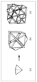
- FIG. 1 is a diagram showing an example of a three-dimensional structure generated from a plurality of polyhedra.
- FIG. 2 is a diagram showing another example of a three-dimensional structure generated from a plurality of polyhedra.
- FIG. 3 is a diagram showing still another example of a three-dimensional structure generated from a plurality of polyhedra.
- FIG. 4 is a diagram showing an example of a crystal structure generated from a three-dimensional structure.
- FIG. 5 is a block diagram showing the overall configuration including the information processing system according to the first embodiment.
- FIG. 6 is a diagram illustrating an example of polyhedral data stored in the first storage unit.
- FIG. 7 is a diagram illustrating an example of second information stored in the second storage unit.
- FIG. 1 is a diagram showing an example of a three-dimensional structure generated from a plurality of polyhedra.
- FIG. 2 is a diagram showing another example of a three-dimensional structure generated from a plurality of polyhedra.
- FIG. 3
- FIG. 8 is a diagram showing an image displayed on the display unit in the first usage example of the first embodiment.
- FIG. 9 is a diagram showing an image displayed on the display unit in the first usage example of the first embodiment.
- FIG. 10 is a diagram showing a list of Bravais lattices.
- FIG. 11 is a diagram showing an image displayed on the display unit in the second usage example of the first embodiment.
- FIG. 12 is a diagram showing an example of the symmetry of a three-dimensional structure.
- FIG. 13 is a diagram showing an image displayed on the display unit in the third usage example of the first embodiment.
- FIG. 14 is a diagram showing an image displayed on the display unit in the fourth usage example of the first embodiment.
- FIG. 15 is a diagram showing an image displayed on the display unit in the fifth usage example of the first embodiment.
- FIG. 16 is a diagram showing an example of skewness of a polyhedron.
- FIG. 17 is a diagram showing an example of a three-dimensional structure with distortion.
- FIG. 18 is a flowchart illustrating an example of the operation of the information processing system according to the first embodiment.
- FIG. 19 is a flowchart showing an example of the process of generating a polyhedron code from a polyhedron.
- FIG. 20 is a diagram showing an example of the process of generating a polyhedral code from a regular tetrahedron.
- FIG. 21 is a diagram showing an example of the process of generating a polyhedron code from a regular octahedron.
- FIG. 22 is a diagram showing an example of the process of generating a polyhedral code from a cuboctahedron.
- FIG. 23 is a flowchart showing an example of the process of generating a multivesicular code from a polyhedral code.
- FIG. 24 is a flowchart showing an example of the process of generating a three-dimensional structure from a multivesicular body code.
- FIG. 25 is a diagram showing a specific example of a multivesicular body code.
- FIG. 26 is a diagram showing a specific example of the process of generating a three-dimensional structure from a multivesicular body code.
- FIG. 27 is a sequence diagram illustrating an operation example of the information processing system, the display unit, the first storage unit, and the second storage unit according to the first embodiment.
- FIG. 28 is a flowchart showing another example of the operation of the information processing system according to the first embodiment.
- FIG. 29 is a diagram showing a specific example of the process of converting a polyhedron into a polyhedron graph.
- FIG. 30 is a diagram showing a specific example of converting a periodic graph into a three-dimensional structure.
- FIG. 31 is a diagram showing an image displayed on the display unit in the first usage example of the second embodiment.
- FIG. 32 is a diagram showing an image displayed on the display unit in the first usage example of the second embodiment.
- FIG. 33 is a diagram showing an image displayed on the display unit in the first usage example of the second embodiment.
- FIG. 34 is a sequence diagram showing a first operation example of the information processing system, the display section, the first storage section, and the second storage section according to the second embodiment.
- FIG. 35 is a diagram showing an image displayed on the display unit in the second usage example of the second embodiment.
- FIG. 36 is a diagram showing an image displayed on the display unit in the second usage example of the second embodiment.
- FIG. 37 is a sequence diagram showing a second operation example of the information processing system, the display section, the first storage section, and the second storage section according to the second embodiment.
- FIG. 38 is a diagram showing sides a, b, and c of surface 1 of a regular tetrahedron.
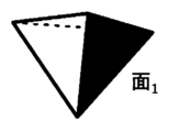
- FIG. 39 is a diagram showing surface 1 of a regular tetrahedron.
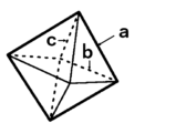
- FIG. 40 is a diagram showing sides a, b, and c of face 1 of a regular octahedron.
- FIG. 41 is a diagram showing surface 2 of a regular octahedron.
- FIG. 42 is a diagram showing face 5 of a regular octahedron.
- FIG. 43 is a diagram showing face 6 of a regular octahedron.
- FIG. 44 is a diagram showing sides a, b, and c of face 1 of a cuboctahedron.
- FIG. 45 is a diagram showing surface 2 of a cuboctahedron.
- FIG. 46 is a diagram showing face 6 of the cuboctahedron.
- FIG. 47 is a diagram showing face 7 of the cuboctahedron.
- a space-dimensional structure is a structure in which a plurality of solids such as polyhedra fill a three-dimensional space without gaps.
- the three-dimensional structure herein refers to a structure in which a plurality of polyhedra are arranged without gaps in a three-dimensional space, and which becomes a crystal structure when atoms are arranged. That is, the three-dimensional structure may be a crystal structure itself, or may be a structure that can express a crystal structure.
- the structure of a material is the microstructure of a material such as a crystalline material or an amorphous material.
- a material such as a crystalline material or an amorphous material.
- an atom exists in coordination with and surrounded by a plurality of adjacent atoms.
- the structure of an inorganic material is made up of polyhedra (coordination polyhedra) formed by connecting the centers of a plurality of adjacent atoms, filling a three-dimensional space without gaps.
- the structure of the inorganic material can be regarded as a three-dimensional structure.
- FIG. 1 is a diagram showing an example of a three-dimensional structure generated from a plurality of polyhedra.
- the three-dimensional structure generated from two regular tetrahedrons and one regular octahedron shown in FIG. 1(a) has a face-centered cubic lattice shown in FIG.
- FIG. 2 is a diagram showing another example of a three-dimensional structure generated from a plurality of polyhedra.
- FIG. 3 is a diagram showing still another example of a three-dimensional structure generated from a plurality of polyhedra.
- a three-dimensional structure generated from one regular octahedron and one cuboctahedron shown in FIG. 3(a) includes a perovskite structure shown in FIG. 3(b).
- one cuboctahedron is shown in FIG. 3(b)
- a plurality of cuboctahedrons are arranged without gaps around the regular octahedron at the center.
- Patent Document 1 discloses a method of generating a three-dimensional spatial figure that allows gaps. However, Patent Document 1 does not disclose a method for generating a three-dimensional structure in which a plurality of polyhedra are arranged without gaps.
- Non-Patent Document 1 discloses a polyhedral code that describes a polyhedron in a number sequence, and a multivesicular body code that describes a multivesicular body in a number sequence. However, Non-Patent Document 1 does not disclose a technique for using these to generate a three-dimensional structure in which a plurality of polyhedra are arranged without gaps.
- an information processing method is an information processing method executed by a computer, which includes the steps of acquiring first information regarding a plurality of polyhedra; and outputting the generated second information, the three-dimensional structure includes the steps of: generating second information regarding a three-dimensional structure in which the plurality of polyhedra are arranged; and outputting the generated second information; It has a structure in which atoms are arranged without gaps, and when the atoms are arranged, it becomes a crystal structure.
- the second information is at least one of information indicating the three-dimensional structure, information indicating a numerical sequence including numbers or letters indicating the three-dimensional structure, and information indicating a periodic graph indicating the three-dimensional structure. It may include one.
- unit structure information indicating the shape of a unit structure in which the plurality of polyhedra are arranged without gaps is acquired as the first information, and the second information is generated.
- the second information indicating the three-dimensional structure in which at least one unit structure indicated by the unit structure information is arranged may be generated.
- the unit structure information may be information indicating a Bravais lattice in the crystal structure.
- symmetry information indicating the symmetry of the three-dimensional structure is acquired as the first information
- the symmetry information indicates the symmetry of the three-dimensional structure.
- Second information regarding the three-dimensional structure having symmetry may be generated.
- the symmetry information may be information indicating a space group in the crystal structure.
- shape information indicating the shape of each of the plurality of polyhedra is acquired as the first information
- shape information indicated by the shape information is The second information regarding the three-dimensional structure in which the plurality of polyhedra are arranged without gaps may be generated.
- step of acquiring the first information number information indicating the number of each shape of the plurality of polyhedra is further acquired as the first information, and in the step of generating the second information, the shape information is The second information regarding the three-dimensional structure may be generated in which the plurality of polyhedra having the indicated shapes are arranged without gaps in the number corresponding to each shape indicated by the number information.
- composition ratio information indicating the composition ratio of each shape of the plurality of polyhedra is further acquired as the first information
- second information regarding the three-dimensional structure may be generated in which the plurality of polyhedra having shapes indicated by the information are arranged without gaps in a composition ratio for each shape indicated by the composition ratio information.
- Second information regarding the three-dimensional structure may be generated by distorting at least a portion of the plurality of polyhedra such that the skewness does not exceed the skewness indicated by the skewness information.
- the skewness may include the position of the center of gravity of the polyhedron, the position of at least one vertex of the polyhedron, the length of at least one side of the polyhedron, and the length of at least one side of the polyhedron, based on the shape of the polyhedron indicated by the shape information.
- the determination may be based on at least one of an angle formed by at least two sides and an area of at least one face of the polyhedron.
- the step of generating the second information includes converting the acquired first information into a plurality of first number sequences representing each of the plurality of polyhedra, and generating the second information using the converted first number sequences. converting the second number sequence representing the multivesicular body into the three-dimensional structure.
- the step of generating the second information includes a step of converting the acquired first information into a plurality of polyhedral graphs representing each of the plurality of polyhedra, and a step of generating the second information using the converted plurality of polyhedron graphs.
- the method may further include converting a periodic graph into the three-dimensional structure.
- material information regarding the composition of the material may be acquired as the first information.
- the material information includes at least one of atoms contained in the material and a composition of the material
- the first information includes the arrangement of the atoms in the three-dimensional structure.
- the second information regarding the three-dimensional structure may be generated based on the arrangement of the atoms indicated by the placement information.
- the three-dimensional structure generated in the step of generating the second information may be the crystal structure that the composition of the material can take.
- an information processing system includes a display unit that displays a first image that receives input of first information regarding a plurality of polyhedra; a display control unit that causes the display unit to display a second image representing second information regarding a three-dimensional structure in which a plurality of polyhedra are arranged, wherein the three-dimensional structure has a plurality of polyhedra arranged without gaps. It has a structure and when the atoms are arranged, it becomes a crystal structure.
- the program according to one aspect of the present disclosure includes the step of acquiring first information regarding a plurality of polyhedra, and generating second information regarding a three-dimensional structure in which the plurality of polyhedra are arranged based on the first information. and outputting the generated second information by a computer, the three-dimensional structure has a structure in which the plurality of polyhedra are arranged without gaps, and atoms are arranged. This is a structure that becomes a crystal structure in some cases.
- the present invention can also be implemented as a computer program that causes a computer to execute the characteristic processing included in the information processing method of the present disclosure. It goes without saying that such a computer program can be distributed via a computer-readable non-transitory recording medium such as a CD-ROM or a communication network such as the Internet.
- the physical properties of a material such as electronic conduction, ionic conduction, or thermal conduction greatly depend on how atoms are coordinated with surrounding atoms, that is, the local coordination environment of atoms.
- a coordination polyhedron For example, in ionic crystalline materials, cations are surrounded by a group of anions. The polyhedron formed by connecting the centers of these anions is called a coordination polyhedron.
- AgI has an fcc type structure with low Ag ion conductivity and a bcc type structure with high Ag ion conductivity.
- I ions around Ag ions are formed by filling tetrahedral and octahedral coordination polyhedra.
- the I ions around the Ag ions are formed by filling a tetrahedral coordination polyhedron, and all sites are equivalent, so the Ag ions are easily conductive.
- the physical properties of the material that is developed vary depending on the type of coordination polyhedron that is filled. Therefore, if a crystal structure can be generated by specifying a highly functional coordination polyhedron, it will be possible to efficiently search for unknown materials. In other words, it is possible to generate a crystal structure that has not been reported so far, and it is possible to discover unknown highly functional materials. Since the structure of an inorganic material can be regarded as a three-dimensional structure, the technology of the present disclosure, which can generate a three-dimensional structure by inputting information on multiple polyhedra, is very effective in searching for unknown materials. .
- the information processing system may be configured such that all the components are included in one computer, or may be configured as a system in which multiple components are respectively distributed among multiple computers. It's okay.
- Inorganic genes include, for example, K.
- CRYSTAL-SELFIES which is an application of SELFIE proposed by Krenn et al., which can express a molecular structure using a string of alphabets, to a three-dimensional structure.
- an inorganic gene is, for example, a multivesicular code that can be converted into a three-dimensional structure.
- the multivesicular body code of type A zeolite (LTA) structure is represented by the numerical sequence "OHG 4 (HG) 4 H”.
- “O”, “H”, and “G” are called a polyhedron code, which is a sequence determined from the input polyhedron.
- “O” means a truncated octahedron, and is represented by the sequence "46 4 (46) 4 4".
- “H” means a cube, and is represented by the numerical sequence "46”.
- G means a truncated cuboctahedron, and is represented by the numerical sequence "6 (48) 3 (64) 6 (84) 3 6".
- this multivesicular body code By changing the arrangement of this multivesicular body code, another three-dimensional structure composed of the same plurality of polyhedra can be generated. Furthermore, by changing the polyhedron code, any polyhedron can be expressed. In this way, by using inorganic genes typified by multivesicular body codes, it becomes possible to comprehensively generate three-dimensional structures from information on multiple polyhedra.
- FIG. 4 is a diagram showing an example of a crystal structure generated from a three-dimensional structure.
- Figure 4(a) represented as "3 4 (3 6 ) 4 (3 4 ) 6 3 4 " in the multivesicular body code
- Figure 4(b) is It is possible to produce crystalline structures.
- a molecular structure can be expressed as a graph. That is, the molecular structure can be expressed as a graph structure in which the "atoms" constituting a compound are “nodes” and the “bonds between atoms" are “edges” connecting the nodes.
- the molecular structure is expressed as a graph and a molecular structure is generated is disclosed in JP-A-2021-081769.
- a periodic graph is also called a crystal net, and is a three-dimensional periodic graph.
- "three-dimensionally periodic” means that three linearly independent translations exist.
- a crystal structure can be converted into a periodic graph by defining the bonds between atoms in the crystal structure.
- a periodic graph can be uniquely converted into a crystal structure.
- a periodic graph with two independent nodes and four edges connecting them as shown in Figure 4(c)
- Figure 4(d) can be interconverted with the diamond-shaped structure shown in Figure 4(d).
- a periodic graph is a graph that has a structure in which a plurality of polyhedra are arranged without gaps, and that can be converted into a three-dimensional structure that becomes a crystal structure when atoms are arranged.
- FIG. 5 is a block diagram showing the overall configuration including the information processing system 100 according to the first embodiment.
- the information processing system 100 is configured as a computer such as a personal computer or a server, for example. That is, the information processing system 100 may be realized by cloud computing, for example.
- Embodiment 1 will be described assuming that information processing system 100 is a stationary computer.
- the information processing system 100 includes an acquisition unit 11, a generation unit 12, and an output unit 13. Further, the information processing system 100 is connected to an input section 2, a display control section 30, a display section 3, a first storage section 4, and a second storage section 5.
- the input unit 2, the display control unit 30, and the display unit 3 are configured by an information terminal used by a user, such as a smartphone, a tablet terminal, or a personal computer.
- the input unit 2, display control unit 30, and display unit 3 may be an input unit, a display control unit, and a display unit included in an information terminal used by a user.
- the input unit 2, the display control unit 30, the first storage unit 4, and the second storage unit 5 may all be connected to the information processing system 100 via a LAN (Local Area Network) or the like, or may be connected to the information processing system 100 via a LAN (Local Area Network) or the like. It may be connected to the information processing system 100 via a network.
- LAN Local Area Network
- the input unit 2, the display control unit 30, the first storage unit 4, and the second storage unit 5 may all be connected to the information processing system 100 via a LAN (Local Area Network) or the like, or may be connected to the information processing system 100 via a LAN (Local Area Network) or the like. It may be connected to the information processing system 100 via a network.
- the input unit 2 is an input interface that accepts user input, and is composed of, for example, a keyboard, a touch sensor, a touch pad, a mouse, or the like.
- the input unit 2 receives an input operation by a user, and outputs a signal corresponding to the input operation to the information processing system 100.
- the display section 3 and the input section 2 are configured independently from each other, but they may be configured integrally like a touch panel.
- the information processing system 100 does not include the display unit 3 and the input unit 2, but may include these.
- the input unit 2 receives input of first information regarding a plurality of polyhedra.
- the first information may include, for example, the type of polyhedron, the number of polyhedra, the allowed skewness, or the allowed symmetry. Details of the first information and input of the first information by the input unit 2 will be described later.
- the display control unit 30 causes the display unit 3 to display images and the like based on information output from the output unit 13 of the information processing system 100.
- the display unit 3 displays images and the like under the control of the display control unit 30.
- the display unit 3 is, for example, a liquid crystal display, a plasma display, an organic EL (Electro-Luminescence) display, or the like, but is not limited thereto.
- the first storage unit 4 is a recording medium for storing a polyhedron database.
- the recording medium is, for example, a hard disk drive, RAM (Random Access Memory), ROM (Read Only Memory), or semiconductor memory. Note that such a recording medium may be volatile or nonvolatile.
- the polyhedron database includes data regarding the polyhedron, such as a diagram of the polyhedron, the number of vertices, the number of sides, the number of faces, or the shape of the face of the polyhedron.
- Examples of polyhedra recorded in the polyhedron database include regular polyhedra such as a regular tetrahedron, a regular hexahedron, a regular octahedron, a regular dodecahedron, and a regular icosahedron.
- Examples of polyhedra include truncated tetrahedron, truncated hexahedron, truncated octahedron, truncated dodecahedron, truncated icosahedron, cuboctahedron, icosico-dodecahedron, and orthorhombic cube.
- the polyhedral data is used when the user inputs first information through the input unit 2.
- FIG. 6 is a diagram showing an example of polyhedron data stored in the first storage unit 4.
- 6(a) shows the structure of a polyhedron (here, a regular octahedron)
- FIG. 6(b) shows the structure of the polyhedron shown in FIG. 6(a) in a predetermined description format (here, a regular octahedron). , xyz file format).
- the first storage unit 4 stores polyhedral data such as an image showing the structure of a polyhedron as shown in FIG. 6(a), and data written in a predetermined description format as shown in FIG. 6(b). Saved as .
- the second storage unit 5 is a recording medium for storing second information regarding the three-dimensional structure generated by the generation unit 12.
- the recording medium is, for example, a hard disk drive, RAM (Random Access Memory), ROM (Read Only Memory), or semiconductor memory. Note that such a recording medium may be volatile or nonvolatile.
- FIG. 7 is a diagram showing an example of the second information stored in the second storage unit 5.
- FIG. 7(a) shows the three-dimensional structure (in this case, an FCC type structure) indicated by the second information
- FIG. 7(b) shows the three-dimensional structure shown in FIG. 7(a). It shows data written in a predetermined description format (here, D-Symbol format).
- the second storage unit 5 stores, for example, an image showing a three-dimensional structure as shown in FIG. 7(a), and data described in a predetermined description format as shown in FIG. 7(b). Saved as information.
- the second information includes, for example, three-dimensional data, graph data, space group, Wyckoff label, cell size, coordinates, maximum distortion of a polyhedron, and the like.
- the file format (extension) of the data saved in the second storage unit 5 is, for example, *. sldprt, *. sldasm, *. iam, *. ipt, *. model, *. CATPart, *. CATProduct, *. 3ds, or *. max etc.
- the file format (extension) please refer to the site indicated by the URL "https://www.data-henkan.com/extension-list”.
- the acquisition unit 11 acquires first information regarding a plurality of polyhedra.
- the acquisition unit 11 is the main body that executes the step of acquiring the first information in the information processing method of the present disclosure. Specifically, the acquisition unit 11 acquires the first information input by the user through the input unit 2. As will be described later, the user performs an operation to input the first information while viewing the first image displayed on the display unit 3 and accepting input of the first information.
- the generation unit 12 generates second information regarding a three-dimensional structure in which a plurality of polyhedra are arranged, based on the first information acquired by the acquisition unit 11.
- the generation unit 12 is the main entity that executes the step of generating the second information in the information processing method of the present disclosure.
- the generation unit 12 performs a process of converting the acquired first information into a plurality of first number sequences each representing a plurality of polyhedra, and a multivesicular body generated using the converted plurality of first number sequences.
- a process of converting the second number sequence representing , into a three-dimensional structure is executed.
- the generation unit 12 converts each of the plurality of polyhedra into polyhedral codes (first number sequence), and converts the multivesicular code (second number sequence) generated using the plurality of polyhedron codes into a three-dimensional structure. Process and execute. Details of each of the above processes will be described later.
- the output unit 13 causes the display unit 3 to display the image etc. by outputting the image etc. to the display control unit 30. Furthermore, the output unit 13 outputs the second information generated by the generation unit 12.
- the output unit 13 is the main body that executes the step of outputting the second information in the information processing method of the present disclosure. Specifically, the output unit 13 outputs the second information by displaying the second image representing the second information generated by the generation unit 12 on the display unit 3. As will be described later, the user performs an operation to select second information to be stored in the second storage unit 5 while viewing the second image displayed on the display unit 3.
- Examples of usage of the information processing system 100 according to the first embodiment will be listed below.
- the information processing system 100 may apply any one of the first to fifth usage examples described below, or may apply a combination of multiple usage examples. Further, in the following description of the second to fifth usage examples, descriptions of points common to the first usage example will be omitted.
- FIG. 8 and 9 are diagrams showing images displayed on the display unit 3 in the first usage example of the first embodiment.
- (a) of FIG. 8 represents an example of the first image displayed on the display unit 3.
- the first image is displayed on the display unit 3 by the output unit 13 by reading the polyhedron data stored in the first storage unit 4.
- the first image includes a shape selection area for selecting the shape of a polyhedron, a unit structure selection area for selecting a unit structure (in this case, a Bravais lattice), and a ⁇ generate three-dimensional structure'' function. '' and an execution icon.
- the shape selection area a plurality of polyhedra that can be selected by the user and a plurality of selection buttons respectively corresponding to the plurality of polyhedra are displayed.
- the shape name of each polyhedron may be displayed in the shape selection area.
- each polyhedron may be displayed as a moving image instead of a still image.
- the user selects a polyhedron to be included in the three-dimensional structure in the shape selection area.
- the acquisition unit 11 (in the step of acquiring the first information) acquires shape information indicating the shape of each of the plurality of polyhedra as the first information.
- the generation unit 12 when the user selects the execution icon, the generation unit 12 (in the step of generating second information) generates second information regarding a three-dimensional structure in which a plurality of polyhedra having the shape indicated by the shape information are arranged without gaps. do.
- the user has selected a regular tetrahedron and a regular octahedron. Therefore, in this case, the generation unit 12 generates second information regarding a three-dimensional structure in which regular tetrahedrons and regular octahedrons are arranged without gaps.
- the unit structure selection area displays the types of unit structures (in this case, Bravais lattice) that can be selected by the user.
- the user can select either "cubic” or “tetragonal”; however, for example, in FIG. It may also be possible to select one from the list of Bravais lattices shown in .
- FIG. 10 is a diagram showing a list of Bravais lattices.
- the user selects a unit structure (here, a Bravais lattice) in the unit structure selection area.
- the acquisition unit 11 acquires, as the first information, unit structure information indicating the shape of the unit structure in which a plurality of polyhedra are arranged without gaps.
- the unit structure information is information indicating a Bravais lattice in a crystal structure.
- the generation unit 12 in the step of generating the second information
- the generation unit 12 generates a three-dimensional structure in which at least one unit structure (in this case, a Bravais lattice) indicated by the unit structure information is arranged. Generate second information regarding.
- FIG. 8(b) shows an example of the second image displayed on the display unit 3.
- the second image is displayed on the display unit 3 after the user selects the execution icon in the first image and the generation unit 12 generates second information regarding the three-dimensional structure.
- the second image includes a table showing a list of three-dimensional structures generated by the generation unit 12 and an execution icon that says "Export selected three-dimensional structure.”
- a column for selecting the 3D structure to be exported a column for displaying the identification number (ID) for each 3D structure, and a number for each shape of multiple polyhedra included in the 3D structure.
- a column indicating the composition ratio (here, the composition ratio) and a column indicating the symmetry of the three-dimensional structure (here, the space group) are displayed.
- the user selects the three-dimensional structure that he or she wants to save and selects the execution icon.
- the display unit 3 displays an image including an area showing the selected three-dimensional structure and an execution icon "Save image”.
- the user checks the selected three-dimensional structure and selects the execution icon if there is no problem.
- the display unit 3 displays an image including a selection area for selecting the storage format of the three-dimensional structure and an execution icon "save".
- the user can select either ".slbprt" or ".slbasm", but even if the user can select other storage formats, good.
- second information regarding the three-dimensional structure selected by the user is stored in the second storage unit 5.
- FIG. 11 is a diagram showing an image displayed on the display unit 3 in the second usage example of the first embodiment.
- FIG. 11 shows an example of the first image displayed on the display section 3.
- the first image includes a symmetry specification area for specifying the symmetry (here, space group) of the three-dimensional structure instead of the unit structure selection area. Contains.
- FIG. 12 is a diagram showing an example of the symmetry of a three-dimensional structure.
- the three-dimensional structure shown in FIG. 12(a) has symmetry shown by the space group "Fm3-m” with the space group number "225".
- the three-dimensional structure shown in FIG. 12(b) has symmetry shown by the space group "l4/mmm” of the space group number "139".
- space groups please refer to the site indicated by the URL "https://en.wikipedia.org/wiki/List_of_space_groups”.
- the user specifies the symmetry of the three-dimensional structure by inputting the number of the desired space group into the text box in the symmetry specification area.
- the range of desired space group numbers may be input in the text box.
- the acquisition unit 11 acquires symmetry information indicating the symmetry of the three-dimensional structure as the first information.
- the symmetry information is information indicating a space group in a crystal structure.
- the generation unit 12 in the step of generating second information
- the generation unit 12 generates second information regarding the three-dimensional structure having the symmetry (here, space group) indicated by the symmetry information. generate.
- a plurality of space groups that can be selected by the user may be listed in the symmetry specification area of the first image instead of a text box. In this case, the user only has to select one of the plurality of space groups.
- FIG. 13 is a diagram showing an image displayed on the display unit 3 in the third usage example of the first embodiment.
- FIG. 13 shows an example of the first image displayed on the display unit 3.
- the first image is a number for specifying the number of multiple polyhedra included in a three-dimensional structure for each shape of the polyhedron. Contains the specified area.
- the name of the shape of the polyhedron selected in the shape selection area and a text box for specifying the number of polyhedra to be included in the three-dimensional structure are displayed.
- the user has selected a regular tetrahedron and a regular octahedron in the shape selection area. Therefore, a text box for specifying the number of regular tetrahedra and a text box for specifying the number of regular octahedrons are displayed in the number specifying area.
- the user specifies the number of polyhedra to be included in the three-dimensional structure by inputting the desired number into the text box in the number specification area.
- the acquisition unit 11 in the step of acquiring the first information further acquires, as the first information, number information indicating the number of each shape of the plurality of polyhedra.
- the generation unit 12 in the step of generating the second information arranges a plurality of polyhedra of the shape indicated by the shape information without gaps for each shape indicated by the number information. second information regarding the three-dimensional structure is generated.
- FIG. 14 is a diagram showing an image displayed on the display unit 3 in the fourth usage example of the first embodiment.
- FIG. 14 shows an example of the first image displayed on the display section 3.
- the first image includes a composition ratio specification area for specifying the composition ratio for each polyhedral shape included in the three-dimensional structure, instead of a unit structure selection area. Contains.
- the composition ratio specification area displays the name of the shape of the polyhedron selected in the shape selection area and a text box for specifying the composition ratio of the polyhedron to be included in the three-dimensional structure.
- the user has selected a regular tetrahedron and a regular octahedron in the shape selection area. Therefore, in the composition ratio designation area, a text box for specifying the composition ratio of the regular tetrahedron and a text box for specifying the composition ratio of the regular octahedron are displayed.
- the user specifies the composition ratio for each shape of the plurality of polyhedra to be included in the three-dimensional structure by inputting the desired composition ratio into the text box in the composition ratio specification area.
- the acquisition unit 11 in the step of acquiring the first information further acquires composition ratio information indicating the composition ratio of each shape of the plurality of polyhedra as the first information.
- the generation unit 12 in the step of generating the second information generates a plurality of polyhedra of the shape indicated by the shape information without any gaps at the composition ratio of each shape indicated by the composition ratio information. Second information regarding the placed three-dimensional structure is generated.
- FIG. 15 is a diagram showing an image displayed on the display unit 3 in the fifth usage example of the first embodiment.
- (a) of FIG. 15 represents an example of the first image displayed on the display unit 3.
- the first image includes a skewness designation area for designating the allowable skewness of the shapes of the plurality of polyhedrons.
- the degree of distortion indicates the degree to which the shape of the polyhedron is distorted based on the shape of the polyhedron indicated by the shape information, that is, the shape of the polyhedron displayed in the shape selection area.
- the skewness is based on the shape of the polyhedron indicated by the shape information, the position of the center of gravity of the polyhedron, the position of at least one vertex of the polyhedron, the length of at least one side of the polyhedron, and the position of at least two sides of the polyhedron. It is determined based on at least one of the angle and the area of at least one face of the polyhedron.
- the generation unit 12 attempts to generate a three-dimensional structure within the range of distortion allowed by the user.
- the skewness is expressed by the following equation (1) using, for example, Baur's method.
- “D” is the skewness
- "l i” is the distance from the center of the polyhedron to the i-th vertex
- " lav " is the average distance from the center of the polyhedron to the vertex.
- Equation (2) the skewness is expressed by the following equation (2) using, for example, Robinson's method (quadratic elongation).
- ⁇ is the skewness
- l i is the distance from the center of the polyhedron to the i-th vertex
- l 0 is the distance from the center to the vertex of a regular polyhedron with the same volume.
- FIG. 16 is a diagram showing an example of the skewness of a polyhedron.
- FIG. 16A shows the shape of a polyhedron (here, a regular tetrahedron) having no distortion when the skewness "D" is "0.0".
- FIG. 16(b) shows a case where the skewness "D" is "0.00869", that is, a polyhedron having distortion (here, the shape of a regular tetrahedron).
- FIG. 17 is a diagram showing an example of a three-dimensional structure with distortion.
- FIG. 17 shows a three-dimensional structure (here, a bcc-type structure) in which a plurality of distorted polyhedra (here, polyhedra obtained by distorting a regular tetrahedron) are arranged without gaps.
- a text box for specifying the allowable skewness of the shapes of multiple polyhedra is displayed.
- the user specifies the allowable skewness of the shapes of the plurality of polyhedra by inputting the desired skewness into the text box in the skewness specification area.
- a desired range of skewness may be input in the text box.
- the acquisition unit 11 in the step of acquiring the first information further acquires skewness information indicating the allowable skewness of the shapes of the plurality of polyhedra as the first information.
- the generation unit 12 distorts at least some of the plurality of polyhedra so as not to exceed the skewness indicated by the skewness information. Generate second information regarding the dimensional structure.
- FIG. 15(b) shows an example of the second image displayed on the display unit 3.
- the second image displays total distortion, which is the sum of distortions of the three-dimensional structures, in a table showing a list of three-dimensional structures generated by the generation unit 12. It further includes a column.
- FIG. 18 is a flowchart illustrating an example of the operation of the information processing system 100 according to the first embodiment.
- Step S101 The acquisition unit 11 acquires first information.
- the first information is input (selected) by the user using the input unit 2 while reading the polyhedron data stored in the first storage unit 4 and viewing the first image displayed on the display unit 3. ), the data is acquired by the acquisition unit 11.
- the first information may be acquired by the acquisition unit 11 by the user inputting original data using the input unit 2 without referring to the first image.
- Step S102 The generation unit 12 executes a process of converting the first information acquired by the acquisition unit 11 into a plurality of first number sequences each representing a plurality of polyhedra.
- the generation unit 12 converts each polyhedron included in the first information into a polyhedron code.
- Step S103 The generation unit 12 executes a process of generating a second number sequence representing a multivesicular body using the plurality of converted first number sequences.
- the generation unit 12 generates a plurality of polyhedral codes based on the plurality of polyhedral codes obtained by the conversion.
- Step S104 The generation unit 12 determines whether the generated multivesicular body code can be converted into a three-dimensional structure.
- the generation unit 12 generates a multivesicular body code based on, for example, whether the faces of two polyhedra that touch each other are the same, or whether a plurality of polyhedra are arranged without gaps (in other words, whether the filling rate is 100% or not). It is possible to determine whether conversion to a three-dimensional structure is possible. If it is determined that conversion is possible (step S104: Yes), the generation unit 12 next executes step S105. If it is determined that conversion is not possible (step S104: No), the generation unit 12 next executes step S106.
- Step S105 The generation unit 12 executes a process of converting the multivesicular body code into a three-dimensional structure.
- K the above-mentioned K.
- the generation unit 12 then executes step S106.
- Step S106 The generation unit 12 determines whether there is a multivesicular body code whose convertibility has not yet been determined. If there is a multivesicular body code that has not been determined yet (S106: Yes), the generation unit 12 returns to step S104. When all the multivesicular body codes are determined (S106: No), the processing of the generation unit 12 is completed. The information processing system 100 (information processing method) then executes step S107.
- Step S107 The output unit 13 executes a process of outputting the second information generated by the generation unit 12.
- the output unit 13 outputs the second information by displaying the second image representing the second information generated by the generation unit 12 on the display unit 3.
- the display section 3 may include a display control section 30.
- the display section 3 including the display control section 30 may be referred to as a display section 3A.
- the output unit 13 may output the second information generated by the generation unit 12 to the display unit 3A. Thereby, the display section 3A may display the second information. That is, the output unit 13 may display the second information on the display unit 3A.
- the generation unit 12 cannot convert all the multivesicular body codes into a three-dimensional structure, the second information is not generated. If the generation unit 12 cannot convert all the multivesicular body codes into a three-dimensional structure, the second information is not displayed on the display unit 3.
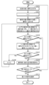
- FIG. 19 is a flowchart showing an example of the process of generating a polyhedron code from a polyhedron.
- Step S201 The generation unit 12 assigns the number "1" to any face of the polyhedron.
- Step S202 The generation unit 12 assigns "1" to the variable "i”.
- Step S203 The generation unit 12 assigns the number "i+1" to the surface adjacent to the "i"-th surface.
- Step S204 The generation unit 12 assigns numbers to the variable "j" number of faces adjacent to the "i” and following faces in a clockwise direction from the "i+1" face to the "i+j" face. The number of surfaces adjacent to the surface "i” or lower is assigned to the variable "j".
- Step S205 The generation unit 12 determines whether numbers have been assigned to all faces of the polyhedron. If all faces of the polyhedron have been numbered (step S205: Yes), the generation unit 12 next executes step S209. If all faces of the polyhedron have not yet been numbered (step S205: No), the generation unit 12 next executes step S206.
- Step S206 The generation unit 12 assigns the number "i+j+1" to an unnumbered surface adjacent to the "i+1" numbered surface.
- Step S207 The generation unit 12 determines whether numbers have been assigned to all faces of the polyhedron. If all faces of the polyhedron have been numbered (step S207: Yes), the generation unit 12 next executes step S209. If all faces of the polyhedron have not yet been numbered (step S207: No), the generation unit 12 next executes step S208.
- Step S208 The generation unit 12 assigns "i+j" to the variable "i”. The generation unit 12 then returns to step S204.
- Step S209 The generation unit 12 converts the number of sides of each face into a numerical sequence by arranging the number of sides of each face in the order of the numbers given to all the faces of the polyhedron.
- Step S210 The generation unit 12 determines whether there are any other sequence patterns. If there are other sequence patterns (step S210: Yes), the generation unit 12 returns to step S201. In this case, in step S201, the generation unit 12 assigns the number "1" to an arbitrary surface different from the surface previously assigned the number "1". If there are no other sequence patterns (step S210: No), the generation unit 12 next executes step S211.
- Step S211 The generation unit 12 selects the smallest number sequence from one or more number sequences.
- the selected number sequence becomes the polyhedral code.
- FIG. 20 is a diagram showing an example of the process of generating a polyhedral code from a regular tetrahedron.
- the generation unit 12 assigns a number "1" to an arbitrary surface.
- the generation unit 12 sequentially assigns numbers "2", “3", and "4" to the faces adjacent to the face "1" clockwise (left-handed).
- the surface numbered “1” is surface 1
- the surface numbered “2” is surface 2
- the surface numbered “3” is surface 3
- the surface numbered "4" is surface 2.
- the surface be surface 4 .
- Surface 1 is the front right surface of each regular tetrahedron shown in FIG. The three sides of surface 1 are named, clockwise, side a, side b, and side c.
- FIG. 38 is a diagram showing sides a, b, and c of surface 1 of a regular tetrahedron.
- FIG. 39 is a diagram showing surface 1 of a regular tetrahedron. In FIG. 39, surface 1 is filled in black.
- Surface 2 shares side a with surface 1
- surface 3 shares side b with surface 1
- surface 4 shares side c with surface 1 .
- the generation unit 12 converts the number of sides of the faces into a numerical sequence in numerical order using terms as terms.
- FIG. 21 is a diagram showing an example of the process of generating a polyhedron code from a regular octahedron.
- the generation unit 12 assigns a number "1" to an arbitrary surface. Then, the generation unit 12 sequentially assigns numbers “2", “3", and “4" to the faces adjacent to the face "1" clockwise (left-handed).
- the generation unit 12 assigns a number "5" to a surface that is adjacent to the surface "2" and has not been assigned a number yet.
- the generation unit 12 sequentially assigns numbers "6" and "7” clockwise (left-handed) from the "5" face to the faces adjacent to the faces assigned numbers "4" and below. do.
- the generation unit 12 assigns the number "8" to a surface adjacent to the surface "5" and to which no number has been assigned yet.
- FIG. 21 the surface numbered “1" is surface 1
- the surface numbered “8" is surface 8
- Surface 1 is the far right surface in each regular octahedron shown in FIG.
- the three sides of surface 1 are named a, b, and c in clockwise order.
- FIG. 40 is a diagram showing sides a, b, and c of face 1 of a regular octahedron.
- Surface 2 shares side a with surface 1
- surface 3 shares side b with surface 1
- surface 4 shares side c with surface 1 .
- FIG. 41 is a diagram showing surface 2 of a regular octahedron. In FIG. 41, surface 2 is filled in black.
- FIG. 40 is a diagram showing sides a, b, and c of face 1 of a regular octahedron.
- surface 2 shares side a with surface 1
- surface 3 shares side b with surface 1
- surface 4 shares side c with surface 1
- FIG. 41 is a
- FIG. 42 is a diagram showing face 5 of a regular octahedron. In FIG. 42, surface 5 is filled in black.
- FIG. 43 is a diagram showing face 6 of a regular octahedron. In FIG. 43, surface 6 is filled in black.
- the generation unit 12 converts the number of sides of the faces into a numerical sequence in numerical order using terms as terms.
- FIG. 22 is a diagram showing an example of the process of generating a polyhedron code from a cuboctahedron.
- the generation unit 12 assigns a number "1" to an arbitrary surface. Then, the generation unit 12 sequentially assigns numbers “2", “3", and “4" to the faces adjacent to the face "1" clockwise (left-handed).
- the generation unit 12 assigns a number "5" to a surface that is adjacent to the surface "2" and has not been assigned a number yet. Then, the generation unit 12 sequentially generates "6", "7", and “8” in clockwise (left-handed) order from the "5" face on the faces adjacent to the faces assigned numbers "4" and below. , “9", and "10".
- the generation unit 12 assigns a number "11” to a surface adjacent to the surface "5" and to which no number has been assigned yet. Then, the generation unit 12 sequentially assigns numbers "12" and “13” clockwise (left-handed) from the "11" face to the faces adjacent to the faces assigned numbers "10" and below. do. Furthermore, the generation unit 12 assigns a number "14" to a surface that is adjacent to the surface "11” and has not been assigned a number yet.
- FIG. 22 the surface numbered “1” is surface 1
- the surface numbered “14” is surface 14
- Surface 1 is a triangular surface on the far right side of each cuboctahedron shown in FIG. The three sides of surface 1 are named a, b, and c in clockwise order.
- FIG. 44 is a diagram showing sides a, b, and c of face 1 of a cuboctahedron.
- Surface 2 shares side a with surface 1
- surface 3 shares side b with surface 1
- surface 4 shares side c with surface 1 .
- FIG. 45 is a diagram showing surface 2 of a cuboctahedron. In FIG. 45, surface 2 is filled in black.
- FIG. 46 is a diagram showing face 6 of the cuboctahedron. In FIG. 46, surface 6 is filled in black.
- FIG. 47 is a diagram showing face 7 of the cuboctahedron. In FIG. 47, surface 7 is filled in black.
- the generation unit 12 converts the number of sides of the faces into a numerical sequence in numerical order using terms as terms.
- the term corresponding to the surface is "3".
- sequence A is less than sequence B.
- sequence B is less than sequence B.
- FIG. 23 is a flowchart showing an example of the process of generating a multivesicular code from a polyhedral code.
- the acquisition unit 11 will be described as acquiring the shapes of each of the plurality of polyhedra and the number of each shape as the first information.
- Step S301 The generation unit 12 acquires the shape of each of the plurality of polyhedra and the number of each shape from among the first information acquired by the acquisition unit 11.
- Step S302 The generation unit 12 prepares a plurality of polyhedral codes by converting each of the plurality of polyhedrons into a polyhedral code.
- Step S303 The generation unit 12 generates a plurality of polyhedral codes based on the plurality of polyhedral codes.
- the generation unit 12 generates a plurality of polyhedral codes by rearranging the sequence "OOOOOTTTTTT" of the plurality of polyhedral codes.
- a plurality of polyhedral codes are generated based on a plurality of polyhedral codes, that is, eight T's and four O's.
- Each of the plurality of multivesicular cords includes eight T's and four O's.
- "OOOOOTTTTTTTT” and “TOOOOTTTTTT” are different multivesicular body codes.
- FIG. 24 is a flowchart showing an example of the process of generating a three-dimensional structure from a multivesicular body code.
- Step S401 The generation unit 12 generates a polyhedron corresponding to each term of the polyhedral code, that is, the polyhedral code.
- Step S402 The generation unit 12 assigns numbers to each face of the polyhedron clockwise in the order of the terms of the multivesicular body code. For example, if the polyhedra corresponding to the first term of the multivesicular code are assigned numbers "1" to "4", the polyhedra corresponding to the second term of the multivesicular code are assigned numbers starting from "5". be done. That is, the generation unit 12 assigns numbers to each face of each polyhedron so that the numbers do not overlap in each polyhedron.
- Step S403 The generation unit 12 determines the polyhedron having the lowest number of uncombined faces as a partial polyhedron.
- Step S404 The generation unit 12 selects the faces of the remaining polyhedrons having the same shape as the face with the smallest number of the partial polyhedron. For example, if the smallest numbered face of a partial polyhedron has a triangular shape, the same triangular faces are selected from the remaining polyhedra.
- one surface may be selected, or multiple surfaces may be selected.
- Step S405 The generation unit 12 combines the lowest numbered surface of the selected surfaces with the uncombined lowest numbered surface of the partial multivesicular body.
- Step S406 The generation unit 12 determines whether there is a set of unconnected faces between the faces of the partial multivesicular body and the faces of the remaining selected polyhedra. If there is a set of uncombined surfaces (step S406: Yes), the generation unit 12 next executes step S407. If there is no set of uncombined surfaces (step S406: No), the generation unit 12 next executes step S408.
- Step S407 The generation unit 12 combines the uncombined faces of the partial polyhedron and the remaining selected polyhedra. The generation unit 12 then returns to step S406.
- Step S408 The generation unit 12 determines whether there are any remaining uncombined polyhedra. If there are remaining uncombined polyhedra (step S408: Yes), the generation unit 12 returns to step S403. If there are no uncombined remaining polyhedra (step S408: No), the generation unit 12 next executes step S409.
- Step S409 The generation unit 12 determines whether all polyhedra are filled 100%, in other words, whether all polyhedra are arranged without gaps. If all polyhedra have been filled 100% (step S409: Yes), the processing of the generation unit 12 is completed. In this case, the generation unit 12 has converted the multivesicular body code into a three-dimensional structure. If all polyhedra are not filled 100% (step S409: No), the generation unit 12 next executes step S410.
- Step S410 The generation unit 12 discards three-dimensional structures whose filling rate is not 100%, and completes the process. In this case, the generation unit 12 does not convert the multivesicular body code into a three-dimensional structure.
- FIG. 25 is a diagram showing a specific example of a multivesicular body code.
- FIG. 26 is a diagram showing a specific example of the process of generating a three-dimensional structure from a multivesicular body code. As shown in FIG. 25, a case will be described below in which the multivesicular body code "TOOOOTTTTTT" is converted into a three-dimensional structure.
- the generation unit 12 converts the polyhedral codes "T” and "O" in the multivesicular code into corresponding polyhedrons.
- the polyhedron code "T” is a regular tetrahedron
- the polyhedron code “O” is a regular octahedron.
- the generation unit 12 assigns numbers to each face of the polyhedron clockwise in the order of the plurality of terms included in the multivesicular body code.
- each face of the regular tetrahedron corresponding to the first term (leftmost term) of the multivesicular body code is given a number from ⁇ 1'' to ⁇ 4'', and each face of the regular octahedron corresponding to the second term is assigned a number from ⁇ 1'' to ⁇ 4''.
- the faces are numbered from "5" to "10".
- the generation unit 12 determines the regular tetrahedron corresponding to the first term of the multivesicular body code as a partial multivesicular body.
- the generation unit 12 selects the remaining polyhedral faces having the shape of the smallest numbered face of the regular tetrahedron that is the partial multivesicular body.
- the shape of the face "1" which is the lowest numbered face of the partial multivesicle, is triangular, and the shapes of the faces of all remaining polyhedra are triangular, so the faces of all remaining polyhedra are selected.
- the generation unit 12 combines the lowest numbered surface of the selected surfaces with the uncombined lowest numbered surface of the partial multivesicular body.
- the "1" face of the regular tetrahedron, which is a partial multivesicular body, and the "5" face of the regular octahedron, which corresponds to the second term of the multivesicular body code are combined.
- the generation unit 12 repeats the process of joining the uncombined faces.
- the generation unit 12 combines the face with the lowest unbound number "2" of the partial multivesicular body and the face with the lowest unbound number "13" among the remaining selected polyhedra. .
- the generation unit 12 combines the face "3" and the face "21", and the face "4" and the face "29".
- the generation unit 12 since there are remaining uncombined polyhedra, the generation unit 12 generates a polyhedron (here, a polyhedron corresponding to the second term of the multivesicular body code) having the lowest unconnected face number among the remaining polyhedra.
- a regular octahedron is determined as a new partial multivesicular body, and the same process as above is repeated.
- the generation unit 12 generates a three-dimensional structure with a filling rate of 100% by repeating the above process until there are no remaining unbonded polyhedra.
- the generation unit 12 combines the face with the lowest unbound number "6" of the new partial multivesicular body with the face with the lowest unbound number "37” among the remaining selected polyhedra. .
- the generation unit 12 combines the faces "7" and "41", the faces “8” and “45”, and the faces "9” and "49”. , join the faces "10” and "53”, join the faces "11” and "57”, and join the faces "12” and "59”.
- the multivesicular body code "TOOOTTTTTTTTTT the three-dimensional structure generated by the generation unit 12 is an fcc type structure.
- FIG. 27 is a sequence diagram showing an example of the operation of the information processing system 100, the display section 3, the first storage section 4, and the second storage section 5 according to the first embodiment.
- Step S501 The acquisition unit 11 of the information processing system 100 acquires first information.
- the first information is input (selected) by the user using the input unit 2 while reading the polyhedral data stored in the first storage unit 4 and viewing the first image displayed on the display unit 3.
- the information is acquired by the acquisition unit 11.
- Step S502 The generation unit 12 of the information processing system 100 executes a process of converting each polyhedron included in the first information acquired by the acquisition unit 11 into a polyhedron code.
- Step S503 The generation unit 12 of the information processing system 100 executes a process of generating a plurality of polyhedral codes based on the plurality of polyhedral codes obtained by the conversion.
- Step S504 The generation unit 12 of the information processing system 100 executes a process of determining whether the generated multivesicular body code can be converted into a three-dimensional structure.
- Step S505 The generation unit 12 of the information processing system 100 executes a process of converting the multivesicular body code determined to be convertible into a three-dimensional structure.
- Step S506 The display unit 3 displays a second image representing second information output from the output unit 13 of the information processing system 100.
- Step S507 When the user selects a three-dimensional structure to save while viewing the second image displayed on the display unit 3, the information processing system 100 provides second information regarding the selected three-dimensional structure to the second storage unit 5. Thereby, the second storage unit 5 stores second information regarding the three-dimensional structure selected by the user.
- a three-dimensional structure formed by combining the input multiple polyhedra that is, a space-filling structure in a three-dimensional space
- a polyhedron is converted into a polyhedral code
- a multivesicular body code is generated from the converted polyhedral code
- the generated other body code is converted into a three-dimensional structure.
- the information processing system 100 according to the first embodiment may convert a polyhedron into a polyhedral graph, generate a periodic graph from the converted polyhedron graph, and convert the generated periodic graph into a three-dimensional structure.
- the generation unit 12 (the step of generating second information) converts the acquired first information into a plurality of polyhedron graphs each representing a plurality of polyhedra, and generates the second information using the converted polyhedron graphs.
- a process of converting a periodic graph into a three-dimensional structure may also be executed.
- FIG. 28 is a flowchart showing another example of the operation of the information processing system 100 according to the first embodiment.
- Step S108 The acquisition unit 11 acquires first information.
- the first information is input (selected) by the user using the input unit 2 while reading the polyhedron data stored in the first storage unit 4 and viewing the first image displayed on the display unit 3. ), the data is acquired by the acquisition unit 11.
- the first information may be acquired by the acquisition unit 11 by the user inputting original data using the input unit 2 without referring to the first image.
- Step S109 The generation unit 12 determines the position of the vertex of each polyhedron (vertex site) and the position of the center of each polyhedron (center site) based on the acquired first information.
- Step S110 The generation unit 12 executes a process of converting the first information acquired by the acquisition unit 11 into a plurality of polyhedron graphs each representing a plurality of polyhedra.
- the generation unit 12 converts each polyhedron included in the first information into a polyhedron graph.
- Step S111 The generation unit 12 executes a process of generating a periodic graph using the converted polyhedral graph.
- the generation unit 12 generates a plurality of periodic graphs based on a combination of a plurality of polyhedral graphs obtained by the conversion.
- Step S112 The generation unit 12 determines whether the generated periodic graph can be converted into a three-dimensional structure. For example, the generation unit 12 determines whether or not the faces of two polyhedra that touch each other are the same, and whether or not the plurality of polyhedra are arranged without gaps (in other words, whether the filling rate is 100% or not). It is possible to determine whether conversion to a dimensional structure is possible. If it is determined that conversion is possible (step S112: Yes), the generation unit 12 next executes step S113. If it is determined that conversion is not possible (step S112: No), the generation unit 12 next executes step S114.
- Step S113 The generation unit 12 executes a process of converting a periodic graph into a three-dimensional structure.
- the conversion process for example, the method shown in the above-mentioned Kotani-Sunada theory (Kotani-Sunada, 2000, Trans. Amer. Mat) can be used.
- the generation unit 12 then executes step S114.
- Step S114 The generation unit 12 determines whether there is a periodic graph whose convertibility has not yet been determined. If there is a periodic graph that has not been determined yet (S114: Yes), the generation unit 12 returns to step S112. If the determination is made for all periodic graphs (S114: No), the processing of the generation unit 12 is completed. The information processing system 100 (information processing method) then executes step S115.
- Step S115 The output unit 13 executes a process of outputting the second information generated by the generation unit 12.
- the output unit 13 outputs the second information by displaying the second image representing the second information generated by the generation unit 12 on the display unit 3.
- the display section 3 may include a display control section 30.
- the display section 3 including the display control section 30 may be referred to as a display section 3A.
- the output unit 13 may output the second information generated by the generation unit 12 to the display unit 3A. Thereby, the display section 3A may display the second information. That is, the output unit 13 may display the second information on the display unit 3A.
- FIG. 29 is a diagram showing a specific example of the process of converting a polyhedron into a polyhedron graph.
- FIG. 30 is a diagram showing a specific example of converting a periodic graph into a three-dimensional structure.
- the generation unit 12 determines each vertex site of the polyhedron and the center site of the polyhedron. In the case of the regular tetrahedron shown in FIG. 29(a), the generation unit 12 determines four vertex sites and one center site as shown in FIG. 29(b). Furthermore, in the case of the regular octahedron shown in FIG. 29(d), the generation unit 12 determines six vertex sites and one vertex site, as shown in FIG. 29(e).
- the generation unit 12 generates a polyhedron graph by connecting each vertex site and the center site of the polyhedron.
- the generation unit 12 When the polyhedron is a regular tetrahedron, the generation unit 12 generates a polyhedron graph in which edges extend from the center node to each of the four vertex nodes, as shown in FIG. 29(c). Further, when the polyhedron is a regular octahedron, the generation unit 12 generates a polyhedron graph in which edges extend from the center node to each of the six vertex nodes, as shown in FIG. 29(f).
- the generation unit 12 generates a periodic graph by connecting each vertex node in the generated polyhedral graph.
- the periodic graph shown in FIG. 30(a) is a periodic graph generated from two polyhedral graphs corresponding to two regular tetrahedra and one polyhedral graph corresponding to one regular octahedron. This periodic graph is generated by combining the vertex nodes of each polyhedral graph into one.
- the generation unit 12 then converts the generated periodic graph into a three-dimensional structure.
- the three-dimensional structure (fcc type structure) shown in FIG. 30(b) is generated by converting the periodic graph shown in FIG. 30(a).
- the information processing system 200 according to the second embodiment is different from the information processing system 100 according to the first embodiment in that the acquisition unit 11 acquires material information regarding the composition of the material as the first information.
- the information processing system 200 according to the second embodiment includes an acquisition section 11, a generation section 12, and an output section 13, and has a configuration similar to the information processing system 100 according to the first embodiment. Since these are common, their explanation will be omitted.
- 31, 32, and 33 are diagrams showing images displayed on the display section 3 in the first usage example of the second embodiment.
- 31(a) and 31(b) each represent an example of the first image initially displayed on the display unit 3.
- the display unit 3 may display the first image shown in FIG. 31(a), or may display the first image shown in FIG. 31(b).
- the first image shown in FIG. 31(a) includes an element selection area for selecting an element and an execution icon "Next".
- a periodic table is displayed in the element selection area.
- the user selects an element (atom) contained in a desired material in the element selection area.
- the element becomes the element arranged at the center of the polyhedron.
- the acquisition unit 11 acquires material information regarding the composition of the material (here, atoms contained in the material) as the first information. It turns out.
- the first image shown in FIG. 31(b) includes a composition specification area for specifying the composition of the material and an execution icon labeled "Next."
- a text box is displayed for the user to specify the desired composition of the material.
- the user enters the chemical formula of the desired material into the text box.
- the acquisition unit 11 acquires material information regarding the composition of the material (here, the composition of the material itself) as the first information.
- expressions using subscripts are omitted.
- FIG. 32 shows an example of the first image displayed second on the display unit 3.
- the first image shown in FIG. 32 is displayed on the display unit 3 when the user selects the execution icon in the first image shown in FIG. 31(a) or the first image shown in FIG. 31(b). be done.
- an arrangement designation area for specifying the arrangement of elements (atoms) included in the material and an execution icon "Next" are displayed.
- a table showing the number of each element in the polyhedron and the position (vertex or center) of each element in the polyhedron is displayed.
- the acquisition unit 11 acquires, as the first information, arrangement information regarding the arrangement of elements (atoms) in the three-dimensional structure.
- the acquisition unit 11 acquires, as the first information, placement information regarding the placement of elements (atoms) in the three-dimensional structure.
- FIG. 33 shows an example of the first image displayed third on the display unit 3.
- the first image shown in FIG. 33 is displayed on the display unit 3 when the user selects the execution icon in the first image shown in FIG. 32.
- the first image shown in FIG. 33 includes a combination selection area for selecting a combination of polyhedra, a skewness designation area, and an execution icon "generate three-dimensional structure".
- the first image shown in FIG. 33 may include, for example, a unit structure selection area instead of the skewness specification area. That is, any one of the first to fifth usage examples of the first embodiment, or a combination thereof, may be applied to the first image shown in FIG. 33, except for the combination selection area.
- the combination selection area displays combinations of a plurality of polyhedra that can be selected by the user based on the arrangement information, and a plurality of selection buttons that respectively correspond to the combinations of the plurality of polyhedra.
- the name of the shape of each polyhedron may be displayed in the combination selection area.
- each polyhedron may be displayed as a moving image instead of a still image.
- the user selects a combination of polyhedra to be included in the three-dimensional structure in the combination selection area.
- the acquisition unit 11 acquires, as the first information, shape information indicating the shape of each of the plurality of polyhedra and composition ratio information indicating the composition ratio of each shape. I will do it.
- the generation unit 12 determines number information indicating the number of each shape of a plurality of polyhedra based on the composition ratio information.
- n may be a natural number of 2 or more and a predetermined value. The following process may be performed for each of the plural pieces of number information.
- the generation unit 12 (in the step of generating the second information) generates second information regarding a three-dimensional structure in which a number of polyhedra having the shape indicated by the shape information are arranged without gaps in a number corresponding to the polyhedra.
- the generation unit 12 generates second information regarding a three-dimensional structure in which a plurality of polyhedra having the shape indicated by the shape information are arranged without any gaps in the composition ratio of each shape indicated by the composition ratio information.
- the above shape information and composition ratio information are information based on arrangement information. Therefore, it can be said that the generation unit 12 (in the step of generating the second information) generates the second information regarding the three-dimensional structure based on the arrangement of elements (atoms) indicated by the arrangement information.
- the second image is displayed on the display unit 3, similar to the first usage example of the first embodiment. Then, by selecting the three-dimensional structure that the user wants to save and the storage format of the three-dimensional structure, second information regarding the three-dimensional structure selected by the user is saved in the second storage unit 5.
- FIG. 34 is a sequence diagram showing a first operation example of the information processing system 200, the display section 3, the first storage section 4, and the second storage section 5 according to the second embodiment.
- Step S601 The acquisition unit 11 of the information processing system 200 acquires material information and arrangement information.
- the material information is acquired by the acquisition unit 11 by the user inputting (selecting) using the input unit 2 while looking at the first image (see FIG. 31) that is first displayed on the display unit 3.
- the arrangement information is acquired by the acquisition unit 11 by the user inputting (selecting) using the input unit 2 while looking at the first image displayed second on the display unit 3 (see FIG. 32). Ru.
- Step S602 The acquisition unit 11 of the information processing system 200 searches for combinations of a plurality of polyhedra that can be selected by the user based on the arrangement information.
- the acquisition unit 11 reads and refers to the polyhedron data stored in the first storage unit 4.
- Step S603 The display unit 3 displays combinations of multiple polyhedra output from the output unit 13 of the information processing system 200. In other words, the display unit 3 displays the first image including a combination selection area for selecting a combination of polyhedra.
- Step S604 The acquisition unit 11 of the information processing system 200 acquires first information.
- the first information is shape information and composition ratio information, which the user inputs ( selection), the acquisition unit 11 acquires the information.
- Step S605 The generation unit 12 of the information processing system 200 executes a process of converting the multivesicular code determined to be convertible into a three-dimensional structure. Note that step S605 is the same process as step S505 (see FIG. 27). Furthermore, between step S604 and step S605, the same processing as steps S502 to S504 (see FIG. 27) is executed.
- Step S606 The display unit 3 displays a second image representing second information output from the output unit 13 of the information processing system 200.
- Step S607 When the user selects a three-dimensional structure to be saved while viewing the second image displayed on the display unit 3, the information processing system 200 provides second information regarding the selected three-dimensional structure to the second storage unit 5. Thereby, the second storage unit 5 stores second information regarding the three-dimensional structure selected by the user.
- FIG. 35 and 36 are both diagrams showing images displayed on the display unit 3 in the second usage example of the second embodiment.
- FIG. 35 shows an example of the first image that is displayed second on the display unit 3.
- the first image shown in FIG. 35 is displayed on the display unit 3 instead of the first image shown in FIG. 32.
- the first image shown in FIG. 35 differs from the first image shown in FIG. It includes an execution icon that says "No" for not inputting information.
- the display unit 3 displays, for example, one of the first to fifth usage examples of the first embodiment, A combined first image (see (a) of FIG. 8, FIG. 11, FIG. 13, FIG. 14, and (a) of FIG. 15) that prompts input of polyhedron information is displayed. Therefore, when the user inputs (selects) polyhedron information while looking at the first image displayed on the display unit 3, the acquisition unit 11 (in the step of acquiring the first information) obtains the polyhedron information (first information). will be obtained.
- the generation unit 12 (in the step of generating second information) generates second information regarding the crystal structure that the composition of the material as a three-dimensional structure can have.
- the generation unit 12 generates the second information based not only on the material information and placement information but also on the polyhedron information.
- the generation unit 12 will generate the second information based on the material information and placement information.
- FIG. 36 shows an example of the second image displayed on the display section 3.
- the second image is displayed on the display unit 3 after the generation unit 12 generates second information regarding the three-dimensional structure (here, the crystal structure).
- the second image includes a list of crystal structures generated by the generation unit 12 and an execution icon that says "Export selected crystal structure.”
- the user selects the crystal structure that he or she wants to save and selects the execution icon. Thereafter, as in the first embodiment, the user selects a desired storage format, and the second information regarding the crystal structure selected by the user is stored in the second storage unit 5.
- FIG. 37 is a sequence diagram showing a second operation example of the information processing system 200, the display section 3, the first storage section 4, and the second storage section 5 according to the second embodiment.
- explanation will be given assuming that the user inputs polyhedron information.
- Step S701 The acquisition unit 11 of the information processing system 200 acquires material information and arrangement information.
- the material information is acquired by the acquisition unit 11 by the user inputting (selecting) using the input unit 2 while looking at the first image (see FIG. 31) that is first displayed on the display unit 3.
- the arrangement information is acquired by the acquisition unit 11 by the user inputting (selecting) using the input unit 2 while looking at the first image displayed second on the display unit 3 (see FIG. 32). Ru.
- Step S702 The acquisition unit 11 of the information processing system 200 acquires first information.
- the first information is polyhedron information, and is acquired by the acquisition unit 11 by the user inputting (selecting) using the input unit 2 while viewing the first image displayed on the display unit 3. Ru.
- Step S703 The generation unit 12 of the information processing system 200 executes a process of converting the multivesicular code determined to be convertible into a three-dimensional structure. Note that step S703 is the same process as step S505 (see FIG. 27). Furthermore, between step S702 and step S703, the same processing as steps S502 to S504 (see FIG. 27) is executed.
- the generation unit 12 of the information processing system 200 generates a plurality of placement pattern candidates for each generated three-dimensional structure.
- the arrangement pattern candidates are candidates for patterns of elements (atoms) arranged at each vertex and center of each polyhedron included in the three-dimensional structure. Note that the arrangement pattern candidates may also include a pattern in which no element is arranged at the center of the polyhedron.
- Step S705 The generation unit 12 of the information processing system 200 generates a crystal structure for each arrangement pattern candidate. Specifically, the generation unit 12 generates a crystal structure by arranging elements (atoms) at each vertex and center of each polyhedron according to the arrangement pattern candidate.
- Step S706 The display unit 3 displays a second image representing second information regarding the crystal structure, which is output from the output unit 13 of the information processing system 200.
- Step S707 When the user selects a crystal structure to be saved while viewing the second image displayed on the display unit 3, the information processing system 200 provides second information regarding the selected crystal structure to the second storage unit 5. Thereby, the second storage unit 5 stores second information regarding the crystal structure selected by the user.
- a three-dimensional structure that is, a space-filling structure in a three-dimensional space formed by combining a plurality of polyhedra based on the input material information is created.
- a three-dimensional structure that is, a space-filling structure in a three-dimensional space
- the second information is information indicating the three-dimensional structure itself, but is not limited to this.
- the second information includes at least one of information indicating a three-dimensional structure, information indicating a numerical sequence (e.g., multivesicular body code) expressing the three-dimensional structure, and information indicating a periodic graph expressing the three-dimensional structure. It's fine as long as you are.
- the information processing systems 100 and 200 display the first image or the second image on the display unit 3, but the present invention is not limited to this.
- the information processing systems 100 and 200 may output information included in the first image or the second image without displaying the first image or the second image themselves on the display unit 3.
- the acquisition unit 11 of the information processing system 100, 200 acquires the first information input by the user through the input unit 2, but the invention is not limited to this.
- the acquisition unit 11 may acquire the first information by reading information stored in the first storage unit 4 without receiving input from the user.
- the first storage section 4 and the second storage section 5 are realized by mutually different recording media, but the invention is not limited to this.
- the first storage unit 4 and the second storage unit 5 may be realized by the same recording medium.
- each of the information processing systems 100 and 200 is configured with the acquisition unit 11, the generation unit 12, and the output unit 13, but the invention is not limited to this.
- the information processing system 100 may include a display control section 30 and a display section 3, as indicated by "100A" in FIG.
- the information processing system 200 may include a display control section 30 and a display section 3.
- each component may be configured with dedicated hardware, or may be realized by executing a software program suitable for each component.
- Each component may be realized by a program execution unit such as a CPU (Central Processing Unit) or a processor reading and executing a software program recorded on a recording medium such as a hard disk or a semiconductor memory.
- a program execution unit such as a CPU (Central Processing Unit) or a processor reading and executing a software program recorded on a recording medium such as a hard disk or a semiconductor memory.
- At least one of the above devices is specifically a computer system consisting of a microprocessor, ROM (Read Only Memory), RAM (Random Access Memory), hard disk unit, display unit, keyboard, mouse, etc. be.
- a computer program is stored in the RAM or hard disk unit.
- the at least one device described above achieves its functions by the microprocessor operating according to a computer program.
- a computer program is configured by combining a plurality of instruction codes indicating instructions to a computer in order to achieve a predetermined function.
- a part or all of the components constituting at least one of the above devices may be composed of one system LSI (Large Scale Integration).
- a system LSI is a super-multifunctional LSI manufactured by integrating multiple components on a single chip, and specifically, it is a computer system that includes a microprocessor, ROM, RAM, etc. .
- a computer program is stored in the RAM. The system LSI achieves its functions by the microprocessor operating according to a computer program.
- An IC card or module is a computer system consisting of a microprocessor, ROM, RAM, etc.
- the IC card or module may include the above-mentioned super multifunctional LSI.
- An IC card or module achieves its functions by a microprocessor operating according to a computer program. This IC card or this module may be tamper resistant.
- the present disclosure may be the method described above. Furthermore, it may be a computer program that implements these methods using a computer, or it may be a digital signal formed from a computer program.
- the present disclosure describes how to store a computer program or a digital signal on a computer-readable recording medium, such as a flexible disk, a hard disk, a CD (Compact Disc)-ROM, a DVD, a DVD-ROM, a DVD-RAM, and a BD (Blu-ray).
- a computer-readable recording medium such as a flexible disk, a hard disk, a CD (Compact Disc)-ROM, a DVD, a DVD-ROM, a DVD-RAM, and a BD (Blu-ray).
- the information may be recorded on a registered trademark Disc), a semiconductor memory, or the like. Further, it may be a digital signal recorded on these recording media.
- the present disclosure may transmit a computer program or a digital signal via a telecommunication line, a wireless or wired communication line, a network typified by the Internet, data broadcasting, or the like.
- program or digital signal may be implemented by another independent computer system by recording the program or digital signal on a recording medium and transferring it, or by transferring the program or digital signal via a network or the like.
- an n-th number corresponding to the n-th polyhedron; a plurality of first polyhedra, ⁇ , the n-th polyhedron and one or more corresponding n-th polyhedra of the n-th number are determined;
- a plurality of codes including one or more first codes to one or more n-th codes are rearranged, thereby determining a plurality of multivesicular body codes (for example, see FIG. 23),
- the first code corresponds to the first code for the first number and the first polyhedron, and the one or more n-th codes correspond to the n-th code for the n-th number and the n-th polyhedron.
- the first code is determined based on the number of sides of each of the faces included in the first polyhedron
- the n-th code is determined based on the number of sides of each of the faces included in the n-th polyhedron. Determined based on the number of multiple sides (see, for example, FIGS. 20, 21, and 22)
- a three-dimensional structure including the one or more first polyhedrons to the one or more n-th polyhedrons is determined (for example, see FIG. 24).
- the three-dimensional structure does not include one or more polyhedra other than the one or more first polyhedrons, ⁇ , the one or more n-th polyhedrons,
- the two polyhedra arbitrarily selected from the one or more first polyhedrons to the one or more n-th polyhedrons do not overlap,
- the multiple positions included in the three-dimensional structure correspond to the multiple positions of multiple atoms included in the crystal structure.
- the present disclosure is useful when searching for unknown materials.
Landscapes
- Engineering & Computer Science (AREA)
- Theoretical Computer Science (AREA)
- Computing Systems (AREA)
- Bioinformatics & Computational Biology (AREA)
- Life Sciences & Earth Sciences (AREA)
- Bioinformatics & Cheminformatics (AREA)
- Chemical & Material Sciences (AREA)
- Crystallography & Structural Chemistry (AREA)
- Physics & Mathematics (AREA)
- General Physics & Mathematics (AREA)
- General Engineering & Computer Science (AREA)
- Computer Graphics (AREA)
- Software Systems (AREA)
- Computer Hardware Design (AREA)
- Architecture (AREA)
- Human Computer Interaction (AREA)
- Data Mining & Analysis (AREA)
- Spectroscopy & Molecular Physics (AREA)
- Analytical Chemistry (AREA)
- Chemical Kinetics & Catalysis (AREA)
- Processing Or Creating Images (AREA)
- Geometry (AREA)
Priority Applications (4)
| Application Number | Priority Date | Filing Date | Title |
|---|---|---|---|
| CN202380029388.5A CN118974837A (zh) | 2022-03-31 | 2023-01-23 | 信息处理方法、信息处理系统以及程序 |
| JP2024511290A JPWO2023188731A1 (https=) | 2022-03-31 | 2023-01-23 | |
| EP23778770.0A EP4503044A4 (en) | 2022-03-31 | 2023-01-23 | INFORMATION PROCESSING METHOD, INFORMATION PROCESSING SYSTEM AND PROGRAM |
| US18/888,234 US20250014273A1 (en) | 2022-03-31 | 2024-09-18 | Information processing method, information processing system, and recording medium |
Applications Claiming Priority (2)
| Application Number | Priority Date | Filing Date | Title |
|---|---|---|---|
| JP2022-057910 | 2022-03-31 | ||
| JP2022057910 | 2022-03-31 |
Related Child Applications (1)
| Application Number | Title | Priority Date | Filing Date |
|---|---|---|---|
| US18/888,234 Continuation US20250014273A1 (en) | 2022-03-31 | 2024-09-18 | Information processing method, information processing system, and recording medium |
Publications (1)
| Publication Number | Publication Date |
|---|---|
| WO2023188731A1 true WO2023188731A1 (ja) | 2023-10-05 |
Family
ID=88200771
Family Applications (1)
| Application Number | Title | Priority Date | Filing Date |
|---|---|---|---|
| PCT/JP2023/001943 Ceased WO2023188731A1 (ja) | 2022-03-31 | 2023-01-23 | 情報処理方法、情報処理システム、及びプログラム |
Country Status (5)
| Country | Link |
|---|---|
| US (1) | US20250014273A1 (https=) |
| EP (1) | EP4503044A4 (https=) |
| JP (1) | JPWO2023188731A1 (https=) |
| CN (1) | CN118974837A (https=) |
| WO (1) | WO2023188731A1 (https=) |
Citations (2)
| Publication number | Priority date | Publication date | Assignee | Title |
|---|---|---|---|---|
| JP2020106483A (ja) * | 2018-12-28 | 2020-07-09 | 日本製鉄株式会社 | モデル作成装置、モデル作成方法およびプログラム |
| JP2021081769A (ja) | 2019-11-14 | 2021-05-27 | 株式会社 ディー・エヌ・エー | 化合物の構造を自動生成するための化合物構造自動生成装置、化合物構造自動生成プログラム及び化合物構造自動生成方法 |
Family Cites Families (15)
| Publication number | Priority date | Publication date | Assignee | Title |
|---|---|---|---|---|
| US5448687A (en) * | 1988-09-13 | 1995-09-05 | Computer Design, Inc. | Computer-assisted design system for flattening a three-dimensional surface and for wrapping a flat shape to a three-dimensional surface |
| US5553206A (en) * | 1993-02-12 | 1996-09-03 | International Business Machines Corporation | Method and system for producing mesh representations of objects |
| DE69725249D1 (de) * | 1996-02-20 | 2003-11-06 | Sega Enterprises Kk | Gerät, verfahren und aufzeichnungsmedium zur bilderzeugung |
| JP5267902B2 (ja) * | 2007-08-10 | 2013-08-21 | 学校法人関西学院 | 多面体結晶構造模型 |
| JP2010198684A (ja) * | 2009-02-25 | 2010-09-09 | Seiko Epson Corp | 電子機器の交換ユニット毎に集約した寿命予測値の表示方法および表示プログラム |
| JP5338910B2 (ja) * | 2009-08-18 | 2013-11-13 | 富士通株式会社 | 物質の応力を算出する情報処理装置 |
| AU2019445440A1 (en) * | 2019-05-16 | 2021-12-02 | Spherene Ag | Method for the lightweighting and/or designing of an additively manufactured article |
| WO2022260179A1 (ja) * | 2021-06-11 | 2022-12-15 | 株式会社 Preferred Networks | 訓練装置、訓練方法、プログラム及び推論装置 |
| JPWO2023008172A1 (https=) * | 2021-07-27 | 2023-02-02 | ||
| JPWO2023008173A1 (https=) * | 2021-07-27 | 2023-02-02 | ||
| US12361643B2 (en) * | 2022-03-11 | 2025-07-15 | Apple Inc. | Image/video-based mesh compression |
| WO2023188732A1 (ja) * | 2022-03-31 | 2023-10-05 | パナソニックIpマネジメント株式会社 | 情報処理方法、情報処理システム、及びプログラム |
| EP4503042A4 (en) * | 2022-03-31 | 2025-08-06 | Panasonic Ip Man Co Ltd | INFORMATION PROCESSING METHOD, INFORMATION PROCESSING SYSTEM, AND PROGRAM |
| WO2023204029A1 (ja) * | 2022-04-21 | 2023-10-26 | パナソニックIpマネジメント株式会社 | 情報処理方法、情報処理システム、及びプログラム |
| US20240013852A1 (en) * | 2022-07-08 | 2024-01-11 | The Trustees Of Columbia University In The City Of New York | Encoding an assembly of three-dimensional hierarchically organized nanoparticle architectures through chromatic bonds |
-
2023
- 2023-01-23 CN CN202380029388.5A patent/CN118974837A/zh active Pending
- 2023-01-23 WO PCT/JP2023/001943 patent/WO2023188731A1/ja not_active Ceased
- 2023-01-23 EP EP23778770.0A patent/EP4503044A4/en active Pending
- 2023-01-23 JP JP2024511290A patent/JPWO2023188731A1/ja active Pending
-
2024
- 2024-09-18 US US18/888,234 patent/US20250014273A1/en active Pending
Patent Citations (2)
| Publication number | Priority date | Publication date | Assignee | Title |
|---|---|---|---|---|
| JP2020106483A (ja) * | 2018-12-28 | 2020-07-09 | 日本製鉄株式会社 | モデル作成装置、モデル作成方法およびプログラム |
| JP2021081769A (ja) | 2019-11-14 | 2021-05-27 | 株式会社 ディー・エヌ・エー | 化合物の構造を自動生成するための化合物構造自動生成装置、化合物構造自動生成プログラム及び化合物構造自動生成方法 |
Non-Patent Citations (4)
| Title |
|---|
| ANONYMOUS: "CrystalMaker: Overview", CRYSTALMAKER, 22 January 2022 (2022-01-22), XP093096110, Retrieved from the Internet <URL:http://crystalmaker.com/crystalmaker/index.html> [retrieved on 20231030] * |
| ANONYMOUS: "Introducing CrystalViewer", CRYSTALMAKER, 29 December 2021 (2021-12-29), pages 1 - 10, XP093096285, Retrieved from the Internet <URL:http://crystalmaker.com/crystalviewer/index.html> [retrieved on 20231030] * |
| CRYSTALMAKER SOFTWARE: "Building a New Crystal", YOUTUBE, 30 July 2018 (2018-07-30), XP093096115, Retrieved from the Internet <URL:https://www.youtube.com/watch?v=AnYD0ERAfJw> [retrieved on 20231030] * |
| See also references of EP4503044A4 |
Also Published As
| Publication number | Publication date |
|---|---|
| CN118974837A (zh) | 2024-11-15 |
| EP4503044A4 (en) | 2025-06-18 |
| JPWO2023188731A1 (https=) | 2023-10-05 |
| US20250014273A1 (en) | 2025-01-09 |
| EP4503044A1 (en) | 2025-02-05 |
Similar Documents
| Publication | Publication Date | Title |
|---|---|---|
| JP7453244B2 (ja) | 推定装置、訓練装置、推定方法及びモデル生成方法 | |
| CN104581111B (zh) | 利用变换的目标区域填充 | |
| JP5908653B2 (ja) | 3次元客体生成装置及びその方法 | |
| Mahdavi-Amiri et al. | Hexagonal connectivity maps for Digital Earth | |
| JP2023534178A (ja) | 量子計算のための量子演算制御レイアウト | |
| WO2020031671A1 (ja) | 材料記述子生成方法、材料記述子生成装置、材料記述子生成プログラム、予測モデル構築方法、予測モデル構築装置及び予測モデル構築プログラム | |
| JPWO2016121120A1 (ja) | 3次元造形システム、情報処理装置、3次元造形モデル配置方法および3次元造形モデル配置プログラム | |
| CN1133995A (zh) | 存储器组织和多变量数字数据转换方法 | |
| Brinkmann et al. | Comparing the constructions of Goldberg, Fuller, Caspar, Klug and Coxeter, and a general approach to local symmetry-preserving operations | |
| US10810795B2 (en) | Isogeometric analysis and computer-aided design using S-splines | |
| JP4792274B2 (ja) | 等価材料定数算出システム、等価材料定数算出プログラム、等価材料定数算出方法、設計システムおよび構造体の製造方法 | |
| US10769162B2 (en) | Generating business intelligence analytics data visualizations with genomically defined genetic selection | |
| KR20180067426A (ko) | 희소 행렬을 재구성하기 위한 신호 수송 데이터를 인코딩하는 방법 및 장치 | |
| JP3389875B2 (ja) | 自動部品配置システム並びに自動部品配置プログラムを記録した記録媒体 | |
| CN116883575A (zh) | 建筑群渲染方法、装置、计算机设备和存储介质 | |
| WO2023188732A1 (ja) | 情報処理方法、情報処理システム、及びプログラム | |
| Gruslys et al. | Tiling with arbitrary tiles | |
| WO2023188731A1 (ja) | 情報処理方法、情報処理システム、及びプログラム | |
| WO2023188733A1 (ja) | 情報処理方法、情報処理システム、及びプログラム | |
| KR102773084B1 (ko) | 효율적인 보간을 위한 방법 및 장치 | |
| Stacey | Sporadic SICs and the Exceptional Lie Algebras | |
| Gorbunov et al. | Yang–Baxter algebras, convolution algebras, and Grassmannians | |
| Nagy et al. | Digital geometry on a cubic stair-case mesh | |
| WO2001037072A9 (en) | Data visualization | |
| CN114666008B (zh) | 数据传输方法、装置、计算机设备和存储介质 |
Legal Events
| Date | Code | Title | Description |
|---|---|---|---|
| 121 | Ep: the epo has been informed by wipo that ep was designated in this application |
Ref document number: 23778770 Country of ref document: EP Kind code of ref document: A1 |
|
| ENP | Entry into the national phase |
Ref document number: 2024511290 Country of ref document: JP Kind code of ref document: A |
|
| WWE | Wipo information: entry into national phase |
Ref document number: 202380029388.5 Country of ref document: CN |
|
| WWE | Wipo information: entry into national phase |
Ref document number: 2023778770 Country of ref document: EP |
|
| ENP | Entry into the national phase |
Ref document number: 2023778770 Country of ref document: EP Effective date: 20241031 |
|
| NENP | Non-entry into the national phase |
Ref country code: DE |
|
| WWW | Wipo information: withdrawn in national office |
Ref document number: 2023778770 Country of ref document: EP |