WO2023188597A1 - モータ - Google Patents
モータ Download PDFInfo
- Publication number
- WO2023188597A1 WO2023188597A1 PCT/JP2022/046607 JP2022046607W WO2023188597A1 WO 2023188597 A1 WO2023188597 A1 WO 2023188597A1 JP 2022046607 W JP2022046607 W JP 2022046607W WO 2023188597 A1 WO2023188597 A1 WO 2023188597A1
- Authority
- WO
- WIPO (PCT)
- Prior art keywords
- bearing
- shaft
- jig
- bearing housing
- motor
- Prior art date
- Legal status (The legal status is an assumption and is not a legal conclusion. Google has not performed a legal analysis and makes no representation as to the accuracy of the status listed.)
- Ceased
Links
Images



Classifications
-
- H—ELECTRICITY
- H02—GENERATION; CONVERSION OR DISTRIBUTION OF ELECTRIC POWER
- H02K—DYNAMO-ELECTRIC MACHINES
- H02K7/00—Arrangements for handling mechanical energy structurally associated with dynamo-electric machines, e.g. structural association with mechanical driving motors or auxiliary dynamo-electric machines
- H02K7/08—Structural association with bearings
- H02K7/086—Structural association with bearings radially supporting the rotor around a fixed spindle; radially supporting the rotor directly
- H02K7/088—Structural association with bearings radially supporting the rotor around a fixed spindle; radially supporting the rotor directly radially supporting the rotor directly
-
- H—ELECTRICITY
- H02—GENERATION; CONVERSION OR DISTRIBUTION OF ELECTRIC POWER
- H02K—DYNAMO-ELECTRIC MACHINES
- H02K21/00—Synchronous motors having permanent magnets; Synchronous generators having permanent magnets
- H02K21/12—Synchronous motors having permanent magnets; Synchronous generators having permanent magnets with stationary armatures and rotating magnets
- H02K21/22—Synchronous motors having permanent magnets; Synchronous generators having permanent magnets with stationary armatures and rotating magnets with magnets rotating around the armatures, e.g. flywheel magnetos
-
- H—ELECTRICITY
- H02—GENERATION; CONVERSION OR DISTRIBUTION OF ELECTRIC POWER
- H02K—DYNAMO-ELECTRIC MACHINES
- H02K5/00—Casings; Enclosures; Supports
- H02K5/04—Casings or enclosures characterised by the shape, form or construction thereof
- H02K5/16—Means for supporting bearings, e.g. insulating supports or means for fitting bearings in the bearing-shields
- H02K5/173—Means for supporting bearings, e.g. insulating supports or means for fitting bearings in the bearing-shields using bearings with rolling contact, e.g. ball bearings
-
- H—ELECTRICITY
- H02—GENERATION; CONVERSION OR DISTRIBUTION OF ELECTRIC POWER
- H02K—DYNAMO-ELECTRIC MACHINES
- H02K5/00—Casings; Enclosures; Supports
- H02K5/04—Casings or enclosures characterised by the shape, form or construction thereof
- H02K5/16—Means for supporting bearings, e.g. insulating supports or means for fitting bearings in the bearing-shields
- H02K5/173—Means for supporting bearings, e.g. insulating supports or means for fitting bearings in the bearing-shields using bearings with rolling contact, e.g. ball bearings
- H02K5/1737—Means for supporting bearings, e.g. insulating supports or means for fitting bearings in the bearing-shields using bearings with rolling contact, e.g. ball bearings radially supporting the rotor around a fixed spindle; radially supporting the rotor directly
-
- H—ELECTRICITY
- H02—GENERATION; CONVERSION OR DISTRIBUTION OF ELECTRIC POWER
- H02K—DYNAMO-ELECTRIC MACHINES
- H02K7/00—Arrangements for handling mechanical energy structurally associated with dynamo-electric machines, e.g. structural association with mechanical driving motors or auxiliary dynamo-electric machines
- H02K7/08—Structural association with bearings
Definitions
- the present invention relates to a motor.
- fan motors are known in which a plurality of blades are attached to the outside of the drive unit.
- a fan motor drive unit includes a bearing device having a shaft, a pair of bearings attached to the shaft, and a bearing holder that supports the pair of bearings from the outside in the radial direction
- the inner portion includes a bearing device.
- one of the objects of the present invention is to provide a motor whose lifespan can be suppressed from decreasing.
- the motor of the present invention includes a shaft, a first bearing disposed on one axial side of the shaft, a second bearing disposed on the other axial side of the shaft, and the first bearing and the first bearing disposed on the other axial side of the shaft. a holding member that holds two bearings, and the distance between the first bearing and the holding member is smaller than the distance between the second bearing and the holding member in the radial direction.
- FIG. 1 is a perspective view showing the overall configuration of a motor according to an embodiment of the present invention.
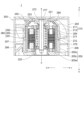
- FIG. 2 is a cross-sectional view of the shaft of the motor shown in FIG. 1 along the direction of axis X;
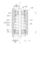
- FIG. 3 is a simplified and enlarged view of the bearing device shown in FIG. 2;
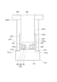
- FIG. 4 is a diagram showing an initial step of the manufacturing process of the bearing device shown in FIG. 3;
- 4 is a diagram showing a middle stage of the manufacturing process of the bearing device shown in FIG. 3.
- FIG. FIG. 4 is a diagram showing the final step of the manufacturing process of the bearing device shown in FIG. 3;
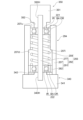
- 4 is a diagram schematically showing a holding member in a modification of the bearing device shown in FIG. 3.
- FIG. 3 is a simplified and enlarged view of the bearing device shown in FIG. 2
- FIG. 4 is a diagram showing an initial step of the manufacturing process of the bearing device shown in FIG. 3
- 4 is a diagram showing a middle stage of the manufacturing process
- FIG. 1 is a perspective view showing the overall configuration of the motor according to the embodiment
- FIG. 2 is a sectional view taken along the direction of the axis X of the motor shown in FIG. 1.
- the motor 1 is configured as an axial fan motor, and functions as an axial blower that blows air in the direction of the axis X. As shown in FIGS. 1 and 2, the motor 1 mainly includes a casing 200, an impeller 210, and a drive section 250.
- the casing 200 has a substantially square cylindrical shape in plan view, and the internal space of the casing 200 extends from the upper end (the upper end in the direction of axis X (direction of arrow a)) to the lower end (the lower end in the direction of axis X). It is a wind tunnel in which air flows toward the end (in the direction of arrow b). That is, an intake port 201 for sucking air into the internal space is formed at the upper end of the casing 200, and an exhaust port for letting air flow out is formed at the lower end of the casing 200.
- the above-described impeller 210, drive unit 250, and the like are housed in the internal space of the casing 200.
- the casing 200 has a side wall 204, a base portion 205, and a fixed wing 206.
- the side wall 204 surrounds the impeller 210 in a radial direction perpendicular to the direction of the axis X (in the direction of arrow cd), and is connected to the upper end.
- the side wall 204 has a cylindrical shape centered on the axis X, and has an inner diameter that does not come into contact with the outer circumferential ends of blades 212 of the impeller 210, which will be described later. That is, a predetermined gap is formed between the outer peripheral end of the blade 212 of the impeller 210 and the inner peripheral surface of the side wall 204.
- the side wall 204 also functions as a guard portion that protects the impeller 210.
- the fixed blade 206 is composed of a plurality of stationary blades, and the side wall 204 and the base portion 205 are connected in the radial direction by the fixed blade 206.
- the base portion 205 includes a disk-shaped lower end portion 205a that is the lower end of the casing 200, and a cylindrical outer periphery that extends upward along the axis X by a predetermined length from the outer peripheral side end of the lower end portion 205a. It includes a wall 205b, and a boss portion 205c that protrudes upward by a predetermined length along the axis X from the inner peripheral end of the lower end portion 205a.
- a fixed blade 206 is integrally formed on the outer peripheral surface of the outer peripheral wall 205b. That is, the outer peripheral wall 205b is supported by the side wall 204 of the casing 200 via the fixed blade 206.
- a bearing housing 207 which will be described later, is attached to the inner peripheral surface of the boss portion 205c of the base portion 205. As will be described later, the bearing housing 207 is part of the bearing device 290 of the drive section 250.
- the side wall 204, base portion 205, and fixed blade 206 of the casing 200 may be integrally formed by injection molding of synthetic resin (for example, polybutylene terephthalate resin (containing glass fiber)). Further, instead of the fixed wings 206 that connect the side wall 204 and the base portion 205, a plurality of spokes made of rod-shaped portions may be used.
- synthetic resin for example, polybutylene terephthalate resin (containing glass fiber)
- each of the upper flange portions 202 and each of the lower flange portions 203 are integrally formed with the side wall 204.
- Each of the upper flange portion 202 and the lower flange portion 203 is provided with a through hole, into which a bolt (not shown) for attachment to a predetermined device or housing is inserted. .
- the impeller 210 includes a hub 211 having a cup shape with a bottom and a substantially inverted U-shaped cross section, and a plurality of blades 212 provided along the circumferential direction on the outer peripheral surface of the hub 211.
- the hub 211 and the plurality of blades 212 may be integrally formed, for example, by injection molding of a synthetic resin (for example, polybutylene terephthalate resin (including glass fiber)).
- the hub 211 is bonded to the upper outer peripheral surface of a rotor yoke 271 (described later) of the drive unit 250 using an adhesive.
- the present invention is not limited to this, and the rotor yoke 271 may be inserted into the hub 211, and the inner peripheral surface of the hub 211 and the outer peripheral surface of the rotor yoke 271 may be integrally formed.
- the hub 211 is formed integrally with the rotor yoke 271.
- the hub 211 covers the upper end of the shaft 277 to prevent foreign matter from entering from the outside.
- a coil spring 223 for applying preload to the first bearing 221 is disposed between the hub 211 and a first bearing 221, which will be described later, in the direction of the axis X.
- the plurality of blades 212 have generally the same shape and are arranged at approximately equal intervals in the circumferential direction of the hub 211.
- the drive section 250 mainly includes a stator section 260, a rotor section 270, and a bearing device 290.
- the bearing device 290 of the drive section 250 is located at the innermost side of the drive section 250.
- FIG. 3 is a simplified and enlarged view of the bearing device 290, and is a sectional view of the bearing device 290 along the direction of the axis X.
- the bearing device 290 mainly includes a shaft 277, a coil spring 209, a first bearing 221, a second bearing 222, and a bearing housing 207.
- the shaft 277 of the bearing device 290 is located at the center of the motor 1, and has the axis X as its central axis.
- the shaft 277 is press-fitted into a bush 273 (described later) of the rotor portion 270, and extends along the direction of the axis X from near the upper end to near the lower end of the motor 1.
- the first bearing 221 and the second bearing 222 of the bearing device 290 have approximately the same configuration and dimensions, and include an inner ring IR, an outer ring OR, and a plurality of balls BA provided between the inner ring IR and the outer ring OR. It is a ball bearing including.
- the first bearing 221 is provided above the second bearing 222, and the second bearing 222 is provided below the first bearing 221.
- Each inner ring IR of the first bearing 221 and the second bearing 222 is press-fitted into the shaft 277. Note that the first bearing 221 and the second bearing 222 are not limited to ball bearings.
- the first bearing 221 supports the upper part of the shaft 277 in the direction of the axis X so that the shaft 277 can rotate
- the second bearing 222 supports the lower part of the shaft 277 in the direction of the axis X. is supported so that the shaft 277 can rotate. That is, the shaft 277 is rotatably supported by the first bearing 221 and the second bearing 222 with respect to the stator section 260.
- the coil spring 209 of the bearing device 290 is arranged between the first bearing 221 and the second bearing 222, and applies pressurization to the first bearing 221 and the second bearing 222.
- the bearing housing 207 of the bearing device 290 is made of a hollow cylindrical metal material, and is press-fitted into the boss portion 205c of the casing 200 at its lower end.
- the bearing housing 207 is supported by the casing 200 and extends in the direction of the axis X.
- the bearing housing 207 is press-fitted into the boss portion 205c.
- the present invention is not limited thereto, and the bearing housing 207 may be formed integrally with the base portion 205 while being inserted into the boss portion 205c.
- the inner circumferential surface 207i of the bearing housing 207 is not flush with the inner circumferential surface 207i, and at least a portion 207f of the inner circumferential surface 207i facing the first bearing 221 is radially inner (radially d side). Therefore, the bearing housing 207 is configured such that the width W1 of the surface of the bearing housing 207 facing the first bearing 221 is larger than the width W2 of the surface of the bearing housing 207 facing the second bearing 222 in the radial direction. ing.
- a step surface 207e extending radially inward from the upper end of the lower surface 207d, and a step surface 207e extending from the radially inner end of the step surface 207e to the upper end of the inner circumferential surface 207i along the direction of the axis X. and an extending upper surface 207u.
- the upper surface 207u includes a portion 207f facing the first bearing 221, and the lower surface 207d includes a portion 207s facing the second bearing 222.
- the distance between the outer circumferential surface of the outer ring OR of the first bearing 221 and the inner circumferential surface 207i of the bearing housing 207 in the radial direction is equal to the outer ring of the second bearing 222.
- the distance is equal to the distance between the outer peripheral surface of the OR and the inner peripheral surface 207i of the bearing housing 207.
- At least the portion 207f of the inner circumferential surface 207i that faces the first bearing 221 protrudes inward in the radial direction, so that the outer ring OR of the first bearing 221 in the radial direction
- the distance between the outer peripheral surface of the outer ring OR of the second bearing 222 and the inner peripheral surface 207i of the bearing housing 207 is smaller than the distance between the outer peripheral surface of the outer ring OR of the second bearing 222 and the inner peripheral surface 207i of the bearing housing 207.
- the gap between the outer circumferential surface of the outer ring OR of the second bearing 222 and the inner circumferential surface 207i of the bearing housing 207 is filled with an adhesive 282, and the outer ring OR of the second bearing 222 is is adhered to the inner peripheral surface 207i of the bearing housing 207.
- the bearing housing 207 and the outer ring OR of the second bearing 222 are bonded to each other so that the angle formed between them is substantially 90°, and the inner ring IR of the second bearing 222 is bonded to the outer ring OR of the second bearing 222 as described above.
- the second bearing 222 is supported by the shaft 277 at a substantially 90° angle with respect to the shaft 277 . That is, in the motor 1, the second bearing 222 is attached substantially perpendicularly to each of the shaft 277 and the bearing housing 207, which extend in the direction of the axis X.
- Adhesive material 281 may be made of the same material as adhesive material 282, or may be made of a different material.
- the adhesive 281 is such that the distance between the outer circumferential surface of the outer ring OR of the first bearing 221 and the inner circumferential surface 207i of the bearing housing 207 is equal to the distance between the outer circumferential surface of the outer ring OR of the second bearing 222 and the inner circumference of the bearing housing 207 in the radial direction. It protrudes to at least one of the upper side and the lower side of the first bearing 221 because it is smaller than the distance from the surface 207i.
- the adhesive 281 includes a first portion 281u that protrudes above the first bearing 221 and a second portion 281d that protrudes below the first bearing 221.
- the outer ring OR of the first bearing 221 is bonded to the inner circumferential surface 207i of the bearing housing 207 by such an adhesive 281.
- the bearing housing 207 and the outer ring OR of the first bearing 221 are bonded to each other such that the angle formed between them is substantially 90°, and the inner ring IR of the first bearing 221 is bonded to the outer ring OR of the first bearing 221 as described above.
- the first bearing 221 By being press-fitted onto the shaft 277, the first bearing 221 is supported by the shaft 277 at an angle of substantially 90° with respect to the shaft 277. That is, in the motor 1, the first bearing 221 is attached substantially perpendicularly to each of the shaft 277 and the bearing housing 207, which extend in the direction of the axis X.
- first bearing 221 and the bearing housing 207 and the second bearing 222 and the bearing housing 207 are fixed using adhesive.
- the present invention is not limited to this, and at least one of the first bearing 221 and the second bearing 222 may be fixed to the bearing housing by other methods, such as fixing via an elastic member or a member having viscous or adhesive properties.
- the bearing housing 207 functions as a holding member that can hold each of the first bearing 221 and the second bearing 222 substantially perpendicular to the shaft 277.
- the stator section 260 of the drive section 250 mainly includes a stator core 261, an insulator 262, and a coil 263.
- the stator core 261 of the stator portion 260 is formed of a laminate in which a plurality of cores of electromagnetic steel sheets made of soft magnetic material are laminated.
- a circular opening is formed in the inner peripheral surface of the stator core 261, and the outer peripheral surface of the bearing housing 207 is fitted into this opening.
- the stator core 261 is attached to the bearing housing 207 and is located on the outside in the radial direction (radial direction c side) with respect to the bearing housing 207.
- stator core 261 may be fixed to bearing housing 207 using an adhesive.
- the insulator 262 of the stator section 260 is made of an insulating material, and is attached to the stator core 261 to cover the stator core 261.
- Coil 263 of stator section 260 is wound around stator core 261 via insulator 262 . In this way, since the coil 263 is wound around the stator core 261 via the insulator 262, the stator core 261 and the coil 263 are insulated by the insulator 262.
- the rotor section 270 of the drive section 250 mainly includes a rotor yoke 271, a magnet 272, and a bush 273.
- the rotor yoke 271 has a hollow cylindrical shape and is made of, for example, a soft magnetic material.
- the rotor yoke 271 is arranged radially outside the coil 263 of the stator section 260.
- the magnet 272 is formed in an annular shape and is arranged on the inner peripheral surface of the rotor yoke 271. That is, the magnet 272 is disposed between the coil 263 of the stator section 260 located on the inside and the rotor yoke 271 located on the outside, and faces the coil 263 in the radial direction.
- the rotor yoke 271 and the magnet 272 are each arranged coaxially with the shaft 277.
- the bush 273 is made of, for example, a soft magnetic material, is connected to the upper end of the rotor yoke 271, and covers the upper part of the rotor yoke 271.
- the bush 273 may be attached to the rotor yoke 271 by integrally fixing the inner peripheral edge of the rotor yoke 271 to the outer peripheral edge of the bush 273 by caulking.
- a recess is formed in the center of the bush 273, and the shaft 277 is press-fitted into this recess.
- the rotor yoke 271 and the magnet 272 are integrated via the hub 211, and the shaft 277 is integrated with the hub 211 via the bush 273.
- the rotor yoke 271 of the rotor portion 270 is attached integrally with the impeller 210. Therefore, in the motor 1 of this embodiment, when the rotor yoke 271 rotates around the shaft 277 due to the electromagnetic action generated between the coil 263 of the stator section 260 and the magnet 272 of the rotor section 270, the impeller 210 rotates together with the rotor yoke 271. It operates as an outer rotor type motor. That is, the rotor section 270 functions as a rotating body by being integrated with the blades 212 by the hub 211 that is attached integrally with the rotor yoke 271.
- the motor 1 includes the shaft 277, the first bearing 221 disposed on one side (upper side) of the shaft 277 in the axis X direction, and the first bearing 221 disposed on the other side (lower side) of the shaft 277 in the axis X direction. ), and a bearing housing 207 (holding member) that holds the first bearing 221 and the second bearing 222, and the first bearing 221 and the bearing housing 207 in the radial direction.
- the distance between the second bearing 222 and the bearing housing 207 is smaller than the distance between the second bearing 222 and the bearing housing 207.
- this motor 1 is configured such that the distance between the first bearing 221 and the bearing housing 207 is smaller than the distance between the second bearing 222 and the bearing housing 207, the method for manufacturing the bearing device 290 described later.
- the first bearing 221 may be installed at an angle with respect to the shaft 277 (that is, the angle between the shaft 277 and the first bearing 221 deviates from 90 degrees). suppressed. Therefore, during operation of the motor 1, load is applied to the first bearing 221 due to the fact that the first bearing 221 is tilted with respect to the shaft 277, and damage to the first bearing 221 as a result is suppressed. Ru.
- the shaft 277 Since the first bearing 221 is prevented from being damaged, the shaft 277 is prevented from tilting due to damage to the first bearing 221. As a result, further damage to the second bearing 222 due to the inclination of the shaft 277 is suppressed. In this way, in the motor 1, damage to the first bearing 221 and the second bearing 222 is suppressed, so that reduction in the life of the motor can be suppressed.
- FIGS. 4 to 6 are cross-sectional views similar to FIG. 3, hatching is omitted for convenience.
- a first jig 310, a second jig 320, and a third jig 330 are prepared and the first step is performed.
- the first jig 310 has a generally cylindrical shape that is flat in the horizontal direction.
- the first jig 310 includes a rectangular first portion 311 that is relatively large in cross-sectional shape along the vertical direction, and a rectangular first portion 311 that is smaller in cross-sectional shape than the first portion 311 in the vertical direction. It consists of a second portion 312.
- the first portion 311 and the second portion 312 are integrated, and the second portion 312 is located above the first portion 311.
- the outer peripheral edge of the first jig 310 is a corner portion 313 where the upper surface 311u of the first portion 311 and the side surface 312s of the second portion 312 form an angle of 90°.
- the diameter of the second portion 312 is substantially the same as the diameter of the lower surface 207d of the inner peripheral surface 207i of the bearing housing 207, and the outer diameter of the second bearing 222 (i.e., the diameter of the outer ring OR of the second bearing 222). diameter) by a predetermined length.
- the second jig 320 has a generally cylindrical shape that is long in the vertical direction, and a protrusion 321 having a cylindrical and ring-shaped outer shape extends downward from the outer edge of the lower end surface of the second jig 320. It stands out.
- the diameter of the second jig 320 is slightly smaller than the diameter of the upper surface 207u of the inner peripheral surface 207i of the bearing housing 207, and approximately equal to the outer diameter of the second bearing 222.
- the third jig 330 has a cylindrical and ring-shaped outer shape, and the inner diameter of the third jig 330 is slightly larger than the diameter of the second jig 320. Therefore, the second jig 320 can pass through the space inside the third jig 330.
- the second bearing 222 with the adhesive 282 applied to the outer circumferential surface (the outer circumferential surface of the outer ring OR) is attached to the second part of the first jig 310. 312 on the upper surface 312u.
- the center of the upper surface 312u of the second portion 312 and the center of the second bearing 222 are made to coincide.
- the protrusion 321 of the second jig 320 is moved to the second It is brought into contact with the bearing 222. In this way, the second bearing 222 is held by the first jig 310 and the second jig 320 from above and below in the vertical direction.
- the third jig 330 is fitted from above to the outside of the second jig 320, and the third jig 330
- the lower surface 330d is brought into contact with the upper surface of the bearing housing 207.
- the bearing housing 207 is held from above and below in the vertical direction by the first jig 310 and the third jig 330, and the bearing housing 207 and the second bearing 222 are held at an angle of 90 degrees. Retained.
- This state is maintained until the adhesive 282 is solidified.
- a first assembly 291 see FIG.
- the first step is a step of vertically fixing the second bearing 222 to the bearing housing 207, which is a holding member.
- the inner circumferential surface of the bearing housing 207 is A certain amount of clearance is formed in the radial direction between the lower surface 207d of the bearing 207i and the outer peripheral surface of the second bearing 222. Therefore, the adhesive 282 filled in this gap is not easily compressed by the inner circumferential surface 207i of the bearing housing 207 and the outer circumferential surface of the second bearing 222, and does not protrude above or below the second bearing 222. There is no, or even if there is, the amount is so small that it can be ignored.
- the second step is performed.
- the fourth jig 340 has a generally cylindrical shape that is flat in the horizontal direction.
- the fourth jig 340 includes a first portion 341 having a relatively large rectangular cross-sectional shape along the vertical direction, and a rectangular first portion 341 having a smaller cross-sectional shape than the first portion 341 along the vertical direction. a second portion 342.
- the first portion 341 and the second portion 342 are integrated, and the second portion 342 is located above the first portion 341.
- the vertical height of the second portion 342 is equal to the vertical length from the lower end of the second bearing 222 to the lower end of the bearing housing 207 in the first assembly 291 .
- the outer diameter of the first portion 341 is larger than the outer diameter of the bearing housing 207.
- the outer diameter of the second portion is larger than the outer diameter of the inner ring IR of the second bearing 222 and smaller than the inner diameter of the outer ring OR.
- An insertion hole 340H that vertically penetrates the second portion 342 is formed at the center of the second portion 342 in the horizontal direction. This insertion hole 340H is formed to have a slightly larger diameter than the shaft 277, and extends to a position in the horizontal center of the first portion 341 and halfway in the vertical direction of the first portion 341. ing.
- the insertion hole 340H of the fourth jig 340 and the inner circumferential surface of the second bearing 222 (inner circumferential surface of the inner ring IR)
- the second bearing 222 of the first assembly 291 is placed on the upper surface of the second portion 342 of the fourth jig 340 so that the second bearing 222 of the first assembly 291 communicates with the defined through hole of the second bearing 222 .
- the inner ring IR of the second bearing 222 is supported from below by the second portion 342 of the fourth jig 340, and the bearing housing 207 of the first assembly 291 is supported from below by the first portion 341 of the fourth jig 340. Supported by
- the shaft 277 is inserted from above into the internal space of the bearing housing 207 of the first assembly 291, and this shaft 277 is press-fitted into the through hole of the second bearing 222.
- the shaft 277 press-fitted into the through hole of the second bearing 222 reaches the lower end of the through hole 340H of the fourth jig 340.
- the inner ring IR of the second bearing 222 is supported by the shaft 277 at an angle of substantially 90° with respect to the shaft 277. That is, this second step results in a second assembly 292 in which the second bearing 222 is mounted substantially perpendicularly to the shaft 277 extending in the direction of the axis X and the bearing housing 207, respectively.
- the third step As shown in FIG. 5, in this third step, the above-mentioned coil spring 209 is inserted into the space between the shaft 277 of the second assembly 292 and the bearing housing 207. The lower end of the coil spring 209 is supported by a second bearing 222 . In this way, a third assembly 293 consisting of the second assembly 292 and the coil spring 209 is obtained. In the vertical direction, the position of the upper end of the coil spring 209 of the third assembly 293 corresponds to the position of the upper surface 207u of the inner peripheral surface 207i of the bearing housing 207.
- the fifth jig 350 has a generally cylindrical shape.
- the fifth jig 350 includes a first portion 351 having a relatively large rectangular cross-sectional shape along the vertical direction, and a rectangular first portion 351 having a smaller cross-sectional shape than the first portion 351 along the vertical direction. It consists of a second portion 352.
- the first portion 351 and the second portion 352 are integrated, and the second portion 352 is located below the first portion 351.
- the outer diameter of the second portion 352 is larger than the outer diameter of the inner ring IR of the first bearing 221 and smaller than the inner diameter of the outer ring OR.
- An insertion hole 350H that vertically penetrates the second portion 352 is formed at the center of the second portion 352 in the horizontal direction. This insertion hole 350H is formed to have a slightly larger diameter than the shaft 277, and extends to a position in the horizontal center of the first portion 351 and halfway in the vertical direction of the first portion 351. ing.
- the upper end of the shaft 277 of the third assembly 293 is inserted into the through hole of the first bearing 221 defined by the inner peripheral surface of the first bearing 221 (the inner peripheral surface of the inner ring IR), and then the fifth The lower surface of the second portion 352 of the jig 350 is brought into contact with the inner ring IR of the first bearing 221. Then, while inserting the shaft 277 into the insertion hole 350H of the fifth jig 350, the fifth jig 350 is pushed down.
- the fifth jig 350 By pushing down the fifth jig 350 while inserting the shaft 277 into the insertion hole 350H, the fifth jig 350 is guided vertically downward, and the inner ring IR of the first bearing 221 is moved by the fifth jig 350. being pushed down. In this way, the first bearing 221 is press-fitted to the upper end of the coil spring 209 of the third assembly 293. Note that, as described above, the upper end of the coil spring 209 corresponds to the position of the upper surface 207u of the inner circumferential surface 207i of the bearing housing 207 in the vertical direction. As a result, the inner ring IR of the first bearing 221 is supported by the shaft 277 at a substantially 90° angle with respect to the shaft 277.
- the fourth step is a step of attaching the inner ring IR of the first bearing 221 to the shaft 277 at an angle of substantially 90 degrees to the shaft 277 to obtain the fourth assembly 294.
- the adhesive 281 is in an unsolidified state.
- the upper surface 207u of the inner circumferential surface 207i of the bearing housing 207 protrudes more radially inward than the lower surface 207d. Therefore, the distance between the upper surface 207u of the inner circumferential surface 207i of the bearing housing 207 and the outer circumferential surface of the first bearing 221 press-fitted into the shaft 277 is the same as that between the lower surface 207d of the inner circumferential surface 207i of the bearing housing 207 and the shaft 277.
- the distance between the second bearing 222 and the outer circumferential surface of the second bearing 222 press-fitted into the second bearing 277 is narrower.
- the first bearing 221 Since the distance between the upper surface 207u and the outer peripheral surface of the first bearing 221 is narrower than the distance between the lower surface 207d and the outer peripheral surface of the second bearing 222, in the fourth step, the first bearing 221
- the adhesive 281 applied to the outer circumferential surface of the first bearing 221 does not fit in the gap between the upper surface 207u and the outer circumferential surface of the first bearing 221, and protrudes to at least one of the upper side and the lower side of the first bearing 221. Note that, for convenience, illustration of the adhesive 281 protruding above and below the first bearing 221 is omitted in FIG. 5 .
- the fifth step is performed. As shown in FIG. 6, in this fifth step, a sixth jig 360 and a seventh jig 370 are used.
- the sixth jig 360 has a generally cylindrical shape that is flat in the horizontal direction.
- the sixth jig 360 includes a first portion 361 having a rectangular cross-sectional shape along the vertical direction, and a cylindrical and ring-shaped second portion 362 that protrudes upward from the upper surface of the first portion 361. are doing.
- the outer diameter of the second portion 362 of the sixth jig 360 is smaller than the diameter of the lower surface 207d of the inner peripheral surface 207i of the bearing housing 207, and the inner diameter of the second portion 362 is the inner diameter of the outer ring OR of the second bearing 222.
- An insertion hole 360H which is slightly larger than the diameter of the shaft 277, is formed in the center of the first portion 361 of the sixth jig 360 in the horizontal direction.
- the seventh jig 370 has a generally cylindrical shape that is flat in the horizontal direction.
- the seventh jig 370 includes a first portion 371 having a rectangular cross-sectional shape along the vertical direction, and a cylindrical and ring-shaped second portion 372 that protrudes downward from the lower surface of the first portion 371. are doing.
- the outer diameter of the second portion 372 of the seventh jig 370 is smaller than the diameter of the upper surface 207u of the inner peripheral surface 207i of the bearing housing 207.
- the inner diameter of the second portion 372 is smaller than the inner diameter of the outer ring OR of the first bearing 221 and larger than the outer diameter of the inner ring IR.
- An insertion hole 370H that is slightly larger than the diameter of the shaft 277 is formed in the center of the first portion 371 of the seventh jig 370 in the horizontal direction.
- the sixth jig 360 is placed on a horizontal surface, and then the shaft 277 of the fourth assembly 294 is fitted into the insertion hole 360H of the sixth jig 360. Thereby, the outer ring OR of the second bearing 222 of the fourth assembly 294 is supported by the sixth jig 360 from below.
- the seventh jig 370 is pushed down while inserting the shaft 277 into the insertion hole 370H of the seventh jig 370.
- the seventh jig 370 is guided vertically downward.
- the lower end of the second portion 372 of the seventh jig 370 eventually comes into contact with the outer ring OR of the first bearing 221.
- the outer ring OR of the first bearing 221 is pressed downward by the seventh jig 370, but on the other hand, the outer ring OR of the first bearing 221 is pressurized upward by the coil spring 209 located below. There is. Therefore, the position of the first bearing 221 in the vertical direction is determined by balancing the pressure from the seventh jig 370 and the preload by the coil spring 209.
- the adhesive 281 eventually solidifies, and the outer peripheral surface of the outer ring OR of the first bearing 221 is adhered to the upper surface 207u of the inner peripheral surface 207i of the bearing housing 207. Furthermore, the portion of the adhesive 281 that has protruded to at least one of the upper and lower sides of the first bearing 221 is also solidified, and at least one of the above-described first portion 281u and second portion 281d of the adhesive 281 is formed.
- the upper surface 207u of the inner circumferential surface 207i of the bearing housing 207 protrudes more radially inward than the lower surface 207d. Therefore, the distance between the upper surface 207u of the inner peripheral surface 207i of the bearing housing 207 and the outer peripheral surface of the first bearing 221 is the same as the distance between the lower surface 207d of the inner peripheral surface 207i of the bearing housing 207 and the outer peripheral surface of the second bearing 222. narrower than the distance between. Therefore, even if the outer ring OR of the first bearing 221 tries to tilt with respect to the shaft 277 or the bearing housing 207 due to the elastic force of the coil spring 209 during the fifth step, the outer ring OR immediately contacts the upper surface 207u. Such an inclination is suppressed. As a result, in the fifth step, the angles formed by the outer ring OR of the first bearing 221 and each of the shaft 277 and the bearing housing 207 are prevented from deviating from 90°.
- the first bearing 221 is attached to each of the shaft 277 and the bearing housing 207 at a substantially 90° angle, and the bearing device 290 is completed.
- the motor of the present invention has been described above with reference to preferred embodiments, the motor of the present invention is not limited to the configuration of the above embodiments.
- the bearing housing 207 of the above embodiment is It is not limited.
- a bearing housing 1207 according to a modified example as shown in FIG. 7 may be configured.
- the inner peripheral surface 1207i of the bearing housing 1207 has a lower surface 1207d extending along the direction of the axis X from the lower end of the inner peripheral surface 1207i to approximately half the height of the inner peripheral surface 1207i, and a lower surface 1207d.
- a first stepped surface 1207e1 extending radially inward from the upper end, an upper surface 1207u extending along the axis X from the upper end of the inner peripheral surface 1207i to near the upper end of the inner peripheral surface 1207i, and A second step surface 1207e2 extends radially inward from the lower end, and a second step surface 1207e2 extends in the direction of the axis X from the radially inner end of the first step surface 1207e1 to the radially inner end of the second step surface 1207e2. It consists of a protruding surface 1207m extending along.
- the protruding surface 1207m includes a portion 1207f facing the first bearing 221, and the lower surface 1207d includes a portion 1207s facing the second bearing 222.
Landscapes
- Engineering & Computer Science (AREA)
- Power Engineering (AREA)
- Mounting Of Bearings Or Others (AREA)
- Motor Or Generator Frames (AREA)
- Connection Of Motors, Electrical Generators, Mechanical Devices, And The Like (AREA)
Abstract
Description
Claims (5)
- シャフトと、
前記シャフトの軸方向一方側に配置される第1軸受と、
前記シャフトの軸方向他方側に配置される第2軸受と、
前記第1軸受と前記第2軸受とを保持する保持部材と、
を備え、
径方向において、前記第1軸受と前記保持部材との間の距離は、前記第2軸受と前記保持部材との距離よりも小さい、
モータ。 - 径方向において、前記保持部材の前記第1軸受に対向する面の幅は、前記保持部材の前記第2軸受に対向する面の幅よりも大きい、
請求項1に記載のモータ。 - 前記第1軸受の軸方向他方側に接着材が配置され、前記第1軸受と前記保持部材とが当該接着材によって接着される、
請求項1または2に記載のモータ。 - 前記第1軸受の軸方向一方側に接着材が配置され、前記第1軸受と前記保持部材とが当該接着材によって接着される、
請求項1から3のいずれか1項に記載のモータ。 - 前記第2軸受と前記保持部材とは、接着材で接着される、
請求項1から4のいずれか1項に記載のモータ。
Priority Applications (1)
| Application Number | Priority Date | Filing Date | Title |
|---|---|---|---|
| US18/850,768 US20250226718A1 (en) | 2022-03-28 | 2022-12-19 | Motor |
Applications Claiming Priority (2)
| Application Number | Priority Date | Filing Date | Title |
|---|---|---|---|
| JP2022052301A JP2023145036A (ja) | 2022-03-28 | 2022-03-28 | モータ |
| JP2022-052301 | 2022-03-28 |
Publications (1)
| Publication Number | Publication Date |
|---|---|
| WO2023188597A1 true WO2023188597A1 (ja) | 2023-10-05 |
Family
ID=88200050
Family Applications (1)
| Application Number | Title | Priority Date | Filing Date |
|---|---|---|---|
| PCT/JP2022/046607 Ceased WO2023188597A1 (ja) | 2022-03-28 | 2022-12-19 | モータ |
Country Status (3)
| Country | Link |
|---|---|
| US (1) | US20250226718A1 (ja) |
| JP (1) | JP2023145036A (ja) |
| WO (1) | WO2023188597A1 (ja) |
Families Citing this family (1)
| Publication number | Priority date | Publication date | Assignee | Title |
|---|---|---|---|---|
| WO2026070835A1 (ja) * | 2024-09-27 | 2026-04-02 | ミネベアミツミ株式会社 | 送風装置 |
Citations (3)
| Publication number | Priority date | Publication date | Assignee | Title |
|---|---|---|---|---|
| JP2000262004A (ja) * | 1999-03-05 | 2000-09-22 | Nec Corp | スピンドルモータ |
| JP2019134526A (ja) * | 2018-01-29 | 2019-08-08 | 日本電産株式会社 | モータ、及び、シーリングファン |
| JP2019143516A (ja) * | 2018-02-20 | 2019-08-29 | 三菱電機株式会社 | ファンモータの製造方法、ファンモータ及び掃除機 |
-
2022
- 2022-03-28 JP JP2022052301A patent/JP2023145036A/ja active Pending
- 2022-12-19 WO PCT/JP2022/046607 patent/WO2023188597A1/ja not_active Ceased
- 2022-12-19 US US18/850,768 patent/US20250226718A1/en active Pending
Patent Citations (3)
| Publication number | Priority date | Publication date | Assignee | Title |
|---|---|---|---|---|
| JP2000262004A (ja) * | 1999-03-05 | 2000-09-22 | Nec Corp | スピンドルモータ |
| JP2019134526A (ja) * | 2018-01-29 | 2019-08-08 | 日本電産株式会社 | モータ、及び、シーリングファン |
| JP2019143516A (ja) * | 2018-02-20 | 2019-08-29 | 三菱電機株式会社 | ファンモータの製造方法、ファンモータ及び掃除機 |
Also Published As
| Publication number | Publication date |
|---|---|
| JP2023145036A (ja) | 2023-10-11 |
| US20250226718A1 (en) | 2025-07-10 |
Similar Documents
| Publication | Publication Date | Title |
|---|---|---|
| US9062567B2 (en) | Fan | |
| KR100421103B1 (ko) | 디스크 재치부를 구비한 스핀들 모터 | |
| US20070189892A1 (en) | Axial flow fan and housing for the same | |
| JP2018125920A (ja) | アウターロータ型モータ | |
| JPH11132193A (ja) | 軸流型送風機 | |
| CN101809481A (zh) | 多面反射体扫描电动机 | |
| CN209313594U (zh) | 马达和吊扇 | |
| JP2023145036A (ja) | モータ | |
| US8629593B2 (en) | Spindle motor with sleeve holder including cylindrical part, seating part, and coupling part | |
| US20200309191A1 (en) | Gas dynamic pressure bearing, motor, and fan motor | |
| JP2023145035A (ja) | モータ | |
| JPH11223195A (ja) | 軸流ファンの回転子 | |
| JP3318075B2 (ja) | スピンドルモータ | |
| US20260039161A1 (en) | Motor | |
| JP6816546B2 (ja) | モータおよびモータの製造方法 | |
| JP2844379B2 (ja) | スピンドルモータ | |
| JP2003324891A (ja) | モータ | |
| US9135945B2 (en) | Disk rotating motor comprising bracket including cylindrical portion and folded portion | |
| JP2002051525A (ja) | ステッピングモータ及びそのロータ | |
| JPH0713416Y2 (ja) | 軸流ファンモータ | |
| WO2024257820A1 (ja) | 送風装置 | |
| JP2021191132A (ja) | モータ | |
| JP2010175046A5 (ja) | ||
| JP7216585B2 (ja) | 遠心ファン | |
| WO2023189560A1 (ja) | モータ、ファンおよび軸受装置 |
Legal Events
| Date | Code | Title | Description |
|---|---|---|---|
| 121 | Ep: the epo has been informed by wipo that ep was designated in this application |
Ref document number: 22935725 Country of ref document: EP Kind code of ref document: A1 |
|
| NENP | Non-entry into the national phase |
Ref country code: DE |
|
| WWE | Wipo information: entry into national phase |
Ref document number: 18850768 Country of ref document: US |
|
| 122 | Ep: pct application non-entry in european phase |
Ref document number: 22935725 Country of ref document: EP Kind code of ref document: A1 |
|
| WWP | Wipo information: published in national office |
Ref document number: 18850768 Country of ref document: US |