WO2023188478A1 - 計測装置 - Google Patents
計測装置 Download PDFInfo
- Publication number
- WO2023188478A1 WO2023188478A1 PCT/JP2022/038078 JP2022038078W WO2023188478A1 WO 2023188478 A1 WO2023188478 A1 WO 2023188478A1 JP 2022038078 W JP2022038078 W JP 2022038078W WO 2023188478 A1 WO2023188478 A1 WO 2023188478A1
- Authority
- WO
- WIPO (PCT)
- Prior art keywords
- light
- measuring device
- intensity
- optical
- interference
- Prior art date
- Legal status (The legal status is an assumption and is not a legal conclusion. Google has not performed a legal analysis and makes no representation as to the accuracy of the status listed.)
- Ceased
Links
Images






Classifications
-
- G—PHYSICS
- G01—MEASURING; TESTING
- G01S—RADIO DIRECTION-FINDING; RADIO NAVIGATION; DETERMINING DISTANCE OR VELOCITY BY USE OF RADIO WAVES; LOCATING OR PRESENCE-DETECTING BY USE OF THE REFLECTION OR RERADIATION OF RADIO WAVES; ANALOGOUS ARRANGEMENTS USING OTHER WAVES
- G01S7/00—Details of systems according to groups G01S13/00, G01S15/00, G01S17/00
- G01S7/48—Details of systems according to groups G01S13/00, G01S15/00, G01S17/00 of systems according to group G01S17/00
- G01S7/491—Details of non-pulse systems
- G01S7/4911—Transmitters
-
- G—PHYSICS
- G01—MEASURING; TESTING
- G01S—RADIO DIRECTION-FINDING; RADIO NAVIGATION; DETERMINING DISTANCE OR VELOCITY BY USE OF RADIO WAVES; LOCATING OR PRESENCE-DETECTING BY USE OF THE REFLECTION OR RERADIATION OF RADIO WAVES; ANALOGOUS ARRANGEMENTS USING OTHER WAVES
- G01S17/00—Systems using the reflection or reradiation of electromagnetic waves other than radio waves, e.g. lidar systems
- G01S17/02—Systems using the reflection of electromagnetic waves other than radio waves
- G01S17/06—Systems determining position data of a target
- G01S17/08—Systems determining position data of a target for measuring distance only
- G01S17/32—Systems determining position data of a target for measuring distance only using transmission of continuous waves, whether amplitude-, frequency-, or phase-modulated, or unmodulated
- G01S17/34—Systems determining position data of a target for measuring distance only using transmission of continuous waves, whether amplitude-, frequency-, or phase-modulated, or unmodulated using transmission of continuous, frequency-modulated waves while heterodyning the received signal, or a signal derived therefrom, with a locally-generated signal related to the contemporaneously transmitted signal
-
- G—PHYSICS
- G01—MEASURING; TESTING
- G01S—RADIO DIRECTION-FINDING; RADIO NAVIGATION; DETERMINING DISTANCE OR VELOCITY BY USE OF RADIO WAVES; LOCATING OR PRESENCE-DETECTING BY USE OF THE REFLECTION OR RERADIATION OF RADIO WAVES; ANALOGOUS ARRANGEMENTS USING OTHER WAVES
- G01S17/00—Systems using the reflection or reradiation of electromagnetic waves other than radio waves, e.g. lidar systems
- G01S17/02—Systems using the reflection of electromagnetic waves other than radio waves
- G01S17/50—Systems of measurement based on relative movement of target
- G01S17/58—Velocity or trajectory determination systems; Sense-of-movement determination systems
-
- G—PHYSICS
- G01—MEASURING; TESTING
- G01S—RADIO DIRECTION-FINDING; RADIO NAVIGATION; DETERMINING DISTANCE OR VELOCITY BY USE OF RADIO WAVES; LOCATING OR PRESENCE-DETECTING BY USE OF THE REFLECTION OR RERADIATION OF RADIO WAVES; ANALOGOUS ARRANGEMENTS USING OTHER WAVES
- G01S7/00—Details of systems according to groups G01S13/00, G01S15/00, G01S17/00
- G01S7/48—Details of systems according to groups G01S13/00, G01S15/00, G01S17/00 of systems according to group G01S17/00
- G01S7/481—Constructional features, e.g. arrangements of optical elements
- G01S7/4811—Constructional features, e.g. arrangements of optical elements common to transmitter and receiver
-
- G—PHYSICS
- G01—MEASURING; TESTING
- G01S—RADIO DIRECTION-FINDING; RADIO NAVIGATION; DETERMINING DISTANCE OR VELOCITY BY USE OF RADIO WAVES; LOCATING OR PRESENCE-DETECTING BY USE OF THE REFLECTION OR RERADIATION OF RADIO WAVES; ANALOGOUS ARRANGEMENTS USING OTHER WAVES
- G01S7/00—Details of systems according to groups G01S13/00, G01S15/00, G01S17/00
- G01S7/48—Details of systems according to groups G01S13/00, G01S15/00, G01S17/00 of systems according to group G01S17/00
- G01S7/481—Constructional features, e.g. arrangements of optical elements
- G01S7/4814—Constructional features, e.g. arrangements of optical elements of transmitters alone
-
- G—PHYSICS
- G01—MEASURING; TESTING
- G01S—RADIO DIRECTION-FINDING; RADIO NAVIGATION; DETERMINING DISTANCE OR VELOCITY BY USE OF RADIO WAVES; LOCATING OR PRESENCE-DETECTING BY USE OF THE REFLECTION OR RERADIATION OF RADIO WAVES; ANALOGOUS ARRANGEMENTS USING OTHER WAVES
- G01S7/00—Details of systems according to groups G01S13/00, G01S15/00, G01S17/00
- G01S7/48—Details of systems according to groups G01S13/00, G01S15/00, G01S17/00 of systems according to group G01S17/00
- G01S7/481—Constructional features, e.g. arrangements of optical elements
- G01S7/4816—Constructional features, e.g. arrangements of optical elements of receivers alone
-
- G—PHYSICS
- G01—MEASURING; TESTING
- G01S—RADIO DIRECTION-FINDING; RADIO NAVIGATION; DETERMINING DISTANCE OR VELOCITY BY USE OF RADIO WAVES; LOCATING OR PRESENCE-DETECTING BY USE OF THE REFLECTION OR RERADIATION OF RADIO WAVES; ANALOGOUS ARRANGEMENTS USING OTHER WAVES
- G01S7/00—Details of systems according to groups G01S13/00, G01S15/00, G01S17/00
- G01S7/48—Details of systems according to groups G01S13/00, G01S15/00, G01S17/00 of systems according to group G01S17/00
- G01S7/497—Means for monitoring or calibrating
-
- G—PHYSICS
- G01—MEASURING; TESTING
- G01S—RADIO DIRECTION-FINDING; RADIO NAVIGATION; DETERMINING DISTANCE OR VELOCITY BY USE OF RADIO WAVES; LOCATING OR PRESENCE-DETECTING BY USE OF THE REFLECTION OR RERADIATION OF RADIO WAVES; ANALOGOUS ARRANGEMENTS USING OTHER WAVES
- G01S17/00—Systems using the reflection or reradiation of electromagnetic waves other than radio waves, e.g. lidar systems
- G01S17/88—Lidar systems specially adapted for specific applications
- G01S17/93—Lidar systems specially adapted for specific applications for anti-collision purposes
- G01S17/931—Lidar systems specially adapted for specific applications for anti-collision purposes of land vehicles
Definitions
- the present disclosure relates to a measuring device.
- a typical measurement device using LiDAR technology includes a light source, a photodetector, and processing circuitry.
- the light source emits light to illuminate an object.
- a photodetector detects a reflected wave from an object and outputs a signal corresponding to the time delay of the reflected wave.
- the processing circuit generates measurement data regarding the distance and velocity of the object based on the signal output from the photodetector using, for example, FMCW (Frequency Modulated Continuous Wave) technology.
- FMCW Frequency Modulated Continuous Wave
- the intensity of the laser light emitted to the outside from the measuring device is classified into classes according to, for example, JIS (Japanese Industrial Standards) C6802 "Safety Standards for Laser Products.” From the viewpoint of eye safety, ie, eye safety, it is desirable that the intensity of the laser beam emitted to the outside is equal to or lower than the upper limit of the intensity of class 1.
- the present disclosure provides a measuring device that can appropriately adjust the intensity of light emitted to the outside and expand the distance range in which distance measurement and/or speed measurement of an object can be performed.
- a measuring device includes an interference optical system including a light source that emits light and a light splitter that separates the light emitted from the light source into reference light and irradiation light for irradiating an object.
- an interference optical system that generates interference light by causing reflected light generated when at least a part of the irradiated light is reflected by the object and the reference light to interfere with each other, and emits the at least part of the irradiated light.
- at least one optical element that detects the interference light a first photodetector that detects the interference light, a part of the light emitted from the light source, a part of the irradiation light in the interference optical system, or the interference optical system.
- a second photodetector that detects monitor light that is part of the reference light; and a processing circuit that adjusts the intensity of the irradiation light that is emitted to the outside based on the intensity of the monitor light.
- the general or specific aspects of the present disclosure may be implemented in a system, apparatus, method, integrated circuit, computer program or recording medium such as a computer readable recording disk, and the system, apparatus, method, integrated circuit, It may be realized by any combination of a computer program and a recording medium.
- the computer-readable recording medium may include, for example, a non-volatile recording medium such as a CD-ROM (Compact Disc-Read Only Memory).
- a device may be composed of one or more devices. When the device is composed of two or more devices, the two or more devices may be placed within one device, or may be separately placed within two or more separate devices.
- “device” may refer not only to a device, but also to a system of devices.
- the technology of the present disclosure it is possible to realize a measuring device that can appropriately adjust the intensity of light emitted to the outside and expand the distance range in which distance measurement and/or speed measurement of an object can be performed.
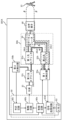
- FIG. 1 is a block diagram schematically showing the configuration of a measuring device according to exemplary embodiment 1 of the present disclosure.
- FIG. 2 is a diagram schematically showing temporal changes in the frequencies of the reference light and reflected light when the object is stationary.
- FIG. 3 is a flowchart schematically showing an example of a measurement operation performed by the processing circuit.
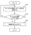
- FIG. 4 is a flowchart schematically showing an example of the operation performed by the determination circuit.
- FIG. 5 is a diagram schematically showing an example of a spectrum of a detection signal.
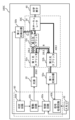
- FIG. 6 is a block diagram schematically showing the configuration of a measuring device in a comparative example.
- FIG. 7A is a graph showing the spectrum of the detection signal in the example.
- FIG. 7B is a graph showing the spectrum of the detection signal in the comparative example.
- FIG. 8 is a block diagram schematically showing the configuration of a measuring device according to exemplary embodiment 2 of the present disclosure.
- FIG. 9 is a block diagram schematically showing the configuration of a measuring device according to exemplary embodiment 3 of the present disclosure.
- FIG. 10 is a block diagram schematically showing the configuration of a measuring device according to exemplary embodiment 4 of the present disclosure.
- FIG. 11 is a block diagram schematically showing the configuration of a measuring device according to exemplary embodiment 5 of the present disclosure.
- FIG. 12 is a block diagram schematically showing the configuration of a measuring device according to exemplary embodiment 6 of the present disclosure.
- FIG. 13 is a block diagram schematically showing the configuration of a measuring device according to exemplary embodiment 7 of the present disclosure.
- FIG. 14 is a block diagram schematically showing the configuration of a measuring device according to exemplary embodiment 8 of the present disclosure.
- FIG. 15 is a block diagram schematically showing the configuration of a measuring device according to exemplary embodiment 9 of the present disclosure.
- all or part of a circuit, unit, device, member, or section, or all or part of a functional block in a block diagram may be, for example, a semiconductor device, a semiconductor integrated circuit (IC), or a large scale integration (LSI). ) may be implemented by one or more electronic circuits.
- An LSI or IC may be integrated into one chip, or may be configured by combining a plurality of chips.
- functional blocks other than the memory element may be integrated into one chip.
- it is called LSI or IC, but the name changes depending on the degree of integration, and may be called system LSI, VLSI (very large scale integration), or ULSI (ultra large scale integration).
- a field programmable gate array (FPGA), which is programmed after the LSI is manufactured, or a reconfigurable logic device that can reconfigure the connections inside the LSI or set up circuit sections inside the LSI can also be used for the same purpose.
- FPGA field programmable gate array
- the functions or operations of all or part of a circuit, unit, device, member, or section can be performed by software processing.
- the software is recorded on one or more non-transitory storage media such as ROM, optical disk, hard disk drive, etc., and when the software is executed by a processor, the functions specified by the software are executed. It is executed by a processor and peripheral devices.
- a system or apparatus may include one or more non-transitory storage media on which software is recorded, a processor, and required hardware devices, such as interfaces.
- light includes not only visible light (wavelength of about 400 nm to about 700 nm) but also electromagnetic waves including ultraviolet light (wavelength of about 10 nm to about 400 nm) and infrared light (wavelength of about 700 nm to about 1 mm). means.
- ultraviolet light is also referred to as “ultraviolet light” and infrared light is also referred to as “infrared light.”
- FMCW-LiDAR technology has been developed that has both a wide dynamic range and high resolution in terms of distance, is less susceptible to external disturbances, and can detect the speed of objects moving at high speed.
- the spot diameter of the light that illuminates the object can be made relatively small, making it possible to more accurately obtain measurement data on the object.
- Patent Document 1 discloses a method for accurately measuring distance by using internally scattered light generated by an optical antenna that emits light to the outside as a trigger for starting measurement.
- the internally scattered light disclosed in Patent Document 1 can be used to improve distance measurement accuracy.
- a measuring device using FMCW-LiDAR technology may be provided with a monitoring photodetector that detects part of the light within the measuring device as monitor light.
- the intensity of the laser beam emitted to the outside can be confirmed from the intensity of the detected monitor light, and the intensity of the laser beam emitted to the outside can be adjusted appropriately so that it is below the upper limit of class 1 intensity. be able to.
- the inventor discovered that depending on the arrangement of the monitoring photodetector, internally scattered light due to the monitoring photodetector may occur in addition to the above-mentioned internally scattered light. It has been found that light may narrow the distance range in which distance measurement and/or speed measurement of objects can be performed.
- a measurement device using FMCW-LiDAR technology, by appropriately arranging the monitoring photodetector, it is possible to reduce the influence of internally scattered light caused by the monitoring photodetector. can. As a result, it becomes possible to appropriately adjust the intensity of the light emitted to the outside and widen the distance range in which distance measurement and/or speed measurement of an object can be performed.
- a measurement device according to an embodiment of the present disclosure will be described.
- the measuring device is an interference optical system including a light source that emits light and a light splitter that separates the light emitted from the light source into reference light and irradiation light for irradiating an object.
- an interference optical system that generates interference light by causing reflected light generated when at least a part of the irradiated light is reflected by the object and the reference light to interfere; and an interference optical system that emits the at least part of the irradiated light.
- a second photodetector that detects monitor light that is part of the reference light
- a processing circuit that controls the operation of the light source and processes signals from the first photodetector and the second photodetector. and a processing circuit that causes the light source to change the intensity of the light based on the intensity of the monitor light.
- this measuring device it is possible to appropriately adjust the intensity of the light emitted to the outside and expand the distance range in which distance measurement and/or speed measurement of an object can be performed.
- the measuring device according to the second item is the measuring device according to the first item, further comprising another optical splitter between the light source and the optical splitter.
- the other optical splitter separates the monitor light from the light emitted from the light source.
- a part of the light emitted from the light source can be used as monitor light via another optical splitter.
- a measuring device is the measuring device according to the first item, in which the second photodetector converts the monitor light from the light emitted from the light source without passing through another light splitter. To detect.
- a part of the light emitted from the light source can be used as monitor light without going through another optical splitter.
- the measuring device is the measuring device according to the first item, wherein the interference optical system further includes another optical splitter.
- the other optical splitter separates the monitor light from the irradiation light in the interference optical system.
- a part of the irradiation light in the interference optical system can be used as monitor light.
- the measuring device according to the fifth item is the measuring device according to the first item, wherein the interference optical system further includes another optical splitter.
- the other optical splitter separates the monitor light from the reference light in the interference optical system.
- a part of the reference light in the interference optical system can be used as monitor light.
- the measuring device is the measuring device according to any one of the first to fifth items, in which the interference optical system is connected to a circulator or a circulator connected to the optical splitter and the at least one optical element. Equipped with an optical splitter.
- interference light can be generated by a circulator or another optical splitter.
- the measuring device is the measuring device according to any one of the first to sixth items, wherein the at least one optical element includes a plurality of optical elements. Each of the plurality of optical elements emits a part of the irradiation light.
- the measuring device is the measuring device according to any one of the first to seventh items, wherein the at least one optical element receives the reflected light and transmits the reflected light to the interference optical system. input.
- the configuration can be simplified by using a coaxial optical system, and stable measurement can be achieved.
- the measuring device is the measuring device according to any one of the first to seventh items, wherein at least one other optical system receives the reflected light and inputs the reflected light into the interference optical system.
- the device further includes an element.
- this measurement device does not employ a coaxial optical system, it does not require an optical circulator that generates interference light and other circulators, so manufacturing costs can be kept low.
- the measuring device is the measuring device according to any one of the first to ninth items, wherein the processing circuit makes a determination to compare the intensity of the monitor light and a predetermined intensity, and the determination result is and a drive circuit that causes the light source to change the intensity of the light based on the limit signal.
- the intensity of the light emitted to the outside can be appropriately adjusted.
- the measuring device is the measuring device according to any one of the first to ninth items, further comprising a shutter that opens and closes the optical path of the light emitted from the light source or the irradiation light.
- the processing circuit includes a determination circuit that performs a determination by comparing the intensity of the monitor light with a predetermined intensity, and outputs a restriction signal based on the determination result.
- the shutter opens and closes the optical path based on the restriction signal.
- the intensity of the light emitted to the outside can be appropriately adjusted by opening and closing the optical path of the light emitted from the light source using a shutter.
- the measuring device is the measuring device according to any one of the first to eleventh items, in which the light source can change the frequency of the light over time.
- the processing circuit processes the signal output from the first photodetector. This measurement device can measure the distance and/or speed of an object using FMCW-LiDAR technology.
- FIG. 1 is a block diagram schematically showing the configuration of a measuring device according to exemplary embodiment 1 of the present disclosure.
- a person is shown as an object 10 to be measured.
- the object 10 may be any object other than a person, such as a vehicle or a building.
- the measuring device 100A shown in FIG. 1 includes a light source 20, an interference optical system 30A, an optical element 40, and a first photodetector 50a.
- the interference optical system 30A includes a first optical splitter 32a, a second optical splitter 32b, and an optical circulator 34.
- the measuring device 100A further includes a third optical splitter 32c and a second photodetector 50b.
- the measuring device 100A further includes a processing circuit 60 that controls the operation of the light source 20 and processes signals from the first photodetector 50a and the second photodetector 50, and a memory 62.
- the measuring device 100A may further include components other than those illustrated.
- the thick lines shown in FIG. 1 represent optical fibers connecting two components to each other.
- Solid lines with arrows shown in FIG. 1 represent signal transmission and reception.
- the dashed lines with arrows shown in FIG. 1 represent the flow of light.
- the first optical splitter 32a is also simply referred to as an "optical splitter”
- the third optical splitter 32c is also referred to as “another optical splitter”.
- the third optical splitter 32c and the second photodetector 50b can detect the light inside the measuring device 100A as monitor light. As a result, it becomes possible to appropriately adjust the intensity of the irradiation light emitted to the outside based on the intensity of the detected monitor light.
- the third optical splitter 32c and the second photodetector 50b do not affect the distance range in which distance measurement and/or speed measurement of an object can be performed.
- the components of the measuring device 100A will be explained below. First, details of the light source 20, interference optical system 30A, optical element 40, and first photodetector 50a used for the FMCW-LiDAR technique in the measuring device 100A will be described.
- the light source 20 emits laser light 20L0.
- the light source 20 can change the frequency of the laser beam 20L0.
- the frequency can be changed over time in a constant time period, for example in a triangular wave shape or a sawtooth shape.
- the time period may be, for example, 1 ⁇ sec or more and 10 msec or less.
- the time period may vary.
- the frequency change width may be, for example, 100 MHz or more and 1 THz or less.
- the wavelength of the laser beam 20L0 may be included in the near-infrared wavelength range of, for example, 700 nm or more and 2000 nm or less.
- Sunlight has near-infrared light and visible light, and the amount of near-infrared light is smaller than the amount of visible light. Therefore, if near-infrared light is used as the laser light 20L0, the influence of sunlight as noise can be reduced.
- the wavelength of the laser beam 20L0 does not necessarily need to be included in the wavelength range of near-infrared light.
- the wavelength of the laser beam 20L0 may be included in the wavelength range of visible light from 400 nm to 700 nm, or may be included in the wavelength range of ultraviolet light.
- the light source 20 may include, for example, a distributed feedback (DFB) laser diode or an external cavity (EC) laser diode.
- DFB distributed feedback
- EC external cavity
- These laser diodes are inexpensive and small, capable of single mode oscillation, and can modulate the frequency of the laser light 20L0 according to the amount of current applied. If a laser diode capable of emitting high-power laser light is used as the light source 20, the frequency of the laser light 20L0 can be stably modulated. However, the intensity of the laser beam 20L0 emitted from the light source 20 is adjusted so that the intensity of the laser beam emitted to the outside is equal to or less than the upper limit of the intensity of class 1.
- the light source 20 is connected to the third optical splitter 32c.
- An attenuator that adjusts the intensity of the laser beam 20L0 may be disposed between the light source 20 and the third optical splitter 32c.
- the first light splitter 32a included in the interference optical system 30A separates the laser light 20L0 emitted from the light source 20 and passing through the third light splitter into a reference light 20L1 and an irradiation light 20L2 for irradiating the object 10. do.
- the intensity of the reference light 20L1 may be, for example, 1% or more and 10% or less of the intensity of the laser beam 20L0 input to the first optical splitter 32a.
- the first optical splitter 32a inputs the reference light 20L1 to the second optical splitter 32b, and inputs the irradiation light 20L2 to the optical circulator 34.
- the first optical splitter 32a is connected to a second optical splitter 32b, a third optical splitter 32c, and an optical circulator 34.
- the optical circulator 34 included in the interference optical system 30A inputs the irradiated light 20L2 to the optical element 40, and inputs the reflected light 20L3 generated when the irradiated light 20L2 is reflected by the object 10 to the second optical splitter 32b.
- the optical circulator 34 is connected to the first optical splitter 32a, the second optical splitter 32b, and the optical element 40.
- the second optical splitter 32b included in the interference optical system 30A inputs interference light 20L4, which is obtained by superimposing and interfering the reference light 20L1 and the reflected light 20L3, to the first photodetector 50a.
- the second optical splitter 32b is connected to the first optical splitter 32a, the optical circulator 34, and the first photodetector 50a.
- the optical element 40 emits the irradiation light 20L2 to the outside.
- the optical element 40 further receives the reflected light 20L3 and inputs the reflected light 20L3 to the optical circulator 34 included in the interference optical system 30A.
- the direction in which the irradiation light 20L2 is emitted from the optical element 40 is also referred to as "front".
- the optical element 40 may be, for example, a collimator lens that collimates the irradiated light 20L2.
- collimator lens collimates the irradiated light 20L2.
- “collimating” means not only the case where the irradiated light 20L2 is made into parallel light, but also the case where the spread of the irradiated light 20L2 is reduced.
- the optical element 40 may be a condenser lens that focuses the irradiated light 20L2, or may be a diffuser lens that diffuses the irradiated light 20L2.
- the optical element 40 may be a diffraction grating that outputs the irradiated light 20L2 to the outside as 0th-order diffracted light and/or ⁇ Nth-order diffracted light (N is a natural number).
- the optical element 40 may have a configuration that combines at least two of a collimator lens, a condensing lens, a diffusing lens, and a diffraction grating. In the following description, it is assumed that the optical element 40 is a collimator lens.
- the path of the irradiated light 20L2 from the interference optical system 30A to the object 10 and the path of the reflected light 20L3 from the object 10 to the interference optical system 30A overlap with each other.
- the configuration of the measuring device 100A can be simplified and stable measurement can be achieved.
- the first photodetector 50a detects the interference light 20L4 and outputs a signal according to the intensity of the interference light 20L4.
- the first photodetector 50a includes one or more photodetecting elements.
- the photodetector element outputs a signal corresponding to the intensity of the interference light 20L4.
- the third optical splitter 32c separates the laser beam 20L0 emitted from the light source 20, inputs part of it to the second photodetector 50b, and inputs the remaining part to the first optical splitter 32a.
- the intensity of the part of the laser beam 20L0 may be, for example, 1% or more and 10% or less of the intensity of the laser beam 20L0 input to the third optical splitter 32c.
- the third optical splitter 32c is connected to the light source 20 and the first optical splitter 32a. When the laser beam 20L0 propagates through the air instead of through an optical fiber, a beam sampler may be used instead of the third optical splitter 32c.
- the second photodetector 50b detects the monitor light that is part of the laser light 20L0 separated by the third optical splitter 32c, and outputs a signal corresponding to the intensity of the monitor light.
- the intensity of the irradiation light 20L2 emitted to the outside can be confirmed from the intensity of the monitor light.
- the reason for checking the intensity of the irradiation light 20L2 emitted to the outside is as follows. As described above, from the viewpoint of stably modulating the frequency of the laser light 20L0, a laser diode capable of emitting high-power laser light may be used as the light source 20. When such a laser diode is used, the intensity of the irradiated light 20L2 emitted to the outside may exceed the upper limit of the class 1 intensity due to, for example, a failure or malfunction.
- the intensity of the laser beam 20L0 emitted from the light source 20 is adjusted so that the intensity of the irradiated light 20L2 emitted to the outside is below the upper limit of the intensity of class 1. can do.
- Patent Documents 1 and 2 and Non-Patent Document 1 do not describe stably modulating the frequency of the laser light 20L0 using a laser diode capable of emitting high-power laser light. Further, there is no description of providing a monitoring photodetector to check the intensity of the irradiated light 20L2 emitted to the outside.
- the processing circuit 60 includes a control circuit 60a, a drive circuit 60b, a determination circuit 60c, and a signal processing circuit 60d.
- the control circuit 60a controls the operation of the drive circuit 60b, the signal processing circuit 60d, the first photodetector 50a, and the second photodetector 50b.
- each operation of the control circuit 60a, drive circuit 60b, determination circuit 60c, and signal processing circuit 60d may be described as the operation of the processing circuit 60.
- the drive circuit 60b drives the light source 20. It can also be said that the control circuit 60a controls the operation of the light source 20 via the drive circuit 60b.
- the determination circuit 60c performs determination by comparing the intensity of the monitor light detected by the second photodetector 50b with a predetermined intensity, and outputs a restriction signal based on the determination result.
- the drive circuit 60b causes the light source 20 to change the intensity of the laser beam 20L0 based on the restriction signal.
- the signal processing circuit 60d processes the signal output from the first photodetector 50a using FMCW-LiDAR technology.
- the processing circuit 60 generates and outputs measurement data regarding the distance and/or speed of the object 10 based on the signal.
- the signal processing circuit 60d performs Fourier transform on the time waveform of the detection signal to generate data indicating its frequency spectrum, and generates and outputs measurement data based on the data.
- the signal processing circuit 60d may input the output measurement data to a display, and the display may display information regarding the distance and/or speed of the object 10.
- the signal processing circuit 60d may input the output measurement data to another device, and the other device may perform a specific operation based on the measurement data.
- the other device may be, for example, a vehicle or an industrial robot.
- the measuring device 100A includes a processing device including a processing circuit 60 and a memory 62.
- Processing circuit 60 and memory 62 may be integrated on one circuit board or may be provided on separate circuit boards.
- the control circuit 60a, drive circuit 60b, determination circuit 60c, and signal processing circuit 60d included in the processing circuit 60 may be distributed over multiple circuits.
- the processing device, or a portion thereof, is located at a remote location away from other components and operates the light source 20, the first photodetector 50a, and the second photodetector 50b via a wired or wireless communication network. may be controlled.
- FMCW-LiDAR technology Next, the FMCW-LiDAR technology will be briefly explained with reference to FIG. Details of the FMCW-LiDAR technology are disclosed in, for example, Non-Patent Document 1.
- FIG. 2 is a diagram schematically showing temporal changes in the frequencies of the reference light 20L1 and the reflected light 20L3 when the object 10 is stationary.
- the solid line represents the reference light 20L1
- the broken line represents the reflected light 20L3.
- the frequency of the reference light 20L1 shown in FIG. 2 repeatedly changes over time in the form of a triangular wave. That is, the frequency of the reference light 20L1 repeats up-chirp and down-chirp. The increase in frequency during the up-chirp period and the decrease in frequency during the down-chirp period are equal to each other.
- the frequency of the reflected light 20L3 is shifted in the positive direction along the time axis compared to the frequency of the reference light 20L1.
- the amount by which the time of the reflected light 20L3 is shifted is equal to the time it takes for the irradiation light 20L2 to be emitted from the measuring device 100A, reflected by the object 10, and returned as the reflected light 20L3.
- interference light 20L4 obtained by superimposing and interfering with reference light 20L1 and reflected light 20L3 has a frequency corresponding to the frequency difference between the frequency of reflected light 20L3 and the frequency of reference light 20L1.
- the double-headed arrow shown in FIG. 2 represents the frequency difference between the two.
- the first photodetector 50a outputs a signal indicating the intensity of the interference light 20L4. This signal is called a beat signal.
- the frequency of the beat signal, ie, the beat frequency is equal to the above frequency difference.
- Processing circuit 60 can generate measurement data regarding the distance and/or velocity of object 10 from the beat frequency.
- the beat frequency during the up-chirp period and the beat frequency during the down-chirp period are equal to each other.
- the increase/decrease in the frequency of light during the up-chirp period or the down-chirp period is ⁇ f
- the time required for the change of ⁇ f is ⁇ t
- the speed of light is c
- the optical path length of the reference light 20L1 the optical path length of the irradiated light 20L2
- the optical path of the reflected light 20L3 Assuming that the difference from the total length is 2d, the beat frequency f beat in the up-chirp period or the down-chirp period is expressed by the following equation (1).
- the beat frequency f beat in equation (1) is determined by the time rate of change in frequency ⁇ f/ ⁇ t, and the time it takes for the irradiation light 20L2 to be emitted from the measurement device 100A to the outside and be reflected by the object 10 and return as the reflected light 20L3. It is obtained by multiplying by (2d/c).
- the frequency of the reflected light 20L3 undergoes a Doppler shift in the positive or negative direction along the frequency axis compared to the frequency of the reference light 20L1.
- the beat frequency during the up-chirp period and the beat frequency during the down-chirp period are different from each other.
- the processing circuit 60 can generate measurement data regarding the speed and distance of the object 10 from the frequency difference and average of these beat frequencies, respectively.
- FIG. 3 is a flowchart schematically showing an example of a measurement operation performed by the processing circuit 60.
- the processing circuit 60 executes the operations from steps S101 to S103 shown in FIG.
- the processing circuit 60 causes the light source 20 to emit laser light 20L0 whose frequency changes over time.
- the control circuit 60a causes the drive circuit 60b to drive the light source 20, and causes the light source 20 to emit laser light 20L0 whose frequency changes over time.
- the processing circuit 60 causes the first photodetector 50a to detect the interference light 20L4.
- the first photodetector 50a outputs a signal corresponding to the intensity of the interference light 20L4.
- the control circuit 60a causes the first photodetector 50a to detect the interference light 20L4.
- the processing circuit 60 generates measurement data regarding the distance and/or speed of the object 10 based on the signal output from the first photodetector 50a. Specifically, the control circuit 60a causes the signal processing circuit 60d to generate measurement data based on the signal output from the first photodetector 50a.
- the above-described operation of the processing circuit 60 makes it possible to measure the distance and/or speed of the object 10.
- FIG. 4 is a flowchart schematically showing an example of the operation performed by the determination circuit 60c.
- the determination circuit 60c executes the operations from steps S201 to S203 shown in FIG. 4.
- the determination circuit 60c acquires the signal output from the second photodetector 50b.
- the signal is a signal according to the intensity of the monitor light.
- a current value may be used instead of a voltage value.
- the determination circuit 60c determines whether the intensity Im of the monitor light is greater than a predetermined intensity Is .
- the predetermined intensity I s may be set as follows, for example. When the intensity I m of the monitor light is equal to the predetermined intensity I s , the intensity of the irradiation light 20L2 emitted from the optical element 40 to the outside is equal to the upper limit of the class 1 intensity.
- the upper limit of the intensity of class 1 is I L
- the intensity ratio of the intensity of the irradiation light 20L2 emitted to the outside from the optical element 40 to the intensity of the laser light 20L0 emitted from the light source 20 is ⁇
- step S201 If the determination is No, the determination circuit 60c executes the operation of step S201 again. If the determination is Yes, the determination circuit 60c executes the operation of step S203.
- the determination circuit 60c outputs a limit signal.
- the restriction signal is a signal for causing the drive circuit 60b to adjust the intensity of the laser beam 20L0 emitted from the light source 20 in terms of time or energy.
- the restriction signal may be, for example, the following signals (1) to (3).
- the limit signal is a digital signal indicating that the intensity of the irradiated light 20L2 emitted to the outside exceeds the upper limit of the intensity of class 1.
- the limit signal is a digital signal or an analog signal that indicates the current value injected into the light source 20.
- the limit signal is a digital signal or an analog signal indicating the light emission period, light emission duty ratio, and light emission time of the laser beam 20L0.
- the drive circuit 60b causes the light source 20 to change the intensity of the laser beam 20L0 based on the restriction signal.
- the restriction signal is the signal (1) above
- the drive circuit 60b causes the light source 20 to stop emitting the laser beam 20L0.
- the drive circuit 60b may cause the light source 20 to reduce the intensity of the laser beam 20L0 so that the intensity of the irradiated light 20L2 emitted to the outside is equal to or less than the upper limit of the class 1 intensity.
- the above operation of the determination circuit 60c allows the irradiation light 20L2 emitted to the outside to be appropriately adjusted to be equal to or less than the upper limit of the intensity of class 1.
- the light flow ⁇ is the flow of the reference light 20L1 from the first optical splitter 32a to the first photodetector 50a.
- the light flow ⁇ is a flow in which the irradiated light 20L2 reaches the object 10 from the first optical splitter 32a, and the reflected light 20L3 flows from the object 10 to the first photodetector 50a.
- the light flow ⁇ is a flow in which a part of the irradiated light 20L2 is reflected from the first optical splitter 32a, is reflected by the optical element 40, and reaches the first photodetector 50a. Such reflection occurs at the interface between optical element 40 and air.
- the light flow ⁇ is a flow in which the other part of the irradiated light 20L2 travels from the first optical splitter 32a to the first photodetector 50a via the noise optical path inside the optical circulator 34.
- the noise light path is considered to be a path passing through the optical circulator 34, more specifically, a path along which the leaked light of the irradiation light 20L2 toward the optical element 40 in the optical circulator 34 travels while being subjected to multiple scattering inside.
- the optical path length of the first path of the light flow ⁇ is the first optical path length d1
- the optical path length of the second path of the light flow ⁇ is the second optical path length d2
- the optical path length of the third path of the light flow ⁇ is the third optical path length.
- the optical path length d3 be the optical path length of the fourth path of the light flow ⁇ as the fourth optical path length d4.
- the relationship d1 ⁇ d4 ⁇ d3 ⁇ d2 is satisfied.
- Japanese Patent Application No. 2022-010910 filing date: January 2022). 27th
- the reason why the optical circulator 34 and the optical element 40 generate the light flows ⁇ and ⁇ that cause noise is because the optical circulator 34 and the optical element 40 are located on the optical path of the irradiated light 20L2 and the reflected light 20L3.
- the third optical splitter 32c and the second photodetector 50b are not located on the optical path of the irradiated light 20L2 and the reflected light 20L3. Therefore, the third optical splitter 32c and the second photodetector 50b do not create a flow of light that causes noise.
- FIG. 5 is a diagram schematically showing an example of a spectrum of a detection signal.
- the peak ⁇ is a DC (direct current) component included in the detection signal from the first photodetector, and its frequency is zero.
- the peak ⁇ has a beat frequency obtained by interference between the reference light 20L1 and the reflected light 20L3 that is reflected by the object 10 and reaches the first photodetector 50a.
- the peak ⁇ has a beat frequency obtained by interference between the reference light 20L1 and the light reflected by the optical element 40 and reaching the first photodetector 50a in the irradiated light 20L2.
- the peak ⁇ is the interference between the reference light 20L1 and the light that reaches the first photodetector 50a through the noise optical path inside the interference optical system 30A, more specifically inside the optical circulator 34, out of the irradiated light 20L2. has a beat frequency obtained by .
- the peak ⁇ occurs due to the reflected light 20L3 reflected by the object 10.
- the peak ⁇ is noise and is caused by the light reflected by the optical element 40 in the irradiated light 20L2. Since the object 10 is located in front of the optical element 40, if the point where the optical element 40 reflects the irradiated light 20L2 is defined as zero distance, the peak ⁇ serves as an index of the zero distance, although it is noise. As described above, when d2>d3, the beat frequency of the peak ⁇ is lower than the beat frequency of the peak ⁇ , so the peak ⁇ does not affect the peak ⁇ .
- the peak ⁇ is noise and is caused by multiple scattered light generated inside the optical circulator 34.
- the beat frequency of the peak ⁇ is lower than the beat frequency of the peak ⁇ , so the peak ⁇ does not affect the peak ⁇ and the peak ⁇ . Therefore, the distance to the object 10 can be accurately measured from the frequency difference between the beat frequency of the peak ⁇ and the beat frequency of the peak ⁇ .
- FIG. 6 is a block diagram schematically showing the configuration of a measuring device in a comparative example.
- the measuring device 90 shown in FIG. 6 differs from the measuring device 100A shown in FIG. 1 in that the third optical splitter 32c is connected to the optical circulator 34 and the optical element 40.
- the third optical splitter 32c separates the irradiation light 20L2 output from the optical circulator 34, inputs part of it to the second photodetector 50b, and inputs the remaining part to the optical element 40.
- the intensity of the part of the irradiation light 20L2 may be, for example, 1% or more and 10% or less of the intensity of the irradiation light 20L2 output from the optical circulator 34.
- the measurement device 90 shown in FIG. 6 has a light flow ⁇ shown in FIG. However, the light flows ⁇ and ⁇ pass through the third optical splitter 32c shown in FIG.
- the broken line shown in FIG. 6 represents the light flow ⁇ .
- the light flow ⁇ is the flow of the irradiated light 20L2 from the first optical splitter 32a to the first photodetector 50a after being reflected by the second photodetector 50b.
- the light stream ⁇ like the light streams ⁇ and ⁇ , causes noise in the detection signal.
- the third optical splitter 32c is located on the optical path of the irradiated light 20L2 and the reflected light 20L3. Even if the above-mentioned relationship d1 ⁇ d4 ⁇ d3 ⁇ d2 is satisfied, if d5>d3, there is a possibility that the light flow ⁇ narrows the distance range in which distance measurement and/or speed measurement of the object 10 can be performed. be.
- the distance from optical element 40 to object 10 was 1 m.
- the distance from the optical element 40 to the object 10 refers to the distance from the point where the optical element 40 reflects a part of the irradiated light 20L2 mentioned above to the point where the object 10 reflects the remaining part of the irradiated light 20L2 mentioned above. It means the distance to the point.
- a laser diode that emits laser light 20L0 with a wavelength of 1550 nm was used as the light source 20.
- the frequency of the laser beam 20L0 was modulated.
- the modulation frequency of the triangular wave was 50 kHz.
- a collimator lens with focus adjustment was used as the optical element 40.
- the focus of the collimator lens was adjusted so that the intensity of the beat signal caused by the object 10 was increased.
- the signal processing circuit 60d sampled 1024 points from the signal output from the first photodetector 50a at a sampling frequency of 500 MHz to obtain data indicating the time waveform of the signal.
- the signal processing circuit 60d further generated data indicating the spectrum of the detection signal in each of the up-chirp period and the down-chirp period by performing fast Fourier transform on the time waveform of the signal.
- FIGS. 7A and 7B are graphs showing spectra of detection signals in the example and comparative example, respectively.
- the vertical and horizontal axes shown in FIGS. 7A and 7B represent signal strength and frequency, respectively.
- "1" at the right end represents zero frequency
- one scale represents 250 MHz/512. Frequency corresponds to distance.
- T1 shown in FIGS. 7A and 7B represents an up-chirp period
- T2 represents a down-chirp period.
- FIGS. 7A and 7B multiple peaks appear in the spectrum of the detection signal.
- the arrows shown in FIG. 7A represent four representative peaks ⁇ to ⁇ .
- the arrows shown in FIG. 7B represent five representative peaks ⁇ to ⁇ .
- the peak ⁇ caused by the object 10 has the highest beat frequency
- the peak ⁇ which is an index of zero distance
- the frequency difference between the beat frequency of peak ⁇ and the beat frequency of peak ⁇ corresponds to a distance of 1 m. In this manner, in the embodiment, it is possible to accurately range the object 10 from the frequency difference between the beat frequency of the peak ⁇ and the beat frequency of the peak ⁇ .
- the peak ⁇ caused by the second photodetector 50b has the highest beat frequency.
- the peak ⁇ caused by the object 10 has the second highest beat frequency, and the peak ⁇ , which is an indicator of zero distance, has the third highest beat frequency.
- the peaks ⁇ and ⁇ shown in FIG. 7B are shifted to the longer wavelength side than the peaks ⁇ and ⁇ shown in FIG. 7A because the third optical splitter 32c is disposed between the optical circulator 34 and the optical element 40. This is because the optical path lengths of the paths of the light flows ⁇ and ⁇ have become longer by that amount.
- FIG. 7B shows that shows that amount.
- the frequency difference between the beat frequency of peak ⁇ and the beat frequency of peak ⁇ corresponds to a distance of 1.5 m
- the frequency difference between the beat frequency of peak ⁇ and the beat frequency of peak ⁇ corresponds to a distance of 1 m. Corresponds to distance.
- the peak ⁇ and the peak ⁇ will be close to each other, making it difficult to determine which peak is the peak ⁇ . As a result, an incorrect distance and/or speed is measured in the frequency band near the peak ⁇ , resulting in a decrease in measurement accuracy. As described above, in the comparative example, accurate measurement cannot be performed in the frequency band near the peak ⁇ , and the distance range in which distance measurement and/or speed measurement of the object 10 can be performed becomes narrow.
- the third optical path length d3 of the third path of the light flow ⁇ is made longer than the fifth optical path length d5 of the fifth path of the light flow ⁇ . It is possible to widen the distance range in which distance measurement and/or speed measurement of 10 can be performed. This is because when d3>d5, the beat frequency of the peak ⁇ is lower than the beat frequency of the peak ⁇ . In the embodiment, since there is no need to consider such a magnitude relationship of optical path lengths, it is possible to avoid increasing the size of the measuring device.
- the third optical splitter 32c and the second photodetector 50b by appropriately arranging the third optical splitter 32c and the second photodetector 50b, it is possible to reduce the influence of internally scattered light caused by the second photodetector 50b. I can do it. As a result, it is possible to realize a measuring device 100A that can appropriately adjust the irradiation light 20L2 emitted to the outside and expand the distance range in which distance measurement and/or speed measurement of the object 10 can be performed.
- FIG. 8 is a block diagram schematically showing the configuration of a measuring device according to exemplary embodiment 2 of the present disclosure.
- the measuring device 100B shown in FIG. 8 is different from the measuring device 100A shown in FIG. Detection is performed without using the splitter 32c.
- the interference optical system 30B shown in FIG. 8 has the same configuration as the interference optical system 30A shown in FIG.
- laser light 20L0 emitted from the light source 20 includes not only laser light emitted from the front surface of the laser diode but also laser light emitted from the rear surface. Therefore, the laser light emitted from the rear surface of the laser diode can be said to be "a part of the laser light 20L0.”
- a laser diode equipped with a monitoring photodiode may be used as the light source 20.
- the monitoring photodiode outputs a signal indicating the intensity of a portion of the laser beam 20L0 emitted from the light source 20.
- a monitoring photodiode can be used as the second photodetector 50b.
- the intensity of the irradiated light 20L2 emitted to the outside changes according to the adjustment of the attenuator. Therefore, the predetermined intensity used for the determination by the determination circuit 60c is set according to the adjustment of the attenuator.
- the intensity of the irradiation light 20L2 emitted to the outside is appropriately adjusted, and the distance range in which distance measurement and/or speed measurement of the object 10 can be performed is determined.
- a measuring device 100B that can be expanded can be realized. Since the third optical splitter 32c for extracting the monitor light is not required, the number of parts of the measuring device 100B can be reduced and the configuration of the measuring device 100B can be simplified.
- FIG. 9 is a block diagram schematically showing the configuration of a measuring device according to exemplary embodiment 3 of the present disclosure.
- a measuring device 100C shown in FIG. 9 is different from a measuring device 100A shown in FIG. 1 in that an interference optical system 30C includes a third optical A splitter 32c is provided.
- the third optical splitter 32c is connected to the first optical splitter 32a and the optical circulator 34.
- the third optical splitter 32c separates the irradiation light 20L2 output from the first optical splitter 32a in the interference optical system 30C, inputs a part of the monitor light into the second photodetector 50b, and inputs the remaining part into the second photodetector 50b. is input to the optical circulator 34.
- the monitor light is part of the irradiation light 20L2 in the interference optical system 30C.
- the measurement device 100C shown in FIG. 9 includes light flows ⁇ and ⁇ shown in FIG. However, the light flows ⁇ and ⁇ pass through the third optical splitter 32c shown in FIG.
- the dashed and dotted lines shown in FIG. 9 represent the light flows ⁇ and ⁇ , respectively.
- the light flow ⁇ is a flow in which the irradiated light 20L2 is reflected in this order by the second photodetector 50b and the first optical splitter 32a and reaches the first photodetector 50a.
- the light flow ⁇ is a flow in which the irradiated light 20L2 is reflected in this order by the third optical splitter 32c and the first optical splitter 32a and reaches the first photodetector 50a.
- the third optical splitter 32c Since the third optical splitter 32c is located on the optical path of the irradiated light 20L2, the light flows ⁇ and ⁇ generated by the third optical splitter 32c may cause noise in the detection signal. However, since each of the light flows ⁇ and ⁇ includes reflection by two optical members, the intensity of the light that reaches the first photodetector 50a along the light flows ⁇ and ⁇ is an intensity that does not pose any practical problem. reduced to For example, when incident light is reflected by one optical member to generate reflected light, the intensity of the reflected light is assumed to decrease to -60 dB with respect to the intensity of the incident light.
- the intensity of the reflected light decreases to -120 dB with respect to the intensity of the incident light. Therefore, since the noise caused by the light flows ⁇ and ⁇ is smaller than the noise generated within the first photodetector 50a and the signal processing circuit 60d, it is considered that the noise is not detected as a beat signal.
- the intensity of the irradiation light 20L2 emitted to the outside is appropriately adjusted, and the distance range in which distance measurement and/or speed measurement of the object 10 can be performed is determined.
- a measuring device 100C that can be expanded can be realized.
- FIG. 10 is a block diagram schematically showing the configuration of a measuring device according to exemplary embodiment 4 of the present disclosure.
- the difference between the measuring device 100D shown in FIG. 10 and the measuring device 100A shown in FIG. 1 is that the interference optical system 30D includes a third optical A splitter 32c is provided.
- the third optical splitter 32c is connected to the first optical splitter 32a and the second optical splitter 32b.
- the third optical splitter 32c separates the reference light 20L1 output from the first optical splitter 32a in the interference optical system 30D, inputs a part of the monitor light into the second photodetector 50b, and inputs the remaining part into the second photodetector 50b. is input to the second optical splitter 32b.
- the monitor light is part of the reference light 20L1 in the interference optical system 30D.
- the measurement device 100D shown in FIG. 10 includes light flows ⁇ and ⁇ shown in FIG. However, the light flow ⁇ passes through the third optical splitter 32c shown in FIG.
- the dashed line and dotted line shown in FIG. 10 represent the light flows ⁇ and ⁇ , respectively.
- the light flow ⁇ is a flow in which the reference light 20L1 is reflected in this order by the second photodetector 50b and the first optical splitter 32a and reaches the first photodetector 50a.
- a light flow ⁇ is a flow in which the reference light 20L1 is reflected in this order by the third optical splitter 32c and the first optical splitter 32a and reaches the first photodetector 50a.
- the third optical splitter 32c Since the third optical splitter 32c is located on the optical path of the reference light 20L1, the light flows ⁇ and ⁇ generated by the third optical splitter 32c may cause noise in the detection signal. However, since each of the light flows ⁇ and ⁇ includes reflection by two optical members, the intensity of the light that reaches the first photodetector 50a along the light flows ⁇ and ⁇ is an intensity that does not pose any practical problem. reduced to
- the intensity of the irradiation light 20L2 emitted to the outside is appropriately adjusted, and the distance range in which distance measurement and/or speed measurement of the object 10 can be performed is determined.
- a measuring device 100D that can be expanded can be realized.
- FIG. 11 is a block diagram schematically showing the configuration of a measuring device according to exemplary embodiment 5 of the present disclosure.
- the measuring device 100E shown in FIG. 11 differs from the measuring device 100A shown in FIG. 1 in that the interference optical system 30E includes a fourth optical splitter 32d instead of the optical circulator 34 shown in FIG.
- the fourth optical splitter 32d is also referred to as "another optical splitter.”
- the intensity of the reflected light 20L3 input to the second optical splitter 32b by the fourth optical splitter 32d is lower than the intensity of the reflected light 20L3 inputted to the second optical splitter 32b by the optical circulator 34.
- the splitting ratio of the fourth optical splitter 32d is 50:50
- the intensity of the reflected light 20L3 output from the fourth optical splitter 32d is half the intensity of the reflected light 20L3 input to the fourth optical splitter 32d. . Therefore, the intensity of the beat signal caused by the object 10 becomes low.
- the fourth optical splitter 32d is cheaper than the optical circulator 34, the manufacturing cost of the measuring device 100E can be kept low.
- the intensity of the irradiation light 20L2 emitted to the outside is appropriately adjusted, and the distance range in which distance measurement and/or speed measurement of the object 10 can be performed is determined.
- a measuring device 100E that can be expanded can be realized.
- FIG. 12 is a block diagram schematically showing the configuration of a measuring device according to exemplary embodiment 6 of the present disclosure.
- the difference between the measuring device 100F shown in FIG. 12 and the measuring device 100A shown in FIG. 1 is that the measuring device 100F includes not the single optical element 40 shown in FIG. 40a, a second optical element 40b, and a third optical element 40c.
- the interference optical system 30F shown in FIG. 12 has the same configuration as the interference optical system 30A shown in FIG.
- the first optical element 40a, the second optical element 40b, and the third optical element 40c are also collectively referred to as "optical elements 40a to 40c.”
- the fifth optical splitter 32e is connected to the optical circulator 34.
- Optical elements 40a to 40c are connected to a fifth optical splitter 32e. It can also be said that the optical elements 40a to 40c are connected to the optical circulator 34 via the fifth optical splitter 32e.
- the fifth optical splitter 32e separates the irradiated light 20L2 into first to third lights.
- the optical elements 40a to 40c each emit the first to third lights to the outside, and each receive the first to third reflected lights generated when the first to third lights are reflected by the object 10.
- the optical elements 40a to 40c each input the first to third reflected lights to the optical circulator 34 included in the interference optical system 30F via the fifth optical splitter 32e.
- Each of the first to third lights is part of the irradiation light 20L2.
- the intensities of the first to third lights may be equal to each other or may be different from each other.
- the number of branches of the fourth optical splitter 32d is not limited and is two or more. The same applies to the number of optical elements 40a to 40c.
- At least one optical element that emits at least a part of the irradiated light refers to a single optical element that emits the irradiated light 20L2 as in Embodiment 1, or each optical element that emits the irradiated light 20L2 as in Embodiment 6. means a plurality of optical elements that emit part of the irradiated light 20L2.
- the optical path lengths of the three paths from the fifth optical splitter 32e to the optical elements 40a to 40c may be equal to each other or may be different from each other.
- the zero distances of the first to third lights emitted to the outside from the optical elements 40a to 40c can be made different from each other. Therefore, in the spectrum of the detection signal, the first to third frequency bands can be respectively assigned according to the first to third lights emitted to the outside. As a result, it becomes possible to know which of the first to third lights was used to measure the distance and/or speed of the object 10 from the frequency band in which the peak appears.
- the intensity of the irradiation light 20L2 emitted to the outside is appropriately adjusted, and the distance range in which distance measurement and/or speed measurement of the object 10 can be performed is determined.
- a measuring device 100F that can be expanded can be realized.
- FIG. 13 is a block diagram schematically showing the configuration of a measuring device according to exemplary embodiment 7 of the present disclosure.
- a person is shown as the object 10 to be measured.
- the measuring device 100G shown in FIG. 13 differs from the measuring device 100A shown in FIG. 1 in the following two points.
- the first point is that the interference optical system 30G includes a first optical splitter 32a and a second optical splitter 32b, but does not include the optical circulator 34 shown in FIG.
- the measuring device 100G includes a second optical element 40b in addition to a first optical element 40a corresponding to the optical element 40a shown in FIG.
- the first optical element 40a is also simply referred to as an "optical element”
- the second optical element 40b is also referred to as “another optical element”.
- the first optical element 40a is connected to the first optical splitter 32a, and the second optical element 40b is connected to the second optical splitter 32b.
- the first optical element 40a emits the irradiation light 20L2 output from the first optical splitter 32a to the outside.
- the second optical element 40b receives reflected light 20L3 generated when the irradiated light 20L2 is reflected by the object 10, and inputs the reflected light 20L3 to the second optical splitter 32b included in the interference optical system 30G.
- the measuring device 100G may include a plurality of first optical elements 40a instead of a single first optical element 40a.
- the measuring device 100G may further include a plurality of second optical elements 40b corresponding to the plurality of first optical elements 40a, instead of a single second optical element 40b. That is, the measuring device 100G includes at least one first optical element 40a and at least one second optical element 40b.
- the intensity of the irradiation light 20L2 emitted to the outside is appropriately adjusted, and the distance range in which distance measurement and/or speed measurement of the object 10 can be performed is determined.
- a measuring device 100G that can be expanded can be realized.
- FIG. 14 is a block diagram schematically showing the configuration of a measuring device according to exemplary embodiment 8 of the present disclosure.
- the measuring device 100H shown in FIG. 14 differs from the measuring device 100A shown in FIG. 1 in that the measuring device 100H further includes a shutter 70.
- the interference optical system 30H shown in FIG. 14 has the same configuration as the interference optical system 30A shown in FIG. 1.
- the shutter 70 opens and closes the optical path of the laser beam 20L0 emitted from the light source 20 based on the restriction signal output from the determination circuit 60c.
- the shutter 70 is connected to the light source 20 and the third optical splitter 32c.
- the shutter 70 may be connected to the first optical splitter 32a and the third optical splitter 32c.
- the shutter 70 may open and close the optical path of the irradiation light 20L2 based on the restriction signal.
- the shutter 70 may be connected to the first optical splitter 32a and the optical circulator 34, or may be connected to the optical circulator 34 and the optical element 40, for example.
- the restriction signal may be, for example, a digital signal indicating that the intensity of the irradiation light 20L2 emitted to the outside exceeds the upper limit of the intensity of class 1.
- the shutter 70 closes the optical path of the laser beam 20L0 or the irradiation light 20L2 based on such a restriction signal. Note that when the determination circuit 60c does not output the restriction signal, the shutter 70 maintains the state in which the optical path of the laser beam 20L0 or the irradiation light 20L2 is opened.
- the intensity of the irradiation light 20L2 emitted to the outside is appropriately adjusted, and the distance range in which distance measurement and/or speed measurement of the object 10 can be performed is determined.
- a measuring device 100H that can be expanded can be realized.
- FIG. 15 is a block diagram schematically showing the configuration of a measuring device according to exemplary embodiment 9 of the present disclosure.
- the measuring device 100I shown in FIG. 15 differs from the measuring device 100A shown in FIG. 1 in that the measuring device 100I further includes an attenuator 80.
- the interference optical system 30I shown in FIG. 15 has the same configuration as the interference optical system 30A shown in FIG.
- the attenuator 80 attenuates the intensity of the laser beam 20L0 emitted from the light source 20 based on the limit signal output from the determination circuit 60c.
- attenuator 80 is connected to light source 20 and third optical splitter 32c.
- the attenuator 80 may be connected to the first optical splitter 32a and the third optical splitter 32c.
- the attenuator 80 may attenuate the intensity of the irradiated light 20L2 based on the restriction signal.
- the attenuator 80 may be connected to the first optical splitter 32a and the optical circulator 34, or may be connected to the optical circulator 34 and the optical element 40, for example.
- the restriction signal may be, for example, a digital signal indicating that the intensity of the irradiation light 20L2 emitted to the outside exceeds the upper limit of the intensity of class 1.
- the attenuator 80 attenuates the intensity of the laser beam 20L0 or the irradiation light 20L2 based on such a limit signal. Note that when the determination circuit 60c does not output the limit signal, the attenuator 80 maintains a state in which it does not attenuate the light amount of the laser light 20L0 or the irradiation light 20L2 (or the amount of attenuation during normal operation).
- the intensity of the irradiation light 20L2 emitted to the outside is appropriately adjusted, and the distance range in which distance measurement and/or speed measurement of the object 10 can be performed is determined.
- a measuring device 100I that can be expanded can be realized.
- the components of the measurement devices 100A to 100I described above may be combined in any combination as long as there is no contradiction.
- the measuring device in the embodiment of the present disclosure can be used, for example, as a ranging system mounted on a vehicle such as an automobile, an unmanned aerial vehicle (UAV), or an automated guided vehicle (AGV), or for vehicle detection.
- a ranging system mounted on a vehicle such as an automobile, an unmanned aerial vehicle (UAV), or an automated guided vehicle (AGV), or for vehicle detection.
- UAV unmanned aerial vehicle
- AGV automated guided vehicle
Landscapes
- Engineering & Computer Science (AREA)
- Physics & Mathematics (AREA)
- Computer Networks & Wireless Communication (AREA)
- General Physics & Mathematics (AREA)
- Radar, Positioning & Navigation (AREA)
- Remote Sensing (AREA)
- Electromagnetism (AREA)
- Optical Radar Systems And Details Thereof (AREA)
Priority Applications (4)
| Application Number | Priority Date | Filing Date | Title |
|---|---|---|---|
| EP22935609.2A EP4502657A4 (en) | 2022-03-30 | 2022-10-12 | MEASURING DEVICE |
| JP2024511178A JPWO2023188478A1 (https=) | 2022-03-30 | 2022-10-12 | |
| CN202280093281.2A CN118829904A (zh) | 2022-03-30 | 2022-10-12 | 计测装置 |
| US18/882,812 US20250004114A1 (en) | 2022-03-30 | 2024-09-12 | Measurement device |
Applications Claiming Priority (2)
| Application Number | Priority Date | Filing Date | Title |
|---|---|---|---|
| JP2022-055097 | 2022-03-30 | ||
| JP2022055097 | 2022-03-30 |
Related Child Applications (1)
| Application Number | Title | Priority Date | Filing Date |
|---|---|---|---|
| US18/882,812 Continuation US20250004114A1 (en) | 2022-03-30 | 2024-09-12 | Measurement device |
Publications (1)
| Publication Number | Publication Date |
|---|---|
| WO2023188478A1 true WO2023188478A1 (ja) | 2023-10-05 |
Family
ID=88200658
Family Applications (1)
| Application Number | Title | Priority Date | Filing Date |
|---|---|---|---|
| PCT/JP2022/038078 Ceased WO2023188478A1 (ja) | 2022-03-30 | 2022-10-12 | 計測装置 |
Country Status (5)
| Country | Link |
|---|---|
| US (1) | US20250004114A1 (https=) |
| EP (1) | EP4502657A4 (https=) |
| JP (1) | JPWO2023188478A1 (https=) |
| CN (1) | CN118829904A (https=) |
| WO (1) | WO2023188478A1 (https=) |
Citations (7)
| Publication number | Priority date | Publication date | Assignee | Title |
|---|---|---|---|---|
| JP2005111165A (ja) * | 2003-10-10 | 2005-04-28 | Hamamatsu Photonics Kk | 散乱吸収体計測装置及び計測方法 |
| JP2017047061A (ja) * | 2015-09-04 | 2017-03-09 | キヤノン株式会社 | 光干渉断層撮影装置及び制御方法 |
| JP6274368B1 (ja) | 2017-04-13 | 2018-02-07 | 三菱電機株式会社 | レーザレーダ装置 |
| JP2019045200A (ja) | 2017-08-30 | 2019-03-22 | 国立研究開発法人産業技術総合研究所 | 光学的距離測定装置および測定方法 |
| US20200200882A1 (en) * | 2018-12-20 | 2020-06-25 | Robert Bosch Gmbh | Multichannel analog-digital converter device for an optoelectronic sensor, method for signal modulation in an optoelectronic sensor and laser-based distance and/or speed sensor |
| US20210026014A1 (en) * | 2019-07-24 | 2021-01-28 | Carl Zeiss Ag | Apparatus and method for ascertaining a distance to an object |
| JP2022010910A (ja) | 2020-06-29 | 2022-01-17 | 株式会社東海理化電機製作所 | 制御システム、及び制御方法 |
Family Cites Families (3)
| Publication number | Priority date | Publication date | Assignee | Title |
|---|---|---|---|---|
| EP1388739A1 (de) * | 2002-08-09 | 2004-02-11 | HILTI Aktiengesellschaft | Laserdistanzmessgerät mit Phasenlaufzeitmessung |
| EP2677340A1 (en) * | 2012-06-18 | 2013-12-25 | Hexagon Technology Center GmbH | Distance measuring method using dynamic pulse width adaptation |
| JPWO2023145191A1 (https=) * | 2022-01-27 | 2023-08-03 |
-
2022
- 2022-10-12 JP JP2024511178A patent/JPWO2023188478A1/ja active Pending
- 2022-10-12 WO PCT/JP2022/038078 patent/WO2023188478A1/ja not_active Ceased
- 2022-10-12 EP EP22935609.2A patent/EP4502657A4/en active Pending
- 2022-10-12 CN CN202280093281.2A patent/CN118829904A/zh active Pending
-
2024
- 2024-09-12 US US18/882,812 patent/US20250004114A1/en active Pending
Patent Citations (7)
| Publication number | Priority date | Publication date | Assignee | Title |
|---|---|---|---|---|
| JP2005111165A (ja) * | 2003-10-10 | 2005-04-28 | Hamamatsu Photonics Kk | 散乱吸収体計測装置及び計測方法 |
| JP2017047061A (ja) * | 2015-09-04 | 2017-03-09 | キヤノン株式会社 | 光干渉断層撮影装置及び制御方法 |
| JP6274368B1 (ja) | 2017-04-13 | 2018-02-07 | 三菱電機株式会社 | レーザレーダ装置 |
| JP2019045200A (ja) | 2017-08-30 | 2019-03-22 | 国立研究開発法人産業技術総合研究所 | 光学的距離測定装置および測定方法 |
| US20200200882A1 (en) * | 2018-12-20 | 2020-06-25 | Robert Bosch Gmbh | Multichannel analog-digital converter device for an optoelectronic sensor, method for signal modulation in an optoelectronic sensor and laser-based distance and/or speed sensor |
| US20210026014A1 (en) * | 2019-07-24 | 2021-01-28 | Carl Zeiss Ag | Apparatus and method for ascertaining a distance to an object |
| JP2022010910A (ja) | 2020-06-29 | 2022-01-17 | 株式会社東海理化電機製作所 | 制御システム、及び制御方法 |
Non-Patent Citations (3)
| Title |
|---|
| CHRISTOPHER V. P, OFC2016, vol. W4E, pages 3 |
| See also references of EP4502657A4 |
| WANG JON Y., BARTHOLOMEW BRUCE J., STREIFF MAURIE L., STARR EARL F.: "Imaging CO_2 laser radar field tests", APPLIED OPTICS, OPTICAL SOCIETY OF AMERICA, WASHINGTON, DC, US, vol. 23, no. 15, 1 August 1984 (1984-08-01), US , pages 2565 - 2571, XP093094816, ISSN: 0003-6935, DOI: 10.1364/AO.23.002565 * |
Also Published As
| Publication number | Publication date |
|---|---|
| EP4502657A4 (en) | 2025-07-09 |
| CN118829904A (zh) | 2024-10-22 |
| US20250004114A1 (en) | 2025-01-02 |
| JPWO2023188478A1 (https=) | 2023-10-05 |
| EP4502657A1 (en) | 2025-02-05 |
Similar Documents
| Publication | Publication Date | Title |
|---|---|---|
| US11296483B2 (en) | Methods and apparatus to control the optical frequency of a laser | |
| US10401281B2 (en) | Optical absorption spectroscopy based gas analyzer systems and methods | |
| US6833909B2 (en) | Device for optical distance measurement of distance over a large measuring range | |
| US11112233B2 (en) | Self-mixing particulate matter sensors using VCSELs with extrinsic photodiodes | |
| US9354164B2 (en) | Optical system, terahertz emission microscope, and method of manufacturing a device | |
| US20240345221A1 (en) | Measurement device | |
| TWI401460B (zh) | 用以測量相對移動之裝置及方法 | |
| US10802221B1 (en) | Dynamically optimized tunable filters for optical sensing systems | |
| JP7762858B2 (ja) | 対象物の距離および/または速度を計測する装置および方法 | |
| KR102234113B1 (ko) | 광대역 여기광에 의한 라만 분광법 및 장치 | |
| WO2014162536A1 (ja) | 多成分用レーザ式ガス分析計 | |
| WO2023188478A1 (ja) | 計測装置 | |
| JP2021175986A (ja) | テラヘルツ波分光計測装置 | |
| US7336903B2 (en) | Optical wireless transmission apparatus | |
| KR101272908B1 (ko) | 분광 비행시간법을 이용한 라이더(lidar) 시스템과 라이더 신호처리 방법 | |
| US20250060463A1 (en) | Measuring device | |
| US11650294B2 (en) | Fabry-pérot element in lidar device | |
| US20260043905A1 (en) | Measurement apparatus for measuring distance to physical object and/or velocity of physical object | |
| WO2025154380A1 (ja) | 計測装置 | |
| US20260036695A1 (en) | Measurement apparatus for measuring distance to physical object and/or velocity of physical object | |
| WO2025154381A1 (ja) | 計測装置 | |
| US20250369900A1 (en) | Detection Device and Detection Method for Complex Permittivity | |
| WO2024134967A1 (ja) | 計測装置 | |
| Grześ et al. | Differential absorption lidar for carbon dioxide remote sensing based on a photonic integrated circuit | |
| WO2025169637A1 (ja) | 計測装置 |
Legal Events
| Date | Code | Title | Description |
|---|---|---|---|
| 121 | Ep: the epo has been informed by wipo that ep was designated in this application |
Ref document number: 22935609 Country of ref document: EP Kind code of ref document: A1 |
|
| WWE | Wipo information: entry into national phase |
Ref document number: 202280093281.2 Country of ref document: CN |
|
| ENP | Entry into the national phase |
Ref document number: 2024511178 Country of ref document: JP Kind code of ref document: A |
|
| WWE | Wipo information: entry into national phase |
Ref document number: 2022935609 Country of ref document: EP |
|
| NENP | Non-entry into the national phase |
Ref country code: DE |
|
| ENP | Entry into the national phase |
Ref document number: 2022935609 Country of ref document: EP Effective date: 20241030 |