WO2023188347A1 - 刺激付与システム、インプラントデバイス、制御デバイス、制御デバイスの制御方法、及びプログラム - Google Patents
刺激付与システム、インプラントデバイス、制御デバイス、制御デバイスの制御方法、及びプログラム Download PDFInfo
- Publication number
- WO2023188347A1 WO2023188347A1 PCT/JP2022/016747 JP2022016747W WO2023188347A1 WO 2023188347 A1 WO2023188347 A1 WO 2023188347A1 JP 2022016747 W JP2022016747 W JP 2022016747W WO 2023188347 A1 WO2023188347 A1 WO 2023188347A1
- Authority
- WO
- WIPO (PCT)
- Prior art keywords
- stimulation
- control device
- implant device
- instruction
- detection information
- Prior art date
- Legal status (The legal status is an assumption and is not a legal conclusion. Google has not performed a legal analysis and makes no representation as to the accuracy of the status listed.)
- Ceased
Links
Images




Classifications
-
- A—HUMAN NECESSITIES
- A61—MEDICAL OR VETERINARY SCIENCE; HYGIENE
- A61N—ELECTROTHERAPY; MAGNETOTHERAPY; RADIATION THERAPY; ULTRASOUND THERAPY
- A61N1/00—Electrotherapy; Circuits therefor
- A61N1/18—Applying electric currents by contact electrodes
- A61N1/32—Applying electric currents by contact electrodes alternating or intermittent currents
- A61N1/36—Applying electric currents by contact electrodes alternating or intermittent currents for stimulation
- A61N1/3605—Implantable neurostimulators for stimulating central or peripheral nerve system
- A61N1/36128—Control systems
- A61N1/36135—Control systems using physiological parameters
-
- A—HUMAN NECESSITIES
- A61—MEDICAL OR VETERINARY SCIENCE; HYGIENE
- A61N—ELECTROTHERAPY; MAGNETOTHERAPY; RADIATION THERAPY; ULTRASOUND THERAPY
- A61N1/00—Electrotherapy; Circuits therefor
- A61N1/18—Applying electric currents by contact electrodes
- A61N1/32—Applying electric currents by contact electrodes alternating or intermittent currents
- A61N1/36—Applying electric currents by contact electrodes alternating or intermittent currents for stimulation
- A61N1/3605—Implantable neurostimulators for stimulating central or peripheral nerve system
- A61N1/36128—Control systems
- A61N1/36135—Control systems using physiological parameters
- A61N1/36139—Control systems using physiological parameters with automatic adjustment
-
- A—HUMAN NECESSITIES
- A61—MEDICAL OR VETERINARY SCIENCE; HYGIENE
- A61N—ELECTROTHERAPY; MAGNETOTHERAPY; RADIATION THERAPY; ULTRASOUND THERAPY
- A61N1/00—Electrotherapy; Circuits therefor
- A61N1/18—Applying electric currents by contact electrodes
- A61N1/32—Applying electric currents by contact electrodes alternating or intermittent currents
- A61N1/36—Applying electric currents by contact electrodes alternating or intermittent currents for stimulation
- A61N1/3605—Implantable neurostimulators for stimulating central or peripheral nerve system
- A61N1/36128—Control systems
- A61N1/36146—Control systems specified by the stimulation parameters
-
- A—HUMAN NECESSITIES
- A61—MEDICAL OR VETERINARY SCIENCE; HYGIENE
- A61N—ELECTROTHERAPY; MAGNETOTHERAPY; RADIATION THERAPY; ULTRASOUND THERAPY
- A61N1/00—Electrotherapy; Circuits therefor
- A61N1/18—Applying electric currents by contact electrodes
- A61N1/32—Applying electric currents by contact electrodes alternating or intermittent currents
- A61N1/36—Applying electric currents by contact electrodes alternating or intermittent currents for stimulation
- A61N1/372—Arrangements in connection with the implantation of stimulators
- A61N1/37211—Means for communicating with stimulators
- A61N1/37217—Means for communicating with stimulators characterised by the communication link, e.g. acoustic or tactile
- A61N1/37223—Circuits for electromagnetic coupling
-
- A—HUMAN NECESSITIES
- A61—MEDICAL OR VETERINARY SCIENCE; HYGIENE
- A61N—ELECTROTHERAPY; MAGNETOTHERAPY; RADIATION THERAPY; ULTRASOUND THERAPY
- A61N1/00—Electrotherapy; Circuits therefor
- A61N1/18—Applying electric currents by contact electrodes
- A61N1/32—Applying electric currents by contact electrodes alternating or intermittent currents
- A61N1/36—Applying electric currents by contact electrodes alternating or intermittent currents for stimulation
- A61N1/372—Arrangements in connection with the implantation of stimulators
- A61N1/37211—Means for communicating with stimulators
- A61N1/37252—Details of algorithms or data aspects of communication system, e.g. handshaking, transmitting specific data or segmenting data
- A61N1/37288—Communication to several implantable medical devices within one patient
Definitions
- the present invention relates to a stimulation system, an implant device, a control device, a control method for a control device, and a program.
- a neural implant device including a circuit configured to receive an input signal and generate an electrical signal based on the received input signal is disclosed in US Pat.
- the conventional neural implant device described above does not perform control based on physiological signals within the body, so there is a problem in that stimulation is not necessarily given depending on the subject's situation.
- the present invention has been made in view of the above circumstances, and aims to provide a stimulation application system, an implant device, a control device, a control method for the control device, and a program that can provide stimulation according to the situation of the target. This is one of the purposes.
- One aspect of the present invention for solving the above-mentioned problems of the conventional example is an implant device that is implanted into a target body, which is an animal including a human, and is communicably connected to a control device placed outside the target body.
- a detection means for detecting an electrical signal as a physiological signal at a predetermined site within the subject body, and detection information representing a time change of the detected electrical signal are transmitted, and the control device detects the electrical signal as a physiological signal in the subject body.
- a transmitting/receiving means for receiving a stimulation instruction indicating a stimulation to be applied to the target body; and an applying means for applying an electrical stimulation to a predetermined region within the subject body based on the stimulation instruction received by the transmitting/receiving means. That is.
- a control device disposed outside a target body, which is an animal including a human, and which is communicably connected to an implant device.
- the device is implanted in the subject's body to detect an electrical signal as a physiological signal at a predetermined site in the subject's body, and the control device is configured to detect a detection result of the electrical signal sent by the implant device.
- a receiving means for receiving detection information representing the received detection information; a determining means for determining the contents of the stimulation to be applied to the target body by the implant device based on the received detection information; and a stimulation instruction representing the determined stimulation; and a delivery means for delivering the delivery to the implant device.
- FIG. 1 is a configuration block diagram illustrating an example of a stimulation system according to an embodiment of the present invention.
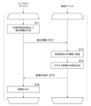
- FIG. 2 is a functional block diagram illustrating an example of a control device according to an embodiment of the present invention. It is a flow chart figure showing an example of operation of a stimulation system concerning an embodiment of the present invention. It is a functional block diagram showing another example of a control device concerning an embodiment of the present invention.
- FIG. 2 is an explanatory diagram showing an example of frequency domain information of detection information detected by the stimulation system according to the embodiment of the present invention.
- a stimulation system 1 includes an implant device 10 that is implanted inside a target body that is an animal including a human, and a control device 20 that is disposed outside the target body. It consists of:
- the implant device 10 includes a transmitting/receiving section 11, a power supply section 12, a stimulation circuit section 13, a sensor section 14, and a processor section 15.
- the control device 20 includes a transmitting/receiving section 21 , a control section 22 , a storage section 23 , a communication section 24 , and a power supply section 25 .
- the transmitting/receiving unit 11 of the implant device 10 transmits data to the control device 20 placed outside the target body according to instructions input from the processor unit 15.
- the transmitting/receiving section 11 also receives data from the control device 20 and outputs it to the processor section 15 .
- widely known transmission and reception methods such as NFC, Wi-Fi, Bluetooth (registered trademark), and RFID wireless communication standards can be used.
- the transmitting/receiving section 11 may receive wireless power supply from the control device 20 and output the supplied power to the power supply section 12 .
- the power supply unit 12 includes a battery B and supplies power to each part of the implant device 10. Further, in one example of the present embodiment, the battery B included in the power supply unit 12 is a secondary battery, and may be charged by receiving power input from the transmitting/receiving unit 11.
- the stimulation circuit unit 13 under the control of the processor unit 15, applies stimulation to the target body via electrodes placed at predetermined sites within the target body (hereinafter referred to as stimulation sites).
- the stimulation site where the electrodes are placed is a site where stimulation of nerves, etc. used in spinal cord stimulation therapy, sacral nerve stimulation therapy, vagus nerve stimulation therapy, deep brain stimulation therapy, etc. can be performed, and it should be given to the subject. Selected depending on the type of stimulus.
- the arrangement of the electrodes of the stimulation circuit section 13 can be a widely known arrangement used in the above-mentioned various stimulation therapies, a detailed explanation will be omitted here.
- the stimulation is, for example, a periodic electric signal or a single pulse signal, and its amplitude, frequency, duration, pulse width, etc. are controlled by the processor section 15, which will be described later.
- the sensor unit 14 detects an electrical signal as a physiological signal of the subject using an electrode placed at a predetermined site within the subject (hereinafter referred to as a detection site).
- physiological signals include membrane potential, nerve action potential, tissue pressure, tissue impedance, temperature, and other biomarker signals within the subject body.
- the selection may be made according to a predetermined rule depending on the type of stimulation to be performed. Further, the stimulation site and the detection site may be different sites, adjacent (relatively close) sites, or the same site.
- the processor section 15 is configured to include a program control device such as a CPU, and a storage device such as a memory, and stores and holds detection information representing temporal changes in the electrical signal detected by the sensor section 14 in a memory or the like. .
- the processor section 15 transmits the detection information stored in the memory to the control device 20 via the transmitter/receiver section 11 at a predetermined timing.
- this processor unit 15 accepts instructions (stimulation instructions) received from the control device 20 via the transmitting/receiving unit 11.
- the processor unit 15 determines the frequency, intensity (amplitude), and pulse width (if the electrical signal is a pulse signal) of the electrical signal as the stimulation to be applied to the target body, as well as the timing and duration of the stimulation. Determine parameters such as time. Then, the processor section 15 controls the stimulation circuit section 13 to apply stimulation with an electrical signal defined by the determined parameters.
- the control device 20 is placed outside the body of a subject, which is an animal including a human. This control device 20 is placed at a position where it can communicate with the implant device 10.
- the transmitting/receiving unit 21 receives the detection information sent out by the implant device 10 and outputs it to the control unit 22. Further, the sending/receiving unit 21 sends the instructed information to the implant device 10 in accordance with an instruction input from the control unit 22. Further, in one example of the present embodiment, the transmitting/receiving section 21 may wirelessly supply power to the implant device 10.
- the control unit 22 is a program control device such as a CPU, and operates according to a program stored in the storage unit 23.
- this control section 22 receives detection information sent from the implant device 10 from the transmitting/receiving section 21. Then, the control unit 22 determines the content of the stimulation to be applied to the target body by the implant device 10 based on the accepted detection information, and sends a stimulation instruction representing the determined stimulation to the implant device 10. Instruct the sending/receiving section 21 to do so. The operation of this control section 22 will be described in detail later.
- the storage unit 23 is a memory device or the like, and stores programs executed by the control unit 22. This program may be provided stored in a computer-readable, non-transitory recording medium, and may be copied to the storage unit 23.
- the storage section 23 also operates as a work memory for the control section 22.
- the communication unit 24 is a network interface that performs data communication via, for example, a wireless LAN or a mobile phone network, and in accordance with instructions input from the control unit 22, sends data to a designated destination via a communication means such as a network. and send the data.
- the communication unit 24 also outputs data received via communication means such as a network to the control unit 22.
- the power supply section 25 supplies power to each section of the control device 20. This power supply unit 25 also supplies power when the transmitter/receiver unit 21 wirelessly supplies power to the implant device 10 .
- control unit 22 executes a program stored in the storage unit 23 to control the receiving unit 221, the stimulus determining unit 222, and the instruction sending unit 223, as illustrated in FIG. Achieve a configuration that functionally includes the following.
- the receiving unit 221 receives detection information sent by the implant device 10, which is a detection result of an electrical signal as a physiological signal of the target body detected by the implant device 10.
- the stimulation determining unit 222 determines the content of the stimulation to be applied to the subject by the implant device 10 based on the detection information accepted by the receiving unit 221.
- the detection information represents a time change in an electrical signal detected by the implant device 10 at a predetermined detection site within the subject's body, that is, it is information in the time domain.
- this information it is not possible to clearly understand changes in responses to stimulation of nerves and the like.
- the stimulus determining unit 222 converts the detection information, which is information in the time domain, into information in the frequency domain.
- the detection information which is information in the time domain
- changes in response to stimulation can be detected relatively easily.
- a widely known method such as FFT (Fast Fourier Transform) can be used for this conversion into frequency domain information.
- a predetermined frequency component for example, a signal of 300 Hz
- the stimulus determining unit 222 outputs information representing the content of the stimulus determined by the method exemplified here to the instruction sending unit 223.
- the instruction sending unit 223 sends a stimulation instruction representing the content of the stimulation determined by the stimulation determining unit 222 to the implant device 10.
- threshold values are determined based on the detection result of an electrical signal as a physiological signal acquired by the implant device 10. It may be.
- an information processing device such as a computer that is communicatively connected to the control device 20 or the implant device 10 is used to inject data into the subject's body within a predetermined period (for example, 24 hours).
- a detection result which is a time change in an electrical signal as a physiological signal of the target body, obtained by the implant device 10 implanted in the target body at predetermined timings (for example, every 30 minutes) is acquired.
- the obtained detection result is converted into information on signal strength for each frequency component using a method such as FFT.
- this information processing device classifies the extracted signal strength information into a plurality of classes through clustering processing.
- a widely known method such as the k-means method can be adopted.
- threshold values ⁇ 1 and ⁇ 2 for classifying each class are obtained, so these threshold values ⁇ 1 and ⁇ 2 are set in the control device 20.
- the implant device 10 that obtains the detection results that are the source of the signals targeted for classification by the clustering process is implanted in a specific object (individual) to which the control device 20 that sets the threshold value is attached. It may be implanted in an individual of the same species as the individual (for example, if the individual is a human, not the individual itself but another human).
- the stimulation to be applied is determined by comparing information on the signal strength for each frequency component with a threshold value, but the control device 20 determines the stimulation to be applied by comparing the information on the signal strength for each frequency component with the threshold value.
- the stimulus to be applied may be determined using the information by referring to the time change in the signal strength information for each frequency component (for example, the magnitude of change in signal strength per unit time).
- the implant device 10 implanted in the human body detects an electrical signal as a physiological signal in the human body using an electrode placed at a detection site, and detects the temporal change of the electrical signal.
- Information is stored (S11).
- the implant device 10 sends the stored detection information to the control device 20 placed outside the human body (S12).
- the control device 20 receives the detection information sent out by the implant device 10, and converts the time change of the electrical signal into information on signal strength for each frequency component using FFT or the like (S13).
- the control device 20 refers to the signal strength information for each frequency component obtained in step S13 and determines the content of the stimulation to be applied according to a predetermined rule (S14). In this determination process, as described above, the control device 20, for example, refers to the strength of the signal F of a predetermined frequency component (as an example, a 300Hz signal), and determines whether the strength of the signal F is (a) It is less than a predetermined first threshold ⁇ 1 (b) It exceeds the first threshold ⁇ 1 and is less than the second threshold ⁇ 2 (however, ⁇ 2> ⁇ 1) (c) The second It is determined whether the threshold value ⁇ 2 is exceeded.
- a predetermined frequency component as an example, a 300Hz signal
- the control device 20 determines that the stimulation to be applied is "no stimulation to be applied”. (b) If the first threshold value ⁇ 1 is exceeded and the second threshold value ⁇ 2 is less than 0.5 mA stimulation”. Further, (c) if the second threshold value ⁇ 2 is exceeded, the control device 20 determines the stimulation to be applied as “stimulation with a frequency of 15 Hz and an amplitude of 1.0 mA”.
- the control device 20 sends an instruction representing the content of the stimulation determined in step S14 to the implant device 10 (S15).
- the implant device 10 receives the instructions received from the control device 20, determines parameters such as the frequency and amplitude of the electrical signal as a stimulus to be given to the human body in which the implant device 10 is implanted, and The current to be passed through the electrode to the stimulation site is controlled so as to apply electrical signal stimulation using the determined parameters (S16).
- the stimulation system 1 of this embodiment repeatedly performs the operations from steps S11 to S16.
- the stimulation to be applied is changed depending on the situation of the target human body, etc., and it becomes possible to apply stimulation according to the situation of the target.
- step S14 of the process shown in the example of FIG. 3 the frequency and amplitude of periodic electrical stimulation are controlled as the form of stimulation to be applied, based on information on signal strength for each frequency component.
- the pulse width of the stimulus to be applied, the timing of applying the stimulus, the duration of the stimulation, etc. may be further determined.
- the aspect of stimulation determined based on the signal strength of each of these frequency components may be determined experimentally.
- a server device communicatively connected to the control device 20 via a network detects detected information or a frequency component obtained based on the detected information.
- the content of the stimulation to be applied may be determined using information on the signal strength for each.
- the processing of this server device may be the same as the processing of the stimulus determining unit 222 described above.
- control device 20 uses the detection information accepted by the acceptance unit 221 or the signal intensity for each frequency component obtained by converting it by FFT or the like, as the process of the stimulus determination unit 222, instead of the above-mentioned process.
- information representing the content of the stimulus to be applied is received from the server device, and is output to the instruction sending unit 223.
- the control device 20 issues a trial stimulation instruction (trial stimulation instruction) representing a plurality of candidate stimuli having different stimulation contents to the implant device 10 at a predetermined timing.
- the effect of the transmitted trial stimulation instruction may be evaluated using the detection information received from the implant device 10 after the trial stimulation instruction is transmitted.
- the control device 20 subjects the evaluation results for each stimulation instruction corresponding to the plurality of candidate stimuli to predetermined processing related to determination of the stimulation instruction.
- control section 22 of the control device 20 includes a receiving section 221, a stimulus determining section 222', an instruction sending section 223, a trial stimulating section 225, and an evaluating section 226, as illustrated in FIG. Realize functional configuration.
- the same reference numerals are used for the same operations as in the example of FIG. 2, and detailed explanation thereof will be omitted.
- the trial stimulation unit 225 sends stimulation instructions representing a plurality of candidate stimulations having mutually different stimulation contents to the implant device 10 at predetermined timings.
- the trial stimulation section 225 trials stimulation using a predetermined stimulation pattern, as illustrated below.
- the trial stimulation section 225 receives a plurality of candidates having different stimulation contents from a personal computer or the like that is communicably connected via the communication section 24 through an operation by a doctor or the like. Accept settings for stimuli and timing for delivering stimulus instructions representing each candidate stimulus.
- the frequencies of periodic electrical stimulation are made to differ from each other as contents of mutually different stimulations.
- the present embodiment is not limited to this, and for example, the amplitude of periodic electrical stimulation, the frequency of the stimulation is At least one of the duration, the pulse width of the stimulation, and the frequency of the stimulation may be made different from each other.
- the stimulation circuit section 13 has a plurality of electrodes (three or more), or when the stimulation circuit section 13 itself is provided with a plurality of electrodes, in other words, when there are multiple stimulation site candidates, which The stimulation sites may be stimulated differently, and as long as mutually different stimulations can be applied to the subject, various modifications can be made to the content.
- the trial stimulation unit 225 outputs, to the implant device 10, (1) a stimulation instruction representing a candidate stimulation of 14 Hz, 1.0 mA, and duration of 10 seconds, according to the accepted settings. and (2) wait 30 seconds. Further, the trial stimulation unit 225 outputs information representing the content of the stimulation instruction output to the implant device 10 to the evaluation unit 226.
- the implant device 10 receives the stimulation instruction from the control device 20, and according to the stimulation instruction, the frequency and amplitude of the electrical signal as the stimulation to be given to the target body, which is the human body in which the implant device 10 is implanted. and other parameters.
- electrical stimulation of 14 Hz, 1.0 mA, and duration of 10 seconds is applied to the stimulation site of the subject's body.
- the implant device 10 detects an electrical signal as a physiological signal within the subject's body using the electrode arranged at the detection site, and expresses the temporal change. Store detection information. The implant device 10 then sends the stored detection information to the control device 20 at a predetermined timing (here, the timing is before the trial stimulation unit 225 outputs the next trial instruction). do. This detection information is processed by the evaluation unit 226, which will be described later.
- the trial stimulation unit 225 After waiting for 30 seconds in (2) above, the trial stimulation unit 225 outputs (3) a stimulation instruction representing a candidate stimulus of 15 Hz, 1.0 mA, and duration of 10 seconds. and (4) wait 30 seconds. Further, the trial stimulation unit 225 outputs information representing the content of the stimulation instruction output to the implant device 10 to the evaluation unit 226.
- the implant device 10 receives the stimulation instruction from the control device 20 and, in accordance with the stimulation instruction, applies electrical stimulation to the stimulation site of the target body at 15 Hz, 1.0 mA, and a duration of 10 seconds. Apply to the stimulation site. Then, while the trial stimulation unit 225 waits for 30 seconds, the implant device 10 detects the electrical signal as a physiological signal within the subject body using the electrode placed at the detection site, and detects the temporal change. Store the detected information represented. The implant device 10 then transmits the stored detection information to the control device 20 at a predetermined timing (here, as described above, the timing is set before the trial stimulation unit 225 outputs the next stimulation instruction). Send to.
- a predetermined timing here, as described above, the timing is set before the trial stimulation unit 225 outputs the next stimulation instruction.
- the trial stimulation section 225 repeats the operation of sending a stimulation instruction representing a candidate stimulation to the implant device 10 according to the settings and waiting for a predetermined period of time.
- the implant device 10 receives a stimulation instruction representing a candidate stimulus, it applies electrical stimulation in accordance with the stimulation instruction to the stimulation site of the target body, and during the subsequent period when the trial stimulation section 225 is on standby.
- Detection information is obtained by detecting an electrical signal as a physiological signal within the subject's body, and then the detection information is sent to the control device 20.
- the operation (and its settings) of the trial stimulation section 225 described in this explanation is just an example, and when another operation is set, the trial stimulation section 225 will perform the operation according to the setting. For example, instead of waiting for a predetermined time as described above, the trial stimulation section 225 may determine the timing for outputting the next stimulation instruction as follows.
- the trial stimulation unit 225 waits after receiving a stimulation instruction, and when the receiving unit 221 receives detection information during this waiting, it starts the next stimulation based on the accepted detection information. Decide whether to output instructions.
- the trial stimulation unit 225 may output a stimulation instruction representing a stimulation candidate to be output next, depending on the settings.
- the trial stimulation unit 225 in this case converts the detection information accepted by the receiving unit 221 into signal strength information for each frequency component (frequency domain information) using FFT or the like.
- the trial stimulation unit 225 may determine to output the stimulation instruction when the intensity of the signal F of a predetermined frequency component (for example, a signal of 300 Hz) exceeds a predetermined threshold value ⁇ .
- This threshold value ⁇ is the same as either the first threshold value ⁇ 1 or the second threshold value ⁇ 2 (where ⁇ 2> ⁇ 1) used by the stimulus determining unit 222 illustrated in FIG. It may be different or it may be different.
- the threshold value used here may also be obtained by clustering processing based on multiple detection information obtained over a predetermined period, as in the example already described.
- the trial stimulation unit 225 waits until the intensity of the signal F of the predetermined frequency component in the frequency domain information obtained by converting the detection information accepted by the receiving unit 221 exceeds the threshold value ⁇ . Then, (1) output a stimulation instruction representing a candidate stimulus of 14 Hz, 1.0 mA, and duration of 10 seconds. Then, after waiting until the intensity of the signal F of the predetermined frequency component in the frequency domain information obtained by converting the detection information accepted by the receiving unit 221 exceeds the threshold value ⁇ again, (3) It operates by outputting a stimulation instruction representing a candidate stimulation of 15 Hz, 1.0 mA, and duration of 10 seconds.
- the trial stimulation unit 225 further performs the following operation instead of waiting for a timing when a set time has elapsed or a timing determined based on the detection information accepted by the receiving unit 221 and outputting a stimulation instruction representing a candidate stimulus.
- a predetermined time has not elapsed since the previous output of a stimulus instruction representing a candidate stimulus at the timing at which the receiving unit 221 determines to output a stimulation instruction representing a candidate stimulus based on the detection information accepted
- the predetermined The timing for outputting a stimulus instruction representing a candidate stimulus is determined based on a combination of the timing at which a set time has elapsed and the timing determined based on the detection information accepted by the receiving unit 221, such as waiting for a period of time. May be controlled.
- the evaluation unit 226 receives the detection information from the implant device 10 after the trial stimulation unit 225 sends out the stimulation instruction, that is, after receiving information representing the content of the stimulation instruction sent out from the trial stimulation unit 225. Then, the evaluation unit 226 evaluates whether or not the stimulation instruction sent by the trial stimulation unit 225 was effective, or the degree of the effect, based on the detected information.
- the evaluation unit 226 converts detection information that is time domain information into frequency domain information using FFT.
- the evaluation unit 226 evaluates the degree of effectiveness of the stimulation instruction sent by the trial stimulation unit 225 based on the intensity of the signal F of a predetermined frequency component (for example, a signal of 300 Hz). For example, the evaluation unit 226 compares the intensities of the signal F of the predetermined frequency component (as an example, a signal of 300 Hz) in the detection information for a plurality of different stimulation instructions sent out by the trial stimulation unit 225, and determines which intensity is the smallest. The stimulation instructions corresponding to the detected information are identified. The evaluation unit 226 determines that the identified stimulation instruction is the most effective stimulation instruction and outputs the content of the corresponding stimulation instruction to the stimulation determination unit 222'.
- a predetermined frequency component for example, a signal of 300 Hz
- the intensity of the signal F of the predetermined frequency component (as an example, a signal of 300 Hz) in the detection information for a plurality of different stimulation instructions sent out by the trial stimulation unit 225 is compared, and the detection information with the lowest intensity is selected.
- the evaluation unit 226 is not limited to this example.
- the most effective stimulation instruction may be determined by examining the temporal change in the intensity of the 300 Hz signal F (for example, by determining the magnitude of the rate of decrease per unit time).
- FIG. 5 shows that, as in the above example, the trial stimulation unit 225 outputs (1) stimulation instructions representing candidate stimulations of 14 Hz, 1.0 mA, and duration of 10 seconds; (3) Output a stimulation instruction representing a candidate stimulus of 15Hz, 1.0mA, and duration of 10 seconds; (5) Output a stimulation instruction representing a candidate stimulus of 16Hz, 1.0mA, and duration of 10 seconds;
- This is an example of frequency-domain information obtained by converting the detected signal obtained after processing by FFT, with the horizontal axis representing the frequency (Hz) and the vertical axis representing the signal intensity (arbitrary unit).
- the detection signal for a candidate stimulus of 14 Hz, 1.0 mA, and duration of 10 seconds is such that the intensity of the signal F of a predetermined frequency component (a signal of 300 Hz as an example) is different from that of other ( b) It is lower than the detection signal for the candidate stimulus of 15 Hz, 1.0 mA, and duration of 10 seconds, and (c) the detection signal for the candidate stimulus of 16 Hz, 1.0 mA, and duration of 10 seconds.
- the evaluation unit 226 determines that the candidate stimulus (a) of 14 Hz, 1.0 mA, and duration of 10 seconds, in which the intensity of the signal F is the lowest, is the most effective candidate stimulus.
- evaluation unit 226 can be realized using widely known processing such as sorting processing, so a more detailed explanation will be omitted here.
- the intensities of the signals F corresponding to the stimulation instructions of the candidate stimulus determined to be the most effective candidate stimulus based on the determination based on the intensities of the signals F corresponding to mutually different stimulation instructions are substantially the same.
- the one with the lower (or higher) frequency or the one with the smaller or larger amplitude (stimulus intensity)
- the determination of which stimulation instruction to select is made, for example, by selecting a stimulation instruction that is considered to have a relatively small load on the target body.
- the stimulus determining unit 222' performs the same operation as the stimulus determining unit 222 described above, and also receives input of information output from the evaluation unit 226 indicating the content of the most effective stimulus instruction, and determines the most effective stimulus instruction. Stores information representing the contents of.
- the stimulus determining unit 222' converts the detection information accepted by the receiving unit 221 into frequency domain information by FFT, similar to the operation of the stimulus determining unit 222 already described, and converts the detection information received by the receiving unit 221 into frequency domain information, and converts the detected information into frequency domain information (for example, As a 300Hz signal) the intensity of F is obtained. Then, for example, when this intensity is less than a predetermined first threshold value ⁇ 1, the stimulus determining unit 222' determines that "there is no stimulus to be applied.” Further, when the intensity of the signal F exceeds the first threshold value ⁇ 1, the stimulus determining section 222' transmits information representing the content of the stimulation based on the content of the stored stimulation instruction to the instruction sending section. 223.
- FFT frequency domain information
- the stimulus determining unit 222' in this example determines the intensity of a signal F of a predetermined frequency component (for example, a signal of 300 Hz) based on the detection information, for example, the intensity of the signal F of a predetermined frequency component obtained by converting the detection information.
- the contents of the memorized stimulation instructions may be corrected. For example, when the intensity of the signal F exceeds the first threshold value ⁇ 1 and is less than the second threshold value ⁇ 2 (however, ⁇ 2> ⁇ 1), the stimulus determining unit 222' Of the content of the stimulation instruction, information representing the amplitude may be corrected, and information representing the content of the stimulation based on the corrected content of the stimulation instruction may be output to the instruction sending unit 223.
- the stimulation determining unit 222' does not correct the content of the stored stimulation instruction.
- information representing the content of stimulation based on the content of the stimulation instruction may be output to the instruction sending unit 223.
- the intensity of the signal F is equal to the first threshold value.
- the stimulation determining unit 222' corrects the contents of the stored stimulation instruction and outputs "14Hz, 0.5mA, continuous. 10 seconds," and outputs information representing the content of stimulation based on the content of the corrected stimulation instruction to the instruction sending unit 223.
- the stimulation determining unit 222' does not correct the content of the stored stimulation instruction. Then, information representing the content of stimulation based on the stored content of the stimulation instruction "14 Hz, 1.0 mA, duration 10 seconds" is output to the instruction sending unit 223.
- the mode of correction described here is an example, and the stimulation determining unit 222' adjusts the amplitude of the periodic electrical stimulation, the duration of the stimulation, the pulse width of the stimulation, and the frequency of the stimulation based on the detection information. At least one may be corrected.
- a server device communicably connected to the control device 20 via the network performs processing equivalent to the stimulus determining section 222' described above, and determines the stimulus to be applied. It is also possible to decide the content.
- control device 20 uses the detection information accepted by the receiving unit 221 or the signal intensity for each frequency component obtained by converting it by FFT etc., as the process of the stimulus determining unit 222′, instead of the above-mentioned process.
- information, and further information representing the content of the most effective stimulation instruction output by the evaluation unit 226, is sent to the server device, information representing the content of the stimulation to be applied is received from the server device, and the instruction is sent to the server device. It is output to the sending unit 223.
- frequency components of detection information (frequency domain information after transformation by FFT etc.) before applying stimulation (pre-stimulation state) are determined through experiments in advance;
- the control device 20 generates a machine learning model that performs machine learning on the content (frequency, amplitude, etc.) of stimulation that has been determined by a doctor to be effective in improving the pre-stimulus condition, and the control device 20 uses this machine learning model Processing using .
- the stimulation determining unit 222 receives the detection information, converts the time change of the electrical signal into information on the signal strength for each frequency component by FFT, etc., and then processes the step S14 illustrated in FIG. 3. In this step, the converted information is input to the machine learning model, and the content of the stimulus to be applied as the output is determined.
- the processing performed by the stimulus determining unit 222 in this example may also be executed in a server device that is communicably connected to the control device 20, as in the example already described.
- the stimulation system 1 of the present embodiment can be used, for example, to suppress overactive bladder (OAB), incontinence, pain management, epilepsy, Alzheimer's disease, and other symptoms. It is available.
- OAB overactive bladder
- Reference Signs List 1 Stimulation system 10 Implant device, 11 Transmission/reception unit, 12 Power supply unit, 13 Stimulation circuit unit, 14 Sensor unit, 15 Processor unit, 20 Control device, 21 Transmission/reception unit, 22 Control unit, 23 Storage unit, 24 Communication unit , 25 power supply section, 221 reception section, 222, 222' stimulus determination section, 223 instruction sending section, 225 trial stimulation section, 226 evaluation section.
Landscapes
- Health & Medical Sciences (AREA)
- Life Sciences & Earth Sciences (AREA)
- Engineering & Computer Science (AREA)
- Animal Behavior & Ethology (AREA)
- Veterinary Medicine (AREA)
- Biomedical Technology (AREA)
- Nuclear Medicine, Radiotherapy & Molecular Imaging (AREA)
- Radiology & Medical Imaging (AREA)
- Public Health (AREA)
- General Health & Medical Sciences (AREA)
- Neurology (AREA)
- Neurosurgery (AREA)
- Physics & Mathematics (AREA)
- Biophysics (AREA)
- Physiology (AREA)
- Acoustics & Sound (AREA)
- Electromagnetism (AREA)
- Electrotherapy Devices (AREA)
Priority Applications (7)
| Application Number | Priority Date | Filing Date | Title |
|---|---|---|---|
| PCT/JP2022/016747 WO2023188347A1 (ja) | 2022-03-31 | 2022-03-31 | 刺激付与システム、インプラントデバイス、制御デバイス、制御デバイスの制御方法、及びプログラム |
| PCT/JP2023/013414 WO2023190999A1 (ja) | 2022-03-31 | 2023-03-30 | 刺激付与システム、インプラントデバイス、制御デバイス、制御デバイスの制御方法、及びプログラム |
| EP23781007.2A EP4501394A4 (en) | 2022-03-31 | 2023-03-30 | STIMULUS APPLICATION SYSTEM, IMPLANT DEVICE, CONTROL DEVICE, CONTROL DEVICE CONTROL METHOD AND PROGRAM |
| CN202380032467.1A CN118984727A (zh) | 2022-03-31 | 2023-03-30 | 刺激施加系统、植入装置、控制器装置、控制控制器装置的方法和程序 |
| US18/851,281 US20250256103A1 (en) | 2022-03-31 | 2023-03-30 | Stimulus application system, implant device, controller device, method for controlling controller device, and program |
| JP2024512866A JP7791603B2 (ja) | 2022-03-31 | 2023-03-30 | 刺激付与システム、インプラントデバイス、制御デバイス、制御デバイスの制御方法、及びプログラム |
| TW112112603A TW202402345A (zh) | 2022-03-31 | 2023-03-31 | 刺激賦予系統、植入裝置、控制裝置、控制裝置之控制方法、及程式 |
Applications Claiming Priority (1)
| Application Number | Priority Date | Filing Date | Title |
|---|---|---|---|
| PCT/JP2022/016747 WO2023188347A1 (ja) | 2022-03-31 | 2022-03-31 | 刺激付与システム、インプラントデバイス、制御デバイス、制御デバイスの制御方法、及びプログラム |
Publications (1)
| Publication Number | Publication Date |
|---|---|
| WO2023188347A1 true WO2023188347A1 (ja) | 2023-10-05 |
Family
ID=88199924
Family Applications (2)
| Application Number | Title | Priority Date | Filing Date |
|---|---|---|---|
| PCT/JP2022/016747 Ceased WO2023188347A1 (ja) | 2022-03-31 | 2022-03-31 | 刺激付与システム、インプラントデバイス、制御デバイス、制御デバイスの制御方法、及びプログラム |
| PCT/JP2023/013414 Ceased WO2023190999A1 (ja) | 2022-03-31 | 2023-03-30 | 刺激付与システム、インプラントデバイス、制御デバイス、制御デバイスの制御方法、及びプログラム |
Family Applications After (1)
| Application Number | Title | Priority Date | Filing Date |
|---|---|---|---|
| PCT/JP2023/013414 Ceased WO2023190999A1 (ja) | 2022-03-31 | 2023-03-30 | 刺激付与システム、インプラントデバイス、制御デバイス、制御デバイスの制御方法、及びプログラム |
Country Status (6)
| Country | Link |
|---|---|
| US (1) | US20250256103A1 (https=) |
| EP (1) | EP4501394A4 (https=) |
| JP (1) | JP7791603B2 (https=) |
| CN (1) | CN118984727A (https=) |
| TW (1) | TW202402345A (https=) |
| WO (2) | WO2023188347A1 (https=) |
Citations (3)
| Publication number | Priority date | Publication date | Assignee | Title |
|---|---|---|---|---|
| US20060020297A1 (en) * | 2004-07-20 | 2006-01-26 | Gerber Martin T | Neurostimulation system with distributed stimulators |
| JP2013527784A (ja) * | 2010-04-27 | 2013-07-04 | メドトロニック,インコーポレイテッド | 刺激電極選択 |
| US20190269924A1 (en) * | 2016-10-28 | 2019-09-05 | Medtronic, Inc. | Autotitration of therapy using detected electrical activity |
Family Cites Families (8)
| Publication number | Priority date | Publication date | Assignee | Title |
|---|---|---|---|---|
| US7418290B2 (en) | 2003-05-06 | 2008-08-26 | Aspect Medical Systems, Inc. | System and method of assessment of the efficacy of treatment of neurological disorders using the electroencephalogram |
| US7983757B2 (en) * | 2007-10-26 | 2011-07-19 | Medtronic, Inc. | Medical device configuration based on sensed brain signals |
| WO2010088533A1 (en) * | 2009-01-30 | 2010-08-05 | Medtronic, Inc. | Closed-loop neurostimulation to treat pulmonary edema |
| US9925379B2 (en) * | 2015-12-22 | 2018-03-27 | Pacesetter, Inc. | System and method for managing stimulation of select A-beta fiber components |
| US11213687B2 (en) | 2016-02-03 | 2022-01-04 | The Charles Stark Draper Laboratory, Inc. | Neural implant for microstimulation |
| WO2017214638A1 (en) | 2016-06-10 | 2017-12-14 | Williams, Jack | System for wireless recording and stimulating of bioelectric events |
| CN113613713B (zh) | 2019-03-06 | 2024-07-19 | 浙江迈达佩思医疗科技有限公司 | 将疗法递送至肠道肌肉的装置、系统和方法 |
| CN111346297B (zh) * | 2020-03-16 | 2021-03-23 | 首都医科大学宣武医院 | 多靶点电刺激电路、电刺激器及其信号输出方法 |
-
2022
- 2022-03-31 WO PCT/JP2022/016747 patent/WO2023188347A1/ja not_active Ceased
-
2023
- 2023-03-30 EP EP23781007.2A patent/EP4501394A4/en active Pending
- 2023-03-30 CN CN202380032467.1A patent/CN118984727A/zh active Pending
- 2023-03-30 JP JP2024512866A patent/JP7791603B2/ja active Active
- 2023-03-30 US US18/851,281 patent/US20250256103A1/en active Pending
- 2023-03-30 WO PCT/JP2023/013414 patent/WO2023190999A1/ja not_active Ceased
- 2023-03-31 TW TW112112603A patent/TW202402345A/zh unknown
Patent Citations (3)
| Publication number | Priority date | Publication date | Assignee | Title |
|---|---|---|---|---|
| US20060020297A1 (en) * | 2004-07-20 | 2006-01-26 | Gerber Martin T | Neurostimulation system with distributed stimulators |
| JP2013527784A (ja) * | 2010-04-27 | 2013-07-04 | メドトロニック,インコーポレイテッド | 刺激電極選択 |
| US20190269924A1 (en) * | 2016-10-28 | 2019-09-05 | Medtronic, Inc. | Autotitration of therapy using detected electrical activity |
Also Published As
| Publication number | Publication date |
|---|---|
| JPWO2023190999A1 (https=) | 2023-10-05 |
| US20250256103A1 (en) | 2025-08-14 |
| CN118984727A (zh) | 2024-11-19 |
| TW202402345A (zh) | 2024-01-16 |
| EP4501394A1 (en) | 2025-02-05 |
| EP4501394A4 (en) | 2026-02-25 |
| JP7791603B2 (ja) | 2025-12-24 |
| WO2023190999A1 (ja) | 2023-10-05 |
Similar Documents
| Publication | Publication Date | Title |
|---|---|---|
| US11338138B2 (en) | Method and system for rapid acquisition of evoked compound action potential recordings | |
| US20250195887A1 (en) | Systems and methods for fitting a hearing system to a recipient based on cortical potentials of the recipient | |
| EP1205089B1 (en) | Apparatus for optimising the operation of a cochlear implant prosthesis | |
| CN108353236B (zh) | 刺激参数优化 | |
| US20130041430A1 (en) | System and method for treating a pelvic condition of a patient | |
| US11534597B2 (en) | Stimulation response profiles | |
| US10512588B2 (en) | Sexual stimulating system and method with feedback control | |
| JP2014523261A (ja) | 神経刺激を制御するための方法および装置 | |
| US20180214700A1 (en) | Stimulation field templates to be applied across patient populations | |
| JP2019509089A (ja) | 代謝および内分泌機能のための末梢神経刺激のシステム | |
| CN113613714A (zh) | 用于神经疗法筛选和/或参数选择的感觉阈值和/或适应性,以及相关系统和方法 | |
| CN112206415B (zh) | 脉冲信号的处理电路、方法及中高频电刺激装置 | |
| CN110402161A (zh) | 用于神经刺激的引线放置 | |
| KR102460537B1 (ko) | 신경 신호 처리 기반의 적응형 신경 자극 시스템, 장치 및 방법 | |
| CN116322896A (zh) | 可再充电的神经调节设备 | |
| WO2023188347A1 (ja) | 刺激付与システム、インプラントデバイス、制御デバイス、制御デバイスの制御方法、及びプログラム | |
| US12415066B2 (en) | Biomimetic stimulator system for neural implant | |
| KR20140141425A (ko) | 배뇨 조절용 자극 정보 제공 장치 | |
| HK40118705A (zh) | 刺激施加系统、植入装置、控制器装置、控制控制器装置的方法和程序 | |
| KR101653225B1 (ko) | 통증치료 장치 및 방법 | |
| WO2020237008A1 (en) | Stimulation response profiles | |
| MXPA04004755A (es) | Dispositivo y metodo para grabar, almacenar y difundir formas de onda especificas para modular el funcionamiento de organos del cuerpo. | |
| KR102842196B1 (ko) | 신경 신호 분석에 기반한 적응형 뇌자극 조절 시스템, 장치 및 방법 | |
| WO2022058829A1 (en) | Parameter optimization based on different degrees of focusing | |
| CN222488604U (zh) | 一种脉冲发生器及神经刺激器 |
Legal Events
| Date | Code | Title | Description |
|---|---|---|---|
| 121 | Ep: the epo has been informed by wipo that ep was designated in this application |
Ref document number: 22935488 Country of ref document: EP Kind code of ref document: A1 |
|
| NENP | Non-entry into the national phase |
Ref country code: DE |
|
| 32PN | Ep: public notification in the ep bulletin as address of the adressee cannot be established |
Free format text: NOTING OF LOSS OF RIGHTS PURSUANT TO RULE 112(1) EPC (EPO FORM 1205A DATED 20.01.2025). |
|
| NENP | Non-entry into the national phase |
Ref country code: JP |
|
| 122 | Ep: pct application non-entry in european phase |
Ref document number: 22935488 Country of ref document: EP Kind code of ref document: A1 |