WO2023188347A1 - Stimulus application system, implant device, control device, method for controlling control device, and program - Google Patents
Stimulus application system, implant device, control device, method for controlling control device, and program Download PDFInfo
- Publication number
- WO2023188347A1 WO2023188347A1 PCT/JP2022/016747 JP2022016747W WO2023188347A1 WO 2023188347 A1 WO2023188347 A1 WO 2023188347A1 JP 2022016747 W JP2022016747 W JP 2022016747W WO 2023188347 A1 WO2023188347 A1 WO 2023188347A1
- Authority
- WO
- WIPO (PCT)
- Prior art keywords
- stimulation
- control device
- implant device
- instruction
- detection information
- Prior art date
Links
- 239000007943 implant Substances 0.000 title claims abstract description 86
- 238000000034 method Methods 0.000 title claims description 21
- 238000001514 detection method Methods 0.000 claims abstract description 89
- 241001465754 Metazoa Species 0.000 claims abstract description 10
- 230000002123 temporal effect Effects 0.000 claims abstract description 9
- 230000000638 stimulation Effects 0.000 claims description 260
- 238000011156 evaluation Methods 0.000 claims description 20
- 230000008859 change Effects 0.000 claims description 16
- 238000012545 processing Methods 0.000 claims description 12
- 230000000737 periodic effect Effects 0.000 claims description 6
- 230000000694 effects Effects 0.000 claims description 4
- 238000004891 communication Methods 0.000 description 9
- 230000008569 process Effects 0.000 description 9
- 238000002560 therapeutic procedure Methods 0.000 description 6
- 238000010801 machine learning Methods 0.000 description 5
- 238000010586 diagram Methods 0.000 description 4
- 230000010365 information processing Effects 0.000 description 4
- 230000005540 biological transmission Effects 0.000 description 3
- 230000007383 nerve stimulation Effects 0.000 description 3
- 241000894007 species Species 0.000 description 3
- 206010020853 Hypertonic bladder Diseases 0.000 description 2
- 208000009722 Overactive Urinary Bladder Diseases 0.000 description 2
- 210000005036 nerve Anatomy 0.000 description 2
- 230000001537 neural effect Effects 0.000 description 2
- 208000020629 overactive bladder Diseases 0.000 description 2
- 230000004044 response Effects 0.000 description 2
- 208000024827 Alzheimer disease Diseases 0.000 description 1
- 241000282412 Homo Species 0.000 description 1
- 206010021639 Incontinence Diseases 0.000 description 1
- 241000282887 Suidae Species 0.000 description 1
- 239000000090 biomarker Substances 0.000 description 1
- 210000004556 brain Anatomy 0.000 description 1
- 238000006243 chemical reaction Methods 0.000 description 1
- 238000012937 correction Methods 0.000 description 1
- 206010015037 epilepsy Diseases 0.000 description 1
- 238000002474 experimental method Methods 0.000 description 1
- 238000007726 management method Methods 0.000 description 1
- 239000012528 membrane Substances 0.000 description 1
- 238000012986 modification Methods 0.000 description 1
- 230000004048 modification Effects 0.000 description 1
- 230000008035 nerve activity Effects 0.000 description 1
- 210000000278 spinal cord Anatomy 0.000 description 1
- 230000004936 stimulating effect Effects 0.000 description 1
- 208000024891 symptom Diseases 0.000 description 1
- 230000009466 transformation Effects 0.000 description 1
- 210000001186 vagus nerve Anatomy 0.000 description 1
Images


Classifications
-
- A—HUMAN NECESSITIES
- A61—MEDICAL OR VETERINARY SCIENCE; HYGIENE
- A61N—ELECTROTHERAPY; MAGNETOTHERAPY; RADIATION THERAPY; ULTRASOUND THERAPY
- A61N1/00—Electrotherapy; Circuits therefor
- A61N1/02—Details
- A61N1/04—Electrodes
- A61N1/05—Electrodes for implantation or insertion into the body, e.g. heart electrode
-
- A—HUMAN NECESSITIES
- A61—MEDICAL OR VETERINARY SCIENCE; HYGIENE
- A61N—ELECTROTHERAPY; MAGNETOTHERAPY; RADIATION THERAPY; ULTRASOUND THERAPY
- A61N1/00—Electrotherapy; Circuits therefor
- A61N1/02—Details
- A61N1/08—Arrangements or circuits for monitoring, protecting, controlling or indicating
-
- A—HUMAN NECESSITIES
- A61—MEDICAL OR VETERINARY SCIENCE; HYGIENE
- A61N—ELECTROTHERAPY; MAGNETOTHERAPY; RADIATION THERAPY; ULTRASOUND THERAPY
- A61N1/00—Electrotherapy; Circuits therefor
- A61N1/18—Applying electric currents by contact electrodes
- A61N1/32—Applying electric currents by contact electrodes alternating or intermittent currents
- A61N1/36—Applying electric currents by contact electrodes alternating or intermittent currents for stimulation
- A61N1/372—Arrangements in connection with the implantation of stimulators
Definitions
- the present invention relates to a stimulation system, an implant device, a control device, a control method for a control device, and a program.
- a neural implant device including a circuit configured to receive an input signal and generate an electrical signal based on the received input signal is disclosed in US Pat.
- the conventional neural implant device described above does not perform control based on physiological signals within the body, so there is a problem in that stimulation is not necessarily given depending on the subject's situation.
- the present invention has been made in view of the above circumstances, and aims to provide a stimulation application system, an implant device, a control device, a control method for the control device, and a program that can provide stimulation according to the situation of the target. This is one of the purposes.
- One aspect of the present invention for solving the above-mentioned problems of the conventional example is an implant device that is implanted into a target body, which is an animal including a human, and is communicably connected to a control device placed outside the target body.
- a detection means for detecting an electrical signal as a physiological signal at a predetermined site within the subject body, and detection information representing a time change of the detected electrical signal are transmitted, and the control device detects the electrical signal as a physiological signal in the subject body.
- a transmitting/receiving means for receiving a stimulation instruction indicating a stimulation to be applied to the target body; and an applying means for applying an electrical stimulation to a predetermined region within the subject body based on the stimulation instruction received by the transmitting/receiving means. That is.
- a control device disposed outside a target body, which is an animal including a human, and which is communicably connected to an implant device.
- the device is implanted in the subject's body to detect an electrical signal as a physiological signal at a predetermined site in the subject's body, and the control device is configured to detect a detection result of the electrical signal sent by the implant device.
- a receiving means for receiving detection information representing the received detection information; a determining means for determining the contents of the stimulation to be applied to the target body by the implant device based on the received detection information; and a stimulation instruction representing the determined stimulation; and a delivery means for delivering the delivery to the implant device.
- FIG. 1 is a configuration block diagram illustrating an example of a stimulation system according to an embodiment of the present invention.
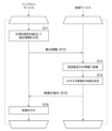
- FIG. 2 is a functional block diagram illustrating an example of a control device according to an embodiment of the present invention. It is a flow chart figure showing an example of operation of a stimulation system concerning an embodiment of the present invention. It is a functional block diagram showing another example of a control device concerning an embodiment of the present invention.
- FIG. 2 is an explanatory diagram showing an example of frequency domain information of detection information detected by the stimulation system according to the embodiment of the present invention.
- a stimulation system 1 includes an implant device 10 that is implanted inside a target body that is an animal including a human, and a control device 20 that is disposed outside the target body. It consists of:
- the implant device 10 includes a transmitting/receiving section 11, a power supply section 12, a stimulation circuit section 13, a sensor section 14, and a processor section 15.
- the control device 20 includes a transmitting/receiving section 21 , a control section 22 , a storage section 23 , a communication section 24 , and a power supply section 25 .
- the transmitting/receiving unit 11 of the implant device 10 transmits data to the control device 20 placed outside the target body according to instructions input from the processor unit 15.
- the transmitting/receiving section 11 also receives data from the control device 20 and outputs it to the processor section 15 .
- widely known transmission and reception methods such as NFC, Wi-Fi, Bluetooth (registered trademark), and RFID wireless communication standards can be used.
- the transmitting/receiving section 11 may receive wireless power supply from the control device 20 and output the supplied power to the power supply section 12 .
- the power supply unit 12 includes a battery B and supplies power to each part of the implant device 10. Further, in one example of the present embodiment, the battery B included in the power supply unit 12 is a secondary battery, and may be charged by receiving power input from the transmitting/receiving unit 11.
- the stimulation circuit unit 13 under the control of the processor unit 15, applies stimulation to the target body via electrodes placed at predetermined sites within the target body (hereinafter referred to as stimulation sites).
- the stimulation site where the electrodes are placed is a site where stimulation of nerves, etc. used in spinal cord stimulation therapy, sacral nerve stimulation therapy, vagus nerve stimulation therapy, deep brain stimulation therapy, etc. can be performed, and it should be given to the subject. Selected depending on the type of stimulus.
- the arrangement of the electrodes of the stimulation circuit section 13 can be a widely known arrangement used in the above-mentioned various stimulation therapies, a detailed explanation will be omitted here.
- the stimulation is, for example, a periodic electric signal or a single pulse signal, and its amplitude, frequency, duration, pulse width, etc. are controlled by the processor section 15, which will be described later.
- the sensor unit 14 detects an electrical signal as a physiological signal of the subject using an electrode placed at a predetermined site within the subject (hereinafter referred to as a detection site).
- physiological signals include membrane potential, nerve action potential, tissue pressure, tissue impedance, temperature, and other biomarker signals within the subject body.
- the selection may be made according to a predetermined rule depending on the type of stimulation to be performed. Further, the stimulation site and the detection site may be different sites, adjacent (relatively close) sites, or the same site.
- the processor section 15 is configured to include a program control device such as a CPU, and a storage device such as a memory, and stores and holds detection information representing temporal changes in the electrical signal detected by the sensor section 14 in a memory or the like. .
- the processor section 15 transmits the detection information stored in the memory to the control device 20 via the transmitter/receiver section 11 at a predetermined timing.
- this processor unit 15 accepts instructions (stimulation instructions) received from the control device 20 via the transmitting/receiving unit 11.
- the processor unit 15 determines the frequency, intensity (amplitude), and pulse width (if the electrical signal is a pulse signal) of the electrical signal as the stimulation to be applied to the target body, as well as the timing and duration of the stimulation. Determine parameters such as time. Then, the processor section 15 controls the stimulation circuit section 13 to apply stimulation with an electrical signal defined by the determined parameters.
- the control device 20 is placed outside the body of a subject, which is an animal including a human. This control device 20 is placed at a position where it can communicate with the implant device 10.
- the transmitting/receiving unit 21 receives the detection information sent out by the implant device 10 and outputs it to the control unit 22. Further, the sending/receiving unit 21 sends the instructed information to the implant device 10 in accordance with an instruction input from the control unit 22. Further, in one example of the present embodiment, the transmitting/receiving section 21 may wirelessly supply power to the implant device 10.
- the control unit 22 is a program control device such as a CPU, and operates according to a program stored in the storage unit 23.
- this control section 22 receives detection information sent from the implant device 10 from the transmitting/receiving section 21. Then, the control unit 22 determines the content of the stimulation to be applied to the target body by the implant device 10 based on the accepted detection information, and sends a stimulation instruction representing the determined stimulation to the implant device 10. Instruct the sending/receiving section 21 to do so. The operation of this control section 22 will be described in detail later.
- the storage unit 23 is a memory device or the like, and stores programs executed by the control unit 22. This program may be provided stored in a computer-readable, non-transitory recording medium, and may be copied to the storage unit 23.
- the storage section 23 also operates as a work memory for the control section 22.
- the communication unit 24 is a network interface that performs data communication via, for example, a wireless LAN or a mobile phone network, and in accordance with instructions input from the control unit 22, sends data to a designated destination via a communication means such as a network. and send the data.
- the communication unit 24 also outputs data received via communication means such as a network to the control unit 22.
- the power supply section 25 supplies power to each section of the control device 20. This power supply unit 25 also supplies power when the transmitter/receiver unit 21 wirelessly supplies power to the implant device 10 .
- control unit 22 executes a program stored in the storage unit 23 to control the receiving unit 221, the stimulus determining unit 222, and the instruction sending unit 223, as illustrated in FIG. Achieve a configuration that functionally includes the following.
- the receiving unit 221 receives detection information sent by the implant device 10, which is a detection result of an electrical signal as a physiological signal of the target body detected by the implant device 10.
- the stimulation determining unit 222 determines the content of the stimulation to be applied to the subject by the implant device 10 based on the detection information accepted by the receiving unit 221.
- the detection information represents a time change in an electrical signal detected by the implant device 10 at a predetermined detection site within the subject's body, that is, it is information in the time domain.
- this information it is not possible to clearly understand changes in responses to stimulation of nerves and the like.
- the stimulus determining unit 222 converts the detection information, which is information in the time domain, into information in the frequency domain.
- the detection information which is information in the time domain
- changes in response to stimulation can be detected relatively easily.
- a widely known method such as FFT (Fast Fourier Transform) can be used for this conversion into frequency domain information.
- a predetermined frequency component for example, a signal of 300 Hz
- the stimulus determining unit 222 outputs information representing the content of the stimulus determined by the method exemplified here to the instruction sending unit 223.
- the instruction sending unit 223 sends a stimulation instruction representing the content of the stimulation determined by the stimulation determining unit 222 to the implant device 10.
- threshold values are determined based on the detection result of an electrical signal as a physiological signal acquired by the implant device 10. It may be.
- an information processing device such as a computer that is communicatively connected to the control device 20 or the implant device 10 is used to inject data into the subject's body within a predetermined period (for example, 24 hours).
- a detection result which is a time change in an electrical signal as a physiological signal of the target body, obtained by the implant device 10 implanted in the target body at predetermined timings (for example, every 30 minutes) is acquired.
- the obtained detection result is converted into information on signal strength for each frequency component using a method such as FFT.
- this information processing device classifies the extracted signal strength information into a plurality of classes through clustering processing.
- a widely known method such as the k-means method can be adopted.
- threshold values ⁇ 1 and ⁇ 2 for classifying each class are obtained, so these threshold values ⁇ 1 and ⁇ 2 are set in the control device 20.
- the implant device 10 that obtains the detection results that are the source of the signals targeted for classification by the clustering process is implanted in a specific object (individual) to which the control device 20 that sets the threshold value is attached. It may be implanted in an individual of the same species as the individual (for example, if the individual is a human, not the individual itself but another human).
- the stimulation to be applied is determined by comparing information on the signal strength for each frequency component with a threshold value, but the control device 20 determines the stimulation to be applied by comparing the information on the signal strength for each frequency component with the threshold value.
- the stimulus to be applied may be determined using the information by referring to the time change in the signal strength information for each frequency component (for example, the magnitude of change in signal strength per unit time).
- the implant device 10 implanted in the human body detects an electrical signal as a physiological signal in the human body using an electrode placed at a detection site, and detects the temporal change of the electrical signal.
- Information is stored (S11).
- the implant device 10 sends the stored detection information to the control device 20 placed outside the human body (S12).
- the control device 20 receives the detection information sent out by the implant device 10, and converts the time change of the electrical signal into information on signal strength for each frequency component using FFT or the like (S13).
- the control device 20 refers to the signal strength information for each frequency component obtained in step S13 and determines the content of the stimulation to be applied according to a predetermined rule (S14). In this determination process, as described above, the control device 20, for example, refers to the strength of the signal F of a predetermined frequency component (as an example, a 300Hz signal), and determines whether the strength of the signal F is (a) It is less than a predetermined first threshold ⁇ 1 (b) It exceeds the first threshold ⁇ 1 and is less than the second threshold ⁇ 2 (however, ⁇ 2> ⁇ 1) (c) The second It is determined whether the threshold value ⁇ 2 is exceeded.
- a predetermined frequency component as an example, a 300Hz signal
- the control device 20 determines that the stimulation to be applied is "no stimulation to be applied”. (b) If the first threshold value ⁇ 1 is exceeded and the second threshold value ⁇ 2 is less than 0.5 mA stimulation”. Further, (c) if the second threshold value ⁇ 2 is exceeded, the control device 20 determines the stimulation to be applied as “stimulation with a frequency of 15 Hz and an amplitude of 1.0 mA”.
- the control device 20 sends an instruction representing the content of the stimulation determined in step S14 to the implant device 10 (S15).
- the implant device 10 receives the instructions received from the control device 20, determines parameters such as the frequency and amplitude of the electrical signal as a stimulus to be given to the human body in which the implant device 10 is implanted, and The current to be passed through the electrode to the stimulation site is controlled so as to apply electrical signal stimulation using the determined parameters (S16).
- the stimulation system 1 of this embodiment repeatedly performs the operations from steps S11 to S16.
- the stimulation to be applied is changed depending on the situation of the target human body, etc., and it becomes possible to apply stimulation according to the situation of the target.
- step S14 of the process shown in the example of FIG. 3 the frequency and amplitude of periodic electrical stimulation are controlled as the form of stimulation to be applied, based on information on signal strength for each frequency component.
- the pulse width of the stimulus to be applied, the timing of applying the stimulus, the duration of the stimulation, etc. may be further determined.
- the aspect of stimulation determined based on the signal strength of each of these frequency components may be determined experimentally.
- a server device communicatively connected to the control device 20 via a network detects detected information or a frequency component obtained based on the detected information.
- the content of the stimulation to be applied may be determined using information on the signal strength for each.
- the processing of this server device may be the same as the processing of the stimulus determining unit 222 described above.
- control device 20 uses the detection information accepted by the acceptance unit 221 or the signal intensity for each frequency component obtained by converting it by FFT or the like, as the process of the stimulus determination unit 222, instead of the above-mentioned process.
- information representing the content of the stimulus to be applied is received from the server device, and is output to the instruction sending unit 223.
- the control device 20 issues a trial stimulation instruction (trial stimulation instruction) representing a plurality of candidate stimuli having different stimulation contents to the implant device 10 at a predetermined timing.
- the effect of the transmitted trial stimulation instruction may be evaluated using the detection information received from the implant device 10 after the trial stimulation instruction is transmitted.
- the control device 20 subjects the evaluation results for each stimulation instruction corresponding to the plurality of candidate stimuli to predetermined processing related to determination of the stimulation instruction.
- control section 22 of the control device 20 includes a receiving section 221, a stimulus determining section 222', an instruction sending section 223, a trial stimulating section 225, and an evaluating section 226, as illustrated in FIG. Realize functional configuration.
- the same reference numerals are used for the same operations as in the example of FIG. 2, and detailed explanation thereof will be omitted.
- the trial stimulation unit 225 sends stimulation instructions representing a plurality of candidate stimulations having mutually different stimulation contents to the implant device 10 at predetermined timings.
- the trial stimulation section 225 trials stimulation using a predetermined stimulation pattern, as illustrated below.
- the trial stimulation section 225 receives a plurality of candidates having different stimulation contents from a personal computer or the like that is communicably connected via the communication section 24 through an operation by a doctor or the like. Accept settings for stimuli and timing for delivering stimulus instructions representing each candidate stimulus.
- the frequencies of periodic electrical stimulation are made to differ from each other as contents of mutually different stimulations.
- the present embodiment is not limited to this, and for example, the amplitude of periodic electrical stimulation, the frequency of the stimulation is At least one of the duration, the pulse width of the stimulation, and the frequency of the stimulation may be made different from each other.
- the stimulation circuit section 13 has a plurality of electrodes (three or more), or when the stimulation circuit section 13 itself is provided with a plurality of electrodes, in other words, when there are multiple stimulation site candidates, which The stimulation sites may be stimulated differently, and as long as mutually different stimulations can be applied to the subject, various modifications can be made to the content.
- the trial stimulation unit 225 outputs, to the implant device 10, (1) a stimulation instruction representing a candidate stimulation of 14 Hz, 1.0 mA, and duration of 10 seconds, according to the accepted settings. and (2) wait 30 seconds. Further, the trial stimulation unit 225 outputs information representing the content of the stimulation instruction output to the implant device 10 to the evaluation unit 226.
- the implant device 10 receives the stimulation instruction from the control device 20, and according to the stimulation instruction, the frequency and amplitude of the electrical signal as the stimulation to be given to the target body, which is the human body in which the implant device 10 is implanted. and other parameters.
- electrical stimulation of 14 Hz, 1.0 mA, and duration of 10 seconds is applied to the stimulation site of the subject's body.
- the implant device 10 detects an electrical signal as a physiological signal within the subject's body using the electrode arranged at the detection site, and expresses the temporal change. Store detection information. The implant device 10 then sends the stored detection information to the control device 20 at a predetermined timing (here, the timing is before the trial stimulation unit 225 outputs the next trial instruction). do. This detection information is processed by the evaluation unit 226, which will be described later.
- the trial stimulation unit 225 After waiting for 30 seconds in (2) above, the trial stimulation unit 225 outputs (3) a stimulation instruction representing a candidate stimulus of 15 Hz, 1.0 mA, and duration of 10 seconds. and (4) wait 30 seconds. Further, the trial stimulation unit 225 outputs information representing the content of the stimulation instruction output to the implant device 10 to the evaluation unit 226.
- the implant device 10 receives the stimulation instruction from the control device 20 and, in accordance with the stimulation instruction, applies electrical stimulation to the stimulation site of the target body at 15 Hz, 1.0 mA, and a duration of 10 seconds. Apply to the stimulation site. Then, while the trial stimulation unit 225 waits for 30 seconds, the implant device 10 detects the electrical signal as a physiological signal within the subject body using the electrode placed at the detection site, and detects the temporal change. Store the detected information represented. The implant device 10 then transmits the stored detection information to the control device 20 at a predetermined timing (here, as described above, the timing is set before the trial stimulation unit 225 outputs the next stimulation instruction). Send to.
- a predetermined timing here, as described above, the timing is set before the trial stimulation unit 225 outputs the next stimulation instruction.
- the trial stimulation section 225 repeats the operation of sending a stimulation instruction representing a candidate stimulation to the implant device 10 according to the settings and waiting for a predetermined period of time.
- the implant device 10 receives a stimulation instruction representing a candidate stimulus, it applies electrical stimulation in accordance with the stimulation instruction to the stimulation site of the target body, and during the subsequent period when the trial stimulation section 225 is on standby.
- Detection information is obtained by detecting an electrical signal as a physiological signal within the subject's body, and then the detection information is sent to the control device 20.
- the operation (and its settings) of the trial stimulation section 225 described in this explanation is just an example, and when another operation is set, the trial stimulation section 225 will perform the operation according to the setting. For example, instead of waiting for a predetermined time as described above, the trial stimulation section 225 may determine the timing for outputting the next stimulation instruction as follows.
- the trial stimulation unit 225 waits after receiving a stimulation instruction, and when the receiving unit 221 receives detection information during this waiting, it starts the next stimulation based on the accepted detection information. Decide whether to output instructions.
- the trial stimulation unit 225 may output a stimulation instruction representing a stimulation candidate to be output next, depending on the settings.
- the trial stimulation unit 225 in this case converts the detection information accepted by the receiving unit 221 into signal strength information for each frequency component (frequency domain information) using FFT or the like.
- the trial stimulation unit 225 may determine to output the stimulation instruction when the intensity of the signal F of a predetermined frequency component (for example, a signal of 300 Hz) exceeds a predetermined threshold value ⁇ .
- This threshold value ⁇ is the same as either the first threshold value ⁇ 1 or the second threshold value ⁇ 2 (where ⁇ 2> ⁇ 1) used by the stimulus determining unit 222 illustrated in FIG. It may be different or it may be different.
- the threshold value used here may also be obtained by clustering processing based on multiple detection information obtained over a predetermined period, as in the example already described.
- the trial stimulation unit 225 waits until the intensity of the signal F of the predetermined frequency component in the frequency domain information obtained by converting the detection information accepted by the receiving unit 221 exceeds the threshold value ⁇ . Then, (1) output a stimulation instruction representing a candidate stimulus of 14 Hz, 1.0 mA, and duration of 10 seconds. Then, after waiting until the intensity of the signal F of the predetermined frequency component in the frequency domain information obtained by converting the detection information accepted by the receiving unit 221 exceeds the threshold value ⁇ again, (3) It operates by outputting a stimulation instruction representing a candidate stimulation of 15 Hz, 1.0 mA, and duration of 10 seconds.
- the trial stimulation unit 225 further performs the following operation instead of waiting for a timing when a set time has elapsed or a timing determined based on the detection information accepted by the receiving unit 221 and outputting a stimulation instruction representing a candidate stimulus.
- a predetermined time has not elapsed since the previous output of a stimulus instruction representing a candidate stimulus at the timing at which the receiving unit 221 determines to output a stimulation instruction representing a candidate stimulus based on the detection information accepted
- the predetermined The timing for outputting a stimulus instruction representing a candidate stimulus is determined based on a combination of the timing at which a set time has elapsed and the timing determined based on the detection information accepted by the receiving unit 221, such as waiting for a period of time. May be controlled.
- the evaluation unit 226 receives the detection information from the implant device 10 after the trial stimulation unit 225 sends out the stimulation instruction, that is, after receiving information representing the content of the stimulation instruction sent out from the trial stimulation unit 225. Then, the evaluation unit 226 evaluates whether or not the stimulation instruction sent by the trial stimulation unit 225 was effective, or the degree of the effect, based on the detected information.
- the evaluation unit 226 converts detection information that is time domain information into frequency domain information using FFT.
- the evaluation unit 226 evaluates the degree of effectiveness of the stimulation instruction sent by the trial stimulation unit 225 based on the intensity of the signal F of a predetermined frequency component (for example, a signal of 300 Hz). For example, the evaluation unit 226 compares the intensities of the signal F of the predetermined frequency component (as an example, a signal of 300 Hz) in the detection information for a plurality of different stimulation instructions sent out by the trial stimulation unit 225, and determines which intensity is the smallest. The stimulation instructions corresponding to the detected information are identified. The evaluation unit 226 determines that the identified stimulation instruction is the most effective stimulation instruction and outputs the content of the corresponding stimulation instruction to the stimulation determination unit 222'.
- a predetermined frequency component for example, a signal of 300 Hz
- the intensity of the signal F of the predetermined frequency component (as an example, a signal of 300 Hz) in the detection information for a plurality of different stimulation instructions sent out by the trial stimulation unit 225 is compared, and the detection information with the lowest intensity is selected.
- the evaluation unit 226 is not limited to this example.
- the most effective stimulation instruction may be determined by examining the temporal change in the intensity of the 300 Hz signal F (for example, by determining the magnitude of the rate of decrease per unit time).
- FIG. 5 shows that, as in the above example, the trial stimulation unit 225 outputs (1) stimulation instructions representing candidate stimulations of 14 Hz, 1.0 mA, and duration of 10 seconds; (3) Output a stimulation instruction representing a candidate stimulus of 15Hz, 1.0mA, and duration of 10 seconds; (5) Output a stimulation instruction representing a candidate stimulus of 16Hz, 1.0mA, and duration of 10 seconds;
- This is an example of frequency-domain information obtained by converting the detected signal obtained after processing by FFT, with the horizontal axis representing the frequency (Hz) and the vertical axis representing the signal intensity (arbitrary unit).
- the detection signal for a candidate stimulus of 14 Hz, 1.0 mA, and duration of 10 seconds is such that the intensity of the signal F of a predetermined frequency component (a signal of 300 Hz as an example) is different from that of other ( b) It is lower than the detection signal for the candidate stimulus of 15 Hz, 1.0 mA, and duration of 10 seconds, and (c) the detection signal for the candidate stimulus of 16 Hz, 1.0 mA, and duration of 10 seconds.
- the evaluation unit 226 determines that the candidate stimulus (a) of 14 Hz, 1.0 mA, and duration of 10 seconds, in which the intensity of the signal F is the lowest, is the most effective candidate stimulus.
- evaluation unit 226 can be realized using widely known processing such as sorting processing, so a more detailed explanation will be omitted here.
- the intensities of the signals F corresponding to the stimulation instructions of the candidate stimulus determined to be the most effective candidate stimulus based on the determination based on the intensities of the signals F corresponding to mutually different stimulation instructions are substantially the same.
- the one with the lower (or higher) frequency or the one with the smaller or larger amplitude (stimulus intensity)
- the determination of which stimulation instruction to select is made, for example, by selecting a stimulation instruction that is considered to have a relatively small load on the target body.
- the stimulus determining unit 222' performs the same operation as the stimulus determining unit 222 described above, and also receives input of information output from the evaluation unit 226 indicating the content of the most effective stimulus instruction, and determines the most effective stimulus instruction. Stores information representing the contents of.
- the stimulus determining unit 222' converts the detection information accepted by the receiving unit 221 into frequency domain information by FFT, similar to the operation of the stimulus determining unit 222 already described, and converts the detection information received by the receiving unit 221 into frequency domain information, and converts the detected information into frequency domain information (for example, As a 300Hz signal) the intensity of F is obtained. Then, for example, when this intensity is less than a predetermined first threshold value ⁇ 1, the stimulus determining unit 222' determines that "there is no stimulus to be applied.” Further, when the intensity of the signal F exceeds the first threshold value ⁇ 1, the stimulus determining section 222' transmits information representing the content of the stimulation based on the content of the stored stimulation instruction to the instruction sending section. 223.
- FFT frequency domain information
- the stimulus determining unit 222' in this example determines the intensity of a signal F of a predetermined frequency component (for example, a signal of 300 Hz) based on the detection information, for example, the intensity of the signal F of a predetermined frequency component obtained by converting the detection information.
- the contents of the memorized stimulation instructions may be corrected. For example, when the intensity of the signal F exceeds the first threshold value ⁇ 1 and is less than the second threshold value ⁇ 2 (however, ⁇ 2> ⁇ 1), the stimulus determining unit 222' Of the content of the stimulation instruction, information representing the amplitude may be corrected, and information representing the content of the stimulation based on the corrected content of the stimulation instruction may be output to the instruction sending unit 223.
- the stimulation determining unit 222' does not correct the content of the stored stimulation instruction.
- information representing the content of stimulation based on the content of the stimulation instruction may be output to the instruction sending unit 223.
- the intensity of the signal F is equal to the first threshold value.
- the stimulation determining unit 222' corrects the contents of the stored stimulation instruction and outputs "14Hz, 0.5mA, continuous. 10 seconds," and outputs information representing the content of stimulation based on the content of the corrected stimulation instruction to the instruction sending unit 223.
- the stimulation determining unit 222' does not correct the content of the stored stimulation instruction. Then, information representing the content of stimulation based on the stored content of the stimulation instruction "14 Hz, 1.0 mA, duration 10 seconds" is output to the instruction sending unit 223.
- the mode of correction described here is an example, and the stimulation determining unit 222' adjusts the amplitude of the periodic electrical stimulation, the duration of the stimulation, the pulse width of the stimulation, and the frequency of the stimulation based on the detection information. At least one may be corrected.
- a server device communicably connected to the control device 20 via the network performs processing equivalent to the stimulus determining section 222' described above, and determines the stimulus to be applied. It is also possible to decide the content.
- control device 20 uses the detection information accepted by the receiving unit 221 or the signal intensity for each frequency component obtained by converting it by FFT etc., as the process of the stimulus determining unit 222′, instead of the above-mentioned process.
- information, and further information representing the content of the most effective stimulation instruction output by the evaluation unit 226, is sent to the server device, information representing the content of the stimulation to be applied is received from the server device, and the instruction is sent to the server device. It is output to the sending unit 223.
- frequency components of detection information (frequency domain information after transformation by FFT etc.) before applying stimulation (pre-stimulation state) are determined through experiments in advance;
- the control device 20 generates a machine learning model that performs machine learning on the content (frequency, amplitude, etc.) of stimulation that has been determined by a doctor to be effective in improving the pre-stimulus condition, and the control device 20 uses this machine learning model Processing using .
- the stimulation determining unit 222 receives the detection information, converts the time change of the electrical signal into information on the signal strength for each frequency component by FFT, etc., and then processes the step S14 illustrated in FIG. 3. In this step, the converted information is input to the machine learning model, and the content of the stimulus to be applied as the output is determined.
- the processing performed by the stimulus determining unit 222 in this example may also be executed in a server device that is communicably connected to the control device 20, as in the example already described.
- the stimulation system 1 of the present embodiment can be used, for example, to suppress overactive bladder (OAB), incontinence, pain management, epilepsy, Alzheimer's disease, and other symptoms. It is available.
- OAB overactive bladder
- Reference Signs List 1 Stimulation system 10 Implant device, 11 Transmission/reception unit, 12 Power supply unit, 13 Stimulation circuit unit, 14 Sensor unit, 15 Processor unit, 20 Control device, 21 Transmission/reception unit, 22 Control unit, 23 Storage unit, 24 Communication unit , 25 power supply section, 221 reception section, 222, 222' stimulus determination section, 223 instruction sending section, 225 trial stimulation section, 226 evaluation section.
Abstract
The present invention has an implant device 10 that is embedded in the body of an animal subject including a human and that is communicably connected to a control device 20 that is disposed outside the body of said subject. The implant device 10 involves detecting an electrical signal as a physiological signal at a prescribed site within the subject's body, transmitting detection information indicative of temporal changes of said electrical signal, receiving, from the control device 20, a stimulus instruction indicative of a stimulus to be applied to the subject's body, and applying an electrical stimulus to the prescribed site within the subject's body in accordance with said stimulus instruction.
Description
本発明は、刺激付与システム、インプラントデバイス、制御デバイス、制御デバイスの制御方法、及びプログラムに関する。
The present invention relates to a stimulation system, an implant device, a control device, a control method for a control device, and a program.
入力信号を受信して、受信した入力信号に基づいて電気信号を発生させるように構成された回路を含む神経インプラントデバイスが特許文献1に開示されている。
A neural implant device including a circuit configured to receive an input signal and generate an electrical signal based on the received input signal is disclosed in US Pat.
しかしながら、上記従来の神経インプラントデバイスでは、体内の生理的信号に基づく制御が行われないため、対象者の状況に応じた刺激が与えられるとは限らないという問題点があった。
However, the conventional neural implant device described above does not perform control based on physiological signals within the body, so there is a problem in that stimulation is not necessarily given depending on the subject's situation.
本発明は上記実情に鑑みて為されたもので、対象の状況に応じた刺激を与えることのできる刺激付与システム、インプラントデバイス、制御デバイス、制御デバイスの制御方法、及びプログラムを提供することを、その目的の一つとする。
The present invention has been made in view of the above circumstances, and aims to provide a stimulation application system, an implant device, a control device, a control method for the control device, and a program that can provide stimulation according to the situation of the target. This is one of the purposes.
上記従来例の問題点を解決するための本発明の一態様は、ヒトを含む動物である対象体内に埋め込まれ、当該対象体外に配される制御デバイスと通信可能に接続されるインプラントデバイスであって、前記対象体内の所定の部位における生理的信号としての電気的信号を検出する検出手段と、当該検出した電気的信号の時間変化を表す検出情報を送出し、前記制御デバイスから、前記対象体に付与するべき刺激を表す刺激指示を受信する送受信手段と、前記送受信手段が受信した刺激指示に基づき、前記対象体内の所定の部位に対して電気的刺激を付与する付与手段と、を有することとしたものである。
One aspect of the present invention for solving the above-mentioned problems of the conventional example is an implant device that is implanted into a target body, which is an animal including a human, and is communicably connected to a control device placed outside the target body. A detection means for detecting an electrical signal as a physiological signal at a predetermined site within the subject body, and detection information representing a time change of the detected electrical signal are transmitted, and the control device detects the electrical signal as a physiological signal in the subject body. a transmitting/receiving means for receiving a stimulation instruction indicating a stimulation to be applied to the target body; and an applying means for applying an electrical stimulation to a predetermined region within the subject body based on the stimulation instruction received by the transmitting/receiving means. That is.
また、上記従来例の問題点を解決するための本発明の別の側面は、ヒトを含む動物である対象体外に配される制御デバイスであって、インプラントデバイスと通信可能に接続され、当該インプラントデバイスは、前記対象体内に埋め込まれて、当該対象体内の所定の部位における生理的信号としての電気的信号を検出し、前記制御デバイスは、前記インプラントデバイスが送出する、前記電気的信号の検出結果を表す検出情報を受信する受信手段と、前記受信した検出情報に基づいて、前記インプラントデバイスにより対象体に付与するべき刺激の内容を決定する決定手段と、前記決定した刺激を表す刺激指示を、前記インプラントデバイスに対して送出する送出手段と、を含むこととしたものである。
Another aspect of the present invention for solving the above-mentioned problems of the prior art is a control device disposed outside a target body, which is an animal including a human, and which is communicably connected to an implant device. The device is implanted in the subject's body to detect an electrical signal as a physiological signal at a predetermined site in the subject's body, and the control device is configured to detect a detection result of the electrical signal sent by the implant device. a receiving means for receiving detection information representing the received detection information; a determining means for determining the contents of the stimulation to be applied to the target body by the implant device based on the received detection information; and a stimulation instruction representing the determined stimulation; and a delivery means for delivering the delivery to the implant device.
本発明によると、対象の状況に応じた刺激を与えることが可能となる。
According to the present invention, it is possible to provide stimulation according to the situation of the target.
本発明の実施の形態について図面を参照しながら説明する。本発明の実施の形態に係る刺激付与システム1は、図1に例示するように、ヒトを含む動物である対象体内に埋め込まれるインプラントデバイス10と、当該対象体外に配される制御デバイス20と、を含んで構成される。
Embodiments of the present invention will be described with reference to the drawings. As illustrated in FIG. 1, a stimulation system 1 according to an embodiment of the present invention includes an implant device 10 that is implanted inside a target body that is an animal including a human, and a control device 20 that is disposed outside the target body. It consists of:
ここでインプラントデバイス10は、送受部11と、電源供給部12と、刺激回路部13と、センサ部14と、プロセッサ部15とを含んで構成される。また制御デバイス20は、送受部21と、制御部22と、記憶部23と、通信部24と、電源部25とを含んで構成される。
Here, the implant device 10 includes a transmitting/receiving section 11, a power supply section 12, a stimulation circuit section 13, a sensor section 14, and a processor section 15. Further, the control device 20 includes a transmitting/receiving section 21 , a control section 22 , a storage section 23 , a communication section 24 , and a power supply section 25 .
インプラントデバイス10の送受部11は、プロセッサ部15から入力される指示により、対象体外に配された制御デバイス20に対してデータを送出する。またこの送受部11は、制御デバイス20から受信されるデータを受信して、プロセッサ部15に出力する。ここでのデータは、例えばNFC、Wi-Fi、ブルートゥース(登録商標)、RFID無線通信標準などで広く知られた送受信方法を採用できる。さらに本実施の形態の一例では、この送受部11は、制御デバイス20から電力の無線給電を受けて、当該給電された電力を電源供給部12に出力することとしてもよい。
The transmitting/receiving unit 11 of the implant device 10 transmits data to the control device 20 placed outside the target body according to instructions input from the processor unit 15. The transmitting/receiving section 11 also receives data from the control device 20 and outputs it to the processor section 15 . For the data here, widely known transmission and reception methods such as NFC, Wi-Fi, Bluetooth (registered trademark), and RFID wireless communication standards can be used. Further, in one example of the present embodiment, the transmitting/receiving section 11 may receive wireless power supply from the control device 20 and output the supplied power to the power supply section 12 .
電源供給部12は、電池Bを備え、インプラントデバイス10の各部に電力を供給する。また本実施の形態の一例では、この電源供給部12が備える電池Bは二次電池であり、送受部11から入力される電力を受け入れて、電池Bを充電してもよい。
The power supply unit 12 includes a battery B and supplies power to each part of the implant device 10. Further, in one example of the present embodiment, the battery B included in the power supply unit 12 is a secondary battery, and may be charged by receiving power input from the transmitting/receiving unit 11.
刺激回路部13は、プロセッサ部15からの制御を受けて、対象体内の所定の部位(以下、刺激部位と呼ぶ)に配した電極を介して対象体に刺激を与える。ここで電極を配する刺激部位は、脊髄刺激療法,仙骨神経刺激療法,迷走神経刺激療法,脳深部刺激療法等で用いられる神経等への刺激を行い得る部位であり、対象者に付与するべき刺激の種類によって選択される。このような刺激回路部13の電極の配置は、上記の各種刺激療法で利用されるものとして広く知られた配置を採用できるので、ここでの詳しい説明を省略する。また刺激は例えば周期的な電気信号や単発のパルス信号等であり、その振幅や周波数、継続時間やパルスの幅などは、後に説明するプロセッサ部15から制御される。
The stimulation circuit unit 13, under the control of the processor unit 15, applies stimulation to the target body via electrodes placed at predetermined sites within the target body (hereinafter referred to as stimulation sites). The stimulation site where the electrodes are placed is a site where stimulation of nerves, etc. used in spinal cord stimulation therapy, sacral nerve stimulation therapy, vagus nerve stimulation therapy, deep brain stimulation therapy, etc. can be performed, and it should be given to the subject. Selected depending on the type of stimulus. As the arrangement of the electrodes of the stimulation circuit section 13 can be a widely known arrangement used in the above-mentioned various stimulation therapies, a detailed explanation will be omitted here. Further, the stimulation is, for example, a periodic electric signal or a single pulse signal, and its amplitude, frequency, duration, pulse width, etc. are controlled by the processor section 15, which will be described later.
センサ部14は、対象体内の所定の部位(以下、検出部位と呼ぶ)に配された電極により対象体の生理的信号として電気的信号を検出する。ここで生理的信号は、対象体内の膜電位や、神経電位(Nerve action potential)、組織圧力(Organ pressure)、組織のインピーダンス(Tissue impedance)、温度、その他のバイオマーカーとなる信号であり、付与するべき刺激の種類により予め定めた規則に従って選択すればよい。また刺激部位と検出部位とは異なる部位であってもよいし、隣接した(比較的近接した)部位、ないし、同じ部位であっても構わない。
The sensor unit 14 detects an electrical signal as a physiological signal of the subject using an electrode placed at a predetermined site within the subject (hereinafter referred to as a detection site). Here, physiological signals include membrane potential, nerve action potential, tissue pressure, tissue impedance, temperature, and other biomarker signals within the subject body. The selection may be made according to a predetermined rule depending on the type of stimulation to be performed. Further, the stimulation site and the detection site may be different sites, adjacent (relatively close) sites, or the same site.
プロセッサ部15は、CPUなどのプログラム制御デバイスと、メモリなどの記憶デバイスを含んで構成され、センサ部14が検出した電気的信号の時間変化を表す検出情報を、メモリ等に格納して保持する。プロセッサ部15は、所定のタイミングで、メモリに格納した検出情報を、送受部11を介して制御デバイス20へ送出する。
The processor section 15 is configured to include a program control device such as a CPU, and a storage device such as a memory, and stores and holds detection information representing temporal changes in the electrical signal detected by the sensor section 14 in a memory or the like. . The processor section 15 transmits the detection information stored in the memory to the control device 20 via the transmitter/receiver section 11 at a predetermined timing.
また、このプロセッサ部15は、送受部11を介して制御デバイス20から受信した指示(刺激指示)を受け入れる。プロセッサ部15は、この刺激指示に従い、対象体に与えるべき刺激としての電気信号の周波数や強度(振幅)、パルス幅(電気信号がパルス信号である場合)、さらには、刺激を与えるタイミングや継続時間などのパラメータを決定する。そしてプロセッサ部15は、当該決定したパラメータで規定される電気信号の刺激を付与するよう、刺激回路部13を制御する。
Additionally, this processor unit 15 accepts instructions (stimulation instructions) received from the control device 20 via the transmitting/receiving unit 11. In accordance with this stimulation instruction, the processor unit 15 determines the frequency, intensity (amplitude), and pulse width (if the electrical signal is a pulse signal) of the electrical signal as the stimulation to be applied to the target body, as well as the timing and duration of the stimulation. Determine parameters such as time. Then, the processor section 15 controls the stimulation circuit section 13 to apply stimulation with an electrical signal defined by the determined parameters.
制御デバイス20は、ヒトを含む動物である対象体の体外に配される。この制御デバイス20は、インプラントデバイス10との間で通信可能な位置に配置される。
The control device 20 is placed outside the body of a subject, which is an animal including a human. This control device 20 is placed at a position where it can communicate with the implant device 10.
送受部21は、インプラントデバイス10が送出した検出情報を受信して、制御部22に出力する。またこの送受部21は、制御部22から入力される指示に従い、指示された情報を、インプラントデバイス10へ送出する。さらに本実施の形態の一例では、この送受部21は、インプラントデバイス10に対して無線にて給電を行ってもよい。
The transmitting/receiving unit 21 receives the detection information sent out by the implant device 10 and outputs it to the control unit 22. Further, the sending/receiving unit 21 sends the instructed information to the implant device 10 in accordance with an instruction input from the control unit 22. Further, in one example of the present embodiment, the transmitting/receiving section 21 may wirelessly supply power to the implant device 10.
制御部22は、CPUなどのプログラム制御デバイスであり、記憶部23に格納されたプログラムに従って動作する。本実施の形態の例では、この制御部22は、送受部21からインプラントデバイス10が送出した検出情報を受け入れる。そして制御部22は、当該受け入れた検出情報に基づいて、インプラントデバイス10により対象体に付与するべき刺激の内容を決定し、当該決定した刺激を表す刺激指示を、インプラントデバイス10に対して送出するよう送受部21に指示する。この制御部22の動作については後に詳しく述べる。
The control unit 22 is a program control device such as a CPU, and operates according to a program stored in the storage unit 23. In the example of this embodiment, this control section 22 receives detection information sent from the implant device 10 from the transmitting/receiving section 21. Then, the control unit 22 determines the content of the stimulation to be applied to the target body by the implant device 10 based on the accepted detection information, and sends a stimulation instruction representing the determined stimulation to the implant device 10. Instruct the sending/receiving section 21 to do so. The operation of this control section 22 will be described in detail later.
記憶部23は、メモリデバイス等であり、制御部22によって実行されるプログラムを格納している。このプログラムは、コンピュータ可読かつ非一時的な記録媒体に格納されて提供され、この記憶部23に複写されたものであってもよい。またこの記憶部23は、制御部22のワークメモリとしても動作する。
The storage unit 23 is a memory device or the like, and stores programs executed by the control unit 22. This program may be provided stored in a computer-readable, non-transitory recording medium, and may be copied to the storage unit 23. The storage section 23 also operates as a work memory for the control section 22.
通信部24は、例えば無線LANや携帯電話網を介したデータ通信を行うネットワークインタフェースであり、制御部22から入力される指示に従って、ネットワーク等の通信手段を介して、指示された宛て先に対してデータを送出する。またこの通信部24は、ネットワーク等の通信手段を介して受信されるデータを制御部22に出力する。
The communication unit 24 is a network interface that performs data communication via, for example, a wireless LAN or a mobile phone network, and in accordance with instructions input from the control unit 22, sends data to a designated destination via a communication means such as a network. and send the data. The communication unit 24 also outputs data received via communication means such as a network to the control unit 22.
電源部25は、制御デバイス20の各部に電源を供給する。この電源部25は、また、送受部21がインプラントデバイス10に対して無線にて給電を行う際には、その給電電力を供給する。
The power supply section 25 supplies power to each section of the control device 20. This power supply unit 25 also supplies power when the transmitter/receiver unit 21 wirelessly supplies power to the implant device 10 .
次に、制御デバイス20の制御部22の動作例について説明する。本実施の形態の一例では、この制御部22は、記憶部23に格納されたプログラムを実行することで、図2に例示するように、受入部221、刺激決定部222、及び指示送出部223を機能的に含む構成を実現する。
Next, an example of the operation of the control section 22 of the control device 20 will be described. In one example of the present embodiment, the control unit 22 executes a program stored in the storage unit 23 to control the receiving unit 221, the stimulus determining unit 222, and the instruction sending unit 223, as illustrated in FIG. Achieve a configuration that functionally includes the following.
受入部221は、インプラントデバイス10が送出する、インプラントデバイス10にて検出した対象体の生理的信号としての電気的信号の検出結果である検出情報を受け入れる。
The receiving unit 221 receives detection information sent by the implant device 10, which is a detection result of an electrical signal as a physiological signal of the target body detected by the implant device 10.
刺激決定部222は、受入部221が受け入れた検出情報に基づいて、インプラントデバイス10により対象体に付与するべき刺激の内容を決定する。ここで検出情報は、上述のように、インプラントデバイス10が検出した、対象体内の所定の検出部位における電気的信号の時間変化を表すものであり、つまり、時間領域の情報である。しかしながらこの情報では、神経などの刺激に対する応答の変化を明瞭に把握できない。
The stimulation determining unit 222 determines the content of the stimulation to be applied to the subject by the implant device 10 based on the detection information accepted by the receiving unit 221. Here, as described above, the detection information represents a time change in an electrical signal detected by the implant device 10 at a predetermined detection site within the subject's body, that is, it is information in the time domain. However, with this information, it is not possible to clearly understand changes in responses to stimulation of nerves and the like.
そこで一例として、この刺激決定部222は、この時間領域の情報である検出情報を、周波数領域の情報に変換する。周波数領域の情報とすることで、刺激に対する応答の変化が比較的容易に検出可能となる。この周波数領域の情報への変換には、FFT(Fast Fourier Transform)などの広く知られた方法を採用できる。
As an example, the stimulus determining unit 222 converts the detection information, which is information in the time domain, into information in the frequency domain. By using frequency domain information, changes in response to stimulation can be detected relatively easily. A widely known method such as FFT (Fast Fourier Transform) can be used for this conversion into frequency domain information.
すなわち刺激決定部222は、FFT等により、電気的信号の時間変化を、周波数成分ごとの信号強度の情報に変換する。そして刺激決定部222は、例えば所定の周波数成分の信号(一例として300Hzの信号)Fの強度が、予め定めた第1のしきい値θ1未満であるときに「付与するべき刺激なし」と決定する。また上記信号Fの強度が、上記第1のしきい値θ1を超え、第2のしきい値θ2(ただしθ2>θ1)未満であるときに、刺激決定部222は、「周波数f1の比較的弱い刺激(振幅を0.5mAとするなど)を付与する」と決定する(例えばf1=14Hzなどとして予め定めておく)。
In other words, the stimulus determining unit 222 converts the temporal change in the electrical signal into information on signal strength for each frequency component using FFT or the like. Then, the stimulus determining unit 222 determines that "there is no stimulus to be applied" when the intensity of the signal F of a predetermined frequency component (for example, a signal of 300 Hz) is less than a predetermined first threshold value θ1. do. Further, when the intensity of the signal F exceeds the first threshold value θ1 and is less than the second threshold value θ2 (however, θ2>θ1), the stimulus determining unit 222 A weak stimulus (amplitude of 0.5 mA, etc.) is applied (predetermined in advance as, for example, f1=14 Hz).
さらに、上記信号Fの強度が、上記第2のしきい値θ2を超えるときには、刺激決定部222は、「周波数f2の比較的強い刺激(振幅を1.0mAとするなど)を付与する」と決定する(ここでも例えばf2=15Hzなどとして予め定めておく)。
Further, when the intensity of the signal F exceeds the second threshold value θ2, the stimulus determining unit 222 determines that "a relatively strong stimulus with a frequency f2 (such as an amplitude of 1.0 mA) is applied." (Here also, it is predetermined as, for example, f2=15Hz).
刺激決定部222は、ここで例示した方法で決定した刺激の内容を表す情報を、指示送出部223に出力する。
The stimulus determining unit 222 outputs information representing the content of the stimulus determined by the method exemplified here to the instruction sending unit 223.
指示送出部223は、刺激決定部222で決定された刺激の内容を表す刺激指示を、インプラントデバイス10に対して送出する。
The instruction sending unit 223 sends a stimulation instruction representing the content of the stimulation determined by the stimulation determining unit 222 to the implant device 10.
なお、ここでのしきい値(第1のしきい値及び第2のしきい値)は、インプラントデバイス10が取得する、生理的信号としての電気的信号の検出結果に基づいて定められたものであってもよい。
Note that the threshold values (first threshold value and second threshold value) here are determined based on the detection result of an electrical signal as a physiological signal acquired by the implant device 10. It may be.
具体的に、本実施の形態のある例では、制御デバイス20またはインプラントデバイス10と通信可能に接続されたコンピュータ等の情報処理装置を用い、所定の期間(例えば24時間など)内に、対象体内に埋め込んだインプラントデバイス10が所定のタイミングごと(例えば30分ごと)に得た、当該対象体の生理的信号としての電気的信号の時間変化である検出結果を取得する。そしてこの情報処理装置を用いて、インプラントデバイス10からの検出結果が得られるごとに、当該得られた検出結果を、FFT等の方法で周波数成分ごとの信号強度の情報に変換する。
Specifically, in an example of the present embodiment, an information processing device such as a computer that is communicatively connected to the control device 20 or the implant device 10 is used to inject data into the subject's body within a predetermined period (for example, 24 hours). A detection result, which is a time change in an electrical signal as a physiological signal of the target body, obtained by the implant device 10 implanted in the target body at predetermined timings (for example, every 30 minutes) is acquired. Using this information processing apparatus, each time a detection result is obtained from the implant device 10, the obtained detection result is converted into information on signal strength for each frequency component using a method such as FFT.
そして当該情報処理装置を用い、検出結果が得られるごとに、それぞれ検出結果を変換して得た周波数成分ごとの信号強度の情報から、予め定めた周波数(例えば300Hz)の信号強度の情報を抽出する。さらにこの情報処理装置により、この抽出した信号強度の情報をクラスタリングの処理によって複数のクラスに分類する。このクラスタリングの処理の方法は、広く知られたk-means法などの方法を採用できる。
Then, using the information processing device, each time a detection result is obtained, information on the signal strength of a predetermined frequency (for example, 300 Hz) is extracted from the signal strength information for each frequency component obtained by converting the detection result. do. Furthermore, this information processing device classifies the extracted signal strength information into a plurality of classes through clustering processing. As a method for this clustering process, a widely known method such as the k-means method can be adopted.
ここで例えば3つのクラスに上記信号強度の情報を分類したときには、各クラスを区分するしきい値θ1,θ2が得られるので、このしきい値θ1,θ2を、制御デバイス20に設定する。
Here, when the above-mentioned signal strength information is classified into, for example, three classes, threshold values θ1 and θ2 for classifying each class are obtained, so these threshold values θ1 and θ2 are set in the control device 20.
またここで、クラスタリング処理による分類の対象とした信号のもととなった検出結果を得るインプラントデバイス10は、しきい値を設定する制御デバイス20を装着する特定の対象体(個体)に埋め込まれたものであってもよいし、当該個体と同じ種の個体(例えば個体がヒトであれば、個体本人でなく、他のヒト)に埋め込まれたものであってもよい。
Further, here, the implant device 10 that obtains the detection results that are the source of the signals targeted for classification by the clustering process is implanted in a specific object (individual) to which the control device 20 that sets the threshold value is attached. It may be implanted in an individual of the same species as the individual (for example, if the individual is a human, not the individual itself but another human).
さらに、ここまでの説明では、周波数成分ごとの信号強度の情報としきい値との比較により付与するべき刺激を決定しているが、制御デバイス20は、過去に得られた周波数成分ごとの信号強度の情報を用いて、周波数成分ごとの信号強度の情報の時間変化(例えば単位時間あたりの信号強度の変化の大きさなど)を参照して付与するべき刺激を決定してもよい。
Furthermore, in the explanation so far, the stimulation to be applied is determined by comparing information on the signal strength for each frequency component with a threshold value, but the control device 20 determines the stimulation to be applied by comparing the information on the signal strength for each frequency component with the threshold value. The stimulus to be applied may be determined using the information by referring to the time change in the signal strength information for each frequency component (for example, the magnitude of change in signal strength per unit time).
[動作例]
次に、本実施の形態の刺激付与システム1の動作について説明する。以下の例では、インプラントデバイス10が、対象体であるヒトの体内に埋め込まれ、刺激を付与するための電極を仙骨神経刺激療法で用いられる刺激部位及び検出部位に配しておくものとする。 [Operation example]
Next, the operation of thestimulation system 1 of this embodiment will be explained. In the following example, it is assumed that the implant device 10 is implanted in the body of a human subject, and electrodes for applying stimulation are arranged at stimulation sites and detection sites used in sacral nerve stimulation therapy.
次に、本実施の形態の刺激付与システム1の動作について説明する。以下の例では、インプラントデバイス10が、対象体であるヒトの体内に埋め込まれ、刺激を付与するための電極を仙骨神経刺激療法で用いられる刺激部位及び検出部位に配しておくものとする。 [Operation example]
Next, the operation of the
人体内に埋め込まれたインプラントデバイス10は、図3に例示するように、検出部位に配された電極により、この人体内の生理的信号としての電気的信号を検出し、その時間変化を表す検出情報を、記憶する(S11)。
As illustrated in FIG. 3, the implant device 10 implanted in the human body detects an electrical signal as a physiological signal in the human body using an electrode placed at a detection site, and detects the temporal change of the electrical signal. Information is stored (S11).
インプラントデバイス10は、その後の所定のタイミングで、記憶している検出情報を、人体の体外に配された制御デバイス20に対して送出する(S12)。制御デバイス20は、インプラントデバイス10が送出した検出情報を受信して、FFT等により、電気的信号の時間変化を、周波数成分ごとの信号強度の情報に変換する(S13)。
At a subsequent predetermined timing, the implant device 10 sends the stored detection information to the control device 20 placed outside the human body (S12). The control device 20 receives the detection information sent out by the implant device 10, and converts the time change of the electrical signal into information on signal strength for each frequency component using FFT or the like (S13).
制御デバイス20は、ステップS13で得た周波数成分ごとの信号強度の情報を参照し、予め定められた規則に従って付与するべき刺激の内容を決定する(S14)。この決定の処理では、制御デバイス20は、既に述べたように、例えば、所定の周波数成分の信号(一例として300Hzの信号)Fの強度を参照し、当該信号Fの強度が、
(a)予め定めた第1のしきい値θ1未満である
(b)第1のしきい値θ1を超え、第2のしきい値θ2(ただしθ2>θ1)未満である
(c)第2のしきい値θ2を超える
のいずれであるかを判断する。 Thecontrol device 20 refers to the signal strength information for each frequency component obtained in step S13 and determines the content of the stimulation to be applied according to a predetermined rule (S14). In this determination process, as described above, the control device 20, for example, refers to the strength of the signal F of a predetermined frequency component (as an example, a 300Hz signal), and determines whether the strength of the signal F is
(a) It is less than a predetermined first threshold θ1 (b) It exceeds the first threshold θ1 and is less than the second threshold θ2 (however, θ2>θ1) (c) The second It is determined whether the threshold value θ2 is exceeded.
(a)予め定めた第1のしきい値θ1未満である
(b)第1のしきい値θ1を超え、第2のしきい値θ2(ただしθ2>θ1)未満である
(c)第2のしきい値θ2を超える
のいずれであるかを判断する。 The
(a) It is less than a predetermined first threshold θ1 (b) It exceeds the first threshold θ1 and is less than the second threshold θ2 (however, θ2>θ1) (c) The second It is determined whether the threshold value θ2 is exceeded.
そして、(a)予め定めた第1のしきい値θ1未満であれば、制御デバイス20は、付与するべき刺激を、「付与するべき刺激なし」と決定する。また、(b)第1のしきい値θ1を超え、第2のしきい値θ2(ただしθ2>θ1)未満であるならば、制御デバイス20は、付与するべき刺激を、「周波数14Hz,振幅0.5mAの刺激」と決定する。さらに、(c)第2のしきい値θ2を超えるならば、制御デバイス20は、付与するべき刺激を、「周波数15Hz,振幅1.0mAの刺激」、などと決定する。
Then, (a) if it is less than the predetermined first threshold value θ1, the control device 20 determines that the stimulation to be applied is "no stimulation to be applied". (b) If the first threshold value θ1 is exceeded and the second threshold value θ2 is less than 0.5 mA stimulation". Further, (c) if the second threshold value θ2 is exceeded, the control device 20 determines the stimulation to be applied as “stimulation with a frequency of 15 Hz and an amplitude of 1.0 mA”.
制御デバイス20は、このステップS14で決定した刺激の内容を表す指示を、インプラントデバイス10に対して送出する(S15)。
The control device 20 sends an instruction representing the content of the stimulation determined in step S14 to the implant device 10 (S15).
インプラントデバイス10は、制御デバイス20から受信される指示を受信し、対象体である、インプラントデバイス10が埋め込まれた人体に与えるべき刺激としての電気信号の周波数や振幅などのパラメータを決定し、当該決定したパラメータで電気信号の刺激を付与するよう、電極を通じて刺激部位に流すべき電流を制御する(S16)。
The implant device 10 receives the instructions received from the control device 20, determines parameters such as the frequency and amplitude of the electrical signal as a stimulus to be given to the human body in which the implant device 10 is implanted, and The current to be passed through the electrode to the stimulation site is controlled so as to apply electrical signal stimulation using the determined parameters (S16).
本実施の形態の刺激付与システム1は、このステップS11からS16の動作を繰り返して行う。
The stimulation system 1 of this embodiment repeatedly performs the operations from steps S11 to S16.
このように本実施の形態の例では、対象となった人体等の状況に応じて、付与するべき刺激を変更しており、対象の状況に応じた刺激を与えることが可能となる。
As described above, in the example of this embodiment, the stimulation to be applied is changed depending on the situation of the target human body, etc., and it becomes possible to apply stimulation according to the situation of the target.
[付与する刺激の態様]
なお、この図3の例に示された処理のステップS14では、周波数成分ごとの信号強度の情報に基づいて、付与する刺激の態様として、周期的な電気的刺激の周波数と振幅とを制御する例としたが、既に述べたようにこれは一例であり、ステップS14ではさらに、付与する刺激のパルス幅や、刺激を与えるタイミング、刺激の継続時間などを決定してもよい。これらの周波数成分ごとの信号強度に基づいて決定される刺激の態様は、実験的に定められてよい。 [Mode of stimulus provided]
Note that in step S14 of the process shown in the example of FIG. 3, the frequency and amplitude of periodic electrical stimulation are controlled as the form of stimulation to be applied, based on information on signal strength for each frequency component. As mentioned above, this is just an example, and in step S14, the pulse width of the stimulus to be applied, the timing of applying the stimulus, the duration of the stimulation, etc. may be further determined. The aspect of stimulation determined based on the signal strength of each of these frequency components may be determined experimentally.
また本実施の形態のある例では、制御デバイス20との間で、ネットワークを介して通信可能に接続されたサーバ装置(不図示)が、検出情報または当該検出情報に基づいて得られた周波数成分ごとの信号強度の情報を用いて、付与するべき刺激の内容を決定することとしてもよい。このサーバ装置の処理は、上述の刺激決定部222の処理と同じものとしてよい。
Further, in an example of the present embodiment, a server device (not shown) communicatively connected to the control device 20 via a network detects detected information or a frequency component obtained based on the detected information. The content of the stimulation to be applied may be determined using information on the signal strength for each. The processing of this server device may be the same as the processing of the stimulus determining unit 222 described above.
この例では、制御デバイス20は、刺激決定部222の処理として、上述の処理の代わりに、受入部221が受け入れた検出情報、またはそれをFFT等により変換して得た周波数成分ごとの信号強度の情報を上記サーバ装置へ送出し、サーバ装置から付与するべき刺激の内容を表す情報を受信して、指示送出部223へ出力する。
In this example, the control device 20 uses the detection information accepted by the acceptance unit 221 or the signal intensity for each frequency component obtained by converting it by FFT or the like, as the process of the stimulus determination unit 222, instead of the above-mentioned process. information representing the content of the stimulus to be applied is received from the server device, and is output to the instruction sending unit 223.
[刺激の試行]
また本実施の形態の一例に係る制御デバイス20は、互いに異なる刺激の内容である複数の候補刺激を表す試験的な刺激指示(試行刺激指示)を、それぞれ所定のタイミングでインプラントデバイス10に対して送出し、当該試行刺激指示の送出後に、インプラントデバイス10から受信する検出情報を用いて、送出した試行刺激指示の効果を評価することとしてもよい。この例では制御デバイス20は、当該複数の候補刺激に対応する刺激指示ごとの評価結果を、刺激指示の決定に関わる所定の処理に供する。 [Stimulus trial]
Further, thecontrol device 20 according to an example of the present embodiment issues a trial stimulation instruction (trial stimulation instruction) representing a plurality of candidate stimuli having different stimulation contents to the implant device 10 at a predetermined timing. The effect of the transmitted trial stimulation instruction may be evaluated using the detection information received from the implant device 10 after the trial stimulation instruction is transmitted. In this example, the control device 20 subjects the evaluation results for each stimulation instruction corresponding to the plurality of candidate stimuli to predetermined processing related to determination of the stimulation instruction.
また本実施の形態の一例に係る制御デバイス20は、互いに異なる刺激の内容である複数の候補刺激を表す試験的な刺激指示(試行刺激指示)を、それぞれ所定のタイミングでインプラントデバイス10に対して送出し、当該試行刺激指示の送出後に、インプラントデバイス10から受信する検出情報を用いて、送出した試行刺激指示の効果を評価することとしてもよい。この例では制御デバイス20は、当該複数の候補刺激に対応する刺激指示ごとの評価結果を、刺激指示の決定に関わる所定の処理に供する。 [Stimulus trial]
Further, the
具体的にこの例に係る制御デバイス20の制御部22は、図4に例示するように、受入部221、刺激決定部222′、指示送出部223、試行刺激部225、及び評価部226を含む機能的構成を実現する。ここで図2の例と同様の動作となるものについては同じ符号を付して詳細な説明を省略する。
Specifically, the control section 22 of the control device 20 according to this example includes a receiving section 221, a stimulus determining section 222', an instruction sending section 223, a trial stimulating section 225, and an evaluating section 226, as illustrated in FIG. Realize functional configuration. Here, the same reference numerals are used for the same operations as in the example of FIG. 2, and detailed explanation thereof will be omitted.
この例において試行刺激部225は、互いに異なる刺激の内容である複数の候補刺激を表す刺激指示を、それぞれ所定のタイミングでインプラントデバイス10に対して送出する。例えばこの試行刺激部225は、次に例示するように、予め定められた刺激パターンでの刺激を試行する。
In this example, the trial stimulation unit 225 sends stimulation instructions representing a plurality of candidate stimulations having mutually different stimulation contents to the implant device 10 at predetermined timings. For example, the trial stimulation section 225 trials stimulation using a predetermined stimulation pattern, as illustrated below.
すなわち本実施の形態のある例では、この試行刺激部225は、通信部24を介して通信可能に接続されるパーソナルコンピュータなどから、医師などの操作により、互いに異なる刺激の内容である複数の候補刺激と、各候補刺激を表す刺激指示を送出するタイミングとの設定を受け入れる。
That is, in an example of the present embodiment, the trial stimulation section 225 receives a plurality of candidates having different stimulation contents from a personal computer or the like that is communicably connected via the communication section 24 through an operation by a doctor or the like. Accept settings for stimuli and timing for delivering stimulus instructions representing each candidate stimulus.
以下では具体的に、
(1)14Hz、1.0mA、継続時間10秒の候補刺激を表す刺激指示を出力、
(2)30秒待機
(3)15Hz、1.0mA、継続時間10秒の候補刺激を表す刺激指示を出力、
(4)30秒待機
(5)16Hz、1.0mA、継続時間10秒の候補刺激を表す刺激指示を出力、
(6)30秒待機
…
というように設定が行われたものとする。後に説明するように、試行刺激部225が刺激指示の出力後、待機している間に、インプラントデバイス10は、刺激指示に従って電気刺激を行い、その後、検出部位に配された電極により、対象体内の生理的信号としての電気的信号を検出し、その時間変化を表す検出情報を得るものとする。 Specifically, below,
(1) Output a stimulation instruction representing a candidate stimulus of 14Hz, 1.0mA, and duration of 10 seconds;
(2) Wait for 30 seconds (3) Output a stimulation instruction representing a candidate stimulus of 15Hz, 1.0mA, and duration of 10 seconds;
(4) Wait for 30 seconds (5) Output a stimulation instruction representing a candidate stimulus of 16Hz, 1.0mA, and duration of 10 seconds;
(6) Wait for 30 seconds...
It is assumed that the settings are made as follows. As will be explained later, while thetrial stimulation unit 225 is on standby after outputting the stimulation instruction, the implant device 10 performs electrical stimulation according to the stimulation instruction, and then uses the electrodes placed at the detection site to inject into the subject's body. It is assumed that an electrical signal as a physiological signal is detected and detected information representing the change over time is obtained.
(1)14Hz、1.0mA、継続時間10秒の候補刺激を表す刺激指示を出力、
(2)30秒待機
(3)15Hz、1.0mA、継続時間10秒の候補刺激を表す刺激指示を出力、
(4)30秒待機
(5)16Hz、1.0mA、継続時間10秒の候補刺激を表す刺激指示を出力、
(6)30秒待機
…
というように設定が行われたものとする。後に説明するように、試行刺激部225が刺激指示の出力後、待機している間に、インプラントデバイス10は、刺激指示に従って電気刺激を行い、その後、検出部位に配された電極により、対象体内の生理的信号としての電気的信号を検出し、その時間変化を表す検出情報を得るものとする。 Specifically, below,
(1) Output a stimulation instruction representing a candidate stimulus of 14Hz, 1.0mA, and duration of 10 seconds;
(2) Wait for 30 seconds (3) Output a stimulation instruction representing a candidate stimulus of 15Hz, 1.0mA, and duration of 10 seconds;
(4) Wait for 30 seconds (5) Output a stimulation instruction representing a candidate stimulus of 16Hz, 1.0mA, and duration of 10 seconds;
(6) Wait for 30 seconds...
It is assumed that the settings are made as follows. As will be explained later, while the
なお、ここでは、互いに異なる刺激の内容として、周期的な電気刺激の周波数を互いに異ならせる例としたが、本実施の形態はこれに限られず、例えば周期的な電気刺激の振幅、当該刺激の継続時間、当該刺激のパルス幅、当該刺激の周波数の少なくとも一つを互いに異ならせることとすればよい。さらに他の刺激の態様、例えば刺激回路部13の電極が複数(3以上)ある場合や、刺激回路部13自体が複数設けられている場合、つまり、刺激部位の候補が複数ある場合は、どの刺激部位を刺激するかを異ならせてもよく、互いに異なる刺激を対象体に付与できれば、その内容には種々の変形例が考えられる。
Here, an example is given in which the frequencies of periodic electrical stimulation are made to differ from each other as contents of mutually different stimulations. However, the present embodiment is not limited to this, and for example, the amplitude of periodic electrical stimulation, the frequency of the stimulation is At least one of the duration, the pulse width of the stimulation, and the frequency of the stimulation may be made different from each other. Furthermore, in other stimulation modes, for example, when the stimulation circuit section 13 has a plurality of electrodes (three or more), or when the stimulation circuit section 13 itself is provided with a plurality of electrodes, in other words, when there are multiple stimulation site candidates, which The stimulation sites may be stimulated differently, and as long as mutually different stimulations can be applied to the subject, various modifications can be made to the content.
試行刺激部225は、受け入れた上記設定に従って、インプラントデバイス10に対して、(1)14Hz、1.0mA、継続時間10秒の候補刺激を表す刺激指示を出力する。そして(2)30秒待機する。また試行刺激部225は、インプラントデバイス10に対して出力した刺激指示の内容を表す情報を、評価部226に出力しておく。
The trial stimulation unit 225 outputs, to the implant device 10, (1) a stimulation instruction representing a candidate stimulation of 14 Hz, 1.0 mA, and duration of 10 seconds, according to the accepted settings. and (2) wait 30 seconds. Further, the trial stimulation unit 225 outputs information representing the content of the stimulation instruction output to the implant device 10 to the evaluation unit 226.
このとき、インプラントデバイス10は、制御デバイス20から当該刺激指示を受信して、この刺激指示に従い、対象体である、インプラントデバイス10が埋め込まれた人体に与えるべき刺激としての電気信号の周波数や振幅などのパラメータを決定する。ここでは指示の通り、14Hz、1.0mA、継続時間10秒の電気刺激を対象体の刺激部位に対して付与する。
At this time, the implant device 10 receives the stimulation instruction from the control device 20, and according to the stimulation instruction, the frequency and amplitude of the electrical signal as the stimulation to be given to the target body, which is the human body in which the implant device 10 is implanted. and other parameters. Here, as instructed, electrical stimulation of 14 Hz, 1.0 mA, and duration of 10 seconds is applied to the stimulation site of the subject's body.
そしてインプラントデバイス10は、試行刺激部225が30秒待機している間に、検出部位に配された電極により、この対象体内の生理的信号としての電気的信号を検出し、その時間変化を表す検出情報を記憶する。そしてインプラントデバイス10は、その後の所定のタイミング(ここでは試行刺激部225が次の試行指示を出力する前のタイミングとする)で、当該記憶している検出情報を、制御デバイス20に対して送出する。この検出情報は後に説明する評価部226によって処理される。
Then, while the trial stimulation section 225 waits for 30 seconds, the implant device 10 detects an electrical signal as a physiological signal within the subject's body using the electrode arranged at the detection site, and expresses the temporal change. Store detection information. The implant device 10 then sends the stored detection information to the control device 20 at a predetermined timing (here, the timing is before the trial stimulation unit 225 outputs the next trial instruction). do. This detection information is processed by the evaluation unit 226, which will be described later.
試行刺激部225は、上記(2)30秒待機後、(3)15Hz、1.0mA、継続時間10秒の候補刺激を表す刺激指示を出力する。そして(4)30秒待機する。また試行刺激部225は、インプラントデバイス10に対して出力した刺激指示の内容を表す情報を、評価部226に出力しておく。
After waiting for 30 seconds in (2) above, the trial stimulation unit 225 outputs (3) a stimulation instruction representing a candidate stimulus of 15 Hz, 1.0 mA, and duration of 10 seconds. and (4) wait 30 seconds. Further, the trial stimulation unit 225 outputs information representing the content of the stimulation instruction output to the implant device 10 to the evaluation unit 226.
このときにもインプラントデバイス10は、制御デバイス20から当該刺激指示を受信して、この刺激指示に従い、対象体の刺激部位に対して15Hz、1.0mA、継続時間10秒の電気刺激を対象体の刺激部位に対して付与する。そしてインプラントデバイス10は、試行刺激部225が30秒待機している間に、検出部位に配された電極により、この対象体内の生理的信号としての電気的信号を検出して、その時間変化を表す検出情報を記憶する。インプラントデバイス10は、その後の所定のタイミング(ここでは上述の通り、試行刺激部225が次の刺激指示を出力する前のタイミングとする)で、当該記憶している検出情報を、制御デバイス20に対して送出する。
At this time as well, the implant device 10 receives the stimulation instruction from the control device 20 and, in accordance with the stimulation instruction, applies electrical stimulation to the stimulation site of the target body at 15 Hz, 1.0 mA, and a duration of 10 seconds. Apply to the stimulation site. Then, while the trial stimulation unit 225 waits for 30 seconds, the implant device 10 detects the electrical signal as a physiological signal within the subject body using the electrode placed at the detection site, and detects the temporal change. Store the detected information represented. The implant device 10 then transmits the stored detection information to the control device 20 at a predetermined timing (here, as described above, the timing is set before the trial stimulation unit 225 outputs the next stimulation instruction). Send to.
以下、試行刺激部225は、設定に従ってインプラントデバイス10に対して、候補刺激を表す刺激指示を送出して所定の時間だけ待機する動作を繰り返す。インプラントデバイス10は、候補刺激を表す刺激指示を受け入れるごとに、当該刺激指示に従った電気刺激を、対象体の刺激部位に対して付与し、その後の試行刺激部225が待機している期間に対象体内の生理的信号としての電気的信号を検出して検出情報を得て、その後、制御デバイス20に対して当該検出情報を送出する。
Hereinafter, the trial stimulation section 225 repeats the operation of sending a stimulation instruction representing a candidate stimulation to the implant device 10 according to the settings and waiting for a predetermined period of time. Each time the implant device 10 receives a stimulation instruction representing a candidate stimulus, it applies electrical stimulation in accordance with the stimulation instruction to the stimulation site of the target body, and during the subsequent period when the trial stimulation section 225 is on standby. Detection information is obtained by detecting an electrical signal as a physiological signal within the subject's body, and then the detection information is sent to the control device 20.
もっともこの説明による試行刺激部225の動作(及びその設定)は一例であり、他の動作が設定されたときには、試行刺激部225は、当該設定に応じた動作を行うこととなる。例えば試行刺激部225は、上述のように予め定められた時間だけ待機するのではなく、次の刺激指示を出力するタイミングを次のように決定してもよい。
However, the operation (and its settings) of the trial stimulation section 225 described in this explanation is just an example, and when another operation is set, the trial stimulation section 225 will perform the operation according to the setting. For example, instead of waiting for a predetermined time as described above, the trial stimulation section 225 may determine the timing for outputting the next stimulation instruction as follows.
すなわち試行刺激部225のある例では、試行刺激部225は、刺激指示の後、待機し、この待機中に受入部221が検出情報を受け入れると、当該受け入れた検出情報に基づいて、次の刺激指示を出力するか否かを決定する。そして試行刺激部225は、次の刺激指示を出力すると決定したときに、設定に応じて、次に出力するべき刺激候補を表す刺激指示を出力することとしてもよい。
In other words, in some examples of the trial stimulation unit 225, the trial stimulation unit 225 waits after receiving a stimulation instruction, and when the receiving unit 221 receives detection information during this waiting, it starts the next stimulation based on the accepted detection information. Decide whether to output instructions. When the trial stimulation unit 225 determines to output the next stimulation instruction, it may output a stimulation instruction representing a stimulation candidate to be output next, depending on the settings.
具体的な例としてこの場合の試行刺激部225は、受入部221が受け入れた検出情報を、FFTなどにより周波数成分ごとの信号強度の情報(周波数領域の情報)に変換する。そして試行刺激部225は、所定の周波数成分の信号(一例として300Hzの信号)Fの強度が、予め定めたしきい値θを超えるときに刺激指示を出力すると決定してもよい。このしきい値θは、図2に例示した刺激決定部222が用いるものとした第1のしきい値θ1または、第2のしきい値θ2(ただしθ2>θ1)のいずれかと同じであってもよいし、異なっていてもよい。
As a specific example, the trial stimulation unit 225 in this case converts the detection information accepted by the receiving unit 221 into signal strength information for each frequency component (frequency domain information) using FFT or the like. The trial stimulation unit 225 may determine to output the stimulation instruction when the intensity of the signal F of a predetermined frequency component (for example, a signal of 300 Hz) exceeds a predetermined threshold value θ. This threshold value θ is the same as either the first threshold value θ1 or the second threshold value θ2 (where θ2>θ1) used by the stimulus determining unit 222 illustrated in FIG. It may be different or it may be different.
ここで用いるしきい値も、既に述べた例のように、所定の期間に亘って得られた複数回分の検出情報に基づく、クラスタリングの処理により得たものであってもよい。
The threshold value used here may also be obtained by clustering processing based on multiple detection information obtained over a predetermined period, as in the example already described.
この例では、試行刺激部225は、受入部221が受け入れた検出情報を変換して得た周波数領域の情報における上記所定の周波数成分の信号Fの強度が、しきい値θを超えるまで待機してから、(1)14Hz、1.0mA、継続時間10秒の候補刺激を表す刺激指示を出力する。そしてその後、受入部221が受け入れた検出情報を変換して得た周波数領域の情報における上記所定の周波数成分の信号Fの強度が、再度しきい値θを超えるまで待機してから、(3)15Hz、1.0mA、継続時間10秒の候補刺激を表す刺激指示を出力する…といったように動作する。
In this example, the trial stimulation unit 225 waits until the intensity of the signal F of the predetermined frequency component in the frequency domain information obtained by converting the detection information accepted by the receiving unit 221 exceeds the threshold value θ. Then, (1) output a stimulation instruction representing a candidate stimulus of 14 Hz, 1.0 mA, and duration of 10 seconds. Then, after waiting until the intensity of the signal F of the predetermined frequency component in the frequency domain information obtained by converting the detection information accepted by the receiving unit 221 exceeds the threshold value θ again, (3) It operates by outputting a stimulation instruction representing a candidate stimulation of 15 Hz, 1.0 mA, and duration of 10 seconds.
試行刺激部225は、さらに、設定された時間が経過したタイミング、または受入部221が受け入れた検出情報に基づいて判断されるタイミングを待機して候補刺激を表す刺激指示を出力する動作に代えて、受入部221が受け入れた検出情報に基づいて候補刺激を表す刺激指示を出力すると判断したタイミングで、前回候補刺激を表す刺激指示を出力してから所定の時間が経過していないときには、当該所定の時間だけ待機する、といったように、設定された時間が経過したタイミングと、受入部221が受け入れた検出情報に基づいて判断されるタイミングとの組み合わせにより候補刺激を表す刺激指示を出力するタイミングを制御してもよい。
The trial stimulation unit 225 further performs the following operation instead of waiting for a timing when a set time has elapsed or a timing determined based on the detection information accepted by the receiving unit 221 and outputting a stimulation instruction representing a candidate stimulus. , if a predetermined time has not elapsed since the previous output of a stimulus instruction representing a candidate stimulus at the timing at which the receiving unit 221 determines to output a stimulation instruction representing a candidate stimulus based on the detection information accepted, the predetermined The timing for outputting a stimulus instruction representing a candidate stimulus is determined based on a combination of the timing at which a set time has elapsed and the timing determined based on the detection information accepted by the receiving unit 221, such as waiting for a period of time. May be controlled.
評価部226は、試行刺激部225が刺激指示を送出した後に、つまり、試行刺激部225から送出した刺激指示の内容を表す情報を受けた後に、インプラントデバイス10から検出情報を受信する。そして評価部226は、当該検出情報に基づいて、試行刺激部225が送出した刺激指示の効果があったか否か、またはその効果の程度を評価する。
The evaluation unit 226 receives the detection information from the implant device 10 after the trial stimulation unit 225 sends out the stimulation instruction, that is, after receiving information representing the content of the stimulation instruction sent out from the trial stimulation unit 225. Then, the evaluation unit 226 evaluates whether or not the stimulation instruction sent by the trial stimulation unit 225 was effective, or the degree of the effect, based on the detected information.
本実施の形態の一例では、この評価部226は、FFTを用いて時間領域の情報である検出情報を、周波数領域の情報に変換する。そして評価部226は、所定の周波数成分の信号(一例として300Hzの信号)Fの強度によって試行刺激部225が送出した刺激指示の効果の程度を評価する。例えば、評価部226は、試行刺激部225が送出した複数の互いに異なる刺激指示に対する検出情報における上記所定の周波数成分の信号(一例として300Hzの信号)Fの強度を比較し、当該強度が最も小さくなる検出情報に対応する刺激指示を特定する。そして評価部226は、当該特定した刺激指示が、最も効果のあった刺激指示であったとして、対応する刺激指示の内容を刺激決定部222′に出力する。
In one example of the present embodiment, the evaluation unit 226 converts detection information that is time domain information into frequency domain information using FFT. The evaluation unit 226 then evaluates the degree of effectiveness of the stimulation instruction sent by the trial stimulation unit 225 based on the intensity of the signal F of a predetermined frequency component (for example, a signal of 300 Hz). For example, the evaluation unit 226 compares the intensities of the signal F of the predetermined frequency component (as an example, a signal of 300 Hz) in the detection information for a plurality of different stimulation instructions sent out by the trial stimulation unit 225, and determines which intensity is the smallest. The stimulation instructions corresponding to the detected information are identified. The evaluation unit 226 determines that the identified stimulation instruction is the most effective stimulation instruction and outputs the content of the corresponding stimulation instruction to the stimulation determination unit 222'.
また、ここでは試行刺激部225が送出した複数の互いに異なる刺激指示に対する検出情報における上記所定の周波数成分の信号(一例として300Hzの信号)Fの強度を比較し、当該強度が最も小さくなる検出情報に対応する刺激指示を特定する例について示したが、この例に限られず、評価部226は、試行刺激部225が送出した複数の互いに異なる刺激指示に対する検出情報における上記所定の周波数成分の信号(一例として300Hzの信号)Fの強度の時間変化を調べて、当該時間変化により(例えば単位時間あたりの減少率の大きさなどにより)、最も効果のあった刺激指示を決定してもよい。
In addition, here, the intensity of the signal F of the predetermined frequency component (as an example, a signal of 300 Hz) in the detection information for a plurality of different stimulation instructions sent out by the trial stimulation unit 225 is compared, and the detection information with the lowest intensity is selected. Although an example has been shown in which a stimulation instruction corresponding to a stimulus instruction is specified, the evaluation unit 226 is not limited to this example. As an example, the most effective stimulation instruction may be determined by examining the temporal change in the intensity of the 300 Hz signal F (for example, by determining the magnitude of the rate of decrease per unit time).
図5は、上述の例のように、試行刺激部225が、それぞれ
(1)14Hz、1.0mA、継続時間10秒の候補刺激を表す刺激指示を出力、
(3)15Hz、1.0mA、継続時間10秒の候補刺激を表す刺激指示を出力、
(5)16Hz、1.0mA、継続時間10秒の候補刺激を表す刺激指示を出力、
した後に得られた検出信号を、FFTによって変換して得た周波数領域の情報の一例であり、横軸に周波数(Hz)、縦軸に信号の強度(任意単位)をとっている。 FIG. 5 shows that, as in the above example, thetrial stimulation unit 225 outputs (1) stimulation instructions representing candidate stimulations of 14 Hz, 1.0 mA, and duration of 10 seconds;
(3) Output a stimulation instruction representing a candidate stimulus of 15Hz, 1.0mA, and duration of 10 seconds;
(5) Output a stimulation instruction representing a candidate stimulus of 16Hz, 1.0mA, and duration of 10 seconds;
This is an example of frequency-domain information obtained by converting the detected signal obtained after processing by FFT, with the horizontal axis representing the frequency (Hz) and the vertical axis representing the signal intensity (arbitrary unit).
(1)14Hz、1.0mA、継続時間10秒の候補刺激を表す刺激指示を出力、
(3)15Hz、1.0mA、継続時間10秒の候補刺激を表す刺激指示を出力、
(5)16Hz、1.0mA、継続時間10秒の候補刺激を表す刺激指示を出力、
した後に得られた検出信号を、FFTによって変換して得た周波数領域の情報の一例であり、横軸に周波数(Hz)、縦軸に信号の強度(任意単位)をとっている。 FIG. 5 shows that, as in the above example, the
(3) Output a stimulation instruction representing a candidate stimulus of 15Hz, 1.0mA, and duration of 10 seconds;
(5) Output a stimulation instruction representing a candidate stimulus of 16Hz, 1.0mA, and duration of 10 seconds;
This is an example of frequency-domain information obtained by converting the detected signal obtained after processing by FFT, with the horizontal axis representing the frequency (Hz) and the vertical axis representing the signal intensity (arbitrary unit).
図5に例示するように、(a)14Hz、1.0mA、継続時間10秒の候補刺激に対する検出信号は、所定の周波数成分の信号(一例として300Hzの信号)Fの強度が、他の(b)15Hz、1.0mA、継続時間10秒の候補刺激に対する検出信号や、(c)16Hz、1.0mA、継続時間10秒の候補刺激に対する検出信号に比べて低くなっている。このとき評価部226は、この信号Fの強度が最も低くなる(a)14Hz、1.0mA、継続時間10秒の候補刺激が、もっとも効果のあった候補刺激であったと判断する。
As illustrated in FIG. 5, (a) the detection signal for a candidate stimulus of 14 Hz, 1.0 mA, and duration of 10 seconds is such that the intensity of the signal F of a predetermined frequency component (a signal of 300 Hz as an example) is different from that of other ( b) It is lower than the detection signal for the candidate stimulus of 15 Hz, 1.0 mA, and duration of 10 seconds, and (c) the detection signal for the candidate stimulus of 16 Hz, 1.0 mA, and duration of 10 seconds. At this time, the evaluation unit 226 determines that the candidate stimulus (a) of 14 Hz, 1.0 mA, and duration of 10 seconds, in which the intensity of the signal F is the lowest, is the most effective candidate stimulus.
このような評価部226の動作は、ソートの処理などで広く知られた処理を用いて実現できるので、ここでのさらに詳しい説明は省略する。
Such an operation of the evaluation unit 226 can be realized using widely known processing such as sorting processing, so a more detailed explanation will be omitted here.
なお、互いに異なる刺激指示に対応する上記信号Fの強度に基づく判断により、もっとも効果があった候補刺激であると判断される候補刺激の刺激指示に対応する上記信号Fの強度が実質的に同一であった場合は、当該互いに異なる刺激指示のうち、より周波数の低い(あるいは高い)刺激指示(またはより振幅(刺激の強度)の小さい、あるいは大きい刺激指示)を、最も効果のあった刺激指示として、その内容を表す情報を出力してもよい。ここで互いに異なる刺激指示に対応する上記信号Fの強度が実質的に同一である場合にどのような刺激指示を選択するかの決定は、例えば対象体に対する負荷が比較的少ないと考えられる刺激指示を選択するなどの方法で行うこととしてよい。 刺激決定部222′は、既に説明した刺激決定部222と同様の動作を行うほか、評価部226が出力する、最も効果のあった刺激指示の内容を表す情報の入力を受け入れて、当該刺激指示の内容を表す情報を記憶する。
Note that the intensities of the signals F corresponding to the stimulation instructions of the candidate stimulus determined to be the most effective candidate stimulus based on the determination based on the intensities of the signals F corresponding to mutually different stimulation instructions are substantially the same. In this case, among the different stimulation instructions, the one with the lower (or higher) frequency (or the one with the smaller or larger amplitude (stimulus intensity)) is selected as the most effective stimulus instruction. , information representing the contents may be output. Here, when the intensities of the signals F corresponding to mutually different stimulation instructions are substantially the same, the determination of which stimulation instruction to select is made, for example, by selecting a stimulation instruction that is considered to have a relatively small load on the target body. This can be done by selecting the The stimulus determining unit 222' performs the same operation as the stimulus determining unit 222 described above, and also receives input of information output from the evaluation unit 226 indicating the content of the most effective stimulus instruction, and determines the most effective stimulus instruction. Stores information representing the contents of.
その後、刺激決定部222′は、既に述べた刺激決定部222の動作と同様に、受入部221が受け入れた検出情報を、FFTにより周波数領域の情報に変換し、所定の周波数成分の信号(一例として300Hzの信号)Fの強度を得る。そして刺激決定部222′は、例えばこの強度が予め定めた第1のしきい値θ1未満であるときに、「付与するべき刺激なし」と決定する。また上記信号Fの強度が、上記第1のしきい値θ1を超えるときに、刺激決定部222′は、上記記憶している刺激指示の内容に基づく刺激の内容を表す情報を、指示送出部223に出力する。
Thereafter, the stimulus determining unit 222' converts the detection information accepted by the receiving unit 221 into frequency domain information by FFT, similar to the operation of the stimulus determining unit 222 already described, and converts the detection information received by the receiving unit 221 into frequency domain information, and converts the detected information into frequency domain information (for example, As a 300Hz signal) the intensity of F is obtained. Then, for example, when this intensity is less than a predetermined first threshold value θ1, the stimulus determining unit 222' determines that "there is no stimulus to be applied." Further, when the intensity of the signal F exceeds the first threshold value θ1, the stimulus determining section 222' transmits information representing the content of the stimulation based on the content of the stored stimulation instruction to the instruction sending section. 223.
さらにこの例の刺激決定部222′は、上記検出情報に基づいて、例えば上記検出情報を変換して得た、所定の周波数成分の信号(一例として300Hzの信号)Fの強度などに基づいて、記憶している刺激指示の内容を補正してもよい。例えば、上記信号Fの強度が、上記第1のしきい値θ1を超え、第2のしきい値θ2(ただしθ2>θ1)未満であるときに、刺激決定部222′は、記憶している刺激指示の内容のうち、振幅を表す情報を補正して、補正後の刺激指示の内容に基づく刺激の内容を表す情報を、指示送出部223に出力することとしてもよい。また刺激決定部222′は、上記信号Fの強度が、上記第1のしきい値θ1だけでなく第2のしきい値θ2を超えるときには、記憶している刺激指示の内容を補正せずに、刺激指示の内容に基づく刺激の内容を表す情報を、指示送出部223に出力することとしてもよい。
Furthermore, the stimulus determining unit 222' in this example determines the intensity of a signal F of a predetermined frequency component (for example, a signal of 300 Hz) based on the detection information, for example, the intensity of the signal F of a predetermined frequency component obtained by converting the detection information. The contents of the memorized stimulation instructions may be corrected. For example, when the intensity of the signal F exceeds the first threshold value θ1 and is less than the second threshold value θ2 (however, θ2>θ1), the stimulus determining unit 222' Of the content of the stimulation instruction, information representing the amplitude may be corrected, and information representing the content of the stimulation based on the corrected content of the stimulation instruction may be output to the instruction sending unit 223. Further, when the intensity of the signal F exceeds not only the first threshold value θ1 but also the second threshold value θ2, the stimulation determining unit 222' does not correct the content of the stored stimulation instruction. , information representing the content of stimulation based on the content of the stimulation instruction may be output to the instruction sending unit 223.
この例では、記憶している刺激指示の内容が上述の例のように、「14Hz、1.0mA、継続時間10秒」である場合、上記信号Fの強度が、上記第1のしきい値θ1を超え、第2のしきい値θ2(ただしθ2>θ1)未満であるときには、刺激決定部222′は、この記憶している刺激指示の内容を補正し、「14Hz、0.5mA、継続時間10秒」として、補正後の刺激指示の内容に基づく刺激の内容を表す情報を、指示送出部223に出力する。一方、上記信号Fの強度が、上記第1のしきい値θ1だけでなく第2のしきい値θ2を超えるときには、刺激決定部222′は、記憶している刺激指示の内容を補正せずに、当該記憶している「14Hz、1.0mA、継続時間10秒」という刺激指示の内容に基づく刺激の内容を表す情報を、指示送出部223に出力する。
In this example, if the content of the memorized stimulation instruction is "14 Hz, 1.0 mA, duration 10 seconds" as in the above example, the intensity of the signal F is equal to the first threshold value. When the value exceeds θ1 and is less than the second threshold value θ2 (however, θ2>θ1), the stimulation determining unit 222' corrects the contents of the stored stimulation instruction and outputs "14Hz, 0.5mA, continuous. 10 seconds," and outputs information representing the content of stimulation based on the content of the corrected stimulation instruction to the instruction sending unit 223. On the other hand, when the intensity of the signal F exceeds not only the first threshold value θ1 but also the second threshold value θ2, the stimulation determining unit 222' does not correct the content of the stored stimulation instruction. Then, information representing the content of stimulation based on the stored content of the stimulation instruction "14 Hz, 1.0 mA, duration 10 seconds" is output to the instruction sending unit 223.
ここで説明した補正の態様は一例であり、刺激決定部222′は、検出情報に基づいて、周期的な電気刺激の振幅、当該刺激の継続時間、当該刺激のパルス幅、当該刺激の周波数の少なくとも一つを補正することとしてもよい。
The mode of correction described here is an example, and the stimulation determining unit 222' adjusts the amplitude of the periodic electrical stimulation, the duration of the stimulation, the pulse width of the stimulation, and the frequency of the stimulation based on the detection information. At least one may be corrected.
この例においても、制御デバイス20との間で、ネットワークを介して通信可能に接続されたサーバ装置(不図示)が、上述の刺激決定部222′に相当する処理を行い、付与するべき刺激の内容を決定することとしてもよい。
In this example as well, a server device (not shown) communicably connected to the control device 20 via the network performs processing equivalent to the stimulus determining section 222' described above, and determines the stimulus to be applied. It is also possible to decide the content.
この場合、制御デバイス20は、刺激決定部222′の処理として、上述の処理の代わりに、受入部221が受け入れた検出情報、またはそれをFFT等により変換して得た周波数成分ごとの信号強度の情報、さらに評価部226が出力する、最も効果のあった刺激指示の内容を表す情報を、上記サーバ装置へ送出し、サーバ装置から付与するべき刺激の内容を表す情報を受信して、指示送出部223へ出力する。
In this case, the control device 20 uses the detection information accepted by the receiving unit 221 or the signal intensity for each frequency component obtained by converting it by FFT etc., as the process of the stimulus determining unit 222′, instead of the above-mentioned process. information, and further information representing the content of the most effective stimulation instruction output by the evaluation unit 226, is sent to the server device, information representing the content of the stimulation to be applied is received from the server device, and the instruction is sent to the server device. It is output to the sending unit 223.
[機械学習を利用する例]
またここまでの説明においては、例えば刺激決定部222が出力する刺激指示の内容は予め定められているものとしていたが、本発明の実施の態様はこれだけに限られない。 [Example of using machine learning]
Furthermore, in the explanation up to this point, it has been assumed that the content of the stimulus instruction outputted by thestimulus determining section 222 is predetermined, but the embodiment of the present invention is not limited to this.
またここまでの説明においては、例えば刺激決定部222が出力する刺激指示の内容は予め定められているものとしていたが、本発明の実施の態様はこれだけに限られない。 [Example of using machine learning]
Furthermore, in the explanation up to this point, it has been assumed that the content of the stimulus instruction outputted by the
例えば対象体と同じ種(ヒト、豚などの種)について、予め実験により、刺激を付与する前(刺激前状態)の検出情報の周波数成分(FFT等による変換後の周波数領域の情報)と、当該刺激前状態の改善に効果があったとして例えば医師により判断された刺激の内容(周波数や振幅等)と関係を機械学習した機械学習モデルを生成して、制御デバイス20が、この機械学習モデルを用いた処理を行ってもよい。
For example, with respect to the same species as the target object (species such as humans and pigs), frequency components of detection information (frequency domain information after transformation by FFT etc.) before applying stimulation (pre-stimulation state) are determined through experiments in advance; The control device 20 generates a machine learning model that performs machine learning on the content (frequency, amplitude, etc.) of stimulation that has been determined by a doctor to be effective in improving the pre-stimulus condition, and the control device 20 uses this machine learning model Processing using .
この場合、刺激決定部222は、検出情報を受信して、FFT等により、電気的信号の時間変化を、周波数成分ごとの信号強度の情報に変換した後、図3で例示したステップS14の処理において、上記機械学習モデルに、上記変換後の情報を入力し、その出力として付与するべき刺激の内容を決定する。
In this case, the stimulation determining unit 222 receives the detection information, converts the time change of the electrical signal into information on the signal strength for each frequency component by FFT, etc., and then processes the step S14 illustrated in FIG. 3. In this step, the converted information is input to the machine learning model, and the content of the stimulus to be applied as the output is determined.
この例の刺激決定部222としての処理も、既に述べた例のように、制御デバイス20と通信可能に接続されるサーバ装置において実行されてもよい。
The processing performed by the stimulus determining unit 222 in this example may also be executed in a server device that is communicably connected to the control device 20, as in the example already described.
[適用例]
本実施の形態の刺激付与システム1は、例えば、過活動膀胱(OAB)、失禁(Fecal incontinence)、疼痛管理(Pain management)、てんかん(epilepsy)、アルツハイマー(Alzheimer)、その他の症状の抑制などにおいて利用可能なものである。 [Application example]
Thestimulation system 1 of the present embodiment can be used, for example, to suppress overactive bladder (OAB), incontinence, pain management, epilepsy, Alzheimer's disease, and other symptoms. It is available.
本実施の形態の刺激付与システム1は、例えば、過活動膀胱(OAB)、失禁(Fecal incontinence)、疼痛管理(Pain management)、てんかん(epilepsy)、アルツハイマー(Alzheimer)、その他の症状の抑制などにおいて利用可能なものである。 [Application example]
The
1 刺激付与システム、10 インプラントデバイス、11 送受部、12 電源供給部、13 刺激回路部、14 センサ部、15 プロセッサ部、20 制御デバイス、21 送受部、22 制御部、23 記憶部、24 通信部、25 電源部、221 受入部、222,222′ 刺激決定部、223 指示送出部、225 試行刺激部、226 評価部。
Reference Signs List 1 Stimulation system, 10 Implant device, 11 Transmission/reception unit, 12 Power supply unit, 13 Stimulation circuit unit, 14 Sensor unit, 15 Processor unit, 20 Control device, 21 Transmission/reception unit, 22 Control unit, 23 Storage unit, 24 Communication unit , 25 power supply section, 221 reception section, 222, 222' stimulus determination section, 223 instruction sending section, 225 trial stimulation section, 226 evaluation section.
Claims (10)
- ヒトを含む動物である対象体内に埋め込まれるインプラントデバイスと、
前記対象体外に配される制御デバイスと、
を含む刺激付与システムであって、
前記インプラントデバイスは、前記対象体内の所定の部位における生理的信号として電気的信号を検出する検出手段と、
当該検出した電気的信号の時間変化を表す検出情報を送出し、前記制御デバイスから、前記対象体に付与するべき刺激を表す刺激指示を受信する送受信手段と、
前記送受信手段が受信した刺激指示に基づき、前記対象体内の所定の部位に対して電気的刺激を付与する付与手段と、を備え、
前記制御デバイスは、
前記インプラントデバイスが送出した検出情報を受信する受信手段と、
前記受信した検出情報に基づいて、前記インプラントデバイスにより対象体に付与するべき刺激の内容を決定する決定手段と、
前記決定した刺激を表す刺激指示を、前記インプラントデバイスに対して送出する送出手段と、を含む刺激付与システム。 An implant device that is implanted into a target body that is an animal including a human,
a control device disposed outside the target body;
A stimulation system comprising:
The implant device includes a detection means for detecting an electrical signal as a physiological signal at a predetermined site within the subject body;
a transmitting/receiving means for transmitting detection information representing a temporal change in the detected electrical signal and receiving a stimulation instruction representing a stimulation to be applied to the target body from the control device;
an applying means for applying electrical stimulation to a predetermined region within the subject body based on the stimulation instruction received by the transmitting and receiving means,
The control device includes:
Receiving means for receiving detection information sent out by the implant device;
determining means for determining the content of stimulation to be applied to the target body by the implant device based on the received detection information;
A stimulation provision system comprising: sending means for sending a stimulation instruction representing the determined stimulation to the implant device. - ヒトを含む動物である対象体内に埋め込まれ、当該対象体外に配される制御デバイスと通信可能に接続されるインプラントデバイスであって、
前記対象体内の所定の部位における生理的信号としての電気的信号を検出する検出手段と、
当該検出した電気的信号の時間変化を表す検出情報を送出し、前記制御デバイスから、前記対象体に付与するべき刺激を表す刺激指示を受信する送受信手段と、
前記送受信手段が受信した刺激指示に基づき、前記対象体内の所定の部位に対して電気的刺激を付与する付与手段と、を有するインプラントデバイス。 An implant device that is implanted into a target body, which is an animal including a human, and is communicably connected to a control device placed outside the target body,
Detection means for detecting an electrical signal as a physiological signal at a predetermined site within the subject body;
a transmitting/receiving means for transmitting detection information representing a temporal change in the detected electrical signal and receiving a stimulation instruction representing a stimulation to be applied to the target body from the control device;
An implant device comprising: applying means for applying electrical stimulation to a predetermined site within the subject body based on the stimulation instruction received by the transmitting/receiving means. - ヒトを含む動物である対象体外に配される制御デバイスであって、
インプラントデバイスと通信可能に接続され、当該インプラントデバイスは、前記対象体内に埋め込まれて、当該対象体内の所定の部位における生理的信号としての電気的信号を検出し、
前記制御デバイスは、
前記インプラントデバイスが送出する、前記電気的信号の検出結果を表す検出情報を受信する受信手段と、
前記受信した検出情報に基づいて、前記インプラントデバイスにより対象体に付与するべき刺激の内容を決定する決定手段と、
前記決定した刺激を表す刺激指示を、前記インプラントデバイスに対して送出する送出手段と、を含む。 A control device placed outside a target body that is an animal including a human,
communicably connected to an implant device, the implant device being implanted within the subject body and detecting an electrical signal as a physiological signal at a predetermined site within the subject body;
The control device includes:
Receiving means for receiving detection information representing a detection result of the electrical signal transmitted by the implant device;
determining means for determining the content of stimulation to be applied to the target body by the implant device based on the received detection information;
and sending means for sending a stimulation instruction representing the determined stimulation to the implant device. - 請求項3に記載の制御デバイスであって、
前記検出情報は、前記インプラントデバイスが検出した電気的信号の時間変化を表す時間領域の情報であり、
前記決定手段は、前記受信した検出情報を周波数領域の情報に変換し、当該周波数領域の情報に基づいて前記インプラントデバイスにより対象体に付与するべき刺激の内容を決定する制御デバイス。 4. The control device according to claim 3,
The detection information is time domain information representing a time change in an electrical signal detected by the implant device,
The determining means is a control device that converts the received detection information into frequency domain information, and determines the content of stimulation to be applied to the subject by the implant device based on the frequency domain information. - 請求項3または4に記載の制御デバイスであって、
互いに異なる刺激の内容である複数の候補刺激を表す刺激指示を、それぞれ所定のタイミングで前記インプラントデバイスに対して送出する試行刺激手段と、
前記試行刺激手段による刺激指示の送出後に、前記インプラントデバイスから受信した検出情報を用い、前記送出した刺激指示の効果を評価する評価手段とをさらに含み、
前記複数の候補刺激に対応する刺激指示ごとの評価結果を、刺激指示の決定に関わる所定の処理に供する制御デバイス。 The control device according to claim 3 or 4,
trial stimulation means for sending stimulation instructions representing a plurality of candidate stimulations having mutually different stimulation contents to the implant device at predetermined timings;
Further comprising an evaluation means for evaluating the effect of the sent stimulation instruction using detection information received from the implant device after the trial stimulation means sends out the stimulation instruction,
A control device that subjects evaluation results for each stimulation instruction corresponding to the plurality of candidate stimuli to predetermined processing related to determination of a stimulation instruction. - 請求項5に記載の制御デバイスであって、
前記複数の候補刺激は、それぞれ周期的な電気信号による刺激であり、
・当該刺激の振幅、
・当該刺激の継続時間、
・当該刺激のパルス幅、
・当該刺激の周波数
の少なくとも一つが互いに異なる候補刺激である制御デバイス。 6. The control device according to claim 5,
Each of the plurality of candidate stimuli is a stimulus using a periodic electrical signal,
・The amplitude of the stimulus,
・Duration of the stimulus,
・Pulse width of the stimulus,
- A control device in which at least one of the frequencies of the stimulation is a mutually different candidate stimulation. - 請求項5または6に記載の制御デバイスであって、
前記評価手段は、前記試行刺激手段による刺激指示の送出後に、前記インプラントデバイスから受信した検出情報を周波数領域の情報に変換し、当該周波数領域の情報に基づいて、前記送出した刺激指示の効果を評価する制御デバイス。 The control device according to claim 5 or 6,
The evaluation means converts the detection information received from the implant device into frequency domain information after the trial stimulation means sends out the stimulation instruction, and evaluates the effect of the sent out stimulation instruction based on the frequency domain information. Control device to evaluate. - 請求項7に記載の制御デバイスであって、
前記評価手段は、前記試行刺激手段による刺激指示の送出後に、前記インプラントデバイスから受信した検出情報を周波数領域の情報に変換し、当該周波数領域の情報のうち、予め定めた周波数の信号の強度に基づいて、前記送出した刺激指示の効果を評価する制御デバイス。 8. The control device according to claim 7,
The evaluation means converts the detection information received from the implant device into frequency domain information after the trial stimulation means sends out the stimulation instruction, and converts the detection information received from the implant device into frequency domain information, and calculates the intensity of the signal at a predetermined frequency from among the frequency domain information. a control device that evaluates the effectiveness of the delivered stimulation instructions based on the control device; - ヒトを含む動物である対象体内に埋め込まれて、当該対象体内の所定の部位における生理的信号としての電気的信号を検出するインプラントデバイスと通信可能に接続され、前記対象体外に配される制御デバイスの制御方法であって、
受信手段が、前記インプラントデバイスが送出する、前記電気的信号の検出結果を表す検出情報を受信し、
決定手段が、前記受信した検出情報に基づいて、前記インプラントデバイスにより対象体に付与するべき刺激の内容を決定し、
送出手段が、前記決定した刺激を表す刺激指示を、前記インプラントデバイスに対して送出する、制御デバイスの制御方法。 A control device that is implanted into a target body, which is an animal including a human, and is communicatively connected to an implant device that detects an electrical signal as a physiological signal at a predetermined site within the target body, and is disposed outside the target body. A control method,
a receiving means receives detection information representing a detection result of the electrical signal transmitted by the implant device;
a determining means determines the content of stimulation to be applied to the target body by the implant device based on the received detection information;
A method for controlling a control device, wherein the sending means sends a stimulation instruction representing the determined stimulation to the implant device. - ヒトを含む動物である対象体内に埋め込まれて、当該対象体内の所定の部位における生理的信号としての電気的信号を検出するインプラントデバイスと通信可能に接続され、前記対象体外に配される制御デバイスを、
前記インプラントデバイスが送出する、前記電気的信号の検出結果を表す検出情報を受信する受信手段と、
前記受信した検出情報に基づいて、前記インプラントデバイスにより対象体に付与するべき刺激の内容を決定する決定手段と、
前記決定した刺激を表す刺激指示を、前記インプラントデバイスに対して送出する送出手段と、
として機能させるプログラム。
A control device that is implanted into a target body, which is an animal including a human, and is communicatively connected to an implant device that detects an electrical signal as a physiological signal at a predetermined site within the target body, and is disposed outside the target body. of,
Receiving means for receiving detection information representing a detection result of the electrical signal transmitted by the implant device;
determining means for determining the content of stimulation to be applied to the target body by the implant device based on the received detection information;
Sending means for sending a stimulation instruction representing the determined stimulation to the implant device;
A program that functions as
Priority Applications (3)
| Application Number | Priority Date | Filing Date | Title |
|---|---|---|---|
| PCT/JP2022/016747 WO2023188347A1 (en) | 2022-03-31 | 2022-03-31 | Stimulus application system, implant device, control device, method for controlling control device, and program |
| PCT/JP2023/013414 WO2023190999A1 (en) | 2022-03-31 | 2023-03-30 | Stimulus application system, implant device, control device, method for controlling control device, and program |
| TW112112603A TW202402345A (en) | 2022-03-31 | 2023-03-31 | Stimulus application system, implant device, control device, method for controlling control device, and program |
Applications Claiming Priority (1)
| Application Number | Priority Date | Filing Date | Title |
|---|---|---|---|
| PCT/JP2022/016747 WO2023188347A1 (en) | 2022-03-31 | 2022-03-31 | Stimulus application system, implant device, control device, method for controlling control device, and program |
Publications (1)
| Publication Number | Publication Date |
|---|---|
| WO2023188347A1 true WO2023188347A1 (en) | 2023-10-05 |
Family
ID=88199924
Family Applications (2)
| Application Number | Title | Priority Date | Filing Date |
|---|---|---|---|
| PCT/JP2022/016747 WO2023188347A1 (en) | 2022-03-31 | 2022-03-31 | Stimulus application system, implant device, control device, method for controlling control device, and program |
| PCT/JP2023/013414 WO2023190999A1 (en) | 2022-03-31 | 2023-03-30 | Stimulus application system, implant device, control device, method for controlling control device, and program |
Family Applications After (1)
| Application Number | Title | Priority Date | Filing Date |
|---|---|---|---|
| PCT/JP2023/013414 WO2023190999A1 (en) | 2022-03-31 | 2023-03-30 | Stimulus application system, implant device, control device, method for controlling control device, and program |
Country Status (2)
| Country | Link |
|---|---|
| TW (1) | TW202402345A (en) |
| WO (2) | WO2023188347A1 (en) |
Citations (3)
| Publication number | Priority date | Publication date | Assignee | Title |
|---|---|---|---|---|
| US20060020297A1 (en) * | 2004-07-20 | 2006-01-26 | Gerber Martin T | Neurostimulation system with distributed stimulators |
| JP2013527784A (en) * | 2010-04-27 | 2013-07-04 | メドトロニック,インコーポレイテッド | Stimulation electrode selection |
| US20190269924A1 (en) * | 2016-10-28 | 2019-09-05 | Medtronic, Inc. | Autotitration of therapy using detected electrical activity |
Family Cites Families (2)
| Publication number | Priority date | Publication date | Assignee | Title |
|---|---|---|---|---|
| BRPI0410296A (en) * | 2003-05-06 | 2006-05-16 | Aspect Medical Systems Inc | system and method for determining the efficacy of treatment of neurological disorders using electroencephalogram |
| CN113613713A (en) * | 2019-03-06 | 2021-11-05 | 浙江迈达佩思医疗科技有限公司 | Devices, systems, and methods for delivering therapy to intestinal muscles |
-
2022
- 2022-03-31 WO PCT/JP2022/016747 patent/WO2023188347A1/en unknown
-
2023
- 2023-03-30 WO PCT/JP2023/013414 patent/WO2023190999A1/en unknown
- 2023-03-31 TW TW112112603A patent/TW202402345A/en unknown
Patent Citations (3)
| Publication number | Priority date | Publication date | Assignee | Title |
|---|---|---|---|---|
| US20060020297A1 (en) * | 2004-07-20 | 2006-01-26 | Gerber Martin T | Neurostimulation system with distributed stimulators |
| JP2013527784A (en) * | 2010-04-27 | 2013-07-04 | メドトロニック,インコーポレイテッド | Stimulation electrode selection |
| US20190269924A1 (en) * | 2016-10-28 | 2019-09-05 | Medtronic, Inc. | Autotitration of therapy using detected electrical activity |
Also Published As
| Publication number | Publication date |
|---|---|
| TW202402345A (en) | 2024-01-16 |
| WO2023190999A1 (en) | 2023-10-05 |
Similar Documents
| Publication | Publication Date | Title |
|---|---|---|
| US11090493B2 (en) | System and method to control a non-paresthesia stimulation based on sensory action potentials | |
| US11338138B2 (en) | Method and system for rapid acquisition of evoked compound action potential recordings | |
| EP1205089B1 (en) | Apparatus for optimising the operation of a cochlear implant prosthesis | |
| JP6717824B2 (en) | Devices and software for effective non-invasive neural stimulation with various stimulation sequences | |
| JP6657337B2 (en) | Method of operating hearing aid and hearing aid | |
| EP3352845B1 (en) | Apparatus for improving sensory nerve sensitivity | |
| CN108353236B (en) | Stimulation parameter optimization | |
| WO2019244099A3 (en) | Systems and methods for treating mood disorders | |
| US20130041430A1 (en) | System and method for treating a pelvic condition of a patient | |
| JP2014523261A (en) | Method and apparatus for controlling neural stimulation | |
| CN103347465A (en) | System and method for detecting nerve stimulation with an implanted prosthesis | |
| DE112017006724B4 (en) | System, device and program for an electrical treatment | |
| US11534597B2 (en) | Stimulation response profiles | |
| US11260235B2 (en) | Neuronal signal system, method and computer program for device status signaling | |
| US20230347150A1 (en) | Sensory threshold and/or adaptation for neurological therapy screening and/or parameter selection, and associated systems and methods | |
| US20180214699A1 (en) | Stimulation field templates to be applied across patient populations | |
| KR101827986B1 (en) | Wearable vibratory stimulation device and operational method thereof | |
| WO2023188347A1 (en) | Stimulus application system, implant device, control device, method for controlling control device, and program | |
| CN116710175A (en) | Determining estimated neural threshold using ECAP signals | |
| US20180214700A1 (en) | Stimulation field templates to be applied across patient populations | |
| KR101604996B1 (en) | Apparatus for stimulus information for urination control | |
| KR102460537B1 (en) | System, apparatus and method for adaptive neuro-stimulation based on neural signal processing | |
| MXPA04004755A (en) | Modulating body organ function using specific brain waveforms. | |
| KR101653225B1 (en) | Apparatus and method for treating pain | |
| US11351379B2 (en) | Systems and methods for controlling synchrony in a plurality of brain regions |
Legal Events
| Date | Code | Title | Description |
|---|---|---|---|
| 121 | Ep: the epo has been informed by wipo that ep was designated in this application |
Ref document number: 22935488 Country of ref document: EP Kind code of ref document: A1 |