WO2023181821A1 - 脱水素装置及び鋼板の製造システム、並びに鋼板の製造方法 - Google Patents
脱水素装置及び鋼板の製造システム、並びに鋼板の製造方法 Download PDFInfo
- Publication number
- WO2023181821A1 WO2023181821A1 PCT/JP2023/007691 JP2023007691W WO2023181821A1 WO 2023181821 A1 WO2023181821 A1 WO 2023181821A1 JP 2023007691 W JP2023007691 W JP 2023007691W WO 2023181821 A1 WO2023181821 A1 WO 2023181821A1
- Authority
- WO
- WIPO (PCT)
- Prior art keywords
- coil
- steel plate
- less
- steel sheet
- steel
- Prior art date
- Legal status (The legal status is an assumption and is not a legal conclusion. Google has not performed a legal analysis and makes no representation as to the accuracy of the status listed.)
- Ceased
Links
Images



Classifications
-
- C—CHEMISTRY; METALLURGY
- C23—COATING METALLIC MATERIAL; COATING MATERIAL WITH METALLIC MATERIAL; CHEMICAL SURFACE TREATMENT; DIFFUSION TREATMENT OF METALLIC MATERIAL; COATING BY VACUUM EVAPORATION, BY SPUTTERING, BY ION IMPLANTATION OR BY CHEMICAL VAPOUR DEPOSITION, IN GENERAL; INHIBITING CORROSION OF METALLIC MATERIAL OR INCRUSTATION IN GENERAL
- C23C—COATING METALLIC MATERIAL; COATING MATERIAL WITH METALLIC MATERIAL; SURFACE TREATMENT OF METALLIC MATERIAL BY DIFFUSION INTO THE SURFACE, BY CHEMICAL CONVERSION OR SUBSTITUTION; COATING BY VACUUM EVAPORATION, BY SPUTTERING, BY ION IMPLANTATION OR BY CHEMICAL VAPOUR DEPOSITION, IN GENERAL
- C23C2/00—Hot-dipping or immersion processes for applying the coating material in the molten state without affecting the shape; Apparatus therefor
- C23C2/34—Hot-dipping or immersion processes for applying the coating material in the molten state without affecting the shape; Apparatus therefor characterised by the shape of the material to be treated
- C23C2/36—Elongated material
- C23C2/40—Plates; Strips
-
- C—CHEMISTRY; METALLURGY
- C21—METALLURGY OF IRON
- C21D—MODIFYING THE PHYSICAL STRUCTURE OF FERROUS METALS; GENERAL DEVICES FOR HEAT TREATMENT OF FERROUS OR NON-FERROUS METALS OR ALLOYS; MAKING METAL MALLEABLE, e.g. BY DECARBURISATION OR TEMPERING
- C21D3/00—Diffusion processes for extraction of non-metals; Furnaces therefor
- C21D3/02—Extraction of non-metals
- C21D3/06—Extraction of hydrogen
-
- C—CHEMISTRY; METALLURGY
- C21—METALLURGY OF IRON
- C21D—MODIFYING THE PHYSICAL STRUCTURE OF FERROUS METALS; GENERAL DEVICES FOR HEAT TREATMENT OF FERROUS OR NON-FERROUS METALS OR ALLOYS; MAKING METAL MALLEABLE, e.g. BY DECARBURISATION OR TEMPERING
- C21D10/00—Modifying the physical properties by methods other than heat treatment or deformation
-
- C—CHEMISTRY; METALLURGY
- C21—METALLURGY OF IRON
- C21D—MODIFYING THE PHYSICAL STRUCTURE OF FERROUS METALS; GENERAL DEVICES FOR HEAT TREATMENT OF FERROUS OR NON-FERROUS METALS OR ALLOYS; MAKING METAL MALLEABLE, e.g. BY DECARBURISATION OR TEMPERING
- C21D8/00—Modifying the physical properties of ferrous metals or ferrous alloys by deformation combined with, or followed by, heat treatment
- C21D8/02—Modifying the physical properties of ferrous metals or ferrous alloys by deformation combined with, or followed by, heat treatment during manufacturing of plates or strips
- C21D8/0221—Modifying the physical properties of ferrous metals or ferrous alloys by deformation combined with, or followed by, heat treatment during manufacturing of plates or strips characterised by the working steps
- C21D8/0226—Hot rolling
-
- C—CHEMISTRY; METALLURGY
- C21—METALLURGY OF IRON
- C21D—MODIFYING THE PHYSICAL STRUCTURE OF FERROUS METALS; GENERAL DEVICES FOR HEAT TREATMENT OF FERROUS OR NON-FERROUS METALS OR ALLOYS; MAKING METAL MALLEABLE, e.g. BY DECARBURISATION OR TEMPERING
- C21D8/00—Modifying the physical properties of ferrous metals or ferrous alloys by deformation combined with, or followed by, heat treatment
- C21D8/02—Modifying the physical properties of ferrous metals or ferrous alloys by deformation combined with, or followed by, heat treatment during manufacturing of plates or strips
- C21D8/0221—Modifying the physical properties of ferrous metals or ferrous alloys by deformation combined with, or followed by, heat treatment during manufacturing of plates or strips characterised by the working steps
- C21D8/0236—Cold rolling
-
- C—CHEMISTRY; METALLURGY
- C21—METALLURGY OF IRON
- C21D—MODIFYING THE PHYSICAL STRUCTURE OF FERROUS METALS; GENERAL DEVICES FOR HEAT TREATMENT OF FERROUS OR NON-FERROUS METALS OR ALLOYS; MAKING METAL MALLEABLE, e.g. BY DECARBURISATION OR TEMPERING
- C21D8/00—Modifying the physical properties of ferrous metals or ferrous alloys by deformation combined with, or followed by, heat treatment
- C21D8/02—Modifying the physical properties of ferrous metals or ferrous alloys by deformation combined with, or followed by, heat treatment during manufacturing of plates or strips
- C21D8/0247—Modifying the physical properties of ferrous metals or ferrous alloys by deformation combined with, or followed by, heat treatment during manufacturing of plates or strips characterised by the heat treatment
- C21D8/0257—Modifying the physical properties of ferrous metals or ferrous alloys by deformation combined with, or followed by, heat treatment during manufacturing of plates or strips characterised by the heat treatment with diffusion of elements, e.g. decarburising, nitriding
-
- C—CHEMISTRY; METALLURGY
- C21—METALLURGY OF IRON
- C21D—MODIFYING THE PHYSICAL STRUCTURE OF FERROUS METALS; GENERAL DEVICES FOR HEAT TREATMENT OF FERROUS OR NON-FERROUS METALS OR ALLOYS; MAKING METAL MALLEABLE, e.g. BY DECARBURISATION OR TEMPERING
- C21D8/00—Modifying the physical properties of ferrous metals or ferrous alloys by deformation combined with, or followed by, heat treatment
- C21D8/02—Modifying the physical properties of ferrous metals or ferrous alloys by deformation combined with, or followed by, heat treatment during manufacturing of plates or strips
- C21D8/0247—Modifying the physical properties of ferrous metals or ferrous alloys by deformation combined with, or followed by, heat treatment during manufacturing of plates or strips characterised by the heat treatment
- C21D8/0263—Modifying the physical properties of ferrous metals or ferrous alloys by deformation combined with, or followed by, heat treatment during manufacturing of plates or strips characterised by the heat treatment following hot rolling
-
- C—CHEMISTRY; METALLURGY
- C21—METALLURGY OF IRON
- C21D—MODIFYING THE PHYSICAL STRUCTURE OF FERROUS METALS; GENERAL DEVICES FOR HEAT TREATMENT OF FERROUS OR NON-FERROUS METALS OR ALLOYS; MAKING METAL MALLEABLE, e.g. BY DECARBURISATION OR TEMPERING
- C21D8/00—Modifying the physical properties of ferrous metals or ferrous alloys by deformation combined with, or followed by, heat treatment
- C21D8/02—Modifying the physical properties of ferrous metals or ferrous alloys by deformation combined with, or followed by, heat treatment during manufacturing of plates or strips
- C21D8/0247—Modifying the physical properties of ferrous metals or ferrous alloys by deformation combined with, or followed by, heat treatment during manufacturing of plates or strips characterised by the heat treatment
- C21D8/0273—Final recrystallisation annealing
-
- C—CHEMISTRY; METALLURGY
- C21—METALLURGY OF IRON
- C21D—MODIFYING THE PHYSICAL STRUCTURE OF FERROUS METALS; GENERAL DEVICES FOR HEAT TREATMENT OF FERROUS OR NON-FERROUS METALS OR ALLOYS; MAKING METAL MALLEABLE, e.g. BY DECARBURISATION OR TEMPERING
- C21D9/00—Heat treatment, e.g. annealing, hardening, quenching or tempering, adapted for particular articles; Furnaces therefor
- C21D9/46—Heat treatment, e.g. annealing, hardening, quenching or tempering, adapted for particular articles; Furnaces therefor for sheet metals
-
- C—CHEMISTRY; METALLURGY
- C21—METALLURGY OF IRON
- C21D—MODIFYING THE PHYSICAL STRUCTURE OF FERROUS METALS; GENERAL DEVICES FOR HEAT TREATMENT OF FERROUS OR NON-FERROUS METALS OR ALLOYS; MAKING METAL MALLEABLE, e.g. BY DECARBURISATION OR TEMPERING
- C21D9/00—Heat treatment, e.g. annealing, hardening, quenching or tempering, adapted for particular articles; Furnaces therefor
- C21D9/52—Heat treatment, e.g. annealing, hardening, quenching or tempering, adapted for particular articles; Furnaces therefor for wires; for strips ; for rods of unlimited length
- C21D9/54—Furnaces for treating strips or wire
-
- C—CHEMISTRY; METALLURGY
- C21—METALLURGY OF IRON
- C21D—MODIFYING THE PHYSICAL STRUCTURE OF FERROUS METALS; GENERAL DEVICES FOR HEAT TREATMENT OF FERROUS OR NON-FERROUS METALS OR ALLOYS; MAKING METAL MALLEABLE, e.g. BY DECARBURISATION OR TEMPERING
- C21D9/00—Heat treatment, e.g. annealing, hardening, quenching or tempering, adapted for particular articles; Furnaces therefor
- C21D9/52—Heat treatment, e.g. annealing, hardening, quenching or tempering, adapted for particular articles; Furnaces therefor for wires; for strips ; for rods of unlimited length
- C21D9/54—Furnaces for treating strips or wire
- C21D9/56—Continuous furnaces for strip or wire
-
- C—CHEMISTRY; METALLURGY
- C22—METALLURGY; FERROUS OR NON-FERROUS ALLOYS; TREATMENT OF ALLOYS OR NON-FERROUS METALS
- C22C—ALLOYS
- C22C38/00—Ferrous alloys, e.g. steel alloys
- C22C38/001—Ferrous alloys, e.g. steel alloys containing N
-
- C—CHEMISTRY; METALLURGY
- C22—METALLURGY; FERROUS OR NON-FERROUS ALLOYS; TREATMENT OF ALLOYS OR NON-FERROUS METALS
- C22C—ALLOYS
- C22C38/00—Ferrous alloys, e.g. steel alloys
- C22C38/002—Ferrous alloys, e.g. steel alloys containing In, Mg, or other elements not provided for in one single group C22C38/001 - C22C38/60
-
- C—CHEMISTRY; METALLURGY
- C22—METALLURGY; FERROUS OR NON-FERROUS ALLOYS; TREATMENT OF ALLOYS OR NON-FERROUS METALS
- C22C—ALLOYS
- C22C38/00—Ferrous alloys, e.g. steel alloys
- C22C38/005—Ferrous alloys, e.g. steel alloys containing rare earths, i.e. Sc, Y, Lanthanides
-
- C—CHEMISTRY; METALLURGY
- C22—METALLURGY; FERROUS OR NON-FERROUS ALLOYS; TREATMENT OF ALLOYS OR NON-FERROUS METALS
- C22C—ALLOYS
- C22C38/00—Ferrous alloys, e.g. steel alloys
- C22C38/008—Ferrous alloys, e.g. steel alloys containing tin
-
- C—CHEMISTRY; METALLURGY
- C22—METALLURGY; FERROUS OR NON-FERROUS ALLOYS; TREATMENT OF ALLOYS OR NON-FERROUS METALS
- C22C—ALLOYS
- C22C38/00—Ferrous alloys, e.g. steel alloys
- C22C38/02—Ferrous alloys, e.g. steel alloys containing silicon
-
- C—CHEMISTRY; METALLURGY
- C22—METALLURGY; FERROUS OR NON-FERROUS ALLOYS; TREATMENT OF ALLOYS OR NON-FERROUS METALS
- C22C—ALLOYS
- C22C38/00—Ferrous alloys, e.g. steel alloys
- C22C38/04—Ferrous alloys, e.g. steel alloys containing manganese
-
- C—CHEMISTRY; METALLURGY
- C22—METALLURGY; FERROUS OR NON-FERROUS ALLOYS; TREATMENT OF ALLOYS OR NON-FERROUS METALS
- C22C—ALLOYS
- C22C38/00—Ferrous alloys, e.g. steel alloys
- C22C38/06—Ferrous alloys, e.g. steel alloys containing aluminium
-
- C—CHEMISTRY; METALLURGY
- C22—METALLURGY; FERROUS OR NON-FERROUS ALLOYS; TREATMENT OF ALLOYS OR NON-FERROUS METALS
- C22C—ALLOYS
- C22C38/00—Ferrous alloys, e.g. steel alloys
- C22C38/08—Ferrous alloys, e.g. steel alloys containing nickel
-
- C—CHEMISTRY; METALLURGY
- C22—METALLURGY; FERROUS OR NON-FERROUS ALLOYS; TREATMENT OF ALLOYS OR NON-FERROUS METALS
- C22C—ALLOYS
- C22C38/00—Ferrous alloys, e.g. steel alloys
- C22C38/12—Ferrous alloys, e.g. steel alloys containing tungsten, tantalum, molybdenum, vanadium, or niobium
-
- C—CHEMISTRY; METALLURGY
- C22—METALLURGY; FERROUS OR NON-FERROUS ALLOYS; TREATMENT OF ALLOYS OR NON-FERROUS METALS
- C22C—ALLOYS
- C22C38/00—Ferrous alloys, e.g. steel alloys
- C22C38/14—Ferrous alloys, e.g. steel alloys containing titanium or zirconium
-
- C—CHEMISTRY; METALLURGY
- C22—METALLURGY; FERROUS OR NON-FERROUS ALLOYS; TREATMENT OF ALLOYS OR NON-FERROUS METALS
- C22C—ALLOYS
- C22C38/00—Ferrous alloys, e.g. steel alloys
- C22C38/16—Ferrous alloys, e.g. steel alloys containing copper
-
- C—CHEMISTRY; METALLURGY
- C22—METALLURGY; FERROUS OR NON-FERROUS ALLOYS; TREATMENT OF ALLOYS OR NON-FERROUS METALS
- C22C—ALLOYS
- C22C38/00—Ferrous alloys, e.g. steel alloys
- C22C38/18—Ferrous alloys, e.g. steel alloys containing chromium
- C22C38/34—Ferrous alloys, e.g. steel alloys containing chromium with more than 1.5% by weight of silicon
-
- C—CHEMISTRY; METALLURGY
- C22—METALLURGY; FERROUS OR NON-FERROUS ALLOYS; TREATMENT OF ALLOYS OR NON-FERROUS METALS
- C22C—ALLOYS
- C22C38/00—Ferrous alloys, e.g. steel alloys
- C22C38/18—Ferrous alloys, e.g. steel alloys containing chromium
- C22C38/38—Ferrous alloys, e.g. steel alloys containing chromium with more than 1.5% by weight of manganese
-
- C—CHEMISTRY; METALLURGY
- C22—METALLURGY; FERROUS OR NON-FERROUS ALLOYS; TREATMENT OF ALLOYS OR NON-FERROUS METALS
- C22C—ALLOYS
- C22C38/00—Ferrous alloys, e.g. steel alloys
- C22C38/18—Ferrous alloys, e.g. steel alloys containing chromium
- C22C38/40—Ferrous alloys, e.g. steel alloys containing chromium with nickel
-
- C—CHEMISTRY; METALLURGY
- C22—METALLURGY; FERROUS OR NON-FERROUS ALLOYS; TREATMENT OF ALLOYS OR NON-FERROUS METALS
- C22C—ALLOYS
- C22C38/00—Ferrous alloys, e.g. steel alloys
- C22C38/18—Ferrous alloys, e.g. steel alloys containing chromium
- C22C38/40—Ferrous alloys, e.g. steel alloys containing chromium with nickel
- C22C38/42—Ferrous alloys, e.g. steel alloys containing chromium with nickel with copper
-
- C—CHEMISTRY; METALLURGY
- C22—METALLURGY; FERROUS OR NON-FERROUS ALLOYS; TREATMENT OF ALLOYS OR NON-FERROUS METALS
- C22C—ALLOYS
- C22C38/00—Ferrous alloys, e.g. steel alloys
- C22C38/18—Ferrous alloys, e.g. steel alloys containing chromium
- C22C38/40—Ferrous alloys, e.g. steel alloys containing chromium with nickel
- C22C38/44—Ferrous alloys, e.g. steel alloys containing chromium with nickel with molybdenum or tungsten
-
- C—CHEMISTRY; METALLURGY
- C22—METALLURGY; FERROUS OR NON-FERROUS ALLOYS; TREATMENT OF ALLOYS OR NON-FERROUS METALS
- C22C—ALLOYS
- C22C38/00—Ferrous alloys, e.g. steel alloys
- C22C38/18—Ferrous alloys, e.g. steel alloys containing chromium
- C22C38/40—Ferrous alloys, e.g. steel alloys containing chromium with nickel
- C22C38/48—Ferrous alloys, e.g. steel alloys containing chromium with nickel with niobium or tantalum
-
- C—CHEMISTRY; METALLURGY
- C22—METALLURGY; FERROUS OR NON-FERROUS ALLOYS; TREATMENT OF ALLOYS OR NON-FERROUS METALS
- C22C—ALLOYS
- C22C38/00—Ferrous alloys, e.g. steel alloys
- C22C38/18—Ferrous alloys, e.g. steel alloys containing chromium
- C22C38/40—Ferrous alloys, e.g. steel alloys containing chromium with nickel
- C22C38/50—Ferrous alloys, e.g. steel alloys containing chromium with nickel with titanium or zirconium
-
- C—CHEMISTRY; METALLURGY
- C22—METALLURGY; FERROUS OR NON-FERROUS ALLOYS; TREATMENT OF ALLOYS OR NON-FERROUS METALS
- C22C—ALLOYS
- C22C38/00—Ferrous alloys, e.g. steel alloys
- C22C38/60—Ferrous alloys, e.g. steel alloys containing lead, selenium, tellurium, or antimony, or more than 0.04% by weight of sulfur
-
- C—CHEMISTRY; METALLURGY
- C23—COATING METALLIC MATERIAL; COATING MATERIAL WITH METALLIC MATERIAL; CHEMICAL SURFACE TREATMENT; DIFFUSION TREATMENT OF METALLIC MATERIAL; COATING BY VACUUM EVAPORATION, BY SPUTTERING, BY ION IMPLANTATION OR BY CHEMICAL VAPOUR DEPOSITION, IN GENERAL; INHIBITING CORROSION OF METALLIC MATERIAL OR INCRUSTATION IN GENERAL
- C23C—COATING METALLIC MATERIAL; COATING MATERIAL WITH METALLIC MATERIAL; SURFACE TREATMENT OF METALLIC MATERIAL BY DIFFUSION INTO THE SURFACE, BY CHEMICAL CONVERSION OR SUBSTITUTION; COATING BY VACUUM EVAPORATION, BY SPUTTERING, BY ION IMPLANTATION OR BY CHEMICAL VAPOUR DEPOSITION, IN GENERAL
- C23C2/00—Hot-dipping or immersion processes for applying the coating material in the molten state without affecting the shape; Apparatus therefor
- C23C2/003—Apparatus
- C23C2/0032—Apparatus specially adapted for batch coating of substrate
-
- C—CHEMISTRY; METALLURGY
- C23—COATING METALLIC MATERIAL; COATING MATERIAL WITH METALLIC MATERIAL; CHEMICAL SURFACE TREATMENT; DIFFUSION TREATMENT OF METALLIC MATERIAL; COATING BY VACUUM EVAPORATION, BY SPUTTERING, BY ION IMPLANTATION OR BY CHEMICAL VAPOUR DEPOSITION, IN GENERAL; INHIBITING CORROSION OF METALLIC MATERIAL OR INCRUSTATION IN GENERAL
- C23C—COATING METALLIC MATERIAL; COATING MATERIAL WITH METALLIC MATERIAL; SURFACE TREATMENT OF METALLIC MATERIAL BY DIFFUSION INTO THE SURFACE, BY CHEMICAL CONVERSION OR SUBSTITUTION; COATING BY VACUUM EVAPORATION, BY SPUTTERING, BY ION IMPLANTATION OR BY CHEMICAL VAPOUR DEPOSITION, IN GENERAL
- C23C2/00—Hot-dipping or immersion processes for applying the coating material in the molten state without affecting the shape; Apparatus therefor
- C23C2/003—Apparatus
- C23C2/0034—Details related to elements immersed in bath
-
- C—CHEMISTRY; METALLURGY
- C23—COATING METALLIC MATERIAL; COATING MATERIAL WITH METALLIC MATERIAL; CHEMICAL SURFACE TREATMENT; DIFFUSION TREATMENT OF METALLIC MATERIAL; COATING BY VACUUM EVAPORATION, BY SPUTTERING, BY ION IMPLANTATION OR BY CHEMICAL VAPOUR DEPOSITION, IN GENERAL; INHIBITING CORROSION OF METALLIC MATERIAL OR INCRUSTATION IN GENERAL
- C23C—COATING METALLIC MATERIAL; COATING MATERIAL WITH METALLIC MATERIAL; SURFACE TREATMENT OF METALLIC MATERIAL BY DIFFUSION INTO THE SURFACE, BY CHEMICAL CONVERSION OR SUBSTITUTION; COATING BY VACUUM EVAPORATION, BY SPUTTERING, BY ION IMPLANTATION OR BY CHEMICAL VAPOUR DEPOSITION, IN GENERAL
- C23C2/00—Hot-dipping or immersion processes for applying the coating material in the molten state without affecting the shape; Apparatus therefor
- C23C2/02—Pretreatment of the material to be coated, e.g. for coating on selected surface areas
-
- C—CHEMISTRY; METALLURGY
- C23—COATING METALLIC MATERIAL; COATING MATERIAL WITH METALLIC MATERIAL; CHEMICAL SURFACE TREATMENT; DIFFUSION TREATMENT OF METALLIC MATERIAL; COATING BY VACUUM EVAPORATION, BY SPUTTERING, BY ION IMPLANTATION OR BY CHEMICAL VAPOUR DEPOSITION, IN GENERAL; INHIBITING CORROSION OF METALLIC MATERIAL OR INCRUSTATION IN GENERAL
- C23C—COATING METALLIC MATERIAL; COATING MATERIAL WITH METALLIC MATERIAL; SURFACE TREATMENT OF METALLIC MATERIAL BY DIFFUSION INTO THE SURFACE, BY CHEMICAL CONVERSION OR SUBSTITUTION; COATING BY VACUUM EVAPORATION, BY SPUTTERING, BY ION IMPLANTATION OR BY CHEMICAL VAPOUR DEPOSITION, IN GENERAL
- C23C2/00—Hot-dipping or immersion processes for applying the coating material in the molten state without affecting the shape; Apparatus therefor
- C23C2/04—Hot-dipping or immersion processes for applying the coating material in the molten state without affecting the shape; Apparatus therefor characterised by the coating material
- C23C2/06—Zinc or cadmium or alloys based thereon
-
- C—CHEMISTRY; METALLURGY
- C23—COATING METALLIC MATERIAL; COATING MATERIAL WITH METALLIC MATERIAL; CHEMICAL SURFACE TREATMENT; DIFFUSION TREATMENT OF METALLIC MATERIAL; COATING BY VACUUM EVAPORATION, BY SPUTTERING, BY ION IMPLANTATION OR BY CHEMICAL VAPOUR DEPOSITION, IN GENERAL; INHIBITING CORROSION OF METALLIC MATERIAL OR INCRUSTATION IN GENERAL
- C23C—COATING METALLIC MATERIAL; COATING MATERIAL WITH METALLIC MATERIAL; SURFACE TREATMENT OF METALLIC MATERIAL BY DIFFUSION INTO THE SURFACE, BY CHEMICAL CONVERSION OR SUBSTITUTION; COATING BY VACUUM EVAPORATION, BY SPUTTERING, BY ION IMPLANTATION OR BY CHEMICAL VAPOUR DEPOSITION, IN GENERAL
- C23C2/00—Hot-dipping or immersion processes for applying the coating material in the molten state without affecting the shape; Apparatus therefor
- C23C2/26—After-treatment
- C23C2/28—Thermal after-treatment, e.g. treatment in oil bath
- C23C2/285—Thermal after-treatment, e.g. treatment in oil bath for remelting the coating
-
- F—MECHANICAL ENGINEERING; LIGHTING; HEATING; WEAPONS; BLASTING
- F27—FURNACES; KILNS; OVENS; RETORTS
- F27B—FURNACES, KILNS, OVENS OR RETORTS IN GENERAL; OPEN SINTERING OR LIKE APPARATUS
- F27B11/00—Bell-type furnaces
-
- F—MECHANICAL ENGINEERING; LIGHTING; HEATING; WEAPONS; BLASTING
- F27—FURNACES; KILNS; OVENS; RETORTS
- F27D—DETAILS OR ACCESSORIES OF FURNACES, KILNS, OVENS OR RETORTS, IN SO FAR AS THEY ARE OF KINDS OCCURRING IN MORE THAN ONE KIND OF FURNACE
- F27D11/00—Arrangement of elements for electric heating in or on furnaces
- F27D11/12—Arrangement of elements for electric heating in or on furnaces with electromagnetic fields acting directly on the material being heated
-
- C—CHEMISTRY; METALLURGY
- C23—COATING METALLIC MATERIAL; COATING MATERIAL WITH METALLIC MATERIAL; CHEMICAL SURFACE TREATMENT; DIFFUSION TREATMENT OF METALLIC MATERIAL; COATING BY VACUUM EVAPORATION, BY SPUTTERING, BY ION IMPLANTATION OR BY CHEMICAL VAPOUR DEPOSITION, IN GENERAL; INHIBITING CORROSION OF METALLIC MATERIAL OR INCRUSTATION IN GENERAL
- C23C—COATING METALLIC MATERIAL; COATING MATERIAL WITH METALLIC MATERIAL; SURFACE TREATMENT OF METALLIC MATERIAL BY DIFFUSION INTO THE SURFACE, BY CHEMICAL CONVERSION OR SUBSTITUTION; COATING BY VACUUM EVAPORATION, BY SPUTTERING, BY ION IMPLANTATION OR BY CHEMICAL VAPOUR DEPOSITION, IN GENERAL
- C23C2/00—Hot-dipping or immersion processes for applying the coating material in the molten state without affecting the shape; Apparatus therefor
- C23C2/50—Controlling or regulating the coating processes
- C23C2/52—Controlling or regulating the coating processes with means for measuring or sensing
- C23C2/524—Position of the substrate
Definitions
- the present invention relates to a dehydrogenation device, a steel plate manufacturing system, and a steel plate manufacturing method for manufacturing steel plates suitable for use in industrial fields such as automobiles, home appliances, and building materials.
- the present invention relates to a dehydrogenation apparatus and a steel plate production system for producing a steel plate with a small amount of diffusible hydrogen inherent in the steel and excellent hydrogen embrittlement resistance, and a steel plate production method.
- Patent Document 1 describes a method of reducing the amount of diffusible hydrogen in steel by holding a cold-rolled and then annealed steel plate within a temperature range of 50°C or more and 300°C or less for 1800 seconds or more and 43200 seconds or less. Disclosed.
- Patent Document 1 there are concerns about changes in mechanical properties such as an increase in yield strength and temper embrittlement due to structural changes due to heating.
- the present invention has been made in view of the above circumstances, and includes a steel plate dehydrogenation device and a steel plate manufacturing apparatus that can produce a steel plate with excellent hydrogen embrittlement resistance without changing the mechanical properties of the steel plate.
- the purpose of the present invention is to provide a system and a method for manufacturing steel sheets.
- the present inventors have conducted extensive studies and found that applying a steady magnetic field along the width direction of a steel plate can reduce the amount of diffusible hydrogen in the steel and cause hydrogen embrittlement. We found that it is possible to suppress the This is presumed to be due to the following mechanism.
- a steady magnetic field to a steel plate
- the shape of the steel plate changes due to the magnetostrictive effect.
- the steady magnetic field applied to the steel plate is along the width direction of the steel plate, the lattice spacing of the steel plate expands inward along the width direction of the steel plate (front and back surfaces). .
- hydrogen inside the steel plate diffuses toward the main surfaces (front and back surfaces) of the steel plate, which have low potential energy, and is desorbed from the main surfaces.
- the present invention has been made based on the above findings. That is, the gist of the present invention is as follows.
- a housing section that houses a steel plate coil obtained by winding a steel strip into a coil shape; a magnetic field applying device that applies a steady magnetic field along the plate width direction of the steel plate coil housed in the housing section;
- a dehydrogenation device with
- the magnetic field application device includes an electromagnet located outside the end of the steel sheet coil in the sheet width direction, and the electromagnet has a magnetic pole surface facing the end surface of the steel sheet coil in the sheet width direction.
- the magnetic field application device includes a pair of electromagnets located outside both ends of the steel sheet coil in the sheet width direction, and each of the pair of electromagnets has a magnetic pole surface facing the end surface of the steel sheet coil in the sheet width direction.
- a dispensing device for dispensing a steel strip from a steel plate coil A threading device for threading the steel strip; a winding device that winds up the steel strip; a magnetic field applying device that applies a steady magnetic field along the width direction of the steel strip to the steel strip that is being threaded by the threading device; A dehydrogenation device with
- the magnetic field application device includes an electromagnet located outside the end of the steel strip in the width direction of the steel strip, and the electromagnet has a magnetic pole surface facing the end surface of the steel strip in the width direction.
- the magnetic field application device includes a pair of electromagnets located on the outside of both ends of the steel strip in the width direction, and each of the pair of electromagnets has a magnetic pole surface facing the end surface of the steel strip in the width direction.
- dehydrogenation device according to any one of [1] to [10], further comprising a magnetic field blocking part that prevents the steady magnetic field from being transmitted to the outside of the dehydrogenation device.
- a hot rolling device that hot-rolls a steel slab to produce a hot-rolled steel plate; a hot-rolled steel sheet winding device that winds up the hot-rolled steel sheet to obtain a hot-rolled coil;
- the dehydrogenation device according to any one of [1] to [11], wherein the hot rolled coil is the steel plate coil;
- a cold rolling device that cold-rolls a hot-rolled steel plate to produce a cold-rolled steel plate; a cold-rolled steel sheet winding device that winds up the cold-rolled steel sheet to obtain a cold-rolled coil;
- the dehydrogenation device according to any one of [1] to [11], wherein the cold rolled coil is the steel plate coil;
- a batch annealing furnace that performs batch annealing on a cold rolled coil or a hot rolled coil to obtain an annealed coil;
- the dehydrogenation device according to any one of [1] to [11], wherein the annealed coil is the steel plate coil;
- a steel sheet manufacturing system with
- a pre-annealing payout device that pays out a cold rolled steel plate or a hot rolled steel plate from a cold rolled coil or a hot rolled coil, respectively; a continuous annealing furnace that continuously anneals the cold-rolled steel sheet or the hot-rolled steel sheet to produce an annealed steel sheet; an annealed steel plate winding device that winds up the annealed steel plate to obtain an annealed coil;
- the dehydrogenation device according to any one of [1] to [11], wherein the annealed coil is the steel plate coil;
- a plating device that forms a plating film on the surface of a hot-rolled steel sheet or a cold-rolled steel sheet to obtain a plated steel sheet; a plated steel plate winding device that winds up the plated steel plate to obtain a plated steel plate coil;
- the dehydrogenation device according to any one of [1] to [11], wherein the plated steel sheet coil is the steel sheet coil;
- a method for manufacturing a steel plate which includes a step of applying a magnetic field to a steel plate coil obtained by winding a steel strip into a coil shape along the width direction of the steel plate coil to produce a product coil.
- Hot rolling a steel slab to produce a hot rolled steel plate a step of winding the hot-rolled steel sheet to obtain a hot-rolled coil;
- the product coil has a mass percentage of C: 0.030% or more and 0.800% or less, Si: 0.01% or more and 3.00% or less, Mn: 0.01% or more and 10.00% or less, P: 0.001% or more and 0.100% or less, S: 0.0001% or more and 0.0200% or less, From [20] to [34] above, comprising a base steel sheet having a composition containing N: 0.0005% or more and 0.0100% or less, and Al: 2.000% or less, with the balance consisting of Fe and inevitable impurities.
- the method for producing a steel plate according to any one of the above.
- the component composition further comprises, in mass%, Ti: 0.200% or less, Nb: 0.200% or less, V: 0.500% or less, W: 0.500% or less, B: 0.0050% or less, Ni: 1.000% or less, Cr: 1.000% or less, Mo: 1.000% or less, Cu: 1.000% or less, Sn: 0.200% or less, Sb: 0.200% or less, Ta: 0.100% or less, Ca: 0.0050% or less, Mg: 0.0050% or less, The method for manufacturing a steel plate according to [35], containing at least one element selected from the group consisting of Zr: 0.0050% or less, and REM: 0.0050% or less.
- the product coil has a mass percentage of C: 0.001% or more and 0.400% or less, Si: 0.01% or more and 2.00% or less, Mn: 0.01% or more and 5.00% or less, P: 0.001% or more and 0.100% or less, S: 0.0001% or more and 0.0200% or less, Cr: 9.0% or more and 28.0% or less, Ni: 0.01% or more and 40.0% or less, N: 0.0005% or more and 0.500% or less, and Al: 3.000% or less,
- the component composition further comprises, in mass%, Ti: 0.500% or less, Nb: 0.500% or less, V: 0.500% or less, W: 2.000% or less, B: 0.0050% or less, Mo: 2.000% or less, Cu: 3.000% or less, Sn: 0.500% or less, Sb: 0.200% or less, Ta: 0.100% or less, Ca: 0.0050% or less, Mg: 0.0050% or less, The method for producing a steel sheet according to [37], further comprising at least one element selected from the group consisting of Zr: 0.0050% or less, and REM: 0.0050% or less.
- a steel plate with excellent hydrogen embrittlement resistance can be manufactured without changing the mechanical properties of the steel plate.
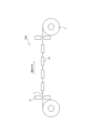
- FIG. 2 is a schematic diagram for explaining an example of the configuration of a dehydrogenation device according to Embodiment 1, in which (A) is a perspective view of the dehydrogenation device, (B) is a diagram of the dehydrogenation device seen from side a side, ( C) is an example of a diagram of an example of a dehydrogenation device viewed from side b, and (D) is a diagram of another example of the dehydrogenation device viewed from side b.
- FIG. 3 is a diagram illustrating an example of the configuration of a dehydrogenation device according to Embodiment 2, viewed from the winding axis direction of a steel plate coil.
- (A) and (B) are diagrams schematically showing an example of an installation mode of a pair of electromagnets 60A and 60B as a magnetic field applying device to a discharged steel plate in a dehydrogenation apparatus according to a second embodiment.
- a numerical range expressed using “ ⁇ ” means a range that includes the numerical values written before and after " ⁇ " as lower and upper limits.
- “steel plate” is a general term that includes hot rolled steel plates, cold rolled steel plates, annealed steel plates obtained by further annealing these steel plates, and plated steel plates with a plating film formed on the surfaces thereof.
- the shape of the "steel plate” is not limited, and includes both a steel plate coil and a rolled-out steel strip.
- This dehydrogenation device applies a steady magnetic field along the width direction of the steel plate to reduce the amount of diffusible hydrogen in the steel. According to this dehydrogenation apparatus, since heat treatment on the steel plate is not essential, there is no concern that the structural characteristics of the steel plate will change, and the amount of hydrogen diffused in the steel can be reduced.
- a steady magnetic field is applied along the width direction of the steel sheet. According to the present method for producing a steel sheet, since heat treatment on the steel sheet is not essential, the amount of diffused hydrogen in the steel can be reduced without fear of changing the structural characteristics of the steel sheet.
- the dehydrogenation device includes a housing part that stores a steel plate coil C obtained by winding a steel strip into a coil shape, and a steady magnetic field is applied along the plate width direction of the steel plate coil housed in the housing part.
- This is a dehydrogenation device having a magnetic field application device. In various steps in manufacturing steel sheets, steel strips are wound into steel sheet coils.
- the method for manufacturing a steel plate according to the present embodiment includes a magnetic field application step of applying a steady magnetic field along the width direction of a steel plate coil obtained by winding a steel strip into a coil shape.
- a magnetic field application step of applying a steady magnetic field along the width direction of a steel plate coil obtained by winding a steel strip into a coil shape.
- steel strips are wound into steel sheet coils.
- the dehydrogenation device and the method for manufacturing a steel plate according to the present embodiment by applying a steady magnetic field along the thickness direction of the steel plate coil, the amount of diffusible hydrogen in the steel is reduced and hydrogen embrittlement resistance is reduced. A steel plate with excellent properties can be obtained.
- steel plate coils since the steel strip is subjected to bending deformation and the lattice spacing on the radially outer surface of the steel strip is expanded, hydrogen diffusion paths are likely to be formed radially outward. it is conceivable that.
- the steel strip with the lattice spacing on the radially outer surface expanded is further expanded in the sheet width direction. Therefore, diffusible hydrogen in steel can be more suitably reduced.
- FIG. 1 shows an example of the configuration of a magnetic field application device.
- the magnetic field application device 60 includes a pair of electromagnets 60A and 60B located outside both ends of the steel plate coil C in the plate width direction.
- the electromagnets 60A and 60B each include iron cores 62A and 62B, coils 64A and 64B around which these iron cores 62A and 62B are wound, and a drive power source (not shown) for passing current through these coils 64A and 64B.
- the electromagnets 60A, 60B can be magnetized and a steady magnetic field can be generated.
- the axial direction of the coils 64A and 64B coincides with the width direction of the steel plate coil C.
- the pair of electromagnets 60A and 60B each have magnetic pole faces 66A and 66B that face the end face of the steel plate coil C in the plate width direction with a predetermined distance therebetween.
- one magnetic pole surface 66A can be made the N pole and the other magnetic pole surface 66B can be made the S pole.
- the pair of magnetic pole surfaces 66A and 66B are located at the same position with respect to both end portions of the steel plate coil C, and face each other with the steel plate coil C in between. Therefore, as shown in FIG. 1, the main magnetic flux of the steady magnetic field generated by the pair of electromagnets 60A and 60B is directed from the magnetic pole face 66A (N pole) to the magnetic pole face 66B (S pole), and in that direction. coincides with the width direction of the steel plate coil C. Thereby, a steady magnetic field can be applied uniformly along the width direction of the steel plate coil C.
- continuous direct current means a direct current whose current value is maintained continuously (preferably constant) rather than in a pulsed manner.
- a "steady magnetic field” means a magnetic field that is maintained continuously rather than in a pulsed manner, and includes a magnetic field formed by a stationary magnet and a magnetic field formed by an electromagnet supplied with continuous direct current.
- the "surface of the steel plate coil” means the surface of the steel plate located at the outermost peripheral portion in the radial direction of the steel plate coil C.
- the installation manner of the pair of electromagnets 60A and 60B is preferably as described above, the installation manner is not limited as long as a steady magnetic field with a magnetic flux component in the sheet width direction of the steel sheet coil C is generated.
- the configuration of the magnetic field application device 60 is not limited to the pair of electromagnets 60A and 60B as long as a steady magnetic field with a magnetic flux component in the width direction of the cold rolled steel sheet S is generated.
- the magnetic field applying device 60 may be only one of the electromagnet 60A and the electromagnet 60B. If the magnetic field formed by one of the electromagnets is strong enough to apply a magnetic field along the width direction of the steel plate coil C over the entire width of the steel plate coil C, only one of the electromagnets may be used.
- FIG. 2 shows an example of a dehydrogenation device for reducing diffusible hydrogen in steel by applying a steady magnetic field to the steel plate coil C using a magnetic field application device 60.
- FIG. 2(A) is a perspective view of the dehydrogenation device 300a.
- FIG. 2(B) is a diagram of the dehydrogenation device 300a viewed from the side a side. As shown in FIGS.
- the dehydrogenation device 300a includes a housing section 80 for housing the steel sheet coil C, and the steel sheet coil C accommodated in the housing section 80 is , a magnetic field application device 60 that applies a steady magnetic field.
- a magnetic field application device 60 that applies a steady magnetic field.
- the number and arrangement of the magnetic field application devices 60 are not particularly limited, in the example of FIG. 2, a plurality of magnetic field application devices 60 are arranged outside the end portion of the steel sheet coil C in the sheet width direction.
- a drive power source is coupled to each magnetic field application device 60, and a steady magnetic field is applied from the magnetic field application device 60 along the width direction of the steel sheet coil C. is applied.
- the housing portion 80 may be capable of housing a plurality of steel plate coils C.
- a coil holding section 90 is appropriately provided in the dehydrogenation device 300a.
- the coil holding part 90 is not particularly limited, when the steel plate coil C is placed so that the winding axis direction of the steel plate coil C is parallel to the floor of the dehydrogenation apparatus 300a, the coil holding part 90 is as shown in FIG. As shown in (A), in order to prevent the steel plate coil C from rolling within the dehydrogenation device 300a, it may be a pair of rod-shaped members that sandwich the steel plate coil C from both sides.
- the coil holding part 90 may be a pair of rod-shaped members having a concave arc-shaped upper surface along an arc drawn by the outermost circumference of the steel plate coil C, as shown in FIG. 2(A). Further, although not shown, the steel plate coil C may be placed so that the direction of the winding axis is perpendicular to the floor of the dehydrogenation apparatus 300a.
- the magnetic flux density in the sheet width direction of the steel sheet coil C is preferably 0.1 T or more, and 0.1 T or more. It is more preferably 2T or more, and even more preferably 0.5T or more.
- the magnetic flux density of the steel sheet coil C in the sheet width direction is preferably 15T or less, more preferably 14T or less.
- the magnetic flux density in the width direction of the cold rolled steel sheet S can be adjusted by adjusting the number of turns of the coil and the current value.
- Magnetic flux density in the width direction of the steel plate coil can be measured in-line by installing a Tesla meter near the end face in the width direction of the steel plate coil C and near the magnetic field generation surface of the magnetic field application device 60. .
- the "magnetic flux density of the steel sheet coil in the sheet width direction" can be determined in advance off-line.
- the time for applying the steady magnetic field to the steel plate coil C is not particularly limited.
- a steady magnetic field is applied to the steel sheet coil after hot rolling or cold rolling, so unlike the case where a steady magnetic field is applied while the steel strip is passed through, the steady magnetic field is applied without any restriction on the application time.
- a magnetic field can be applied. Since it is presumed that the longer the time for applying the steady magnetic field, the more diffusible hydrogen can be reduced, the time for applying the steady magnetic field is preferably 0.5 minutes or more.
- the application time of the steady magnetic field is more preferably 30 minutes or more, and even more preferably 60 minutes or more.
- the application time of the steady magnetic field is preferably 30,000 minutes or less, more preferably 10,000 minutes or less, and even more preferably 1,000 minutes or less.
- Examples of the method of controlling the application time of the steady magnetic field include a method of controlling the driving time of the magnetic field application device 60.
- the dehydrogenation device 300a may further include a heating section for applying a steady magnetic field while heating the steel plate coil C.
- the temperature of the steel plate coil C in the magnetic field application step is not particularly limited. This is because, according to the present embodiment, diffusible hydrogen in the steel can be reduced without heating and holding the steel plate coil C. However, by applying a steady magnetic field while heating the steel sheet coil C by the heating section, the diffusion rate of hydrogen can be further increased, and therefore the amount of diffusible hydrogen in the steel can be further reduced. Therefore, the temperature of the steel plate coil C when applying a steady magnetic field is preferably 30°C or higher, more preferably 50°C or higher, and even more preferably 100°C or higher.
- the upper limit of the temperature of the steel sheet coil C in the magnetic field application step is not particularly limited, but from the viewpoint of suitably preventing structural changes in the steel sheet coil C, the upper limit is 300° C., except when a steady magnetic field is applied during batch annealing, as described later.
- the temperature of the steel plate coil C when applying a steady magnetic field is based on the temperature at the 1/2 position in the radial direction of the steel plate coil.
- the temperature at the radial 1/2 position of the steel plate coil is measured by directly inserting a thermocouple at the radial 1/2 position of the steel plate coil and measuring the temperature of the steel strip located at the radial 1/2 position. can.
- the steel plate coil C can be heated by common methods such as installing a heater on the side wall of the housing, or blowing high-temperature air generated externally into the housing and circulating it within the housing. I do not care.
- the dehydrogenation device 300a may further include a magnetic field blocking part that prevents a steady magnetic field from being transmitted to the outside of the dehydrogenation device 300a.
- the magnetic field blocking part may be, for example, a magnetic field blocking material provided so as to surround the inner wall of the housing part 80.
- the amount of diffusible hydrogen in the product coil C obtained after applying a magnetic field can be reduced to 0.50 mass ppm or less.
- the amount of diffusible hydrogen in the steel after application of the magnetic field is preferably 0.30 mass ppm or less, more preferably 0.20 mass ppm or less.
- the amount of diffusible hydrogen in the product coil C is measured as follows. A test piece with a length of 30 mm and a width of 5 mm is taken from a half position in the radial direction of the product coil. When the steel sheet is a hot-dip galvanized steel sheet or an alloyed hot-dip galvanized steel sheet, the hot-dip galvanized layer or alloyed hot-dip galvanized layer of the test piece is removed by grinding or alkali. Thereafter, the amount of hydrogen released from the test piece is measured by thermal desorption spectrometry (TDS).
- TDS thermal desorption spectrometry
- the dehydrogenation device 300a and the method for manufacturing a steel plate according to this embodiment can be applied to manufacturing a hot rolled steel plate.
- the steel plate manufacturing system includes a hot rolling device that hot-rolls a steel slab to produce a hot-rolled steel plate, and a hot-rolled steel plate winding device that winds up the hot-rolled steel plate to obtain a hot-rolled coil. and a steel sheet dehydrogenation device in which the hot rolled coil is the steel sheet coil C.
- a hot rolling apparatus hot-rolls a steel slab having a known composition by rough rolling and finish rolling to produce a hot-rolled steel plate.
- the hot-rolled steel sheet winding device winds up the hot-rolled steel sheet to form a hot-rolled coil.
- the dehydrogenation device 300a uses the hot-rolled coil as a steel plate coil C and applies a steady magnetic field to the hot-rolled coil under the above-described conditions.
- the amount of diffusible hydrogen in the steel can be reduced, and a hot rolled steel sheet with excellent hydrogen embrittlement resistance can be obtained.
- the obtained hot-rolled steel sheet may be further subjected to cold rolling to obtain a cold-rolled steel sheet.
- the method for manufacturing a steel plate according to this application example includes the steps of hot rolling a steel slab to obtain a hot rolled steel plate, and winding up the hot rolled steel plate to obtain a hot rolled coil.
- the coil is the steel plate coil described above.
- the method for producing a hot rolled coil before applying a steady magnetic field is not particularly limited, and a steel slab having a known composition is subjected to hot rolling consisting of rough rolling and finish rolling to obtain a hot rolled steel plate.
- a hot-rolled coil may be obtained by winding a steel plate according to a known method.
- the amount of diffusible hydrogen in the steel can be reduced, and a hot-rolled steel sheet with excellent hydrogen embrittlement resistance can be obtained.
- the obtained hot-rolled steel sheet may be further subjected to cold rolling to obtain a cold-rolled steel sheet.
- the dehydrogenation device 300a and the method for manufacturing a steel plate according to the present embodiment can also be applied to manufacturing a cold rolled steel plate.
- the steel plate manufacturing system includes a cold rolling device that cold-rolls a hot-rolled steel plate to produce a cold-rolled steel plate, and a cold-rolled steel plate winder that winds up the cold-rolled steel plate to obtain a cold-rolled coil. and a dehydrogenation device 300a that uses the cold-rolled coil as the steel sheet coil C.
- the cold rolling equipment applies or does not perform hot-rolled plate annealing on a known hot-rolled steel plate, and applies one cold rolling process to a hot-rolled steel plate after hot rolling or a hot-rolled steel plate after hot-rolled plate annealing.
- a cold-rolled steel sheet having a final thickness is obtained by performing cold rolling two or more times with rolling or intermediate annealing in between.
- a cold-rolled steel sheet winding device winds up a cold-rolled steel sheet after cold rolling into a cold-rolled coil according to a known method.
- the dehydrogenation device 300a uses the cold-rolled coil as a steel plate coil C and applies a steady magnetic field to the cold-rolled coil under the above-mentioned conditions. By applying the steady magnetic field, the amount of diffusible hydrogen in the steel can be reduced, and a cold rolled steel sheet with excellent hydrogen embrittlement resistance can be obtained.
- the steel sheet manufacturing system may further include a dehydrogenation device 300a that can apply a steady magnetic field under the above-mentioned conditions to the hot rolled coil obtained by winding up the hot rolled steel sheet after hot rolling. good.
- the hot-rolled steel sheet is taken out from the hot-rolled coil after the magnetic field has been applied and cold-rolled to form a cold-rolled coil, and a steady magnetic field is further applied to the cold-rolled coil by the dehydrogenation device 300a, thereby dehydrogenating the steel.
- a steady magnetic field is further applied to the cold-rolled coil by the dehydrogenation device 300a, thereby dehydrogenating the steel.
- the method for manufacturing a steel plate according to this application example includes a step of cold rolling a hot rolled steel sheet to obtain a cold rolled steel sheet, and a step of winding the cold rolled steel sheet to obtain a cold rolled coil.
- the coil is the steel plate coil described above.
- the method of manufacturing the cold rolled coil before applying a steady magnetic field is not particularly limited.
- a steel slab having a known composition is subjected to hot rolling consisting of rough rolling and finish rolling to obtain a hot rolled steel plate, and the hot rolled steel plate is subjected to or without hot rolling annealing,
- a cold-rolled steel plate having a final thickness obtained by subjecting a hot-rolled steel plate after hot rolling or a hot-rolled steel plate after hot-rolled plate annealing to one cold rolling or two or more cold rollings with intermediate annealing in between. can do.
- the cold-rolled steel sheet after cold rolling is wound into a cold-rolled coil according to a known method.
- the amount of diffusible hydrogen in the steel can be reduced, and a cold-rolled steel sheet with excellent hydrogen embrittlement resistance can be obtained.
- a hot-rolled steel sheet after hot rolling is wound up to form a hot-rolled coil, and a steady magnetic field is also applied to the hot-rolled coil under the conditions described above. It may be applied.
- the hot-rolled steel sheet is taken out from the hot-rolled coil after the magnetic field has been applied, cold-rolled to form a cold-rolled coil, and a steady magnetic field is further applied to the cold-rolled coil to reduce the amount of diffusible hydrogen in the steel. can be further reduced to obtain a steel sheet with particularly excellent hydrogen embrittlement resistance.
- the type of hot-rolled steel sheet or cold-rolled steel sheet to which a steady magnetic field is applied is not particularly limited.
- the composition of the steel plate is not particularly limited, a steel plate having the following composition is exemplified as a steel plate to which the embodiment can be particularly suitably applied.
- the appropriate range of the composition of the steel sheet and the reason for its limitation will be explained.
- [Essential ingredients] C 0.030% or more and 0.800% or less C is an element necessary to increase strength. Particularly suitable strength can be obtained by setting the C content to 0.030% or more. Furthermore, by setting the C content to 0.800% or less, embrittlement of the material itself can be particularly preferably prevented. From this viewpoint, the amount of C is preferably 0.030% or more, and preferably 0.800% or less. The amount of C is more preferably 0.080% or more. Moreover, the amount of C is more preferably 0.500% or less.
- Si 0.01% or more and 3.00% or less
- Si is a solid solution strengthening element that becomes a substitutional solid solution and greatly hardens the material, and is effective for increasing the strength of the steel plate.
- the amount of Si is preferably 0.01% or more.
- the Si amount is set to 3.00. % or less. Therefore, the content of Si is preferably 0.01% or more, and preferably 3.00% or less. The content of Si is more preferably 0.10% or more, and more preferably 2.50% or less.
- Mn 0.01% or more and 10.00% or less Mn increases the strength of the steel plate by solid solution strengthening.
- the amount of Mn is preferably 0.01% or more.
- the amount of Mn is 10.00% or less.
- the amount of Mn is more preferably 0.5% or more, and more preferably 8.00% or less.
- P 0.001% or more and 0.100% or less
- P is an element that has a solid solution strengthening effect and can be added depending on the desired strength. In order to obtain these effects, it is preferable that the amount of P be 0.001% or more.
- the amount of P be 0.001% or more.
- the amount of P is preferably 0.001% or more, and preferably 0.100% or less.
- the amount of P is more preferably 0.003% or more. Further, the amount of P is more preferably 0.050% or less.
- the amount of S is preferably 0.0200% or less, more preferably 0.0100% or less, and even more preferably 0.0050% or less.
- the lower limit of the amount of S is not particularly limited, but due to constraints on production technology, the amount of S is preferably 0.0001% or more, more preferably 0.0050% or more.
- the amount of N is preferably 0.0100% or less, more preferably 0.0070% or less.
- the lower limit of the amount of N is not particularly limited, due to constraints on production technology, the amount of N is preferably 0.0005% or more, more preferably 0.0010% or more.
- Al acts as a deoxidizing agent and is an effective element for improving the cleanliness of steel, and is preferably added in the deoxidizing step.
- the amount of Al is preferably 0.001% or more.
- the Al content is preferably 2.000% or less.
- the amount of Al is more preferably 0.010% or more. Further, the amount of Al is more preferably 1.200% or less.
- the component composition is further expressed in mass%: Ti: 0.200% or less, Nb: 0.200% or less, V: 0.500% or less, W: 0.500% or less, B: 0.0050% or less, Ni : 1.000% or less, Cr: 1.000% or less, Mo: 1.000% or less, Cu: 1.000% or less, Sn: 0.200% or less, Sb: 0.200% or less, Ta: 0 .100% or less, Ca: 0.0050% or less, Mg: 0.0050% or less, Zr: 0.0050% or less, and REM: 0.0050% or less. It's okay.
- Ti 0.200% or less Ti contributes to increasing the strength of the steel sheet by precipitation strengthening of the steel and fine grain strengthening by suppressing the growth of ferrite crystal grains.
- adding Ti it is preferably 0.005% or more.
- the amount of Ti is more preferably 0.010% or more. Further, by setting the Ti amount to 0.200% or less, precipitation of carbonitrides can be suitably prevented and formability can be further improved. Therefore, when adding Ti, it is preferable that the amount added is 0.200% or less.
- the amount of Ti is more preferably 0.100% or less.
- Nb 0.200% or less
- V 0.500% or less
- W 0.500% or less
- Nb, V, and W are effective for precipitation strengthening of steel.
- each of them be 0.005% or more.
- Nb, V, and W it is preferable that each of them be 0.010% or more.
- the amount of carbonitride precipitation can be suitably prevented similarly to Ti, and formability can be further improved. can. Therefore, when adding Nb, the amount added is preferably 0.200% or less, more preferably 0.100% or less.
- V and W are added, their amounts are preferably each 0.500% or less, more preferably each 0.300% or less.
- B 0.0050% or less B is effective in strengthening grain boundaries and increasing the strength of steel sheets.
- B is preferably 0.0003% or more.
- B be 0.0050% or less. Therefore, when B is added, the amount added is preferably 0.0050% or less, more preferably 0.0030% or less.
- Ni 1.000% or less
- Ni is an element that increases the strength of steel through solid solution strengthening. When adding Ni, it is preferably 0.005% or more. Further, from the viewpoint of further improving ductility by reducing the area ratio of hard martensite, Ni is preferably 1.000% or less. Therefore, when adding Ni, the amount added is preferably 1.000% or less, more preferably 0.500% or less.
- Cr: 1.000% or less, Mo: 1.000% or less Cr and Mo have the effect of improving the balance between strength and formability, so they can be added as necessary.
- Cr: 0.005% or more and Mo: 0.005% or more it is preferable that Cr and Mo be 1.000% or less, and 1.000% or less, respectively. It is preferable that Cr and Mo be Cr: 0.500% or less and Mo: 0.500% or less, respectively.
- Cu 1.000% or less
- Cu is an element effective in strengthening steel, and can be added as necessary.
- it is preferably 0.005% or more.
- the amount is preferably 1.000% or less, and 0.200% or less. It is more preferable.
- Sn 0.200% or less
- Sb 0.200% or less
- Sn and Sb suppress decarburization in an area of several tens of ⁇ m on the steel plate surface layer caused by nitriding and oxidation of the steel plate surface, so they may be added as necessary. Adding it is effective in ensuring strength and material stability.
- Sn and Sb it is preferable to add each to 0.002% or more.
- the content thereof is preferably 0.200% or less, and more preferably 0.050% or less.
- Ta 0.100% or less Like Ti and Nb, Ta generates alloy carbides and alloy carbonitrides and contributes to high strength. In addition, by partially forming a solid solution in Nb carbide and Nb carbonitride and forming composite precipitates such as (Nb, Ta) (C, N), coarsening of the precipitates is significantly suppressed and precipitation strengthening is achieved. This is thought to have the effect of stabilizing the contribution of For this reason, it is preferable to contain Ta. Here, when Ta is added, it is preferably 0.001% or more. The upper limit of the amount of Ta is not particularly limited, but from the viewpoint of reducing costs, when adding Ta, the content is preferably 0.100% or less, and preferably 0.050% or less. More preferred.
- Ca 0.0050% or less, Mg: 0.0050% or less, Zr: 0.0050% or less, REM: 0.0050% or less
- Ca, Mg, Zr, and REM make the shape of the sulfide spherical and improve moldability. It is an effective element to improve the negative effects of sulfide on When these elements are added, it is preferable to add each of them in an amount of 0.0005% or more. Furthermore, in order to better prevent the increase of inclusions, etc., and better prevent surface and internal defects, when adding Ca, Mg, Zr, and REM, the amount of each should be 0.0050% or less. is preferable, and more preferably 0.0020% or less.
- This embodiment can also be suitably applied to high-strength steel sheets, in particular where hydrogen embrittlement is a problem.
- the steel plate manufactured in this embodiment may be a high-strength steel plate having a tensile strength of 590 MPa or more, more preferably 1180 MPa or more, and still more preferably 1470 MPa or more. Note that the tensile strength of the steel plate is measured in accordance with JIS Z 2241 (2011). Delayed fracture due to hydrogen embrittlement is often a problem in high-strength steel plates, but according to this embodiment, it is possible to manufacture high-strength steel plates with excellent hydrogen embrittlement resistance without compromising tensile strength. can.
- a steady magnetic field can be applied to known stainless steel to manufacture stainless steel with excellent hydrogen embrittlement resistance.
- the component composition and the reason for its limitation will be explained when the steel plate is a stainless steel plate.
- [Essential ingredients] C 0.001% or more and 0.400% or less C is an essential element for obtaining high strength in stainless steel. However, when the C content exceeds 0.400%, it combines with Cr and precipitates as carbides during tempering in steel manufacturing, and the carbides deteriorate the corrosion resistance and toughness of the steel. On the other hand, if the C content is less than 0.001%, sufficient strength cannot be obtained, and if it exceeds 0.400%, the deterioration becomes noticeable. Therefore, the C content is set to 0.001% or more and 0.400% or less. The C content is preferably 0.005% or more. Further, the C content is preferably 0.350% or less.
- Si 0.01% or more and 2.00% or less Si is an element useful as a deoxidizing agent. This effect can be obtained by setting the Si content to 0.01% or more. However, when Si is contained excessively, Si dissolved in the steel deteriorates the workability of the steel. Therefore, the upper limit of the Si content is set to 2.00%.
- the Si content is preferably 0.05% or more. Further, the Si content is preferably 1.8% or less.
- Mn 0.01% or more and 5.00% or less Mn has the effect of increasing the strength of steel. These effects can be obtained by containing 0.01% or more of Mn. However, when the Mn content exceeds 5.00%, the workability of the steel decreases. Therefore, the upper limit of the Mn content is set to 5.00%.
- the Mn content is preferably 0.05% or more. Further, the Mn content is preferably 4.6% or less.
- P 0.001% or more and 0.100% or less Since P is an element that promotes grain boundary fracture due to grain boundary segregation, a lower content is preferable, and the upper limit is set to 0.100%. Preferably the P content is 0.030% or less. More preferably, the P content is 0.020% or less. Note that the lower limit of the P content is not particularly limited, but from the viewpoint of production technology, it is set to 0.001% or more.
- S 0.0001% or more and 0.0200% or less
- S is an element that exists in the form of sulfide inclusions such as MnS and reduces ductility and corrosion resistance, especially when the content exceeds 0.0200%. In some cases, these adverse effects are noticeable. Therefore, it is desirable that the S content be as low as possible, and the upper limit of the S content is 0.0200%. Preferably the S content is 0.010% or less. More preferably, the S content is 0.005% or less. Note that the lower limit of the S content is not particularly limited, but from the viewpoint of production technology, it is set to 0.0001% or more.
- Cr 9.0% or more and 28.0% or less
- Cr is a basic element constituting stainless steel, and is also an important element that exhibits corrosion resistance.
- the Cr content is set to 9.0% or more and 28.0% or less.
- the Cr content is preferably 10.0% or more. Further, the Cr content is preferably 25.0% or less.
- Ni 0.01% or more and 40.0% or less
- Ni is an element that improves the corrosion resistance of stainless steel, but if it is less than 0.01%, its effect will not be fully demonstrated. In addition to hardening and deteriorating formability, it also makes stress corrosion cracking more likely. Therefore, the Ni content is set to 0.01% or more and 40.0% or less. The Ni content is preferably 0.1% or more. Further, the Ni content is preferably 30.0% or less.
- N 0.0005% or more and 0.500% or less N is an element harmful to improving the corrosion resistance of stainless steel, but is also an austenite-forming element. If the content exceeds 0.5%, it will precipitate as nitrides during heat treatment, and the corrosion resistance and toughness of stainless steel will deteriorate. Therefore, the upper limit of the N content is set to 0.500%, preferably 0.20%.
- Al 3.000% or less
- Al is added as a deoxidizing element and also has the effect of suppressing peeling of oxide scale.
- adding more than 3.000% results in a decrease in elongation and deterioration in surface quality. Therefore, the upper limit of the Al content is set to 3.000%.
- the lower limit of the Al content is not particularly limited, it is preferably 0.001% or more. More preferably, the Al content is 0.01% or more. Further, the Al content is preferably 2.5% or less.
- the composition of the stainless steel is further expressed in mass%: Ti: 0.500% or less, Nb: 0.500% or less, V: 0.500% or less, W: 2.000% or less, B: 0.0050%.
- Mo 2.000% or less
- Cu 3.000% or less
- Sn 0.500% or less
- Sb 0.200% or less
- Ta 0.100% or less
- Ca 0.0050% or less
- It may contain at least one element selected from the group consisting of Mg: 0.0050% or less, Zr: 0.0050% or less, and REM: 0.0050% or less.
- Ti 0.500% or less Ti is an element added to combine with C, N, and S to improve corrosion resistance, intergranular corrosion resistance, and deep drawability. However, if it is added in an amount exceeding 0.500%, the solid solution Ti will harden the stainless steel and deteriorate the toughness. Therefore, the upper limit of the Ti content is set to 0.500%. Although the lower limit of the Ti content is not particularly limited, it is preferably 0.003% or more. The Ti content is more preferably 0.005% or more. Further, the Ti content is preferably 0.300% or less.
- Nb 0.500% or less
- Nb is an element added to combine with C, N, and S to improve corrosion resistance, intergranular corrosion resistance, and deep drawability. Further, in addition to improving workability and high-temperature strength, it is added as necessary to suppress crevice corrosion and promote re-passivation. However, since excessive addition causes the stainless steel to become hard and deteriorates formability, the upper limit of the Nb content is set to 0.500%. Although the lower limit of the Nb content is not particularly limited, it is preferably 0.003% or more. The Nb content is more preferably 0.005% or more. Further, the Nb content is preferably 0.300% or less.
- V 0.500% or less V is added as necessary to suppress crevice corrosion.
- the upper limit of the V content is set to 0.500%.
- the V content is preferably 0.01% or more, and more preferably 0.03% or more. Further, the V content is preferably 0.300% or less.
- W 2.000% or less W contributes to improving corrosion resistance and high-temperature strength, so it is added as necessary.
- the upper limit of the W content is set at 2.000%.
- the lower limit of the W content is not particularly limited, it is preferably 0.050% or more. More preferably, the W content is 0.010% or more. Further, the W content is preferably 1.500% or less.
- B 0.0050% or less
- the lower limit of the B content is not particularly limited, it is preferably 0.0002% or more. More preferably, the B content is 0.0005% or more. Further, the B content is preferably 0.0035% or less.
- Mo 2.000% or less
- Mo is an element that improves corrosion resistance, and is an element that suppresses crevice corrosion, especially when it has a crevice structure. However, if it exceeds 2.000%, the moldability will deteriorate significantly, so the upper limit of the content is set at 2.000%.
- the lower limit of the Mo content is not particularly limited, it is preferably 0.005% or more. More preferably, the Mo content is 0.010% or more. Further, the Mo content is preferably 1.500% or less.
- Cu 3.000% or less
- Cu is an austenite stabilizing element and is effective in refining crystal grains through phase transformation. Further, it is added as necessary to suppress crevice corrosion and promote repassivation. However, excessive addition causes hardening and deterioration of toughness and formability, so the upper limit of its content is set at 3.000%.
- the lower limit of the Cu content is not particularly limited, it is preferably 0.005% or more. More preferably, the Cu content is 0.010% or more. Further, the Cu content is preferably 2.000% or less.
- Sn 0.500% or less Sn contributes to improving corrosion resistance and high temperature strength, so it is added as necessary. However, if added in excess of 0.500%, slab cracking may occur during steel sheet production, so the upper limit of its content is set to 0.500% or less.
- the lower limit of the Sn content is not particularly limited, it is preferably 0.002% or more. It is more preferable that the Sn content is 0.005% or more. Further, the Sn content is preferably 0.300% or less.
- Sb 0.200% or less
- Sb is an element that segregates at grain boundaries and acts to increase high-temperature strength. However, if it exceeds 0.200%, Sb segregation will occur and cracks will occur during welding, so the upper limit of the content is set at 0.200%.
- the lower limit of the Sb content is not particularly limited, it is preferably 0.002% or more. More preferably, the Sb content is 0.005% or more. Further, the Sb content is preferably 0.100% or less.
- Ta 0.100% or less Ta is added as necessary because it combines with C and N and contributes to improving toughness. However, if it is added in excess of 0.100%, the effect will be saturated and the manufacturing cost will increase, so the upper limit of the content is set at 0.100%.
- the lower limit of the Ta content is not particularly limited, it is preferably 0.002% or more. More preferably, the Ta content is 0.005% or more. Further, the Ta content is preferably 0.080% or less.
- Ca, Mg, Zr and REM have a sulfide shape. It is an effective element for spheroidizing and improving the adverse effects of sulfide on formability.
- the content of each element is preferably 0.0005% or more.
- the content of each element should be 0.0050% or less.
- the lower limit of the content of these elements is not particularly limited, it is preferable that the content of each element is 0.0002% or more.
- the content of each element is more preferably 0.0005% or more. Further, the content of each element is preferably 0.0035% or less.
- the cold-rolled steel sheet and hot-rolled steel sheet described above may be annealed. That is, the present steel plate manufacturing system may include an annealing device that anneals cold-rolled steel plates and hot-rolled steel plates.
- the timing of annealing is not particularly limited, but since hydrogen generally enters the steel during the annealing process, a steady magnetic field is applied during annealing in order to ultimately obtain a steel plate with excellent hydrogen embrittlement resistance. It is preferable to apply it before.
- the annealing device may be a batch annealing furnace or a continuous annealing device.
- the steel sheet manufacturing system includes a batch annealing furnace that performs batch annealing on a cold-rolled coil or a hot-rolled coil to obtain an annealed coil, and the annealed coil as the steel sheet coil C. It has a dehydrogenation device 300a.
- a batch annealing furnace performs batch annealing on a cold-rolled coil or a hot-rolled coil to produce an annealed coil. Note that in this specification, batch annealing means heating and holding in a batch annealing furnace, and does not include slow cooling after heating and holding.
- the annealed coil is cooled by furnace cooling or air cooling in a batch annealing furnace.
- the dehydrogenation apparatus 300a uses a steel plate coil C as an annealing coil, and applies a steady magnetic field to the steel plate coil C under the above-described conditions.
- the dehydrogenation device 300a may be provided separately from the batch annealing furnace, the housing section 80 and the heating section of the dehydrogenation device 300a may also serve as the batch annealing furnace.
- the batch annealing furnace may be provided with a magnetic field applying device 60 that applies a steady magnetic field to the steel sheet coil C housed in the furnace to produce a product coil, thereby forming the dehydrogenation device 300a.
- the application of the steady magnetic field can be performed after batch annealing and after cooling the annealed coil to room temperature.
- a steady magnetic field can also be applied.
- diffusible hydrogen can be reduced more efficiently when the temperature of the steel sheet is higher, so it is possible to perform batch annealing after cooling the annealed coil to room temperature, or apply a steady magnetic field while cooling the annealed coil. By applying , diffusible hydrogen in steel can be reduced more efficiently.
- the steel plate manufacturing method includes a step of batch annealing a cold rolled coil or hot rolled coil obtained by winding a cold rolled steel plate or hot rolled steel plate to obtain an annealed coil.
- the annealed coil is used as the steel plate coil, and a steady magnetic field is applied to the annealed coil under the above-mentioned conditions.
- a cold-rolled steel sheet or a hot-rolled steel sheet is wound up by a known method to form a cold-rolled coil or a hot-rolled coil.
- the cold rolled coil or the hot rolled coil is placed in a batch annealing furnace, and batch annealing is performed in the batch annealing furnace to obtain an annealed coil.
- the annealed coil is cooled by furnace cooling or air cooling in a batch annealing furnace.
- a steady magnetic field is applied to the annealed coil under the conditions described above.
- the application of a steady magnetic field to the annealed coil may be performed during batch annealing, that is, while the cold-rolled coil or hot-rolled coil is being heated and held.
- the application of the steady magnetic field may be performed after batch annealing, that is, after the cold-rolled coil or hot-rolled coil is heated and held.
- the application of the steady magnetic field may be performed after batch annealing and after cooling the annealed coil to room temperature, or may be performed while cooling the annealed coil.
- a steady magnetic field is applied to the annealed coil while cooling the annealed coil during or after batch annealing.
- Application of a steady magnetic field to the annealed coil can be performed within a batch annealing furnace, or can be performed by taking the annealed coil out of the batch annealing furnace.
- a steady magnetic field is applied to the annealing coil in a batch annealing furnace.
- Annealing can also be performed by passing a cold rolled steel sheet or a hot rolled steel sheet through a continuous annealing device (Continuous Annealing Line: CAL).
- a continuous annealing device Continuous Annealing Line: CAL.
- the steel sheet manufacturing system includes a pre-annealing device that discharges the cold-rolled steel sheet or the hot-rolled steel sheet from the cold-rolled coil or the hot-rolled coil, and the cold-rolled steel sheet or the hot-rolled steel sheet.
- the pre-annealing payout device pays out a cold rolled steel plate or a hot rolled steel plate from a cold rolled coil or a hot rolled coil, and supplies the cold rolled steel plate or hot rolled steel plate to CAL.
- the CAL has a continuous annealing furnace in which a heating zone, a soaking zone, and a cooling zone are arranged in this order.
- the cooling zone may be composed of multiple cooling zones, in which case some of the cooling zones may be a holding zone that holds the cold-rolled steel strip in the cooling process within a certain temperature range, or a holding zone that holds the cold-rolled steel strip in the cooling process and reheats the steel plate in the cooling process. It may also be a reheating zone. Further, a preheating zone may be provided on the upstream side of the heating zone in the sheet passing direction.
- the pre-anneal payout device may be a payoff reel provided upstream of the continuous annealing furnace of the CAL.
- the annealed steel sheet winding device may be a tension reel provided downstream of the continuous annealing furnace of the CAL.
- CAL (A) a cold-rolled steel sheet or a hot-rolled steel sheet is discharged from a cold-rolled coil or a hot-rolled coil by a payoff reel, and (B) a heating zone, a soaking zone, and a cooling zone are separated from the upstream side in the sheet threading direction.
- the steel sheet is passed through a continuous annealing furnace located in the furnace, and (B-1) the cold-rolled steel sheet or hot-rolled steel sheet is annealed in the heating zone and the soaking zone to form an annealed steel sheet, and (B-2) it is annealed in the cooling zone.
- the steel plate is cooled and continuously annealed, (C) the annealed steel plate discharged from the continuous annealing furnace is continuously passed through the plate, and (D) the steel plate is wound up with a tension reel to form an annealed coil.
- the dehydrogenation device 300a uses the annealing coil as a steel sheet coil C, and applies a steady magnetic field to the annealing coil under the above-described conditions.
- the cooling method and cooling rate of the steel plate in the cooling zone are not particularly limited, and any cooling such as gas jet cooling, mist cooling, water cooling, etc. may be used.
- the method for producing a steel plate includes a step of discharging the cold rolled steel sheet from the cold rolled coil, a step of continuously annealing the cold rolled steel sheet to obtain an annealed steel sheet, and a step of the annealing. and a step of winding up a steel plate to obtain an annealed coil, and the annealed coil is used as the steel plate coil.
- CAL (A) a steel plate coil is unloaded by a payoff reel, (B) the steel plate is passed from the upstream side in the threading direction into an annealing furnace in which a heating zone, a soaking zone, and a cooling zone are located.
- the dehydrogenation apparatus 300a can also be applied to the production of plated steel sheets.
- the steel sheet manufacturing system according to this application example includes a plating device that forms a plating film on the surface of a hot-rolled steel sheet or a cold-rolled steel sheet to produce a plated steel sheet, and a plated steel sheet that winds up the plated steel sheet to obtain a plated steel sheet coil. It has a winding device and a dehydrogenation device 300a that uses the plated steel sheet coil as the steel sheet coil C.
- the plating apparatus forms a plating film on the surface of a hot-rolled steel sheet or a cold-rolled steel sheet as a base steel sheet to obtain a plated steel sheet.
- the plated steel sheet winding device winds up the plated steel sheet to form a plated steel sheet coil.
- the dehydrogenator 300a uses the plated steel coil as a steel plate coil C and applies a steady magnetic field to the plated steel coil under the above-described conditions. By applying the steady magnetic field, the amount of diffusible hydrogen in the steel can be reduced, and a plated steel sheet with excellent hydrogen embrittlement resistance can be obtained.
- a plated steel plate may be obtained by forming a plating film on the surface of a hot-rolled steel plate or a cold-rolled steel plate as a base steel plate, and the plated steel plate may be used as a steel plate coil to which a steady magnetic field is applied.
- the method for manufacturing the steel plate includes a step of forming a plating film on the surface of a hot-rolled steel plate or a cold-rolled steel plate to obtain a plated steel plate, and winding up the plated steel plate, obtaining a plated steel coil, the plated steel coil being the steel plate coil.
- the type of plating device is not particularly limited, but may be, for example, a hot-dip galvanizing device.
- the hot-dip galvanizing equipment may be a continuous hot-dip galvanizing line (CGL) in one example.
- CGL continuous hot-dip galvanizing line
- the configuration of the CGL is not particularly limited, in one example, the CGL includes a continuous annealing furnace in which a heating zone, a soaking zone, and a cooling zone are arranged in this order, and hot-dip galvanizing equipment provided after the cooling zone.
- a cold rolled steel sheet or a hot rolled steel sheet is discharged from a cold rolled coil or a hot rolled coil by a payoff reel, and (B) a heating zone, a soaking zone, and a cooling zone are separated from the upstream side in the sheet threading direction.
- (B-1) The hot-rolled steel sheet or cold-rolled steel sheet is annealed in a reducing atmosphere containing hydrogen in the soaking zone to produce an annealed steel sheet, and (B-2 ) Cooling the annealed steel sheet in a cooling zone to perform continuous annealing, (C) Continue passing the annealed steel sheet discharged from the annealing furnace, and (C-1) Located downstream of the continuous annealing furnace in the sheet passing direction.
- An annealed steel sheet is immersed in a hot-dip galvanizing bath, and the annealed steel sheet is subjected to hot-dip galvanizing treatment to form a hot-dip galvanized steel sheet, and (D) the hot-dip galvanized steel sheet is wound up using a tension reel to form a hot-dip galvanized steel sheet coil.
- the dehydrogenation device 300a uses the hot-dip galvanized steel sheet coil as a steel sheet coil C, and applies a steady magnetic field to the hot-dip galvanized steel sheet coil under the above-described conditions. By applying the steady magnetic field, the amount of diffusible hydrogen in the steel can be reduced, and a hot-dip galvanized steel sheet with excellent hydrogen embrittlement resistance can be obtained.
- the method of forming a plating film on the surface of a hot-rolled steel sheet or a cold-rolled steel sheet is not particularly limited, but the plating process may include a hot-dip galvanizing process. That is, a hot-rolled steel sheet or a cold-rolled steel sheet may be subjected to hot-dip galvanizing treatment to produce a hot-dip galvanized steel sheet. In one example, a steel plate can be subjected to hot-dip galvanizing using a continuous hot-dip galvanizing line (CGL).
- CGL continuous hot-dip galvanizing line
- the steel sheet coil is (A) delivered by a payoff reel, and (B) the hot-rolled steel sheet or cold-rolled steel sheet is placed into an annealing furnace in which a heating zone, a soaking zone, and a cooling zone are located from the upstream side in the sheet threading direction.
- B-1 In the soaking zone, the hot-rolled steel sheet or cold-rolled steel sheet is annealed in a reducing atmosphere containing hydrogen to form an annealed steel sheet
- B-2) in the cooling zone the annealed steel sheet is cooled.
- C-1) Includes a step of subjecting the annealed steel sheet to hot-dip galvanizing treatment by immersing the annealed steel sheet in a hot-dip galvanizing bath located downstream of the annealing furnace in the sheet passing direction.
- the wound annealed coil is a hot-dip galvanized steel sheet coil made of hot-dip galvanized steel sheet.
- the plating device may include a hot-dip galvanizing device and an alloying furnace following the hot-dip galvanizing device.
- a hot-dip galvanizing device following the above-mentioned step (C-1), (C-2) the steel sheet is placed in an alloying furnace located downstream of the hot-dip galvanizing bath in the sheet passing direction.
- the hot-dip galvanizing is heated and alloyed by passing through the plate.
- the alloyed hot-dip galvanized steel sheet that has been passed through the alloying furnace and alloyed is wound up to become an alloyed hot-dip galvanized steel sheet coil.
- the dehydrogenation device 300a uses the alloyed hot-dip galvanized steel sheet coil as the steel sheet coil C, and applies a steady magnetic field to the alloyed hot-dip galvanized steel sheet coil under the above-described conditions. By applying the steady magnetic field, an alloyed hot-dip galvanized steel sheet with excellent hydrogen embrittlement resistance can be obtained.
- the plating process may include a hot-dip galvanizing process and a subsequent alloying process. That is, the hot-dip galvanized steel sheet may be further subjected to alloying treatment to obtain an alloyed hot-dip galvanized steel sheet, and a steady magnetic field may be applied to the hot-dip galvanized steel sheet.
- the steel sheet is placed in an alloying furnace located downstream of the hot-dip galvanizing bath in the sheet passing direction. The hot-dip galvanizing is heated and alloyed by passing through the plate.
- the alloyed hot-dip galvanized steel sheet that has been passed through the alloying furnace and alloyed is wound up to become an alloyed hot-dip galvanized steel sheet coil.
- the plating device can form not only a zinc plating film but also an Al plating film and a Fe plating film. Further, the plating device is not limited to a hot-dip plating device, but may be an electroplating device.
- the type of plating film that can be formed on the surface of the steel plate to which a steady magnetic field is applied is not particularly limited, and may be an Al plating film or an Fe plating film.
- the method for forming the plating film is not limited to the hot-dip plating process, but may also be an electroplating process.
- the steel sheet manufacturing system processes shape correction and surface roughness for hot rolled steel sheets, cold rolled steel sheets, and plated steel sheets having various plating films on the surface of the hot rolled steel sheets or cold rolled steel sheets obtained as described above. It may further include a skin pass rolling device that performs skin pass rolling for the purpose of adjustment and the like.
- a skin pass rolling device that performs skin pass rolling for the purpose of adjustment and the like.
- the hot rolled steel sheet, the cold rolled steel sheet, and the plated steel sheet having various plating films on the surface of the hot rolled steel sheet or cold rolled steel sheet obtained as described above are subjected to shape correction.
- skin pass rolling can be performed for the purpose of adjusting surface roughness.
- the reduction ratio in skin pass rolling is preferably controlled to 0.1% or more, and preferably 2.0% or less.
- the skin pass rolling device may be a device that is continuous with the CGL or CAL (in-line), or may be a device that is discontinuous with the CGL or CAL (off-line). Skin pass rolling may be performed at the desired rolling reduction at once, or skin pass rolling may be performed in several steps to achieve the desired rolling reduction.
- the steel plate manufacturing system includes a resin or oil coating on the surface of the hot-rolled steel plate, cold-rolled steel plate, and plated steel plate having various plating films on the surface of the hot-rolled steel plate or cold-rolled steel plate obtained as described above. It may further include coating equipment for performing various coating treatments. That is, various painting treatments such as resin or oil coating are applied to the surface of the hot-rolled steel sheet, cold-rolled steel sheet, and plated steel sheet having various plating films on the surface of the hot-rolled steel sheet or cold-rolled steel sheet obtained as described above. You can also do that.
- a dehydrogenation device includes a dispensing device for dispensing a steel strip from a steel plate coil, a threading device for passing the steel strip, a winding device for winding the steel strip, and a dispensing device for dispensing a steel strip from a steel plate coil, a threading device for passing the steel strip through the steel strip, a winding device for winding the steel strip, and a winding device for winding the steel strip.
- the plate apparatus includes a magnetic field applying device that applies a steady magnetic field along the width direction of the steel strip to the steel strip that is being passed through the plate device.
- the method for manufacturing a steel sheet according to Embodiment 2 of the present invention includes a step of discharging a steel strip from a steel sheet coil, a threading step of passing the steel strip through the steel strip, and winding the steel strip to form a product coil.
- the strip-threading step includes a magnetic field application step of applying a steady magnetic field to the steel strip along the thickness direction of the steel strip.
- the steel strip is paid out from the steel plate coil by the payout device, and the paid out steel strip is rewound again by the unwinding device, and when it reaches a predetermined packing mass, it is sheared and divided. In this embodiment, a steady magnetic field is applied to the steel strip discharged by this recoil line.
- the dehydrogenation device is a discontinuous device (offline) from the continuous annealing device or the continuous hot-dip galvanizing device, and the dehydrogenation device is capable of annealing, plating, and hot-dip galvanizing the steel strip. Does not include equipment for processing.
- Magnetic field application device 60 A magnetic field application device can be used to apply the steady magnetic field.
- the magnetic field application device applies a steady magnetic field along the thickness direction of the steel strip during threading, similar to the magnetic field application device 60 according to the first embodiment described above.
- the configuration of the magnetic field applying device 60 can be the same as in Embodiment 1, except that the object to which a steady magnetic field is applied is not the steel plate coil but the steel strip being threaded.
- FIG. 3 shows a view of a dehydrogenation apparatus 300b used in the method of manufacturing a steel plate according to the present embodiment, with the width direction of the steel strip S facing toward you.
- FIG. 3 is a diagram showing an example of a dehydrogenation device for applying a steady magnetic field to the steel strip S during threading by a magnetic field application device 60 to reduce diffusible hydrogen in the steel.
- a magnetic field application device 60 is arranged in the process of threading the steel strip S discharged by the discharge device.
- each electromagnet 60A, 60B has an iron core 62A, 62B, a coil 64A, 64B around which the iron core 62A, 62B is wound, and a current in these coils 64A, 64B. and a drive power source (not shown) for flowing.
- the dehydrogenation device 300b includes a threading device for threading the steel strip S from the payout device toward the winding device.
- the threading device includes, for example, a threading roll that threads the steel strip S toward a winding device.
- the pair of magnetic pole surfaces 66A and 66B of the magnetic field applying device 60 are located at the same position in the passing direction of the cold rolled steel sheet S and face each other across the steel strip being passed.
- the main magnetic flux of the steady magnetic field generated by the pair of electromagnets 60A and 60B is directed from the magnetic pole surface 66A (N pole) to the magnetic pole surface 66B (S pole), and the direction is It corresponds to the width direction of the steel strip inside.
- a steady magnetic field can be uniformly applied along the width direction of the steel strip during threading.
- the magnetic field application device 60 may have only one of the electromagnets 60A and 60B. If the magnetic field formed by one of the electromagnets is strong enough to apply a magnetic field along the width direction of the steel strip to the entire width of the steel strip being threaded, only one of the electromagnets may be used.
- the form for holding the electromagnets 60A and 60B at a constant interval in the dehydrogenation device 300b is not particularly limited, but for example, a box-shaped part is provided in the threading path so as to cover the steel strip S being threaded, and the Electromagnets 60 can be fixed to the inner wall of the shaped part at regular intervals.
- the magnetic flux density of the magnetic field applied to the steel strip during threading can be the same as in Embodiment 1.
- a steady magnetic field can be applied to the steel strip without restrictions on application time. Since it is presumed that the longer the time for applying the steady magnetic field, the more diffusible hydrogen can be reduced, the time for applying the steady magnetic field is preferably 0.5 minutes or more.
- the application time of the steady magnetic field is more preferably 30 minutes or more, and still more preferably 60 minutes or more.
- the application time of the steady magnetic field is preferably 30,000 minutes or less, more preferably 10,000 minutes or less, and even more preferably 1,000 minutes or less.
- the application time of the steady magnetic field is adjusted by the threading speed of the steel strip S and the number and position of magnetic field application devices (for example, the number and installation position of the plurality of magnetic field application devices 60 located along the width direction of the steel sheet). be able to.
- the amount of diffusible hydrogen in the product coil obtained after applying a magnetic field can be reduced to 0.50 mass ppm or less.
- the amount of diffusible hydrogen in the steel after application of the magnetic field is preferably 0.30 mass ppm or less, more preferably 0.20 mass ppm or less.
- the amount of diffusible hydrogen in the steel after applying the magnetic field can be measured in the same manner as in Embodiment 1.
- the dehydrogenation device 300b may further include a heating device 74 for applying a steady magnetic field while heating the steel strip S at 300° C. or lower.
- the temperature of the steel strip S during the magnetic field application step is not particularly limited. This is because, according to the present embodiment, diffusible hydrogen in the steel can be reduced without heating and holding the steel strip S. However, by applying a steady magnetic field while heating the steel strip S by the heating section, the diffusion rate of hydrogen can be further increased, and therefore the amount of diffusible hydrogen in the steel can be further reduced.
- the temperature of the steel strip S when applying a steady magnetic field is preferably 30°C or higher, more preferably 50°C or higher, and even more preferably 100°C or higher.
- the upper limit of the temperature of the steel strip S in the magnetic field application step is not particularly limited, but from the viewpoint of suitably preventing changes in the structure of the steel strip S, it is preferably 300° C. or less.
- the temperature of the steel strip S when applying a steady magnetic field is based on the temperature of the surface of the steel strip S.
- the surface temperature of the steel strip can be measured with a general radiation thermometer.
- the form in which the heating device 74 is provided is not particularly limited, for example, as shown in FIG.
- the heating device 74 can be provided in the threading path of the steel strip S. By providing the heating device 74 on the passing path of the steel strip S, the steel strip S can be heated uniformly.
- the heating device 74 is provided in the threading path of the steel strip S, as shown in FIG. 3, it is preferable to provide the heating device 74 upstream of the magnetic field applying device 60 in the threading path.
- a steady magnetic field can be applied to the sufficiently heated steel strip S. Further, for example, by covering the steel strip being threaded with the box-shaped part described above and installing a heater on the side wall of the box-shaped part, it is possible to apply a steady magnetic field while keeping the steel strip S heated.
- a steady magnetic field can be applied while heating and maintaining the steel strip S by blowing high-temperature air generated outside into the box-shaped section and circulating it within the box-shaped section.
- the heating method is not particularly limited, and may be either a combustion method or an electric method.
- heating device 74 may be an induction heating device.
- the dehydrogenation device 300b may further include a magnetic field blocking section that prevents the steady magnetic field from being transmitted to the outside of the dehydrogenation device 300b.
- a magnetic field blocking section may be, for example, a magnetic field blocking material that encloses and covers the steel strip S and the electromagnets 60A and 60B.
- the steel plate manufacturing system includes a hot rolling device that hot-rolls a steel slab to produce a hot-rolled steel plate, and a hot-rolled steel plate winding device that winds up the hot-rolled steel plate to obtain a hot-rolled coil. and a dehydrogenation device 300b in which the hot rolled coil is the steel plate coil.
- a hot-rolled steel sheet is taken out from a hot-rolled coil produced by a known hot-rolling device, and a steady magnetic field is applied under the above-mentioned conditions to the hot-rolled steel sheet during threading, thereby increasing the By reducing the amount of diffusible hydrogen, a hot rolled steel sheet with excellent hydrogen embrittlement resistance can be obtained.
- the method for manufacturing a steel sheet according to this embodiment can be applied to manufacturing a hot rolled steel sheet.
- the method for manufacturing a steel plate according to this application example includes the steps of hot rolling a steel slab to obtain a hot rolled steel plate, and winding up the hot rolled steel plate to obtain a hot rolled coil.
- the coil is the steel plate coil described above.
- the method of manufacturing the hot-rolled coil before applying a steady magnetic field is not particularly limited, and can be, for example, the manufacturing method illustrated in Embodiment 1.
- the hot-rolled steel sheet is taken out from the hot-rolled coil and passed through the hot-rolled steel sheet, and a steady magnetic field is applied to the hot-rolled steel sheet under the above-mentioned conditions while the sheet is being passed, thereby reducing the amount of diffusible hydrogen in the steel.
- a hot rolled steel sheet with excellent hydrogen embrittlement resistance can be obtained.
- the dehydrogenation device 300b and the method for manufacturing a steel plate according to the present embodiment can also be applied to manufacturing a cold rolled steel plate.
- the steel plate manufacturing system includes a cold rolling device that cold-rolls a hot-rolled steel plate to produce a cold-rolled steel plate, and a cold-rolled steel plate winder that winds up the cold-rolled steel plate to obtain a cold-rolled coil. and a dehydrogenation device 300b in which the cold-rolled coil is the steel sheet coil C.
- a cold-rolled steel plate is obtained by subjecting a known hot-rolled steel plate to cold rolling using a known cold-rolling device.
- a cold-rolled steel sheet winding device winds up the cold-rolled steel sheet into a cold-rolled coil.
- the cold-rolled coil is used as a steel sheet coil C, a cold-rolled steel sheet is taken out from the cold-rolled coil, and a steady magnetic field is applied under the above-mentioned conditions to the cold-rolled steel sheet being threaded.
- a cold rolled steel sheet with excellent hydrogen embrittlement resistance can be obtained.
- the method for manufacturing a steel plate according to this application example includes a step of cold rolling a hot rolled steel sheet to obtain a cold rolled steel sheet, and a step of winding the cold rolled steel sheet to obtain a cold rolled coil.
- the coil is the steel plate coil described above.
- the method of manufacturing the cold-rolled coil before applying a steady magnetic field is not particularly limited, and may be, for example, the manufacturing method illustrated in Embodiment 1.
- a cold-rolled steel sheet is taken out from the cold-rolled coil and passed through the cold-rolled steel sheet, and a steady magnetic field is applied under the above-mentioned conditions to the cold-rolled steel sheet during passing, thereby reducing the amount of diffusible hydrogen in the steel.
- a cold-rolled steel sheet with excellent hydrogen embrittlement resistance can be obtained.
- the composition of the hot-rolled steel sheet and cold-rolled steel sheet to which a steady magnetic field is applied by the dehydrogenation device 300b is not limited, according to this embodiment, the tensile strength is 590 MPa or more, more preferably 1180 MPa or more, and even more preferably 1470 MPa or more.
- the tensile strength is 590 MPa or more, more preferably 1180 MPa or more, and even more preferably 1470 MPa or more.
- compositions of the hot-rolled steel sheet and the cold-rolled steel sheet can be, for example, the compositions exemplified in Embodiment 1.
- the steel plate manufacturing system may include an annealing device that anneals cold-rolled steel plates and hot-rolled steel plates.
- the timing of annealing is not particularly limited, but since hydrogen generally enters the steel during the annealing process, a steady magnetic field is applied during annealing in order to ultimately obtain a steel plate with excellent hydrogen embrittlement resistance. It is preferable to apply it before.
- the annealing device may be a batch annealing furnace or a continuous annealing device.
- the cold-rolled steel sheet and the hot-rolled steel sheet may be annealed.
- the timing of annealing is not particularly limited, it is preferable to perform annealing before the magnetic field application process.
- the annealing process can be performed using a batch annealing furnace or a continuous annealing device.
- the steel sheet manufacturing system When performing the annealing process using a batch annealing furnace, the steel sheet manufacturing system includes a batch annealing furnace that performs batch annealing on a cold-rolled coil or a hot-rolled coil to obtain an annealed coil, and the annealed coil as the steel sheet coil C. It has a dehydrogenation device 300b.
- the annealed coil after annealing is cooled by furnace cooling in a batch annealing furnace, air cooling, or the like.
- the payout device pays out the annealed steel sheet from the annealing coil and supplies it to the threading device, and the threading device threads the annealed steel sheet.
- the magnetic field application device 60 applies a steady magnetic field to the annealed steel sheet during threading under the above-mentioned conditions. By applying the magnetic field, the amount of diffusible hydrogen in the steel can be reduced, and an annealed steel sheet with excellent hydrogen embrittlement resistance can be obtained.
- the steel plate manufacturing method involves a process of winding a cold-rolled steel plate or a hot-rolled steel plate to form a cold-rolled coil or a hot-rolled coil, and a process of winding a cold-rolled steel plate or a hot-rolled steel plate into a cold-rolled coil or a hot-rolled coil. and a step of performing annealing to obtain an annealed coil, and the annealed coil is used as the steel plate coil. After annealing, the annealed coil is cooled by furnace cooling or air cooling in a batch annealing furnace.
- the annealed steel sheet is taken out from the annealing coil and passed through the annealed steel sheet, and a steady magnetic field is applied to the annealed steel sheet under the above-mentioned conditions while it is being passed through, thereby reducing the amount of diffusible hydrogen in the steel and increasing its resistance.
- a hot-rolled steel sheet or a cold-rolled steel sheet with excellent hydrogen embrittlement properties can be obtained.
- Annealing can also be performed by passing a cold rolled steel sheet or a hot rolled steel sheet through a continuous annealing device (Continuous Annealing Line: CAL).
- a continuous annealing device Continuous Annealing Line: CAL.
- the steel sheet manufacturing system includes a pre-annealing device that discharges the cold-rolled steel sheet or the hot-rolled steel sheet from the cold-rolled coil or the hot-rolled coil, respectively, and the cold-rolled steel sheet or the hot-rolled steel sheet.
- a continuous annealing furnace that continuously anneals a steel plate to produce an annealed steel plate; an annealed steel plate winding device that winds up the annealed steel plate to obtain an annealed coil; and a dehydrogenation device 300b that uses the annealed coil as the steel plate coil C. , has.
- the configuration of the continuous annealing device is the same as in the first embodiment.
- the discharging device of the dehydrogenation device 300b discharges the annealed steel sheet from the annealing coil and supplies it to the threading device, and the threading device threads the annealed steel sheet.
- the magnetic field application device 60 applies a steady magnetic field to the annealed steel sheet during threading under the above-mentioned conditions. By applying the magnetic field, the amount of diffusible hydrogen in the steel can be reduced, and an annealed steel sheet with excellent hydrogen embrittlement resistance can be obtained.
- the annealed coil before applying the magnetic field can be manufactured in the same manner as in Embodiment 1.
- a cold-rolled steel sheet or a hot-rolled steel sheet with excellent hydrogen embrittlement resistance is obtained. be able to.
- the dehydrogenation device 300b and the method for manufacturing a steel sheet according to this embodiment can also be applied to manufacturing a plated steel sheet.
- the steel sheet manufacturing system includes a plating device that forms a plating film on the surface of a hot-rolled steel sheet or a cold-rolled steel sheet to produce a plated steel sheet, and a plated steel sheet that winds up the plated steel sheet to obtain a plated steel sheet coil. It has a winding device and a dehydrogenation device 300b that uses the plated steel sheet coil as the steel sheet coil C.
- the type of plating film that can be formed on the surface of a hot-rolled steel sheet or a cold-rolled steel sheet is not particularly limited, and may be an Al plating film or an Fe plating film in addition to a zinc plating film.
- the method for forming the plating film is not limited to the hot-dip plating process, but may also be an electroplating process.
- the method for manufacturing a steel sheet according to this application example includes a step of forming a plating film on the surface of a hot-rolled steel sheet or a cold-rolled steel sheet to obtain a plated steel sheet, and a step of winding up the plated steel sheet to obtain a plated steel sheet coil. and the plated steel sheet coil is the steel sheet coil.
- the type of plating device is not particularly limited, but may be, for example, a hot-dip galvanizing device.
- the hot-dip galvanizing equipment may be a continuous hot-dip galvanizing line (CGL) in one example.
- the configuration of CGL may be the same as in the first embodiment.
- the dispensing device of the dehydrogenation device 300b dispenses the hot-dip galvanized steel sheet from the hot-dip galvanized steel sheet coil manufactured by CGL and supplies it to the sheet threading device, and the sheet passing device threads the hot-dip galvanized steel sheet.
- the magnetic field application device 60 applies a steady magnetic field to the annealed steel sheet during threading under the above-mentioned conditions. By applying the steady magnetic field, the amount of diffusible hydrogen in the steel can be reduced, and a hot-dip galvanized steel sheet with excellent hydrogen embrittlement resistance can be obtained.
- a hot-dip galvanized steel sheet may be obtained by subjecting the steel sheet to hot-dip galvanizing treatment before applying a steady magnetic field.
- a steel strip can be galvanized using a continuous hot-dip galvanizing line (CGL).
- the configuration of the CGL can be the same as in the first embodiment.
- the hot-dip galvanized steel coil before applying a steady magnetic field can be manufactured in the same manner as in the first embodiment.
- the hot-dip galvanized steel sheet coil is produced by taking out the hot-dip galvanized steel sheet and threading it, and applying a steady magnetic field under the above-mentioned conditions to the hot-dip galvanized steel sheet during the threading process, which results in excellent hydrogen embrittlement resistance.
- a hot-dip galvanized steel sheet can be obtained.
- the plating device may include a hot-dip galvanizing device and an alloying furnace following the hot-dip galvanizing device. That is, in the method for manufacturing the present steel sheet, the plating treatment may include a hot-dip galvanizing step and a subsequent alloying step.
- the plating apparatus having the alloying furnace the CGL having the alloying furnace downstream of the hot-dip galvanizing bath in the sheet passing direction, as exemplified in Embodiment 1, can be used.
- the alloyed hot-dip galvanized steel sheet is taken out from the alloyed hot-dip galvanized steel sheet coil formed by the hot-dip galvanizing process and the subsequent alloying process, and the alloyed hot-dip galvanized steel sheet is subjected to steady state conditions under the above-mentioned conditions.
- a magnetic field By applying a magnetic field, an alloyed hot-dip galvanized steel sheet with excellent hydrogen embrittlement resistance can be obtained.
- the steel sheet manufacturing system is configured to produce a hot rolled steel sheet, a cold rolled steel sheet, and a plated steel sheet having various plating films on the surface of the hot rolled steel sheet or cold rolled steel sheet obtained as described above. It may further include a skin pass rolling device that performs skin pass rolling for the purpose of correction, adjustment of surface roughness, and the like.
- the steel plate manufacturing system includes a resin or oil coating on the surface of the hot-rolled steel plate, cold-rolled steel plate, and plated steel plate having various plating films on the surface of the hot-rolled steel plate or cold-rolled steel plate obtained as described above. It may further include coating equipment for performing various coating treatments.
- Embodiment 1 is applied to the hot-rolled steel sheet, cold-rolled steel sheet, and plated steel sheet having various plating films on the surface of the hot-rolled steel sheet or cold-rolled steel sheet obtained as described above.
- skin pass rolling can be performed.
- various painting treatments such as resin or oil coating are applied to the hot-rolled steel sheet, cold-rolled steel sheet, and plated steel sheet having various plating films on the surface of the hot-rolled steel sheet or cold-rolled steel sheet obtained as described above. You can also do that.
- the obtained steel slab was hot rolled, then cold rolled, and further annealed to obtain a cold rolled steel plate (CR).
- Some of the cold-rolled steel sheets were further subjected to hot-dip galvanizing treatment to obtain hot-dip galvanized steel sheets (GI).
- Some of the hot-dip galvanized steel sheets were further subjected to alloying treatment to obtain alloyed hot-dip galvanized steel sheets (GA).
- Each of CR, GI, and GA had a plate thickness of 1.4 mm and a width of 1000 mm.
- a CAL in which a heating zone, a soaking zone, and a cooling zone were arranged in this order was used as the CAL.
- the CGL used included a continuous annealing furnace in which a heating zone, a soaking zone, and a cooling zone were arranged in this order, and a hot-dip galvanizing facility provided after the cooling zone.
- a general batch annealing furnace was used as the batch annealing furnace.
- a steady magnetic field was applied to the obtained steel plate coils of CR, GI, and GA, or to the steel strip discharged from the steel plate coils.
- a steady magnetic field with the magnetic flux density shown in Table 2 was applied as the magnetic flux density measured near the magnetic field application device for the time shown in Table 2 while maintaining the surface temperature of the steel strip at the temperature shown in Table 2.
- a general magnetic field application device shown in FIG. 1 was used as the magnetic field application device.
- a steady magnetic field was applied using the dehydrogenation apparatus shown in FIGS. 2(A) to 2(C) to obtain a product coil.
- the steel strip after the magnetic field was applied was wound up to form a product coil.
- a steady magnetic field to a steel plate coil (outer diameter: 1500 mm, inner diameter: 610 mm, width: 1000 mm)
- the size of the housing part is height direction: 2500 mm, depth: 2000 mm, width direction: 2500 mm.
- the magnetic field application device was arranged on the inner wall of the housing part so that the main traveling direction of the magnetic field was parallel to the width direction of the steel sheet coil.
- magnetic field application devices were placed on both sides of the rolling surface of the steel strip during threading in the lateral direction. Six magnetic field application devices were arranged evenly along the sheet passing direction.
- the steel strip was arranged so that the main traveling direction of the steady magnetic field was parallel to the width direction of the steel strip. Note that the magnetic flux density was adjusted by adjusting the current value in the magnetic field application device.
- the application time was adjusted by adjusting the drive time of the magnetic field application device when applying a steady magnetic field to the steel plate coil. When applying a steady magnetic field to the discharged steel strip, the application time of the steady magnetic field was adjusted by adjusting the threading speed of the steel strip.
- Table 2 The tensile properties and hydrogen embrittlement resistance of each steel plate before and after application of the magnetic field were evaluated by the method described below, and the results are shown in Table 2.
- each steel plate was evaluated for tensile properties and the amount of diffusible hydrogen in the steel using the method described below, and the results are shown in Table 2.
- the tensile test was conducted in accordance with JIS Z 2241 (2011). After applying the magnetic field, JIS No. 5 test pieces were taken from each steel plate so that the tensile direction was perpendicular to the rolling direction of the steel plate. Using each test piece, a tensile test was conducted at a crosshead displacement rate of 1.67 ⁇ 10 ⁇ 1 mm/s, and the TS (tensile strength) was measured.
- a tensile test was conducted in accordance with JIS Z 2241 (2011) using a JIS No. 5 test piece cut out from a half position in the radial direction of the product coil so that the tensile direction was perpendicular to the rolling direction of the steel plate.
- EL' total elongation
- TS tensile strength
- EL when the amount of hydrogen in the steel is 0 mass ppm can be determined by leaving the sample obtained from the product coil as described above in the atmosphere for a long time of 10 weeks or more.
- the hydrogen embrittlement resistance was evaluated from the above tensile test as follows. Hydrogen embrittlement resistance was determined to be good when the value obtained by dividing the EL' of the steel plate after applying a magnetic field by the EL when the amount of hydrogen in the steel of the same steel plate was 0 mass ppm was 0.60 or more.
- the amount of diffusible hydrogen in the steel before and after applying the magnetic field was measured by the above-mentioned TDS.
- TDS the amount of diffusible hydrogen in the steel before applying a magnetic field
- a test piece was obtained as described above from a steel sheet coil instead of a product coil, and the amount of diffusible hydrogen was measured.
- the amount of diffusible hydrogen in steel was measured according to the method described above.
- Magnetic field application device 60 Magnetic field application device 60A Electromagnet (Magnetic field application device) 60B Electromagnet (magnetic field application device) 62A Iron core 62B Iron core 64A Coil 64B Coil 66A Magnetic pole surface (N pole) 66B Magnetic pole surface (S pole) 74 Heating device 80 Storage part 90 Coil holding part 300a Dehydrogenation device 300b Dehydrogenation device S Steel strip C Steel plate coil
Landscapes
- Chemical & Material Sciences (AREA)
- Engineering & Computer Science (AREA)
- Mechanical Engineering (AREA)
- Metallurgy (AREA)
- Organic Chemistry (AREA)
- Materials Engineering (AREA)
- Physics & Mathematics (AREA)
- Thermal Sciences (AREA)
- Crystallography & Structural Chemistry (AREA)
- Chemical Kinetics & Catalysis (AREA)
- General Engineering & Computer Science (AREA)
- Oil, Petroleum & Natural Gas (AREA)
- Electromagnetism (AREA)
- Heat Treatment Of Strip Materials And Filament Materials (AREA)
- Heat Treatment Of Sheet Steel (AREA)
- Physical Vapour Deposition (AREA)
- Electroplating Methods And Accessories (AREA)
Priority Applications (6)
| Application Number | Priority Date | Filing Date | Title |
|---|---|---|---|
| MX2024011169A MX2024011169A (es) | 2022-03-25 | 2023-03-01 | Aparato de deshidrogenacion, sistema de produccion de laminas de acero y metodo de produccion de laminas de acero. |
| KR1020247028890A KR20240144275A (ko) | 2022-03-25 | 2023-03-01 | 탈수소 장치 및 강판의 제조 시스템, 그리고 강판의 제조 방법 |
| EP23774420.6A EP4474490A4 (en) | 2022-03-25 | 2023-03-01 | Dehydrogenation device, system for manufacturing steel sheet, and method for manufacturing steel sheet |
| CN202380024660.0A CN118829735A (zh) | 2022-03-25 | 2023-03-01 | 脱氢装置和钢板的制造系统以及钢板的制造方法 |
| JP2023555852A JP7460032B2 (ja) | 2022-03-25 | 2023-03-01 | 脱水素装置及び鋼板の製造システム、並びに鋼板の製造方法 |
| US18/844,196 US20250179622A1 (en) | 2022-03-25 | 2023-03-01 | Dehydrogenation apparatus, steel sheet production system, and method of producing steel sheet |
Applications Claiming Priority (2)
| Application Number | Priority Date | Filing Date | Title |
|---|---|---|---|
| JP2022-050837 | 2022-03-25 | ||
| JP2022050837 | 2022-03-25 |
Publications (1)
| Publication Number | Publication Date |
|---|---|
| WO2023181821A1 true WO2023181821A1 (ja) | 2023-09-28 |
Family
ID=88100662
Family Applications (1)
| Application Number | Title | Priority Date | Filing Date |
|---|---|---|---|
| PCT/JP2023/007691 Ceased WO2023181821A1 (ja) | 2022-03-25 | 2023-03-01 | 脱水素装置及び鋼板の製造システム、並びに鋼板の製造方法 |
Country Status (7)
| Country | Link |
|---|---|
| US (1) | US20250179622A1 (https=) |
| EP (1) | EP4474490A4 (https=) |
| JP (1) | JP7460032B2 (https=) |
| KR (1) | KR20240144275A (https=) |
| CN (1) | CN118829735A (https=) |
| MX (1) | MX2024011169A (https=) |
| WO (1) | WO2023181821A1 (https=) |
Citations (9)
| Publication number | Priority date | Publication date | Assignee | Title |
|---|---|---|---|---|
| WO2002046479A1 (fr) * | 2000-12-07 | 2002-06-13 | Aoyama Seisakusho Co., Ltd. | Procede de cuisson d'element d'acier |
| JP2004131794A (ja) * | 2002-10-10 | 2004-04-30 | Nippon Steel Corp | 鋼板の脱水素方法およびそれを用いた鋼板の製造方法 |
| JP2008208451A (ja) * | 2007-01-31 | 2008-09-11 | National Institute Of Advanced Industrial & Technology | オーステナイト系ステンレス鋼、及びその水素除去方法 |
| JP2011236498A (ja) * | 2010-04-15 | 2011-11-24 | Sumitomo Electric Ind Ltd | 磁石用粉末 |
| WO2019189842A1 (ja) * | 2018-03-30 | 2019-10-03 | Jfeスチール株式会社 | 高強度亜鉛めっき鋼板、高強度部材およびそれらの製造方法 |
| WO2019188642A1 (ja) | 2018-03-30 | 2019-10-03 | Jfeスチール株式会社 | 高強度鋼板およびその製造方法 |
| CN110735023A (zh) * | 2019-11-06 | 2020-01-31 | 中国核工业华兴建设有限公司 | 一种核电站双层筒体结构单面预热及消氢装置及其处理方法 |
| WO2023286440A1 (ja) * | 2021-07-14 | 2023-01-19 | Jfeスチール株式会社 | 連続焼鈍装置及び連続溶融亜鉛めっき装置、並びに鋼板の製造方法 |
| WO2023286441A1 (ja) * | 2021-07-14 | 2023-01-19 | Jfeスチール株式会社 | 脱水素装置及び鋼板の製造システム、並びに鋼板の製造方法 |
Family Cites Families (9)
| Publication number | Priority date | Publication date | Assignee | Title |
|---|---|---|---|---|
| US3661116A (en) * | 1970-11-23 | 1972-05-09 | Bethlehem Steel Corp | Magnetic stabilizing means for strip |
| US4655166A (en) * | 1979-12-26 | 1987-04-07 | Hitachi, Ltd. | Apparatus for preventing oscillation of running strip |
| JPS60189559U (ja) * | 1984-05-24 | 1985-12-16 | 川崎製鉄株式会社 | 鋼帯の蛇行防止装置 |
| JPS62113410A (ja) * | 1985-11-13 | 1987-05-25 | Hitachi Ltd | ストリツプコイルの脱磁装置 |
| KR930000171A (ko) * | 1991-06-25 | 1993-01-15 | 사이또오 히로시 | 강대의 연속 이동방법 |
| JPH05140642A (ja) * | 1991-11-19 | 1993-06-08 | Topy Ind Ltd | 熱間圧延鋼材の脱水素方法 |
| JP4343448B2 (ja) * | 2001-01-26 | 2009-10-14 | 株式会社日立産機システム | 変圧器の製造方法 |
| JP7006857B1 (ja) * | 2020-07-14 | 2022-01-24 | Jfeスチール株式会社 | 脱水素装置及び鋼板の製造システム、並びに鋼板の製造方法 |
| US20250171872A1 (en) * | 2022-03-25 | 2025-05-29 | Jfe Steel Corporation | Continuous annealing line, continuous hot-dip galvanizing line, and method of producing steel sheet |
-
2023
- 2023-03-01 KR KR1020247028890A patent/KR20240144275A/ko active Pending
- 2023-03-01 CN CN202380024660.0A patent/CN118829735A/zh active Pending
- 2023-03-01 EP EP23774420.6A patent/EP4474490A4/en active Pending
- 2023-03-01 JP JP2023555852A patent/JP7460032B2/ja active Active
- 2023-03-01 MX MX2024011169A patent/MX2024011169A/es unknown
- 2023-03-01 WO PCT/JP2023/007691 patent/WO2023181821A1/ja not_active Ceased
- 2023-03-01 US US18/844,196 patent/US20250179622A1/en active Pending
Patent Citations (9)
| Publication number | Priority date | Publication date | Assignee | Title |
|---|---|---|---|---|
| WO2002046479A1 (fr) * | 2000-12-07 | 2002-06-13 | Aoyama Seisakusho Co., Ltd. | Procede de cuisson d'element d'acier |
| JP2004131794A (ja) * | 2002-10-10 | 2004-04-30 | Nippon Steel Corp | 鋼板の脱水素方法およびそれを用いた鋼板の製造方法 |
| JP2008208451A (ja) * | 2007-01-31 | 2008-09-11 | National Institute Of Advanced Industrial & Technology | オーステナイト系ステンレス鋼、及びその水素除去方法 |
| JP2011236498A (ja) * | 2010-04-15 | 2011-11-24 | Sumitomo Electric Ind Ltd | 磁石用粉末 |
| WO2019189842A1 (ja) * | 2018-03-30 | 2019-10-03 | Jfeスチール株式会社 | 高強度亜鉛めっき鋼板、高強度部材およびそれらの製造方法 |
| WO2019188642A1 (ja) | 2018-03-30 | 2019-10-03 | Jfeスチール株式会社 | 高強度鋼板およびその製造方法 |
| CN110735023A (zh) * | 2019-11-06 | 2020-01-31 | 中国核工业华兴建设有限公司 | 一种核电站双层筒体结构单面预热及消氢装置及其处理方法 |
| WO2023286440A1 (ja) * | 2021-07-14 | 2023-01-19 | Jfeスチール株式会社 | 連続焼鈍装置及び連続溶融亜鉛めっき装置、並びに鋼板の製造方法 |
| WO2023286441A1 (ja) * | 2021-07-14 | 2023-01-19 | Jfeスチール株式会社 | 脱水素装置及び鋼板の製造システム、並びに鋼板の製造方法 |
Non-Patent Citations (1)
| Title |
|---|
| See also references of EP4474490A4 |
Also Published As
| Publication number | Publication date |
|---|---|
| JP7460032B2 (ja) | 2024-04-02 |
| MX2024011169A (es) | 2024-09-23 |
| US20250179622A1 (en) | 2025-06-05 |
| EP4474490A4 (en) | 2025-06-04 |
| KR20240144275A (ko) | 2024-10-02 |
| JPWO2023181821A1 (https=) | 2023-09-28 |
| EP4474490A1 (en) | 2024-12-11 |
| CN118829735A (zh) | 2024-10-22 |
Similar Documents
| Publication | Publication Date | Title |
|---|---|---|
| JP5252142B1 (ja) | 成形性に優れた高強度鋼板、高強度亜鉛めっき鋼板及びそれらの製造方法 | |
| KR101570629B1 (ko) | 내충격 특성이 우수한 고강도 용융 아연 도금 강판 및 그 제조 방법, 및, 고강도 합금화 용융 아연 도금 강판 및 그 제조 방법 | |
| CN103703157B (zh) | 形状保持性优异的高强度钢板、高强度镀锌钢板及它们的制造方法 | |
| JP5003785B2 (ja) | 延性に優れた高張力鋼板およびその製造方法 | |
| JP6458833B2 (ja) | 熱延鋼板の製造方法、冷延フルハード鋼板の製造方法及び熱処理板の製造方法 | |
| JP6458834B2 (ja) | 熱延鋼板の製造方法、冷延フルハード鋼板の製造方法及び熱処理板の製造方法 | |
| JP7388570B2 (ja) | 連続焼鈍装置及び連続溶融亜鉛めっき装置、並びに鋼板の製造方法 | |
| JP5648237B2 (ja) | 表面品質に優れた亜鉛メッキ鋼板及びその製造方法 | |
| KR102692691B1 (ko) | 고강도 강판 및 그 제조 방법 | |
| JPWO2021079753A1 (ja) | 高強度鋼板およびその製造方法 | |
| WO2017169560A1 (ja) | 薄鋼板およびめっき鋼板、並びに、熱延鋼板の製造方法、冷延フルハード鋼板の製造方法、薄鋼板の製造方法およびめっき鋼板の製造方法 | |
| WO2016194342A1 (ja) | 高強度鋼板及びその製造方法 | |
| RU2514743C2 (ru) | Высокопрочной стальной лист, обладающий превосходной способностью к термическому упрочнению и формуемостью, и способ его производства | |
| JP7078202B1 (ja) | 高強度鋼板およびその製造方法 | |
| JP7006857B1 (ja) | 脱水素装置及び鋼板の製造システム、並びに鋼板の製造方法 | |
| JP7384296B2 (ja) | 脱水素装置及び鋼板の製造システム、並びに鋼板の製造方法 | |
| JP7380965B1 (ja) | 連続焼鈍装置及び連続溶融亜鉛めっき装置、並びに鋼板の製造方法 | |
| JP7460032B2 (ja) | 脱水素装置及び鋼板の製造システム、並びに鋼板の製造方法 |
Legal Events
| Date | Code | Title | Description |
|---|---|---|---|
| WWE | Wipo information: entry into national phase |
Ref document number: 2023555852 Country of ref document: JP |
|
| 121 | Ep: the epo has been informed by wipo that ep was designated in this application |
Ref document number: 23774420 Country of ref document: EP Kind code of ref document: A1 |
|
| ENP | Entry into the national phase |
Ref document number: 20247028890 Country of ref document: KR Kind code of ref document: A |
|
| WWE | Wipo information: entry into national phase |
Ref document number: 202380024660.0 Country of ref document: CN |
|
| WWE | Wipo information: entry into national phase |
Ref document number: 202417066619 Country of ref document: IN |
|
| WWE | Wipo information: entry into national phase |
Ref document number: 2023774420 Country of ref document: EP |
|
| WWE | Wipo information: entry into national phase |
Ref document number: 18844196 Country of ref document: US |
|
| ENP | Entry into the national phase |
Ref document number: 2023774420 Country of ref document: EP Effective date: 20240904 |
|
| WWE | Wipo information: entry into national phase |
Ref document number: MX/A/2024/011169 Country of ref document: MX |
|
| WWE | Wipo information: entry into national phase |
Ref document number: 2401006203 Country of ref document: TH |
|
| NENP | Non-entry into the national phase |
Ref country code: DE |
|
| WWP | Wipo information: published in national office |
Ref document number: 202417066619 Country of ref document: IN |
|
| WWP | Wipo information: published in national office |
Ref document number: 18844196 Country of ref document: US |