WO2023181751A1 - 電池パックの圧力開放構造 - Google Patents
電池パックの圧力開放構造 Download PDFInfo
- Publication number
- WO2023181751A1 WO2023181751A1 PCT/JP2023/006139 JP2023006139W WO2023181751A1 WO 2023181751 A1 WO2023181751 A1 WO 2023181751A1 JP 2023006139 W JP2023006139 W JP 2023006139W WO 2023181751 A1 WO2023181751 A1 WO 2023181751A1
- Authority
- WO
- WIPO (PCT)
- Prior art keywords
- upper case
- pressure release
- shield plate
- heat shield
- battery pack
- Prior art date
- Legal status (The legal status is an assumption and is not a legal conclusion. Google has not performed a legal analysis and makes no representation as to the accuracy of the status listed.)
- Ceased
Links
Images

Classifications
-
- H—ELECTRICITY
- H01—ELECTRIC ELEMENTS
- H01M—PROCESSES OR MEANS, e.g. BATTERIES, FOR THE DIRECT CONVERSION OF CHEMICAL ENERGY INTO ELECTRICAL ENERGY
- H01M10/00—Secondary cells; Manufacture thereof
- H01M10/60—Heating or cooling; Temperature control
- H01M10/62—Heating or cooling; Temperature control specially adapted for specific applications
- H01M10/625—Vehicles
-
- H—ELECTRICITY
- H01—ELECTRIC ELEMENTS
- H01M—PROCESSES OR MEANS, e.g. BATTERIES, FOR THE DIRECT CONVERSION OF CHEMICAL ENERGY INTO ELECTRICAL ENERGY
- H01M10/00—Secondary cells; Manufacture thereof
- H01M10/60—Heating or cooling; Temperature control
- H01M10/65—Means for temperature control structurally associated with the cells
- H01M10/658—Means for temperature control structurally associated with the cells by thermal insulation or shielding
-
- H—ELECTRICITY
- H01—ELECTRIC ELEMENTS
- H01M—PROCESSES OR MEANS, e.g. BATTERIES, FOR THE DIRECT CONVERSION OF CHEMICAL ENERGY INTO ELECTRICAL ENERGY
- H01M50/00—Constructional details or processes of manufacture of the non-active parts of electrochemical cells other than fuel cells, e.g. hybrid cells
- H01M50/20—Mountings; Secondary casings or frames; Racks, modules or packs; Suspension devices; Shock absorbers; Transport or carrying devices; Holders
- H01M50/204—Racks, modules or packs for multiple batteries or multiple cells
-
- H—ELECTRICITY
- H01—ELECTRIC ELEMENTS
- H01M—PROCESSES OR MEANS, e.g. BATTERIES, FOR THE DIRECT CONVERSION OF CHEMICAL ENERGY INTO ELECTRICAL ENERGY
- H01M50/00—Constructional details or processes of manufacture of the non-active parts of electrochemical cells other than fuel cells, e.g. hybrid cells
- H01M50/20—Mountings; Secondary casings or frames; Racks, modules or packs; Suspension devices; Shock absorbers; Transport or carrying devices; Holders
- H01M50/233—Mountings; Secondary casings or frames; Racks, modules or packs; Suspension devices; Shock absorbers; Transport or carrying devices; Holders characterised by physical properties of casings or racks, e.g. dimensions
- H01M50/236—Hardness
-
- H—ELECTRICITY
- H01—ELECTRIC ELEMENTS
- H01M—PROCESSES OR MEANS, e.g. BATTERIES, FOR THE DIRECT CONVERSION OF CHEMICAL ENERGY INTO ELECTRICAL ENERGY
- H01M50/00—Constructional details or processes of manufacture of the non-active parts of electrochemical cells other than fuel cells, e.g. hybrid cells
- H01M50/30—Arrangements for facilitating escape of gases
- H01M50/342—Non-re-sealable arrangements
-
- H—ELECTRICITY
- H01—ELECTRIC ELEMENTS
- H01M—PROCESSES OR MEANS, e.g. BATTERIES, FOR THE DIRECT CONVERSION OF CHEMICAL ENERGY INTO ELECTRICAL ENERGY
- H01M50/00—Constructional details or processes of manufacture of the non-active parts of electrochemical cells other than fuel cells, e.g. hybrid cells
- H01M50/30—Arrangements for facilitating escape of gases
- H01M50/35—Gas exhaust passages comprising elongated, tortuous or labyrinth-shaped exhaust passages
Definitions
- This invention relates to a pressure release structure for a battery pack.
- Vehicles with battery packs that use high-capacity, high-energy-density lithium-ion batteries to improve acceleration performance and extend cruising range of electric vehicles such as electric vehicles and plug-in hybrid vehicles that can be recharged or supplied with external power. It is required to be installed in On the other hand, when adopting lithium-ion batteries, higher levels of safety are required, including additional legal requirements regarding ensuring the safety of passengers in the event that the lithium-ion batteries develop abnormalities such as heat generation. .
- an opening 12 is formed in the pack case upper 5 of the battery pack 1, and a gap adjustment plate is formed so as to cover this opening 12.
- This gap adjusting plate 13 is attached to the wall 5A of the pack case upper 5 by a fixture 14. During normal use, the gap adjusting plate 13 is close to the edge of the opening 12, and the opening 12 is substantially closed.
- the pressure inside the pack case 2 increases, the pack case 2 tries to expand outward and is deformed into a curve, creating a gap ⁇ L between the wall 5A and the gap adjustment plate 13.
- the high pressure gas inside the pack case 2 is discharged to the outside through this gap ⁇ L (see paragraphs 0014 to 0023, FIGS. 1 to 5, etc. of Patent Document 1).
- an object of the present invention is to quickly release the internal pressure of a battery pack when the internal pressure of the battery pack increases due to an abnormality in the battery module.
- a discharge port is formed in the battery module to release the internal pressure when the internal pressure increases, and the battery module is configured to guide gas released from the discharge port from the discharge port toward the pressure release section. It is preferable to have a gas guiding part.
- the gas guide portion is provided on a surface of the upper case facing the sealed space.
- a heat shield plate for suppressing heat transfer from the battery module to the upper case is partially provided on a surface of the upper case facing the sealed space, and the rigidity of the upper case is such that the heat shield plate It is preferable that the height is high in the areas where the height is provided, and it is low in the areas where it is not provided.
- the heat shield plate and the gas guide portion are configured as one member, and a heat insulating space is formed between the upper case and the heat shield plate to suppress heat transfer from the battery module to the upper case. It is preferable that
- the stiffness of the upper case differs depending on the part, and the pressure release part is formed in a part where the stiffness is relatively low compared to other parts, so that if the battery module malfunctions, the battery pack When the internal pressure of the upper case increases, the upper case deforms greatly and can quickly release the internal pressure.
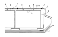
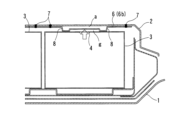
- FIG. 2 is a cross-sectional view showing the pressure release structure of the battery pack shown in FIG. 1, in which (a) is a state in which internal pressure is not applied, and (b) is a state in which internal pressure is applied.
- FIG. 3 is a cross-sectional view showing the pressure release structure of a battery pack shown as a reference, in which (a) shows a state in which no internal pressure is applied, and (b) shows a state in which internal pressure acts.
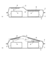
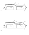
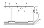
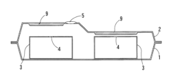
- a sectional view of essential parts of a second embodiment of the pressure release structure of a battery pack according to the present invention A sectional view of a main part of a third embodiment of a pressure release structure for a battery pack according to the present invention
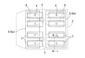
- this pressure release structure includes a lower case 1 and an upper case 2 provided so as to cover the lower case 1.
- FIGS. 1 to 3 A sealed space in which a battery module 3 is housed is formed between the lower case 1 and the upper case 2.
- the lower case 1 is a tray-shaped member that opens upward, and is adapted to accommodate a plurality of battery modules 3. Although its material is not particularly limited, in this embodiment it is made of a metal plate.
- the battery modules 3 are composed of lithium ion batteries, and each battery module 3 is placed vertically (with its long side in the direction along the front and rear of the vehicle).
- a discharge port 4 is formed on the top surface of the battery module 3 to release the internal pressure when the internal pressure of the battery module 3 increases.
- this embodiment shows eight rectangular parallelepiped battery modules 3 placed vertically, this is merely an example, and the orientation, shape, size, number, type of batteries, etc. of the battery modules 3 may be changed as appropriate. Is possible.
- the upper case 2 is a member that has almost the same shape as the lower case 1 in plan view.
- the material of the upper case 2 is not particularly limited, it is made of a metal plate in this embodiment.
- Two pressure release portions 5 are formed on the upper surface of the upper case 2 to release the internal pressure in the sealed space formed by the lower case 1 and the upper case 2 when the internal pressure increases.
- the pressure release portion 5 may be a valve that is closed when the internal pressure of the closed space is below a predetermined value and opens when the internal pressure exceeds a predetermined value.
- a heat shield plate 6 is provided on the back surface of the upper case 2 facing the closed space to suppress heat transfer from the battery module 3 housed in the closed space to the upper case 2.
- its material is not particularly limited, in this embodiment it is made of a metal plate.
- the heat shield plate 6 is fixed to the back surface of the upper case 2 by spot welds 7.
- This heat shield plate 6 is provided not on the entire back surface of the upper case 2 but on a portion thereof. That is, in this embodiment, two heat shield plates 6 are provided with a gap in the front-rear direction of the vehicle. The size of this gap is slightly larger than the size of the pressure release part 5 formed in the upper case 2.
- the rigidity of the upper case 2 can be made different such that the rigidity of the upper case 2 is high in the part where the heat shield plate 6 is provided and low in the part where the heat shield plate 6 is not provided. It's set.
- the pressure release portion 5 is formed in a portion of the upper case 2 that has low rigidity.
- the front heat shield plate 6 will be referred to as a front heat shield plate 6a
- the rear heat shield plate 6 will be referred to as a rear heat shield plate 6b.
- a plurality of gas guide portions 8 extending in the front-rear direction and protruding downward are formed on the lower surfaces of the front heat shield plate 6a and the rear heat shield plate 6b.
- the lower end of the gas guide section 8 faces the upper surface of the battery module 3.
- the rear end side of the gas guide part 8 formed on the front heat shield plate 6a and the front end side of the gas guide part 8 formed on the rear heat shield plate 6b are formed on the upper case 2. It is bent toward the pressure release part 5.
- two gas guide portions 8 are formed for each battery module 3 housed in a sealed space, and an exhaust port is formed in the battery module 3 between the two gas guide portions 8. 4 is located. That is, when gas is discharged from the discharge port 4 as the internal pressure of the battery module 3 increases, the gas is discharged by the upper surface of the battery module 3, the lower surface of the heat shield plate 6, and the two gas guide portions 8. It is guided to the pressure release part 5 using the enclosed gap g as a main passage.
- the upper case 2 is configured such that the rigidity is high in the region where the heat shield plate 6 is provided and low in the region where it is not provided, and the pressure release portion 5 is formed in the region with low rigidity. The points are the same.
- the heat shield plate 6 is fixed to the back surface of the upper case 2 using the spot welding part 7, but the fixing means is determined by taking into consideration the materials and shapes of the upper case 2 and the heat shield plate 6. , for example, can be modified as appropriate, such as fixing with screws.
- a heat shield plate 6 is partially provided on the back surface of the upper case 2, and the rigidity of the upper case 2 is high at the portion where the heat shield plate 6 is provided.
- gas is discharged from the discharge port 4 formed in the battery module 3 due to an abnormality in the battery module 3.
- the internal pressure of the battery pack increases.
- gas is released from the pressure release part 5 while deforming so that the periphery of the pressure release part 5, which has relatively low rigidity, is at the top.
- the shape after deformation (deformation mode) is controlled so that the upper case 2 deforms greatly when the internal pressure of the battery pack increases. This allows the internal pressure to be released quickly.
- the rigidity of the upper case 10 is The height increases over almost the entire area, including the area around the exposed area.
- the upper case 10 itself will be damaged due to its high rigidity, as shown in FIG. 5(b), for example. It tries to displace upward without deforming too much. Therefore, the internal pressure of the battery pack remains trapped, which is undesirable.
- FIG. 1 A second embodiment of the pressure release structure according to the present invention is shown in FIG.
- the pressure release structure according to the second embodiment is basically the same as the structure according to the first embodiment, but the heat shield plate 6 and the gas guide part 8 are composed of one member, and the upper case 2 and the The difference is that a heat insulating space a (air layer) that suppresses heat transfer from the battery module 3 to the upper case 2 is formed between the heat plate 6 and the heat plate 6 .
- the heat shield plate 6 and the gas guide portion 8 are formed by bending a single metal plate.
- the gas is surrounded by the upper surface of the battery module 3, the lower surface of the heat shield plate 6, and the two gas guide portions 8. It is guided to the pressure release part 5 (see FIG. 1 etc.) using the gap g as the main passage.
- the rigidity of the upper case 2 is high in the vicinity of the gas guide section 8, and is low in the region away from the gas guide section 8. . Therefore, similarly to the first embodiment, the shape after deformation (deformation mode) of the upper case 2 can be controlled so that the upper case 2 is greatly deformed when the internal pressure of the battery pack increases, and the internal pressure can be quickly reduced. Can be opened.
- the heat insulating space a is formed between the upper case 2 and the heat shield plate 6, even if the battery module 3 generates heat, the heat is not easily transmitted to the upper case 2. Do not overheat. Therefore, it is possible to prevent abnormalities caused by heat from occurring in the coating film or the like formed on the upper surface of the upper case 2.
- the thickness of the heat insulating space a can be determined as appropriate as long as the heat transfer from the battery module 3 to the upper case 2 can be suppressed to a predetermined value or less.
- FIG. 1 A third embodiment of the pressure release structure according to the present invention is shown in FIG.
- the pressure release structure according to the third embodiment is different from the structure of the first embodiment in that the gas guide portion 8 is directly formed on the back surface of the upper case 2.
- the gas guide portion 8 is directly formed on the back surface of the upper case 2.
- the gas guide portion 8 also acts as a reinforcing rib that reinforces the upper case 2, and the rigidity of the upper case 2 is high in the portion where the gas guide portion 8 is formed, and in the portion where the gas guide portion 8 is not formed. It's getting lower.
- a pressure release portion 5 is formed in a portion where the gas guide portion 8 is not formed. Therefore, similarly to each of the above embodiments, the shape after deformation (deformation mode) of the upper case 2 can be controlled so that the upper case 2 is greatly deformed when the internal pressure of the battery pack increases, and the internal pressure can be quickly reduced. can be opened to
- FIG. 1 A fourth embodiment of the pressure release structure according to the present invention is shown in FIG.
- the pressure release structure according to the fourth embodiment differs from the structure of the first embodiment in that a thick portion 9 is formed in a part of the upper case 2, which is thicker than other parts.
- the pressure release portion 5 is formed in a portion other than the thick wall portion 9.
- the material of this upper case 2 is not particularly limited, but it may be made of resin or the like whose thickness can be easily changed depending on the part. Further, the thick portion 9 can be formed at a desired location by a processing method such as die casting.
- the shape after deformation (deformation mode) of the upper case 2 can be controlled so that the upper case 2 is greatly deformed when the internal pressure of the battery pack increases, and the internal pressure can be quickly reduced. can be opened to
Landscapes
- Chemical & Material Sciences (AREA)
- Chemical Kinetics & Catalysis (AREA)
- Electrochemistry (AREA)
- General Chemical & Material Sciences (AREA)
- Engineering & Computer Science (AREA)
- Manufacturing & Machinery (AREA)
- Gas Exhaust Devices For Batteries (AREA)
- Battery Mounting, Suspending (AREA)
- Secondary Cells (AREA)
Priority Applications (1)
| Application Number | Priority Date | Filing Date | Title |
|---|---|---|---|
| JP2023544427A JP7568120B2 (ja) | 2022-03-24 | 2023-02-21 | 電池パックの圧力開放構造 |
Applications Claiming Priority (2)
| Application Number | Priority Date | Filing Date | Title |
|---|---|---|---|
| JP2022047796 | 2022-03-24 | ||
| JP2022-047796 | 2022-03-24 |
Publications (1)
| Publication Number | Publication Date |
|---|---|
| WO2023181751A1 true WO2023181751A1 (ja) | 2023-09-28 |
Family
ID=88101200
Family Applications (1)
| Application Number | Title | Priority Date | Filing Date |
|---|---|---|---|
| PCT/JP2023/006139 Ceased WO2023181751A1 (ja) | 2022-03-24 | 2023-02-21 | 電池パックの圧力開放構造 |
Country Status (2)
| Country | Link |
|---|---|
| JP (1) | JP7568120B2 (cg-RX-API-DMAC7.html) |
| WO (1) | WO2023181751A1 (cg-RX-API-DMAC7.html) |
Cited By (3)
| Publication number | Priority date | Publication date | Assignee | Title |
|---|---|---|---|---|
| JP2025519162A (ja) * | 2023-04-28 | 2025-06-24 | エルジー エナジー ソリューション リミテッド | バッテリーパック及びそれを含む自動車 |
| WO2025182985A1 (ja) * | 2024-02-28 | 2025-09-04 | 株式会社Aescジャパン | 電池モジュール及び電池パック |
| JP2026502191A (ja) * | 2023-11-07 | 2026-01-21 | エルジー エナジー ソリューション リミテッド | バッテリアセンブリおよびこれを含むバッテリパック |
Citations (6)
| Publication number | Priority date | Publication date | Assignee | Title |
|---|---|---|---|---|
| JP2017033886A (ja) * | 2015-08-06 | 2017-02-09 | 日産自動車株式会社 | バッテリパックの圧力開放機構 |
| CN207250603U (zh) * | 2017-09-05 | 2018-04-17 | 上海电巴新能源科技有限公司 | 电池箱壳体、电池箱以及电池箱总成 |
| CN110444835A (zh) * | 2019-08-29 | 2019-11-12 | 蜂巢能源科技有限公司 | 电池包和车辆 |
| JP2019197622A (ja) * | 2018-05-08 | 2019-11-14 | トヨタ自動車株式会社 | 電池パック |
| CN210349894U (zh) * | 2019-05-13 | 2020-04-17 | 南京天河汽车零部件股份有限公司 | 一种智能控制的新能源汽车电池箱总成 |
| CN111430840A (zh) * | 2020-03-31 | 2020-07-17 | 蜂巢能源科技有限公司 | 延缓动力电池包热扩散的控制方法和控制系统 |
-
2023
- 2023-02-21 JP JP2023544427A patent/JP7568120B2/ja active Active
- 2023-02-21 WO PCT/JP2023/006139 patent/WO2023181751A1/ja not_active Ceased
Patent Citations (6)
| Publication number | Priority date | Publication date | Assignee | Title |
|---|---|---|---|---|
| JP2017033886A (ja) * | 2015-08-06 | 2017-02-09 | 日産自動車株式会社 | バッテリパックの圧力開放機構 |
| CN207250603U (zh) * | 2017-09-05 | 2018-04-17 | 上海电巴新能源科技有限公司 | 电池箱壳体、电池箱以及电池箱总成 |
| JP2019197622A (ja) * | 2018-05-08 | 2019-11-14 | トヨタ自動車株式会社 | 電池パック |
| CN210349894U (zh) * | 2019-05-13 | 2020-04-17 | 南京天河汽车零部件股份有限公司 | 一种智能控制的新能源汽车电池箱总成 |
| CN110444835A (zh) * | 2019-08-29 | 2019-11-12 | 蜂巢能源科技有限公司 | 电池包和车辆 |
| CN111430840A (zh) * | 2020-03-31 | 2020-07-17 | 蜂巢能源科技有限公司 | 延缓动力电池包热扩散的控制方法和控制系统 |
Cited By (3)
| Publication number | Priority date | Publication date | Assignee | Title |
|---|---|---|---|---|
| JP2025519162A (ja) * | 2023-04-28 | 2025-06-24 | エルジー エナジー ソリューション リミテッド | バッテリーパック及びそれを含む自動車 |
| JP2026502191A (ja) * | 2023-11-07 | 2026-01-21 | エルジー エナジー ソリューション リミテッド | バッテリアセンブリおよびこれを含むバッテリパック |
| WO2025182985A1 (ja) * | 2024-02-28 | 2025-09-04 | 株式会社Aescジャパン | 電池モジュール及び電池パック |
Also Published As
| Publication number | Publication date |
|---|---|
| JPWO2023181751A1 (cg-RX-API-DMAC7.html) | 2023-09-28 |
| JP7568120B2 (ja) | 2024-10-16 |
Similar Documents
| Publication | Publication Date | Title |
|---|---|---|
| JP7568120B2 (ja) | 電池パックの圧力開放構造 | |
| CN115968517B (zh) | 电池模块以及包括该电池模块的电池组和车辆 | |
| EP1921691B1 (en) | Battery module | |
| KR102885424B1 (ko) | 인근 모듈로의 가스 이동을 방지할 수 있는 전지 모듈 | |
| KR20260045730A (ko) | 배터리 팩 및 이를 포함하는 자동차 | |
| JP2023537523A (ja) | 電池モジュールおよびそれを含む電池パック | |
| EP4096008B1 (en) | Battery pack and device including same | |
| EP3926734B1 (en) | Battery module and battery pack including the esame | |
| JP2021007090A (ja) | 電池パック及び車両 | |
| KR102481152B1 (ko) | 차량용 경량 배터리 케이스 | |
| EP4084197A1 (en) | Battery pack and device including same | |
| JP7757525B2 (ja) | バッテリーパック及びこれを含む自動車 | |
| US20240079716A1 (en) | Traction battery pack venting assembly and method of establishing a traction battery pack vent path | |
| EP4435955A1 (en) | Battery pack | |
| WO2018221002A1 (ja) | 車両搭載用の電池パック | |
| KR20240012283A (ko) | 배터리 셀 블럭 및, 이를 포함하는 배터리 팩 및 자동차 | |
| EP4220831A1 (en) | Battery module and battery pack including same | |
| JP2021174588A (ja) | 蓄電セルおよび蓄電装置 | |
| JP2025519162A (ja) | バッテリーパック及びそれを含む自動車 | |
| KR20240098779A (ko) | 열 전파 지연에 효과적인 배터리 팩 | |
| JP7744512B2 (ja) | バッテリーセルブロック及びこれを含むバッテリーパック、並びに自動車 | |
| JP7768198B2 (ja) | 電池パック | |
| KR102951911B1 (ko) | 배터리 팩 및 이를 포함하는 자동차 | |
| JP7652180B2 (ja) | 蓄電装置 | |
| EP4525143B1 (en) | Battery cell assembly and battery pack including the same |
Legal Events
| Date | Code | Title | Description |
|---|---|---|---|
| WWE | Wipo information: entry into national phase |
Ref document number: 2023544427 Country of ref document: JP |
|
| 121 | Ep: the epo has been informed by wipo that ep was designated in this application |
Ref document number: 23774350 Country of ref document: EP Kind code of ref document: A1 |
|
| NENP | Non-entry into the national phase |
Ref country code: DE |
|
| 122 | Ep: pct application non-entry in european phase |
Ref document number: 23774350 Country of ref document: EP Kind code of ref document: A1 |