WO2023181647A1 - 時計およびバンド - Google Patents
時計およびバンド Download PDFInfo
- Publication number
- WO2023181647A1 WO2023181647A1 PCT/JP2023/003064 JP2023003064W WO2023181647A1 WO 2023181647 A1 WO2023181647 A1 WO 2023181647A1 JP 2023003064 W JP2023003064 W JP 2023003064W WO 2023181647 A1 WO2023181647 A1 WO 2023181647A1
- Authority
- WO
- WIPO (PCT)
- Prior art keywords
- pin
- cover member
- groove
- band
- connecting piece
- Prior art date
- Legal status (The legal status is an assumption and is not a legal conclusion. Google has not performed a legal analysis and makes no representation as to the accuracy of the status listed.)
- Ceased
Links
Images



Classifications
-
- A—HUMAN NECESSITIES
- A44—HABERDASHERY; JEWELLERY
- A44C—PERSONAL ADORNMENTS, e.g. JEWELLERY; COINS
- A44C5/00—Bracelets; Wrist-watch straps; Fastenings for bracelets or wrist-watch straps
- A44C5/14—Bracelets; Wrist-watch straps; Fastenings for bracelets or wrist-watch straps characterised by the way of fastening to a wrist-watch or the like
- A44C5/147—Watchcase itself used as fastener
-
- A—HUMAN NECESSITIES
- A44—HABERDASHERY; JEWELLERY
- A44C—PERSONAL ADORNMENTS, e.g. JEWELLERY; COINS
- A44C5/00—Bracelets; Wrist-watch straps; Fastenings for bracelets or wrist-watch straps
- A44C5/14—Bracelets; Wrist-watch straps; Fastenings for bracelets or wrist-watch straps characterised by the way of fastening to a wrist-watch or the like
Definitions
- the present invention relates to a watch and a band.
- both ends of a pin also called a spring rod, housed in a connecting piece placed at the end of the band, are held in hole holes formed in the band attachment part of the watch's exterior case.
- the band is connected to the outer case.
- the pin includes a spring and a pair of sliding bodies placed at both ends of the spring and pressed by the springs, and can be expanded and contracted by pressing the sliding bodies against the spring.
- a user who wants to replace the band removes the band from the outer case by shortening the pin and removing both ends from the ring holes.
- Patent Document 1 describes a pin in which a slider is formed with a knob that can be operated from the outside. A user replacing the band can easily shorten the pin by pulling the knob toward the center of the pin.
- the watch and band according to the embodiments improve maintainability and prevent deterioration in appearance quality in a watch whose band can be replaced.
- the watch according to the embodiment includes an exterior case having a pair of band attachment parts in which insertion holes are formed so as to face each other, and ends on both sides inserted into the insertion holes of the pair of band attachment parts.
- a connecting piece that has a pin held in the band attachment part and a groove placed at one end of the band and formed on the bottom, and the groove connects the band to the exterior case by accommodating the pin held in the band attachment part.
- a cover member that covers a groove in which the pin is housed, and the pin has an elastic body that presses the end so that the end can move in parallel in the axial direction.
- An operation part is formed on the side surface of the cover member to receive an operation for moving the end part in parallel toward the center of the pin so that the pin can be removed from the band attachment part.
- the position facing the operating section is opened so that the operating section can be operated from the outside in the state.
- the cover member covers the entire groove in the extending direction, and that the cover member has an opening formed at a position facing the operating section.
- the operating section protrudes from the opening to the outside of the cover member.
- the pin is accommodated in the groove so as to be rotatable in the circumferential direction
- the opening is formed with a notch in the rotational direction of the pin
- the cover member is configured such that the operating portion is located in the notch. It is preferable to restrict the operation of shortening the pin with respect to the operating portion in the state where the pin is located.
- the pin is accommodated in the groove so as to be rotatable in the circumferential direction
- the opening is formed with a notch in the rotational direction of the pin
- the cover member is configured such that the operating portion is located in the notch. It is preferable to restrict the pin from expanding from the shortened state in the housed state.
- the cover member is formed separately from the connecting piece, and has an extending portion extending to a side surface of the connecting piece, and the extending portion has a pin housed in the groove. It is preferable that an insertion hole is formed, and the cover member is held by the connecting piece while covering the groove by inserting a pin into the insertion hole.
- the cover member is coupled to the connecting piece and covers a portion of the groove in the extending direction so as to prevent the pin housed in the groove from falling off.
- the band according to the embodiment includes a pin that is held in the band attachment part by inserting both ends into insertion holes formed in a pair of band attachment parts of the exterior case, and a pin that is arranged at one end of the band and has a bottom surface.
- a connecting piece having a groove formed therein, the connecting piece connecting the band to the exterior case by accommodating the pin held in the band attachment part; and a cover member covering the groove in which the pin is housed;
- the pin has an elastic body that presses the end so that the end can be moved in parallel in the axial direction, and a side surface of the pin has an elastic body that presses the end so that the end can be moved in parallel in the axial direction.
- an operating section is formed that accepts an operation of moving the end portion in parallel toward the center of the pin, and the cover member is attached to the operating section so that the operating section can be operated from the outside with the pin housed in the groove. Open the opposing position.
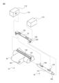
- FIG. 1 is a perspective view of a timepiece 1.
- FIG. 3 is an exploded perspective view showing the connection relationship between the band attachment part 112 and the connection piece 13.
- FIG. 3 is a perspective view of the connecting piece 13.
- FIG. 3 is a sectional view of the connecting piece 13.
- FIG. 2 is a perspective view of a connecting piece 23; 3 is a perspective view of a connecting piece 33.
- FIG. FIG. 4 is a perspective view of a connecting piece 43;
- FIG. 4 is a cross-sectional view of a connecting piece 43.
- FIG. 1 is a perspective view of a watch 1 according to an embodiment.
- the watch 1 includes a main body 11, a pair of bands 12, and the like.
- the main body 11 is a mechanical watch, a quartz watch, or the like having a timekeeping function.
- the main body 11 includes a pointer, a dial, a movement, etc., and an outer case 111 containing them.
- the exterior case 111 has a pair of band attachment parts 112 on the 12 o'clock side and the 6 o'clock side, respectively, to which bands are attached.
- the pair of bands 12 are formed by connecting a plurality of pieces arranged in a predetermined direction.
- a connecting piece 13 also called an end piece, a tip piece, or a bow tube, which connects the band 12 to the exterior case 111, is arranged.
- One ends of the pair of bands 12 are connected to band attachment portions 112 on the 12 o'clock side and the 6 o'clock side of the exterior case 111 via connection pieces 13, respectively.
- the other ends of the pair of bands 12 are connected to each other via a clasp (not shown), and the band 12 is formed into an annular shape.
- a user wears the watch 1 by passing his or her wrist through the ring-shaped band 12.
- FIG. 2 is an exploded perspective view showing the connection structure between the connecting piece 13 and the band attachment part 112
- FIG. 3 is a perspective view of the connecting piece 13
- FIG. 4 is a state in which the band 12 is attached to the band attachment part 112. It is a sectional view of connection piece 13 in . 2 to 4 are illustrated with the bottom surface (lower surface in FIG. 1) of the connecting piece 13 facing upward.
- FIG. 4 is a sectional view taken along the line IV-IV in FIG. 3.
- the pair of band attachment parts 112 are formed with insertion holes 113, also called ring holes, so as to face each other.
- the pin 14 is held in the band attachment part 112 by having both ends inserted into the pair of insertion holes 113, respectively.
- the connecting piece 13 connects the band 12 to the exterior case 111 by accommodating the pin 14 held by the band attaching part 112 in a groove 131 on the bottom surface.
- the cover member 15 covers the groove 131 in which the pin 14 is accommodated.
- the pin 14 includes a cylindrical body 141, an elastic body 142 built into the cylindrical body 141, and an axis of the cylindrical body 141. It has a pair of sliding bodies 143 that can be moved in parallel in the direction.
- the cylindrical body 141 is formed into a cylindrical shape.
- First openings 144 are formed in both end surfaces of the cylindrical body 141, respectively.
- a pair of second openings 145 extending in the axial direction are formed on the side surface of the cylindrical body 141 .
- Each of the sliding bodies 143 is formed with an end portion 146 that projects from the first opening 144 to the outside of the cylindrical body 141 .
- the pin 14 is held in the band attachment part 112 by inserting the ends 146 of the pin 14 into the insertion holes 113 of the band attachment part 112.
- the elastic body 142 is a coil spring.
- the elastic body 142 contacts a pair of sliding bodies 143 at both ends, and presses the sliding bodies 143 so that the end portions 146 can move in parallel in the axial direction.
- each of the sliding bodies 143 is formed with an operating portion 147 that protrudes from the second opening 145 to the outside of the cylindrical body 141 . By pulling the operating portions 147 toward the center of the pin 14 in the axial direction, the end portion 146 is moved in parallel toward the center of the pin 14, shortening the pin 14, and removing the pin 14 from the band attachment portion 112. It becomes possible.
- a groove 131 (see FIG. 2) for accommodating the pin 14 is formed on the bottom surface of the connecting piece 13.
- the groove portion 131 extends from one end of the bottom surface of the connecting piece 13 in the axial direction of the pin 14 to the other end so that the pin 14 can be inserted from the side surface of the connecting piece 13.
- the groove portion 131 is formed so that its maximum width is the same as the outer diameter of the cylindrical body 141 of the pin 14 or slightly larger than the outer diameter of the cylindrical body 141.
- a narrow portion 132 is formed at the connection portion between the groove portion 131 and the bottom surface of the connecting piece 13 so that the width of the groove portion 131 is partially smaller than the outer diameter of the cylindrical body 141. Thereby, the pin 14 is accommodated in the groove 131 without falling off.
- the operating portion 147 extends from between the narrowed portions 132 and can be operated from the outside. Further, since the cylindrical body 141 is formed in a cylindrical shape, the pin 14 can rotate in the circumferential direction while being accommodated in the groove 131 within a range where the operating portion 147 does not come into contact with the narrowed portion 132.
- the cover member 15 is a member that covers the groove portion 131, and is formed separately from the connection piece 13.
- the cover member 15 is a flat member extending in the extending direction of the groove 131 so as to cover the groove 131 from one end to the other end in the extending direction, that is, to cover the entire groove 131 in the extending direction.
- the cover member 15 opens a position facing the operating portion 147 so that the operating portion 147 can be operated from the outside with the groove portion 131 covered by the cover member 15.
- rectangular openings 151 extending in the sliding direction of the operating section 147 are formed in positions facing the operating section 147 of the cover member 15, so that the operating section 147 The opposing position is open, and the operating section 147 can be operated from the outside.
- the operating portion 147 is formed to have such a length that it protrudes from the opening 151 to the outside of the cover member 15 while the groove portion 131 in which the pin 14 is accommodated is covered by the cover member 15. This allows the user to grasp and operate the portion of the operating section 147 that protrudes from the cover member 15 with his or her fingers.
- the cover member 15 has extending portions 152 at both ends in the extending direction that extend to the side surfaces of the connecting piece 13 so as to cover both ends of the groove portion 131.
- the extension portion 152 is formed with an insertion hole 153 through which the end portion 146 of the pin 14 accommodated in the groove portion 131 is inserted. By inserting the end portion 146 into the insertion hole 153, the cover member 15 is held by the connecting piece 13 while covering the groove portion 131.
- the narrowed portion 132 of the groove portion 131 is recessed by a distance corresponding to the thickness of the cover member 15 with respect to the bottom and side surfaces of the connecting piece 13.
- a connecting portion 16 that connects the connecting piece 13 with a piece of the band 12 is formed at the end of the connecting piece 13 on the band 12 side.
- the connecting portion 16 has a through hole 161 passing through a pair of side surfaces. With a connecting pin (not shown) inserted into the through hole 161, both ends of the connecting pin are held by pieces of the band 12, thereby connecting the connecting piece 13 with the band 12.
- the pin 14 When attaching the band 12 to the exterior case 111, the pin 14 is first accommodated in the groove 131.
- the pin 14 is accommodated in the groove 131 of the connecting piece 13 from the side surface of the connecting piece 13 connected to the band 12 .
- the cover member 15 is placed so as to cover the groove 131 in which the pin 14 is accommodated.
- the cover member 15 is placed above the groove 131 so that the tip of the operating section 147 protrudes from the opening 151 when the operating section 147 is not operated.
- the tip of the extending portion 152 interferes with the end portion 146 of the pin 14, both ends of the groove portion 131 are not covered by the extending portion 152 and are open.
- the user grasps the tips of the operating parts 147 protruding from the opening 151 and draws the operating parts 147 toward each other.
- the pin 14 is shortened until the tip of the end portion 146 is located inside the extension portion 152 in the axial direction, and the tip of the extension portion 152 no longer interferes with the end portion 146.
- the extending portion 152 is inserted to a position covering both ends of the groove portion 131. Thereby, the groove portion 131 is covered by the cover member 15.
- the cover member 15 After the groove portion 131 is covered by the cover member 15, the user releases the operating portion 147. As a result, the pin 14 is extended, and the end portion 146 is inserted into the insertion hole 153. In this way, the cover member 15 is held on the connecting piece 13 while covering the groove portion 131.
- the connecting piece 13 is connected to the band attachment part 112.
- the user grasps the operation parts 147 and pulls them toward each other.
- the pin is shortened until the tip of the end portion 146 is located inside the extension portion 152.
- the connecting piece 13 is placed between the pair of band attachment parts 112 of the exterior case 111.
- the pin 14 expands, and the end portion 146 is inserted into the insertion hole 153 and inserted into the insertion hole 113 of the band attachment portion 112. In this way, the pin 14 is held by the band attachment part 112, and the band 12 is attached to the outer case 111.
- the user grasps the operating parts 147 and pulls them toward each other. As a result, the pin 14 is shortened until the tip of the end portion 146 comes out of the insertion hole 113. In this state, the connecting piece 13 is removed from between the band attachment parts 112, and the band 12 is removed from the outer case 111.
- the user releases the operating part 147.
- the pin 14 expands and the end portion 146 is inserted into the insertion hole 153 again.
- the cover member 15 is held on the connecting piece 13 while covering the groove 131. Therefore, even when the band 12 is not attached to the outer case 111, the pin 14 is prevented from falling out of the groove 131, and the possibility of losing the pin 14 is reduced.
- the cover member 15 is removed first.
- the user grasps the tips of the operating parts 147 and pulls them toward each other.
- the pin is shortened until the tip of the end portion 146 is located inside the extension portion 152.
- the cover member 15 is pulled up until the insertion hole 153 moves to a position where it does not oppose the end portion 146 of the pin 14.
- the user releases the tip of the operating section 147 to release the operation on the operating section 147.
- the cover member 15 is further pulled up and removed from the groove portion 131. In this way, the cover member 15 is removed from the connecting piece 13.
- the pin 14 is removed from the groove 131.
- the pin 14 is removed by being pulled out laterally from the groove 131. In this way, the pin 14 can be easily removed from the connecting piece 13 without using a special tool, so even if the pin 14 is damaged, it can be easily replaced, improving maintainability.
- the watch 1 includes the outer case 111, the pin 14, the connecting piece 13, and the cover member 15.
- the exterior case 111 has a pair of band attachment parts 112 in which insertion holes 113 are formed so as to face each other.
- the pin 14 is formed to be expandable and retractable by a built-in elastic body 142, and is held by the band attachment portions 112 by having both ends inserted into the insertion holes 113 of the pair of band attachment portions 112, respectively.
- the connecting piece 13 is arranged at one end of the band 12, and a groove 131 is formed on the bottom surface.
- the connecting piece 13 connects the band 12 to the exterior case 111 by accommodating the pin 14 held by the band attaching part 112 in the groove part 131 .
- an operating portion 147 is formed on the side surface of the pin 14 to accept an operation for shortening the pin 14 so that the pin 14 can be removed from the band attachment portion 112.
- the cover member 15 has a position facing the operating section 147 open so that the operating section 147 can be operated from the outside with the pin 14 housed in the groove 131.
- the watch 1 is a watch with a replaceable band that can improve maintainability and prevent deterioration in appearance quality.
- the cover member 15 covers the entire groove portion 131 in the extending direction.
- An opening is formed in the cover member 15 at a position facing the operating section 147. As a result, the entire groove portion 131 is no longer visible from below, improving the appearance quality.
- the operating portion 147 protrudes from the opening 151 to the outside of the cover member 15. This allows the user to grasp and operate the operating section 147 with his or her fingers, making it easier to remove the band 12.
- the cover member 15 is formed separately from the connection piece 13 and has an extension portion 152 that extends to the side surface of the connection piece 13.
- the extending portion 152 is formed with an insertion hole 153 into which the pin 14 accommodated in the groove portion 131 is inserted.
- the cover member 15 is held by the connecting piece 13 while covering the groove portion 131 by inserting the pin 14 into the insertion hole 153 . Thereby, the groove portion 131 is no longer visible from the side, and the appearance quality is further improved.
- the operating portion 147 was assumed to protrude from the opening 151 to the outside of the cover member 15, but the present invention is not limited to such an example.
- the operating portion 147 may be formed in such a length that it does not protrude outside the cover member 15. That is, the operating portion 147 may be formed shorter than the distance between the pin 14 and the opening 151 of the cover member 15.
- the user can insert a tool such as tweezers into the opening 151 to operate the operating section 147 and remove the band 12.
- the operating section 147 is less likely to be visually recognized from the outside, so that the appearance quality is further improved.
- FIG. 5 is a perspective view of a connecting piece 23 of a watch according to another embodiment.
- the connection piece 23 differs from the connection piece 13 in that it has a cover member 25 instead of the cover member 15.
- the cover member 25 differs from the cover member 15 in that an opening 251 is formed instead of the opening 151.
- the other configurations of the cover member 25 are the same as the corresponding configurations of the cover member 15, so the same reference numerals are given and the explanation will be omitted.
- the opening 251 is formed in a rectangular shape extending in the sliding direction of the operating section 147, and a notch 254 is formed at the position of the operating section 147 when it is not operated.
- the cutout portion 254 is formed in a direction perpendicular to the rotating direction of the pin 14 accommodated in the groove portion 131, that is, the extending direction of the pin 14.
- the cutout portion 254 is formed in the same direction for each of the plurality of openings 251.
- the operating portion 147 when not being operated, the operating portion 147 is located at the outer end of the rectangle of the opening 251 in the axial direction of the pin 14. Therefore, the notch 254 is formed at the outer end of the rectangle, and the opening 251 is formed in an L shape.
- the user rotates the pin 14 housed in the groove 131 in the circumferential direction (direction A in FIG. 5).
- the operating section 147 is accommodated in the notch 254.
- the operating portion 147 accommodated in the notch 254 interferes with the cover member 25 and cannot move toward the center of the pin 14 in the axial direction. That is, the cover member 25 restricts the operation of shortening the pin 14 by drawing the operating parts 147 toward each other when the operating parts 147 are housed in the notch 254 .
- the pin 14 is accommodated in the groove 131 so as to be rotatable in the circumferential direction.
- a notch 254 is formed in the opening 251 of the cover member 25 in the direction in which the pin 14 rotates.
- the cover member 25 restricts the operation of shortening the pin 14 relative to the operating portion 147 when the operating portion 147 is housed in the notch 254 . This prevents the band 12 from detaching from the outer case 111 due to the operation of the operating section 147 while the user is using the watch 1.
- FIG. 6 is a perspective view of a connecting piece 33 of a timepiece according to another embodiment.
- the connection piece 33 differs from the connection piece 13 in that it has a cover member 35 instead of the cover member 15.
- the cover member 35 differs from the cover member 15 in that an opening 351 is formed instead of the opening 151.
- the other configurations of the cover member 35 are the same as the corresponding configurations of the cover member 15, so the same reference numerals are given and the explanation will be omitted.
- the opening 351 is formed in a rectangular shape extending in the sliding direction of the operating section 147, and a notch 354 is formed at the position of the operating section 147 when the pin 14 is shortened.
- the cutout portion 354 is formed in a direction perpendicular to the rotating direction of the pin 14 accommodated in the groove portion 131, that is, the extending direction of the pin 14.
- the cutout portion 354 is formed in the same direction for each of the plurality of openings 351.
- the notch 354 is formed at the inner end of the rectangle, which is the position when the pin 14 is shortened, and the opening 351 is formed in an L-shape.
- the user grasps the tips of the operating parts 147 protruding from the opening 351, draws the operating parts 147 toward each other, and rotates the pin 14 in the circumferential direction A.
- the end portion 146 moves in parallel toward the center in the axial direction until the tip of the end portion 146 is located inside the extension portion 152, and the pin 14 is shortened. be accommodated in.
- the operating section 147 accommodated in the notch 354 interferes with the cover member 35 and cannot move toward the outside in the axial direction of the pin 14 .
- the cover member 35 prevents the pin 14 from expanding in a state where the operating portion 147 is accommodated in the notch 354. Therefore, even if the user removes his/her hand from the operating section 147, the pin 14 remains in the shortened state.
- the extending portion 152 of the cover member 35 is inserted to a position covering both ends of the groove portion 131.
- the groove portion 131 is covered by the cover member 35.
- the cover member 35 can be easily attached.
- the connecting piece 33 is connected to the band attaching part 112
- the connecting piece 13 is placed between the pair of band attaching parts 112 of the exterior case 111 while the operating part 147 is housed in the notch 354. Ru.
- the user rotates the pin 14 in the circumferential direction B.
- the operating portion 147 is detached from the cutout portion 354, and the end portion 146 is translated in a direction away from the center of the pin 14 in the axial direction and is inserted into the insertion hole 153. inserted into.
- the pin 14 is held by the band attachment part 112, and the band 12 is attached to the band attachment part 112.
- the pin 14 is accommodated in the groove 131 so as to be rotatable in the circumferential direction.
- a notch 354 is formed in the opening 351 of the cover member 35 in the direction in which the pin 14 rotates.
- the cover member 35 restricts the pin 14 from expanding in a state where the operating portion 147 is housed in the notch 354. This allows the pin 14 to maintain its shortened state even if the user takes his hand off the operating section 147, making it easier to replace the band.
- cutouts may be formed at both the position of the operating part 147 when it is not operated and the position of the operating part 147 when the pin 14 is shortened.
- the shapes of the openings are not limited to the examples of the openings 151, 251, and 351 described above.
- the cover member may be formed with an opening having any shape, such as an oval shape or a cross shape, which allows the operating portion 147 to be operated from the outside.
- FIG. 7 is a perspective view of a connecting piece 43 of a timepiece according to another embodiment
- FIG. 8 is a sectional view of the connecting piece 43.
- FIG. 8 is a cross-sectional view similar to FIG. 4.
- the connecting piece 43 differs from the connecting piece 13 in that it has a pin 44 and a cover member 45 instead of the pin 14 and the cover member 15.
- the other configurations of the connecting piece 43 are similar to the corresponding configurations of the connecting piece 13, so the same reference numerals are given and the explanation will be omitted.
- the pin 44 includes a cylindrical body 141, an elastic body 142 built into the cylindrical body 141, a first sliding body 443, and a second sliding body 448.
- the first sliding body 443 contacts one end of the elastic body 142.
- the first sliding body 443 is formed with an end portion 146 that projects from the first opening 144 to the outside of the cylindrical body 141, and also extends from the second opening 145 to the outside of the cylindrical body 141.
- a protruding operating portion 147 is formed.
- the second sliding body 448 abuts the other end of the elastic body 142.
- the second sliding body 448 is formed with an end portion 146 that projects from the first opening 144 to the outside of the cylindrical body 141 , and a recessed portion 449 is formed so as to face the second opening 145 .
- the operating section 447 fits into the recess 449.
- the recessed portion 449 and the operating portion 447 are fitted together by screwing together using a screw structure.
- the cover member 45 is formed coupled to the connecting piece 43. In the example shown in FIG. 7, the cover member 45 is formed integrally with the connection piece 43. The cover member 45 covers a portion of the groove portion 131 in the extending direction. In the example shown in FIGS. 7 and 8, the cover member 45 covers the space between the operating portion 147 and the operating portion 447 of the groove portion 131, leaving the positions of the operating portion 147 and the operating portion 447 open.
- the operating portion 147 is formed to have a length such that the upper end of the operating portion 147 is higher than the lower end of the cover member 45 when the pin 14 is housed in the groove 131.
- the operating portion 447 is formed to a length such that the upper end of the operating portion 447 is higher than the lower end of the cover member 45 when the pin 14 is accommodated in the groove 131 and the operating portion 447 is fitted into the recess 449. Ru.
- the operating portion 147 or 447 interferes with the cover member 45, so that the pin 14 is prevented from falling out of the groove 131.
- the pin 44 with the operation part 447 removed is accommodated in the groove 131 of the connection piece 43 from the side surface of the connection piece 43.
- the pin 44 is accommodated in the groove 131 from the side where the second sliding body 448 is disposed, as shown in direction C in FIG.
- the operating portion 447 is fitted into the recess 449.
- the operating parts 147 and 447 are operated to shorten the pin 44, and the connecting piece 43 is placed between the pair of band attachment parts 112 of the exterior case 111. .
- the cover member 45 is coupled to the connecting piece 43 and covers a portion of the groove 131 in the extending direction so as to prevent the pin 44 housed in the groove 131 from falling out of the groove 131. This eliminates the need to use a separate cover member, so the appearance quality is improved with a reduced number of parts, and the pin 44 is prevented from falling out of the groove 131.
- the operating portion 447 is fitted into the recessed portion 449 by screwing, but the present invention is not limited to such an example.
- the operating portion 447 may be fitted into the recess 449 via adhesive, adhesive tape, or the like.
- cover member 45 is formed integrally with the connecting piece 43, but the present invention is not limited to such an example.
- Cover member 45 may be coupled to cover member 45 in any manner such that it cannot be removed by a user.
- the cover member 45 may be bonded to the connecting piece 43 using an adhesive, adhesive tape, or the like.
Landscapes
- Electric Clocks (AREA)
- Purses, Travelling Bags, Baskets, Or Suitcases (AREA)
Priority Applications (3)
| Application Number | Priority Date | Filing Date | Title |
|---|---|---|---|
| JP2024509809A JPWO2023181647A1 (https=) | 2022-03-25 | 2023-01-31 | |
| US18/847,247 US20250194757A1 (en) | 2022-03-25 | 2023-01-31 | Watch and strap |
| CN202380028541.2A CN118900649A (zh) | 2022-03-25 | 2023-01-31 | 钟表及表带 |
Applications Claiming Priority (2)
| Application Number | Priority Date | Filing Date | Title |
|---|---|---|---|
| JP2022050718 | 2022-03-25 | ||
| JP2022-050718 | 2022-03-25 |
Publications (1)
| Publication Number | Publication Date |
|---|---|
| WO2023181647A1 true WO2023181647A1 (ja) | 2023-09-28 |
Family
ID=88101083
Family Applications (1)
| Application Number | Title | Priority Date | Filing Date |
|---|---|---|---|
| PCT/JP2023/003064 Ceased WO2023181647A1 (ja) | 2022-03-25 | 2023-01-31 | 時計およびバンド |
Country Status (4)
| Country | Link |
|---|---|
| US (1) | US20250194757A1 (https=) |
| JP (1) | JPWO2023181647A1 (https=) |
| CN (1) | CN118900649A (https=) |
| WO (1) | WO2023181647A1 (https=) |
Families Citing this family (2)
| Publication number | Priority date | Publication date | Assignee | Title |
|---|---|---|---|---|
| EP4473863A1 (fr) * | 2023-06-06 | 2024-12-11 | Harry Winston SA | Dispositif de boucle interchangeable |
| USD1111904S1 (en) * | 2024-08-26 | 2026-02-10 | Huade Chen | Watch strap connector |
Citations (8)
| Publication number | Priority date | Publication date | Assignee | Title |
|---|---|---|---|---|
| JPS59130518U (ja) * | 1983-02-23 | 1984-09-01 | 真志田 亨 | バネ棒 |
| JPS6077410U (ja) * | 1983-11-01 | 1985-05-30 | シチズン時計株式会社 | 時計バンドの中留構造 |
| US4564308A (en) * | 1982-03-08 | 1986-01-14 | Tooru Mashida | Spring rod for strap |
| JP3049000U (ja) * | 1997-11-18 | 1998-05-29 | 株式会社バンビ | ばね棒付きバンド |
| JPH11146804A (ja) * | 1997-11-18 | 1999-06-02 | Bambi:Kk | ばね棒付きバンド |
| JP2004187978A (ja) * | 2002-12-12 | 2004-07-08 | Citizen Watch Co Ltd | 帯状装身具 |
| JP2005349013A (ja) * | 2004-06-11 | 2005-12-22 | Seiko Epson Corp | 中留具、帯状体、および時計 |
| JP2015112442A (ja) * | 2013-12-16 | 2015-06-22 | カシオ計算機株式会社 | バンド取付構造および腕時計 |
-
2023
- 2023-01-31 CN CN202380028541.2A patent/CN118900649A/zh active Pending
- 2023-01-31 WO PCT/JP2023/003064 patent/WO2023181647A1/ja not_active Ceased
- 2023-01-31 US US18/847,247 patent/US20250194757A1/en active Pending
- 2023-01-31 JP JP2024509809A patent/JPWO2023181647A1/ja active Pending
Patent Citations (8)
| Publication number | Priority date | Publication date | Assignee | Title |
|---|---|---|---|---|
| US4564308A (en) * | 1982-03-08 | 1986-01-14 | Tooru Mashida | Spring rod for strap |
| JPS59130518U (ja) * | 1983-02-23 | 1984-09-01 | 真志田 亨 | バネ棒 |
| JPS6077410U (ja) * | 1983-11-01 | 1985-05-30 | シチズン時計株式会社 | 時計バンドの中留構造 |
| JP3049000U (ja) * | 1997-11-18 | 1998-05-29 | 株式会社バンビ | ばね棒付きバンド |
| JPH11146804A (ja) * | 1997-11-18 | 1999-06-02 | Bambi:Kk | ばね棒付きバンド |
| JP2004187978A (ja) * | 2002-12-12 | 2004-07-08 | Citizen Watch Co Ltd | 帯状装身具 |
| JP2005349013A (ja) * | 2004-06-11 | 2005-12-22 | Seiko Epson Corp | 中留具、帯状体、および時計 |
| JP2015112442A (ja) * | 2013-12-16 | 2015-06-22 | カシオ計算機株式会社 | バンド取付構造および腕時計 |
Also Published As
| Publication number | Publication date |
|---|---|
| US20250194757A1 (en) | 2025-06-19 |
| CN118900649A (zh) | 2024-11-05 |
| JPWO2023181647A1 (https=) | 2023-09-28 |
Similar Documents
| Publication | Publication Date | Title |
|---|---|---|
| WO2023181647A1 (ja) | 時計およびバンド | |
| JP6688362B2 (ja) | ブレスレットを取り付けるための装置 | |
| JP2504142Y2 (ja) | 取外し自在なバンド付時計 | |
| US11464301B2 (en) | Device for attaching a bracelet | |
| TWI524860B (zh) | 具有可更換腕帶或皮帶的可攜式物體 | |
| US11853011B2 (en) | Watch case provided with an annular ring, and a wristwatch and a wristwatch assembly kit comprising the same | |
| CN111134428A (zh) | 表带以及腕戴式设备 | |
| US11419395B2 (en) | Band and watch | |
| JP7358763B2 (ja) | バンドおよび時計 | |
| CN110389522B (zh) | 用于将表带固定在手表上的杆装置和手表 | |
| JP4473020B2 (ja) | 腕時計 | |
| JPH07303506A (ja) | 時計バンドの取り付け構造 | |
| CN114515051A (zh) | 连结体、带状件以及钟表 | |
| JP4754249B2 (ja) | バンドの連結構造 | |
| JPWO2023181647A5 (https=) | ||
| JP2025100634A (ja) | バンド保持機構、リスト機器、リスト機器本体部、バンド保持装置、および、バンド | |
| JP2006520472A (ja) | 支持体との関係において特に時計の反転及び交換を可能にする装置 | |
| JP4695641B2 (ja) | 時計の修正装置 | |
| JP2019049542A (ja) | 小さな寸法の携行可能な物に備えられるコレクターをアクチュエートする工具 | |
| JP2023143382A (ja) | バンドおよび時計 | |
| KR200307406Y1 (ko) | 시계줄잠금장치용 버튼식 잠금고정구 | |
| JP2006296544A (ja) | 時計用バンド及び腕時計 | |
| HK40031898A (en) | Watch case provided with an annular ring, and a wristwatch and a wristwatch assembly kit comprising the same | |
| JPH05244024A (ja) | 腕時計型個別呼出用受信機の裏カバー構造 | |
| JP2022129851A (ja) | 連結体、バンド、および時計 |
Legal Events
| Date | Code | Title | Description |
|---|---|---|---|
| 121 | Ep: the epo has been informed by wipo that ep was designated in this application |
Ref document number: 23774246 Country of ref document: EP Kind code of ref document: A1 |
|
| WWE | Wipo information: entry into national phase |
Ref document number: 2024509809 Country of ref document: JP |
|
| WWE | Wipo information: entry into national phase |
Ref document number: 18847247 Country of ref document: US |
|
| WWE | Wipo information: entry into national phase |
Ref document number: 202380028541.2 Country of ref document: CN |
|
| NENP | Non-entry into the national phase |
Ref country code: DE |
|
| 122 | Ep: pct application non-entry in european phase |
Ref document number: 23774246 Country of ref document: EP Kind code of ref document: A1 |
|
| WWP | Wipo information: published in national office |
Ref document number: 18847247 Country of ref document: US |