WO2023181552A1 - 金属多孔体、ニッケル-亜鉛電池及び亜鉛空気電池 - Google Patents
金属多孔体、ニッケル-亜鉛電池及び亜鉛空気電池 Download PDFInfo
- Publication number
- WO2023181552A1 WO2023181552A1 PCT/JP2022/047445 JP2022047445W WO2023181552A1 WO 2023181552 A1 WO2023181552 A1 WO 2023181552A1 JP 2022047445 W JP2022047445 W JP 2022047445W WO 2023181552 A1 WO2023181552 A1 WO 2023181552A1
- Authority
- WO
- WIPO (PCT)
- Prior art keywords
- metal
- porous
- skeleton
- layer
- zinc
- Prior art date
- Legal status (The legal status is an assumption and is not a legal conclusion. Google has not performed a legal analysis and makes no representation as to the accuracy of the status listed.)
- Ceased
Links
Images


Classifications
-
- H—ELECTRICITY
- H01—ELECTRIC ELEMENTS
- H01M—PROCESSES OR MEANS, e.g. BATTERIES, FOR THE DIRECT CONVERSION OF CHEMICAL ENERGY INTO ELECTRICAL ENERGY
- H01M10/00—Secondary cells; Manufacture thereof
- H01M10/24—Alkaline accumulators
- H01M10/30—Nickel accumulators
-
- H—ELECTRICITY
- H01—ELECTRIC ELEMENTS
- H01M—PROCESSES OR MEANS, e.g. BATTERIES, FOR THE DIRECT CONVERSION OF CHEMICAL ENERGY INTO ELECTRICAL ENERGY
- H01M12/00—Hybrid cells; Manufacture thereof
- H01M12/08—Hybrid cells; Manufacture thereof composed of a half-cell of a fuel-cell type and a half-cell of the secondary-cell type
-
- H—ELECTRICITY
- H01—ELECTRIC ELEMENTS
- H01M—PROCESSES OR MEANS, e.g. BATTERIES, FOR THE DIRECT CONVERSION OF CHEMICAL ENERGY INTO ELECTRICAL ENERGY
- H01M4/00—Electrodes
- H01M4/02—Electrodes composed of, or comprising, active material
- H01M4/24—Electrodes for alkaline accumulators
-
- H—ELECTRICITY
- H01—ELECTRIC ELEMENTS
- H01M—PROCESSES OR MEANS, e.g. BATTERIES, FOR THE DIRECT CONVERSION OF CHEMICAL ENERGY INTO ELECTRICAL ENERGY
- H01M4/00—Electrodes
- H01M4/02—Electrodes composed of, or comprising, active material
- H01M4/64—Carriers or collectors
- H01M4/66—Selection of materials
-
- H—ELECTRICITY
- H01—ELECTRIC ELEMENTS
- H01M—PROCESSES OR MEANS, e.g. BATTERIES, FOR THE DIRECT CONVERSION OF CHEMICAL ENERGY INTO ELECTRICAL ENERGY
- H01M4/00—Electrodes
- H01M4/02—Electrodes composed of, or comprising, active material
- H01M4/64—Carriers or collectors
- H01M4/70—Carriers or collectors characterised by shape or form
- H01M4/80—Porous plates, e.g. sintered carriers
-
- Y—GENERAL TAGGING OF NEW TECHNOLOGICAL DEVELOPMENTS; GENERAL TAGGING OF CROSS-SECTIONAL TECHNOLOGIES SPANNING OVER SEVERAL SECTIONS OF THE IPC; TECHNICAL SUBJECTS COVERED BY FORMER USPC CROSS-REFERENCE ART COLLECTIONS [XRACs] AND DIGESTS
- Y02—TECHNOLOGIES OR APPLICATIONS FOR MITIGATION OR ADAPTATION AGAINST CLIMATE CHANGE
- Y02E—REDUCTION OF GREENHOUSE GAS [GHG] EMISSIONS, RELATED TO ENERGY GENERATION, TRANSMISSION OR DISTRIBUTION
- Y02E60/00—Enabling technologies; Technologies with a potential or indirect contribution to GHG emissions mitigation
- Y02E60/10—Energy storage using batteries
Definitions
- the present disclosure relates to a porous metal body, a nickel-zinc battery, and a zinc-air battery.
- This application claims priority based on Japanese Patent Application No. 2022-048337, which is a Japanese patent application filed on March 24, 2022. All contents described in the Japanese patent application are incorporated herein by reference.
- Patent Document 1 a metal mesh is described in Publication No. 2021-501446 (Patent Document 1).
- the metal mesh described in Patent Document 1 is used, for example, in the negative electrode of a nickel-zinc battery.
- the metal mesh described in Patent Document 1 has a metal skeleton made of copper and a tin layer coated on the surface of the metal skeleton.
- the metal porous body of the present disclosure includes a metal skeleton.
- the inside of the metal skeleton is hollow.
- the metal skeleton has a tin content of 99.99 mass percent or more.
- FIG. 1 is a perspective view of a porous metal body 10.
- FIG. 2 is a schematic cross-sectional view showing the internal structure of the metal porous body 10.
- FIG. 3 is a schematic cross-sectional view taken along III-III in FIG.
- FIG. 4 is a schematic perspective view of the cell 14.
- FIG. 5 is a process diagram showing a method for manufacturing the metal porous body 10.
- FIG. 6 is a schematic cross-sectional view of the resin molded body 20.
- FIG. 7 is a process diagram showing a method for manufacturing a porous metal body 10 according to Modification Example 1.
- FIG. 8 is a process diagram showing a method for manufacturing a porous metal body 10 according to Modification Example 2.
- FIG. 9 is a schematic cross-sectional view of the nickel-zinc battery 100.
- FIG. 1 is a perspective view of a porous metal body 10.
- FIG. 2 is a schematic cross-sectional view showing the internal structure of the metal porous body 10.
- FIG. 3 is a
- FIG. 10 is a schematic cross-sectional view of a zinc-air battery 110.
- FIG. 11 is a graph showing the relationship between the number of charging and discharging cycles and the discharge capacity in Samples 1 to 3.
- FIG. 12 is a schematic cross-sectional view showing the internal structure of the porous metal body 10B.
- FIG. 13 is a process diagram showing a method for manufacturing the porous metal body 10B.
- the present disclosure has been made in view of the problems of the prior art as described above. More specifically, the present disclosure provides a metal porous body that can suppress the generation of zinc dendrites and hydrogen when used in the negative electrode of a nickel-zinc battery or a zinc-air battery.
- the metal porous body according to the embodiment includes a metal skeleton.
- the inside of the metal skeleton is hollow.
- the metal skeleton has a tin content of 99.99 mass percent or more.
- the metal porous body of (1) above it is possible to suppress the generation of zinc dendrites and hydrogen when used in the negative electrode of a nickel-zinc battery or a zinc-air battery.
- the metal skeleton may be composed of an electrolytic tin plating layer.
- the amount of carbon in the metal skeleton may be 100 mg/m 2 or less.
- the metal skeleton has a first layer including a first surface facing the inside of the metal skeleton and a second surface opposite to the first surface; and a second layer disposed on the surface.
- the first layer may be a layer of fired tin particles.
- the second layer may be an electrolytic tin-plated layer.
- the metal skeleton may be made of a layer of fired tin particles.
- the metal skeleton may have a three-dimensional network structure.
- a plurality of continuous pores defined by the metal skeleton may exist inside the metal porous body.
- the porous metal body may have a porosity of 50% or more.
- the thickness of the metal skeleton may be 0.3 ⁇ m or more and 100 ⁇ m or less.
- the metal porous body of (8) above even if the metal skeleton is soft, the rigidity of the metal porous body can be ensured.
- the nickel-zinc battery according to the embodiment includes a positive electrode and a negative electrode.
- the negative electrode is formed of the metal porous bodies described in (1) to (8) above.
- the zinc-air battery according to the embodiment includes a positive electrode and a negative electrode.
- the negative electrode is formed of the metal porous bodies described in (1) to (8) above.
- a metal porous body includes a metal skeleton and a core material.
- the metal skeleton is made of a metal material having a Vickers hardness of 600 Hv or less.
- the core material is filled inside the metal skeleton.
- the metal porous body of (11) above even if the metal skeleton is formed of a soft metal material, the rigidity of the metal porous body can be ensured.
- the tin content of the metal material may be 99.99 mass percent or more.
- the core material may be formed of a resin material.
- the content of the core material in the metal porous body may be 5 g/m 2 or more and 100 g/m 2 or less.
- the metal skeleton may have a three-dimensional network structure.
- a plurality of continuous pores defined by the metal skeleton may exist inside the metal porous body.
- the porous metal body may have a porosity of 50% or more.
- FIG. 1 is a perspective view of a porous metal body 10.
- the metal porous body 10 has a sheet shape, for example.
- the thickness of the metal porous body 10 is defined as thickness T1.
- the thickness T1 is, for example, 0.1 mm or more and 3.0 mm or less. However, the thickness T1 is not limited to this.
- FIG. 2 is a schematic cross-sectional view showing the internal structure of the porous metal body 10.
- FIG. 3 is a schematic cross-sectional view taken along III-III in FIG. As shown in FIGS. 2 and 3, the metal porous body 10 has a metal skeleton 11.
- the metal skeleton 11 has, for example, a three-dimensional network structure. That is, the metal skeleton 11 is integrally and continuously formed.
- the metal skeleton 11 has a metal layer 12 and a hollow part 13.
- Metal layer 12 is on the surface of metal skeleton 11 .
- Hollow portion 13 is located inside metal skeleton 11 . That is, the metal skeleton 11 is hollow inside.
- the metal skeleton 11 has, for example, a substantially triangular shape in a cross-sectional view perpendicular to its extending direction.
- the metal layer 12 is formed of a metal material having a tin (Sn) content of 99.99% by mass or more.
- the metal layer 12 may be formed of a metal material having a tin content of 99.9% by mass or more.
- the remainder other than tin in the metal layer 12 is, for example, carbon (C), nitrogen (N), copper (Cu), sodium (Na), iron (Fe), lead (Pb), bismuth (Bi), antimony ( Sb), arsenic (As), zinc (Zn), etc.
- the amount of carbon in the metal skeleton 11 (metal layer 12) is, for example, 100 mg/m 2 or less.
- the monomer content in the metal skeleton 11 is the value obtained by dividing the mass of carbon contained in the metal skeleton 11 by the apparent area of the metal porous body 10.
- the apparent area of the metal porous body 10 is the surface area when the metal porous body 10 is regarded as a plate material without considering the internal structure. More specifically, the porous metal body 10 is regarded as a plate material, and the sum of the area of the two main surfaces of the plate material and the area of the four side surfaces of the plate material is the apparent area of the porous metal body 10.
- the tin content in the metal layer 12 is measured by the following method.
- ICP inductively coupled plasma
- the content of tin in the metal layer 12 can be obtained by dividing the mass of tin in this solution by the mass of the porous metal body 10 dissolved in this solution.
- the amount of carbon in the metal skeleton 11 can be obtained by dividing the mass of carbon in the metal skeleton 11 obtained by non-dispersive infrared analysis using a carbon-in-metal analyzer by the apparent area of the porous metal body 10. .
- the metal layer 12 may have a first layer 12a and a second layer 12b.
- the first layer 12a is a layer on the hollow portion 13 side.
- the second layer 12b is a layer on the surface side of the metal skeleton 11 (that is, on the pore 15 side, which will be described later).
- the first layer 12a is a sputtering layer formed by sputtering, for example.
- the first layer 12a has a first surface and a second surface.
- the first surface is a surface facing the hollow portion 13 side.
- the second surface is the opposite surface to the first surface.
- the second layer 12b is arranged on the second surface of the first layer 12a.
- the second layer 12b is an electrolytic tin plating layer formed by electrolytic plating, for example.
- the metal layer 12 may consist of an electrolytic tin plating layer.
- the metal layer 12 may consist of a layer of fired tin particles. In the metal layer 12, a plurality of tin particles are necked together.
- the first layer 12a may be a layer of fired tin particles, and the second layer 12b may be an electrolytic tin plating layer formed by electrolytic plating.
- the thickness of the metal skeleton 11 (thickness of the metal layer 12) is defined as thickness T2. From the viewpoint of ensuring the rigidity of the metal skeleton 11, the thickness T2 is preferably 0.3 ⁇ m or more and 100 ⁇ m or less.
- a cross-sectional image of the metal skeleton 11 perpendicular to the extending direction of the metal skeleton 11 is acquired using a scanning electron microscope (SEM).
- SEM scanning electron microscope
- the thickness of the metal layer 12 is measured based on this cross-sectional image. At this time, the thickness of the metal layer 12 is measured at the location where it has the minimum value. This measured value becomes the thickness T2.
- the metal porous body 10 is composed of a plurality of cells 14.
- FIG. 4 is a schematic perspective view of the cell 14. Only one cell 14 is shown in FIG. As shown in FIG. 4, the cell 14 has a polyhedral structure, and the metal skeleton 11 corresponds to each side of the polyhedral structure.
- the polyhedral structure of the cell 14 is, for example, a dodecahedral structure. However, the polyhedral structure of the cell 14 is not limited to this.
- the polyhedral structure of the cell 14 may be a cubic structure, an icosahedral structure, or the like.
- the metal porous body 10 is composed of a plurality of cells 14, a plurality of pores 15 are present inside the metal porous body 10.
- the cell 14 has a plurality of holes 16.
- the periphery of the hole 16 is surrounded by the metal skeleton 11.
- the pores 16 communicate with the pores 15. Therefore, the pores 15 of each of the two adjacent cells 14 are continuous pores.
- the porosity of the metal porous body 10 is, for example, 50% or more.
- the porous metal body 10 preferably has a porosity of 70% or more, more preferably 90% or more.
- the porosity of the porous metal body 10 is calculated as follows: ⁇ 1-A/(B ⁇ C ) ⁇ 100.
- the apparent volume of the metal porous body 10 is calculated by width ⁇ length ⁇ thickness T1.
- the average diameter of the pores 15 is, for example, 200 ⁇ m or more and 1000 ⁇ m or less.
- a cross-sectional image of the porous metal body 10 is acquired using a SEM.
- the value obtained by dividing 25.4 mm by the number of counted cells 14 becomes the average diameter of the pores 15.
- FIG. 5 is a process diagram showing a method for manufacturing the porous metal body 10.
- the method for manufacturing the porous metal body 10 includes a preparation step S1, a conductive treatment step S2, a plating step S3, and a resin molded body removal step S4.
- the conductive treatment step S2 is performed after the preparation step S1.
- the plating step S3 is performed after the conductive treatment step S2.
- the resin molded body removal step S4 is performed after the plating step S3.
- the resin molded body 20 is prepared.
- the resin molded body 20 is a foamed resin.
- the resin molded body 20 is made of a resin material such as urethane.
- FIG. 6 is a schematic cross-sectional view of the resin molded body 20. As shown in FIG. 6, the resin molded body 20 has a skeleton 21. As shown in FIG. The skeleton 21 has a three-dimensional network structure. The skeleton 21 is solid.
- a plurality of pores 22 exist inside the resin molded body 20.
- the pores 22 are defined by the skeleton 21 .
- the resin molded body 20 has been subjected to film removal treatment (for example, removal of partition walls between two adjacent pores 22 by performing an explosion treatment). Therefore, the plurality of pores 22 are continuous pores.
- the porosity of the resin molded body 20 and the average diameter of the pores 22 are appropriately selected according to the porosity of the metal porous body 10 and the average diameter of the pores 15.
- conductive treatment is performed on the surface of the skeleton 21.
- This conductive treatment is performed, for example, by sputtering tin onto the surface of the skeleton 21.
- a conductive layer is formed on the surface of the skeleton 21. Note that by performing the above conductive treatment, a conductive layer is also formed on the surface of the partition between two adjacent pores 22.
- an electrolytic plating layer is formed on the conductive layer by applying electricity to the conductive layer formed in the conductive treatment step S2 to perform electrolytic plating.
- the resin molded body 20 is removed.
- the resin molded body 20 is made of an ionic liquid at a temperature lower than the melting point of the constituent material (tin) of the conductive layer and the plating layer (for example, 175° C. when the conductive layer and the plating layer are formed of tin). (e.g. diethanolamine).
- the above-mentioned conductive layer and plating layer become the metal layer 12.
- the conductive treatment step S2 may be performed by applying carbon to the surface of the skeleton 21. In this case, only the plating layer formed in the plating step S3 constitutes the metal layer 12.
- FIG. 7 is a process diagram showing a method for manufacturing a porous metal body 10 according to Modification Example 1. As shown in FIG. 7, a fired layer forming step S5 may be performed instead of the conductive treatment step S2 and the plating step S3.
- a paste containing tin particles and a binder is applied onto the surface of the skeleton 21 and the surface of the partition between two adjacent pores 22.
- the binder is, for example, carboxymethylcellulose (CMC).
- CMC carboxymethylcellulose
- the applied paste is fired. This calcination takes place at a temperature below the melting point of tin. As a result, adjacent tin particles in the applied paste are necked and metallurgically bonded, and the applied paste becomes a layer of fired tin particles. This layer of fired tin particles becomes the metal layer 12 after the resin molded body removal step S4.
- FIG. 8 is a process diagram showing a method for manufacturing a porous metal body 10 according to Modification 2.
- the method for manufacturing the porous metal body 10 may include a fired layer forming step S5 instead of the conductive treatment step S2.
- the layer of fired tin particles becomes a conductive layer
- electrolytic plating is performed by applying electricity to the layer of fired tin particles.
- the fired tin particle layer and the plating layer formed in the plating step S3 become the metal layer 12.
- the porous metal body 10 is used, for example, in a nickel-zinc battery 100 or a zinc-air battery 110.
- FIG. 9 is a schematic cross-sectional view of the nickel-zinc battery 100.
- the nickel-zinc battery 100 includes a negative electrode 101 (zinc negative electrode), a positive electrode 102 (nickel hydroxide positive electrode), and a separator 103.
- a metal porous body 10 whose interior is filled with a negative electrode active material is used.
- the negative electrode active material contains zinc oxide.
- a porous metal body filled with a positive electrode active material is used.
- the positive electrode active material contains nickel hydroxide.
- Separator 103 is sandwiched between negative electrode 101 and positive electrode 102. Separator 103 is made of a material that is permeable to hydroxide ions.
- the electrolytic solution is, for example, a potassium hydroxide aqueous solution in which zinc oxide is dissolved.
- nickel hydroxide and hydroxide ions in the electrolytic solution react to emit electrons and generate nickel oxyhydroxide.
- electrons released from the positive electrode 102, zinc oxide, hydroxide ions in the electrolytic solution, and water in the electrolytic solution react to generate zinc.
- discharge a reaction opposite to the above occurs, and current flows from the positive electrode 102 to the negative electrode 101.
- FIG. 10 is a schematic cross-sectional view of the zinc-air battery 110.
- the zinc-air battery 110 includes a negative electrode 111 (zinc negative electrode), a positive electrode 112 (air electrode), and a separator 113.
- a metal porous body 10 whose interior is filled with a negative electrode active material is used.
- the negative electrode active material contains zinc oxide.
- a porous metal body is used for the positive electrode 112.
- Separator 113 is sandwiched between negative electrode 111 and positive electrode 112.
- the separator 113 is made of a material that is permeable to hydroxide ions.
- the negative electrode 111 is immersed in an electrolytic solution.
- hydroxide ions react at the positive electrode 112 to release electrons and generate oxygen and water. Further, during charging, at the negative electrode 111, electrons released from the positive electrode 112, zinc oxide, hydroxide ions in the electrolytic solution, and water in the electrolytic solution react to generate zinc. On the other hand, when discharge is occurring, a reaction opposite to the above occurs, and current flows from the positive electrode 112 to the negative electrode 111.
- a porous metal body according to a comparative example is referred to as a porous metal body 10A.
- the porous metal body 10A differs from the porous metal body 10 in that the metal skeleton 11 is made of copper, and the surface of the metal skeleton 11 is coated with a tin layer.
- the tin layer is merely coated on the surface of the metal skeleton 11 formed of copper. Therefore, if the surface of the metal skeleton 11 is exposed due to defects in the tin layer, etc., that portion becomes a starting point for dendrite or hydrogen generation. In this way, when the metal porous body 10A is used as the negative electrode of the nickel-zinc battery 100 or the zinc-air battery 110, generation of zinc dendrites or hydrogen on the surface of the negative electrode of the nickel-zinc battery 100 or the zinc-air battery 110 can be effectively suppressed. Sometimes that's enough.
- the metal skeleton 11 is formed almost entirely of tin, so materials other than tin are not exposed on the surface of the negative electrode, and the generation of zinc dendrites or hydrogen is suppressed. It turns out.
- Samples 1 to 3 were prepared as samples of nickel-zinc batteries.
- porous metal bodies made of nickel porous nickel bodies
- the inside of the nickel porous body was filled with positive electrode active material slurry.
- the composition of the positive electrode active material slurry after drying is 90% by mass of nickel hydroxide, 7% by mass of cobalt hydroxide, 0.3% by mass of CMC (granulated binder), and 2.7% by mass of SBR (styrene butadiene rubber). Ta.
- the fixed content ratio in the positive electrode active material was 78% by mass.
- a nickel porous body with a thickness of 1.2 mm and a metal content of 300 g/m 2 was prepared.
- the inside of the nickel porous body was filled with the positive electrode active material slurry.
- the nickel porous body filled with the positive electrode active material slurry was dried at 100° C. and then roll pressed to make it densified.
- a positive electrode with an electrode area of 30 mm x 30 mm, a thickness of 0.45 mm, and a calculated capacity of 240 mAh was obtained. Note that a lead made of nickel was attached to the positive electrode by welding.
- a metal porous body (copper porous body) made of copper is used, and for the negative electrode of sample 2, a metal porous body (copper porous body) made of copper and whose surface is tin-plated is used. Tin-plated copper porous body) is used.
- porous metal body 10 was used. In the metal porous bodies of Samples 1 to 3, the amount of metal was 200 g/m 2 and the thickness was 1.0 mm. The porous metal bodies of Samples 1 to 3 had porosity of 97.8%, 97.8%, and 97.2%, respectively.
- the metal porous bodies used in Samples 1 to 3 are shown in Table 1.
- the inside of the metal porous body was filled with the negative electrode active material slurry.
- the composition of the negative electrode active material slurry after drying is 90% by mass of zinc oxide, 5% by mass of AB (acetylene black), 0.5% by mass of CMC, 1.5% by mass of PTFE (polytetrafluoroethylene), and 3% by mass of SBR. Ta.
- the fixed content ratio in the negative electrode active material was 60% by mass.
- the porous bodies shown in Table 2 were prepared.
- the inside of the metal porous body was filled with the negative electrode active material slurry.
- the metal porous body filled with the negative electrode active material slurry was dried at 100° C. and then roll pressed to make it dense.
- a negative electrode with an electrode area of 30 mm x 30 mm and a calculated capacity of 400 mAh was obtained.
- a lead made of nickel was attached to the negative electrode by welding.
- an electrode group was obtained by interposing an anionic conductive film with a thickness of 150 ⁇ m as a separator between the above-mentioned positive electrode and negative electrode. This electrode group was placed inside a polypropylene bag, and the bag was sandwiched and fixed between acrylic plates from the outside.
- As the electrolytic solution a 1 mol/L potassium hydroxide aqueous solution in which zinc oxide was saturated and dissolved was used. The electrolytic solution was supplied into the bag until the electrode group was completely immersed, and the electrode group was impregnated under reduced pressure.
- Samples 1 to 3 were activated prior to evaluation. In this activation, a cycle of first charging to 1.9V at 0.1C and then discharging to 1.5V at 0.1C was repeated three times. Second, a cycle of charging to 1.9V at 0.2C and then discharging to 1.5V at 0.2C was repeated three times. Thirdly, a cycle of charging to 1.9V at 0.5C and then discharging to 1.5V at 0.5C was repeated three times.
- the discharge capacities of the negative electrodes of Samples 1 to 3 were compared.
- charging was performed at 0.5C to 1.9V in a constant temperature bath at 30°C.
- the cutoff during CV was set at 5 hours or 10 mA in current value.
- discharge was performed at 0.2C, 0.5C, and 1C until the voltage reached 1.5V.
- samples 1 to 3 were charged in the same manner as in the first test. After charging was completed, samples 1 to 3 were stored in a constant temperature bath at 45° C. for 15 days. After this storage, Samples 1 to 3 were discharged at 0.2C until the voltage reached 1.5V, and the remaining capacities were compared.
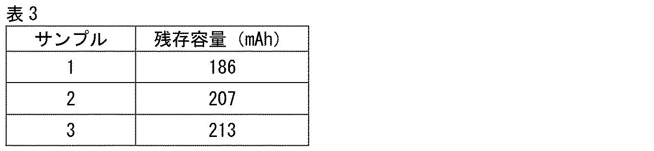
- the results of the second test are shown in Table 3.
- the remaining capacity of Sample 3 was greater than the remaining capacity of Sample 1 and the remaining capacity of Sample 2. From this, it was confirmed that the use of the metal porous body 10 as the negative electrode of a nickel-zinc battery exhibits excellent self-discharge characteristics.
- porous metal body 10B porous metal body 10B according to a second embodiment will be described.
- the points different from the metal porous body 10 will be mainly explained, and redundant explanations will not be repeated.
- the metal porous body 10B has a metal skeleton 11.
- the metal skeleton 11 has a metal layer 12 and a hollow part 13. Regarding these points, the configuration of the metal porous body 10B is common to the configuration of the metal porous body 10.
- the Vickers hardness of the metal material constituting the metal layer 12 is 600 Hv or less. That is, in the metal porous body 10B, the tin content of the metal layer 12 may be 99.99 mass percent or more (or 99.9 mass percent or more), but it does not have to be.
- Specific examples of metal materials having a Vickers hardness of 600 Hv or less include aluminum, copper, nickel, etc. in addition to tin.
- the Vickers hardness of the metal material constituting the metal layer 12 is measured according to the Vickers hardness test method defined in JIS Z 2244.
- FIG. 12 is a schematic cross-sectional view showing the internal structure of the porous metal body 10B.
- the metal porous body 10B further includes a core material 17.
- the core material 17 is made of a resin material such as urethane.
- the core material 17 is filled in the hollow portion 13.
- the content of the core material 17 in the metal porous body 10B is preferably 5 g/m 2 or more and 100 g/m 2 or less.
- the content of the core material 17 in the porous metal body 10B is obtained by dividing the mass of the core material 17 measured by total organic carbon (TOC) measurement by the apparent area of the porous metal body 10. .
- TOC total organic carbon
- FIG. 13 is a process diagram showing a method for manufacturing the porous metal body 10B.
- the method for manufacturing the porous metal body 10B includes a preparation step S1, a conductive treatment step S2, and a plating step S3.
- the method for manufacturing the metal porous body 10B may include a fired layer forming step S5 in place of the conductive treatment step S2 and the plating step S3, and a fired layer forming step in place of the conductive treatment step S2. It may have S5. Regarding these points, the method for manufacturing the porous metal body 10B is common to the method for manufacturing the porous metal body 10.
- the method for manufacturing the metal porous body 10B does not include the resin molded body removal step S4. Therefore, the resin molded body 20 remains in the metal porous body 10B as the core material 17. In this regard, the method for manufacturing the porous metal body 10B is different from the method for manufacturing the porous metal body 10.
- the metal porous body 10 When a load is applied to the porous metal body 10 from the outside, the load is supported only by the metal skeleton 11. Therefore, the metal porous body 10 is easily deformed by external loads and may have low rigidity.
- the metal porous body 10B when a load is applied from the outside, the load is supported not only by the metal skeleton 11 but also by the core material 17, so that it is difficult to deform under the load. Therefore, according to the metal porous body 10B, the rigidity is improved.
- the porous metal body 10 may have too low rigidity to become a self-supporting body.
- the core material 17 improves the rigidity, it is possible to make it a self-supporting body even when the metal skeleton 11 is formed of a soft metal such as tin.
Landscapes
- Chemical & Material Sciences (AREA)
- Chemical Kinetics & Catalysis (AREA)
- Electrochemistry (AREA)
- General Chemical & Material Sciences (AREA)
- Engineering & Computer Science (AREA)
- Manufacturing & Machinery (AREA)
- Materials Engineering (AREA)
- Battery Electrode And Active Subsutance (AREA)
Abstract
金属多孔体は、金属骨格を備えている。金属骨格の内部は、中空になっている。金属骨格は、錫の含有量が99.99質量パーセント以上である。
Description
本開示は、金属多孔体、ニッケル-亜鉛電池及び亜鉛空気電池に関する。本出願は、2022年3月24日に出願した日本特許出願である特願2022-048337号に基づく優先権を主張する。当該日本特許出願に記載された全ての記載内容は、参照によって本明細書に援用される。
例えば、再表2021-501446号公報(特許文献1)には、金属メッシュが記載されている。特許文献1に記載の金属メッシュは、例えば、ニッケル-亜鉛電池の負極に用いられている。
特許文献1に記載の金属メッシュは、銅により形成されている金属骨格と、金属骨格の表面にコーティングされている錫層とを有している。特許文献1に記載の金属メッシュがニッケル-亜鉛電池に用いられることにより、負極における亜鉛デンドライトの成長や水素発生が抑制される。
本開示の金属多孔体は、金属骨格を備える。金属骨格の内部は、中空になっている。金属骨格は、錫の含有量が99.99質量パーセント以上である。
[本開示が解決しようとする課題]
しかしながら、特許文献1に記載の金属メッシュにおいて、錫は、銅により形成されている金属骨格の表面にコーティングされているに過ぎず、当該金属骨格自体を構成しているわけではないため、コーディングの欠損等を原因として金属骨格が露出している箇所があれば、当該箇所が亜鉛デンドライトや水素の発生の起点となってしまう。
しかしながら、特許文献1に記載の金属メッシュにおいて、錫は、銅により形成されている金属骨格の表面にコーティングされているに過ぎず、当該金属骨格自体を構成しているわけではないため、コーディングの欠損等を原因として金属骨格が露出している箇所があれば、当該箇所が亜鉛デンドライトや水素の発生の起点となってしまう。
本開示は、上記のような従来技術の問題点に鑑みてなされたものである。より具体的には、本開示は、ニッケル-亜鉛電池又は亜鉛空気電池の負極に用いられた際に亜鉛デンドライトや水素の発生を抑制可能な金属多孔体を提供するものである。
[本開示の効果]
本開示の金属多孔体によると、ニッケル-亜鉛電池又は亜鉛空気電池の負極に用いられた際に亜鉛デンドライトや水素の発生を抑制可能である。
本開示の金属多孔体によると、ニッケル-亜鉛電池又は亜鉛空気電池の負極に用いられた際に亜鉛デンドライトや水素の発生を抑制可能である。
[本開示の実施形態の説明]
まず、本開示の実施態様を列記して説明する。
まず、本開示の実施態様を列記して説明する。
(1)実施形態に係る金属多孔体は、金属骨格を備えている。金属骨格の内部は、中空になっている。金属骨格は、錫の含有量が99.99質量パーセント以上である。
上記(1)の金属多孔体によると、ニッケル-亜鉛電池又は亜鉛空気電池の負極に用いられた際に亜鉛デンドライトや水素の発生を抑制可能である。
(2)上記(1)の金属多孔体では、金属骨格が、電解錫めっき層からなっていてもよい。
(3)上記(2)の金属多孔体では、金属骨格中の炭素量が100mg/m2以下であってもよい。
(4)上記(1)の金属多孔体では、金属骨格が、金属骨格の内部側を向いている第1面及び第1面の反対面である第2面を含む第1層と、第2面上に配置されている第2層とを有していてもよい。第1層は、焼成された錫粒子の層であってもよい。第2層は、電解錫めっき層であってもよい。
(5)上記(1)の金属多孔体では、金属骨格が、焼成された錫粒子の層からなっていてもよい。
(6)上記(1)から(5)の金属多孔体では、金属骨格が、三次元網目構造を有していてもよい。
(7)上記(6)の金属多孔体では、金属多孔体の内部に、金属骨格により画されている複数の連続気孔が存在していてもよい。金属多孔体の気孔率は、50パーセント以上であってもよい。
(8)上記(1)から(7)の金属多孔体では、金属骨格の厚さが、0.3μm以上100μm以下であってもよい。
上記(8)の金属多孔体によると、金属骨格が軟質であっても、金属多孔体の剛性を確保することができる。
(9)実施形態に係るニッケル-亜鉛電池は、正極と、負極とを備えている。負極は、上記(1)から(8)の金属多孔体により形成されている。
上記(9)のニッケル-亜鉛電池によると、負極における亜鉛デンドライト及び水素の発生を抑制可能である。
(10)実施形態に係る亜鉛空気電池は、正極と、負極とを備えている。負極は、上記(1)から(8)の金属多孔体により形成されている。
上記(10)の亜鉛空気電池によると、負極における亜鉛デンドライト及び水素の発生を抑制可能である。
(11)他の実施形態に係る金属多孔体は、金属骨格と芯材とを備えている。金属骨格は、ビッカース硬さが600Hv以下の金属材料により形成されている。芯材は、金属骨格の内部に充填されている。
上記(11)の金属多孔体によると、金属骨格が軟質な金属材料により形成されていても、金属多孔体の剛性を確保可能である。
(12)上記(11)の金属多孔体では、金属材料の錫の含有量が、99.99質量パーセント以上であってもよい。
(13)上記(11)又は(12)の金属多孔体では、芯材が、樹脂材料により形成されていてもよい。
(14)上記(13)の金属多孔体では、金属多孔体中の芯材の含有量が、5g/m2以上100g/m2以下であってもよい。
(15)上記(10)から(14)の金属多孔体では、金属骨格が、三次元網目構造を有していてもよい。
(16)上記(15)の金属多孔体では、金属多孔体の内部に、金属骨格により画されている複数の連続気孔が存在していてもよい。金属多孔体の気孔率は、50パーセント以上であってもよい。
[本開示の実施形態の詳細]
次に、本開示の実施形態の詳細を、図面を参照しながら説明する。以下の図面では、同一又は相当する部分に同一の参照符号を付し、重複する説明は繰り返さないものとする。
次に、本開示の実施形態の詳細を、図面を参照しながら説明する。以下の図面では、同一又は相当する部分に同一の参照符号を付し、重複する説明は繰り返さないものとする。
(第1実施形態)
第1実施形態に係る金属多孔体(金属多孔体10)を説明する。
第1実施形態に係る金属多孔体(金属多孔体10)を説明する。
<金属多孔体10の構成>
図1は、金属多孔体10の斜視図である。図1に示されるように、金属多孔体10は、例えばシート状になっている。金属多孔体10の厚さを、厚さT1とする。厚さT1は、例えば0.1mm以上3.0mm以下である。但し、厚さT1は、これに限られるものではない。
図1は、金属多孔体10の斜視図である。図1に示されるように、金属多孔体10は、例えばシート状になっている。金属多孔体10の厚さを、厚さT1とする。厚さT1は、例えば0.1mm以上3.0mm以下である。但し、厚さT1は、これに限られるものではない。
図2は、金属多孔体10の内部構造を示す模式的な断面図である。図3は、図2中のIII-IIIにおける模式的な断面図である。図2及び図3に示されるように、金属多孔体10は、金属骨格11を有している。
金属骨格11は、例えば、三次元網目構造を有している。すなわち、金属骨格11は、一体的に連続して形成されている。金属骨格11は、金属層12と、中空部13とを有している。金属層12は、金属骨格11の表面にある。中空部13は、金属骨格11の内部にある。すなわち、金属骨格11は、内部が中空になっている。金属骨格11は、その延在方向に直交する断面視において、例えば略三角形状になっている。
金属層12は、錫(Sn)の含有量が99.99質量パーセント以上の金属材料により形成されている。金属層12は、錫の含有量が99.9質量パーセント以上の金属材料により形成されていてもよい。
金属層12中の錫以外の残部は、例えば、炭素(C)、窒素(N)、銅(Cu)、ナトリウム(Na)、鉄(Fe)、鉛(Pb)、ビスマス(Bi)、アンチモン(Sb)、ヒ素(As)、亜鉛(Zn)等である。金属骨格11(金属層12)中の炭素量は、例えば100mg/m2以下である。金属骨格11中の単組量は、金属骨格11中に含まれている炭素の質量を金属多孔体10の見かけ面積で除した値である。金属多孔体10の見かけ面積は、金属多孔体10を内部構造を考慮せずに板材とみなした際の表面積である。より具体的には、金属多孔体10を板材とみなし、当該板材の2つの主面の面積と当該板材の4つの側面の面積との合計が、金属多孔体10の見かけ面積となる。
金属層12中の錫の含有量は、以下の方法により測定される。第1に、金属多孔体10が溶液中に溶解される。この溶液は、例えば、1パーセント硝酸を添加した1mоl/L塩酸である。第2に、上記の溶液に対して高周波誘導結合質量(ICP:Inductively Coupled Plasma)分析が行われることにより、当該溶液中の錫の質量が測定される。この溶液中の錫の質量をこの溶液に溶解させた金属多孔体10の質量で除することにより、金属層12中の錫の含有量が得られる。金属骨格11中の炭素量は、金属中炭素分析装置を用いた非分散型赤外線分析法により得られた金属骨格11中の炭素の質量を金属多孔体10の見かけ面積で除することにより得られる。
金属層12は、第1層12aと第2層12bとを有していてもよい。第1層12aは、中空部13側にある層である。第2層12bは、金属骨格11の表面側(すなわち、後述する気孔15側)にある層である。第1層12aは、例えばスパッタリングにより形成されているスパッタリング層である。
第1層12aは、第1面と、第2面とを有している。第1面は、中空部13側を向いている面である。第2面は、第1面の反対面である。第2層12bは、第1層12aの第2面上に配置されている。第2層12bは、例えば電解めっきにより形成されている電解錫めっき層である。金属層12は、電解錫めっき層からなっていてもよい。
金属層12は、焼成された錫粒子の層からなっていてもよい。金属層12中において、複数の錫粒子は、互いにネッキングされている。第1層12aは焼成された錫粒子の層であってもよく、第2層12bは電解めっきにより形成されている電解錫めっき層であってもよい。
金属骨格11の厚さ(金属層12の厚さ)を、厚さT2とする。厚さT2は、金属骨格11の剛性を確保する観点から、好ましくは、0.3μm以上100μm以下である。厚さT2においては、第1に、走査型電子顕微鏡(SEM:Scanning Electron Microscope)を用いて、金属骨格11の延在方向に直交する金属骨格11の断面画像が取得される。第2に、この断面画像に基づいて、金属層12の厚さが測定される。この際、金属層12の厚さは、最小値となる箇所において測定される。この測定値が、厚さT2となる。
金属多孔体10は、複数のセル14により構成されている。図4は、セル14の模式的な斜視図である。図4には、1つのセル14のみが示されている。図4に示されているように、セル14は多面体構造になっており、当該多面体構造の各辺に対応する部分が金属骨格11になっている。セル14の多面体構造体は、例えば十二面体構造である。但し、セル14の多面体構造は、これに限らない。セル14の多面体構造は、立方体構造、二十面体構造等であってもよい。
セル14の内部には、金属骨格11により画されている気孔15が存在している。上記のとおり、金属多孔体10は、複数のセル14により構成されているため、金属多孔体10の内部には、複数の気孔15が存在していることになる。
セル14は、複数の孔16を有している。孔16の周囲は、金属骨格11により取り囲まれている。孔16は、気孔15に連通している。そのため、隣り合う2つのセル14の各々の気孔15は、連続気孔になっている。
金属多孔体10の気孔率は、例えば50パーセント以上である。金属多孔体10の気孔率は、70パーセント以上であることが好ましく、90パーセント以上であることがさらに好ましい。金属多孔体10の気孔率は、金属多孔体10の質量をA、金属多孔体10の見かけの体積をB、金属多孔体10の真密度をCとすると、{1-A/(B×C)}×100により算出される。なお、金属多孔体10の見かけの体積は、金属多孔体10がシート状である場合、幅×長さ×厚さT1により算出されることになる。
気孔15の平均径は、例えば、200μm以上1000μm以下である。気孔15の平均径の測定においては、第1に、SEMを用いて金属多孔体10の断面画像を取得する。第2に、上記の断面画像において、1インチ(=25.4mm)あたりのセル14の数をカウントする。そして、25.4mmをカウントされたセル14の数で除した値が、気孔15の平均径となる。
<金属多孔体10の製造方法>
以下に、金属多孔体10の製造方法を説明する。
以下に、金属多孔体10の製造方法を説明する。
図5は、金属多孔体10の製造方法を示す工程図である。図5に示されるように、金属多孔体10の製造方法は、準備工程S1と、導電処理工程S2と、めっき工程S3と、樹脂成形体除去工程S4とを有している。導電処理工程S2は、準備工程S1の後に行われる。めっき工程S3は、導電処理工程S2の後に行われる。樹脂成形体除去工程S4は、めっき工程S3の後に行われる。
準備工程S1では、樹脂成形体20が準備される。樹脂成形体20は発泡樹脂である。樹脂成形体20は、例えばウレタン等の樹脂材料により形成されている。図6は、樹脂成形体20の模式的な断面図である。図6に示されるように、樹脂成形体20は、骨格21を有している。骨格21は、三次元網目構造を有している。骨格21は、中実になっている。
樹脂成形体20の内部には、複数の気孔22が存在している。気孔22は、骨格21により画されている。樹脂成形体20に対しては、除膜処理(例えば、爆発処理を行うことにより隣り合う2つの気孔22の間の隔壁を除去すること)が行われている。そのため、複数の気孔22は、連続気孔になっている。なお、樹脂成形体20の気孔率及び気孔22の平均径は、金属多孔体10の気孔率及び気孔15の平均径に合わせて適宜選択される。
導電処理工程S2では骨格21の表面に対する導電処理が行われる。この導電処理は、例えば、骨格21の表面上に錫をスパッタリングすることにより行われる。この導電処理が行われることにより、骨格21の表面に導電層が形成される。なお、上記の導電処理が行われることにより、隣り合う2つの気孔22の間にある隔壁の表面上にも、導電層が形成される。
めっき工程S3では、導電処理工程S2において形成された導電層に通電して電解めっきを行うことにより、当該導電層上に電解めっき層が形成される。
樹脂成形体除去工程S4では、樹脂成形体20の除去が行われる。樹脂成形体20は、例えば、上記の導電層及びめっき層の構成材料(錫)の融点未満の温度(上記の導電層及びめっき層が錫により形成されている場合、例えば175℃)でイオン液体(例えば、ジエタノールアミン)を用いて溶解除去される。樹脂成形体20の除去後に、上記の導電層及びめっき層が、金属層12になる。
導電処理工程S2は、骨格21の表面に炭素を塗布することにより行われてもよい。この場合、めっき工程S3において形成されるめっき層のみが、金属層12を構成することになる。
金属多孔体10の製造方法は、導電処理工程S2及びめっき工程S3を有していなくてもよい。図7は、変形例1に係る金属多孔体10の製造方法を示す工程図である。図7に示されるように、導電処理工程S2及びめっき工程S3の代わりに、焼成層形成工程S5が行われてもよい。
焼成層形成工程S5では、第1に、錫粒子及びバインダを含むペーストが、骨格21の表面上及び隣り合う2つの気孔22の間にある隔壁の表面上に塗布される。バインダは、例えば、カルボキシメチルセルロース(CMC)である。第2に、塗布されたペーストが焼成される。この焼成は、錫の融点未満の温度で行われる。これにより、塗布されたペースト中において隣り合う錫粒子同士がネッキングして金属結合され、塗布されたペーストが焼成された錫粒子の層となる。この焼成された錫粒子の層が、樹脂成形体除去工程S4の後に金属層12となる。
図8は、変形例2に係る金属多孔体10の製造方法を示す工程図である。図8に示されるように、金属多孔体10の製造方法は、導電処理工程S2に代えて、焼成層形成工程S5を有していてもよい。この場合、焼成された錫粒子の層が導電層となり、めっき工程S3において、焼成された錫粒子の層に通電することにより電解めっきが行われる。この場合、樹脂成形体除去工程S4の後に、焼成された錫粒子の層及びめっき工程S3において形成されるめっき層が、金属層12となる。
金属多孔体10は、例えば、ニッケル-亜鉛電池100又は亜鉛空気電池110に用いられる。図9は、ニッケル-亜鉛電池100の模式的な断面図である。図9に示されるように、ニッケル-亜鉛電池100は、負極101(亜鉛負極)と、正極102(水酸化ニッケル正極)と、セパレータ103とを有している。
負極101には、負極活物質が内部に充填されている金属多孔体10が用いられる。負極活物質は、酸化亜鉛を含んでいる。正極102には、正極活物質が内部に充填されている金属多孔体が用いられる。正極活物質は、水酸化ニッケルを含んでいる。セパレータ103は、負極101と正極102とにより挟み込まれている。セパレータ103は、水酸化物イオンを透過可能な材料により形成されている。なお、図示されていないが、負極101、正極102及びセパレータ103は、電解液中に浸漬されている。電解液は、例えば酸化亜鉛が溶解されている水酸化カリウム水溶液である。
充電が行われている際に、正極102では、水酸化ニッケル及び電解液中の水酸化物イオンが反応することにより、電子が放出されるとともにオキシ水酸化ニッケルが生じる。また、充電が行われている際、負極101では、正極102から放出された電子、酸化亜鉛、電解液中の水酸化物イオン及び電解液中の水が反応して亜鉛が生じる。他方で、放電が行われている際、上記とは逆の反応が生じ、正極102から負極101へと電流が流れる。
図10は、亜鉛空気電池110の模式的な断面図である。図10に示されるように、亜鉛空気電池110は、負極111(亜鉛負極)と、正極112(空気極)と、セパレータ113とを有している。
負極111には、負極活物質が内部に充填されている金属多孔体10が用いられる。負極活物質は、酸化亜鉛を含んでいる。正極112には、金属多孔体が用いられる。セパレータ113は、負極111と正極112とにより挟み込まれている。セパレータ113は水酸化物イオンを透過可能な材料により形成されている。なお、図示されていないが、負極111は、電解液中に浸漬されている。
充電が行われている際、正極112では、水酸化物イオンが反応することにより、電子が放出されるとともに酸素及び水が生じる。また、充電が行われている際、負極111では、正極112から放出された電子、酸化亜鉛、電解液中の水酸化物イオン及び電解液中の水が反応して亜鉛が生じる。他方で、放電が行われている際には、上記とは逆の反応が生じ、正極112から負極111へと電流が流れる。
<金属多孔体10の効果>
以下に、金属多孔体10の効果を、比較例に係る金属多孔体と対比しながら説明する。比較例に係る金属多孔体を、金属多孔体10Aとする。金属多孔体10Aは、金属骨格11が銅により形成されており、金属骨格11の表面に錫の層がコーティングされている点に関して、金属多孔体10と異なっている。
以下に、金属多孔体10の効果を、比較例に係る金属多孔体と対比しながら説明する。比較例に係る金属多孔体を、金属多孔体10Aとする。金属多孔体10Aは、金属骨格11が銅により形成されており、金属骨格11の表面に錫の層がコーティングされている点に関して、金属多孔体10と異なっている。
ニッケル-亜鉛電池100又は亜鉛空気電池110の負極では、亜鉛デンドライト又は水素の発生が生じることがある。金属多孔体10Aをニッケル-亜鉛電池100又は亜鉛空気電池110の負極に用いた場合、このようなデンドライト又は水素の発生が抑制されることがある。
しかしながら、金属多孔体10Aでは、錫の層が、銅により形成されている金属骨格11の表面にコーティングされているに過ぎない。そのため、錫の層の欠損等により金属骨格11の表面が露出していると、その部分がデンドライト又は水素の発生の起点となってしまう。このように、金属多孔体10Aをニッケル-亜鉛電池100又は亜鉛空気電池110の負極に用いる場合、ニッケル-亜鉛電池100又は亜鉛空気電池110の負極の表面における亜鉛デンドライト又は水素の発生の抑制が不十分となることがある。
他方で、金属多孔体10では、金属骨格11がほぼ錫により形成されていることになるため、錫以外の材料が負極の表面に露出することはなく、亜鉛デンドライト又は水素の発生が抑制されることになる。
<実施例>
ニッケル-亜鉛電池のサンプルとして、サンプル1からサンプル3が準備された。サンプル1からサンプル3の正極には、ニッケルにより形成されている金属多孔体(ニッケル多孔体)が用いられた。ニッケル多孔体の内部には、正極活物質スラリーが充填された。正極活物質スラリーの乾燥後の組成は、水酸化ニッケル90質量パーセント、水酸化コバルト7質量パーセント、CMC(造粒バインダ)0.3質量パーセント、SBR(スチレンブタジエンゴム)2.7質量パーセントとされた。正極活物質中の固定分比率は、78質量パーセントとされた。
ニッケル-亜鉛電池のサンプルとして、サンプル1からサンプル3が準備された。サンプル1からサンプル3の正極には、ニッケルにより形成されている金属多孔体(ニッケル多孔体)が用いられた。ニッケル多孔体の内部には、正極活物質スラリーが充填された。正極活物質スラリーの乾燥後の組成は、水酸化ニッケル90質量パーセント、水酸化コバルト7質量パーセント、CMC(造粒バインダ)0.3質量パーセント、SBR(スチレンブタジエンゴム)2.7質量パーセントとされた。正極活物質中の固定分比率は、78質量パーセントとされた。
サンプル1からサンプル3の正極の作製においては、第1に、厚さが1.2mm、金属量が300g/m2のニッケル多孔体が準備された。第2に、ロールプレスにより厚みを調整した上で、ニッケル多孔体の内部に正極活物質スラリーが充填された。第3に、正極活物質スラリーが充填されたニッケル多孔体に対して、100℃での乾燥を行った上でロールプレスを行い、緻密化した。その結果、電極面積が30mm×30mm、厚さが0.45mm、計算上の容量が240mAhの正極が得られた。なお、正極には、ニッケルにより形成されているリードが溶接により取り付けられた。
サンプル1の負極には、銅により形成されている金属多孔体(銅多孔体)が用いられ、サンプル2の負極には銅により形成され、かつ表面に錫めっきが行われている金属多孔体(錫めっき銅多孔体)が用いられる。サンプル3の負極には、金属多孔体10が用いられた。サンプル1からサンプル3の金属多孔体では、金属量が200g/m2とされ、厚さが1.0mmとされた。サンプル1からサンプル3の金属多孔体では、気孔率がそれぞれ97.8パーセント、97.8パーセント及び97.2パーセントとされた。サンプル1からサンプル3に用いられた金属多孔体は、表1に示されている。
サンプル1からサンプル3では、金属多孔体の内部に、負極活物質スラリーが充填された。負極活物質スラリーの乾燥後の組成は、酸化亜鉛90質量パーセント、AB(アセチレンブラック)5質量パーセント、CMC0.5質量パーセント、PTFE(ポリテトラフルオロエチレン)1.5質量パーセント、SBR3質量パーセントとされた。負極活物質中の固定分比率は、60質量パーセントとされた。

サンプル1からサンプル3の負極の作製においては、第1に、表2に示されている多孔体が準備された。第2に、ロールプレスにより厚みを調整した上で、金属多孔体の内部に負極活物質スラリーが充填された。第3に、負極活物質スラリーが充填された金属多孔体に対して、100℃での乾燥を行った上でロールプレスを行い、緻密化した。その結果、電極面積が30mm×30mm、計算上の容量が400mAhの負極が得られた。なお、負極には、ニッケルにより形成されているリードが溶接により取り付けられた。
サンプル1からサンプル3では、上記の正極及び負極の間に厚さが150μmのアニオン導電膜をセパレータとして介在させることにより、電極群とした。この電極群は、ポリプロピレン製の袋内に配置され、当該袋を外側からアクリル板で挟んで固定した。電解液には、酸化亜鉛が飽和溶解された1mоl/Lの水酸化カリウム水溶液が用いられた。上記の袋内には、上記の電解液が上記の電極群が完全に浸漬されるまで供給されるとともに上記の電極群に減圧含浸された。
サンプル1からサンプル3に対しては、評価に先立ち、活性化が行われた。この活性化では、第1に、0.1Cで1.9Vまで充電を行い、その後に0.1Cで1.5Vまで放電を行うサイクルを3回繰り返した。第2に、0.2Cで1.9Vまで充電を行い、その後に0.2Cで1.5Vまで放電を行うサイクルを3回繰り返した。第3に、0.5Cで1.9Vまで充電を行い、その後に0.5Cで1.5Vまで放電を行うサイクルを3回繰り返した。
第1試験として、サンプル1からサンプル3の負極における放電容量の比較を行った。第1試験では、30℃の恒温槽中で、0.5Cで1.9Vまで充電を行った。CV時のカットオフは、5時間又は電流値で10mAとされた。第1試験では、0.2C、0.5C及び1Cで1.5Vになるまで放電が行われた。
第1試験の結果は、表2に示されている。表2に示されている放電容量は、N=5の平均値とされた。表2に示されるように、サンプル3が正常に動作することが確認された。

第2試験としてサンプル1からサンプル3の負極における自己放電特性が評価された。第2試験では、サンプル1からサンプル3が第1試験と同様の方法により充電された。充電完了後、サンプル1からサンプル3は、45℃の恒温槽中に15日間保存された。この保存後、サンプル1からサンプル3は、0.2Cで1.5Vになるまで放電され、残存容量が比較された。
第2試験の結果は、表3に示されている。表3に示されている残存容量は、N=5の平均値とされた。表3に示されるように、サンプル3の残存容量は、サンプル1の残存容量及びサンプル2の残存容量よりも多かった。このことから、ニッケル-亜鉛電池の負極として金属多孔体10を用いることにより優れた自己放電特性を示すことが確認された。
第3試験としてサンプル1からサンプル3における負極のサイクル特性が評価された。第3試験では、第1試験と同様の方法による充電及び0.5Cで1.5Vになるまでの放電が繰り返された。図11は、サンプル1からサンプル3における充放電のサイクル数と放電容量との関係を示すグラフである。図11中のグラフに示されている値は、N=5の平均値とされた。図11に示されているように、サンプル3では、サンプル1及びサンプル2と比較して、充放電のサイクル数の増加に伴う放電容量の低下が最も少なかった。このことから、ニッケル-亜鉛電池の負極として金属多孔体10を用いることにより優れたサイクル特性を示すことが確認された。
(第2実施形態)
第2実施形態に係る金属多孔体(金属多孔体10B)を説明する。ここでは、金属多孔体10と異なる点を主に説明し、重複する説明は繰り返さない。
第2実施形態に係る金属多孔体(金属多孔体10B)を説明する。ここでは、金属多孔体10と異なる点を主に説明し、重複する説明は繰り返さない。
<金属多孔体10Bの構成>
金属多孔体10Bは、金属骨格11を有している。金属骨格11は、金属層12と、中空部13を有している。これらの点に関して、金属多孔体10Bの構成は、金属多孔体10の構成と共通している。
金属多孔体10Bは、金属骨格11を有している。金属骨格11は、金属層12と、中空部13を有している。これらの点に関して、金属多孔体10Bの構成は、金属多孔体10の構成と共通している。
金属多孔体10Bでは、金属層12を構成している金属材料のビッカース硬さが、600Hv以下になっている。すなわち、金属多孔体10Bでは、金属層12の錫の含有量が99.99質量パーセント以上(又は99.9質量パーセント以上)になっていてもよいが、そうでなくてもよい。ビッカース硬さが600Hv以下となる金属材料の具体例としては、錫の他に、アルミニウム、銅、ニッケル等が挙げられる。金属層12を構成している金属材料のビッカース硬さは、JIS Z 2244に定められているビッカース硬さ試験法にしたがって測定される。
図12は、金属多孔体10Bの内部構造を示す模式的な断面図である。図12に示されるように、金属多孔体10Bは、芯材17をさらに有している。芯材17は、ウレタン等の樹脂材料により形成されている。芯材17は、中空部13に充填されている。金属多孔体10B中の芯材17の含有量は、5g/m2以上100g/m2以下であることが好ましい。金属多孔体10B中の芯材17の含有量は、全有機体炭素(TOC:Total Organic Carbon)測定により測定された芯材17の質量を金属多孔体10の見かけ面積で除することにより得られる。これらの点に関して、金属多孔体10Bの構成は、金属多孔体10の構成と異なっている。
<金属多孔体10Bの製造方法>
以下に、金属多孔体10Bの製造方法を説明する。
以下に、金属多孔体10Bの製造方法を説明する。
図13は、金属多孔体10Bの製造方法を示す工程図である。図13に示されているように、金属多孔体10Bの製造方法は、準備工程S1と、導電処理工程S2と、めっき工程S3とを有している。図示されていないが、金属多孔体10Bの製造方法は、導電処理工程S2及びめっき工程S3に代えて焼成層形成工程S5を有していてもよく、導電処理工程S2に代えて焼成層形成工程S5を有していてもよい。これらの点に関して、金属多孔体10Bの製造方法は、金属多孔体10の製造方法と共通している。
金属多孔体10Bの製造方法は、樹脂成形体除去工程S4を有していない。そのため、樹脂成形体20が、芯材17として金属多孔体10Bに残存する。この点に関して、金属多孔体10Bの製造方法は、金属多孔体10の製造方法と異なっている。
<金属多孔体10Bの効果>
以下に、金属多孔体10Bの効果を説明する。
以下に、金属多孔体10Bの効果を説明する。
金属多孔体10は、外部から荷重が加わった際に、当該荷重が金属骨格11のみにより支持される。そのため、金属多孔体10は、外部からの荷重に対して変形しやすく、剛性が低いことがある。他方で、金属多孔体10Bでは、外部から荷重が加わった際に、当該荷重が金属骨格11のみならず芯材17によっても支持されるため、当該荷重に対して変形しにくい。そのため、金属多孔体10Bによると、剛性が改善されることになる。
特に、金属骨格11が錫等の軟質金属により形成されている場合、金属多孔体10は、剛性が低すぎて自立体にならないことがある。金属多孔体10Bでは、芯材17により剛性が改善される結果、錫等の軟質金属により金属骨格11が形成されている場合であっても、自立体とすることが可能である。
今回開示された実施形態は全ての点で例示であって、制限的なものではないと考えられるべきである。本発明の範囲は上記の実施形態ではなく請求の範囲によって示され、請求の範囲と均等の意味及び範囲内での全ての変更が含まれることが意図される。
10 金属多孔体、10A,10B 金属多孔体、11 金属骨格、12 金属層、12a 第1層、12b 第2層、13 中空部、14 セル、15 気孔、16 孔、17 芯材、20 樹脂成形体、21 骨格、22 気孔、100 亜鉛電池、101 負極、102 正極、103 セパレータ、110 亜鉛空気電池、111 負極、112 正極、113 セパレータ、T1 厚さ、T2 厚さ、S1 準備工程、S2 導電処理工程、S3 めっき工程、S4 樹脂成形体除去工程、S5 焼成層形成工程。
Claims (16)
- 金属多孔体であって、
金属骨格を備え、
前記金属骨格の内部は、中空になっており、
前記金属骨格は、錫の含有量が99.99質量パーセント以上である、金属多孔体。 - 前記金属骨格は、電解錫めっき層からなる、請求項1に記載の金属多孔体。
- 前記金属骨格中の炭素量は、100mg/m2以下である、請求項2に記載の金属多孔体。
- 前記金属骨格は、前記金属骨格の内部側を向いている第1面及び前記第1面の反対面である第2面を含む第1層と、前記第2面上に配置されている第2層とを有し、
前記第1層は、焼成された錫粒子の層であり、
前記第2層は、電解錫めっき層である、請求項1に記載の金属多孔体。 - 前記金属骨格は、焼成された錫粒子の層からなる、請求項1に記載の金属多孔体。
- 前記金属骨格は、三次元網目構造を有する、請求項1から請求項5のいずれか1項に記載の金属多孔体。
- 前記金属多孔体の内部には、前記金属骨格により画されている複数の連続気孔が存在しており、
前記金属多孔体の気孔率は50パーセント以上である、請求項6に記載の金属多孔体。 - 前記金属骨格の厚さは、0.3μm以上100μm以下である、請求項1から請求項7のいずれか1項に記載の金属多孔体。
- 正極と、
負極とを備え、
前記負極は、請求項1から請求項8のいずれか1項に記載の前記金属多孔体により形成されている、ニッケル-亜鉛電池。 - 正極と、
負極とを備え、
前記負極は、請求項1から請求項8のいずれか1項に記載の前記金属多孔体により形成されている、亜鉛空気電池。 - 金属多孔体であって、
金属骨格と、
芯材とを備え、
前記金属骨格は、ビッカース硬さが600Hv以下の金属材料により形成されており、
前記芯材は、前記金属骨格の内部に充填されている、金属多孔体。 - 前記金属材料は、錫の含有量が99.99質量パーセント以上である、請求項11に記載の金属多孔体。
- 前記芯材は、樹脂材料により形成されている、請求項11又は請求項12に記載の金属多孔体。
- 前記金属多孔体中の前記芯材の含有量は、5g/m2以上100g/m2以下である、請求項13に記載の金属多孔体。
- 前記金属骨格は、三次元網目構造を有する、請求項11から請求項14のいずれか1項に記載の金属多孔体。
- 前記金属多孔体の内部には、前記金属骨格により画されている複数の連続気孔が存在しており、
前記金属多孔体の気孔率は、50パーセント以上である、請求項15に記載の金属多孔体。
Applications Claiming Priority (2)
| Application Number | Priority Date | Filing Date | Title |
|---|---|---|---|
| JP2022-048337 | 2022-03-24 | ||
| JP2022048337 | 2022-03-24 |
Publications (1)
| Publication Number | Publication Date |
|---|---|
| WO2023181552A1 true WO2023181552A1 (ja) | 2023-09-28 |
Family
ID=88100858
Family Applications (1)
| Application Number | Title | Priority Date | Filing Date |
|---|---|---|---|
| PCT/JP2022/047445 Ceased WO2023181552A1 (ja) | 2022-03-24 | 2022-12-22 | 金属多孔体、ニッケル-亜鉛電池及び亜鉛空気電池 |
Country Status (1)
| Country | Link |
|---|---|
| WO (1) | WO2023181552A1 (ja) |
Citations (8)
| Publication number | Priority date | Publication date | Assignee | Title |
|---|---|---|---|---|
| JPH07138792A (ja) * | 1993-09-14 | 1995-05-30 | Katayama Tokushu Kogyo Kk | 金属多孔体および該金属多孔体の製造方法 |
| JPH07326358A (ja) * | 1994-06-02 | 1995-12-12 | Matsushita Electric Ind Co Ltd | アルカリ電池 |
| CN101824619A (zh) * | 2010-06-01 | 2010-09-08 | 武汉银泰科技电源股份有限公司 | 一种泡沫锡材料的制备方法 |
| JP2011246779A (ja) * | 2010-05-28 | 2011-12-08 | Sumitomo Electric Ind Ltd | アルミニウム構造体の製造方法およびアルミニウム構造体 |
| WO2012049991A1 (ja) * | 2010-10-13 | 2012-04-19 | 住友電気工業株式会社 | 金属多孔体とその製造方法、および溶融塩電池 |
| JP2012132083A (ja) * | 2010-12-24 | 2012-07-12 | Sumitomo Electric Ind Ltd | 高耐食性を有する金属多孔体及びその製造方法 |
| CN109609795A (zh) * | 2018-11-30 | 2019-04-12 | 常德力元新材料有限责任公司 | 一种三维多孔锡材料的制备方法 |
| WO2019116631A1 (ja) * | 2017-12-15 | 2019-06-20 | 富山住友電工株式会社 | 金属多孔体の製造方法、及びめっき処理装置 |
-
2022
- 2022-12-22 WO PCT/JP2022/047445 patent/WO2023181552A1/ja not_active Ceased
Patent Citations (8)
| Publication number | Priority date | Publication date | Assignee | Title |
|---|---|---|---|---|
| JPH07138792A (ja) * | 1993-09-14 | 1995-05-30 | Katayama Tokushu Kogyo Kk | 金属多孔体および該金属多孔体の製造方法 |
| JPH07326358A (ja) * | 1994-06-02 | 1995-12-12 | Matsushita Electric Ind Co Ltd | アルカリ電池 |
| JP2011246779A (ja) * | 2010-05-28 | 2011-12-08 | Sumitomo Electric Ind Ltd | アルミニウム構造体の製造方法およびアルミニウム構造体 |
| CN101824619A (zh) * | 2010-06-01 | 2010-09-08 | 武汉银泰科技电源股份有限公司 | 一种泡沫锡材料的制备方法 |
| WO2012049991A1 (ja) * | 2010-10-13 | 2012-04-19 | 住友電気工業株式会社 | 金属多孔体とその製造方法、および溶融塩電池 |
| JP2012132083A (ja) * | 2010-12-24 | 2012-07-12 | Sumitomo Electric Ind Ltd | 高耐食性を有する金属多孔体及びその製造方法 |
| WO2019116631A1 (ja) * | 2017-12-15 | 2019-06-20 | 富山住友電工株式会社 | 金属多孔体の製造方法、及びめっき処理装置 |
| CN109609795A (zh) * | 2018-11-30 | 2019-04-12 | 常德力元新材料有限责任公司 | 一种三维多孔锡材料的制备方法 |
Similar Documents
| Publication | Publication Date | Title |
|---|---|---|
| US4251603A (en) | Battery electrode | |
| RU2554100C2 (ru) | Устройство аккумулирования электроэнергии и его электрод | |
| KR101326623B1 (ko) | 프라이머가 코팅된 양극 집전체 및 이를 포함하는 마그네슘 이차전지 | |
| CN114514643B (zh) | 包括具有改进的粘合强度的底涂层的集流体及其制造方法 | |
| JP7316772B2 (ja) | リチウム二次電池集電体に用いられる銅箔 | |
| US9368788B2 (en) | Layered iron electrode | |
| KR102855234B1 (ko) | 리튬 친화물질이 코팅된 리튬 이차전지용 음극 및 이의 제조방법 | |
| JP4967229B2 (ja) | アルカリ二次電池用負極板およびその負極板を適用したアルカリ二次電池。 | |
| JP2001313066A (ja) | アルカリ蓄電池 | |
| JP7105525B2 (ja) | 亜鉛電池 | |
| WO2023181613A1 (ja) | 金属多孔体 | |
| US9666381B2 (en) | Asymmetrical supercapacitor with alkaline electrolyte comprising a three-dimensional negative electrode and method for producing same | |
| JP2020087554A (ja) | 亜鉛電池用電解液及び亜鉛電池 | |
| JPH113699A (ja) | リチウムイオン二次電池用負極 | |
| US12494472B2 (en) | Method for manufacturing electrode for lithium secondary battery | |
| JP2000208144A (ja) | 電池用電極基板とその製造方法 | |
| WO2023181552A1 (ja) | 金属多孔体、ニッケル-亜鉛電池及び亜鉛空気電池 | |
| CN101030637B (zh) | 电池电极的制造方法和电池电极 | |
| KR20200060287A (ko) | 음극의 제조방법 및 이에 따른 음극을 포함하는 급속충전 성능이 개선된 이차전지 | |
| JP2020087516A (ja) | 亜鉛電池用負極の製造方法及び亜鉛電池の製造方法 | |
| JP2019216059A (ja) | 多孔膜、電池部材及び亜鉛電池 | |
| JP6881868B2 (ja) | 可逆的二酸化マンガン電極、その製造方法、その使用、およびそのような電極を含む充電式アルカリマンガン電池 | |
| KR20210071610A (ko) | 리튬 금속 복합전극 및 이의 제조방법 | |
| US20040219427A1 (en) | Non-sintered electrode for an electrochemical generator with an alkaline electrolyte | |
| KR20120054143A (ko) | 이차전지용 전극, 그 제조방법 및 이를 포함한 이차전지 |
Legal Events
| Date | Code | Title | Description |
|---|---|---|---|
| 121 | Ep: the epo has been informed by wipo that ep was designated in this application |
Ref document number: 22933679 Country of ref document: EP Kind code of ref document: A1 |
|
| NENP | Non-entry into the national phase |
Ref country code: DE |
|
| 122 | Ep: pct application non-entry in european phase |
Ref document number: 22933679 Country of ref document: EP Kind code of ref document: A1 |
|
| NENP | Non-entry into the national phase |
Ref country code: JP |