WO2023181323A1 - 画像処理システム、画像処理装置、画像処理方法及び画像処理プログラム - Google Patents
画像処理システム、画像処理装置、画像処理方法及び画像処理プログラム Download PDFInfo
- Publication number
- WO2023181323A1 WO2023181323A1 PCT/JP2022/014239 JP2022014239W WO2023181323A1 WO 2023181323 A1 WO2023181323 A1 WO 2023181323A1 JP 2022014239 W JP2022014239 W JP 2022014239W WO 2023181323 A1 WO2023181323 A1 WO 2023181323A1
- Authority
- WO
- WIPO (PCT)
- Prior art keywords
- quantization value
- data
- unit
- target area
- image processing
- Prior art date
- Legal status (The legal status is an assumption and is not a legal conclusion. Google has not performed a legal analysis and makes no representation as to the accuracy of the status listed.)
- Ceased
Links
Images









Classifications
-
- H—ELECTRICITY
- H04—ELECTRIC COMMUNICATION TECHNIQUE
- H04N—PICTORIAL COMMUNICATION, e.g. TELEVISION
- H04N19/00—Methods or arrangements for coding, decoding, compressing or decompressing digital video signals
- H04N19/10—Methods or arrangements for coding, decoding, compressing or decompressing digital video signals using adaptive coding
- H04N19/134—Methods or arrangements for coding, decoding, compressing or decompressing digital video signals using adaptive coding characterised by the element, parameter or criterion affecting or controlling the adaptive coding
- H04N19/167—Position within a video image, e.g. region of interest [ROI]
-
- H—ELECTRICITY
- H04—ELECTRIC COMMUNICATION TECHNIQUE
- H04N—PICTORIAL COMMUNICATION, e.g. TELEVISION
- H04N19/00—Methods or arrangements for coding, decoding, compressing or decompressing digital video signals
- H04N19/10—Methods or arrangements for coding, decoding, compressing or decompressing digital video signals using adaptive coding
- H04N19/102—Methods or arrangements for coding, decoding, compressing or decompressing digital video signals using adaptive coding characterised by the element, parameter or selection affected or controlled by the adaptive coding
- H04N19/124—Quantisation
-
- H—ELECTRICITY
- H04—ELECTRIC COMMUNICATION TECHNIQUE
- H04N—PICTORIAL COMMUNICATION, e.g. TELEVISION
- H04N19/00—Methods or arrangements for coding, decoding, compressing or decompressing digital video signals
- H04N19/10—Methods or arrangements for coding, decoding, compressing or decompressing digital video signals using adaptive coding
- H04N19/102—Methods or arrangements for coding, decoding, compressing or decompressing digital video signals using adaptive coding characterised by the element, parameter or selection affected or controlled by the adaptive coding
- H04N19/124—Quantisation
- H04N19/126—Details of normalisation or weighting functions, e.g. normalisation matrices or variable uniform quantisers
-
- H—ELECTRICITY
- H04—ELECTRIC COMMUNICATION TECHNIQUE
- H04N—PICTORIAL COMMUNICATION, e.g. TELEVISION
- H04N19/00—Methods or arrangements for coding, decoding, compressing or decompressing digital video signals
- H04N19/10—Methods or arrangements for coding, decoding, compressing or decompressing digital video signals using adaptive coding
- H04N19/134—Methods or arrangements for coding, decoding, compressing or decompressing digital video signals using adaptive coding characterised by the element, parameter or criterion affecting or controlling the adaptive coding
- H04N19/146—Data rate or code amount at the encoder output
-
- H—ELECTRICITY
- H04—ELECTRIC COMMUNICATION TECHNIQUE
- H04N—PICTORIAL COMMUNICATION, e.g. TELEVISION
- H04N19/00—Methods or arrangements for coding, decoding, compressing or decompressing digital video signals
- H04N19/10—Methods or arrangements for coding, decoding, compressing or decompressing digital video signals using adaptive coding
- H04N19/134—Methods or arrangements for coding, decoding, compressing or decompressing digital video signals using adaptive coding characterised by the element, parameter or criterion affecting or controlling the adaptive coding
- H04N19/154—Measured or subjectively estimated visual quality after decoding, e.g. measurement of distortion
-
- H—ELECTRICITY
- H04—ELECTRIC COMMUNICATION TECHNIQUE
- H04N—PICTORIAL COMMUNICATION, e.g. TELEVISION
- H04N19/00—Methods or arrangements for coding, decoding, compressing or decompressing digital video signals
- H04N19/10—Methods or arrangements for coding, decoding, compressing or decompressing digital video signals using adaptive coding
- H04N19/169—Methods or arrangements for coding, decoding, compressing or decompressing digital video signals using adaptive coding characterised by the coding unit, i.e. the structural portion or semantic portion of the video signal being the object or the subject of the adaptive coding
- H04N19/17—Methods or arrangements for coding, decoding, compressing or decompressing digital video signals using adaptive coding characterised by the coding unit, i.e. the structural portion or semantic portion of the video signal being the object or the subject of the adaptive coding the unit being an image region, e.g. an object
-
- H—ELECTRICITY
- H04—ELECTRIC COMMUNICATION TECHNIQUE
- H04N—PICTORIAL COMMUNICATION, e.g. TELEVISION
- H04N19/00—Methods or arrangements for coding, decoding, compressing or decompressing digital video signals
- H04N19/10—Methods or arrangements for coding, decoding, compressing or decompressing digital video signals using adaptive coding
- H04N19/169—Methods or arrangements for coding, decoding, compressing or decompressing digital video signals using adaptive coding characterised by the coding unit, i.e. the structural portion or semantic portion of the video signal being the object or the subject of the adaptive coding
- H04N19/17—Methods or arrangements for coding, decoding, compressing or decompressing digital video signals using adaptive coding characterised by the coding unit, i.e. the structural portion or semantic portion of the video signal being the object or the subject of the adaptive coding the unit being an image region, e.g. an object
- H04N19/172—Methods or arrangements for coding, decoding, compressing or decompressing digital video signals using adaptive coding characterised by the coding unit, i.e. the structural portion or semantic portion of the video signal being the object or the subject of the adaptive coding the unit being an image region, e.g. an object the region being a picture, frame or field
-
- H—ELECTRICITY
- H04—ELECTRIC COMMUNICATION TECHNIQUE
- H04N—PICTORIAL COMMUNICATION, e.g. TELEVISION
- H04N19/00—Methods or arrangements for coding, decoding, compressing or decompressing digital video signals
- H04N19/10—Methods or arrangements for coding, decoding, compressing or decompressing digital video signals using adaptive coding
- H04N19/169—Methods or arrangements for coding, decoding, compressing or decompressing digital video signals using adaptive coding characterised by the coding unit, i.e. the structural portion or semantic portion of the video signal being the object or the subject of the adaptive coding
- H04N19/17—Methods or arrangements for coding, decoding, compressing or decompressing digital video signals using adaptive coding characterised by the coding unit, i.e. the structural portion or semantic portion of the video signal being the object or the subject of the adaptive coding the unit being an image region, e.g. an object
- H04N19/176—Methods or arrangements for coding, decoding, compressing or decompressing digital video signals using adaptive coding characterised by the coding unit, i.e. the structural portion or semantic portion of the video signal being the object or the subject of the adaptive coding the unit being an image region, e.g. an object the region being a block, e.g. a macroblock
-
- H—ELECTRICITY
- H04—ELECTRIC COMMUNICATION TECHNIQUE
- H04N—PICTORIAL COMMUNICATION, e.g. TELEVISION
- H04N19/00—Methods or arrangements for coding, decoding, compressing or decompressing digital video signals
- H04N19/30—Methods or arrangements for coding, decoding, compressing or decompressing digital video signals using hierarchical techniques, e.g. scalability
-
- H—ELECTRICITY
- H04—ELECTRIC COMMUNICATION TECHNIQUE
- H04N—PICTORIAL COMMUNICATION, e.g. TELEVISION
- H04N19/00—Methods or arrangements for coding, decoding, compressing or decompressing digital video signals
- H04N19/40—Methods or arrangements for coding, decoding, compressing or decompressing digital video signals using video transcoding, i.e. partial or full decoding of a coded input stream followed by re-encoding of the decoded output stream
-
- H—ELECTRICITY
- H04—ELECTRIC COMMUNICATION TECHNIQUE
- H04N—PICTORIAL COMMUNICATION, e.g. TELEVISION
- H04N19/00—Methods or arrangements for coding, decoding, compressing or decompressing digital video signals
- H04N19/50—Methods or arrangements for coding, decoding, compressing or decompressing digital video signals using predictive coding
- H04N19/593—Methods or arrangements for coding, decoding, compressing or decompressing digital video signals using predictive coding involving spatial prediction techniques
Definitions
- the present invention relates to an image processing system, an image processing device, an image processing method, and an image processing program.
- the quantization value (parameter that determines the compression rate) of each area is reduced to the limit that AI can recognize the recognition target. Yes, it includes the quantization parameter, quantization step size, etc.For example, the QP value of the video encoding standard H.265/HEVC) is increased (in other words, with the limit quantization value). There are ways to do this.
- the above image capture can be achieved. Even in a device, the data size of encoded data can be reduced.
- One aspect of the present invention is to provide an image processing system, an image processing device, an image processing method, and an image processing program suitable for transmitting images used for recognition processing by AI.
- an image processing system includes: Based on the results of the recognition process, a target area necessary to recognize the recognition target in the image data, a non-target area other than the target area, a quantization value of the target area necessary to recognize the recognition target, and a a determining unit that determines a quantization value of the non-target region; a first encoding unit that encodes the entire area of the image data using a quantized value of the target area and generates first encoded data; a second encoding unit that encodes the entire area of the image data using the quantized value of the non-target area and generates second encoded data; Generate reconstructed image data using the target area in the first decoded data obtained by decoding the first encoded data and the non-target area in the second decoded data obtained by decoding the second coded data. a reconstruction unit that performs and a re-encoding unit that re-encodes the reconstructed image data and generates re-encoded data.
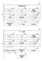
- FIG. 1A is a first diagram showing an example of the system configuration of an image processing system.
- FIG. 1B is a second diagram showing an example of the system configuration of the image processing system.
- FIG. 1C is a third diagram showing an example of the system configuration of the image processing system.
- FIG. 2 is a diagram showing an example of the hardware configuration of the image processing device and the server device.
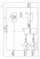
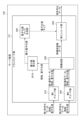
- FIG. 3 is a first diagram showing an example of the functional configuration of a layered encoding device.
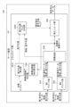
- FIG. 4 is a first diagram showing an example of the functional configuration of the transcoding section.
- FIG. 5 is a first diagram showing a specific example of processing by the layered encoding device and the transcoding unit.
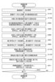
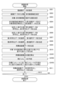
- FIG. 6 is a first flowchart showing the flow of image processing.
- FIG. 1A is a first diagram showing an example of the system configuration of an image processing system.
- FIG. 1B is a second diagram showing an example of the system configuration of the image processing system.
- FIG. 1C is a third
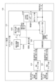
- FIG. 7 is a second diagram showing an example of the functional configuration of the transcoding section.
- FIG. 8 is a second diagram showing a specific example of processing by the layered encoding device and the transcoding unit.
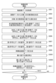
- FIG. 9 is a second flowchart showing the flow of image processing.
- FIG. 10A is a second diagram illustrating an example of the functional configuration of a layered encoding device.
- FIG. 10B is a third diagram showing an example of the functional configuration of the transcoding section.
- FIG. 11 is a third flowchart showing the flow of image processing.
- FIG. 12 is a fourth diagram showing an example of the functional configuration of the transcoding section.
- FIG. 13 is a fourth flowchart showing the flow of image processing.
- FIG. 14 is a fifth diagram showing an example of the functional configuration of the transcoding section.
- FIG. 14 is a fifth diagram showing an example of the functional configuration of the transcoding section.
- FIG. 15 is a first diagram showing a specific example of the processing of the correction coefficient calculating section.
- FIG. 16 is a fifth flowchart showing the flow of image processing.
- FIG. 17A is a third diagram illustrating an example of the functional configuration of a layered encoding device.
- FIG. 17B is a sixth diagram illustrating an example of the functional configuration of the transcoding section.
- FIG. 18 is a first diagram showing a specific example of processing by the quantization value calculation unit.
- FIG. 19 is a sixth flowchart showing the flow of image processing.
- FIG. 20 is a diagram illustrating a specific example of processing by the quantization value calculation unit and the quantization value map generation unit.
- FIG. 21 is a seventh flowchart showing the flow of image processing.
- FIG. 21 is a seventh flowchart showing the flow of image processing.
- FIG. 22 is a seventh diagram showing an example of the functional configuration of the transcoding section.
- FIG. 23 is a second diagram showing a specific example of the processing of the quantization value calculation unit.
- FIG. 24 is an eighth flowchart showing the flow of image processing.
- FIG. 25 is an eighth diagram showing an example of the functional configuration of the transcoding section.
- FIG. 26 is a ninth flowchart showing the flow of image processing.
- FIG. 27 is a ninth diagram showing an example of the functional configuration of the transcoding section.
- FIG. 28 is a second diagram showing a specific example of the processing of the correction coefficient calculation unit.
- FIG. 29 is a tenth flowchart showing the flow of image processing.
- FIG. 30 is a tenth diagram showing an example of the functional configuration of the transcoding section.
- FIG. 31 is a third diagram showing a specific example of the processing of the correction coefficient calculation unit.
- FIG. 32 is an eleventh flowchart showing the flow of image processing.
- FIG. 30 is an eleventh diagram showing an example of the functional configuration of the transcoding section.
- FIG. 34 is a fourth diagram showing a specific example of the processing of the correction coefficient calculation unit.
- FIG. 35 is a twelfth flowchart showing the flow of image processing.
- FIG. 36 is a twelfth diagram showing an example of the functional configuration of the transcoding section.
- FIG. 37 is a fifth diagram showing a specific example of the processing of the correction coefficient calculating section.
- FIG. 38 is a thirteenth flowchart showing the flow of image processing.
- FIG. 1A is a first diagram showing an example of the system configuration of an image processing system.
- the image processing system 100 includes an imaging device 110, a hierarchical encoding device 111, and a server device 130.
- Hierarchical encoding device 111 and server device 130 are communicably connected via network 140 .
- the imaging device 110 photographs at a predetermined frame period and transmits moving image data to the hierarchical encoding device 111.
- Hierarchical encoding device 111 is placed near imaging device 110.
- the hierarchical encoding device 111 encodes the image data of each frame included in the moving image data, and generates first encoded data.
- ⁇ The area necessary for AI to recognize the recognition target included in the image data (target area), and ⁇ The limit quantization value necessary for AI to recognize the recognition target contained in the image data (limit quantization value) is determined, and the entire region of image data is encoded with the same limit quantization value.
- the hierarchical encoding device 111 encodes the image data of each frame included in the video data, and generates second encoded data.
- the hierarchical encoding device 111 when generating the second encoded data, ⁇ An area other than the area necessary for AI to recognize the recognition target included in the image data (non-target area), and - a predetermined quantization value suitable for encoding the non-target region; is determined, and the entire region of image data is encoded with the same predetermined quantization value.
- the layered encoding device 111 - Information regarding the first encoded data and the region and quantization value determined when generating the first encoded data; - Information regarding the second encoded data and the area and quantization value determined when generating the second encoded data; is transmitted to the server device 130.
- An image processing program is installed on the server device 130, and by executing the program, the server device 130 functions as the transcoding unit 121. Further, an image recognition program is installed in the server device 130, and by executing the program, the server device 130 functions as a re-encoded data acquisition unit 131, a video analysis unit 132, and a video display unit 133. do.
- the transcoding unit 121 decodes the first encoded data and second encoded data transmitted from the layered encoding device 111, and generates first decoded data and second decoded data. Further, the transcoding unit 121 extracts a target region from the first decoded data and a non-target region from the second decoded data based on the information regarding the region transmitted from the hierarchical encoding device 111. Furthermore, the transcoding unit 121 generates reconstructed image data by combining the extracted target area and non-target area.
- the transcoding unit 121 performs ⁇ Encode the target area in the reconstructed image data with a limit quantization value or a quantization value close to the limit quantization value, ⁇ Encoding non-target areas in the reconstructed image data with a predetermined quantization value, By doing so, re-encoded data is generated. Further, the transcoding unit 121 notifies the re-encoding data acquisition unit 131 of the re-encoding data.
- the re-encoded data acquisition unit 131 acquires re-encoded data, notifies the video analysis unit 132, and stores it in the re-encoded data storage unit 134.
- the video analysis unit 132 decodes the re-encoded data notified from the re-encoded data acquisition unit 131 and generates decoded data. Further, the video analysis unit 132 performs recognition processing using AI on the generated decoded data and recognizes a recognition target included in the decoded data. Further, the video analysis unit 132 outputs the recognition results to the user.
- the video display unit 133 reads out and decodes the re-encoded data in the range specified by the user from among the re-encoded data stored in the re-encoded data storage unit 134, and generates decoded data. Further, the video display unit 133 displays the generated decoded data to the user as video data.
- the image recognition program has a function to receive two types of encoded data and a function to receive two types of encoded data. There is no need to incorporate a reconfiguration function.
- the first encoded data and the second encoded data are transmitted, the reduction in the amount of data transmitted between the hierarchical encoding device 111 and the server device 130 can be maintained.
- the re-encoded data is stored in an amount comparable to that of the first encoded data and the second encoded data, the amount of stored data stored in the server device 130 can be reduced.
- the video analysis unit 132 can realize recognition processing by AI with high recognition accuracy. . -
- a non-target area that is an area other than the target area in the decoded data can be used as image data.
- an image processing system 100 As described above, according to the first embodiment, it is possible to provide an image processing system 100, an image processing method, and an image processing program suitable for transmitting images used for recognition processing by AI.
- FIG. 1B and FIG. 1C are second and third diagrams showing an example of the system configuration of the image processing system.
- the image processing system 100' or 100'' includes an imaging device 110, a hierarchical encoding device 111, an image processing device 120, and a server device 130.
- the image processing device 120 and the server device 130 (or the hierarchical encoding device 111 and the image processing device 120) are communicably connected via a network 140.
- the imaging device 110 and the hierarchical encoding device 111 are the same as the imaging device 110 and the hierarchical encoding device 111 described in FIG. 1A, so the description thereof will be omitted here.
- the layered encoding device 111 is - Information regarding the first encoded data and the region and quantization value determined when generating the first encoded data; - Information regarding the second encoded data and the area and quantization value determined when generating the second encoded data; is transmitted to the image processing device 120.
- An image processing program is installed in the image processing device 120, and by executing the program, the image processing device 120 functions as the transcoding unit 121.
- the transcoding unit 121 decodes the first encoded data and second encoded data transmitted from the layered encoding device 111, and generates first decoded data and second decoded data. Further, the transcoding unit 121 extracts a target region from the first decoded data and a non-target region from the second decoded data based on the information regarding the region transmitted from the hierarchical encoding device 111. Furthermore, the transcoding unit 121 generates reconstructed image data by combining the extracted target area and non-target area.
- the transcoding unit 121 selects the reconstructed image data generated based on the information regarding the region and the quantization value transmitted from the layered encoding device 111. ⁇ Encode the target area with a limit quantization value or a quantization value close to the limit quantization value, ⁇ Encode the non-target region with a predetermined quantization value, By doing so, re-encoded data is generated. Further, the transcoding unit 121 transmits the re-encoded data to the server device 130.
- An image recognition program is installed in the server device 130, and by executing the image recognition program, the server device 130 functions as a re-encoded data acquisition unit 131, a video analysis unit 132, and a video display unit 133. do.
- FIGS. 1B and 1C are the same as the re-encoded data acquisition section 131, video analysis section 132, and video display section shown in FIG. 1A. Since it is the same as the section 133, the explanation will be omitted here.
- the image processing system 100' or 100'' is capable of handling cases in which the hierarchical encoding device 111 disposed near the imaging device 110 cannot set different quantization values for each region for captured image data.
- a new image processing device 120 is installed to function as a transcoding section 121
- the first encoded data and the second encoded data notified from the hierarchical encoding device 111 are integrated to generate re-encoded data, and then transmitted to the server device 130.
- the image recognition program of the server device 130 has the function of receiving two types of encoded data and There is no need to incorporate a reconfiguration function. - Since re-encoded data having the same amount of data as the first encoded data and the second encoded data is transmitted, there is It is possible to maintain a reduction in the amount of data transmitted (to and from the image processing device 120). - Since the re-encoded data is stored in an amount comparable to that of the first encoded data and the second encoded data, the amount of stored data stored in the server device 130 can be reduced.
- the video analysis unit 132 can realize recognition processing by AI with high recognition accuracy. . -
- a non-target area that is an area other than the target area in the decoded data can be used as image data.
- the image processing device 120, the image processing system 100' or 100'', the image processing method, and the image processing method are suitable for transmitting images used for recognition processing by AI. programs can be provided.
- FIG. 2 is a diagram showing an example of the hardware configuration of the image processing device and the server device.
- 2a in FIG. 2 is a diagram showing an example of the hardware configuration of the image processing device 120 of the image processing system 100' or 100''.
- the image processing device 120 includes a processor 201, a memory 202, an auxiliary storage device 203, an I/F (Interface) device 204, a communication device 205, and a drive device 206. Note that each piece of hardware in the image processing device 120 is interconnected via a bus 207.
- the processor 201 includes various computing devices such as a CPU (Central Processing Unit) and a GPU (Graphics Processing Unit).
- the processor 201 reads various programs (eg, image processing programs, etc.) onto the memory 202 and executes them.
- programs eg, image processing programs, etc.
- the memory 202 includes main storage devices such as ROM (Read Only Memory) and RAM (Random Access Memory).
- the processor 201 and the memory 202 form a so-called computer, and when the processor 201 executes various programs read onto the memory 202, the computer realizes various functions.
- the auxiliary storage device 203 stores various programs and various data used when the various programs are executed by the processor 201.
- the I/F device 204 is a connection device that connects the hierarchical encoding device 111, which is an example of an external device, and the image processing device 120.
- the communication device 205 is a communication device for communicating with the server device 130 via a network.
- the drive device 206 is a device for setting the recording medium 210.
- the recording medium 210 here includes a medium for recording information optically, electrically, or magnetically, such as a CD-ROM, a flexible disk, or a magneto-optical disk. Further, the recording medium 210 may include a semiconductor memory or the like that electrically records information, such as a ROM or a flash memory.
- the various programs to be installed in the auxiliary storage device 203 are installed by, for example, setting the distributed recording medium 210 in the drive device 206 and reading out the various programs recorded on the recording medium 210 by the drive device 206. be done.
- various programs installed in the auxiliary storage device 203 may be installed by being downloaded from the network 140 via the communication device 205.
- 2b of FIG. 2 is a diagram showing an example of the hardware configuration of the server device 130 of the image processing system 100 or the server device 130 of the image processing system 100' or 100''.
- the hardware configuration of the server device 130 is generally the same as the hardware configuration of the image processing device 120 shown in 2a of FIG. 2, so here, the differences from the image processing device 120 shown in 2a of FIG. I will mainly explain the points.
- the processor 221 reads, for example, an image processing program, an image recognition program, etc. onto the memory 222 and executes it.
- the I/F device 224 receives operations on the server device 130 via the operating device 231.
- the I/F device 224 also outputs the results of the processing by the server device 130 and displays them via the display device 232.
- the communication device 225 communicates with the hierarchical encoding device 111 or the image processing device 120 via the network 140.
- FIG. 3 is a first diagram showing an example of the functional configuration of a layered encoding device.
- a layered encoding program is installed in the layered encoding device 111, and when the program is executed, the layered encoding device 111 includes the compressed information determination unit 310, the area separation unit 320, and the first encoding unit 330. , functions as a second encoding unit 340.
- the compressed information determining unit 310 is an example of a determining unit.
- the compression information determining unit 310 repeatedly encodes and decodes the image data of each frame included in the video data while changing the quantization value, and performs recognition processing by AI on each decoded data. and determine whether the recognition target has been recognized. Thereby, the compressed information determining unit 310 determines the limit quantization value (limit quantization value) necessary for the AI to recognize the recognition target, and the target area necessary for the AI to recognize the recognition target. Determine.
- the compressed information determining unit 310 When the image data includes a recognition target, the compressed information determining unit 310 - The determined target region and the non-target region derived from the determined target region are notified to the region separation unit 320, and also to the first encoding unit 330 and the second encoding unit 340, respectively. - Notify the first encoding unit 330 of the determined limit quantization value, and notify the second encoding unit 340 of the predetermined quantization value (quantization value suitable for encoding the non-target area).
- the compressed information determining unit 310 - Notify the area separation unit 320 of all areas, and also notify the first encoding unit 330 and the second encoding unit 340. - Notify the first encoding section 330 and the second encoding section 340 of the predetermined quantization value.
- the region separation section 320 separates the image data of each frame included in the moving image data based on the target region and non-target region notified from the compression information determination section 310. Specifically, the region separation unit 320 separates the image data of each frame included in the video data into - first image data composed of an image of a target area and an invalid image of a non-target area; - second image data composed of an invalid image of the target area and an image of the non-target area; Separate into Note that an invalid image refers to an image in which the pixel value of each pixel is a predetermined pixel value (for example, a pixel value corresponding to black).
- the region separation unit 320 selects, among the separated image data, Notifying the first encoding unit 330 of first image data composed of an image of the target area and an invalid image of the non-target area; - Notify the second encoding unit 340 of the second image data composed of the invalid image of the target area and the image of the non-target area.
- the first encoding unit 330 is an example of a first encoding unit, and converts the first image data notified from the region separation unit 320 into a limit quantization value (or a predetermined quantization value) notified from the compression information determination unit 310. ) to generate first encoded data. Further, the first encoding unit 330 adds information regarding the target area (or the entire area) and the limit quantization value (or a predetermined quantization value) notified from the compression information determining unit 310 to the generated first encoded data. and transmits it to the server device 130.
- the second encoding unit 340 is an example of a second encoding unit, and encodes the second image data notified from the region separation unit 320 using a predetermined quantization value notified from the compression information determination unit 310, Generate second encoded data. Further, the second encoding unit 340 includes information regarding the non-target area (or the entire area) and the predetermined quantization value notified from the compression information determining unit 310 in the generated second encoded data, and sends the information to the server device 130. Send to.
- the first encoding unit 330 may use any method to include information regarding the target region (or the entire region) and the limit quantization value (or predetermined quantization value) in the first encoded data.
- the second encoding unit 340 may include any information regarding the non-target region (or the entire region) and the predetermined quantization value in the second encoded data.
- One example is a method of including the above information in a header that can be defined by the user in a packet, such as RTP (Real-time Transport Protocol), or in a part of the payload.
- RTP Real-time Transport Protocol
- Another example is a method in which the above information is included in a NAL number that can be used by a user (the use of which is not determined by the standard) when the encoding method is HEVC or the like.
- FIG. 4 is a first diagram showing an example of the functional configuration of the transcoding section.
- the transcoding section 121 includes a first decoding section 410, a second decoding section 420, a reconstruction section 430, a quantization value map generation section 440, and a re-encoding section 450.
- the first decoding unit 410 receives the first encoded data (including information regarding the area and the quantization value) transmitted from the layered encoding device 111, and decodes the received first encoded data. 1. Generate decrypted data. Further, the first decoding unit 410 notifies the reconfiguring unit 430 of the generated first decoded data together with information regarding the region and the quantization value.
- the second decoding unit 420 receives the second encoded data (including information regarding regions and quantization values) transmitted from the layered encoding device 111, and decodes the received second encoded data. 2. Generate decoded data. Further, the second decoding unit 420 notifies the reconstructing unit 430 of the generated second decoded data together with information regarding the area and the quantization value.
- the reconstruction unit 430 extracts an image of the target area from the first decoded data notified by the first decoding unit 410 based on information regarding the area. Furthermore, the reconstruction unit 430 extracts an image of a non-target area from the second decoded data notified by the second decoding unit 420 based on information regarding the area. Furthermore, the reconstruction unit 430 combines the extracted image of the target area and the extracted image of the non-target area to generate reconstructed image data.
- the reconstruction unit 430 notifies the re-encoding unit 450 of the generated reconstructed image data. Furthermore, the reconstruction unit 430 - Information regarding the area and quantization value (target area and limit quantization value) notified by the first decoding unit 410; - Information regarding the area and quantization value (non-target area and predetermined quantization value) notified by the second decoding unit 420; is notified to the quantization value map generation unit 440.
- the quantization value map generation unit 440 generates a quantization value map based on the information regarding the region and the quantization values notified by the reconstruction unit 430.
- the quantization value map generation unit 440 generates a quantization value map by setting a limit quantization value or a quantization value close to the limit quantization value in the target region and setting a predetermined quantization value in the non-target region. generate.
- the quantization value map generation unit 440 notifies the re-encoding unit 450 of the generated quantization value map.
- the re-encoding unit 450 is an example of a re-encoding unit, and encodes the reconstructed image data notified from the reconstruction unit 430 using the quantization value map notified from the quantization value map generation unit 440. processing and generate re-encoded data. It is assumed that the re-encoding unit 450 has a function of performing encoding processing using different quantization values for each region. Further, the re-encoding unit 450 notifies the re-encoding data acquisition unit 131 of the generated re-encoding data.
- the transcoding unit 121 generates a quantization value map based on the information regarding the region and quantization value determined by the layered encoding device 111. Thereby, according to the image processing system 100 according to the first embodiment, the same image quality can be maintained before and after the transcoding unit 121.
- the encoding method used when the re-encoding unit 450 performs the encoding process may be the same as or different from the encoding method used when the first encoding unit 330 and the second encoding unit 340 perform the encoding process. It's okay.
- the encoding method used when the first encoding unit 330 and the second encoding unit 340 perform encoding processing is H. H.265/HEVC
- the encoding method used when the re-encoding unit 450 performs encoding processing is H.265/HEVC. 264/MPEG-4AVC.
- the specifications of the re-encoding section 450 may be the same as or different from the specifications of the first encoding section 330 and the second encoding section 340.
- information regarding the area transmitted and received between one encoding unit and decoding unit may be derived by using information regarding the area transmitted and received between the other encoding unit and decoding unit. In such a case, information regarding the area does not necessarily have to be transmitted and received between the one encoding section and the decoding section.
- FIG. 5 is a first diagram showing a specific example of processing by the layered encoding device and the transcoding unit.
- image data 501 is image data for one frame included in moving image data.
- the region separation unit 320 converts the acquired image data 501 into - first image data composed of an image of a target area and an invalid image of a non-target area; - second image data composed of an invalid image of the target area and an image of the non-target area; separated into -
- the first encoding unit 330 encodes the first image data composed of the image of the target area and the invalid image of the non-target area using the limit quantization value, thereby generating the first encoded data 502.
- the second encoder 340 encodes the second image data composed of the invalid image of the target area and the image of the non-target area using a predetermined quantization value, thereby generating the second encoded data 512. generate.
- the first encoded data 502 generated by the first encoder 330 is transmitted to the transcoder 121 and decoded by the first decoder 410, thereby converting the first encoded data 502 into first decoded data. 503 is generated.
- second encoded data 512 generated by second encoder 340 is transmitted to transcode unit 121 and decoded by second decode unit 420, thereby generating second decoded data 513.
- the first decoded data 503 is used by the reconstruction unit 430 to extract the image of the target area
- the second decoded data 513 is used by the reconstruction unit 430 to extract the image of the non-target area.
- the extracted image of the target area and the extracted image of the non-target area are combined by the reconstruction unit 430 to generate reconstructed image data 520.
- the generated reconstructed image data 520 is encoded by a re-encoding unit 450 using a quantization value map, and re-encoded data 530 is generated.
- the example in FIG. 5 shows how the re-encoding unit 450 encodes the reconstructed image data 520 with a limit quantization value for the target region and a predetermined quantization value for the non-target region. ing.
- FIG. 6 is a first flowchart showing the flow of image processing.
- step S601 the imaging device 110 acquires moving image data.
- step S602 the hierarchical encoding device 111 determines a target area and a non-target area for each frame of image data included in the video data.
- step S603 the hierarchical encoding device 111 determines the limit quantization value of the target region and the predetermined quantization value of the non-target region for the image data of each frame included in the moving image data.
- step S604 the hierarchical encoding device 111 generates first image data consisting of an image of the target area and an invalid image of the non-target area, and first image data consisting of an invalid image of the target area and an image of the non-target area. Generate second image data.
- step S605 the hierarchical encoding device 111 encodes the first image data using the determined limit quantization value to generate first encoded data. Furthermore, the layered encoding device 111 includes information regarding the region and the quantization value in the generated first encoded data, and transmits the generated first encoded data to the server device 130.
- step S606 the hierarchical encoding device 111 encodes the second image data using the determined predetermined quantization value to generate second encoded data. Further, the hierarchical encoding device 111 includes information regarding the region and the quantization value in the generated second encoded data, and transmits the generated second encoded data to the server device 130.
- step S607 the transcoding unit 121 of the server device 130 decodes the first encoded data and generates first decoded data.
- step S608 the transcoding unit 121 of the server device 130 decodes the second encoded data and generates second decoded data.
- step S609 the transcoding unit 121 of the server device 130 combines the image of the target area of the first decoded data and the image of the non-target area of the second decoded data to generate reconstructed image data.
- step S610 the transcoding unit 121 of the server device 130 uses different quantization values between the target region and the non-target region, based on the information regarding the region and the quantization value included in the first encoded data and the second encoded data. Generate a quantized value map to be used as a quantized value.
- step S611 the transcoding unit 121 of the server device 130 re-encodes the reconstructed image data using the quantization value map to generate re-encoded data.
- step S612 the imaging device 110 determines whether to end the image processing. If it is determined in step S612 that the image processing is not to end (if NO in step S612), the process returns to step S601.
- step S612 determines whether the image processing is ended. If it is determined in step S612 to end the image processing (in the case of YES in step S612), the image processing is ended.
- the image processing system 100 includes a transcoding unit 121, and first encoded data and second encoded data transmitted from the hierarchical encoding device 111. are integrated to generate re-encoded data.
- the first encoded data and the second encoded data are not directly input to the re-encoded data acquisition unit 131.
- an image processing system an image processing method, and an image processing program suitable for transmitting images used for recognition processing by AI in a server device.
- the quantization value map generation section 440 generates the quantization value map based on the information regarding the region and the quantization values notified from the reconstruction section 430.
- the method of generating the quantization value map by the quantization value map generation unit 440 is not limited to this.
- an ineffective area that is not valid for display by the video display unit 133 is It may be re-encoded with the maximum quantization value.
- ineffective areas that are not valid for display by the video display unit 133 may be made invalid images in the reconstruction unit 430, and then re-encoded with arbitrary quantization values.
- the second embodiment will be described below, focusing on the differences from the first embodiment.
- FIG. 7 is a second diagram showing an example of the functional configuration of the transcoding section.
- the difference from FIG. 4 is that the functions of the reconstruction unit 710 and the quantization value map generation unit 720 are different from the functions of the reconstruction unit 430 and the quantization value map generation unit 440 shown in FIG. .
- the reconstruction unit 710 extracts an image of the target area from the first decoded data notified by the first decoding unit 410 based on information regarding the area. Furthermore, the reconstruction unit 710 extracts an image of a non-target area from the second decoded data notified by the second decoding unit 420 based on information regarding the area. Furthermore, the reconstruction unit 710 combines the extracted image of the target area and the extracted image of the non-target area to generate reconstructed image data.
- the reconstruction unit 710 notifies the re-encoding unit 450 of the generated reconstructed image data, and - Information regarding the area and quantization value (target area and limit quantization value) notified by the first decoding unit 410; - Information regarding the area and quantization value (non-target area and predetermined quantization value) notified by the second decoding unit 420; is notified to the quantized value map generation unit 720.
- the reconstruction unit 710 converts the ineffective area into a quantization value map generation unit. 720.
- the reconstruction unit 710 sets the ineffective area as an invalid image in the reconstructed image. It generates data and notifies it to the re-encoding unit 450.
- the quantization value map generation section 720 generates a quantization value map based on the information regarding the region and the quantization values notified by the reconstruction section 710.
- the quantization value map generation unit 720 generates a quantization value map by setting a limit quantization value or a quantization value close to the limit quantization value in the target region and setting a predetermined quantization value in the non-target region. generate.
- the quantization value map generation unit 720 when the quantization value map generation unit 720 is notified of an ineffective area by the reconfiguration unit 710, the quantization value map of the notified ineffective area out of the generated quantization value map, Change to maximum quantization value.
- the quantization value map generation unit 720 notifies the re-encoding unit 450 of the changed quantization value map.
- the re-encoding unit 450 converts the quantized values generated by the quantized value map generating unit 720 into Generate re-encoded data using the map.
- the re-encoding unit 450 uses the changed quantized value map changed by the quantized value map generating unit 720, Generate re-encoded data.
- the image processing system 100 by setting the maximum quantization value in the ineffective area (or setting the ineffective area as an invalid image) in this way, - Re-encoded data whose data amount is reduced compared to the first encoded data and the second encoded data is stored, and the amount of stored data stored in the server device 130 can be further reduced.
- FIG. 8 is a second diagram showing a specific example of processing by the layered encoding device and the transcoding unit.
- the difference from FIG. 5 is that when generating the re-encoded data 530, the ineffective area 801 is specified, and the ineffective area 801 is encoded with the maximum quantization value (or the ineffective area 801 as an invalid image and then encoded with an arbitrary quantization value). Further, the difference from FIG. 5 is that in the case of FIG. 8, re-encoded data 810 is generated.
- FIG. 9 is a second flowchart showing the flow of image processing. The difference from FIG. 6 is step S901 and step S902.
- step S901 the transcoding unit 121 of the server device 130 identifies an ineffective area that is not valid for display by the video display unit 133 among the images of the non-target area.
- the transcoding unit 121 of the server device 130 uses different quantization values between the target region and the non-target region, based on the information regarding the region and the quantization value included in the first encoded data and the second encoded data. Generate a quantized value map to be used as a quantized value. Furthermore, the transcoding unit 121 of the server device 130 changes the quantization value map so that the quantization value of the specified ineffective area becomes the maximum quantization value. Alternatively, the transcoding unit 121 of the server device 130 generates reconstructed image data in which the identified non-valid area is an invalid image.
- the image processing system 100 according to the second embodiment sets the quantization value of the ineffective area to the maximum quantization value (or makes the ineffective area an invalid image). Thereby, according to the image processing system 100 according to the second embodiment, the amount of data stored in the server device 130 can be further reduced.
- the amount of stored data can be further reduced while enjoying the same effects as the first embodiment.
- the hierarchical encoding device 111 when the hierarchical encoding device 111 includes information regarding the area and the quantization value in each of the first encoded data and the second encoded data, and transmits the information to the server device 130. explained. However, the method of transmitting the information regarding the region and the quantization value is not limited to this, and for example, the information may be transmitted to the server device 130 separately from the first encoded data and the second encoded data.
- the third embodiment will be described below, focusing on the differences from the first and second embodiments.
- FIG. 10A is a second diagram illustrating an example of the functional configuration of a layered encoding device.
- the difference from FIG. 3 is that the functions of the compressed information determining section 1010, first encoding section 1020, and second encoding section 1030 are different from those of the compressed information determining section 310, first encoding section 330, and second encoding section shown in FIG. This is different from the function of 340.
- the compression information determining unit 1010 repeatedly encodes and decodes the image data of each frame included in the video data while changing the quantization value, and performs recognition processing by AI on each decoded data. and determine whether the recognition target has been recognized. Thereby, the compressed information determining unit 1010 determines the limit quantization value necessary for the AI to recognize the recognition target, and also determines the target area necessary for the AI to recognize the recognition target.
- the compressed information determining unit 1010 When the image data includes a recognition target, the compressed information determining unit 1010 - The determined target region and the non-target region derived from the determined target region are notified to the region separation unit 320, and are associated with the first encoded data and transmitted to the server device 130 as information regarding the region. . - Notify the determined limit quantization value to the first encoding unit 1020, and transmit it to the server device 130 in association with the first encoded data as information regarding the quantization value. Further, the determined predetermined quantization value is notified to the second encoding unit 1030, and is also transmitted to the server device 130 as information regarding the quantization value in association with the second encoded data.
- the compressed information determining unit 1010 Notify the area separation unit 320 of the entire area, and also transmit it to the server device 130 as information regarding the area in association with the first encoded data and the second encoded data.
- the determined predetermined quantization value is notified to the first encoding unit 1020 and the second encoding unit 1030, and the server device associates it with the first encoded data and the second encoded data as information regarding the quantization value. 130.
- the first encoding unit 1020 encodes the first image data notified from the region separation unit 320 using the limit quantization value (or predetermined quantization value) notified from the compression information determination unit 1010, and encodes the first image data notified from the region separation unit 320. Generate encoded data. Further, the first encoding unit 1020 transmits the generated first encoded data to the server device 130.
- the second encoding unit 1030 encodes the second image data notified from the region separation unit 320 using a predetermined quantization value notified from the compression information determination unit 1010, and generates second encoded data. Further, the second encoding unit 1030 transmits the generated second encoded data to the server device 130.
- FIG. 10B is a third diagram showing an example of the functional configuration of the transcoding section.
- the difference from FIG. 4 is that the functions of the reconstruction unit 1040 and the quantization value map generation unit 1050 are different from the functions of the reconstruction unit 430 and the quantization value map generation unit 440 in FIG.
- the reconstruction unit 1040 extracts the image of the target region from the first decoded data based on the information regarding the region transmitted from the hierarchical encoding device 111. Further, the reconstruction unit 1040 extracts an image of a non-target region from the second decoded data based on the information regarding the region transmitted from the hierarchical encoding device 111. Furthermore, the reconstruction unit 1040 combines the extracted image of the target area and the extracted image of the non-target area to generate reconstructed image data. Further, the reconstruction unit 1040 notifies the re-encoding unit 450 of the generated reconstructed image data.
- the quantization value map generation unit 1050 generates a quantization value map based on the information regarding the region and the quantization value transmitted from the hierarchical encoding device 111.
- the quantization value map generation unit 1050 creates a quantization value map by setting a limit quantization value or a quantization value close to the limit quantization value in the target region and setting a predetermined quantization value in the non-target region. generate.
- the quantization value map generation unit 1050 notifies the re-encoding unit 450 of the generated quantization value map.
- FIG. 11 is a third flowchart showing the flow of image processing. The differences from FIG. 6 are steps S1101, S1102, and S1103 to S1105.
- step S1101 the hierarchical encoding device 111 determines a target area and a non-target area for the image data of each frame included in the moving image, and uses the determined target area and non-target area as information regarding the area on the server device. 130.
- step S1102 the hierarchical encoding device 111 determines the limit quantization value of the target region and the predetermined quantization value of the non-target region for the image data of each frame included in the moving image data. Furthermore, the hierarchical encoding device 111 transmits the determined limit quantization value and the predetermined quantization value to the server device 130 as information regarding the quantization value.
- step S1103 the transcoding unit 121 of the server device 130 converts the image of the target area from the first decoded data and the image of the non-target area from the second decoded data based on the information regarding the area transmitted from the hierarchical encoding device 111. Extract the image. Further, the transcoding unit 121 of the server device 130 combines the extracted image of the target region and the extracted image of the non-target region to generate reconstructed image data.
- step S1104 the transcoding unit 121 of the server device 130 acquires information regarding the region and the quantization value transmitted from the layered encoding device 111.
- step S1105 the transcoding unit 121 of the server device 130 generates a quantization value map in which the target region and the non-target region have different quantization values based on the obtained information regarding the region and quantization value.
- the hierarchical encoding device 111 converts information regarding regions and quantization values into first encoded data and second encoded data. is separately transmitted to the server device 130.
- the image processing system 100 according to the third embodiment can enjoy the same effects as the first embodiment.
- the quantization value map generation unit acquires information regarding the region and the quantization value, and generates the quantization value map based on the acquired information regarding the region and the quantization value.
- the method of generating the quantization value map is not limited to this.
- the compression information determination unit 310 of the layered encoding device 111 sets the bit rate in the first encoding unit 330 and the second encoding unit 340.
- the quantization value by setting .
- the reconstruction unit 430 cannot acquire information regarding the quantization value. Therefore, in the fourth embodiment, first, the bit rates of the first encoded data and second encoded data transmitted from the layered encoding device 111 are obtained, and the re-encoded data transmitted by the re-encoder 450 is Re-determine the bitrate. Subsequently, in the fourth embodiment, a quantization value map is generated so that the bit rate of the re-encoded data becomes the determined re-bit rate.
- the fourth embodiment will be described below, focusing on the differences from the above embodiments.
- FIG. 12 is a fourth diagram showing an example of the functional configuration of the transcoding section.
- bit rate acquisition section 1210 is included, and the function of the quantization value map generation section 1220 is different from the function of the quantization value map generation section 440 shown in FIG. 4. .
- the bit rate acquisition unit 1210 acquires the bit rate (first bit rate) of the first encoded data transmitted by the hierarchical encoding device 111 from the first decoding unit 410. Further, the bit rate acquisition unit 1210 acquires the bit rate (second bit rate) of the second encoded data transmitted by the hierarchical encoding device 111 from the second decoding unit 420.
- bit rate acquisition unit 1210 determines the re-bit rate of the re-encoded data transmitted by the re-encoding unit 450 based on the acquired first bit rate and second bit rate. Further, the bit rate acquisition unit 1210 notifies the quantization value map generation unit 1220 of the determined re-bit rate.
- the quantization value map generation unit 1220 generates a quantization value map based on the re-bit rate determined by the bit rate acquisition unit 1210 and the information regarding the area notified from the reconstruction unit 430. Furthermore, the quantization value map generation unit 1220 notifies the re-encoding unit 450 of the generated quantization value map.
- FIG. 13 is a fourth flowchart showing the flow of image processing. The difference from FIG. 6 is step S1301 and step S1302.
- step S1301 the transcoding unit 121 of the server device 130 obtains the bit rates (first and second bit rates) of the first encoded data and the second encoded data transmitted from the hierarchical encoding device 111.
- step S1302 the transcoding unit 121 of the server device 130 determines the re-bit rate of the re-encoded data based on the acquired bit rates (first and second bit rates). Further, the transcoding unit 121 of the server device 130 generates a quantization value map based on the determined re-bit rate and information regarding the area.
- the quantization value map generation unit calculates the re-bit rate determined based on the first bit rate and the second bit rate. Generate a quantized value map.
- the image processing system 100 according to the fourth embodiment even when information regarding quantization values cannot be acquired from the hierarchical encoding device 111, the same quantization values as the hierarchical encoding device 111 are used. Re-encoded data can be generated. In other words, according to the image processing system 100 according to the fourth embodiment, the bit rate can be maintained before and after the transcoding unit 121.
- the image processing system 100 according to the fourth embodiment it is possible to enjoy the same effects as in the first embodiment, and there is no need to obtain information regarding quantization values. However, transmission delays can be avoided.
- the first bit rate of the first encoded data and the second bit rate of the second encoded data are actually measured by the transcoding unit 121.
- the first bit rate and second bit rate acquired by the bit rate acquisition unit 1210 are not limited to the actually measured bit rates.
- the first bit rate and the second bit rate acquired by the bit rate acquisition unit 1210 may be bit rates set in the first encoding unit 330 and the second encoding unit 340 by the compression information determining unit 310.
- the first bit rate and second bit rate acquired by the bit rate acquisition unit 1210 are not limited to the bit rate actually measured by the transcoding unit 121.
- the bit rate acquisition unit 1210 may acquire the first bit rate and the second bit rate actually measured by the layered encoding device 111.
- a quantization value map is generated based on the bit rates (first and second bit rates) of the first encoded data and the second encoded data transmitted from the hierarchical encoding device 111.
- the method of generating the quantization value map is not limited to this.
- a quantization value map is generated based on information regarding the region and quantization values, and further the bit rates (first and second bit rates) of the first encoded data and the second encoded data and the re-encoding
- the quantization value map may be corrected based on the ratio to the data re-bit rate.
- the fifth embodiment will be described below, focusing on the differences from the above embodiments.
- FIG. 14 is a fifth diagram showing an example of the functional configuration of the transcoding section.
- FIG. 4 The difference from FIG. 4 is that it includes a correction coefficient calculation section 1410, and that the function of the quantization value map generation section 1420 is different from the function of the quantization value map generation section 440 shown in FIG. .
- the correction coefficient calculation unit 1410 obtains the first bit rate, which is the bit rate of the first encoded data, from the first decoding unit 410. Further, the correction coefficient calculation unit 1410 obtains a second bit rate, which is the bit rate of the second encoded data, from the second decoding unit 420.
- correction coefficient calculation unit 1410 obtains a re-bit rate, which is the bit rate at which the re-encoding unit 450 transmits re-encoded data to the re-encoded data acquisition unit 131.
- correction coefficient calculation unit 1410 calculates a correction coefficient ⁇ for correcting the quantization value map based on the acquired first bit rate, second bit rate, and re-bit rate, and corrects the quantization value map.
- the generation unit 1420 is notified.
- the quantization value map generation unit 1420 generates a quantization value map based on the information regarding the region and the quantization value notified by the reconstruction unit 430. At this time, the quantization value map generation unit 1420 sets a limit quantization value or a quantization value close to the limit quantization value in the target region, and sets a predetermined quantization value in the non-target region. Generate a value map.
- the quantization value map generation unit 1420 uses the correction coefficient ⁇ notified by the correction coefficient calculation unit 1410 to correct the target area of the generated quantization value map. Further, the quantization value map generation unit 1420 notifies the re-encoding unit 450 of the corrected quantization value map.
- FIG. 15 is a diagram illustrating a specific example of processing by the correction coefficient calculation unit. As shown in the example of FIG. 15, the correction coefficient calculation unit 1410 calculates the correction coefficient ⁇ based on the following equation (1).
- the reactivity is the ratio of the first bit rate, the second bit rate, and the re-bit rate that is not directly reflected in the quantization value but is gradually reflected. This is a parameter to ensure that
- the correction coefficient ⁇ calculated by the correction coefficient calculation unit 1410 is multiplied by the target area of the quantization value map 1510 generated by the quantization value map generation unit 1420. As a result, the quantized value map 1510 is corrected, and a corrected quantized value map 1520 is generated.
- FIG. 16 is a fifth flowchart showing the flow of image processing. The difference from FIG. 13 is steps S1601 to S1603.
- step S1601 the transcoding unit 121 of the server device 130 obtains the re-bit rate of the re-encoded data transmitted by the re-encoding unit 450.
- step S1602 the transcoding unit 121 of the server device 130 calculates a correction coefficient ⁇ based on the bit rate (first and second bit rate) obtained in step S1301 and the re-bit rate obtained in step S1601. do.
- step S1603 the transcoding unit 121 of the server device 130 corrects the quantized value map by multiplying the target area of the quantized value map generated in step S610 by the correction coefficient ⁇ calculated in step S1602. Thereby, the transcoding unit 121 of the server device 130 generates a corrected quantization value map.
- the quantization value map generation unit generates the quantization value map based on the information regarding the region and the quantization value, and and correction based on the ratio between the second bit rate and the re-bit rate.
- the quantization value map can be corrected according to the ratio between the first and second bit rates and the re-bit rate.
- the image processing system 100 according to the fifth embodiment it is possible to enjoy the same effects as in the first embodiment, and to avoid transmission delays.
- FIG. 17A is a third diagram illustrating an example of the functional configuration of a layered encoding device. The difference from FIG. 3 is that an image MAD calculation unit 1710 is included.
- the image MAD calculation unit 1710 calculates an image MAD (mean absolute deviation) value for each encoded block for the image data of each frame included in the moving image data. Furthermore, the calculated image MAD value of each encoded block is transmitted to the server device 130. Note that the MAD value refers to the dispersion of pixel values within image data, and the image MAD calculation unit 1710 calculates the image MAD value of the encoded block based on the following equation (2), for example.
- i is an identifier for identifying each pixel in the encoded block of image data
- n represents the number of pixels in the encoded block.
- FIG. 17B is a sixth diagram illustrating an example of the functional configuration of the transcoding section.
- FIG. 4 The difference from FIG. 4 is that it includes a reconstructed image MAD calculation section 1720 and a quantization value calculation section 1730, and the function of the quantization value map generation section 1740 is the same as that of the quantization value map generation section 440 shown in FIG. This is different from the function of .
- the reconstructed image MAD calculation unit 1720 calculates a reconstructed image MAD value for each encoded block based on the reconstructed image data generated by the reconstruction unit 430. Furthermore, the calculated reconstructed image MAD value of each encoded block is notified to the quantization value calculation unit 1730. Note that the reconstructed image MAD calculation unit 1720 calculates the reconstructed image MAD value of the encoded block based on the following equation (3), for example.
- j is an identifier for identifying each pixel in the encoded block of reconstructed image data
- n represents the number of pixels in the encoded block.
- the quantization value calculation unit 1730 calculates the image MAD value of each encoded block transmitted from the hierarchical encoding device 111 and the reconstructed image MAD value of each encoded block notified from the reconstructed image MAD calculation unit 1720. Based on this, the quantization value of each encoded block is calculated.
- the quantization value calculation unit 1730 notifies the quantization value map generation unit 1740 of the calculated quantization value of each encoded block.
- the quantization value map generation unit 1740 generates a quantization value map based on the quantization value of each encoded block transmitted from the quantization value calculation unit 1730, and notifies the re-encoding unit 450.
- FIG. 18 is a first diagram showing a specific example of processing by the quantization value calculation unit.
- the quantization value calculation unit 1730 further includes a MAD difference calculation unit 1810
- the quantization value calculation unit 1730 further includes an MAD difference calculation unit 1810, which receives the image MAD value transmitted from the hierarchical encoding device 111 and the image MAD value notified from the reconstructed image MAD calculation unit 1720. The difference with the reconstructed image MAD value is calculated.
- the MAD difference calculation unit 1810 can calculate the PSNR based on the difference between the image MAD value and the reconstructed image MAD value.
- the quantization value calculation section 1730 further includes a quantization value conversion section 1820, and calculates a quantization value based on the PSNR calculated by the MAD difference calculation section 1810.
- the quantization value converter 1820 can calculate and output the quantization value from the PSNR by referring to the graph 1821.
- the quantized value calculation unit 1730 outputs a quantized value for each encoded block by performing the above-described processing for each encoded block.
- FIG. 19 is a sixth flowchart showing the flow of image processing. The difference from FIG. 6 is steps S1901 and S1902 to S1904.
- step S1901 the hierarchical encoding device 111 calculates an image MAD value for each encoded block for the image data of each frame included in the video data, and transmits it to the server device 130.
- step S1902 the transcoding unit 121 of the server device 130 calculates a reconstructed image MAD value for each encoded block for the reconstructed image data.
- step S1903 the transcoding unit 121 of the server device 130 calculates the difference between the image MAD value and the reconstructed image MAD value for each encoded block, and calculates the quantization value from the PSNR value according to the difference.
- step S1904 the transcoding unit 121 of the server device 130 generates a quantization value map using the quantization values for each encoded block.
- the image processing system 100 calculates a quantization value for each encoded block based on the difference between the image MAD value and the reconstructed image MAD value, Generate a quantized value map.
- a quantization value map can be generated.
- the image processing system 100 according to the sixth embodiment can enjoy the same effects as the first embodiment.
- the PSNR is calculated based on the attributes of the image data and the attributes of the reconstructed image data, and the quantized value map is generated by calculating the quantized value from the calculated PSNR.
- the generation method for generating a quantization value map based on the attributes of image data and the attributes of reconstructed image data is not limited to the generation method described in the sixth embodiment.
- the application destination of the generated quantization value map is not limited to the application destination (all reconstructed image data) described in the sixth embodiment.
- the seventh embodiment will be described below, focusing on the differences from the sixth embodiment.
- FIG. 20 is a diagram illustrating a specific example of processing by the quantization value calculation unit and the quantization value map generation unit.
- the quantization value calculation section 1730 further includes a MAD difference calculation section 1810 and a quantization value conversion section 2010.
- the MAD difference calculation unit 1810 is the same as the MAD difference calculation unit 1810 described using FIG. 18 in the sixth embodiment, so the description thereof will be omitted here.
- the quantization value conversion unit 2010 directly calculates a quantization value for each encoded block based on the difference between the image MAD value and the reconstructed image MAD value calculated by the MAD difference calculation unit 1810. Note that in the sixth embodiment, the PSNR was calculated based on the difference between the image MAD value and the reconstructed image MAD value, and the quantized value was calculated from the calculated PSNR.
- the relationship between the difference between the image MAD value and the reconstructed image MAD value and the quantization value is obtained in advance (see reference numeral 2011), and based on the relationship, the image MAD value is The quantization value for each encoded block is directly calculated from the difference between the MAD value and the reconstructed image MAD value.
- the quantization value conversion unit 2010 notifies the quantization value map generation unit 1740 of the calculated quantization value for each encoded block.
- the quantization value map generation section 1740 further includes a quantization value adjustment section 2020 and a mapping section 2030, and the quantization value map generation section 1740 further includes a quantization value adjustment section 2020 and a mapping section 2030.
- the quantized value is input to the quantized value adjustment section 2020 and the mapping section 2030.
- the quantization value map generation unit 1740 when the corresponding image data is an I picture, the quantization value map generation unit 1740 generates a quantization value map using the quantization value for each encoded block notified from the quantization value conversion unit 2010. do.
- the quantization value map generation unit 1740 basically generates a quantization value map using the quantization value applied to the previous P picture. However, if the number of encoded blocks to which intra prediction mode is applied during encoding is large, the quantization value map generation unit 1740 ⁇ The quantization value for each encoded block notified from the quantization value conversion unit 2010, ⁇ The quantization value applied to the previous P picture, Generate a quantized value map using
- the mapping unit 2030 When the corresponding image data is an I picture, the mapping unit 2030 generates a quantization value map using the quantization values for each encoded block notified from the quantization value conversion unit 2010. Further, when the image data is a P picture, the mapping unit 2030 generates a quantization value map using the quantization value for each encoded block notified from the quantization value adjustment unit 2020. Furthermore, the mapping unit 2030 notifies the re-encoding unit 450 of the generated quantization value map and stores it in the quantization value storage unit 2040.
- the quantization value adjustment unit 2020 refers to the quantization value storage unit 2040 and reads out the quantization value applied to the previous P picture from the quantization value storage unit 2040. . Further, the quantization value adjustment unit 2020 notifies the mapping unit 2030 of the read quantization value.
- the quantization value adjustment unit 2020 ⁇ The quantization value for each encoded block notified from the quantization value conversion unit 2010, ⁇ The quantization value applied to the previous P picture, The quantization value is adjusted using , and the mapping unit 2030 is notified of the adjusted quantization value.
- reference numeral 2021 is a graph showing the relationship between image data and the first bit rate (bit rate of first encoded data).
- the image data with the highest first bit rate is the image data with a large number of encoded blocks to which the intra prediction mode is applied.
- the coded blocks to which the intra prediction mode is applied include coded blocks in a moving area, coded blocks in a boundary area between a target area and a non-target area, and the like.
- the quantization value adjustment unit 2020 adjusts the quantization value in the case of image data of a P picture shown by code 2022.
- FIG. 21 is a seventh flowchart showing the flow of image processing. The difference from FIG. 19 is steps S2101 and S2102.
- step S2101 if the image data is an I picture, the transcoding unit 121 of the server device 130 generates a quantization value map using the quantization value for each encoded block calculated in step S1903.
- step S2102 if the image data is a P picture, the transcoding unit 121 of the server device 130 generates a quantization value map using the quantization value applied to the previous P picture. However, if the number of encoded blocks to which the intra prediction mode was applied during encoding is large, the transcoding unit 121 of the server device 130 calculates the quantization value applied to the previous P picture this time. Adjustments are made using the quantized values (step S1903). Then, the transcoding unit 121 of the server device 130 generates a quantization value map using the adjusted quantization values.
- the image processing system 100 when the image processing system 100 according to the seventh embodiment generates a quantization value map based on the attributes of image data and the attributes of reconstructed image data, - Directly calculate the quantized value from the difference between the two. - Generate different quantization value maps for I pictures and P pictures. - For P pictures, different quantization value maps are generated depending on the prediction mode during encoding.
- the image processing system 100 according to the seventh embodiment can enjoy the same effects as the first embodiment, and can generate an appropriate quantization value map.
- FIG. 22 is a seventh diagram showing an example of the functional configuration of the transcoding section.
- the difference from FIG. 17B is that the functions of the quantization value calculation section 2210 and the quantization value map generation section 2220 are different from the functions of the quantization value calculation section 1730 and the quantization value map generation section 1740 shown in FIG. 17B. It is a point.
- the quantization value calculation unit 2210 determines a quantization value based on the reconstructed image MAD value notified by the reconstructed image MAD calculation unit 1720. Furthermore, the quantization value calculation unit 2210 notifies the quantization value map generation unit 2220 of the determined quantization value.
- the quantization value calculation unit 2210 may determine the quantization values of all encoding blocks, or may determine the quantization values of the encoding blocks corresponding to the target area.
- FIG. 22 shows a case where the quantization value calculation unit 2210 determines the quantization value of the encoded block corresponding to the target region. Specifically, the quantization value calculation unit 2210 calculates the encoded blocks corresponding to the target area so that the re-bit rate of the re-encoded data predicted based on the reconstructed image MAD value becomes the target bit rate. Determine the quantization value of.
- the quantization value calculation unit 2210 notifies the quantization value map generation unit 2220 of the determined quantization value.
- the quantization value map generation unit 2220 generates a quantization value map based on the information regarding the region and the quantization values notified by the reconstruction unit 430. In addition, the quantization value map generation unit 2220 corrects the quantization value of the encoded block corresponding to the target area in the generated quantization value map with the quantization value notified from the quantization value calculation unit 2210. , and notifies the re-encoding unit 450 of the corrected quantization value map.
- FIG. 23 is a second diagram showing a specific example of the processing of the quantization value calculation unit.
- the quantization value calculation unit 2210 includes a prediction unit 2310 and obtains the reconstructed image MAD value from the reconstructed image MAD calculation unit 1720.
- the prediction unit 2310 holds in advance the relationship between the reconstructed image MAD value and the re-bit rate for each quantized value, and calculates each quantized value from the obtained reconstructed image MAD value based on the relationship. Predict the re-bit rate of re-encoded data when using the re-encoded data. The prediction unit 2310 also determines a quantization value for which the predicted re-bit rate becomes the target bit rate, and uses the determined quantization value as the quantization value of the encoded block corresponding to the target area. The map generation unit 2220 is notified.
- FIG. 24 is an eighth flowchart showing the flow of image processing. The difference from FIG. 6 is steps S2401 to S2403.
- step S2401 the transcoding unit 121 of the server device 130 calculates a reconstructed image MAD value for each encoded block corresponding to the target area among the reconstructed image data.
- step S2402 the transcoding unit 121 of the server device 130 predicts the re-bit rate of the re-encoded data when encoded using each quantization value, based on the calculated reconstructed image MAD value.
- step S2403 the transcoding unit 121 of the server device 130 determines a quantization value corresponding to the re-bit rate closest to the target bit rate, among the predicted re-bit rates.
- the transcoding unit 121 of the server device 130 uses the determined quantization value to correct the quantization value of the encoded block corresponding to the target area among the quantization value map generated in step S610, A corrected quantization value map is generated.
- the image processing system 100 operates so that the re-bit rate of the re-encoded data predicted based on the reconstructed image MAD value approaches the target bit rate. Correct the quantization value map.
- the re-bit rate of re-encoded data can be controlled to the target bit rate.
- the image processing system 100 according to the eighth embodiment it is possible to enjoy the same effects as in the first embodiment, and to avoid the occurrence of transmission delays.
- the quantization value map generation unit generates a quantization value map based on information regarding regions and quantization values.
- the method for generating the quantization value map is not limited to this, and for example, the quantization value map is A value map may also be generated.
- the ninth embodiment will be described below, focusing on the differences from the first embodiment.
- FIG. 25 is an eighth diagram showing an example of the functional configuration of the transcoding unit, and is an example of the functional configuration when a quantization value map is generated using the minimum value of information regarding the area and the quantization value. .
- the difference from FIG. 4 is that a minimum value calculation section 2510 is included.
- the minimum value calculation unit 2510 By calculating the minimum value of the image data of a predetermined number of frames with respect to the information regarding the area and quantization value (target area and limit quantization value) notified by the first decoding unit 410, the minimum value of the target area is calculated.
- Calculate the quantization value - By calculating the minimum value of the image data of a predetermined number of frames with respect to the information regarding the area and quantization value (non-target area and predetermined quantization value) notified by the second decoding unit 420, the non-target Calculate the minimum quantization value of the region.
- the minimum value calculation unit 2510 notifies the quantization value map generation unit 440 of the calculated minimum quantization value.
- FIG. 26 is a ninth flowchart showing the flow of image processing. The difference from FIG. 6 is steps S2601 and S2602.
- step S2601 the transcoding unit 121 of the server device 130 calculates the minimum quantization value of the target region and the non-target region by calculating the minimum value of the information regarding the region and the quantization value.
- step S2602 the transcoding unit 121 of the server device 130 generates a quantization value map using the minimum quantization value.
- the information regarding the area and quantization value determined when the layered encoding device 111 performs encoding processing is effectively used when the re-encoding unit 450 generates re-encoded data.
- Appropriate re-encoded data can be generated.
- the method for effectively utilizing information regarding regions and quantization values determined when the hierarchical encoding device 111 performs encoding processing is not limited to the above description.
- the transcoding unit 121 can directly acquire the quantization value maps used by the first encoding unit 330 and the second encoding unit 340 to encode image data, the acquired quantization The value map may be used to generate re-encoded data.
- the re-encoded data may be generated after performing the following steps.
- the minimum value of the information regarding the area and the quantization value calculated for the image data of each frame included in the moving image data is used, but the average value may be used.
- information corresponding to an outlier may be excluded when calculating the minimum quantization value or the average quantization value.
- information corresponding to an outlier may be excluded when calculating the minimum quantization value or the average quantization value.
- the correction coefficient ⁇ is calculated based on the bit rate of the first encoded data and the second encoded data, and the bit rate of the re-encoded data, but the correction coefficient ⁇
- the calculation method is not limited to this.
- the correction coefficient ⁇ may be calculated using the PSNR calculated for the re-decoded data.
- the tenth embodiment will be described below, focusing on the differences from the above embodiments.
- FIG. 27 is a ninth diagram showing an example of the functional configuration of the transcoding section. The difference from FIG. 14 is that it includes a re-decoding section 2710 and a PSNR calculation section 2720, and that the function of the correction coefficient calculation section 2730 is different from the function of the correction coefficient calculation section 1410 shown in FIG. .
- the re-decoding unit 2710 re-decodes the re-encoded data generated by the re-encoding unit 450 to generate re-decoded data.
- Re-decoding section 2710 notifies PSNR calculation section 2720 of the generated re-decoded data.
- the PSNR calculation unit 2720 calculates the PSNR of the re-decoded data notified by the re-decoding unit 2710, and notifies the correction coefficient calculation unit 2730 of the calculated PSNR.
- the correction coefficient calculating unit 2730 calculates the correction coefficient ⁇ based on the PSNR calculated for the re-decoded data corresponding to the previous image data and the PSNR calculated for the re-decoded data corresponding to the current image data. . Further, the correction coefficient calculation unit 2730 notifies the quantized value map generation unit 1420 of the calculated correction coefficient ⁇ .
- the reconstructed image data re-encoded by the re-encoding unit 450 using the quantization value map is generated based on the first decoded data and the second decoded data, and is generated based on the first decoded data and the second decoded data.
- H.340 was encoded, some information was lost.
- the quantization value of the quantization value map is made smaller than necessary, the amount of re-encoded data will not increase significantly.
- the quantization value of the quantization value map is made smaller than necessary, the encoding noise added when the first encoding section 330 and the second encoding section 340 encoded will be reproduced, and the image quality will deteriorate instead. There are things to do.
- FIG. 28 is a second diagram showing a specific example of the processing of the correction coefficient calculating section. As shown in the example of FIG. 28, the correction coefficient calculation unit 2730 calculates the correction coefficient ⁇ based on the following equation (4).
- the reactivity is the ratio of the PSNR of the re-decoded data corresponding to the previous image data and the PSNR of the re-decoded data corresponding to the current image data, which is directly related to the quantization value. This is a parameter that allows the information to be reflected gradually without being reflected permanently.
- the correction coefficient ⁇ calculated by the correction coefficient calculation unit 2730 is multiplied by the quantization value map 1510 generated by the quantization value map generation unit 1420, and the quantization value map 1510 is corrected.
- a corrected quantized value map 1520 is generated.
- FIG. 29 is a tenth flowchart showing the flow of image processing. The difference from FIG. 16 is steps S2901 and S2902.
- step S2901 the transcoding unit 121 of the server device 130 decodes the re-encoded data and calculates the PSNR.
- step S2902 the transcoding unit 121 of the server device 130 performs correction using the PSNR calculated for the re-decoded data corresponding to the previous image data and the PSNR calculated for the re-decoded data corresponding to the current image data. Calculate the coefficient ⁇ .
- the quantization value map generation unit generates the quantization value map based on the information regarding the region and the quantization value. Correction is made based on the PSNR of the re-decoded data corresponding to the current image data.
- the quantization value map can be appropriately corrected based on the change in PSNR with respect to the change in the quantization value.
- the correction coefficient ⁇ is calculated using the PSNR calculated for the re-decoded data, but the method for calculating the correction coefficient ⁇ is not limited to this.
- the correction coefficient ⁇ may be calculated using the recognition rate calculated for the re-decoded data.
- the eleventh embodiment will be described below, focusing on the differences from the tenth embodiment.
- FIG. 30 is a tenth diagram showing an example of the functional configuration of the transcoding section.
- the difference from FIG. 27 is that a recognition section 3010 is included instead of the PSNR calculation section 2720, and the function of the correction coefficient calculation section 3020 is different from the function of the correction coefficient calculation section 2730 shown in FIG. It is.
- the recognition unit 3010 calculates a recognition rate by performing recognition processing on the re-decoded data notified by the re-decoding unit 2710, and notifies the correction coefficient calculation unit 3020 of the calculated recognition rate.
- the correction coefficient calculation unit 3020 calculates the correction coefficient ⁇ based on the recognition rate calculated for the re-decoded data corresponding to the previous image data and the recognition rate calculated for the re-decoded data corresponding to the current image data. calculate. Further, the correction coefficient calculation unit 3020 notifies the quantized value map generation unit 1420 of the calculated correction coefficient ⁇ .
- the quantization value map can be corrected so that the quantization value map is not generated with a quantization value smaller than the quantization value that does not improve the recognition rate any further.
- FIG. 31 is a third diagram showing a specific example of the processing of the correction coefficient calculation unit. As shown in FIG. 31, the correction coefficient calculation unit 3020 calculates the correction coefficient ⁇ based on the following equation (5).
- the correction is less than 1. Since the coefficient ⁇ is calculated, the quantized value of the quantized value map after correction becomes smaller than before correction.
- the reactivity is the ratio of the recognition rate of the re-decoded data corresponding to the previous image data to the recognition rate of the re-decoded data corresponding to the current image data, which is the quantized value. This is a parameter that allows the information to be reflected gradually without being reflected directly.
- the correction coefficient ⁇ calculated by the correction coefficient calculation unit 3020 is multiplied by the quantization value map 1510 generated by the quantization value map generation unit 1420, and the quantization value map 1510 is corrected.
- a corrected quantized value map 1520 is generated.
- FIG. 32 is an eleventh flowchart showing the flow of image processing. The difference from FIG. 29 is steps S3201 and S3202.
- step S3201 the transcoding unit 121 of the server device 130 decodes the re-encoded data and calculates the recognition rate by executing recognition processing.
- step S2902 the transcoding unit 121 of the server device 130 uses the recognition rate calculated for the re-decoded data corresponding to the previous image data and the recognition rate calculated for the re-decoded data corresponding to the current image data. , calculate the correction coefficient ⁇ .
- the quantization value map generation unit generates the quantization value map based on the information regarding the region and the quantization value. Correction is made based on the recognition rate of re-decoded data corresponding to the current image data.
- the quantization value map can be appropriately corrected based on the change in the recognition rate with respect to the change in the quantization value.
- the image processing system 100 according to the eleventh embodiment can enjoy the same effects as the first embodiment, and can generate an appropriate quantization value map.
- FIG. 33 is a twelfth diagram showing an example of the functional configuration of the transcoding section.
- the difference from FIG. 27 is that the function of correction coefficient calculation section 3310 is different from the function of correction coefficient calculation section 2730 shown in FIG.
- the correction coefficient calculation unit 3310 obtains the PSNR specified by the user in advance. In addition, the correction coefficient calculation unit 3310 obtains the PSNR of the re-decoded data corresponding to the current image data calculated by the PSNR calculation unit 2720, and calculates the correction coefficient ⁇ by comparing it with the PSNR specified by the user. do. Further, the correction coefficient calculation unit 3310 notifies the quantized value map generation unit 1420 of the calculated correction coefficient ⁇ .
- the quantization value map can be corrected so that it approaches the PSNR specified by the user.
- FIG. 34 is a fourth diagram showing a specific example of the processing of the correction coefficient calculation unit. As shown in the example of FIG. 34, the correction coefficient calculation unit 3310 calculates the correction coefficient ⁇ based on the following equation (6).
- the reactivity is the ratio between the user-specified PSNR and the PSNR of the re-decoded data corresponding to the current image data, without being directly reflected in the quantization value. This is a parameter to be reflected gradually.
- the correction coefficient ⁇ calculated by the correction coefficient calculation unit 3310 is multiplied by the quantization value map 1510 generated by the quantization value map generation unit 1420, and the quantization value map 1510 is corrected.
- a corrected quantized value map 1520 is generated.
- FIG. 35 is a twelfth flowchart showing the flow of image processing. The difference from FIG. 29 is step S3501.
- step S3501 the transcoding unit 121 of the server device 130 calculates a correction coefficient ⁇ based on the user-specified PSNR and the PSNR calculated for the re-decoded data corresponding to the current image data.
- the quantization value map generation unit generates the quantization value map based on the information regarding the region and the quantization value. The correction is made based on the PSNR of the re-decoded data and the PSNR of the re-decoded data.
- the quantization value map can be corrected so that the PSNR of the re-decoded data approaches the PSNR specified by the user.
- the quantization value map is corrected so that the PSNR of the re-decoded data approaches the PSNR designated by the user.
- the method for correcting the quantization value map is not limited to this, and the quantization value map may be corrected so that the re-bit rate of the re-encoded data generated by the re-encoding unit 450 approaches the bit rate specified by the user. It's okay.
- the thirteenth embodiment will be described below, focusing on the differences from the twelfth embodiment.
- FIG. 36 is a thirteenth diagram showing an example of the functional configuration of the transcoding section.
- the difference from FIG. 33 is that the re-decoding section 2710 and the PSNR calculation section 2720 are not included, and the function of the correction coefficient calculation section 3610 is different from the function of the correction coefficient calculation section 3310 shown in FIG. 33. It is a point.
- the correction coefficient calculation unit 3610 obtains the bit rate specified by the user in advance. Further, the correction coefficient calculation unit 3610 calculates the correction coefficient ⁇ by acquiring the re-bit rate of the re-encoded data generated by the re-encoding unit 450 and comparing it with the bit rate specified by the user. Further, the correction coefficient calculation unit 3610 notifies the quantized value map generation unit 1420 of the calculated correction coefficient ⁇ .
- FIG. 37 is a fifth diagram showing a specific example of the processing of the correction coefficient calculating section. As shown in the example of FIG. 37, the correction coefficient calculation unit 3610 calculates the correction coefficient ⁇ based on the following equation (7).
- the reactivity is the ratio between the user-specified bit rate and the re-bit rate of the re-encoded data corresponding to the current image data, which is directly reflected in the quantization value. This is a parameter that allows the changes to be reflected gradually without any changes.
- the correction coefficient ⁇ calculated by the correction coefficient calculation unit 3610 is multiplied by the quantization value map 1510 generated by the quantization value map generation unit 1420, and the quantization value map 1510 is corrected.
- a corrected quantized value map 1520 is generated.
- FIG. 38 is a thirteenth flowchart showing the flow of image processing. The difference from FIG. 32 is steps S3801 and S3802.
- step S3801 the transcoding unit 121 of the server device 130 obtains the re-bit rate of the re-encoded data corresponding to the current image data.
- step S3802 the transcoding unit 121 of the server device 130 calculates a correction coefficient ⁇ using the user-specified bit rate and the re-bit rate of the re-encoded data corresponding to the current image data.
- the image processing system 100 uses a quantization value map generated based on information regarding regions and quantization values at a user-specified bit rate and reencoding data. Re-compensate based on the bitrate.
- the quantization value map can be corrected so that the re-bit rate of the re-encoded data approaches the bit rate specified by the user.
- the image processing system 100 according to the thirteenth embodiment it is possible to enjoy the same effects as in the first embodiment, and to avoid transmission delays.
- the imaging device 110 and the hierarchical encoding device 111 have been described as separate devices, but the imaging device 110 and the hierarchical encoding device 111 may be an integrated device. Alternatively, the imaging device 110 may have some of the functions included in the hierarchical encoding device 111 and the image processing device 120.
- the compressed information determining unit 310 has been described as being implemented in the hierarchical encoding device 111, but the compressed information determining unit 310 may be implemented in the server device 130, for example.
- information regarding the region and quantization value is determined based on the re-decoded data, and the information regarding the determined region and quantization value is transmitted to the layered encoding device 111, so that the information regarding the next image data is This will be reflected in the encoding process.
- the compression information determining unit 310 determines the limit quantization value by increasing the quantization value by a predetermined step size, but the method for determining the limit quantization value is not limited to this.
- the compressed information determining unit 310 may determine the limit quantization value by analyzing the recognition state and recognition process by AI.
- the region separation unit 320 separates the image data of each frame included in the moving image data into first image data and second image data.
- the number of types of image data separated by the area separation unit 320 is not limited to two types, and may be three or more types. Note that when the image data is separated into three or more types of image data, three or more types of encoded data are generated.
- the quantization value map generation unit 440 etc. when the quantization value map generation unit 440 etc. generates the quantization value map based on the information regarding the region and the quantization value, the quantization value map generation unit 440 etc. , and a predetermined quantization value was set for the non-target area.
- the method of setting the quantization value is not limited to this. For example, if the limit quantization value within the target area is not uniform, the minimum quantization value may be set uniformly, or the average quantization value may be set uniformly.
- a quantization value map may be generated by uniformly setting the quantization values.
- a region that does not contain a recognition target is generated using a generation method different from the generation method described in each of the above embodiments.
- a quantization value map may also be generated. For example, a quantization value map may be generated so that the amount of re-encoded data is smaller for a region that does not include a recognition target.
- AI-based recognition processing described in each of the above embodiments may include, in addition to deep learning processing, analysis processing that obtains results based on analysis by a computer or the like.
- the re-decoding unit 2710 is arranged in the transcoding unit 121, and the transcoding unit 121 generates re-decoded data.
- the transcoding unit 121 may obtain the re-decoded data from the video analysis unit 132, for example.
- the image recognition program at this time is, for example, ⁇ Receiving encoded data that does not take into account the limits to which AI can recognize the recognition target, ⁇ Decode the received encoded data and perform video analysis.
- an application so-called an application that receives general encoded data and performs video analysis.
- a quantization value map has been described that takes into account the limits to which the AI can recognize the recognition target, but depending on the purpose of video analysis in the server device 130, the AI can recognize the recognition target as intended.
- a quantization value map may be generated taking into consideration the limits of possible quantization. Note that AI being able to recognize the recognition target as intended means that, in addition to the ability of the video analysis unit 132 to recognize the recognition target, it also requires image quality that minimizes the effects of quantization errors and encoding noise during encoding processing. This refers to the decrypted data.
- Image processing system 110 Imaging device 111: Hierarchical encoding device 121: Transcoding unit 130: Server device 131: Re-encoded data acquisition unit 132: Video analysis unit 133: Video display unit 310: Compression information determination unit 320: Region separation section 330: First encoding section 340: Second encoding section 410: First decoding section 420: Second decoding section 430: Reconstruction section 440: Quantization value map generation section 450: Reencoding section 710: Reconstruction section 720: Quantization value map generation unit 1010: Compression information determination unit 1020: First encoding unit 1030: Second encoding unit 1040: Reconstruction unit 1050: Quantization value map generation unit 1210: Bit rate acquisition unit 1220: Quantization value Map generation unit 1410: Correction coefficient calculation unit 1420: Quantization value map generation unit 1710: Image MAD calculation unit 1720: Reconstructed image MAD calculation unit 1730: Quantization value calculation unit 1740: Quantization value map generation unit 2210: Quantization Value calculation section 2220: Quantized value map generation
Landscapes
- Engineering & Computer Science (AREA)
- Multimedia (AREA)
- Signal Processing (AREA)
- Compression Or Coding Systems Of Tv Signals (AREA)
Priority Applications (3)
| Application Number | Priority Date | Filing Date | Title |
|---|---|---|---|
| PCT/JP2022/014239 WO2023181323A1 (ja) | 2022-03-25 | 2022-03-25 | 画像処理システム、画像処理装置、画像処理方法及び画像処理プログラム |
| JP2024509628A JP7700956B2 (ja) | 2022-03-25 | 2022-03-25 | 画像処理システム、画像処理装置、画像処理方法及び画像処理プログラム |
| US18/824,550 US20240430429A1 (en) | 2022-03-25 | 2024-09-04 | Image processing system, image processing device, image processing method, and computer-readable recording medium storing image processing program |
Applications Claiming Priority (1)
| Application Number | Priority Date | Filing Date | Title |
|---|---|---|---|
| PCT/JP2022/014239 WO2023181323A1 (ja) | 2022-03-25 | 2022-03-25 | 画像処理システム、画像処理装置、画像処理方法及び画像処理プログラム |
Related Child Applications (1)
| Application Number | Title | Priority Date | Filing Date |
|---|---|---|---|
| US18/824,550 Continuation US20240430429A1 (en) | 2022-03-25 | 2024-09-04 | Image processing system, image processing device, image processing method, and computer-readable recording medium storing image processing program |
Publications (1)
| Publication Number | Publication Date |
|---|---|
| WO2023181323A1 true WO2023181323A1 (ja) | 2023-09-28 |
Family
ID=88100251
Family Applications (1)
| Application Number | Title | Priority Date | Filing Date |
|---|---|---|---|
| PCT/JP2022/014239 Ceased WO2023181323A1 (ja) | 2022-03-25 | 2022-03-25 | 画像処理システム、画像処理装置、画像処理方法及び画像処理プログラム |
Country Status (3)
| Country | Link |
|---|---|
| US (1) | US20240430429A1 (https=) |
| JP (1) | JP7700956B2 (https=) |
| WO (1) | WO2023181323A1 (https=) |
Families Citing this family (1)
| Publication number | Priority date | Publication date | Assignee | Title |
|---|---|---|---|---|
| CN118368367A (zh) * | 2023-01-18 | 2024-07-19 | 睿生光电股份有限公司 | 检测系统的控制方法 |
Citations (4)
| Publication number | Priority date | Publication date | Assignee | Title |
|---|---|---|---|---|
| JP2016046707A (ja) * | 2014-08-25 | 2016-04-04 | ルネサスエレクトロニクス株式会社 | 画像通信装置、画像送信装置および画像受信装置 |
| WO2021130919A1 (ja) * | 2019-12-25 | 2021-07-01 | 富士通株式会社 | 解析装置及び解析プログラム |
| WO2021152849A1 (ja) * | 2020-01-31 | 2021-08-05 | 富士通株式会社 | データ処理装置及びデータ処理プログラム |
| JP2021118522A (ja) * | 2020-01-29 | 2021-08-10 | キヤノン株式会社 | 画像処理装置、画像処理方法、監視システム |
Family Cites Families (1)
| Publication number | Priority date | Publication date | Assignee | Title |
|---|---|---|---|---|
| JP5958219B2 (ja) * | 2012-09-14 | 2016-07-27 | 富士通株式会社 | 動画像符号化装置、動画像符号化方法、動画像符号化プログラム、動画像復号化装置、動画像復号化方法、動画像復号化プログラム、及び動画像処理装置 |
-
2022
- 2022-03-25 WO PCT/JP2022/014239 patent/WO2023181323A1/ja not_active Ceased
- 2022-03-25 JP JP2024509628A patent/JP7700956B2/ja active Active
-
2024
- 2024-09-04 US US18/824,550 patent/US20240430429A1/en active Pending
Patent Citations (4)
| Publication number | Priority date | Publication date | Assignee | Title |
|---|---|---|---|---|
| JP2016046707A (ja) * | 2014-08-25 | 2016-04-04 | ルネサスエレクトロニクス株式会社 | 画像通信装置、画像送信装置および画像受信装置 |
| WO2021130919A1 (ja) * | 2019-12-25 | 2021-07-01 | 富士通株式会社 | 解析装置及び解析プログラム |
| JP2021118522A (ja) * | 2020-01-29 | 2021-08-10 | キヤノン株式会社 | 画像処理装置、画像処理方法、監視システム |
| WO2021152849A1 (ja) * | 2020-01-31 | 2021-08-05 | 富士通株式会社 | データ処理装置及びデータ処理プログラム |
Also Published As
| Publication number | Publication date |
|---|---|
| JP7700956B2 (ja) | 2025-07-01 |
| JPWO2023181323A1 (https=) | 2023-09-28 |
| US20240430429A1 (en) | 2024-12-26 |
Similar Documents
| Publication | Publication Date | Title |
|---|---|---|
| US7848425B2 (en) | Method and apparatus for encoding and decoding stereoscopic video | |
| JP5436458B2 (ja) | 多視点画像符号化方法、多視点画像復号方法、多視点画像符号化装置、多視点画像復号装置、多視点画像符号化プログラムおよび多視点画像復号プログラム | |
| JP5521202B2 (ja) | 多視点画像符号化方法、多視点画像復号方法、多視点画像符号化装置、多視点画像復号装置、多視点画像符号化プログラムおよび多視点画像復号プログラム | |
| KR102525577B1 (ko) | 데이터 스트리밍 방법 및 장치 | |
| US9554145B2 (en) | Re-encoding image sets using frequency-domain differences | |
| KR20200044661A (ko) | 영상의 ai 부호화 및 ai 복호화 방법, 및 장치 | |
| US10205763B2 (en) | Method and apparatus for the single input multiple output (SIMO) media adaptation | |
| JP6042899B2 (ja) | 映像符号化方法および装置、映像復号方法および装置、それらのプログラム及び記録媒体 | |
| HUP0500030A2 (hu) | Eljárás digitális video képsor képeinek kódolására | |
| JP2007235934A (ja) | スケーラブルな画像トランスコーディング方法及び装置 | |
| JP6120667B2 (ja) | 画像処理装置、撮像装置、画像処理方法、プログラム、及び記録媒体 | |
| WO2023181323A1 (ja) | 画像処理システム、画像処理装置、画像処理方法及び画像処理プログラム | |
| US10212436B2 (en) | Image encoding apparatus, image decoding apparatus and image transmission method | |
| JP7343817B2 (ja) | 符号化装置、符号化方法、及び符号化プログラム | |
| US20200059657A1 (en) | Image processing apparatus and method | |
| JP2018148578A (ja) | 送信装置 | |
| JP2002152755A (ja) | 映像ストリーム間のトランスコード方法、およびトランスコーダ、並びにトランスコード方法のプログラムを記録した記録媒体 | |
| CN112313950A (zh) | 视频图像分量的预测方法、装置及计算机存储介质 | |
| KR20230157312A (ko) | 가중된 화상 예측, 이러한 가중된 예측을 이용한 화상 코딩 및 디코딩 | |
| JP2004056616A (ja) | 符号化信号復号装置、符号化信号復号方法および符号化信号復号プログラム | |
| JP6557483B2 (ja) | 符号化装置、符号化システム、及びプログラム | |
| US12556730B2 (en) | Block adaptive multi-hypothesis cross component prediction | |
| WO2019225337A1 (ja) | 符号化装置、復号装置、符号化方法、復号方法、符号化プログラム及び復号プログラム | |
| CN120226352A (zh) | 多相位交叉分量预测 | |
| JP6649212B2 (ja) | 符号化装置、復号装置、および画像処理システム |
Legal Events
| Date | Code | Title | Description |
|---|---|---|---|
| 121 | Ep: the epo has been informed by wipo that ep was designated in this application |
Ref document number: 22933463 Country of ref document: EP Kind code of ref document: A1 |
|
| ENP | Entry into the national phase |
Ref document number: 2024509628 Country of ref document: JP Kind code of ref document: A |
|
| NENP | Non-entry into the national phase |
Ref country code: DE |
|
| 122 | Ep: pct application non-entry in european phase |
Ref document number: 22933463 Country of ref document: EP Kind code of ref document: A1 |