WO2023176512A1 - 光学系、光学機器、および光学系の製造方法 - Google Patents
光学系、光学機器、および光学系の製造方法 Download PDFInfo
- Publication number
- WO2023176512A1 WO2023176512A1 PCT/JP2023/008050 JP2023008050W WO2023176512A1 WO 2023176512 A1 WO2023176512 A1 WO 2023176512A1 JP 2023008050 W JP2023008050 W JP 2023008050W WO 2023176512 A1 WO2023176512 A1 WO 2023176512A1
- Authority
- WO
- WIPO (PCT)
- Prior art keywords
- lens
- group
- optical system
- lens group
- focusing
- Prior art date
- Legal status (The legal status is an assumption and is not a legal conclusion. Google has not performed a legal analysis and makes no representation as to the accuracy of the status listed.)
- Ceased
Links
Images







Classifications
-
- G—PHYSICS
- G02—OPTICS
- G02B—OPTICAL ELEMENTS, SYSTEMS OR APPARATUS
- G02B15/00—Optical objectives with means for varying the magnification
- G02B15/14—Optical objectives with means for varying the magnification by axial movement of one or more lenses or groups of lenses relative to the image plane for continuously varying the equivalent focal length of the objective
- G02B15/144—Optical objectives with means for varying the magnification by axial movement of one or more lenses or groups of lenses relative to the image plane for continuously varying the equivalent focal length of the objective having four groups only
- G02B15/1441—Optical objectives with means for varying the magnification by axial movement of one or more lenses or groups of lenses relative to the image plane for continuously varying the equivalent focal length of the objective having four groups only the first group being positive
- G02B15/144107—Optical objectives with means for varying the magnification by axial movement of one or more lenses or groups of lenses relative to the image plane for continuously varying the equivalent focal length of the objective having four groups only the first group being positive arranged +++-
-
- G—PHYSICS
- G02—OPTICS
- G02B—OPTICAL ELEMENTS, SYSTEMS OR APPARATUS
- G02B13/00—Optical objectives specially designed for the purposes specified below
-
- G—PHYSICS
- G02—OPTICS
- G02B—OPTICAL ELEMENTS, SYSTEMS OR APPARATUS
- G02B13/00—Optical objectives specially designed for the purposes specified below
- G02B13/18—Optical objectives specially designed for the purposes specified below with lenses having one or more non-spherical faces, e.g. for reducing geometrical aberration
-
- G—PHYSICS
- G02—OPTICS
- G02B—OPTICAL ELEMENTS, SYSTEMS OR APPARATUS
- G02B7/00—Mountings, adjusting means, or light-tight connections, for optical elements
- G02B7/02—Mountings, adjusting means, or light-tight connections, for optical elements for lenses
- G02B7/04—Mountings, adjusting means, or light-tight connections, for optical elements for lenses with mechanism for focusing or varying magnification
-
- G—PHYSICS
- G02—OPTICS
- G02B—OPTICAL ELEMENTS, SYSTEMS OR APPARATUS
- G02B9/00—Optical objectives characterised both by the number of the components and their arrangements according to their sign, i.e. + or -
- G02B9/64—Optical objectives characterised both by the number of the components and their arrangements according to their sign, i.e. + or - having more than six components
Definitions
- the present invention relates to an optical system, an optical device, and a method for manufacturing an optical system.
- the optical system according to the present invention includes a front group, an intermediate group, and a rear group, which are arranged in order from the object side along the optical axis, and the intermediate group is arranged in order from the object side along the optical axis. , consisting of a first focusing lens group having a positive refractive power and a second focusing lens group having a positive refractive power, and when focusing, the first focusing lens group and the second focusing lens group have a positive refractive power.
- the front group and the rear group are fixed with respect to the image plane, and the rear group moves along the optical axis with different trajectories from each other, and the rear group moves along the optical axis with different trajectories.
- fF1 Focal length of the first focusing lens group
- fF2 Focal length of the second focusing lens group
- Y Image height of the optical system
- Bf Back focus of the optical system
- An optical device includes the optical system described above.
- a method for manufacturing an optical system according to the present invention is a method for manufacturing an optical system including a front group, an intermediate group, and a rear group arranged in order from the object side along the optical axis, the intermediate group comprising: It consists of a first focusing lens group having positive refractive power and a second focusing lens group having positive refractive power, which are arranged in order from the object side along the optical axis.
- the focusing lens group and the second focusing lens group move along the optical axis with mutually different trajectories, the front group and the rear group are fixed with respect to the image plane, and the rear group moves along the optical axis with different trajectories.
- a negative lens is disposed closest to the image plane of the group, and each lens is disposed within a lens barrel such that the following conditional expression is satisfied. 0.01 ⁇ fF2/fF1 ⁇ 10.00 0.50 ⁇ Y/Bf ⁇ 5.00 However, fF1: Focal length of the first focusing lens group fF2: Focal length of the second focusing lens group Y: Image height of the optical system Bf: Back focus of the optical system
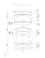
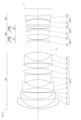
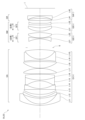
- FIG. 3 is a diagram showing a lens configuration of an optical system according to a first example.
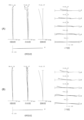
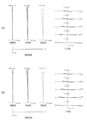
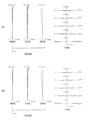
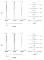
- FIGS. 2A and 2B are diagrams of various aberrations of the optical system according to the first example when focusing on infinity and when focusing on short distance, respectively.
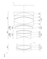
- FIG. 7 is a diagram showing a lens configuration of an optical system according to a second example.
- FIGS. 4A and 4B are diagrams of various aberrations of the optical system according to the second embodiment when focusing on infinity and when focusing on short distance, respectively. It is a figure which shows the lens structure of the optical system based on 3rd Example.
- FIGS. 6A and 6B are diagrams of various aberrations of the optical system according to the third embodiment when focusing on infinity and when focusing on short distance, respectively.
- FIGS. 8A and 8B are diagrams of various aberrations of the optical system according to the fourth example when focusing on infinity and when focusing on short distance, respectively. It is a figure which shows the lens structure of the optical system based on 5th Example. 10(A) and 10(B) are diagrams of various aberrations of the optical system according to the fifth embodiment when focusing on infinity and when focusing on short distance, respectively. It is a figure which shows the lens structure of the optical system based on 6th Example.
- FIGS. 12(A) and 12(B) are diagrams of various aberrations of the optical system according to the sixth embodiment when focusing on infinity and when focusing on short distance, respectively.
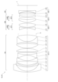
- FIGS. 14(A) and 14(B) are diagrams of various aberrations of the optical system according to the seventh embodiment when focusing on infinity and when focusing on short distance, respectively. It is a figure which shows the lens structure of the optical system based on 8th Example. 16(A) and 16(B) are diagrams of various aberrations of the optical system according to the eighth embodiment when focusing on infinity and when focusing on short distance, respectively.
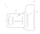
- FIG. 1 is a diagram showing the configuration of a camera including an optical system according to the present embodiment.
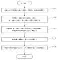
- 3 is a flowchart showing a method for manufacturing an optical system according to the present embodiment.
- this camera 1 includes a main body 2 and a photographic lens 3 attached to the main body 2.
- the main body 2 includes an image sensor 4, a main body control section (not shown) that controls the operation of the digital camera, and a liquid crystal screen 5.
- the photographic lens 3 includes an optical system OL consisting of a plurality of lens groups, and a lens position control mechanism (not shown) that controls the position of each lens group.
- the lens position control mechanism includes a sensor that detects the position of the lens group, a motor that moves the lens group back and forth along the optical axis, a control circuit that drives the motor, and the like.
- the light from the subject is collected by the optical system OL of the photographic lens 3 and reaches the image plane I of the image sensor 4.
- the light from the subject that has reached the image plane I is photoelectrically converted by the image sensor 4 and recorded in a memory (not shown) as digital image data.
- the digital image data recorded in the memory can be displayed on the liquid crystal screen 5 in response to user operations.
- this camera may be a mirrorless camera or a single-lens reflex camera with a quick return mirror.
- the optical system OL shown in FIG. 17 schematically shows the optical system provided in the photographing lens 3, and the lens configuration of the optical system OL is not limited to this configuration.
- the optical system OL (1) as an example of the optical system OL according to the present embodiment includes a front group GA, a middle group GM, and a rear group arranged in order from the object side along the optical axis. It consists of group GR.
- the intermediate group GM is composed of a first focusing lens group GF1 having a positive refractive power and a second focusing lens group GF2 having a positive refractive power, which are arranged in order from the object side along the optical axis. .
- the rear group GR includes a negative lens (L44) disposed closest to the image plane side of the rear group GR.
- the optical system OL satisfies the following conditional expressions (1) and (2). 0.01 ⁇ fF2/fF1 ⁇ 10.00...(1) 0.50 ⁇ Y/Bf ⁇ 5.00...(2)
- fF1 Focal length of the first focusing lens group
- GF1 Focal length of the second focusing lens group
- Y Image height of the optical system OL
- Bf Back focus of the optical system OL
- the optical system OL according to this embodiment may be the optical system OL (2) shown in FIG. 3, the optical system OL (3) shown in FIG. 5, or the optical system OL (4) shown in FIG. 7. Further, the optical system OL according to the present embodiment may be the optical system OL (5) shown in FIG. 9, the optical system OL (6) shown in FIG. 11, or the optical system OL (7) shown in FIG. , an optical system OL (8) shown in FIG. 15 may be used.
- Conditional expression (1) defines an appropriate relationship between the focal length of the second focusing lens group GF2 and the focal length of the first focusing lens group GF1. By satisfying conditional expression (1), it is possible to satisfactorily correct various aberrations such as coma aberration.
- conditional expression (1) If the value corresponding to conditional expression (1) exceeds the upper limit, the refractive power of the first focusing lens group GF1 becomes too strong, so it is necessary to correct spherical aberration and coma aberration when focusing on a close object. becomes difficult.
- the upper limit of conditional expression (1) is set to 8.50, 7.50, 7.00, 5.00, 4.00, 3.50, 2.50, 2.00, and further to 1.50. Therefore, the effects of this embodiment can be made more reliable.
- conditional expression (1) If the corresponding value of conditional expression (1) is below the lower limit value, the refractive power of the second focusing lens group GF2 becomes too strong, so coma aberration and field curvature when focusing on a close object are corrected. things become difficult.
- the lower limit of conditional expression (1) By setting the lower limit of conditional expression (1) to 0.05 and further to 0.09, the effects of this embodiment can be made more reliable.
- Conditional expression (2) defines an appropriate relationship between the image height of the optical system OL and the back focus of the optical system OL.
- the back focus of the optical system OL is the air-equivalent distance on the optical axis from the lens surface closest to the image plane of the optical system OL to the image plane I.
- the optical system OL further includes an aperture stop S and satisfies the following conditional expression (3).
- fSr Synthetic focal length of the lens placed closer to the image plane than the aperture stop S in the optical system OL in the infinity focusing state
- fSa Synthetic focal length of the lens placed closer to the object side than the aperture stop S in the optical system OL
- Conditional expression (3) is the composite focal length in the infinity focus state of the lens placed closer to the image plane than the aperture stop S in the optical system OL, and the composite focal length of the lens placed closer to the object side than the aperture stop S in the optical system OL. This defines an appropriate relationship between the lens and the composite focal length when the lens is focused at infinity.
- conditional expression (3) If the corresponding value of conditional expression (3) exceeds the upper limit, the refractive power of the lens placed closer to the object side than the aperture stop S in the optical system OL will become too strong, which will reduce spherical aberration, coma aberration, and curvature of field. It becomes difficult to make corrections.
- the upper limit of conditional expression (3) By setting the upper limit of conditional expression (3) to 3.50, 3.00, 2.50, or even 2.30, the effects of this embodiment can be made more reliable.
- conditional expression (3) If the corresponding value of conditional expression (3) is below the lower limit, the refractive power of the lens placed closer to the image plane than the aperture stop S in the optical system OL becomes too strong, resulting in spherical aberration, coma aberration, and curvature of field. It becomes difficult to make corrections.
- the lower limit of conditional expression (3) By setting the lower limit of conditional expression (3) to 0.13, and further to 0.18, the effects of this embodiment can be made more reliable.
- optical system OL it is desirable that the optical system OL according to this embodiment satisfy the following conditional expression (4). 0.05 ⁇ fF2/fA ⁇ 8.00...(4) However, fA: focal length of front group GA
- Conditional expression (4) defines an appropriate relationship between the focal length of the second focusing lens group GF2 and the focal length of the front group GA. By satisfying conditional expression (4), various aberrations such as coma aberration and curvature of field can be favorably corrected.
- conditional expression (4) If the corresponding value of conditional expression (4) exceeds the upper limit, the refractive power of the front group GA becomes too strong, making it difficult to correct spherical aberration, coma aberration, and curvature of field.
- the upper limit of conditional expression (4) By setting the upper limit of conditional expression (4) to 6.00, 5.00, 4.00, 3.00, 2.00, and even 1.50, the effect of this embodiment can be made more reliable. It can be done.
- conditional expression (4) If the corresponding value of conditional expression (4) is below the lower limit value, the refractive power of the second focusing lens group GF2 becomes too strong, so coma aberration and field curvature are corrected when focusing on a close object. things become difficult.
- the lower limit of conditional expression (4) By setting the lower limit of conditional expression (4) to 0.10, and further to 0.20, the effects of this embodiment can be made more reliable.
- optical system OL it is desirable that the optical system OL according to this embodiment satisfy the following conditional expression (5). 0.10 ⁇ (-fR)/fF2 ⁇ 8.00...(5)
- fR focal length of rear group GR
- Conditional expression (5) defines an appropriate relationship between the focal length of the rear group GR and the focal length of the second focusing lens group GF2. By satisfying conditional expression (5), comatic aberration and field curvature can be favorably corrected.
- conditional expression (5) If the value corresponding to conditional expression (5) exceeds the upper limit, the refractive power of the second focusing lens group GF2 becomes too strong, so comatic aberration and field curvature are corrected when focusing on a close object. things become difficult.
- the upper limit of conditional expression (5) By setting the upper limit of conditional expression (5) to 6.00, 5.00, 4.00, 3.00, and even 2.50, the effects of this embodiment can be made more reliable. can.
- conditional expression (5) If the corresponding value of conditional expression (5) is below the lower limit value, the refractive power of the rear group GR becomes too strong, making it difficult to correct coma aberration and curvature of field.
- the lower limit of conditional expression (5) By setting the lower limit of conditional expression (5) to 0.30, and further to 0.60, the effects of this embodiment can be made more reliable.
- optical system OL it is desirable that the optical system OL according to this embodiment satisfy the following conditional expression (6). 0.02 ⁇ fA/fF1 ⁇ 4.00 (6)
- fA focal length of front group GA
- Conditional expression (6) defines an appropriate relationship between the focal length of the front group GA and the focal length of the first focusing lens group GF1. By satisfying conditional expression (6), it is possible to satisfactorily correct various aberrations such as spherical aberration and coma aberration.
- conditional expression (6) If the corresponding value of conditional expression (6) exceeds the upper limit, the refractive power of the first focusing lens group GF1 becomes too strong, so it is necessary to correct spherical aberration and coma aberration when focusing on a close object. becomes difficult.
- the upper limit of conditional expression (6) By setting the upper limit of conditional expression (6) to 3.50, 3.00, 2.50, or even 2.00, the effects of this embodiment can be made more reliable.
- conditional expression (6) If the corresponding value of conditional expression (6) is below the lower limit, the refractive power of the front group GA becomes too strong, making it difficult to correct spherical aberration, coma aberration, and curvature of field.
- the lower limit of conditional expression (6) By setting the lower limit of conditional expression (6) to 0.05, and further to 0.08, the effects of this embodiment can be made more reliable.
- optical system OL it is desirable that the optical system OL according to this embodiment satisfy the following conditional expression (7). 0.10 ⁇ fF1/(-fR) ⁇ 8.00 (7)
- fR focal length of rear group GR
- Conditional expression (7) defines an appropriate relationship between the focal length of the first focusing lens group GF1 and the focal length of the rear group GR. By satisfying conditional expression (7), it is possible to satisfactorily correct various aberrations such as coma aberration.
- conditional expression (7) If the corresponding value of conditional expression (7) exceeds the upper limit, the refractive power of the rear group GR becomes too strong, making it difficult to correct coma aberration and curvature of field.
- the upper limit of conditional expression (7) By setting the upper limit of conditional expression (7) to 6.00, and further to 5.00, the effects of this embodiment can be made more reliable.
- conditional expression (7) If the corresponding value of conditional expression (7) is below the lower limit value, the refractive power of the first focusing lens group GF1 becomes too strong, so it is necessary to correct spherical aberration and coma aberration when focusing on a close object. becomes difficult.
- the lower limit of conditional expression (7) By setting the lower limit of conditional expression (7) to 0.20, and further to 0.30, the effects of this embodiment can be made more reliable.
- optical system OL it is desirable that the optical system OL according to this embodiment satisfy the following conditional expression (8). 0.10 ⁇ fA/(-fR) ⁇ 4.00...(8) However, fR: focal length of rear group GR
- Conditional expression (8) defines an appropriate relationship between the focal length of the front group GA and the focal length of the rear group GR. By satisfying conditional expression (8), various aberrations such as coma aberration and curvature of field can be favorably corrected.
- conditional expression (8) If the corresponding value of conditional expression (8) exceeds the upper limit, the refractive power of the rear group GR becomes too strong, making it difficult to correct coma aberration and curvature of field.
- the upper limit of conditional expression (8) By setting the upper limit of conditional expression (8) to 3.00, and further to 2.50, the effects of this embodiment can be made more reliable.
- conditional expression (8) If the corresponding value of conditional expression (8) is below the lower limit, the refractive power of the front group GA becomes too strong, making it difficult to correct spherical aberration, coma aberration, and curvature of field.
- the lower limit of conditional expression (8) By setting the lower limit of conditional expression (8) to 0.20, and further to 0.30, the effects of this embodiment can be made more reliable.
- optical system OL it is desirable that the optical system OL according to this embodiment satisfy the following conditional expression (9). 1.00 ⁇ f/Bf ⁇ 8.00...(9) However, f: focal length of optical system OL
- Conditional expression (9) defines an appropriate relationship between the focal length of the optical system OL and the back focus of the optical system OL. By satisfying conditional expression (9), it becomes possible to obtain an optical system that is small, bright, and has good optical performance. By setting the upper limit of conditional expression (9) to 6.00, and further to 4.50, the effects of this embodiment can be made more reliable. Further, by setting the lower limit value of conditional expression (9) to 1.50, and further to 2.50, the effects of this embodiment can be made more reliable.
- optical system OL it is desirable that the optical system OL according to this embodiment satisfy the following conditional expression (10). 0.50 ⁇ TL/f ⁇ 7.00 (10) However, f: Focal length of optical system OL TL: Total length of optical system OL
- Conditional expression (10) defines an appropriate relationship between the total length of the optical system OL and the focal length of the optical system OL.
- the total length of the optical system OL is the distance on the optical axis from the lens surface closest to the object side of the optical system OL to the image plane I (however, the total length is the distance from the lens surface closest to the image plane of the optical system OL The distance to the image plane I on the optical axis is air-equivalent distance).
- the optical system OL According to this embodiment satisfy the following conditional expression (11). 0.10 ⁇ fe/fR ⁇ 0.90 (11) However, fe: Focal length of the negative lens placed closest to the image plane in the rear group GR fR: Focal length of the rear group GR
- Conditional expression (11) defines an appropriate relationship between the focal length of the negative lens disposed closest to the image plane of the rear group GR and the focal length of the rear group GR. By satisfying conditional expression (11), various aberrations such as field curvature can be favorably corrected.
- conditional expression (11) If the corresponding value of conditional expression (11) exceeds the upper limit, the refractive power of the rear group GR becomes too strong, making it difficult to correct coma aberration and curvature of field.
- the upper limit of conditional expression (11) By setting the upper limit of conditional expression (11) to 0.85, and further to 0.75, the effects of this embodiment can be made more reliable.
- conditional expression (11) falls below the lower limit, the refractive power of the negative lens disposed closest to the image plane in the rear group GR becomes too strong, making it difficult to correct the curvature of field. .
- the lower limit of conditional expression (11) 0.15 and further to 0.20, the effects of this embodiment can be made more reliable.
- the optical system OL further includes an aperture stop S disposed between the front group GA and the intermediate group GM. This makes it possible to correct spherical aberration, coma aberration, and field curvature when focusing on a close object.
- the front group GA has positive refractive power. This makes it possible to correct spherical aberration, coma aberration, and field curvature.
- the rear group GR has negative refractive power. This makes it possible to correct comatic aberration and field curvature.
- the front group GA, intermediate group GM, and rear group GR are arranged in order from the object side along the optical axis (step ST1).
- a first focusing lens group GF1 having a positive refractive power and a second focusing lens group GF2 having a positive refractive power are arranged in order from the object side along the optical axis.
- Step ST2 the first focusing lens group GF1 and the second focusing lens group GF2 move along the optical axis with mutually different trajectories, and the front group GA and the rear group GR are placed on the image plane I.
- step ST3 Further, a negative lens is placed closest to the image plane of the rear group GR (step ST4). Then, each lens is arranged within the lens barrel so that at least the above conditional expressions (1) and (2) are satisfied (step ST5). According to such a manufacturing method, it is possible to manufacture an optical system that is small, bright, and has good optical performance.
- FIG. 4 is a cross-sectional view showing refractive power distribution.
- arrows indicate the direction of movement of each lens group along the optical axis when focusing from infinity to a close object. It shows.
- each lens group is designated by a combination of symbol G and a number
- each lens is designated by a combination of symbol L and a number.
- lens groups and the like are expressed using combinations of codes and numbers independently for each embodiment. Therefore, even if the same combination of symbols and numbers is used between the embodiments, it does not mean that they have the same configuration.
- Tables 1 to 8 are shown below, of which Table 1 is the first example, Table 2 is the second example, Table 3 is the third example, Table 4 is the fourth example, and Table 5 is the fourth example.
- Table 6 is a table showing each specification data of the sixth embodiment
- Table 7 is a table of the seventh embodiment
- Table 8 is a table showing each specification data of the eighth embodiment.
- f is the focal length of the entire lens system
- FNO is the F number
- ⁇ is the half angle of view (in degrees (degrees))
- Y is the image height.
- TL is the distance on the optical axis from the lens surface closest to the object side to the lens surface closest to the image plane of the optical system when focusing at infinity, plus Bf (back focus), and Bf is the distance when focusing at infinity. Indicates the distance on the optical axis from the lens surface closest to the image plane of the optical system to the image plane at focusing (air equivalent distance).
- fA indicates the focal length of the front group.
- fR indicates the focal length of the rear group.
- fF1 indicates the focal length of the first focusing lens group.
- fF2 indicates the focal length of the second focusing lens group.
- fSa indicates the composite focal length of a lens placed closer to the object side than the aperture stop in the optical system in the infinity focused state.
- fSr indicates the composite focal length of a lens placed closer to the image plane than the aperture stop in the optical system in a focused state at infinity.
- fe indicates the focal length of the negative lens disposed closest to the image plane in the rear group.
- the surface number indicates the order of the optical surfaces from the object side along the direction of propagation of the light ray
- R is the radius of curvature of each optical surface (the surface whose center of curvature is located on the image side).
- D is the surface spacing that is the distance on the optical axis from each optical surface to the next optical surface (or image surface)
- nd is the refractive index of the material of the optical member for the d-line
- ⁇ d is the optical The Abbe number based on the d-line of the material of the member is shown.
- the radius of curvature " ⁇ " indicates a plane or an aperture
- (diaphragm S) indicates an aperture diaphragm S, respectively.
- the description of the refractive index nd 1.00000 of air is omitted.
- the [Variable Interval Data] table shows the surface spacing at surface number i where the surface spacing is (Di) in the [Lens Specifications] table. Further, the [Variable Interval Data] table shows the surface spacing in the infinity focus state and the surface spacing in the close focus state.
- f indicates the focal length of the entire lens system
- ⁇ indicates the imaging magnification. Further, D0 indicates the distance from the object to the optical surface closest to the object in the optical system.
- the [Lens group data] table shows the starting surface (the surface closest to the object) and focal length of each lens group.
- the focal length f, radius of curvature R, surface spacing D, and other lengths are generally expressed in mm unless otherwise specified, but the optical system is proportionally enlarged. Alternatively, even if the optical performance is proportionally reduced, the same optical performance can be obtained, so the present invention is not limited to this.
- FIG. 1 is a diagram showing a lens configuration of an optical system according to a first embodiment.
- the optical system OL (1) according to the first embodiment includes a first lens group G1 having positive refractive power and a second lens group G2 having positive refractive power, which are arranged in order from the object side along the optical axis. , a third lens group G3 having a positive refractive power, and a fourth lens group G4 having a negative refractive power.
- the second lens group G2 and the third lens group G3 move toward the object along the optical axis with different trajectories (movements), and each adjacent lens group The interval between changes.
- the positions of the first lens group G1 and the fourth lens group G4 are fixed with respect to the image plane I.
- the sign (+) or (-) attached to each lens group symbol indicates the refractive power of each lens group, and this is the same in all the examples below.
- the aperture stop S is disposed between the first lens group G1 and the second lens group G2. During focusing, the position of the aperture stop S is fixed with respect to the image plane I.
- the first lens group G1 constitutes the front group GA
- the second lens group G2 and the third lens group G3 constitute the intermediate group GM
- the fourth lens group G4 constitutes the rear group GR.
- the second lens group G2 corresponds to the first focusing lens group GF1
- the third lens group G3 corresponds to the second focusing lens group GF2.
- the first lens group G1 is composed of a double-concave negative lens L11, a double-convex positive lens L12, and a negative meniscus lens L13 with a concave surface facing the object side, which are arranged in order from the object side along the optical axis. It consists of a cemented positive lens.
- the second lens group G2 includes a cemented negative lens in which a biconcave negative lens L21 and a positive meniscus lens L22 with a convex surface facing the object side are cemented, which are arranged in order from the object side along the optical axis, and a biconvex negative lens L21. It is composed of a positive lens L23 having a shape.
- the positive lens L23 is a hybrid lens configured by providing a resin layer on the image plane side surface of a glass lens body.
- the image plane side surface of the resin layer is an aspherical surface
- the positive lens L23 is a composite aspherical lens.
- surface number 10 is the object-side surface of the lens body
- surface number 11 is the image-side surface of the lens body
- the object-side surface of the resin layer (the surface where the two bond together).
- Number 12 indicates the surface of the resin layer on the image plane side.
- the third lens group G3 is composed of a biconvex positive lens L31.
- the positive lens L31 is a hybrid lens configured by providing a resin layer on the image plane side surface of a glass lens body.
- the image plane side surface of the resin layer is an aspherical surface
- the positive lens L31 is a composite aspherical lens.
- surface number 13 is the object-side surface of the lens body
- surface number 14 is the image-side surface of the lens body
- the object-side surface of the resin layer (the surface where the two bond together).
- Number 15 indicates the surface of the resin layer on the image plane side.
- the fourth lens group G4 includes a cemented positive lens in which a biconcave negative lens L41 and a biconvex positive lens L42 are cemented, which are arranged in order from the object side along the optical axis, and a biconcave negative lens. L43, and a plano-concave negative lens L44 with its plane facing the image plane side.
- An image plane I is arranged on the image side of the fourth lens group G4.
- Table 1 below lists the values of the specifications of the optical system according to the first example.
- FIG. 2(A) is a diagram of various aberrations of the optical system according to the first example when focusing at infinity.
- FIG. 2(B) is a diagram showing various aberrations of the optical system according to the first embodiment when focusing at a short distance.
- FNO indicates the F number
- Y indicates the image height.
- NA indicates the numerical aperture
- Y indicates the image height.
- spherical aberration diagrams show the F number or numerical aperture value corresponding to the maximum aperture
- astigmatism diagrams and distortion aberration diagrams each show the maximum image height
- coma aberration diagrams show the value of each image height. .
- the solid line indicates the sagittal image plane
- the broken line indicates the meridional image plane. Note that in the aberration diagrams of each example shown below, the same symbols as in this example are used, and overlapping explanations will be omitted.
- the optical system according to the first example has excellent imaging performance with various aberrations well corrected not only when focusing at infinity but also when focusing at close range. I understand that.
- FIG. 3 is a diagram showing a lens configuration of an optical system according to a second embodiment.
- the optical system OL (2) according to the second embodiment includes a first lens group G1 having positive refractive power and a second lens group G2 having positive refractive power, which are arranged in order from the object side along the optical axis. , a third lens group G3 having a positive refractive power, and a fourth lens group G4 having a negative refractive power.
- the second lens group G2 and the third lens group G3 move toward the object along the optical axis with different trajectories (movements), and each adjacent lens group The interval between changes. Note that during focusing, the positions of the first lens group G1 and the fourth lens group G4 are fixed with respect to the image plane I.
- the aperture stop S is disposed between the first lens group G1 and the second lens group G2. During focusing, the position of the aperture stop S is fixed with respect to the image plane I.
- the first lens group G1 constitutes the front group GA
- the second lens group G2 and the third lens group G3 constitute the intermediate group GM
- the fourth lens group G4 constitutes the rear group GR.
- the second lens group G2 corresponds to the first focusing lens group GF1
- the third lens group G3 corresponds to the second focusing lens group GF2.
- the first lens group G1 includes a positive meniscus lens L11 with a convex surface facing the object side, a positive meniscus lens L12 with a convex surface facing the object side, and a positive meniscus lens L12 with a convex surface facing the object side, which are arranged in order from the object side along the optical axis. and a negative meniscus lens L13.
- the positive meniscus lens L12 has an aspherical lens surface on the object side.
- the second lens group G2 includes a cemented negative lens in which a biconcave negative lens L21 and a positive meniscus lens L22 with a convex surface facing the object side are cemented, which are arranged in order from the object side along the optical axis, and a biconvex negative lens L21. It is composed of a positive lens L23 having a shape.
- the positive lens L23 is a hybrid lens configured by providing a resin layer on the image plane side surface of a glass lens body.
- the image plane side surface of the resin layer is an aspherical surface
- the positive lens L23 is a composite aspherical lens.
- surface number 11 is the object side surface of the lens body
- surface number 12 is the image side surface of the lens body
- the object side surface of the resin layer (the surface where both bond together)
- the surface Number 13 indicates the surface of the resin layer on the image plane side.
- the third lens group G3 is composed of a biconvex positive lens L31.
- the positive lens L31 is a hybrid lens configured by providing a resin layer on the image plane side surface of a glass lens body.
- the image plane side surface of the resin layer is an aspherical surface
- the positive lens L31 is a composite aspherical lens.
- surface number 14 is the object-side surface of the lens body
- surface number 15 is the image-side surface of the lens body
- the object-side surface of the resin layer (the surface where the two bond together).
- Number 16 indicates the image plane side surface of the resin layer.
- the fourth lens group G4 is a cemented positive lens in which a positive meniscus lens L41 with a concave surface facing the object side and a negative meniscus lens L42 with a concave surface facing the object side are cemented together, which are arranged in order from the object side along the optical axis. , a double-concave negative lens L43, and a plano-concave negative lens L44 with its plane facing toward the image plane.
- An image plane I is arranged on the image side of the fourth lens group G4.
- Table 2 below lists the values of the specifications of the optical system according to the second example.
- FIG. 4(A) is a diagram of various aberrations of the optical system according to the second example when focusing at infinity.
- FIG. 4(B) is a diagram showing various aberrations of the optical system according to the second embodiment when focusing at a short distance. From the various aberration diagrams, it can be seen that the optical system according to the second example has excellent imaging performance with various aberrations well corrected not only when focusing at infinity but also when focusing at close range. I understand that.
- FIG. 5 is a diagram showing a lens configuration of an optical system according to a third embodiment.
- the optical system OL (3) according to the third embodiment includes a first lens group G1 having positive refractive power and a second lens group G2 having positive refractive power, which are arranged in order from the object side along the optical axis. , a third lens group G3 having a positive refractive power, and a fourth lens group G4 having a negative refractive power.
- the second lens group G2 and the third lens group G3 move toward the object along the optical axis with different trajectories (movements), and each adjacent lens group The interval between changes. Note that during focusing, the positions of the first lens group G1 and the fourth lens group G4 are fixed with respect to the image plane I.
- the aperture stop S is disposed between the first lens group G1 and the second lens group G2. During focusing, the position of the aperture stop S is fixed with respect to the image plane I.
- the first lens group G1 constitutes the front group GA
- the second lens group G2 and the third lens group G3 constitute the intermediate group GM
- the fourth lens group G4 constitutes the rear group GR.
- the second lens group G2 corresponds to the first focusing lens group GF1
- the third lens group G3 corresponds to the second focusing lens group GF2.
- the first lens group G1 includes a plano-concave negative lens L11 with its plane facing the object side, which is arranged in order from the object side along the optical axis, a biconvex positive lens L12, and a biconcave negative lens L13. and a cemented positive lens.
- the second lens group G2 includes a cemented negative lens in which a biconcave negative lens L21 and a positive meniscus lens L22 with a convex surface facing the object side are cemented, which are arranged in order from the object side along the optical axis, and a biconvex negative lens L21. It is composed of a positive lens L23 having a shape.
- the positive lens L23 is a hybrid lens configured by providing a resin layer on the image plane side surface of a glass lens body.
- the image plane side surface of the resin layer is an aspherical surface
- the positive lens L23 is a composite aspherical lens.
- surface number 10 is the object-side surface of the lens body
- surface number 11 is the image-side surface of the lens body
- the object-side surface of the resin layer (the surface where the two bond together).
- Number 12 indicates the surface of the resin layer on the image plane side.
- the third lens group G3 is composed of a biconvex positive lens L31.
- the positive lens L31 is a hybrid lens configured by providing a resin layer on the image plane side surface of a glass lens body.
- the image plane side surface of the resin layer is an aspherical surface
- the positive lens L31 is a composite aspherical lens.
- surface number 13 is the object-side surface of the lens body
- surface number 14 is the image-side surface of the lens body
- the object-side surface of the resin layer (the surface where the two bond together).
- Number 15 indicates the surface of the resin layer on the image plane side.
- the fourth lens group G4 includes a cemented positive lens in which a biconcave negative lens L41 and a biconvex positive lens L42 are cemented together, arranged in order from the object side along the optical axis, and a cemented positive lens with a concave surface facing the object side. It consists of a negative meniscus lens L43 and a plano-concave negative lens L44 with its plane facing the image plane. An image plane I is arranged on the image side of the fourth lens group G4.
- Table 3 lists the values of the specifications of the optical system according to the third example.
- FIG. 6(A) is a diagram of various aberrations of the optical system according to the third example when focusing at infinity.
- FIG. 6(B) is a diagram showing various aberrations of the optical system according to the third embodiment when focusing at a short distance. From the various aberration diagrams, it can be seen that the optical system according to the third example has excellent imaging performance with various aberrations well corrected not only when focusing at infinity but also when focusing at close range. I understand that.
- FIG. 7 is a diagram showing a lens configuration of an optical system according to a fourth example.
- the optical system OL (4) according to the fourth embodiment includes a first lens group G1 having positive refractive power and a second lens group G2 having positive refractive power, which are arranged in order from the object side along the optical axis. , a third lens group G3 having a positive refractive power, and a fourth lens group G4 having a negative refractive power.
- the second lens group G2 and the third lens group G3 move along the optical axis toward the object side with different trajectories (movements), and each adjacent lens group The interval between changes. Note that during focusing, the positions of the first lens group G1 and the fourth lens group G4 are fixed with respect to the image plane I.
- the aperture stop S is disposed between the first lens group G1 and the second lens group G2. During focusing, the position of the aperture stop S is fixed with respect to the image plane I.
- the first lens group G1 constitutes the front group GA
- the second lens group G2 and the third lens group G3 constitute the intermediate group GM
- the fourth lens group G4 constitutes the rear group GR.
- the second lens group G2 corresponds to the first focusing lens group GF1
- the third lens group G3 corresponds to the second focusing lens group GF2.
- the first lens group G1 includes a negative meniscus lens L11 with a convex surface facing the object side, a negative meniscus lens L12 with a convex surface facing the object side, and a biconvex positive lens arranged in order from the object side along the optical axis.
- the negative meniscus lens L12 has an aspherical lens surface on the image plane side.
- the second lens group G2 is composed of a biconcave negative lens L21 and a biconvex positive lens L22, which are arranged in order from the object side along the optical axis.
- the third lens group G3 is composed of a positive meniscus lens L31 with a convex surface facing the object side and a positive meniscus lens L32 with a convex surface facing the object side, which are arranged in order from the object side along the optical axis.
- the positive meniscus lens L31 has an aspheric lens surface on the image plane side.
- the positive meniscus lens L32 has an aspherical lens surface on the image plane side.
- the fourth lens group G4 is composed of a positive meniscus lens L41 with a concave surface facing the object side and a biconcave negative lens L42, which are arranged in order from the object side along the optical axis.
- An image plane I is arranged on the image side of the fourth lens group G4.
- Table 4 lists the values of the specifications of the optical system according to the fourth example.
- FIG. 8(A) is a diagram of various aberrations of the optical system according to the fourth example when focusing at infinity.
- FIG. 8(B) is a diagram showing various aberrations of the optical system according to the fourth example when focusing at a short distance. From the various aberration diagrams, it can be seen that the optical system according to the fourth example has excellent imaging performance with various aberrations well corrected not only when focusing at infinity but also when focusing at close range. I understand that.
- FIG. 9 is a diagram showing a lens configuration of an optical system according to a fifth embodiment.
- the optical system OL (5) according to the fifth embodiment includes a first lens group G1 having positive refractive power and a second lens group G2 having positive refractive power, which are arranged in order from the object side along the optical axis. , a third lens group G3 having a positive refractive power, and a fourth lens group G4 having a negative refractive power.
- the second lens group G2 and the third lens group G3 move toward the object along the optical axis with different trajectories (movements), and each adjacent lens group The interval between changes. Note that during focusing, the positions of the first lens group G1 and the fourth lens group G4 are fixed with respect to the image plane I.
- the aperture stop S is disposed between the first lens group G1 and the second lens group G2. During focusing, the position of the aperture stop S is fixed with respect to the image plane I.
- the first lens group G1 constitutes the front group GA
- the second lens group G2 and the third lens group G3 constitute the intermediate group GM
- the fourth lens group G4 constitutes the rear group GR.
- the second lens group G2 corresponds to the first focusing lens group GF1
- the third lens group G3 corresponds to the second focusing lens group GF2.
- the first lens group G1 includes a negative meniscus lens L11 with a convex surface facing the object side, a negative meniscus lens L12 with a convex surface facing the object side, and a biconvex positive lens arranged in order from the object side along the optical axis.
- the negative meniscus lens L12 has an aspherical lens surface on the image plane side.
- the second lens group G2 is composed of a biconcave negative lens L21 and a biconvex positive lens L22, which are arranged in order from the object side along the optical axis.
- the third lens group G3 includes a cemented positive lens in which a biconvex positive lens L31 and a biconcave negative lens L32 are cemented, which are arranged in order from the object side along the optical axis, and a cemented positive lens with a concave surface facing the object side. and a negative meniscus lens L33.
- the negative meniscus lens L33 has aspherical lens surfaces on both sides.
- the fourth lens group G4 is composed of a positive meniscus lens L41 with a concave surface facing the object side and a biconcave negative lens L42, which are arranged in order from the object side along the optical axis.
- An image plane I is arranged on the image side of the fourth lens group G4.
- Table 5 lists the values of the specifications of the optical system according to the fifth example.
- FIG. 10(A) is a diagram of various aberrations of the optical system according to the fifth example when focusing at infinity.
- FIG. 10(B) is a diagram showing various aberrations of the optical system according to the fifth embodiment when focusing at a short distance. From the various aberration diagrams, it can be seen that the optical system according to the fifth example has excellent imaging performance with various aberrations well corrected not only when focusing at infinity but also when focusing at close range. I understand that.
- FIG. 11 is a diagram showing a lens configuration of an optical system according to a sixth embodiment.
- the optical system OL (6) according to the sixth embodiment includes a first lens group G1 having positive refractive power and a second lens group G2 having positive refractive power, which are arranged in order from the object side along the optical axis. , a third lens group G3 having a positive refractive power, and a fourth lens group G4 having a negative refractive power.
- the second lens group G2 and the third lens group G3 move toward the object along the optical axis with different trajectories (movements), and each adjacent lens group The interval between changes. Note that during focusing, the positions of the first lens group G1 and the fourth lens group G4 are fixed with respect to the image plane I.
- the aperture stop S is disposed between the first lens group G1 and the second lens group G2. During focusing, the position of the aperture stop S is fixed with respect to the image plane I.
- the first lens group G1 constitutes the front group GA
- the second lens group G2 and the third lens group G3 constitute the intermediate group GM
- the fourth lens group G4 constitutes the rear group GR.
- the second lens group G2 corresponds to the first focusing lens group GF1
- the third lens group G3 corresponds to the second focusing lens group GF2.
- the first lens group G1 includes a negative meniscus lens L11 with a convex surface facing the object side, which is arranged in order from the object side along the optical axis, a biconvex positive lens L12, and a biconcave negative lens L13 cemented together.
- a cemented negative lens in which a double-concave negative lens L14 and a positive meniscus lens L15 with a convex surface facing the object side are cemented together, a double-convex positive lens L16 with a concave surface facing the object side, and a double-convex positive lens L16 with a concave surface facing the object side.
- the second lens group G2 includes a negative meniscus lens L21 with a concave surface facing the object side, a positive biconvex lens L22, and a negative meniscus lens L22 with a concave surface facing the object side, which are arranged in order from the object side along the optical axis. It is composed of a lens L23. In the negative meniscus lens L23, both lens surfaces are aspheric.
- the third lens group G3 is composed of a positive meniscus lens L31 with a concave surface facing the object side and a negative meniscus lens L32 with a concave surface facing the object side, which are arranged in order from the object side along the optical axis.
- the positive meniscus lens L31 has an aspheric lens surface on the image plane side.
- the negative meniscus lens L32 has an aspherical lens surface on the object side.
- the fourth lens group G4 is composed of a cemented negative lens in which a positive meniscus lens L41 with a concave surface facing the object side and a biconcave negative lens L42 are cemented in order from the object side along the optical axis.
- An image plane I is arranged on the image side of the fourth lens group G4.
- Table 6 lists the values of the specifications of the optical system according to the sixth example.
- FIG. 12(A) is a diagram of various aberrations of the optical system according to the sixth embodiment when focusing at infinity.
- FIG. 12(B) is a diagram showing various aberrations of the optical system according to the sixth embodiment when focusing at a short distance. From the various aberration diagrams, it can be seen that the optical system according to the sixth embodiment has excellent imaging performance with various aberrations well corrected not only when focusing at infinity but also when focusing at close range. I understand that.
- FIG. 13 is a diagram showing a lens configuration of an optical system according to a seventh embodiment.
- the optical system OL (7) according to the seventh embodiment includes a first lens group G1 having positive refractive power and a second lens group G2 having positive refractive power, which are arranged in order from the object side along the optical axis. , a third lens group G3 having a positive refractive power, and a fourth lens group G4 having a negative refractive power.
- the second lens group G2 and the third lens group G3 move toward the object along the optical axis with different trajectories (movements), and each adjacent lens group The interval between changes. Note that during focusing, the positions of the first lens group G1 and the fourth lens group G4 are fixed with respect to the image plane I.
- the aperture stop S is disposed between the first lens group G1 and the second lens group G2. During focusing, the position of the aperture stop S is fixed with respect to the image plane I.
- the first lens group G1 constitutes the front group GA
- the second lens group G2 and the third lens group G3 constitute the intermediate group GM
- the fourth lens group G4 constitutes the rear group GR.
- the second lens group G2 corresponds to the first focusing lens group GF1
- the third lens group G3 corresponds to the second focusing lens group GF2.
- the first lens group G1 includes a negative meniscus lens L11 with a convex surface facing the object side, a negative meniscus lens L12 with a convex surface facing the object side, and a negative meniscus lens L12 with a convex surface facing the object side, which are arranged in order from the object side along the optical axis.
- a cemented positive lens in which a positive meniscus lens L13 is cemented; a cemented negative lens in which a biconvex positive lens L14 and a biconcave negative lens L15 are cemented; a biconcave negative lens L16; It is composed of a convex positive lens L17, a biconvex positive lens L18, and a cemented negative lens in which a biconcave negative lens L19 and a biconvex positive lens L110 are cemented.
- the second lens group G2 is composed of a negative meniscus lens L21 with a concave surface facing the object side and a biconvex positive lens L22, which are arranged in order from the object side along the optical axis.
- the third lens group G3 is composed of a biconcave negative lens L31 and a biconvex positive lens L32, which are arranged in order from the object side along the optical axis.
- the negative lens L31 has an aspherical lens surface on the image plane side.
- the positive lens L32 has aspherical lens surfaces on both sides.
- the fourth lens group G4 is composed of a biconvex positive lens L41 and a biconcave negative lens L42, which are arranged in order from the object side along the optical axis.
- An image plane I is arranged on the image side of the fourth lens group G4.
- Table 7 lists the values of the specifications of the optical system according to the seventh example.
- FIG. 14(A) is a diagram showing various aberrations of the optical system according to the seventh embodiment when focusing at infinity.
- FIG. 14(B) is a diagram showing various aberrations of the optical system according to the seventh embodiment when focusing at a short distance. From the various aberration diagrams, it can be seen that the optical system according to the seventh embodiment has excellent imaging performance with various aberrations well corrected not only when focusing at infinity but also when focusing at close range. I understand that.
- FIG. 15 is a diagram showing a lens configuration of an optical system according to the eighth embodiment.
- the optical system OL (8) according to the eighth embodiment includes a first lens group G1 having positive refractive power and a second lens group G2 having positive refractive power, which are arranged in order from the object side along the optical axis. , a third lens group G3 having a positive refractive power, and a fourth lens group G4 having a negative refractive power.
- the second lens group G2 and the third lens group G3 move toward the object along the optical axis with different trajectories (movements), and each adjacent lens group The interval between changes. Note that during focusing, the positions of the first lens group G1 and the fourth lens group G4 are fixed with respect to the image plane I.
- the aperture stop S is disposed between the first lens group G1 and the second lens group G2. During focusing, the position of the aperture stop S is fixed with respect to the image plane I.
- the first lens group G1 constitutes the front group GA
- the second lens group G2 and the third lens group G3 constitute the intermediate group GM
- the fourth lens group G4 constitutes the rear group GR.
- the second lens group G2 corresponds to the first focusing lens group GF1
- the third lens group G3 corresponds to the second focusing lens group GF2.
- the first lens group G1 includes a negative meniscus lens L11 with a convex surface facing the object side, a negative meniscus lens L12 with a convex surface facing the object side, and a negative meniscus lens L12 with a convex surface facing the object side, which are arranged in order from the object side along the optical axis.
- a cemented positive lens in which a positive meniscus lens L13 with a convex surface facing the object side and a negative meniscus lens L14 with a convex surface facing the object side are cemented, and a cemented negative lens in which a biconcave negative lens L15 and a biconvex positive lens L16 are cemented together.
- the negative meniscus lens L12 has an aspherical lens surface on the image plane side.
- the second lens group G2 is composed of a biconcave negative lens L21 and a biconvex positive lens L22, which are arranged in order from the object side along the optical axis.
- the third lens group G3 is composed of a positive meniscus lens L31 with a convex surface facing the object side and a biconvex positive lens L32, which are arranged in order from the object side along the optical axis.
- the positive meniscus lens L31 has an aspheric lens surface on the image plane side.
- the positive lens L32 has an aspherical lens surface on the image plane side.
- the fourth lens group G4 is composed of a positive meniscus lens L41 with a concave surface facing the object side and a negative meniscus lens L42 with a concave surface facing the object side, which are arranged in order from the object side along the optical axis.
- An image plane I is arranged on the image side of the fourth lens group G4.
- Table 8 lists the values of the specifications of the optical system according to the eighth example.
- FIG. 16(A) is a diagram showing various aberrations of the optical system according to the eighth embodiment when focusing on infinity.
- FIG. 16(B) is a diagram showing various aberrations of the optical system according to the eighth embodiment when focusing at a short distance. From the various aberration diagrams, the optical system according to the eighth example has excellent imaging performance with various aberrations well corrected not only when focusing at infinity but also when focusing at close range. I understand that.
- Conditional expression (1) 0.01 ⁇ fF2/fF1 ⁇ 10.00
- Conditional expression (2) 0.50 ⁇ Y/Bf ⁇ 5.00
- Conditional expression (3) 0.05 ⁇ fSr/fSa ⁇ 4.00
- Conditional expression (4) 0.05 ⁇ fF2/fA ⁇ 8.00
- Conditional expression (5) 0.10 ⁇ (-fR)/fF2 ⁇ 8.00
- Conditional expression (6) 0.02 ⁇ fA/fF1 ⁇ 4.00
- Conditional expression (7) 0.10 ⁇ fF1/(-fR) ⁇ 8.00
- Conditional expression (8) 0.10 ⁇ fA/(-fR) ⁇ 4.00
- Conditional expression (9) 1.00 ⁇ f/Bf ⁇ 8.00
- Conditional expression (10) 0.50 ⁇ TL/f ⁇ 7.00
- Conditional expression (11) 0.10 ⁇ fe/fR ⁇ 0.90
- a four-group configuration is shown as an example of the optical system of this embodiment, the present application is not limited to this, and optical systems with other group configurations (for example, five groups, six groups, seven groups, etc.) may be configured. You can also do that.
- a configuration may be adopted in which a lens or lens group is added to the closest to the object side or the closest to the image plane of the optical system of this embodiment.
- a configuration may also be adopted in which a lens or lens group is added between the first focusing lens group and the second focusing lens group in the intermediate group of the optical system of this embodiment.
- the lens group refers to a portion having at least one lens separated by an air gap that changes during focusing.
- Corrects image blur caused by camera shake by moving the lens group or partial lens group so that it has a component perpendicular to the optical axis, or rotating (swinging) it in a plane that includes the optical axis. It can also be used as an anti-vibration lens group.
- the lens surface may be formed as a spherical surface, a flat surface, or an aspherical surface. It is preferable that the lens surface is spherical or flat because it facilitates lens processing and assembly adjustment and prevents deterioration of optical performance due to errors in processing and assembly adjustment. Further, even if the image plane shifts, there is little deterioration in depiction performance, which is preferable.
- the aspherical surface can be an aspherical surface made by grinding, a glass molded aspherical surface made by molding glass into an aspherical shape, or a composite aspherical surface made by molding resin into an aspherical shape on the glass surface. Either is fine.
- the lens surface may be a diffractive surface, and the lens may be a gradient index lens (GRIN lens) or a plastic lens.
- the aperture diaphragm is preferably arranged between the first lens group constituting the front group and the second lens group constituting the intermediate group. You may substitute that role. Further, the first focusing lens group may be arranged opposite to the image plane side of the aperture stop.
- Each lens surface may be coated with an antireflection film that has high transmittance over a wide wavelength range in order to reduce flare and ghosting and achieve optical performance with high contrast.
Landscapes
- Physics & Mathematics (AREA)
- General Physics & Mathematics (AREA)
- Optics & Photonics (AREA)
- Lenses (AREA)
Abstract
Description
0.01<fF2/fF1<10.00
0.50<Y/Bf<5.00
但し、fF1:前記第1合焦レンズ群の焦点距離
fF2:前記第2合焦レンズ群の焦点距離
Y:前記光学系の像高
Bf:前記光学系のバックフォーカス
0.01<fF2/fF1<10.00
0.50<Y/Bf<5.00
但し、fF1:前記第1合焦レンズ群の焦点距離
fF2:前記第2合焦レンズ群の焦点距離
Y:前記光学系の像高
Bf:前記光学系のバックフォーカス
0.01<fF2/fF1<10.00 ・・・(1)
0.50<Y/Bf<5.00 ・・・(2)
但し、fF1:第1合焦レンズ群GF1の焦点距離
fF2:第2合焦レンズ群GF2の焦点距離
Y:光学系OLの像高
Bf:光学系OLのバックフォーカス
0.05<fSr/fSa<4.00 ・・・(3)
但し、fSr:光学系OLにおける開口絞りSよりも像面側に配置されたレンズの無限遠合焦状態における合成焦点距離
fSa:光学系OLにおける開口絞りSよりも物体側に配置されたレンズの無限遠合焦状態における合成焦点距離
0.05<fF2/fA<8.00 ・・・(4)
但し、fA:前群GAの焦点距離
0.10<(-fR)/fF2<8.00 ・・・(5)
但し、fR:後群GRの焦点距離
0.02<fA/fF1<4.00 ・・・(6)
但し、fA:前群GAの焦点距離
0.10<fF1/(-fR)<8.00 ・・・(7)
但し、fR:後群GRの焦点距離
0.10<fA/(-fR)<4.00 ・・・(8)
但し、fR:後群GRの焦点距離
1.00<f/Bf<8.00 ・・・(9)
但し、f:光学系OLの焦点距離
0.50<TL/f<7.00 ・・・(10)
但し、f:光学系OLの焦点距離
TL:光学系OLの全長
0.10<fe/fR<0.90 ・・・(11)
但し、fe:後群GRの最も像面側に配置された負レンズの焦点距離
fR:後群GRの焦点距離
第1実施例について、図1~図2および表1を用いて説明する。図1は、第1実施例に係る光学系のレンズ構成を示す図である。第1実施例に係る光学系OL(1)は、光軸に沿って物体側から順に並んだ、正の屈折力を有する第1レンズ群G1と、正の屈折力を有する第2レンズ群G2と、正の屈折力を有する第3レンズ群G3と、負の屈折力を有する第4レンズ群G4とから構成される。無限遠物体から近距離物体への合焦の際、第2レンズ群G2と第3レンズ群G3とが異なる軌跡(移動量)で光軸に沿って物体側へ移動し、隣り合う各レンズ群の間隔が変化する。なお、合焦の際、第1レンズ群G1および第4レンズ群G4は、像面Iに対して位置が固定される。各レンズ群記号に付けている符号(+)もしくは(-)は各レンズ群の屈折力を示し、このことは以下の全ての実施例でも同様である。
[全体諸元]
f=36.050 FNO=1.442
ω=31.814 Y=20.374
TL=83.685 Bf=12.113
fA=154.383 fR=-70.566
fF1=150.000 fF2=42.786
fSa=154.383 fSr=41.385
fe=-49.090
[レンズ諸元]
面番号 R D nd νd
1 -84.278 1.000 1.48749 70.31
2 34.272 0.582
3 42.331 6.737 1.83481 42.73
4 -39.159 0.900 1.76182 26.58
5 -167.335 1.600
6 ∞ (D6) (絞りS)
7 -23.995 0.900 1.64769 33.73
8 28.408 5.263 1.83481 42.73
9 214.240 0.100
10 69.377 5.846 1.83481 42.73
11 -52.510 0.100 1.56093 36.64
12* -50.272 (D12)
13 133.009 7.274 1.77250 49.62
14 -47.184 0.100 1.56093 36.64
15* -41.494 (D15)
16 -101.299 1.000 1.68893 31.16
17 37.985 11.824 1.83481 42.73
18 -43.191 0.100
19 -79.644 1.000 1.78472 25.64
20 863.090 6.024
21 -30.438 1.300 1.62004 36.40
22 ∞ Bf
[非球面データ]
第12面
κ=1.0000,A4=9.82707E-06,A6=8.10431E-09,A8=-4.53816E-11,A10=8.08855E-14
第15面
κ=1.0000,A4=7.20448E-06,A6=3.36893E-10,A8=3.34430E-11,A10=-3.62441E-14
[可変間隔データ]
無限遠合焦状態 近距離合焦状態
f=36.050 β=-0.03333
D0 ∞ 1073.885
D6 13.904 12.690
D12 4.519 4.847
D15 1.500 2.386
Bf 12.113 12.113
[レンズ群データ]
群 始面 焦点距離
G1 1 154.383
G2 7 150.000
G3 13 42.786
G4 16 -70.566
第2実施例について、図3~図4および表2を用いて説明する。図3は、第2実施例に係る光学系のレンズ構成を示す図である。第2実施例に係る光学系OL(2)は、光軸に沿って物体側から順に並んだ、正の屈折力を有する第1レンズ群G1と、正の屈折力を有する第2レンズ群G2と、正の屈折力を有する第3レンズ群G3と、負の屈折力を有する第4レンズ群G4とから構成される。無限遠物体から近距離物体への合焦の際、第2レンズ群G2と第3レンズ群G3とが異なる軌跡(移動量)で光軸に沿って物体側へ移動し、隣り合う各レンズ群の間隔が変化する。なお、合焦の際、第1レンズ群G1および第4レンズ群G4は、像面Iに対して位置が固定される。
[全体諸元]
f=48.500 FNO=1.442
ω=24.256 Y=21.413
TL=92.309 Bf=12.113
fA=144.537 fR=-64.985
fF1=141.932 fF2=42.786
fSa=144.537 fSr=45.388
fe=-398.038
[レンズ諸元]
面番号 R D nd νd
1 44.354 3.671 1.83481 42.73
2 68.031 2.679
3* 30.946 5.657 1.83481 42.73
4 119.179 0.686
5 456.720 0.900 1.59270 35.27
6 23.170 5.704
7 ∞ (D7) (絞りS)
8 -19.295 0.900 1.64769 33.72
9 24.301 6.226 1.83481 42.73
10 222.101 0.100
11 51.221 7.224 1.77250 49.62
12 -44.866 0.100 1.56093 36.64
13* -44.287 (D13)
14 51.773 6.423 1.77250 49.62
15 -154.916 0.100 1.56093 36.64
16* -74.031 (D16)
17 -510.487 12.769 1.85026 32.35
18 -20.236 1.000 1.90265 35.73
19 -61.076 0.100
20 -98.851 1.024 1.75520 27.57
21 48.753 4.694
22 -235.917 1.300 1.59270 35.27
23 ∞ Bf
[非球面データ]
第3面
κ=1.0000,A4=1.39886E-06,A6=7.46585E-09,A8=-1.84946E-11,A10=7.06419E-14
第13面
κ=1.0000,A4=6.25043E-06,A6=7.63434E-09,A8=-2.42103E-12,A10=2.61079E-14
第16面
κ=1.0000,A4=1.51632E-05,A6=-2.12876E-09,A8=3.12457E-11,A10=-4.64496E-14
[可変間隔データ]
無限遠合焦状態 近距離合焦状態
f=48.500 β=-0.03333
D0 ∞ 1427.370
D7 12.239 11.399
D13 5.200 4.948
D16 1.500 2.591
Bf 12.113 12.113
[レンズ群データ]
群 始面 焦点距離
G1 1 144.537
G2 8 141.932
G3 14 42.786
G4 17 -64.985
第3実施例について、図5~図6および表3を用いて説明する。図5は、第3実施例に係る光学系のレンズ構成を示す図である。第3実施例に係る光学系OL(3)は、光軸に沿って物体側から順に並んだ、正の屈折力を有する第1レンズ群G1と、正の屈折力を有する第2レンズ群G2と、正の屈折力を有する第3レンズ群G3と、負の屈折力を有する第4レンズ群G4とから構成される。無限遠物体から近距離物体への合焦の際、第2レンズ群G2と第3レンズ群G3とが異なる軌跡(移動量)で光軸に沿って物体側へ移動し、隣り合う各レンズ群の間隔が変化する。なお、合焦の際、第1レンズ群G1および第4レンズ群G4は、像面Iに対して位置が固定される。
[全体諸元]
f=36.050 FNO=1.442
ω=31.808 Y=20.358
TL=80.563 Bf=12.113
fA=175.868 fR=-103.535
fF1=100.040 fF2=50.621
fSa=175.868 fSr=38.887
fe=-55.498
[レンズ諸元]
面番号 R D nd νd
1 ∞ 1.000 1.48749 70.32
2 27.539 0.516
3 31.701 6.527 1.83481 42.73
4 -58.413 0.900 1.72825 28.38
5 142.453 2.116
6 ∞ (D6) (絞りS)
7 -23.996 0.900 1.59270 35.27
8 27.203 5.321 1.83481 42.73
9 403.040 0.124
10 75.848 5.128 1.83481 42.73
11 -58.068 0.100 1.56093 36.64
12* -54.564 (D12)
13 1598.814 5.843 1.75500 52.34
14 -40.976 0.100 1.56093 36.64
15* -38.468 (D15)
16 -119.723 1.000 1.72825 28.38
17 34.445 12.585 1.90265 35.73
18 -36.878 0.100
19 -43.561 2.607 1.84666 23.80
20 -236.442 4.820
21 -32.894 1.300 1.59270 35.27
22 ∞ Bf
[非球面データ]
第12面
κ=1.0000,A4=1.47674E-05,A6=-1.08656E-08,A8=8.95106E-12,A10=-3.68687E-15
第15面
κ=1.0000,A4=4.77686E-06,A6=1.19495E-08,A8=1.37062E-11,A10=3.29111E-14
[可変間隔データ]
無限遠合焦状態 近距離合焦状態
f=36.050 β=-0.03333
D0 ∞ 1081.803
D6 12.622 10.849
D12 3.342 4.228
D15 1.500 2.387
Bf 12.113 12.113
[レンズ群データ]
群 始面 焦点距離
G1 1 175.868
G2 7 100.040
G3 13 50.621
G4 16 -103.535
第4実施例について、図7~図8および表4を用いて説明する。図7は、第4実施例に係る光学系のレンズ構成を示す図である。第4実施例に係る光学系OL(4)は、光軸に沿って物体側から順に並んだ、正の屈折力を有する第1レンズ群G1と、正の屈折力を有する第2レンズ群G2と、正の屈折力を有する第3レンズ群G3と、負の屈折力を有する第4レンズ群G4とから構成される。無限遠物体から近距離物体への合焦の際、第2レンズ群G2と第3レンズ群G3とが異なる軌跡(移動量)で光軸に沿って物体側へ移動し、隣り合う各レンズ群の間隔が変化する。なお、合焦の際、第1レンズ群G1および第4レンズ群G4は、像面Iに対して位置が固定される。
[全体諸元]
f=34.301 FNO=1.230
ω=32.681 Y=21.600
TL=145.455 Bf=11.456
fA=60.284 fR=-155.922
fF1=493.944 fF2=77.173
fSa=60.284 fSr=87.232
fe=-52.564
[レンズ諸元]
面番号 R D nd νd
1 96.047 2.000 1.48749 70.31
2 28.087 9.219
3 66.416 1.800 1.58887 61.13
4* 42.041 2.388
5 47.837 8.233 2.00100 29.12
6 -645.006 1.500 1.49782 82.57
7 35.910 11.438
8 -33.782 1.500 1.85451 25.15
9 80.983 5.585 1.56732 42.58
10 -217.995 0.200
11 237.343 8.059 2.00069 25.46
12 -51.294 0.200
13 44.432 10.369 1.59349 67.00
14 -144.859 2.518
15 -99.402 1.500 1.69895 30.13
16 27.200 14.331 1.59319 67.90
17 -86.856 2.000
18 ∞ (D18) (絞りS)
19 -38.048 1.300 1.68376 37.64
20 178.836 0.200
21 41.104 9.000 1.59349 67.00
22 -68.514 (D22)
23 36.893 6.200 1.85108 40.12
24* 75.937 4.486
25 157.349 2.500 1.77387 47.25
26* 161.771 (D26)
27 -597.200 3.598 1.94595 17.98
28 -68.766 1.916
29 -40.274 1.500 1.73037 32.23
30 834.207 Bf
[非球面データ]
第4面
κ=1.0000,A4=-1.39004E-06,A6=-9.76153E-10,A8=-1.35116E-12,A10=-7.50960E-16
第24面
κ=1.0000,A4=-4.67477E-06,A6=-5.48120E-09,A8=3.46635E-11,A10=-1.11525E-14
第26面
κ=1.0000,A4=2.09207E-05,A6=2.10855E-08,A8=-1.68530E-11,A10=-2.78769E-14
[可変間隔データ]
無限遠合焦状態 近距離合焦状態
f=34.301 β=-0.03333
D0 ∞ 993.600
D18 13.152 11.783
D22 2.047 2.000
D26 5.262 6.678
Bf 11.456 11.456
[レンズ群データ]
群 始面 焦点距離
G1 1 60.284
G2 19 493.944
G3 23 77.173
G4 27 -155.922
第5実施例について、図9~図10および表5を用いて説明する。図9は、第5実施例に係る光学系のレンズ構成を示す図である。第5実施例に係る光学系OL(5)は、光軸に沿って物体側から順に並んだ、正の屈折力を有する第1レンズ群G1と、正の屈折力を有する第2レンズ群G2と、正の屈折力を有する第3レンズ群G3と、負の屈折力を有する第4レンズ群G4とから構成される。無限遠物体から近距離物体への合焦の際、第2レンズ群G2と第3レンズ群G3とが異なる軌跡(移動量)で光軸に沿って物体側へ移動し、隣り合う各レンズ群の間隔が変化する。なお、合焦の際、第1レンズ群G1および第4レンズ群G4は、像面Iに対して位置が固定される。
[全体諸元]
f=34.300 FNO=1.230
ω=32.676 Y=21.600
TL=145.455 Bf=11.455
fA=65.214 fR=-165.983
fF1=629.134 fF2=70.033
fSa=65.214 fSr=80.285
fe=-56.319
[レンズ諸元]
面番号 R D nd νd
1 72.093 2.000 1.48749 70.31
2 27.081 11.466
3 105.428 1.800 1.51680 64.13
4* 49.653 1.202
5 47.334 7.850 2.00100 29.12
6 -2063.273 1.500 1.49782 82.57
7 34.755 11.769
8 -32.107 1.500 1.85451 25.15
9 82.520 5.950 1.67003 47.14
10 -198.954 0.200
11 391.739 7.906 2.00069 25.46
12 -48.789 0.200
13 41.194 11.022 1.59349 67.00
14 -135.101 1.669
15 -112.838 1.500 1.73037 32.23
16 27.200 13.277 1.59319 67.90
17 -122.895 2.000
18 ∞ (D18) (絞りS)
19 -42.056 1.300 1.68376 37.64
20 240.838 0.200
21 38.726 7.500 1.59319 67.90
22 -118.915 (D22)
23 42.490 7.198 1.83481 42.73
24 -124.265 1.500 1.68376 37.64
25 96.988 5.998
26* -257.390 2.500 1.77387 47.25
27* -264.366 (D27)
28 -531.885 3.492 1.94595 17.98
29 -71.866 1.741
30 -43.260 1.500 1.73037 32.23
31 848.999 Bf
[非球面データ]
第4面
κ=1.0000,A4=-1.34774E-06,A6=-9.46928E-10,A8=-1.46439E-12,A10=-3.40961E-16
第26面
κ=1.0000,A4=-7.46350E-06,A6=6.20342E-08,A8=-1.63956E-10,A10=4.03734E-14
第27面
κ=1.0000,A4=9.35182E-06,A6=7.30804E-08,A8=-1.33669E-10,A10=1.93285E-14
[可変間隔データ]
無限遠合焦状態 近距離合焦状態
f=34.300 β=-0.03333
D0 ∞ 994.412
D18 12.611 11.246
D22 2.244 2.268
D27 3.404 4.744
Bf 11.455 11.455
[レンズ群データ]
群 始面 焦点距離
G1 1 65.214
G2 19 629.134
G3 23 70.033
G4 27 -165.983
第6実施例について、図11~図12および表6を用いて説明する。図11は、第6実施例に係る光学系のレンズ構成を示す図である。第6実施例に係る光学系OL(6)は、光軸に沿って物体側から順に並んだ、正の屈折力を有する第1レンズ群G1と、正の屈折力を有する第2レンズ群G2と、正の屈折力を有する第3レンズ群G3と、負の屈折力を有する第4レンズ群G4とから構成される。無限遠物体から近距離物体への合焦の際、第2レンズ群G2と第3レンズ群G3とが異なる軌跡(移動量)で光軸に沿って物体側へ移動し、隣り合う各レンズ群の間隔が変化する。なお、合焦の際、第1レンズ群G1および第4レンズ群G4は、像面Iに対して位置が固定される。
[全体諸元]
f=34.300 FNO=1.228
ω=32.697 Y=21.600
TL=155.455 Bf=11.455
fA=75.723 fR=-60.553
fF1=69.782 fF2=58.312
fSa=75.723 fSr=61.522
fe=-26.934
[レンズ諸元]
面番号 R D nd νd
1 81.239 2.000 1.59349 67.00
2 29.403 11.650
3 97.417 9.313 1.90265 35.77
4 -66.592 1.500 1.51742 52.20
5 37.688 11.679
6 -36.576 3.997 1.73037 32.23
7 57.862 5.275 1.94595 17.98
8 437.731 0.200
9 137.189 14.813 1.84850 43.79
10 -31.982 1.500 1.85451 25.15
11 -58.341 0.200
12 50.708 7.542 1.59319 67.90
13 173.475 0.200
14 50.175 13.955 1.59319 67.90
15 -45.041 1.500 1.64769 33.73
16 49.712 5.575
17 ∞ (D17) (絞りS)
18 -42.349 1.500 1.61266 44.46
19 -303.712 0.200
20 30.793 9.330 1.59349 67.00
21 -73.903 0.200
22* -74.759 2.000 1.88202 37.23
23* -78.949 (D23)
24 -117.169 3.976 1.77387 47.25
25* -26.746 0.564
26* -30.019 3.648 1.58887 61.13
27 -41.705 (D27)
28 -65.973 6.366 1.94595 17.98
29 -27.107 1.500 1.77047 29.74
30 90.644 Bf
[非球面データ]
第22面
κ=1.0000,A4=1.73688E-05,A6=9.00046E-08,A8=-3.66508E-10,A10=3.45942E-13
第23面
κ=1.0000,A4=2.84915E-05,A6=9.29029E-08,A8=-3.03655E-10,A10=1.96904E-13
第25面
κ=1.0000,A4=5.79685E-05,A6=-1.66905E-07,A8=4.04878E-10,A10=-3.50430E-13
第26面
κ=1.0000,A4=6.83994E-05,A6=-2.43826E-07,A8=5.82093E-10,A10=-5.75702E-13
[可変間隔データ]
無限遠合焦状態 近距離合焦状態
f=34.300 β=-0.03333
D0 ∞ 988.825
D17 13.387 12.265
D23 8.429 8.961
D27 2.000 2.591
Bf 11.455 11.455
[レンズ群データ]
群 始面 焦点距離
G1 1 75.723
G2 18 69.782
G3 24 58.312
G4 28 -60.553
第7実施例について、図13~図14および表7を用いて説明する。図13は、第7実施例に係る光学系のレンズ構成を示す図である。第7実施例に係る光学系OL(7)は、光軸に沿って物体側から順に並んだ、正の屈折力を有する第1レンズ群G1と、正の屈折力を有する第2レンズ群G2と、正の屈折力を有する第3レンズ群G3と、負の屈折力を有する第4レンズ群G4とから構成される。無限遠物体から近距離物体への合焦の際、第2レンズ群G2と第3レンズ群G3とが異なる軌跡(移動量)で光軸に沿って物体側へ移動し、隣り合う各レンズ群の間隔が変化する。なお、合焦の際、第1レンズ群G1および第4レンズ群G4は、像面Iに対して位置が固定される。
[全体諸元]
f=34.300 FNO=1.230
ω=32.684 Y=21.600
TL=157.455 Bf=11.455
fA=70.486 fR=-192.806
fF1=74.747 fF2=247.083
fSa=70.486 fSr=72.472
fe=-39.734
[レンズ諸元]
面番号 R D nd νd
1 66.961 2.000 1.81600 46.59
2 32.457 11.809
3 128.665 1.800 1.59319 67.90
4 40.741 9.802 2.00069 25.46
5 215.641 0.200
6 110.947 7.041 1.81600 46.59
7 -112.594 1.500 1.51680 64.14
8 28.007 12.084
9 -40.962 8.018 1.73037 32.23
10 857.978 0.200
11 70.201 9.539 1.81600 46.59
12 -61.720 0.200
13 54.810 7.279 1.59349 67.00
14 -212.179 2.494
15 -66.201 1.500 1.73037 32.23
16 27.501 13.807 1.59319 67.90
17 -57.491 2.000
18 ∞ (D18) (絞りS)
19 -41.015 1.300 1.56732 42.58
20 -310.485 0.200
21 38.747 7.973 1.77250 49.62
22 -146.553 (D22)
23 -42.724 1.500 1.62004 36.40
24* 60.145 0.200
25* 58.069 3.682 1.85108 40.12
26* -62.761 (D26)
27 154.307 8.500 1.94595 17.98
28 -76.392 1.740
29 -47.089 3.595 1.75520 27.57
30 85.433 Bf
[非球面データ]
第24面
κ=1.0000,A4=-1.09574E-04,A6=3.34832E-07,A8=-5.81576E-10,A10=4.32381E-13
第25面
κ=1.0000,A4=-7.33927E-05,A6=3.59893E-07,A8=-6.97315E-10,A10=4.91900E-13
第26面
κ=1.0000,A4=1.43166E-05,A6=1.17989E-07,A8=-2.22684E-10,A10=1.31507E-13
[可変間隔データ]
無限遠合焦状態 近距離合焦状態
f=34.300 β=-0.03333
D0 ∞ 987.480
D18 16.159 14.666
D22 7.879 7.859
D26 2.000 3.512
Bf 11.455 11.455
[レンズ群データ]
群 始面 焦点距離
G1 1 70.486
G2 19 74.747
G3 23 247.083
G4 27 -192.806
第8実施例について、図15~図16および表8を用いて説明する。図15は、第8実施例に係る光学系のレンズ構成を示す図である。第8実施例に係る光学系OL(8)は、光軸に沿って物体側から順に並んだ、正の屈折力を有する第1レンズ群G1と、正の屈折力を有する第2レンズ群G2と、正の屈折力を有する第3レンズ群G3と、負の屈折力を有する第4レンズ群G4とから構成される。無限遠物体から近距離物体への合焦の際、第2レンズ群G2と第3レンズ群G3とが異なる軌跡(移動量)で光軸に沿って物体側へ移動し、隣り合う各レンズ群の間隔が変化する。なお、合焦の際、第1レンズ群G1および第4レンズ群G4は、像面Iに対して位置が固定される。
[全体諸元]
f=35.000 FNO=1.230
ω=31.746 Y=21.600
TL=145.455 Bf=10.955
fA=55.625 fR=-115.422
fF1=489.379 fF2=77.454
fSa=55.625 fSr=106.986
fe=-55.441
[レンズ諸元]
面番号 R D nd νd
1 67.860 2.000 1.48749 70.31
2 28.552 8.759
3 56.466 1.800 1.58887 61.13
4* 37.716 3.790
5 51.569 7.504 2.00100 29.12
6 12706.656 1.500 1.49782 82.57
7 39.896 11.204
8 -34.883 1.500 1.85451 25.15
9 63.438 8.797 1.56732 42.58
10 -166.403 0.200
11 208.847 8.476 2.00069 25.46
12 -55.223 0.200
13 42.842 9.992 1.59349 67.00
14 -402.195 2.085
15 -164.696 1.500 1.69895 30.13
16 27.200 14.211 1.59319 67.90
17 -118.275 2.983
18 ∞ (D18) (絞りS)
19 -41.627 1.300 1.68376 37.64
20 117.749 0.200
21 37.122 8.000 1.59349 67.00
22 -76.861 (D22)
23 32.715 5.200 1.85108 40.12
24* 46.365 4.147
25 212.737 2.500 1.77387 47.25
26* -1000.777 (D26)
27 -811.142 3.025 1.94595 17.98
28 -93.510 2.770
29 -37.711 1.500 1.73037 32.23
30 -558.335 Bf
[非球面データ]
第4面
κ=1.0000,A4=-1.76373E-06,A6=-1.17943E-09,A8=-1.59414E-12,A10=-1.08316E-15
第24面
κ=1.0000,A4=-3.14395E-06,A6=-1.49476E-08,A8=-1.54681E-11,A10=1.13351E-13
第26面
κ=1.0000,A4=1.94012E-05,A6=2.29617E-08,A8=1.02524E-10,A10=-2.34228E-13
[可変間隔データ]
無限遠合焦状態 近距離合焦状態
f=35.000 β=-0.03333
D0 ∞ 1010.855
D18 12.903 11.498
D22 2.081 1.999
D26 4.374 5.861
Bf 10.955 10.955
[レンズ群データ]
群 始面 焦点距離
G1 1 55.625
G2 19 489.379
G3 23 77.454
G4 27 -115.422
条件式(1) 0.01<fF2/fF1<10.00
条件式(2) 0.50<Y/Bf<5.00
条件式(3) 0.05<fSr/fSa<4.00
条件式(4) 0.05<fF2/fA<8.00
条件式(5) 0.10<(-fR)/fF2<8.00
条件式(6) 0.02<fA/fF1<4.00
条件式(7) 0.10<fF1/(-fR)<8.00
条件式(8) 0.10<fA/(-fR)<4.00
条件式(9) 1.00<f/Bf<8.00
条件式(10) 0.50<TL/f<7.00
条件式(11) 0.10<fe/fR<0.90
条件式 第1実施例 第2実施例 第3実施例 第4実施例
(1) 0.285 0.301 0.506 0.156
(2) 1.682 1.768 1.681 1.894
(3) 0.268 0.314 0.221 1.447
(4) 0.277 0.296 0.288 1.280
(5) 1.649 1.519 2.045 2.020
(6) 1.029 1.018 1.758 0.122
(7) 2.126 2.184 0.966 3.168
(8) 2.188 2.224 1.699 0.387
(9) 2.976 4.004 2.976 2.994
(10) 2.321 1.903 2.235 4.241
(11) 0.696 6.125 0.536 0.337
[条件式対応値](第5~第8実施例)
条件式 第5実施例 第6実施例 第7実施例 第8実施例
(1) 0.111 0.836 3.306 0.158
(2) 1.894 1.894 1.894 1.981
(3) 1.231 0.812 1.028 1.923
(4) 1.074 0.770 3.505 1.392
(5) 2.370 1.038 0.780 1.490
(6) 0.104 1.085 0.943 0.114
(7) 3.790 1.152 0.388 4.240
(8) 0.393 1.251 0.366 0.482
(9) 2.994 2.994 2.994 3.195
(10) 4.241 4.532 4.591 4.156
(11) 0.339 0.445 0.206 0.480
G3 第3レンズ群 G4 第4レンズ群
I 像面 S 開口絞り
Claims (15)
- 光軸に沿って物体側から順に並んだ、前群と、中間群と、後群とからなり、
前記中間群は、光軸に沿って物体側から順に並んだ、正の屈折力を有する第1合焦レンズ群と、正の屈折力を有する第2合焦レンズ群とからなり、
合焦の際、前記第1合焦レンズ群と前記第2合焦レンズ群とが互いに異なる軌跡で光軸に沿って移動し、前記前群と前記後群とが像面に対して固定され、
前記後群は、前記後群の最も像面側に配置された負レンズを有し、
以下の条件式を満足する光学系。
0.01<fF2/fF1<10.00
0.50<Y/Bf<5.00
但し、fF1:前記第1合焦レンズ群の焦点距離
fF2:前記第2合焦レンズ群の焦点距離
Y:前記光学系の像高
Bf:前記光学系のバックフォーカス - 開口絞りをさらに有し、
以下の条件式を満足する請求項1に記載の光学系。
0.05<fSr/fSa<4.00
但し、fSr:前記光学系における前記開口絞りよりも像面側に配置されたレンズの無限遠合焦状態における合成焦点距離
fSa:前記光学系における前記開口絞りよりも物体側に配置されたレンズの無限遠合焦状態における合成焦点距離 - 以下の条件式を満足する請求項1または2に記載の光学系。
0.05<fF2/fA<8.00
但し、fA:前記前群の焦点距離 - 以下の条件式を満足する請求項1~3のいずれか一項に記載の光学系。
0.10<(-fR)/fF2<8.00
但し、fR:前記後群の焦点距離 - 以下の条件式を満足する請求項1~4のいずれか一項に記載の光学系。
0.02<fA/fF1<4.00
但し、fA:前記前群の焦点距離 - 以下の条件式を満足する請求項1~5のいずれか一項に記載の光学系。
0.10<fF1/(-fR)<8.00
但し、fR:前記後群の焦点距離 - 以下の条件式を満足する請求項1~6のいずれか一項に記載の光学系。
0.10<fA/(-fR)<4.00
但し、fR:前記後群の焦点距離 - 以下の条件式を満足する請求項1~7のいずれか一項に記載の光学系。
1.00<f/Bf<8.00
但し、f:前記光学系の焦点距離 - 以下の条件式を満足する請求項1~8のいずれか一項に記載の光学系。
0.50<TL/f<7.00
但し、f:前記光学系の焦点距離
TL:前記光学系の全長 - 以下の条件式を満足する請求項1~9のいずれか一項に記載の光学系。
0.10<fe/fR<0.90
但し、fe:前記後群の最も像面側に配置された負レンズの焦点距離
fR:前記後群の焦点距離 - 前記前群と前記中間群との間に配置された開口絞りをさらに有する請求項1~10のいずれか一項に記載の光学系。
- 前記前群は、正の屈折力を有する請求項1~11のいずれか一項に記載の光学系。
- 前記後群は、負の屈折力を有する請求項1~12のいずれか一項に記載の光学系。
- 請求項1~13のいずれか一項に記載の光学系を備えて構成される光学機器。
- 光軸に沿って物体側から順に並んだ、前群と、中間群と、後群とからなる光学系の製造方法であって、
前記中間群は、光軸に沿って物体側から順に並んだ、正の屈折力を有する第1合焦レンズ群と、正の屈折力を有する第2合焦レンズ群とからなり、
合焦の際、前記第1合焦レンズ群と前記第2合焦レンズ群とが互いに異なる軌跡で光軸に沿って移動し、前記前群と前記後群とが像面に対して固定され、
前記後群は、前記後群の最も像面側に配置された負レンズを有し、
以下の条件式を満足するように、
レンズ鏡筒内に各レンズを配置するステップを有する光学系の製造方法。
0.01<fF2/fF1<10.00
0.50<Y/Bf<5.00
但し、fF1:前記第1合焦レンズ群の焦点距離
fF2:前記第2合焦レンズ群の焦点距離
Y:前記光学系の像高
Bf:前記光学系のバックフォーカス
Priority Applications (4)
| Application Number | Priority Date | Filing Date | Title |
|---|---|---|---|
| CN202380026592.1A CN118805112A (zh) | 2022-03-17 | 2023-03-03 | 光学系统、光学设备及光学系统的制造方法 |
| US18/844,970 US20250264701A1 (en) | 2022-03-17 | 2023-03-03 | Optical system, optical apparatus and method for manufacturing the optical system |
| JP2024507742A JP7794292B2 (ja) | 2022-03-17 | 2023-03-03 | 光学系および光学機器 |
| JP2025258076A JP2026035920A (ja) | 2022-03-17 | 2025-12-17 | 光学系、光学機器、および光学系の製造方法 |
Applications Claiming Priority (2)
| Application Number | Priority Date | Filing Date | Title |
|---|---|---|---|
| JP2022043102 | 2022-03-17 | ||
| JP2022-043102 | 2022-03-17 |
Publications (1)
| Publication Number | Publication Date |
|---|---|
| WO2023176512A1 true WO2023176512A1 (ja) | 2023-09-21 |
Family
ID=88023610
Family Applications (1)
| Application Number | Title | Priority Date | Filing Date |
|---|---|---|---|
| PCT/JP2023/008050 Ceased WO2023176512A1 (ja) | 2022-03-17 | 2023-03-03 | 光学系、光学機器、および光学系の製造方法 |
Country Status (4)
| Country | Link |
|---|---|
| US (1) | US20250264701A1 (ja) |
| JP (2) | JP7794292B2 (ja) |
| CN (1) | CN118805112A (ja) |
| WO (1) | WO2023176512A1 (ja) |
Cited By (2)
| Publication number | Priority date | Publication date | Assignee | Title |
|---|---|---|---|---|
| WO2025239028A1 (ja) * | 2024-05-17 | 2025-11-20 | ソニーグループ株式会社 | 撮像光学系、および撮像装置 |
| JP7786834B1 (ja) * | 2024-06-25 | 2025-12-16 | キヤノン株式会社 | 光学系およびそれを有する撮像装置 |
Citations (7)
| Publication number | Priority date | Publication date | Assignee | Title |
|---|---|---|---|---|
| JP2016038418A (ja) * | 2014-08-05 | 2016-03-22 | オリンパス株式会社 | 結像光学系及びそれを備えた光学装置 |
| JP2017122861A (ja) * | 2016-01-08 | 2017-07-13 | パナソニックIpマネジメント株式会社 | レンズ系、交換レンズ装置及びカメラシステム |
| JP2019197125A (ja) * | 2018-05-09 | 2019-11-14 | 株式会社シグマ | 結像光学系 |
| JP2020106780A (ja) * | 2018-12-27 | 2020-07-09 | キヤノン株式会社 | 光学系及び撮像装置 |
| JP2021092694A (ja) * | 2019-12-11 | 2021-06-17 | キヤノン株式会社 | 光学系および撮像装置 |
| JP2021117366A (ja) * | 2020-01-27 | 2021-08-10 | キヤノン株式会社 | 光学系、およびそれを有する撮像装置、レンズ装置 |
| WO2021241230A1 (ja) * | 2020-05-28 | 2021-12-02 | 株式会社ニコン | 光学系、光学機器、および光学系の製造方法 |
-
2023
- 2023-03-03 JP JP2024507742A patent/JP7794292B2/ja active Active
- 2023-03-03 WO PCT/JP2023/008050 patent/WO2023176512A1/ja not_active Ceased
- 2023-03-03 US US18/844,970 patent/US20250264701A1/en active Pending
- 2023-03-03 CN CN202380026592.1A patent/CN118805112A/zh active Pending
-
2025
- 2025-12-17 JP JP2025258076A patent/JP2026035920A/ja active Pending
Patent Citations (7)
| Publication number | Priority date | Publication date | Assignee | Title |
|---|---|---|---|---|
| JP2016038418A (ja) * | 2014-08-05 | 2016-03-22 | オリンパス株式会社 | 結像光学系及びそれを備えた光学装置 |
| JP2017122861A (ja) * | 2016-01-08 | 2017-07-13 | パナソニックIpマネジメント株式会社 | レンズ系、交換レンズ装置及びカメラシステム |
| JP2019197125A (ja) * | 2018-05-09 | 2019-11-14 | 株式会社シグマ | 結像光学系 |
| JP2020106780A (ja) * | 2018-12-27 | 2020-07-09 | キヤノン株式会社 | 光学系及び撮像装置 |
| JP2021092694A (ja) * | 2019-12-11 | 2021-06-17 | キヤノン株式会社 | 光学系および撮像装置 |
| JP2021117366A (ja) * | 2020-01-27 | 2021-08-10 | キヤノン株式会社 | 光学系、およびそれを有する撮像装置、レンズ装置 |
| WO2021241230A1 (ja) * | 2020-05-28 | 2021-12-02 | 株式会社ニコン | 光学系、光学機器、および光学系の製造方法 |
Cited By (2)
| Publication number | Priority date | Publication date | Assignee | Title |
|---|---|---|---|---|
| WO2025239028A1 (ja) * | 2024-05-17 | 2025-11-20 | ソニーグループ株式会社 | 撮像光学系、および撮像装置 |
| JP7786834B1 (ja) * | 2024-06-25 | 2025-12-16 | キヤノン株式会社 | 光学系およびそれを有する撮像装置 |
Also Published As
| Publication number | Publication date |
|---|---|
| JPWO2023176512A1 (ja) | 2023-09-21 |
| US20250264701A1 (en) | 2025-08-21 |
| JP2026035920A (ja) | 2026-03-04 |
| CN118805112A (zh) | 2024-10-18 |
| JP7794292B2 (ja) | 2026-01-06 |
Similar Documents
| Publication | Publication Date | Title |
|---|---|---|
| JP2020101838A (ja) | 変倍光学系および光学機器 | |
| JP7775965B2 (ja) | 光学系および光学機器 | |
| JP2023091028A (ja) | 光学系、光学機器、および光学系の製造方法 | |
| JP2026035920A (ja) | 光学系、光学機器、および光学系の製造方法 | |
| JP7729451B2 (ja) | 変倍光学系および光学機器 | |
| JP2017156428A (ja) | 変倍光学系、光学機器及び変倍光学系の製造方法 | |
| JP2025109883A (ja) | 変倍光学系、および光学機器 | |
| CN113366362A (zh) | 变倍光学系统、光学设备以及变倍光学系统的制造方法 | |
| JP2024029243A (ja) | 光学系および光学機器 | |
| CN113302533B (zh) | 变倍光学系统以及光学设备 | |
| JP2023134830A (ja) | 変倍光学系および光学機器 | |
| WO2024053269A1 (ja) | 変倍光学系、光学機器、および変倍光学系の製造方法 | |
| JP2025163279A (ja) | 光学系および光学機器 | |
| JP2026010130A (ja) | 変倍光学系および光学機器 | |
| JP2025159158A (ja) | 変倍光学系、光学機器、および変倍光学系の製造方法 | |
| JP2025142329A (ja) | 光学系および光学機器 | |
| JP7740077B2 (ja) | 光学系、光学機器、および光学系の製造方法 | |
| CN114258506A (zh) | 光学系统、光学装置以及光学系统的制造方法 | |
| JP2024045767A (ja) | 光学系および光学機器 | |
| WO2024171903A1 (ja) | 光学系、光学機器、および光学系の製造方法 | |
| WO2023223799A1 (ja) | 光学系、光学機器、および光学系の製造方法 | |
| JP7552701B2 (ja) | 変倍光学系および光学機器 | |
| JP7238701B2 (ja) | 光学系および光学装置 | |
| JP2024011103A (ja) | 変倍光学系、光学機器、および変倍光学系の製造方法 | |
| WO2024034309A1 (ja) | 変倍光学系、光学機器、および変倍光学系の製造方法 |
Legal Events
| Date | Code | Title | Description |
|---|---|---|---|
| 121 | Ep: the epo has been informed by wipo that ep was designated in this application |
Ref document number: 23770469 Country of ref document: EP Kind code of ref document: A1 |
|
| ENP | Entry into the national phase |
Ref document number: 2024507742 Country of ref document: JP Kind code of ref document: A |
|
| WWE | Wipo information: entry into national phase |
Ref document number: 18844970 Country of ref document: US |
|
| WWE | Wipo information: entry into national phase |
Ref document number: 202380026592.1 Country of ref document: CN |
|
| NENP | Non-entry into the national phase |
Ref country code: DE |
|
| 122 | Ep: pct application non-entry in european phase |
Ref document number: 23770469 Country of ref document: EP Kind code of ref document: A1 |
|
| WWP | Wipo information: published in national office |
Ref document number: 18844970 Country of ref document: US |