WO2023176243A1 - 積層型熱交換器 - Google Patents
積層型熱交換器 Download PDFInfo
- Publication number
- WO2023176243A1 WO2023176243A1 PCT/JP2023/004790 JP2023004790W WO2023176243A1 WO 2023176243 A1 WO2023176243 A1 WO 2023176243A1 JP 2023004790 W JP2023004790 W JP 2023004790W WO 2023176243 A1 WO2023176243 A1 WO 2023176243A1
- Authority
- WO
- WIPO (PCT)
- Prior art keywords
- fin
- adhesive
- guide groove
- tip
- tube
- Prior art date
- Legal status (The legal status is an assumption and is not a legal conclusion. Google has not performed a legal analysis and makes no representation as to the accuracy of the status listed.)
- Ceased
Links
Images













Classifications
-
- F—MECHANICAL ENGINEERING; LIGHTING; HEATING; WEAPONS; BLASTING
- F28—HEAT EXCHANGE IN GENERAL
- F28D—HEAT-EXCHANGE APPARATUS, NOT PROVIDED FOR IN ANOTHER SUBCLASS, IN WHICH THE HEAT-EXCHANGE MEDIA DO NOT COME INTO DIRECT CONTACT
- F28D1/00—Heat-exchange apparatus having stationary conduit assemblies for one heat-exchange medium only, the media being in contact with different sides of the conduit wall, in which the other heat-exchange medium is a large body of fluid, e.g. domestic or motor car radiators
- F28D1/02—Heat-exchange apparatus having stationary conduit assemblies for one heat-exchange medium only, the media being in contact with different sides of the conduit wall, in which the other heat-exchange medium is a large body of fluid, e.g. domestic or motor car radiators with heat-exchange conduits immersed in the body of fluid
- F28D1/04—Heat-exchange apparatus having stationary conduit assemblies for one heat-exchange medium only, the media being in contact with different sides of the conduit wall, in which the other heat-exchange medium is a large body of fluid, e.g. domestic or motor car radiators with heat-exchange conduits immersed in the body of fluid with tubular conduits
- F28D1/053—Heat-exchange apparatus having stationary conduit assemblies for one heat-exchange medium only, the media being in contact with different sides of the conduit wall, in which the other heat-exchange medium is a large body of fluid, e.g. domestic or motor car radiators with heat-exchange conduits immersed in the body of fluid with tubular conduits the conduits being straight
-
- F—MECHANICAL ENGINEERING; LIGHTING; HEATING; WEAPONS; BLASTING
- F28—HEAT EXCHANGE IN GENERAL
- F28F—DETAILS OF HEAT-EXCHANGE AND HEAT-TRANSFER APPARATUS, OF GENERAL APPLICATION
- F28F1/00—Tubular elements; Assemblies of tubular elements
- F28F1/10—Tubular elements and assemblies thereof with means for increasing heat-transfer area, e.g. with fins, with projections, with recesses
- F28F1/12—Tubular elements and assemblies thereof with means for increasing heat-transfer area, e.g. with fins, with projections, with recesses the means being only outside the tubular element
- F28F1/24—Tubular elements and assemblies thereof with means for increasing heat-transfer area, e.g. with fins, with projections, with recesses the means being only outside the tubular element and extending transversely
- F28F1/30—Tubular elements and assemblies thereof with means for increasing heat-transfer area, e.g. with fins, with projections, with recesses the means being only outside the tubular element and extending transversely the means being attachable to the element
-
- F—MECHANICAL ENGINEERING; LIGHTING; HEATING; WEAPONS; BLASTING
- F28—HEAT EXCHANGE IN GENERAL
- F28F—DETAILS OF HEAT-EXCHANGE AND HEAT-TRANSFER APPARATUS, OF GENERAL APPLICATION
- F28F1/00—Tubular elements; Assemblies of tubular elements
- F28F1/10—Tubular elements and assemblies thereof with means for increasing heat-transfer area, e.g. with fins, with projections, with recesses
- F28F1/12—Tubular elements and assemblies thereof with means for increasing heat-transfer area, e.g. with fins, with projections, with recesses the means being only outside the tubular element
- F28F1/24—Tubular elements and assemblies thereof with means for increasing heat-transfer area, e.g. with fins, with projections, with recesses the means being only outside the tubular element and extending transversely
- F28F1/32—Tubular elements and assemblies thereof with means for increasing heat-transfer area, e.g. with fins, with projections, with recesses the means being only outside the tubular element and extending transversely the means having portions engaging further tubular elements
Definitions
- the present disclosure relates to a stacked heat exchanger.
- a fin-and-tube heat exchanger that has a plurality of plate-shaped fins arranged parallel to each other and a refrigerant pipe inserted into an insertion hole provided in each fin (for example, as disclosed in the patent (See Reference 1).
- refrigerant pipes are inserted into the insertion holes of the fins and bonded to the fins with an adhesive.
- This fin-and-tube heat exchanger exchanges heat between the refrigerant flowing through the refrigerant pipes and the air by flowing a fluid such as air between a plurality of fins.
- Patent Document 1 describes a method of joining refrigerant pipes and fins to compensate for the heat transfer performance that is degraded by using an adhesive. . Specifically, by inserting and joining a refrigerant pipe with adhesive applied to approximately half of its surface into the insertion hole, the part where the surface of the refrigerant pipe and the inner surface of the insertion hole of the fin are in direct contact is created. A bonding method is described that provides a bonding method to improve the heat transfer performance of a heat exchanger.
- multiple grooves for applying adhesive are provided on the surface of the refrigerant tube, and the adhesive filled in the grooves connects the refrigerant tube and the fins, and the surface of the refrigerant tube other than the groove and the inner surface of the insertion hole are brought into direct contact.
- a bonding method is described that improves the heat transfer performance of a heat exchanger.
- Heat exchangers using fins include, for example, flat plate-like plates and thin plate members that are bent back and forth in a wave shape.
- adjacent plates among a plurality of plates form a flow path portion through which fluid flows, and thus the plates function as a flow path forming portion.
- wave-shaped fins are provided in the flow path portion, and one side and the other side of the fin in the plate thickness direction are joined to the flow path forming portion. Therefore, in order to ensure the heat exchange efficiency that indicates the heat transfer performance of the laminated heat exchanger, the method of joining the wave-shaped fins and the flow path forming portion that forms the flow path portion through which the fluid flows becomes important.
- Patent Document 1 only describes a method of joining refrigerant tubes and fins that can improve the heat exchange efficiency in a fin-and-tube heat exchanger, and does not improve the heat exchange efficiency in a stacked heat exchanger. A method of joining the flow path forming portion and the fins that can be improved is not described.
- An object of the present disclosure is to provide a stacked heat exchanger that can improve heat exchange efficiency.
- the laminated heat exchanger is a plurality of flow path forming portions forming flow path portions through which fluid flows; fins bonded to the flow path forming part with an adhesive;
- the fin is formed into a wave shape by bending a plate-like member, and is formed by alternately arranging a plurality of tip portions joined to the flow path forming portion and extension portions extending to connect adjacent tip portions. At least a portion of the tip is in direct contact with the flow path forming portion without using an adhesive.
- the tip of the fin since at least a part of the tip of the fin is in direct contact with the channel forming part without using an adhesive, there is a gap between the fin and the channel forming part that occurs when they are joined by adhesive.
- the heat exchange efficiency of the laminated heat exchanger can be improved by suppressing the decrease in thermal conductivity of the laminated heat exchanger.
- the laminated heat exchanger is a plurality of flow path forming portions forming flow path portions through which fluid flows; fins bonded to the flow path forming part with an adhesive;
- the channel forming part has a joint surface to which the tip is joined,
- the joining part extends in a planar shape and has a guide groove that guides the adhesive to a part where the flow path forming part and the fin are joined,
- the fin is formed into a wave shape by bending a plate-like member, and is formed by alternately arranging a plurality of tip portions joined to the flow path forming portion and extension portions extending to connect adjacent tip portions. and at least a part of the tip is in contact with the flow path forming part via a thin film adhesive,
- the guide groove guides the adhesive to the periphery of the portion that contacts the flow path forming portion via the thin film adhesive at the tip.
- the fin and the flow path forming part that are formed when bonded with the adhesive can be separated.
- the effect of the decrease in thermal conductivity during this period is almost negligible. Therefore, it is possible to suppress a decrease in thermal conductivity between the fins and the flow path forming portion that occurs when they are bonded with an adhesive, and improve the heat exchange efficiency of the laminated heat exchanger.
- the thin film adhesive provided between the tip and the flow path forming part is formed so that the film thickness is approximately constant by being guided by the guide groove. Therefore, it is possible to suppress variations in thermal conductivity between the fins and the flow path forming portion due to variations in the thickness of the thin film adhesive.
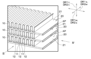
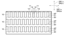
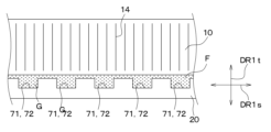
- FIG. 2 is an enlarged view of part II in FIG. 1.
- FIG. 3 is a side view of the tube and the first fin as seen from the direction of the arrow indicated by III in FIG. 2;
- FIG. 3 is a side view of the tube and the first fin viewed from the direction of the arrow indicated by IV in FIG. 2;
- FIG. 2 is an enlarged view of portion V in FIG. 1.
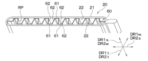
- FIG. 3 is a sectional view of the tube concerning a 1st embodiment.
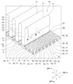
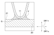
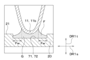
- FIG. 3 is a diagram for explaining a method of joining a first fin and a tube according to the first embodiment. 8 is a sectional view of a portion VIII in FIG. 7.
- FIG. 3 is a diagram for explaining a method of joining a first fin and a tube according to the first embodiment.
- 8 is a sectional view of a portion VIII in FIG. 7.
- FIG. 8 is a cross-sectional view of the IX portion in FIG. 7.
- FIG. FIG. 8 is a side view of the first fin and tube viewed from the direction of the arrow indicated by X in FIG. 7; It is a figure which shows the guide groove based on the 1st modification of 1st Embodiment. It is a figure which shows the guide groove based on the 2nd modification of 1st Embodiment. It is a figure which shows the guide groove based on the 3rd modification of 1st Embodiment.
- FIG. 14 is a cross-sectional view of a portion XIV in FIG. 13;
- FIG. 9 is a diagram corresponding to FIG. 9 in the second embodiment.
- FIG. 9 is a diagram corresponding to FIG. 9 in the third embodiment.
- FIG. 9 is a diagram corresponding to FIG. 9 in the fifth embodiment.
- FIG. FIG. 11 is a diagram corresponding to FIG. 10 in the sixth embodiment.
- FIG. 7 is a perspective view of a heat exchanger according to another embodiment.
- 21 is a cross-sectional view of the XXI portion in FIG. 20.
- FIG. 22 is an enlarged view of portion XXII in FIG. 21.
- FIG. 9 is a diagram corresponding to FIG. 8 of another embodiment.
- the heat exchanger 1 of this embodiment is used, for example, as an evaporator that constitutes a part of a refrigeration cycle that performs air conditioning in a vehicle interior.
- the evaporator exchanges heat between the refrigerant circulating in the refrigeration cycle and the air passing through the heat exchanger 1, and cools the air using the latent heat of evaporation of the refrigerant.
- the heat exchanger 1 includes a plurality of first fins 10, a plurality of tubes 20, a first header tank 31, a second header tank 32, a third header tank 33, a fourth header tank 34, an outer It includes a frame member 40 and the like.
- These members are made of a member (for example, metal such as aluminum) that has higher thermal conductivity than the adhesive G used to join the tube 20 and the first fin 10, which will be described later.
- these members are not limited to aluminum, and may be formed of a metal different from aluminum, or may be formed of a member different from metal, for example, a resin having high conductivity.
- the plurality of tubes 20 are stacked and arranged at predetermined intervals in a direction crossing the air flow direction. That is, the heat exchanger 1 of this embodiment is a stacked heat exchanger in which a plurality of tubes 20 are arranged in a stacked manner, and is a fin-tube heat exchanger.
- the plurality of tubes 20 are arranged in two rows, one on the upstream side and the other on the downstream side in the air flow direction.
- Each of the plurality of tubes 20 extends linearly from one end to the other end.
- One end of the plurality of tubes 20 is inserted into the first header tank 31 or the second header tank 32, and the other end is inserted into the third header tank 33 or the fourth header tank 34.
- the first header tank 31 and the second header tank 32 distribute refrigerant to the plurality of tubes 20. Further, the third header tank 33 and the fourth header tank 34 collect the refrigerant flowing from the plurality of tubes 20. Note that the tubes 20 are not limited to having two rows in the air flow direction, but may have a structure in which they have only one row in the air flow direction.
- air passages are formed between the plurality of tubes 20 and between the tubes 20 adjacent to each other in the stacking direction.
- An AP is formed.
- the first fin 10 is provided in the air passage AP.
- the first fin 10 is joined to a flat surface of the tube 20. That is, the first fin 10 of this embodiment is an outer fin provided on the outside of the tube 20.
- the surface of the tube 20 will also be referred to as the outer circumferential surface 21.
- a guide groove 70 (described later) is formed in the outer circumferential surface 21 of the tube 20 to guide the adhesive G to a portion where the tube 20 and the first fin 10 are joined.
- the tube 20 has a flat cylindrical cross-sectional shape.
- the tube 20 is formed by bending a single metal plate into a tubular shape, and then joining some surfaces of the metal plates by overlapping each other.
- a refrigerant passage RP is formed inside the tube 20 as a flow path portion through which a refrigerant, which is a fluid, flows.
- the tube 20 has a second fin 60 in its refrigerant passage RP. Specifically, the second fin 60 is joined to the flat inner surface of the tube 20. That is, the second fin 60 of this embodiment is an inner fin provided inside the tube 20.
- the inner surface of the tube 20 will also be referred to as the inner peripheral surface 22.
- a groove (not shown) is formed in the inner peripheral surface 22 of the tube 20 to guide the adhesive G to a portion where the tube 20 and the second fin 60 are joined.
- the tube 20 functions as a flow path forming section that forms an air passage AP and a refrigerant passage RP, which are flow path sections.
- the first fin 10 increases the heat exchange efficiency between the refrigerant and air by increasing the heat transfer area between the refrigerant flowing inside the tube 20 and the air flowing outside the tube 20.
- the first fin 10 is a so-called corrugated fin formed by bending a thin metal plate-like member made of aluminum or the like into a wave shape.
- the first fin 10 has a plurality of first tip portions 11 and a first extension portion 12 .
- the plurality of first tip portions 11 are portions in which a plate-like member constituting the first fin 10 is bent at predetermined intervals.
- the first tip portion 11 has an arc-shaped cross section perpendicular to the air flow direction, and is curved so as to swell toward the tube 20 .
- the first extending portion 12 is a portion disposed between the first tip portions 11 adjacent to each other among the plurality of first tip portions 11 .
- the first extending portion 12 is formed to extend in a planar manner so as to connect the first tip portions 11 adjacent to each other.
- the first extending portion 12 is provided with a plurality of louvers 14, each of which is a part of a plate-like member cut and raised.
- the first tip portions 11 are in contact with the outer circumferential surfaces 21 of the tubes 20 adjacent to each other, and their contact portions are bonded together with an adhesive G. That is, the outer circumferential surface 21 is a joint surface to which the first tip portion 11 is joined.
- the first fin 10 is fixed to the tube 20 by this joining structure. Details of the method for joining the first fin 10 and tube 20 will be described later.
- the thickness direction of the first fin 10 is referred to as the first fin thickness direction DR1t, and the direction in which the wave-shaped fin extends is referred to as the first fin stretching direction DR1s.
- a direction perpendicular to the first fin plate thickness direction DR1t and the first fin stretching direction DR1s is defined as a first fin width direction DR1w.
- the first fin thickness direction DR1t is a direction in which waves in the wave-shaped first fin 10 reciprocate, and corresponds to the fin thickness direction.
- the first fin stretching direction DR1s is a direction in which the plurality of first tip portions 11 and the plurality of first stretching portions 12 are arranged alternately, and corresponds to the fin stretching direction.
- the first fin width direction DR1w corresponds to the fin width direction.
- the first fin 10 is arranged such that the first fin plate thickness direction DR1t is the stacking direction of the tube 20, and the first fin stretching direction DR1s is the longitudinal direction of the tube 20. Further, the first fin 10 is arranged such that the first fin width direction DR1w is the air flow direction in the air passage AP.
- the first fin extension direction DR1s corresponds to the direction extending in the longitudinal direction of the outer circumferential surface 21 of the tube 20. Further, the first fin width direction DR1w coincides with the width direction of the tube 20.
- the second fin 60 is a so-called corrugated fin formed by bending a thin metal plate-like member made of aluminum or the like into a wave shape.
- the second fin 60 has a plurality of second tip portions 61 and a plurality of second extension portions 62.
- the plurality of second tip portions 61 are portions obtained by bending a plate-like member constituting the second fin 60 at predetermined intervals.
- the second tip 61 has an arcuate cross-section perpendicular to the refrigerant flow direction, and is curved so as to swell toward the inner circumferential surface 22 of the tube 20 .
- the second extending portion 62 is a portion disposed between two adjacent second tip portions 61 among the plurality of second tip portions 61 .
- the second extending portion 62 is formed to extend in a planar manner so as to connect the second tip portions 61 that are adjacent to each other.
- the second tip 61 of the second fin 60 contacts the inner circumferential surface 22 of the tube 20, and the contact portions are joined by adhesive G. That is, the inner circumferential surface 22 is a joint surface to which the second tip portion 61 is joined.
- the second fin 60 is fixed to the tube 20 by this joining structure.
- the method of joining the second fin 60 and the tube 20 is the same as the method of joining the first fin 10 and the tube 20, so the details of the joining method will be described in the method of joining the first fin 10 and the tube 20 described later. do.
- the thickness direction of the second fin 60 is referred to as a second fin thickness direction DR2t, and the direction in which the wave-shaped fin extends is referred to as a second fin extension direction DR2s. Further, the direction perpendicular to the second fin plate thickness direction DR2t and the second fin stretching direction DR2s is defined as the second fin width direction DR2w.
- the second fin thickness direction DR2t is a direction in which waves in the wave-shaped second fin 60 reciprocate, and corresponds to the fin thickness direction.
- the second fin stretching direction DR2s is a direction in which the plurality of second tip portions 61 and the plurality of second stretching portions 62 are arranged alternately, and corresponds to the fin stretching direction.
- the second fin width direction DR2w corresponds to the fin width direction.
- the second fin 60 is arranged so that the second fin thickness direction DR2t is the stacking direction of the tubes 20 and coincides with the first fin thickness direction DR1t. Further, the second fin 60 is arranged so that the second fin stretching direction DR2s is the width direction of the tube 20 and coincides with the first fin width direction DR1w. The second fins 60 are arranged so that the second fin width direction DR2w is the refrigerant flow direction in the refrigerant passage RP and coincides with the first fin extension direction DR1s.
- An outer frame member 40 is provided on the outside in the direction in which the plurality of tubes 20 and the plurality of first fins 10 are arranged alternately.
- a piping connection member (not shown) having a refrigerant inlet for supplying refrigerant and a refrigerant outlet for discharging the refrigerant is fixed to the outer frame member 40.
- the refrigerant that flows into the first header tank 31 from the refrigerant inlet of the piping connection member flows through the first header tank 31 to the fourth header tank 34 and the plurality of tubes 20 in a predetermined path, and then flows from the refrigerant outlet of the piping connection member. leak.
- the air flowing through the air passage AP provided with the first fin 10 is cooled by the latent heat of evaporation of the refrigerant flowing through the first to fourth header tanks 31 to 34 and the plurality of tubes 20.
- the first fins 10 are bonded together by an adhesive G placed at a portion of the outer circumferential surface 21 of the tube 20 where the first fins 10 are placed.
- the first fin 10 is fixed to the first fin plate thickness by the adhesive G disposed on the outer circumferential surface 21 of the tube 20 disposed on one side of the first fin plate thickness direction DR1t of the first fin 10.
- the first tip 11 on one side in the direction DRlt is joined to the tube 20.
- first fin 10 is attached in the first fin thickness direction DR1t by the adhesive G disposed on the outer peripheral surface 21 of the tube 20 disposed on the other side of the first fin thickness direction DR1t of the first fin 10.
- the first tip 11 on the other side of the tube 20 is joined to the tube 20 .
- the method of joining the tube 20 to one side of the first fin 10 in the first fin thickness direction DR1t is the same as the method of joining the tube 20 to the other side of the first fin 10 in the first fin thickness direction DR1t. . Therefore, in this embodiment, only the details of the method of joining the tube 20 to one side of the first fin 10 in the first fin thickness direction DR1t will be described, and the first fin thickness direction DR1t of the first fin 10 will be described in detail. Details of the method of joining the other side and the tube 20 will be omitted.
- an adhesive G for joining the first fin 10 is placed in the guide groove 70 formed on the outer peripheral surface 21 of the tube 20.
- the depth of the guide groove 70 is, for example, 1 mm. However, the depth of the guide groove 70 is not limited, and the depth of the guide groove 70 may be larger than 1 mm or smaller than 1 mm.
- the first fin 10 and the tube 20 are joined by placing the first tip 11 of the first fin 10 on the outer peripheral surface 21 of the tube 20 with the adhesive G placed in the guide groove 70. Ru.
- a filler is mixed into a resin member having adhesive properties in order to increase thermal conductivity.
- FIG. 7 only a part of the first fin 10 is illustrated, and illustration of other parts is omitted. Further, in FIGS. 7 to 10, the adhesive G is hatched in a dot pattern to make it easier to understand.
- a plurality of guide grooves 70 of this embodiment are formed on the outer circumferential surface 21 of the tube 20, as shown in FIG.
- the guide groove 70 is formed linearly along the outer peripheral surface 21. Further, the guide groove 70 extends obliquely in the first fin extension direction DR1s and the first fin width direction DR1w.
- the guide groove 70 includes a first guide groove 71 that extends obliquely in the first fin extension direction DR1s and the first fin width direction DR1w.
- the guide groove 70 also includes a second guide groove 72 that extends obliquely in the first fin extension direction DR1s and the first fin width direction DR1w, and that extends across the direction in which the first guide groove 71 extends.
- a plurality of first guide grooves 71 are formed so as to be lined up along the first fin extension direction DR1s. Further, the first guide groove 71 has a rectangular cross-sectional shape on a surface perpendicular to the direction in which the first guide groove 71 extends. The first guide groove 71 is formed across one or more first fins 10.
- a plurality of second guide grooves 72 are formed so as to be lined up along the first fin width direction DR1w.
- the second guide groove 72 has a rectangular cross-sectional shape on a surface perpendicular to the direction in which the second guide groove 72 extends.
- the second guide groove 72 is formed across one or more first fins 10.
- the cross-sectional shape of the first guide groove 71 and the second guide groove 72 on a surface perpendicular to the direction in which they extend is not limited to a rectangular shape, and may be, for example, an arc shape or a V-shape. Good too.
- the first guide groove 71 and the second guide groove 72 are formed over the entire outer peripheral surface 21 of the tube 20 and intersect with each other. That is, the first guide groove 71 and the second guide groove 72 are formed in a lattice shape.
- the first tip portion 11 of the first fin 10 is joined to a portion where the first guide groove 71 and the second guide groove 72 intersect with each other.
- the first guide groove 71 and the second guide groove 72 are formed to intersect with each other at a portion of the outer peripheral surface 21 of the tube 20 where the first tip portion 11 is arranged.
- the portion of the outer circumferential surface 21 of the tube 20 where the first fin 10 is arranged is a portion where the first guide groove 71 and the second guide groove 72 intersect, and a portion where the first guide groove 71 and the second guide groove 72 intersect.
- the portions that are not formed are arranged alternately along the first fin width direction DR1w.
- the cross section shown in FIG. 8 shows a cross section of a portion that is perpendicular to the first fin width direction DR1w and where the first guide groove 71 and the second guide groove 72 intersect.
- the cross section shown in FIG. 9 shows a cross section of a portion that is perpendicular to the first fin width direction DR1w and in which the first guide groove 71 and the second guide groove 72 are not formed.
- the adhesive G for joining the first fin 10 to the tube 20 is filled into the first guide groove 71 and the second guide groove 72 formed in this way when joining the first fin 10 and the tube 20. let When the adhesive G is filled into the first guide groove 71 and the second guide groove 72, it flows into the first guide groove 71 and the second guide groove 72 so as to spread inside the first guide groove 71 and the second guide groove 72. Further, the adhesive G is guided and filled along the first guide groove 71 and the second guide groove 72 by the surface tension generated on its own surface. Therefore, the adhesive G guided and filled into the first guide groove 71 and the second guide groove 72 is arranged so that the size of the grooves in the depth direction is substantially uniform.
- the adhesive G guided and arranged in the first guide groove 71 and the second guide groove 72 is arranged so that the film thickness is substantially constant.
- the entire space formed by the first guide groove 71 and the second guide groove 72 is filled with the adhesive G.
- the first fin 10 is joined to the outer peripheral surface 21 of the tube 20 by the adhesive G disposed in the first guide groove 71 and the second guide groove 72 in this way.
- the part facing the part where the first guide groove 71 and the second guide groove 72 are formed is coated with the adhesive G.
- the outer circumferential surface 21 of the tube 20 is contacted through the tube 20 .
- the first tip portion 11 of the first fin 10 faces a portion where the first guide groove 71 and the second guide groove 72 are not formed among the portions that face the outer circumferential surface 21 of the tube 20.
- the portion directly contacts the outer circumferential surface 21 of the tube 20 without using the adhesive G.
- a portion of the first fin 10 directly contacts the tube 20 without using the adhesive G.
- the part of the first tip 11 that directly contacts the tube 20 will be referred to as the direct contact part 11a, and the part that does not directly contact the tube 20 but indirectly contacts the tube 20 via the adhesive G. is also called indirect contact portion 11b.
- a fillet F is formed with adhesive G at the joint between the first fin 10 and the tube 20, as shown in FIGS. 8 to 10.
- the fillet F is formed on one side and the other side of the first tip portion 11 in the first fin extension direction DR1s.
- the fillet F is formed on one side and the other side of the direct contact portion 11a and the indirect contact portion 11b in the first fin extension direction DR1s.
- This fillet F is formed by the adhesive G being sucked up toward the first tip 11 by capillary force generated when the first fin 10 is joined to the outer peripheral surface 21 of the tube 20. Therefore, the size of the fillet F in the first fin plate thickness direction DR1t decreases as it moves away from the first tip 11 like the foot of a mountain.
- the fillet F formed on one side of the indirect contact portion 11b in the first fin extending direction DR1s and the other side in the first fin extending direction DR1s is formed in the first guide groove 71 and the second guide groove 72, as shown in FIG. They are connected via the filled adhesive G. Therefore, the fillet F formed on one side of the indirect contact portion 11b in the first fin stretching direction DR1s and the fillet F formed on the other side of the first fin stretching direction DR1s have substantially equal surface tensions. Therefore, the fillet F formed on one side of the indirect contact portion 11b in the first fin stretching direction DR1s and the fillet F formed on the other side of the first fin stretching direction DR1s are large in the first fin plate thickness direction DR1t. are approximately equal.
- the size of the fillet F in the first fin plate thickness direction DR1t will also be referred to as fillet height Fh.
- the fillet F formed on one side of the indirect contact portion 11b in the first fin stretching direction DR1s extends to the end of the first guide groove 71 and the second guide groove 72 on one side in the first fin stretching direction DR1s. It is formed by The fillet F formed on the other side of the indirect contact portion 11b in the first fin stretching direction DR1s is formed to extend to the end of the first guide groove 71 and the second guide groove 72 on the other side in the first fin stretching direction DR1s. be done.
- the size in the first fin width direction DR1w of the fillet F formed on one side and the other side of the indirect contact portion 11b in the first fin extension direction DR1s is the same as that of the first guide groove 71 and the second guide groove 72. It can be set depending on the size of the first fin stretching direction DR1s.
- the size of the first guide groove 71 and the second guide groove 72 in the first fin extending direction DR1s of the present embodiment is a size that can sufficiently secure the bonding force when the first fin 10 and the tube 20 are bonded. It is formed of.
- the size of the fillet F in the first fin stretching direction DR1s will also be referred to as the fillet width Fw.
- the fillets F formed on one side of the direct contact portion 11a in the first fin stretching direction DR1s and on the other side of the first fin stretching direction DR1s are not directly continuous as shown in FIG. However, as shown in FIG. 10, the fillet F formed on the other side of the direct contact portion 11a in the first fin stretching direction DR1s is the fillet F formed on the other side of the indirect contact portion 11b in the first fin stretching direction DR1s. It is connected to F. Although not shown, the fillet F formed on one side of the direct contact portion 11a in the first fin stretching direction DR1s is continuous with the fillet F formed on one side of the indirect contact portion 11b in the first fin stretching direction DR1s. ing.
- the fillet F formed on one side of the direct contact portion 11a in the first fin stretching direction DR1s and the fillet F formed on the other side of the first fin stretching direction DR1s are connected to the first guide groove 71 and the second guide groove 71. They are connected via the adhesive G placed in the groove 72.
- the fillet F formed on one side of the direct contact portion 11a in the first fin stretching direction DR1s and the fillet F formed on the other side of the first fin stretching direction DR1s have substantially equal surface tensions. Therefore, the fillet F formed on one side of the direct contact portion 11a in the first fin stretching direction DR1s and the fillet F formed on the other side of the first fin stretching direction DR1s have substantially equal fillet heights Fh. Become. Further, the fillet F formed on one side of the direct contact portion 11a in the first fin stretching direction DR1s has a fillet width Fw approximately equal to that of the fillet F formed on one side of the indirect contact portion 11b in the first fin stretching direction DR1s. be equal.
- the fillet F formed on the other side of the direct contact portion 11a in the first fin stretching direction DR1s has a fillet width Fw approximately equal to that of the fillet F formed on the other side of the indirect contact portion 11b in the first fin stretching direction DR1s. be equal.
- the fillets F formed on one side and the other side of the direct contact portion 11a in the first fin stretching direction DR1s also depend on the size of the first guide groove 71 and the second guide groove 72 in the first fin stretching direction DR1s. Can be set.
- the fillet F formed between the first tip 11 of the first fin 10 and the outer peripheral surface 21 of the tube 20 joins the first fin 10 and the tube 20 more firmly.
- the second fin 60 and tube 20 are joined by a joining method similar to the joining method of the first fin 10 and tube 20. That is, the second fin 60 is fixed in the second fin thickness direction by the adhesive G disposed on the inner peripheral surface 22 of the tube 20 disposed on one side of the second fin thickness direction DR2t of the second fin 60. A second tip 61 on one side of the DR 2t is joined to the inner circumferential surface 22 of the tube 20. Further, the second fin 60 is attached in the second fin thickness direction by the adhesive G disposed on the inner peripheral surface 22 of the tube 20 disposed on the other side of the second fin thickness direction DR2t of the second fin 60. The second tip 61 on the other side of the DR 2t is joined to the inner circumferential surface 22 of the tube 20.
- a groove (not shown) for filling the adhesive G is formed in the inner circumferential surface 22 of the tube 20, and the groove is filled with the adhesive G for joining the second fin 60.
- This groove is formed in a lattice shape, similar to the first guide groove 71 and the second guide groove 72 formed on the outer circumferential surface 21 of the tube 20. That is, the groove formed in the inner circumferential surface 22 has a first groove that extends obliquely in the second fin extension direction DR2s and the second fin width direction DR2w. Further, the groove formed in the inner circumferential surface 22 has a second groove that is inclined in the second fin extension direction DR2s and the second fin width direction DR2w, and extends across the direction in which the first groove extends.
- the second fin 60 is joined to the inner circumferential surface 22 of the tube 20 by the adhesive G filled in the first groove and second groove formed in this way.
- the second tip 61 of the second fin 60 has a portion that faces the inner circumferential surface 22 of the tube 20, and a portion that faces the portion where the first groove and the second groove are formed is attached to the tube through the adhesive G. Contact 20.
- the second tip 61 of the second fin 60 among the parts facing the inner circumferential surface 22 of the tube 20, the part facing the part where the first groove and the second groove are not formed is bonded. It directly contacts the inner circumferential surface 22 of the tube 20 without using the agent G. In other words, a portion of the second tip 61 directly contacts the tube 20 without using the adhesive G.
- fillets F are formed on one side and the other side of the second tip portion 61 in the second fin extension direction DR2s.
- the thermal conductivity of the adhesive resin member included in the adhesive G is about 1/100 to 1/1000 lower than that of the first fin 10 and the second fin 60 formed of metal. Therefore, the method of bonding the first fin 10 and the second fin 60 to the tube 20 using the adhesive G is based on heat conduction when the first fin 10 and the second fin 60 and the tube 20 exchange heat. This causes a decline in sexual performance.
- the decrease in thermal conductivity between the first fin 10 and the second fin 60 and the tube 20 is caused by the heat exchanger 1 exchanging heat between the refrigerant circulating in the refrigeration cycle and the air passing through the heat exchanger 1. This is a factor that reduces the heat exchange efficiency.
- first fin 10 of this embodiment a part of the first tip 11 is in direct contact with the outer circumferential surface 21 of the tube 20 without using the adhesive G. Therefore, a decrease in thermal conductivity between the first fins 10 and the tube 20 that occurs when they are bonded using the adhesive G can be suppressed.
- a part of the second tip 61 of the second fin 60 is in direct contact with the inner circumferential surface 22 of the tube 20 without using the adhesive G. Therefore, a decrease in thermal conductivity between the second fins 60 and the tube 20 that occurs when they are bonded using the adhesive G can be suppressed. Therefore, the heat exchange efficiency of the heat exchanger 1 can be improved.
- a portion of the first tip portion 11 of the first fin 10 is in direct contact with the outer circumferential surface 21 of the tube 20 without using the adhesive G. Furthermore, a portion of the second tip 61 of the second fin 60 is in direct contact with the inner circumferential surface 22 of the tube 20 without using the adhesive G. For this reason, the amount of the adhesive G is suppressed compared to a configuration in which the adhesive G is provided so that all of the first tip portion 11 and the second tip portion 61 are in contact with the tube 20 via the adhesive G. be able to.
- the adhesive G of this embodiment includes a filler in order to improve thermal conductivity. However, when a filler is mixed into the adhesive G, the adhesiveness of the adhesive G is reduced.
- the heat exchanger 1 of the present embodiment is configured so that a portion of the first fin 10 and the second fin 60 directly contact the tube 20 without using the adhesive G as described above. , the heat exchange efficiency of the heat exchanger 1 can be improved. Therefore, even if the filler content is reduced compared to a case without such a configuration, the adhesiveness between the first fin 10 and the second fin 60 and the tube 20 can be improved while ensuring heat exchange efficiency. can be ensured.
- the tube 20 has the outer circumferential surface 21 to which the first tip 11 is joined.
- the outer circumferential surface 21 extends in a planar manner, and is formed with a first guide groove 71 and a second guide groove 72 that guide the adhesive G to a portion where the tube 20 and the first fin 10 are joined.
- the first guide groove 71 and the second guide groove 72 guide the adhesive G around the portion of the first tip portion 11 that directly contacts the tube 20 .
- the adhesive G when disposing the adhesive G on the outer peripheral surface 21 of the tube 20, the adhesive G is guided to the first guide groove 71 and the second guide groove 72. Therefore, it is possible to easily arrange the adhesive G around the first tip portion 11, so that the outer circumferential surface 21 of the tube 20 and the first fin 10 can be reliably joined.
- a fillet F is formed at the joint portion of the tube 20 and the first fin 10.
- the fillet height Fh of the fillet F decreases as it moves away from the first tip 11 like the foot of a mountain, and is formed up to the ends of the first guide groove 71 and the second guide groove 72.
- the fillet width Fw the lower the joinability between the tube 20 and the first fin 10.
- the fillet width Fw of the fillet F is set depending on the size of the first guide groove 71 and the second guide groove 72 in the first fin extending direction DR1s.
- the size of the first guide groove 71 and the second guide groove 72 in the first fin extending direction DR1s is formed to a size that can sufficiently secure the bonding force when the first fin 10 and the tube 20 are bonded. ing. Therefore, the tube 20 and the first fin 10 can be reliably joined.
- the first guide groove 71 extends obliquely with respect to the first fin extension direction DR1s.
- the first fin 10 when joining the tube 20 and the first fin 10, even if the positions of the tube 20 and the first fin 10 deviate from the designed position in the first fin extension direction DR1s, the first fin 10 can be reliably brought into direct contact with the tube 20. That is, compared to the case where the first guide groove 71 and the second guide groove 72 are formed only in the portion facing the first tip portion 11, the first guide groove 71 and the second guide groove 72 can be easily formed without requiring high design accuracy.
- the groove 71 and the second guide groove 72 can be formed in the outer peripheral surface 21 of the tube 20.
- the outer circumferential surface 21 includes a first guide groove 71 extending obliquely with respect to the first fin width direction DR1w and a first guide groove 71 extending obliquely with respect to the first fin width direction DR1w.
- a second guide groove 72 is formed that extends across the direction in which the groove 71 extends.
- the tube 20 and the first fin 10 can be joined by the adhesive G filled in the first guide groove 71 and the second guide groove 72. Therefore, the range in which the tube 20 and the first fin 10 come into contact with the adhesive G is increased compared to the case where only one of the first guide groove 71 and the second guide groove 72 is formed on the outer peripheral surface 21. can do. Therefore, the tube 20 and the first fin 10 can be reliably joined.
- the guide groove 70 includes the first guide groove 71 that extends obliquely in the first fin extension direction DR1s and the first fin width direction DR1w.
- the guide groove 70 also includes a second guide groove 72 that extends obliquely in the first fin extension direction DR1s and the first fin width direction DR1w, and that extends across the direction in which the first guide groove 71 extends.
- the guide groove 70 is not limited to this configuration.
- the guide groove 70 may have a configuration in which only one of the first guide groove 71 and the second guide groove 72 extends obliquely in the first fin extension direction DR1s and the first fin width direction DR1w.
- the first guide groove 71 may be eliminated compared to the first embodiment, and the configuration may include only the second guide groove 72.
- the second guide groove 72 may be omitted compared to the first embodiment, and the second guide groove 72 may be configured to include only the first guide groove 71.
- the guide groove 70 includes the first guide groove 71 that extends obliquely in the first fin extension direction DR1s and the first fin width direction DR1w.
- the guide groove 70 also includes a second guide groove 72 that extends obliquely in the first fin extension direction DR1s and the first fin width direction DR1w, and that extends across the direction in which the first guide groove 71 extends.
- the guide groove 70 is not limited to this configuration.
- the guide groove 70 may include a third guide groove 73 extending along the first fin extension direction DR1s as shown in FIG. 12.
- the guide groove 70 includes the first guide groove 71 that extends obliquely in the first fin extension direction DR1s and the first fin width direction DR1w.
- the guide groove 70 also includes a second guide groove 72 that extends obliquely in the first fin extension direction DR1s and the first fin width direction DR1w, and that extends across the direction in which the first guide groove 71 extends.
- the guide groove 70 is not limited to this configuration.
- the guide groove 70 may include a fourth guide groove 74 and a fifth guide groove 75 extending along the first fin width direction DR1w, as shown in FIGS. 13 and 14.
- the fourth guide groove 74 is formed on one side of the outer circumferential surface 21 of the tube 20 in the first fin extension direction DR1s at a portion facing the first tip portion 11.
- the fifth guide groove 75 is formed on the other side of the outer circumferential surface 21 of the tube 20 in the first fin extension direction DR1s at a portion facing the first tip portion 11.
- the tip of the first fin 10 can be brought into direct contact with the tube 20. Therefore, compared to a configuration in which only a portion of the tip of the first fin 10 directly contacts the tube 20, a decrease in thermal conductivity that occurs when bonding with the adhesive G is suppressed, and the heat exchanger 1 Heat exchange efficiency can be improved.
- first guide groove 71 and the second guide groove 72 may be configured to straddle only one first fin 10.
- first guide groove 71 and the second guide groove 72 may be formed at each portion of the outer circumferential surface 21 of the tube 20 that faces each of the plurality of first distal end portions 11 .
- the first guide groove 71 and the second guide groove 72 are formed so as to intersect with each other at a portion of the outer circumferential surface 21 of the tube 20 where the first tip portion 11 is arranged.
- the invention is not limited thereto.
- first guide groove 71 and the second guide groove 72 may be formed to intersect with each other at a portion of the outer circumferential surface 21 of the tube 20 where the first tip portion 11 is not arranged.
- adhesive G is slightly interposed between the first fins 10 and the tubes 20. That is, the first tip portion 11 of this embodiment does not entirely contact the outer circumferential surface 21 directly, and does not include the direct contact portion 11a of the first embodiment. A portion of the first tip 11 of the first fin 10 is in contact with the tube 20 via a thin film adhesive G.
- the adhesive G disposed between the first fin 10 and the tube 20 has a gradient in which the size in the first fin plate thickness direction DR1t gradually decreases toward the tip of the first fin 10.
- the thin film adhesive G is a portion of the adhesive G disposed between the first fin 10 and the tube 20 where the size in the first fin plate thickness direction DR1t is smallest.
- the thin film adhesive G has the smallest distance between the first fin 10 and the outer peripheral surface 21 of the tube 20 among the adhesives G disposed between the first fin 10 and the tube 20. It is a part provided in the body part.
- the portion where the thin film adhesive G is formed is shown with a dotted line.
- the reason why the thin film adhesive G is interposed between the first fin 10 and the tube 20 will be explained.
- the first fin 10 and the tube 20 are bonded together by an adhesive G placed in the first guide groove 71 and the second guide groove 72.
- the adhesive G disposed in the first guide groove 71 and the second guide groove 72 is sucked up toward the first tip portion 11 by capillary force. Therefore, when the first fins 10 and the tube 20 are joined together, a slight amount of adhesive G may be present between the first fins 10 and the tube 20.
- a thin film of adhesive G is provided between the first tip portion 11 and the outer circumferential surface 21.
- the thickness of the thin film adhesive G formed in this way is very small compared to the thickness of the fillet F.
- the film thickness of the thin film adhesive G is determined by the size of the first guide groove 71 and the second guide groove 72 in the first fin plate thickness direction DR1t (that is, the size of the first guide groove 71 and the second guide groove 72). (size in depth direction) is smaller.
- the thickness of the thin film adhesive G may be 1/5 or less, or 1/10 or less of the size of the first guide groove 71 and the second guide groove 72 in the first fin plate thickness direction DR1t. There may be.
- the thickness of the thin film adhesive G of this embodiment is 50 ⁇ m or less.
- the film thickness of the adhesive G may be greater than 50 ⁇ m, such as 100 ⁇ m, for example.
- the heat exchanger 1 loses heat compared to the configuration of the first embodiment. Exchange efficiency can be improved to the same extent.
- the thin film adhesive G provided between the first tip 11 and the outer peripheral surface 21 is guided and arranged along the tip of the first tip 11. Therefore, the thin film adhesive G provided between the first tip portion 11 and the outer circumferential surface 21 is formed to have a substantially constant film thickness. Therefore, variations in thermal conductivity between the first fin 10 and the tube 20 due to variations in the thickness of the thin film adhesive G can be suppressed.
- a thin film adhesive G is formed between the first fin 10 and the tube 20
- a thin film adhesive G is formed between the second fin 60 and the tube 20. G may be formed.
- the heat exchange efficiency of the heat exchanger 1 can be maintained at the same level as the configuration of the first embodiment. It can be improved to a certain extent.
- the first distal end portion 11 of this embodiment has one protrusion portion 11c that protrudes toward the tube 20 at the distal end of the first distal end portion 11.
- the protruding portion 11c is formed so that the portion closest to the tube 20 of the first tip portion 11 of the first fin 10 that is curved so as to swell toward the tube 20 further swells toward the tube 20. ing. Further, the protruding portion 11c extends along the first fin width direction DR1w at the tip of the first tip portion 11, and is formed in a semi-cylindrical shape.
- the protruding portion 11c has an arc-shaped cross section perpendicular to the air flow direction.
- the protruding portion 11c of this embodiment directly contacts the outer peripheral surface 21 of the tube 20 without using the adhesive G.
- portions of the protruding portion 11c in the first tip portion 11 on one side and the other side in the first fin extension direction DR1s contact the outer circumferential surface 21 of the tube 20 via the adhesive G.
- the shape of the cross section perpendicular to the air flow direction of the protruding portion 11c is not limited to an arc shape, and may be, for example, rectangular or triangular.
- the space between the first tip 11 and the tube 20 becomes larger compared to a configuration that does not have the protrusion 11c. Therefore, since the amount of adhesive G between the first tip portion 11 and the tube 20 can be increased, the first fin 10 can be reliably joined to the tube 20 using the adhesive G.
- the first tip 11 of the first fin 10 is provided with the protrusion 11c, but even if the second tip 61 of the second fin 60 is provided with the protrusion 11c. good. Even in this case, the second fin 60 can be reliably joined to the tube 20 with the adhesive G, as in the case where the first tip 11 is provided with the protrusion 11c.
- the protruding portion 11c extends along the first fin width direction DR1w at the tip of the first tip portion 11 and is formed in a semi-cylindrical shape.
- the protruding portions 11c may have a hemispherical shape and may be formed in plural along the first fin width direction DR1w.
- the first distal end portion 11 of this embodiment has one recessed portion 11d formed by recessing the distal end of the first distal end portion 11 on the side opposite to the outer circumferential surface 21 of the tube 20.
- the recessed portion 11d is curved such that the center portion of the first tip portion 11 of the first fin 10 in the first fin extension direction DR1s is recessed toward the center of the first fin 10 in the first fin plate thickness direction DR1t. It is formed.
- the recessed portion 11d is recessed on the side opposite to the side joined to the tube 20.
- the recessed portion 11d has an arcuate cross section perpendicular to the air flow direction.
- the recessed portion 11d is formed to penetrate along the first fin width direction DR1w.
- the first tip portion 11 having such a recessed portion 11d has a W-shaped cross section in the first fin width direction DR1w, that is, perpendicular to the air flow direction in the air passage AP.
- the first tip portion 11 has a shape in which one side and the other side of the recessed portion 11d in the first fin extension direction DR1s protrude toward the tube 20.
- the first distal end portion 11 is arranged so that the portions on one side and the other side in the first fin extending direction DR1s of the recessed portion 11d protruding toward the tube 20 are attached to the outer circumferential surface 20 of the tube 20 without using the adhesive G. come into direct contact with.
- adhesive G is placed in the space formed between the recess 11d and the tube 20. Thereby, the recessed portion 11d of the first tip portion 11 comes into contact with the outer circumferential surface 21 of the tube 20 via the adhesive G.
- the shape of the cross section perpendicular to the air flow direction of the recessed portion 11d is not limited to an arc shape, and may be, for example, rectangular or V-shaped.
- the first fin 10 including the first tip 11 having the recess 11d is joined to the tube 20 by the adhesive G placed in the recess 11d.
- the contact area between the first tip 11 and the adhesive G can be increased compared to a configuration that does not have the recess 11d. Therefore, the first fin 10 can be reliably joined to the tube 20 using the adhesive G.
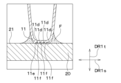
- the first fin 10 of this embodiment is formed by bending a plate-like member into a wave shape, and has a first tip portion 11, which is the tip of the plate-like member formed in the wave shape, as shown in FIG.
- the tube 20 has a straight portion 11e extending planarly along the outer circumferential surface 21 of the tube 20.
- the straight portion 11e is formed in a planar shape along the first fin extension direction DR1s and the first fin width direction DR1w.
- a plurality of recessed portions 11d are formed in the straight portion 11e on the side opposite to the outer circumferential surface 21 of the tube 20.
- Each of the plurality of recesses 11d is formed in a curved manner so as to be recessed toward the center of the first fin 10 in the first fin plate thickness direction DR1t.
- the first tip portion 11 having such a plurality of recesses 11d has a cross section perpendicular to the air flow direction having a plurality of unevenness.
- the first tip portion 11 has a cross section perpendicular to the air flow direction in which a plurality of recesses 11d and a plurality of convex portions 11f are arranged alternately along the first fin extension direction DR1s in a straight portion 11e.
- the convex portion 11f is a portion that protrudes toward the outer circumferential surface 21 of the tube 20 compared to the recessed portion 11d.
- the convex portion 11f that protrudes toward the tube 20 directly contacts the outer circumferential surface 21 of the tube 20 without using the adhesive G.
- the recess 11d contacts the outer circumferential surface 21 of the tube 20 via the adhesive G.
- the first fin 10 including the first tip 11 having the recess 11d is joined to the tube 20 by the adhesive G placed in the recess 11d.
- the first fin 10 can be reliably joined to the tube 20 using the adhesive G.
- the straight portion 11e of the first tip portion 11 of the first fin 10 is provided with a plurality of recesses 11d and a plurality of protrusions 11f.
- the straight part 11e may have a plurality of recesses 11d and a plurality of convex parts 11f. Even in this case, the second fin 60 can be reliably joined to the tube 20 with the adhesive G, as in the case where the first tip 11 is provided with the recess 11d.
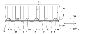
- a plurality of recesses 11d in this embodiment are formed along the first fin width direction DR1w.
- the recessed portion 11d is formed to penetrate the first tip portion 11 along the first fin extending direction DR1s, and has an arc-shaped cross section in the first fin extending direction DR1s.
- the first tip portion 11 having a plurality of recesses 11d in this manner has a shape in which a plurality of recesses 11d and a plurality of convex portions 11f are arranged alternately along the first fin width direction DR1w.
- the convex portion 11f is a portion that protrudes toward the outer circumferential surface 21 of the tube 20 compared to the recessed portion 11d.
- the convex portion 11f that protrudes toward the tube 20 directly contacts the outer circumferential surface 21 of the tube 20 without using the adhesive G.
- the recess 11d contacts the outer circumferential surface 21 of the tube 20 via the adhesive G.
- the first fin 10 including the first tip 11 having the recess 11d is joined to the tube 20 by the adhesive G placed in the recess 11d.
- the first fin 10 can be reliably joined to the tube 20 using the adhesive G.
- the second fin 60 has a plurality of recesses 11d in the second tip 61. Even in this case, the second fin 60 can be reliably joined to the tube 20 with the adhesive G, as in the case where the first tip 11 is provided with the recess 11d.
- the heat exchanger 1 is a fin-tube heat exchanger in which the tubes 20 of the stacked heat exchanger are arranged in a stacked manner, but the heat exchanger 1 is not limited thereto.
- the heat exchanger 1 may be a fin-plate heat exchanger in which a plurality of plates P are stacked and arranged among stacked heat exchangers, as shown in FIGS. 20 to 22. .
- the heat exchanger 1 is a fin-plate heat exchanger, in the gaps between the plurality of plates P, for example, refrigerant passages RP and cooling water flows WP through which cooling water as a fluid flows are formed alternately in the stacking direction. be done.
- Inner fins IF are provided between the plurality of plates P that are adjacent to each other in the stacking direction. This inner fin IF is bonded by adhesive G to a plate P placed on one side in the stacking direction and a plate P placed on the other side in the stacking direction. Note that when the heat exchanger 1 is a fin-plate type heat exchanger, the plate P functions as a flow path forming section that forms a flow path section.
- the method for joining the tube 20 and the first fin 10 described in each of the above embodiments can be used. Thereby, it is possible to suppress a decrease in thermal conductivity between the plate P and the inner fin IF that occurs when they are bonded with the adhesive G, and improve the heat exchange efficiency of the heat exchanger 1.
- the fins arranged in this heat exchanger 1 are, for example, made by bending a thin metal plate-like member made of aluminum or the like into a wave shape, and cutting and raising portions that are adjacent to each other in the air flow direction are offset. It may also be configured with offset fins.
- the adhesive G may fill a part of the space formed by the first guide groove 71 and the second guide groove 72.
- the heat exchanger 1, which is a fin-tube type heat exchanger has the second fins 60 inside the tubes 20, but the present invention is not limited to this.
- the heat exchanger 1, which is a fin-tube type heat exchanger may have a configuration in which the second fins 60 are not provided inside the tubes 20.
- the guide grooves 70 are formed on the outer circumferential surface 21 and the inner circumferential surface 22 of the tube 20, but the present invention is not limited thereto.
- a configuration may be adopted in which the guide grooves 70 are not formed on the outer circumferential surface 21 and inner circumferential surface 22 of the tube 20.
Landscapes
- Engineering & Computer Science (AREA)
- Physics & Mathematics (AREA)
- Thermal Sciences (AREA)
- Mechanical Engineering (AREA)
- General Engineering & Computer Science (AREA)
- Geometry (AREA)
- Heat-Exchange Devices With Radiators And Conduit Assemblies (AREA)
Abstract
積層型熱交換器は、流路部(AP、RP、WP)を形成する複数の流路形成部(20、P)と、流路形成部に接着剤(G)によって接合されるフィン(10、60、IF)と、を備る。フィンは、波形状に形成されており、流路形成部に接合される複数の先端部(11、61)および互いに隣り合う先端部を接続するように延びる延伸部(12、62)が交互に並んで形成されている。先端部の少なくとも一部が接着剤を介することなく流路形成部に直接接触している。または、先端部の少なくとも一部が薄膜状の接着剤を介して流路形成部に接触しており、流路形成部は、先端部が接合される接合面(21、22)を有する。接合面は、平面状に延びるとともに、流路形成部とフィンとが接合される部位に接着剤を導く誘導溝(70、71、72、73、74、75)を有する。誘導溝は、先端部における薄膜状の接着剤を介して流路形成部に接触する部位の周辺に接着剤を導く。
Description
本出願は、2022年3月18日に出願された日本特許出願番号2022-043849号に基づくもので、ここにその記載内容が参照により組み入れられる。
本開示は、積層型熱交換器に関する。
従来、互いに平行に配列された複数の板状フィンと、各フィンに設けられた挿通孔に挿通される冷媒管とを有するフィン・アンド・チューブ型熱交換器が知られている(例えば、特許文献1参照)。このフィン・アンド・チューブ型熱交換器において、冷媒管がフィンの挿通孔に挿入されて接着剤によってフィンと接合されている。そして、このフィン・アンド・チューブ型熱交換器は、複数のフィンの間に空気などの流体を流すことによって、冷媒管を流れる冷媒と空気との熱交換を行う。
ところで、熱交換器はできるだけ大きな伝熱性能が求められるところ、特許文献1には、接着剤を用いることで低下する伝熱性能を補うための冷媒管とフィンとの接合方法が記載されている。具体的には、表面の略半周に接着剤が塗布された状態の冷媒管を挿通孔に挿入して接合させることによって、冷媒管の表面とフィンの挿通孔の内面とが直接接触する部分を設けて熱交換器の伝熱性能を向上させる接合方法が記載されている。また、冷媒管の表面に接着剤塗布用の溝を複数設け、溝内に充填した接着材によって冷媒管とフィンとを接合させるとともに、冷媒管における溝以外の表面と挿入孔内面とを直接接触させることで熱交換器の伝熱性能を向上させる接合方法が記載されている。
ところで、熱交換器はできるだけ大きな伝熱性能が求められるところ、特許文献1には、接着剤を用いることで低下する伝熱性能を補うための冷媒管とフィンとの接合方法が記載されている。具体的には、表面の略半周に接着剤が塗布された状態の冷媒管を挿通孔に挿入して接合させることによって、冷媒管の表面とフィンの挿通孔の内面とが直接接触する部分を設けて熱交換器の伝熱性能を向上させる接合方法が記載されている。また、冷媒管の表面に接着剤塗布用の溝を複数設け、溝内に充填した接着材によって冷媒管とフィンとを接合させるとともに、冷媒管における溝以外の表面と挿入孔内面とを直接接触させることで熱交換器の伝熱性能を向上させる接合方法が記載されている。
フィンを用いた熱交換器には、フィン・アンド・チューブ型熱交換器以外の構成の熱交換器として、例えば、偏平形状の板状のプレートと、薄板部材を波形状に往復させて折り曲げたフィンとを交互に複数積層された積層型熱交換器がある。積層型熱交換器では、複数のプレートのうち、互いに隣り合うプレートによって流体が流れる流路部が形成されるため、当該プレートが流路形成部として機能する。
また、積層型熱交換器では、当該流路部に波形状のフィンが設けられるとともに、フィンの板厚方向の一方側および他方側それぞれが流路形成部に接合される。このため、積層型熱交換器の伝熱性能を示す熱交換効率を確保するため、波形状のフィンと、流体が流れる流路部を形成する流路形成部との接合方法が重要となる。
しかし、特許文献1には、フィン・アンド・チューブ型熱交換器における熱交換効率を向上可能な冷媒管とフィンとの接合方法のみが記載されており、積層型熱交換器における熱交換効率を向上可能な流路形成部とフィンとの接合方法は記載されていない。
本開示は、熱交換効率を向上可能な積層型熱交換器を提供することを目的とする。
本開示の1つの観点によれば、
積層型熱交換器は、
流体が流れる流路部を形成する複数の流路形成部と、
流路形成部に接着剤によって接合されるフィンと、を備え、
フィンは、板状部材が折り曲げられて波形状に形成されており、流路形成部に接合される複数の先端部および互いに隣り合う先端部を接続するように延びる延伸部が交互に並んで形成されており、先端部の少なくとも一部が接着剤を介することなく流路形成部に直接接触している。
積層型熱交換器は、
流体が流れる流路部を形成する複数の流路形成部と、
流路形成部に接着剤によって接合されるフィンと、を備え、
フィンは、板状部材が折り曲げられて波形状に形成されており、流路形成部に接合される複数の先端部および互いに隣り合う先端部を接続するように延びる延伸部が交互に並んで形成されており、先端部の少なくとも一部が接着剤を介することなく流路形成部に直接接触している。
これによれば、フィンは、先端部の少なくとも一部が接着剤を介することなく流路形成部に直接接触しているので、接着剤によって接合する際に生じるフィンと流路形成部との間の熱伝導性の低下を抑制して、積層型熱交換器の熱交換効率を向上させることができる。
別の観点によれば、
積層型熱交換器は、
流体が流れる流路部を形成する複数の流路形成部と、
流路形成部に接着剤によって接合されるフィンと、を備え、
流路形成部は、先端部が接合される接合面を有し、
接合部は、平面状に延びるとともに、流路形成部とフィンとが接合される部位に接着剤を導く誘導溝を有し、
フィンは、板状部材が折り曲げられて波形状に形成されており、流路形成部に接合される複数の先端部および互いに隣り合う先端部を接続するように延びる延伸部が交互に並んで形成されており、先端部の少なくとも一部が薄膜状の接着剤を介して流路形成部に接触しており、
誘導溝は、先端部における薄膜状の接着剤を介して流路形成部に接触する部位の周辺に接着剤を導く。
積層型熱交換器は、
流体が流れる流路部を形成する複数の流路形成部と、
流路形成部に接着剤によって接合されるフィンと、を備え、
流路形成部は、先端部が接合される接合面を有し、
接合部は、平面状に延びるとともに、流路形成部とフィンとが接合される部位に接着剤を導く誘導溝を有し、
フィンは、板状部材が折り曲げられて波形状に形成されており、流路形成部に接合される複数の先端部および互いに隣り合う先端部を接続するように延びる延伸部が交互に並んで形成されており、先端部の少なくとも一部が薄膜状の接着剤を介して流路形成部に接触しており、
誘導溝は、先端部における薄膜状の接着剤を介して流路形成部に接触する部位の周辺に接着剤を導く。
これによれば、フィンは、先端部の少なくとも一部に接着剤が存在する場合であっても、接着剤が薄膜状であれば、接着剤によって接合する際に生じるフィンと流路形成部との間の熱伝導性の低下の影響は、殆どない。このため、接着剤によって接合する際に生じるフィンと流路形成部との間の熱伝導性の低下を抑制して、積層型熱交換器の熱交換効率を向上させることができる。
また、先端部と流路形成部との間に設けられる薄膜状の接着剤は、誘導溝に導かれることによって膜厚が略一定となるように形成される。このため、薄膜状の接着剤の膜厚がばらつくことに起因するフィンと流路形成部との熱伝導性のばらつきを抑制することができる。
なお、各構成要素等に付された括弧付きの参照符号は、その構成要素等と後述する実施形態に記載の具体的な構成要素等との対応関係の一例を示すものである。
以下、本開示の実施形態について図面を参照して説明する。なお、以下の実施形態において、先行する実施形態で説明した事項と同一もしくは均等である部分には、同一の参照符号を付し、その説明を省略する場合がある。また、実施形態において、構成要素の一部だけを説明している場合、構成要素の他の部分に関しては、先行する実施形態において説明した構成要素を適用することができる。以下の実施形態は、特に組み合わせに支障が生じない範囲であれば、特に明示していない場合であっても、各実施形態同士を部分的に組み合わせることができる。
(第1実施形態)
本実施形態について、図1~図10を参照して説明する。本実施形態の熱交換器1は、例えば、車室内の空気調和を行う冷凍サイクルの一部を構成する蒸発器として使用されるものである。蒸発器は、冷凍サイクルを循環する冷媒と、熱交換器1を通過する空気との熱交換を行い、冷媒の蒸発潜熱により空気を冷却する。
本実施形態について、図1~図10を参照して説明する。本実施形態の熱交換器1は、例えば、車室内の空気調和を行う冷凍サイクルの一部を構成する蒸発器として使用されるものである。蒸発器は、冷凍サイクルを循環する冷媒と、熱交換器1を通過する空気との熱交換を行い、冷媒の蒸発潜熱により空気を冷却する。
図1に示すように、熱交換器1は、複数の第1フィン10、複数のチューブ20、第1ヘッダタンク31、第2ヘッダタンク32、第3ヘッダタンク33、第4ヘッダタンク34、外枠部材40などを備えている。これらの部材は、チューブ20と第1フィン10とを接合する際に用いられる後述の接着剤Gよりも熱伝導率が高い部材(例えば、アルミニウムなどの金属)から形成されている。なお、これらの部材はアルミニウムに限定されるものでなく、アルミニウムと異なる金属で形成されてもよいし、金属とは異なる部材であって、例えば高伝導率を有する樹脂で形成されてもよい。
複数のチューブ20は、空気の流れ方向に対し交差する方向に所定の間隔をあけて積層して配置されている。すなわち、本実施形態の熱交換器1は、複数のチューブ20が積層して配置される積層型熱交換器であって、フィン-チューブ式熱交換器である。複数のチューブ20は、空気流れ方向の上流側と下流側の2列に配列されている。複数のチューブ20はいずれも、一端から他端に亘り直線状に延びている。複数のチューブ20は、一方の端部が第1ヘッダタンク31または第2ヘッダタンク32に挿入され、他方の端部が第3ヘッダタンク33または第4ヘッダタンク34に挿入されている。
第1ヘッダタンク31および第2ヘッダタンク32は、複数のチューブ20に冷媒を分配するものである。また、第3ヘッダタンク33および第4ヘッダタンク34は、複数のチューブ20から流入する冷媒を集合させるものである。なお、チューブ20は、空気流れ方向に2列有する構造に限らず、空気流れ方向に一列だけ有する構造であってもよい。
複数のチューブ20のうち、積層する方向に互いに隣り合うチューブ20の間に形成される複数の隙間には、図2および図3に示すように、流体である空気が流れる流路部として空気通路APが形成される。第1フィン10は、その空気通路APに設けられている。具体的に、第1フィン10は、チューブ20における平面状に形成された表面に接合されている。すなわち、本実施形態の第1フィン10は、チューブ20の外側に設けられるアウターフィンである。以下、チューブ20の表面を外周面21とも呼ぶ。チューブ20の外周面21には、チューブ20と第1フィン10とが接合される部位に接着剤Gを導くための後述の誘導溝70が形成されている。
また、チューブ20は、図4から図6に示すように、断面形状が扁平筒状に形成されている。チューブ20は、一枚の金属板を管状となるように折り曲げた上で、当該金属板の一部表面を互いに重ねて接合することによって形成されている。これにより、チューブ20の内部には、流体である冷媒が流れる流路部として冷媒通路RPが形成されている。チューブ20は、その冷媒通路RPに第2フィン60を有する。具体的に、第2フィン60は、チューブ20における平面状に形成された内面に接合されている。すなわち、本実施形態の第2フィン60は、チューブ20の内側に設けられるインナーフィンである。以下、チューブ20の内面を内周面22とも呼ぶ。チューブ20の内周面22には、チューブ20と第2フィン60とが接合される部位に接着剤Gを導く不図示の溝が形成されている。本実施形態では、チューブ20が流路部である空気通路APおよび冷媒通路RPを形成する流路形成部として機能する。
第1フィン10は、チューブ20の内側を流れる冷媒と、チューブ20の外側を流れる空気との伝熱面積を増大させることにより、冷媒と空気との熱交換効率を高めるものである。第1フィン10は、アルミニウム等からなる薄い金属板状部材を波状に折り曲げることにより形成された、いわゆるコルゲートフィンである。第1フィン10は、複数の第1先端部11および第1延伸部12を有している。複数の第1先端部11は、第1フィン10を構成する板状部材が所定間隔で折り曲げられた部位である。第1先端部11は、空気流れ方向に垂直な断面の形状が円弧状であって、チューブ20に向かって膨らむように湾曲している。
第1延伸部12は、複数の第1先端部11のうち、互いに隣り合う第1先端部11と第1先端部11との間に配置される部位である。第1延伸部12は、互いに隣り合う第1先端部11を接続するように平面状に延びて形成される。
第1延伸部12には、図4および図5に示すように、板状部材の一部が切り起こされた複数のルーバー14が設けられている。第1先端部11は、互いに隣り合うチューブ20それぞれの外周面21に接触するとともに、それらの接触部分が接着剤Gにより接合されている。すなわち、外周面21は、第1先端部11が接合される接合面である。この接合構造により第1フィン10がチューブ20に固定されている。第1フィン10とチューブ20との接合方法の詳細は後述する。
なお、以下においては、図2等に示すように、第1フィン10の板厚方向を第1フィン板厚方向DR1t、波形状のフィンが延びる方向を第1フィン延伸方向DR1sとする。また、第1フィン板厚方向DR1tおよび第1フィン延伸方向DR1sに直交する方向を第1フィン幅方向DR1wとする。第1フィン板厚方向DR1tは、波形状の第1フィン10における波が往復する方向であって、フィン板厚方向に対応する。第1フィン延伸方向DR1sは、複数の第1先端部11および複数の第1延伸部12が交互に並ぶ方向であって、フィン延伸方向に対応する。第1フィン幅方向DR1wは、フィン幅方向に対応する。
第1フィン10は、第1フィン板厚方向DR1tがチューブ20の積層方向となるとともに、第1フィン延伸方向DR1sがチューブ20の長手方向となるように配置される。また、第1フィン10は、第1フィン幅方向DR1wが空気通路APにおける空気流れ方向となるように配置されている。換言すれば、第1フィン延伸方向DR1sは、チューブ20の外周面21における長手方向に延びる方向に一致する。また、第1フィン幅方向DR1wは、チューブ20の幅方向に一致する。
第2フィン60は、アルミニウム等からなる薄い金属板状部材を波状に折り曲げることにより形成された、いわゆるコルゲートフィンである。第2フィン60は、複数の第2先端部61および複数の第2延伸部62を有している。複数の第2先端部61は、第2フィン60を構成する板状部材が所定間隔で折り曲げられた部位である。第2先端部61は、冷媒流れ方向に垂直な断面の形状が円弧状であって、チューブ20の内周面22に向かって膨らむように湾曲している。
第2延伸部62は、複数の第2先端部61のうち、互いに隣り合う第2先端部61と第2先端部61との間に配置される部位である。第2延伸部62は、互いに隣り合う第2先端部61を接続するように平面状に延びて形成される。
第2フィン60の第2先端部61は、チューブ20の内周面22に接触するとともに、それらの接触部分が接着剤Gによって接合されている。すなわち、内周面22は、第2先端部61が接合される接合面である。この接合構造により第2フィン60がチューブ20に固定される。第2フィン60とチューブ20との接合方法は第1フィン10とチューブ20との接合方法と同様であるため、その接合方法の詳細は後述する第1フィン10とチューブ20との接合方法に記載する。
なお、以下においては、図6等に示すように、第2フィン60の板厚方向を第2フィン板厚方向DR2t、波形状のフィンが延びる方向を第2フィン延伸方向DR2sとする。また、第2フィン板厚方向DR2tおよび第2フィン延伸方向DR2sに直交する方向を第2フィン幅方向DR2wとする。第2フィン板厚方向DR2tは、波形状の第2フィン60における波が往復する方向であって、フィン板厚方向に対応する。第2フィン延伸方向DR2sは、複数の第2先端部61および複数の第2延伸部62が交互に並ぶ方向であって、フィン延伸方向に対応する。第2フィン幅方向DR2wは、フィン幅方向に対応する。
第2フィン60は、第2フィン板厚方向DR2tがチューブ20の積層方向となるとともに、第1フィン板厚方向DR1tと一致するように配置されている。また、第2フィン60は、第2フィン延伸方向DR2sがチューブ20の幅方向となるとともに、第1フィン幅方向DR1wと一致するように配置される。そして、第2フィン60は、第2フィン幅方向DR2wが冷媒通路RPにおける冷媒流れ方向となるとともに、第1フィン延伸方向DR1sと一致するように配置されている。
複数のチューブ20と複数の第1フィン10とが交互に並ぶ方向の外側には、外枠部材40が設けられている。外枠部材40には、冷媒が供給される冷媒入口および冷媒を排出するための冷媒出口を有する不図示の配管接続部材が固定されている。配管接続部材が有する冷媒入口から第1ヘッダタンク31に流入した冷媒は、第1ヘッダタンク31~第4ヘッダタンク34と複数のチューブ20を所定の経路で流れ、配管接続部材が有する冷媒出口から流出する。その際、第1ヘッダタンク31~第4ヘッダタンク34と複数のチューブ20を流れる冷媒の蒸発潜熱により、第1フィン10が設けられた空気通路APを流れる空気が冷却される。
続いて、第1フィン10とチューブ20との接合方法について、図7~図10を参照して説明する。第1フィン10は、図7に示すように、チューブ20の外周面21における第1フィン10が配置される部位に配置された接着剤Gによって接合されている。具体的に、第1フィン10は、その第1フィン10の第1フィン板厚方向DR1tの一方側に配置されるチューブ20の外周面21に配置された接着剤Gによって、第1フィン板厚方向DR1tの一方側の第1先端部11がチューブ20に接合される。また、第1フィン10は、その第1フィン10の第1フィン板厚方向DR1tの他方側に配置されるチューブ20の外周面21に配置された接着剤Gによって、第1フィン板厚方向DR1tの他方側の第1先端部11がチューブ20に接合される。
第1フィン10の第1フィン板厚方向DR1tの一方側とチューブ20との接合方法は、第1フィン10の第1フィン板厚方向DR1tの他方側とチューブ20との接合方法と同様である。このため、本実施形態では、第1フィン10の第1フィン板厚方向DR1tの一方側とチューブ20との接合方法の詳細についてのみ説明し、第1フィン10の第1フィン板厚方向DR1tの他方側とチューブ20との接合方法の詳細については省略する。
第1フィン10とチューブ20とを接合させるにあたり、チューブ20には、外周面21に形成された誘導溝70に、第1フィン10を接合させるための接着剤Gが配置される。誘導溝70の深さは、例えば1mmで形成されている。ただし、誘導溝70の深さを限定するものではなく、誘導溝70の深さは、1mmより大きくてもよいし、1mmより小さくてもよい。
そして、誘導溝70に接着剤Gが配置された状態のチューブ20の外周面21に第1フィン10の第1先端部11が配置されることで、第1フィン10とチューブ20とが接合される。本実施形態の接着剤Gには、接着性を有する樹脂部材に熱伝導性を高めるためにフィラーが混合されている。
なお、図7においては第1フィン10の一部のみが図示されており、他の部分については図示が省略されている。また、図7から図10において、接着剤Gを分かり易くするために接着剤Gにドット柄のハッチングを付してある。
ここで、本実施形態の誘導溝70は、図7に示すように、チューブ20の外周面21に複数形成されている。誘導溝70は、外周面21に沿って直線状に形成されている。また、誘導溝70は、第1フィン延伸方向DR1sおよび第1フィン幅方向DR1wに傾斜して延びている。具体的には、誘導溝70は、第1フィン延伸方向DR1sおよび第1フィン幅方向DR1wに傾斜して延びる第1誘導溝71を含む。また、誘導溝70は、第1フィン延伸方向DR1sおよび第1フィン幅方向DR1wに傾斜して延びるとともに、第1誘導溝71が延びる方向に交差して延びる第2誘導溝72を含む。
第1誘導溝71は、第1フィン延伸方向DR1sに沿って並ぶように複数形成されている。また、第1誘導溝71は、その第1誘導溝71が延びる方向に直交する面の断面形状が矩形状に形成されている。第1誘導溝71は、1つまたは複数の第1フィン10を跨って形成されている。
第2誘導溝72は、第1フィン幅方向DR1wに沿って並ぶように複数形成されている。第2誘導溝72は、その第2誘導溝72が延びる方向に直交する面の断面形状が矩形状に形成されている。第2誘導溝72は、1つまたは複数の第1フィン10を跨って形成されている。
なお、第1誘導溝71および第2誘導溝72は、自身が延びる方向に直交する面の断面形状が矩形状に限定されず、例えば円弧状であってもよいし、V字状であってもよい。
第1誘導溝71および第2誘導溝72は、チューブ20の外周面21全体に亘って形成されており、互いに交差している。すなわち、第1誘導溝71および第2誘導溝72は、格子状に形成されている。そして、第1フィン10は、第1誘導溝71および第2誘導溝72が互いに交差する部位に第1先端部11が接合されている。換言すれば、第1誘導溝71および第2誘導溝72は、チューブ20の外周面21における第1先端部11が配置される部位において互いに交差するように形成されている。
このため、チューブ20の外周面21における第1フィン10が配置される部位は、第1誘導溝71および第2誘導溝72が交差する部位と、第1誘導溝71および第2誘導溝72が形成されない部位とが第1フィン幅方向DR1wに沿って交互に並ぶ。図8に示す断面では、第1フィン幅方向DR1wに直交し、第1誘導溝71および第2誘導溝72が交差する部位の断面を示している。これに対して、図9に示す断面では、第1フィン幅方向DR1wに直交し、第1誘導溝71および第2誘導溝72が形成されない部位の断面を示している。
第1フィン10をチューブ20に接合するための接着剤Gは、第1フィン10とチューブ20とを接合させる際に、このように形成される第1誘導溝71および第2誘導溝72に充填させる。接着剤Gは、第1誘導溝71および第2誘導溝72に充填される際にこれら第1誘導溝71および第2誘導溝72の内部を拡がるように流入する。また、接着剤Gは、自身の表面に生じる表面張力によって第1誘導溝71および第2誘導溝72に沿って誘導されて充填される。このため、第1誘導溝71および第2誘導溝72に誘導されて充填される接着剤Gは、溝の深さ方向の大きさが略均一となるように配置される。換言すれば、第1誘導溝71および第2誘導溝72に誘導されて配置される接着剤Gは、膜厚が略一定となるように配置される。本実施形態では、第1誘導溝71および第2誘導溝72によって形成される空間の全てが接着剤Gによって埋められている。
第1フィン10は、このように第1誘導溝71および第2誘導溝72に配置された接着剤Gによって、チューブ20の外周面21に接合される。第1フィン10の第1先端部11は、チューブ20の外周面21に対向する部位のうち、第1誘導溝71および第2誘導溝72が形成された部位に対向する部位が接着剤Gを介してチューブ20の外周面21に接触する。これに対して、第1フィン10の第1先端部11は、チューブ20の外周面21に対向する部位のうち、第1誘導溝71および第2誘導溝72が形成されていない部位に対向する部位が接着剤Gを介することなくチューブ20の外周面21に直接接触する。換言すれば、第1フィン10の一部は、接着剤Gを介することなくチューブ20に直接接触する。
以下、第1先端部11のうち、チューブ20に直接接触する部位を直接接触部11aと呼び、チューブ20に直接接触しておらず、接着剤Gを介してチューブ20に間接的に接触する部位を間接接触部11bとも呼ぶ。
ここで、第1フィン10とチューブ20との接合部には、図8から図10に示すように、接着剤GによってフィレットFが形成されている。フィレットFは、第1先端部11の第1フィン延伸方向DR1sの一方側および他方側に形成される。具体的に、フィレットFは、直接接触部11aおよび間接接触部11bの第1フィン延伸方向DR1sの一方側および他方側に形成される。
このフィレットFは、第1フィン10をチューブ20の外周面21に接合する際に生じる毛細管力により接着剤Gが第1先端部11側に吸い上げられることによって形成される。このため、フィレットFは、山の裾野のように第1先端部11から離れるにしたがい第1フィン板厚方向DR1tの大きさが小さくなる。
間接接触部11bの第1フィン延伸方向DR1sの一方側および第1フィン延伸方向DR1sの他方側に形成されるフィレットFは、図8に示すように第1誘導溝71および第2誘導溝72に充填される接着剤Gを介して連なっている。このため、間接接触部11bの第1フィン延伸方向DR1sの一方側に形成されるフィレットFおよび第1フィン延伸方向DR1sの他方側に形成されるフィレットFは、互いの表面張力が略等しくなる。したがって、これら間接接触部11bの第1フィン延伸方向DR1sの一方側に形成されるフィレットFおよび第1フィン延伸方向DR1sの他方側に形成されるフィレットFは、第1フィン板厚方向DR1tの大きさが略等しくなる。以下、フィレットFの第1フィン板厚方向DR1tの大きさをフィレット高さFhとも呼ぶ。
また、間接接触部11bの第1フィン延伸方向DR1sの一方側に形成されるフィレットFは、第1誘導溝71および第2誘導溝72の第1フィン延伸方向DR1sの一方側の端部まで拡がって形成される。間接接触部11bの第1フィン延伸方向DR1sの他方側に形成されるフィレットFは、第1誘導溝71および第2誘導溝72の第1フィン延伸方向DR1sの他方側の端部まで拡がって形成される。
このため、間接接触部11bの第1フィン延伸方向DR1sの一方側および他方側に形成されるフィレットFの第1フィン幅方向DR1wの大きさは、第1誘導溝71および第2誘導溝72の第1フィン延伸方向DR1sの大きさによって設定することができる。本実施形態の第1誘導溝71および第2誘導溝72の第1フィン延伸方向DR1sの大きさは、第1フィン10とチューブ20とを接合した際の接合力を充分に確保可能な大きさで形成されている。以下、フィレットFの第1フィン延伸方向DR1sの大きさをフィレット幅Fwとも呼ぶ。
直接接触部11aの第1フィン延伸方向DR1sの一方側および第1フィン延伸方向DR1sの他方側に形成されるフィレットFは、図9に示すように直接連なっていない。しかし、直接接触部11aの第1フィン延伸方向DR1sの他方側に形成されるフィレットFは、図10に示すように、間接接触部11bの第1フィン延伸方向DR1sの他方側に形成されるフィレットFに連なっている。また、図示しないが、直接接触部11aの第1フィン延伸方向DR1sの一方側に形成されるフィレットFは、間接接触部11bの第1フィン延伸方向DR1sの一方側に形成されるフィレットFに連なっている。これにより、直接接触部11aの第1フィン延伸方向DR1sの一方側に形成されるフィレットFおよび第1フィン延伸方向DR1sの他方側に形成されるフィレットFは、第1誘導溝71および第2誘導溝72に配置される接着剤Gを介して連なる。
このため、直接接触部11aの第1フィン延伸方向DR1sの一方側に形成されるフィレットFおよび第1フィン延伸方向DR1sの他方側に形成されるフィレットFは、互いの表面張力が略等しくなる。したがって、これら直接接触部11aの第1フィン延伸方向DR1sの一方側に形成されるフィレットFおよび第1フィン延伸方向DR1sの他方側に形成されるフィレットFは、互いのフィレット高さFhが略等しくなる。また、直接接触部11aの第1フィン延伸方向DR1sの一方側に形成されるフィレットFは、間接接触部11bの第1フィン延伸方向DR1sの一方側に形成されるフィレットFとフィレット幅Fwが略等しくなる。そして、直接接触部11aの第1フィン延伸方向DR1sの他方側に形成されるフィレットFは、間接接触部11bの第1フィン延伸方向DR1sの他方側に形成されるフィレットFとフィレット幅Fwが略等しくなる。
このため、直接接触部11aの第1フィン延伸方向DR1sの一方側および他方側に形成されるフィレットFも、第1誘導溝71および第2誘導溝72の第1フィン延伸方向DR1sの大きさによって設定することができる。
以上説明したように、第1フィン10の第1先端部11とチューブ20の外周面21との間に形成されるフィレットFによって、第1フィン10とチューブ20とがより強固に接合される。
また、詳細の説明は省略するが、第2フィン60およびチューブ20は、第1フィン10とチューブ20との接合方法と同様の接合方法により接合される。すなわち、第2フィン60は、その第2フィン60の第2フィン板厚方向DR2tの一方側に配置されるチューブ20の内周面22に配置された接着剤Gによって、第2フィン板厚方向DR2tの一方側の第2先端部61がチューブ20の内周面22に接合される。また、第2フィン60は、その第2フィン60の第2フィン板厚方向DR2tの他方側に配置されるチューブ20の内周面22に配置された接着剤Gによって、第2フィン板厚方向DR2tの他方側の第2先端部61がチューブ20の内周面22に接合される。
また、チューブ20の内周面22には、接着剤Gを充填するための不図示の溝が形成されており、当該溝に、第2フィン60を接合させるための接着剤Gが充填される。この溝は、チューブ20の外周面21に形成される第1誘導溝71および第2誘導溝72と同様、格子状に形成される。すなわち、内周面22に形成される溝は、第2フィン延伸方向DR2sおよび第2フィン幅方向DR2wに傾斜して延びる第1溝を有する。また、内周面22に形成される溝は、第2フィン延伸方向DR2sおよび第2フィン幅方向DR2wに傾斜し、且つ、第1溝が延びる方向に交差して延びる第2溝を有する。
第2フィン60は、このように形成された第1溝および第2溝に充填された接着剤Gによって、チューブ20の内周面22に接合される。第2フィン60の第2先端部61は、チューブ20の内周面22に対向する部位のうち、第1溝および第2溝が形成された部位に対向する部位が接着剤Gを介してチューブ20に接触する。これに対して、第2フィン60の第2先端部61は、チューブ20の内周面22に対向する部位のうち、第1溝および第2溝が形成されていない部位に対向する部位が接着剤Gを介することなくチューブ20の内周面22に直接接触する。換言すれば、第2先端部61の一部は、接着剤Gを介することなくチューブ20に直接接触する。また、第2フィン60とチューブ20の内周面22との接合部には、第2先端部61の第2フィン延伸方向DR2sの一方側および他方側にフィレットFが形成される。
以上の如く、第1フィン10および第2フィン60は、一部が接着剤Gを介することなくチューブ20に直接接触している。ところで、接着剤Gに含まれる接着性を有する樹脂部材の熱伝導性は、金属で形成される第1フィン10および第2フィン60に比較して1/100~1/1000程度低い。このため、第1フィン10および第2フィン60を、接着剤Gを用いてチューブ20に接合する方法は、第1フィン10および第2フィン60とチューブ20とが熱交換を行う際の熱伝導性が低下する要因となる。そして、第1フィン10および第2フィン60とチューブ20との熱伝導性の低下は、熱交換器1が冷凍サイクルを循環する冷媒と、熱交換器1を通過する空気との熱交換を行う際の熱交換効率が低下する要因となる。
これに対して、本実施形態の第1フィン10は、第1先端部11の一部が接着剤Gを介することなくチューブ20の外周面21に直接接触している。このため、接着剤Gによって接合する際に生じる第1フィン10とチューブ20との熱伝導性の低下を抑制することができる。
また、第2フィン60は、第2先端部61の一部が接着剤Gを介することなくチューブ20の内周面22に直接接触している。このため、接着剤Gによって接合する際に生じる第2フィン60とチューブ20との熱伝導性の低下を抑制することができる。したがって、熱交換器1の熱交換効率を向上させることができる。
また、第1フィン10は、第1先端部11の一部が接着剤Gを介することなくチューブ20の外周面21に直接接触している。また、第2フィン60は、第2先端部61の一部が接着剤Gを介することなくチューブ20の内周面22に直接接触している。このため、第1先端部11および第2先端部61それぞれの全てが接着剤Gを介してチューブ20に接触するように接着剤Gを設ける構成に比較して、接着剤Gの量を抑制することができる。
また、本実施形態の接着剤Gは、熱伝導性を高めるために、フィラーを含む構成としている。しかし、接着剤Gにフィラーを混合させると、接着剤Gの接着性が低下する。
これに対して、本実施形態の熱交換器1は、上記のように第1フィン10および第2フィン60の一部が接着剤Gを介することなくチューブ20に直接接触する構成とすることで、熱交換器1の熱交換効率を向上させることができる。このため、このような構成となっていない場合に比較してフィラーの含有量を削減したとしても、熱交換効率を確保しつつ、第1フィン10および第2フィン60とチューブ20との接着性を確保することができる。
また、上記実施形態によれば、以下のような効果を得ることができる。
(1)上記実施形態では、チューブ20は、第1先端部11が接合される外周面21を有しする。外周面21は、平面状に延びるとともに、チューブ20と第1フィン10とが接合される部位に接着剤Gを導く第1誘導溝71および第2誘導溝72が形成されている。第1誘導溝71および第2誘導溝72は、第1先端部11におけるチューブ20に直接接触する部位の周辺に接着剤Gを導く。
これによれば、チューブ20の外周面21に接着剤Gを配置する際に第1誘導溝71および第2誘導溝72に接着剤Gが誘導される。このため、第1先端部11の周辺に接着剤Gを配置し易くできるため、チューブ20の外周面21と第1フィン10とを確実に接合することができる。
また、チューブ20と第1フィン10とを接着剤Gによって接続する場合、チューブ20と第1フィン10との接合部分にはフィレットFが形成される。このフィレットFは、山の裾野のように第1先端部11から離れるにしたがいフィレット高さFhが小さくなり、第1誘導溝71および第2誘導溝72の端部まで形成される。そして、このようにチューブ20と第1フィン10との接合部分に形成されるフィレットFは、フィレット幅Fwが小さいほどチューブ20と第1フィン10との接合性が低下する。
これに対して、第1誘導溝71および第2誘導溝72の第1フィン延伸方向DR1sの大きさによって、フィレットFのフィレット幅Fwが設定される。そして第1誘導溝71および第2誘導溝72の第1フィン延伸方向DR1sの大きさは、第1フィン10とチューブ20とを接合した際の接合力を充分に確保可能な大きさで形成されている。このため、チューブ20と第1フィン10とを確実に接合することができる。
(2)上記実施形態では、第1誘導溝71は、第1フィン延伸方向DR1sに対して傾斜して延びている。
これによれば、チューブ20と第1フィン10とを接合する際に、チューブ20と第1フィン10との位置が設計位置から第1フィン延伸方向DR1sにずれる場合であっても、第1フィン10の一部を確実にチューブ20に直接接触させることができる。すなわち、第1誘導溝71および第2誘導溝72を第1先端部11に対向する部位のみに形成する場合に比較して、高精度な設計精度を必要とすることなく、容易に第1誘導溝71および第2誘導溝72をチューブ20の外周面21に形成することができる。
(3)上記実施形態では、外周面21には、第1フィン幅方向DR1wに対して傾斜して延びる第1誘導溝71および第1フィン幅方向DR1wに対して傾斜し、且つ、第1誘導溝71が延びる方向に交差して延びる第2誘導溝72が形成されている。
これによれば、第1誘導溝71および第2誘導溝72に充填された接着剤Gによってチューブ20と第1フィン10とを接合できる。このため、外周面21に第1誘導溝71および第2誘導溝72のいずれか一方のみが形成される場合に比較してチューブ20と第1フィン10とが接着剤Gに接触する範囲を大きくすることができる。このため、チューブ20と第1フィン10とを確実に接合することができる。
(第1実施形態の第1の変形例)
上述の第1実施形態では、誘導溝70は、第1フィン延伸方向DR1sおよび第1フィン幅方向DR1wに傾斜して延びる第1誘導溝71を含む。また、誘導溝70は、第1フィン延伸方向DR1sおよび第1フィン幅方向DR1wに傾斜して延びるとともに、第1誘導溝71が延びる方向に交差して延びる第2誘導溝72を含む。しかし、誘導溝70は、この構成に限定されない。
上述の第1実施形態では、誘導溝70は、第1フィン延伸方向DR1sおよび第1フィン幅方向DR1wに傾斜して延びる第1誘導溝71を含む。また、誘導溝70は、第1フィン延伸方向DR1sおよび第1フィン幅方向DR1wに傾斜して延びるとともに、第1誘導溝71が延びる方向に交差して延びる第2誘導溝72を含む。しかし、誘導溝70は、この構成に限定されない。
例えば、誘導溝70は、第1フィン延伸方向DR1sおよび第1フィン幅方向DR1wに傾斜して延びる第1誘導溝71および第2誘導溝72のうちのいずれか一方のみの構成であってもよい。例えば、図11に示すように、第1実施形態に比較して第1誘導溝71が廃されており、第2誘導溝72のみを含む構成であってもよい。または、図示しないが、第1実施形態に比較して第2誘導溝72が廃されており、第1誘導溝71のみを含む構成であってもよい。
(第1実施形態の第2の変形例)
上述の第1実施形態では、誘導溝70は、第1フィン延伸方向DR1sおよび第1フィン幅方向DR1wに傾斜して延びる第1誘導溝71を含む。また、誘導溝70は、第1フィン延伸方向DR1sおよび第1フィン幅方向DR1wに傾斜して延びるとともに、第1誘導溝71が延びる方向に交差して延びる第2誘導溝72を含む。しかし、誘導溝70は、この構成に限定されない。
上述の第1実施形態では、誘導溝70は、第1フィン延伸方向DR1sおよび第1フィン幅方向DR1wに傾斜して延びる第1誘導溝71を含む。また、誘導溝70は、第1フィン延伸方向DR1sおよび第1フィン幅方向DR1wに傾斜して延びるとともに、第1誘導溝71が延びる方向に交差して延びる第2誘導溝72を含む。しかし、誘導溝70は、この構成に限定されない。
例えば、誘導溝70は、図12に示すように第1フィン延伸方向DR1sに沿って延びる第3誘導溝73を含む構成であってもよい。
(第1実施形態の第3の変形例)
上述の第1実施形態では、誘導溝70は、第1フィン延伸方向DR1sおよび第1フィン幅方向DR1wに傾斜して延びる第1誘導溝71を含む。また、誘導溝70は、第1フィン延伸方向DR1sおよび第1フィン幅方向DR1wに傾斜して延びるとともに、第1誘導溝71が延びる方向に交差して延びる第2誘導溝72を含む。しかし、誘導溝70は、この構成に限定されない。
上述の第1実施形態では、誘導溝70は、第1フィン延伸方向DR1sおよび第1フィン幅方向DR1wに傾斜して延びる第1誘導溝71を含む。また、誘導溝70は、第1フィン延伸方向DR1sおよび第1フィン幅方向DR1wに傾斜して延びるとともに、第1誘導溝71が延びる方向に交差して延びる第2誘導溝72を含む。しかし、誘導溝70は、この構成に限定されない。
例えば、誘導溝70は、図13および図14に示すように、第1フィン幅方向DR1wに沿って延びる第4誘導溝74および第5誘導溝75を含む構成であってもよい。第4誘導溝74は、チューブ20の外周面21のうち、第1先端部11に対向する部位の第1フィン延伸方向DR1sの一方側に形成される。第5誘導溝75は、チューブ20の外周面21のうち、第1先端部11に対向する部位の第1フィン延伸方向DR1sの他方側に形成される。
このように第4誘導溝74および第5誘導溝75を、チューブ20の外周面21のうち、第1先端部11に対向する部位とは異なる部位に形成することで、第1フィン10の先端の全てをチューブ20に直接接触させることができる。このため、第1フィン10の先端部の一部のみがチューブ20に直接接触する構成に比較して接着剤Gによって接合する際に生じる熱伝導性の低下を抑制して、熱交換器1の熱交換効率を向上させることができる。
(第1実施形態の第4の変形例)
上述の第1実施形態では、第1誘導溝71および第2誘導溝72が、1つまたは複数の第1フィン10を跨って形成されている例について説明したが、これに限定されない。
上述の第1実施形態では、第1誘導溝71および第2誘導溝72が、1つまたは複数の第1フィン10を跨って形成されている例について説明したが、これに限定されない。
例えば、第1誘導溝71および第2誘導溝72は、1つの第1フィン10のみを跨ぐように構成される構成であってもよい。この場合、第1誘導溝71および第2誘導溝72は、チューブ20の外周面21のうち、複数の第1先端部11それぞれに対向する部位毎に形成される構成であってもよい。
(第1実施形態の第5の変形例)
上述の第1実施形態では、第1誘導溝71および第2誘導溝72が、チューブ20の外周面21における第1先端部11が配置される部位において互いに交差するように形成されている例について説明したが、これに限定されない。
上述の第1実施形態では、第1誘導溝71および第2誘導溝72が、チューブ20の外周面21における第1先端部11が配置される部位において互いに交差するように形成されている例について説明したが、これに限定されない。
例えば、第1誘導溝71および第2誘導溝72は、チューブ20の外周面21における第1先端部11が配置されない部位において互いに交差するように形成されていてもよい。
(第2実施形態)
次に、第2実施形態について、図15を参照して説明する。本実施形態では、第1フィン10の第1先端部11の全てが直接チューブ20に接触していない点が第1実施形態と相違している。これ以外は、第1実施形態と同様である。このため、本実施形態では、第1実施形態と異なる部分について主に説明し、第1実施形態と同様の部分について説明を省略することがある。
次に、第2実施形態について、図15を参照して説明する。本実施形態では、第1フィン10の第1先端部11の全てが直接チューブ20に接触していない点が第1実施形態と相違している。これ以外は、第1実施形態と同様である。このため、本実施形態では、第1実施形態と異なる部分について主に説明し、第1実施形態と同様の部分について説明を省略することがある。
本実施形態の熱交換器1は、図15に示すように、第1フィン10とチューブ20との間の僅かに接着剤Gが介在している。すなわち、本実施形態の第1先端部11は、その全てが直接外周面21に接しておらず、第1実施形態における直接接触部11aを含んでいない。そして、第1フィン10は、第1先端部11の一部が薄膜状の接着剤Gを介してチューブ20に接触している。ここで、第1フィン10とチューブ20との間に配置される接着剤Gは、第1フィン10の先端に向かって第1フィン板厚方向DR1tの大きさが徐々に小さくなる勾配を有する。そして、薄膜状の接着剤Gは、第1フィン10とチューブ20との間に配置される接着剤Gにおいて、第1フィン板厚方向DR1tの大きさが最も小さくなる部位である。換言すれば、薄膜状の接着剤Gは、第1フィン10とチューブ20との間に配置される接着剤Gのうち、第1フィン10とチューブ20の外周面21との距離が最も小さくなる部位に設けられる部位である。なお、図15において、薄膜状の接着剤Gを分かり易くするため、薄膜状の接着剤Gが形成される部位を点線で示してある。
このように第1フィン10とチューブ20との間に薄膜状の接着剤Gが介在する理由について説明する。第1フィン10とチューブ20とは、第1誘導溝71および第2誘導溝72に配置された接着剤Gによって接合される。この際、第1誘導溝71および第2誘導溝72に配置された接着剤Gは、毛細管力により第1先端部11側に吸い上げられる。このため、第1フィン10とチューブ20とが接合される際に、第1フィン10とチューブ20との間に僅かに接着剤Gが介在する場合がある。これにより、第1先端部11と外周面21との間に薄膜状の接着剤Gが設けられることとなる。
このように形成される薄膜状の接着剤Gの膜厚は、フィレットFの膜厚に比較して非常に小さくなっている。そして、薄膜状の接着剤Gの膜厚は、第1誘導溝71および第2誘導溝72の第1フィン板厚方向DR1tの大きさ(すなわち、第1誘導溝71および第2誘導溝72の深さ方向の大きさ)より小さくなっている。薄膜状の接着剤Gの膜厚は、第1誘導溝71および第2誘導溝72の第1フィン板厚方向DR1tの大きさの1/5以下であってもよいし、1/10以下であってもよい。本実施形態の薄膜状の接着剤Gの膜厚は、50μm以下の大きさである。そして、このような薄膜状の接着剤Gが第1フィン10とチューブ20との間に介在する場合、接着剤Gが介在することに起因する第1フィン10とチューブ20との熱伝導性の低下の影響は、殆どない。すなわち、薄膜状の接着剤Gが第1フィン10とチューブ20との間に介在する際の第1フィン10とチューブ20との熱伝導性の低下量は、無視できるほど小さい。換言すれば、薄膜状の接着剤Gが第1フィン10とチューブ20との間に介在したとしても、第1フィン10とチューブ20とは、実質的には直接接触しているとみなすことができる。
なお、薄膜状の接着剤Gが第1フィン10とチューブ20との間に介在する際の第1フィン10とチューブ20との熱伝導性の低下量が無視できるほど小さいのであれば、薄膜状の接着剤Gの膜厚は、例えば100μmなど、50μmより大きくてもよい。
その他の構成は、上述の第1実施形態と同様である。このため、第1実施形態と同様または均等となる構成から奏される作用効果を第1実施形態と同様に得ることができる。
また、第1先端部11の一部がチューブ20に直接接触する構成と同様に、接着剤Gによって接合する際に生じる熱伝導性の低下を抑制することができる。したがって、第1先端部11の一部が薄膜状の接着剤Gを介してチューブ20に接触している構成であっても、第1実施形態の構成に比較して、熱交換器1の熱交換効率を同程度に向上させることができる。
ところで、第1先端部11と外周面21との間に設けられる薄膜状の接着剤Gは、第1先端部11の先端に沿って誘導されて配置される。このため、第1先端部11と外周面21との間に設けられる薄膜状の接着剤Gは、膜厚が略一定となるように形成される。このため、薄膜状の接着剤Gの膜厚がばらつくことに起因する第1フィン10とチューブ20との熱伝導性のばらつきを抑制することができる。
なお、本実施形態では、第1フィン10とチューブ20との間に薄膜状の接着剤Gが形成される例について説明したが、第2フィン60とチューブ20との間に薄膜状の接着剤Gが形成されていてもよい。この場合であっても、第1フィン10とチューブ20との間に薄膜状の接着剤Gが形成される場合と同様に、熱交換器1の熱交換効率を第1実施形態の構成と同程度に向上させることができる。
(第3実施形態)
次に、第3実施形態について、図16を参照して説明する。本実施形態では、第1誘導溝71および第2誘導溝72が廃されており、また、第1フィン10の第1先端部11の形状が第1実施形態と相違している。これ以外は、第1実施形態と同様である。このため、本実施形態では、第1実施形態と異なる部分について主に説明し、第1実施形態と同様の部分について説明を省略することがある。
次に、第3実施形態について、図16を参照して説明する。本実施形態では、第1誘導溝71および第2誘導溝72が廃されており、また、第1フィン10の第1先端部11の形状が第1実施形態と相違している。これ以外は、第1実施形態と同様である。このため、本実施形態では、第1実施形態と異なる部分について主に説明し、第1実施形態と同様の部分について説明を省略することがある。
本実施形態の第1先端部11は、図16に示すように、その第1先端部11の先端に、チューブ20に向かって突出する1つの突出部11cを有する。突出部11cは、チューブ20に向かって膨らむように湾曲して形成される第1フィン10の第1先端部11のうち、最もチューブ20に近づく部位がさらにチューブ20に向かって膨らむように形成されている。また、突出部11cは、その第1先端部11の先端において、第1フィン幅方向DR1wに沿って延びており半円柱形状で形成されている。そして、突出部11cは、空気流れ方向に垂直な断面の形状が円弧状となっている。
そして、本実施形態の突出部11cは、接着剤Gを介することなくチューブ20の外周面21に直接接触する。これに対して、第1先端部11における突出部11cの第1フィン延伸方向DR1sの一方側および他方側の部位は、接着剤Gを介してチューブ20の外周面21に接触する。
なお、突出部11cは、空気流れ方向に垂直な断面の形状が円弧状に限定されず、例えば矩形状であってもよいし、三角形状であってもよい。
その他の構成は、上述の第1実施形態と同様である。このため、第1実施形態と同様または均等となる構成から奏される作用効果を第1実施形態と同様に得ることができる。
また、第1先端部11が突出部11cを有する構成とすることによって、突出部11cを有しない構成に比較して第1先端部11とチューブ20との空間が大きくなる。このため、第1先端部11とチューブ20との間の接着剤Gの量を増加させることができるので、接着剤Gによって第1フィン10をチューブ20に確実に接合することができる。
なお、本実施形態では、第1フィン10の第1先端部11に突出部11cが設けられる例について説明したが、第2フィン60の第2先端部61に突出部11cが形成されていてもよい。この場合であっても、第1先端部11に突出部11cが設けられる場合と同様に、接着剤Gによって第2フィン60をチューブ20に確実に接合することができる。
(第3施形態の第1の変形例)
上述の第3実施形態では、第1先端部11の先端に、チューブ20に向かって突出する突出部11cが1つ設けられている例について説明したが、これに限定されない。例えば、突出部11cは、第1先端部11に複数設けられてもよい。
上述の第3実施形態では、第1先端部11の先端に、チューブ20に向かって突出する突出部11cが1つ設けられている例について説明したが、これに限定されない。例えば、突出部11cは、第1先端部11に複数設けられてもよい。
(第3施形態の第2の変形例)
上述の第3実施形態では、突出部11cの一部が接着剤Gを介することなくチューブ20の外周面21に直接接触する例について説明したが、これに限定されない。例えば、突出部11cは、第2実施形態で説明したように、薄膜状の接着剤Gを介してチューブ20に接触する構成であってもよい。
上述の第3実施形態では、突出部11cの一部が接着剤Gを介することなくチューブ20の外周面21に直接接触する例について説明したが、これに限定されない。例えば、突出部11cは、第2実施形態で説明したように、薄膜状の接着剤Gを介してチューブ20に接触する構成であってもよい。
(第3施形態の第3の変形例)
上述の第3実施形態では、突出部11cが、その第1先端部11の先端において、第1フィン幅方向DR1wに沿って延びており半円柱形状で形成されている例について説明したが、これに限定されない。例えば、突出部11cは、半球形状であって、第1フィン幅方向DR1wに沿って複数形成されていてもよい。
上述の第3実施形態では、突出部11cが、その第1先端部11の先端において、第1フィン幅方向DR1wに沿って延びており半円柱形状で形成されている例について説明したが、これに限定されない。例えば、突出部11cは、半球形状であって、第1フィン幅方向DR1wに沿って複数形成されていてもよい。
(第4実施形態)
次に、第4実施形態について、図17を参照して説明する。本実施形態では、第1誘導溝71および第2誘導溝72が廃されており、また、第1フィン10の第1先端部11の形状が第1実施形態と相違している。これ以外は、第1実施形態と同様である。このため、本実施形態では、第1実施形態と異なる部分について主に説明し、第1実施形態と同様の部分について説明を省略することがある。
次に、第4実施形態について、図17を参照して説明する。本実施形態では、第1誘導溝71および第2誘導溝72が廃されており、また、第1フィン10の第1先端部11の形状が第1実施形態と相違している。これ以外は、第1実施形態と同様である。このため、本実施形態では、第1実施形態と異なる部分について主に説明し、第1実施形態と同様の部分について説明を省略することがある。
本実施形態の第1先端部11は、図17に示すように、その第1先端部11の先端が、チューブ20の外周面21とは反対側に窪んで形成される窪部11dを1つ有する。窪部11dは、第1フィン10の第1先端部11のうち、第1フィン延伸方向DR1sの中央部分が第1フィン10における第1フィン板厚方向DR1tの中心に向かって窪むように湾曲して形成されている。換言すれば、窪部11dは、チューブ20に接合される側とは反対側に窪んで形成されている。窪部11dは、空気流れ方向に垂直な断面の形状が円弧状となっている。窪部11dは、第1フィン幅方向DR1wに沿って貫通して形成されている。
このような窪部11dを有する第1先端部11は、第1フィン幅方向DR1w、すなわち、空気通路APにおける空気流れ方向に垂直な断面の形状がW字形状となる。換言すれば、第1先端部11は、窪部11dにおける第1フィン延伸方向DR1sの一方側および他方側がチューブ20に向かって突出する形状となる。
そして、第1先端部11は、当該チューブ20に向かって突出する窪部11dにおける第1フィン延伸方向DR1sの一方側および他方側の部位が、接着剤Gを介することなくチューブ20の外周面21に直接接触する。
また、窪部11dとチューブ20との間に形成される空間には、接着剤Gが配置される。これにより、第1先端部11の窪部11dは、接着剤Gを介してチューブ20の外周面21に接触する。
なお、窪部11dは、空気流れ方向に垂直な断面の形状が円弧状に限定されず、例えば矩形状であってもよいし、V字形状であってもよい。
このように窪部11dを有する第1先端部11を含む第1フィン10は、窪部11dに配置される接着剤Gによってチューブ20に接合される。
その他の構成は、上述の第1実施形態と同様である。このため、第1実施形態と同様または均等となる構成から奏される作用効果を第1実施形態と同様に得ることができる。
また、第1先端部11が窪部11dを有する構成とすることによって、窪部11dを有しない構成に比較して第1先端部11と接着剤Gとの接触面積を大きくすることができる。このため、接着剤Gによって第1フィン10をチューブ20に確実に接合することができる。
なお、本実施形態では、第1フィン10の第1先端部11に窪部11dが設けられる例について説明したが、第2フィン60の第2先端部61に窪部11dが形成されていてもよい。この場合であっても、第1先端部11に窪部11dが設けられる場合と同様に、接着剤Gによって第2フィン60をチューブ20に確実に接合することができる。
(第4施形態の変形例)
上述の第4実施形態では、窪部11dにおける第1フィン延伸方向DR1sの一方側および他方側の部位が、接着剤Gを介することなくチューブ20の外周面21に直接接触する例について説明したが、これに限定されない。例えば、窪部11dにおける第1フィン延伸方向DR1sの一方側および他方側の部位は、第2実施形態で説明したように、薄膜状の接着剤Gを介してチューブ20に接触する構成であってもよい。
上述の第4実施形態では、窪部11dにおける第1フィン延伸方向DR1sの一方側および他方側の部位が、接着剤Gを介することなくチューブ20の外周面21に直接接触する例について説明したが、これに限定されない。例えば、窪部11dにおける第1フィン延伸方向DR1sの一方側および他方側の部位は、第2実施形態で説明したように、薄膜状の接着剤Gを介してチューブ20に接触する構成であってもよい。
(第5実施形態)
次に、第5実施形態について、図18を参照して説明する。本実施形態では、第1フィン10の第1先端部11の形状が第4実施形態と相違している。これ以外は、第4実施形態と同様である。このため、本実施形態では、第4実施形態と異なる部分について主に説明し、第4実施形態と同様の部分について説明を省略することがある。
次に、第5実施形態について、図18を参照して説明する。本実施形態では、第1フィン10の第1先端部11の形状が第4実施形態と相違している。これ以外は、第4実施形態と同様である。このため、本実施形態では、第4実施形態と異なる部分について主に説明し、第4実施形態と同様の部分について説明を省略することがある。
本実施形態の第1フィン10は、板状部材が波状に折り曲げられて形成されるとともに、その波形状に形成された板状部材の先端である第1先端部11に、図18に示すように、チューブ20の外周面21に沿って平面状に延びるストレート部11eを有する。ストレート部11eは、第1フィン延伸方向DR1sおよび第1フィン幅方向DR1wに沿って、平面状に形成されている。ストレート部11eには、チューブ20の外周面21とは反対側に窪んで形成される複数の窪部11dが形成されている。複数の窪部11dそれぞれは、第1フィン10の第1フィン板厚方向DR1tの中心に向かって窪むように湾曲して形成されている。
このような複数の窪部11dを有する第1先端部11は、空気流れ方向に垂直な断面の形状が複数の凹凸を有する形状となる。換言すれば、第1先端部11は、空気流れ方向に垂直な断面がストレート部11eにおいて複数の窪部11dと複数の凸部11fが第1フィン延伸方向DR1sに沿って交互に並ぶ形状となる。当該凸部11fは、窪部11dに比較してチューブ20の外周面21に向かって突出する部位である。
そして、第1先端部11は、当該チューブ20に向かって突出する凸部11fが、接着剤Gを介することなくチューブ20の外周面21に直接接触する。これに対して、窪部11dは、接着剤Gを介してチューブ20の外周面21に接触する。
このように窪部11dを有する第1先端部11を含む第1フィン10は、窪部11dに配置される接着剤Gによってチューブ20に接合される。
その他の構成は、上述の第4実施形態と同様である。このため、第4実施形態と同様または均等となる構成から奏される作用効果を第4実施形態と同様に得ることができる。
また、窪部11dが1つのみ設けられる構成に比較して、第1先端部11と接着剤Gとの接触面積を大きくし易い。このため、接着剤Gによって第1フィン10をチューブ20に確実に接合することができる。
なお、本実施形態では、第1フィン10の第1先端部11が有するストレート部11eに複数の窪部11dと複数の凸部11fとが設けられる例について説明した。しかし、第2フィン60の第2先端部61が同様のストレート部11eを有する構成である場合、当該ストレート部11eに複数の窪部11dと複数の凸部11fとが形成されていてもよい。この場合であっても、第1先端部11に窪部11dが設けられる場合と同様に、接着剤Gによって第2フィン60をチューブ20に確実に接合することができる。
(第5施形態の変形例)
上述の第5実施形態では、凸部11fが接着剤Gを介することなくチューブ20の外周面21に直接接触する例について説明したが、これに限定されない。例えば、凸部11fは、第2実施形態で説明したように、薄膜状の接着剤Gを介してチューブ20に接触する構成であってもよい。
上述の第5実施形態では、凸部11fが接着剤Gを介することなくチューブ20の外周面21に直接接触する例について説明したが、これに限定されない。例えば、凸部11fは、第2実施形態で説明したように、薄膜状の接着剤Gを介してチューブ20に接触する構成であってもよい。
(第6実施形態)
次に、第6実施形態について、図19を参照して説明する。本実施形態では、窪部11dの形状が第4実施形態と相違している。これ以外は、第4実施形態と同様である。このため、本実施形態では、第4実施形態と異なる部分について主に説明し、第4実施形態と同様の部分について説明を省略することがある。
次に、第6実施形態について、図19を参照して説明する。本実施形態では、窪部11dの形状が第4実施形態と相違している。これ以外は、第4実施形態と同様である。このため、本実施形態では、第4実施形態と異なる部分について主に説明し、第4実施形態と同様の部分について説明を省略することがある。
本実施形態の窪部11dは、図19に示すように、第1フィン幅方向DR1wに沿って複数形成されている。窪部11dは、第1フィン延伸方向DR1sに沿って第1先端部11を貫通して形成されており、第1フィン延伸方向DR1sの断面の形状が円弧状となっている。
このように複数の窪部11dを有する第1先端部11は、複数の窪部11dと複数の凸部11fが第1フィン幅方向DR1wに沿って交互に並ぶ形状となる。当該凸部11fは、窪部11dに比較してチューブ20の外周面21に向かって突出する部位である。
そして、第1先端部11は、当該チューブ20に向かって突出する凸部11fが、接着剤Gを介することなくチューブ20の外周面21に直接接触する。これに対して、窪部11dは、接着剤Gを介してチューブ20の外周面21に接触する。
このように窪部11dを有する第1先端部11を含む第1フィン10は、窪部11dに配置される接着剤Gによってチューブ20に接合される。
その他の構成は、上述の第4実施形態と同様である。このため、第4実施形態と同様または均等となる構成から奏される作用効果を第4実施形態と同様に得ることができる。
また、窪部11dが1つのみ設けられる構成に比較して、第1先端部11と接着剤Gとの接触面積を大きくし易い。このため、接着剤Gによって第1フィン10をチューブ20に確実に接合することができる。
なお、本実施形態では、第1フィン10の第1先端部11に複数の窪部11dが設けられる例について説明した。しかし、第2フィン60は、第2先端部61に複数の窪部11dを有する構成である。この場合であっても、第1先端部11に窪部11dが設けられる場合と同様に、接着剤Gによって第2フィン60をチューブ20に確実に接合することができる。
(第6施形態の変形例)
上述の第6実施形態では、凸部11fが接着剤Gを介することなくチューブ20の外周面21に直接接触する例について説明したが、これに限定されない。例えば、凸部11fは、第2実施形態で説明したように、薄膜状の接着剤Gを介してチューブ20に接触する構成であってもよい。
上述の第6実施形態では、凸部11fが接着剤Gを介することなくチューブ20の外周面21に直接接触する例について説明したが、これに限定されない。例えば、凸部11fは、第2実施形態で説明したように、薄膜状の接着剤Gを介してチューブ20に接触する構成であってもよい。
(他の実施形態)
以上、本開示の代表的な実施形態について説明したが、本開示は、上述の実施形態に限定されることなく、例えば、以下のように種々変形可能である。
以上、本開示の代表的な実施形態について説明したが、本開示は、上述の実施形態に限定されることなく、例えば、以下のように種々変形可能である。
上述の実施形態では、熱交換器1が積層型熱交換器のうちのチューブ20が積層されて配置されるフィン-チューブ式熱交換器である例について説明したが、これに限定されない。例えば、熱交換器1は、図20からよび図22に示すように、積層型熱交換器のうち、複数のプレートPが積層されて配置されるフィン-プレート式熱交換器であってもよい。熱交換器1がフィン-プレート式熱交換器である場合、複数のプレートP同士の隙間には、例えば、冷媒通路RPと流体である冷却水が流れる冷却水流WPとが積層方向に交互に形成される。そして、複数のプレートPのうち、積層方向に互いに隣り合うプレートPの間にインナーフィンIFが設けられる。このインナーフィンIFは、積層方向の一方側に配置されるプレートPと積層方向の他方側に配置されるプレートPとに接着剤Gによって接合される。なお、熱交換器1がフィン-プレート式熱交換器である場合、プレートPが流路部を形成する流路形成部として機能する。
プレートPとインナーフィンIFとの接合方法は、上述の各実施形態で説明したチューブ20と第1フィン10との接合方法を用いることができる。これにより、接着剤Gによって接合する際に生じるプレートPとインナーフィンIFとの熱伝導性の低下を抑制して、熱交換器1の熱交換効率を向上させることができる。なお、この熱交換器1に配置されるフィンは、例えば、図22に示すように、アルミニウム等からなる薄い金属板状部材を波状に折り曲げるとともに、空気流れ方向に互いに隣り合う切り起こし部がオフセットされるオフセットフィンで構成されていてもよい。
上述の実施形態では、第1誘導溝71および第2誘導溝72によって形成される空間の全てが接着剤Gによって埋められている例について説明したが、これに限定されない。例えば、接着剤Gは、第1誘導溝71および第2誘導溝72によって形成される空間の一部に充填されていてもよい。
上述の実施形態では、フィン-チューブ式熱交換器である熱交換器1がチューブ20の内部に第2フィン60を有する例について説明したが、これに限定されない。例えば、フィン-チューブ式熱交換器である熱交換器1は、チューブ20の内部に第2フィン60を有さない構成であってもよい。
上述の第1実施形態および第2実施形態では、チューブ20の外周面21および内周面22に誘導溝70が形成されている例について説明したが、これに限定されない。例えば、チューブ20の外周面21および内周面22に誘導溝70が形成されていない構成であってもよい。
上述の第3実施形態から第6実施形態では、チューブ20の外周面21および内周面22に誘導溝70が形成されていない例について説明したが、これに限定されない。例えば、チューブ20の外周面21および内周面22に誘導溝70が形成されている構成であってもよい。
上述の実施形態において、実施形態を構成する要素は、特に必須であると明示した場合および原理的に明らかに必須であると考えられる場合等を除き、必ずしも必須のものではないことは言うまでもない。
上述の実施形態において、実施形態の構成要素の個数、数値、量、範囲等の数値が言及されている場合、特に必須であると明示した場合および原理的に明らかに特定の数に限定される場合等を除き、その特定の数に限定されない。
上述の実施形態において、構成要素等の形状、位置関係等に言及するときは、特に明示した場合および原理的に特定の形状、位置関係等に限定される場合等を除き、その形状、位置関係等に限定されない。
Claims (10)
- 積層型熱交換器であって、
流体が流れる流路部(AP、RP、WP)を形成する複数の流路形成部(20、P)と、
前記流路形成部に接着剤(G)によって接合されるフィン(10、60、IF)と、を備え、
前記フィンは、板状部材が折り曲げられて波形状に形成されており、前記流路形成部に接合される複数の先端部(11、61)および互いに隣り合う前記先端部を接続するように延びる延伸部(12、62)が交互に並んで形成されており、前記先端部の少なくとも一部が前記接着剤を介することなく前記流路形成部に直接接触している積層型熱交換器。 - 前記流路形成部は、前記先端部が接合される接合面(21、22)を有し、
前記接合面は、平面状に延びるとともに、前記流路形成部と前記フィンとが接合される部位に前記接着剤を導く誘導溝(70、71、72、73、74、75)を有し、
前記誘導溝は、前記先端部における前記流路形成部に直接接触する部位の周辺に前記接着剤を導く請求項1に記載の積層型熱交換器。 - 積層型熱交換器であって、
流体が流れる流路部(AP、RP、WP)を形成する複数の流路形成部(20、P)と、
前記流路形成部に接着剤(G)によって接合されるフィン(10、60、IF)と、を備え、
前記フィンは、板状部材が折り曲げられて波形状に形成されており、前記流路形成部に接合される複数の先端部(11、61)および互いに隣り合う前記先端部を接続するように延びる延伸部(12、62)が交互に並んで形成されており、前記先端部の少なくとも一部が薄膜状の前記接着剤を介して前記流路形成部に接触しており、
前記流路形成部は、前記先端部が接合される接合面(21、22)を有し、
前記接合面は、平面状に延びるとともに、前記流路形成部と前記フィンとが接合される部位に前記接着剤を導く誘導溝(70、71、72、73、74、75)を有し、
前記誘導溝は、前記先端部における薄膜状の前記接着剤を介して前記流路形成部に接触する部位の周辺に前記接着剤を導く、積層型熱交換器。 - 前記誘導溝は、複数の前記先端部および複数の前記延伸部が交互に並ぶ方向をフィン延伸方向(DR1s、DR2s)としたとき、前記フィン延伸方向に対して傾斜して延びる請求項2または3に記載の積層型熱交換器。
- 前記誘導溝は、前記フィン延伸方向に対して傾斜して延びる第1誘導溝(71)および前記フィン延伸方向に対して傾斜し、且つ、前記第1誘導溝が延びる方向に交差して延びる第2誘導溝(72)を含む請求項4に記載の積層型熱交換器。
- 前記誘導溝は、複数の前記先端部および複数の前記延伸部が交互に並ぶ方向をフィン延伸方向(DR1s、DR2s)としたとき、前記フィン延伸方向に沿って延びる請求項2または3に記載の積層型熱交換器。
- 前記先端部は、前記フィンの板厚方向をフィン板厚方向(DR1t、DR2t)、複数の前記先端部および複数の前記延伸部が交互に並ぶ方向をフィン延伸方向(DR1s、DR2s)、前記フィン板厚方向および前記フィン延伸方向に直交する方向をフィン幅方向(DR1w、DR2w)としたとき、前記フィン幅方向に沿って延びており、
前記誘導溝は、前記流路形成部のうち、前記先端部に対向する部位の前記フィン延伸方向の一方側および他方側において、前記フィン幅方向に沿って延びる請求項2または3に記載の積層型熱交換器。 - 前記先端部は、前記流路形成部に向かって突出する突出部(11c)を有し、
前記フィンは、前記突出部の周囲に配置された前記接着剤によって前記流路形成部に接合される請求項1ないし7のいずれか1つに記載の積層型熱交換器。 - 前記先端部は、前記流路形成部に接合される側とは反対側に窪んで形成される窪部(11d)を有し、
前記フィンは、前記先端部の周囲に配置された前記接着剤および前記窪部に配置された前記接着剤によって前記流路形成部に接合される請求項1ないし8のいずれか1つに記載の積層型熱交換器。 - 前記先端部は、前記流路形成部における前記先端部が接合される側の表面に沿って平面状に延びるストレート部(11e)を有し、
前記ストレート部には、前記窪部が複数形成されている請求項9に記載の積層型熱交換器。
Applications Claiming Priority (2)
| Application Number | Priority Date | Filing Date | Title |
|---|---|---|---|
| JP2022043849A JP7764787B2 (ja) | 2022-03-18 | 2022-03-18 | 積層型熱交換器 |
| JP2022-043849 | 2022-03-18 |
Publications (1)
| Publication Number | Publication Date |
|---|---|
| WO2023176243A1 true WO2023176243A1 (ja) | 2023-09-21 |
Family
ID=88022865
Family Applications (1)
| Application Number | Title | Priority Date | Filing Date |
|---|---|---|---|
| PCT/JP2023/004790 Ceased WO2023176243A1 (ja) | 2022-03-18 | 2023-02-13 | 積層型熱交換器 |
Country Status (2)
| Country | Link |
|---|---|
| JP (1) | JP7764787B2 (ja) |
| WO (1) | WO2023176243A1 (ja) |
Citations (8)
| Publication number | Priority date | Publication date | Assignee | Title |
|---|---|---|---|---|
| JPS57145169U (ja) * | 1981-02-27 | 1982-09-11 | ||
| JPS62147288A (ja) * | 1985-12-20 | 1987-07-01 | Matsushita Refrig Co | 熱交換器 |
| JPH10185473A (ja) * | 1996-12-26 | 1998-07-14 | Furukawa Electric Co Ltd:The | 熱交換器 |
| JP2007051787A (ja) * | 2005-08-15 | 2007-03-01 | Mitsubishi Alum Co Ltd | 熱交換器用押出チューブ及び熱交換器 |
| JP2015117875A (ja) * | 2013-12-18 | 2015-06-25 | 日本軽金属株式会社 | パラレルフロー型熱交換器及びその製造方法 |
| JP2016031158A (ja) * | 2014-07-25 | 2016-03-07 | ダイキン工業株式会社 | 熱交換器 |
| JP2016130603A (ja) * | 2015-01-14 | 2016-07-21 | 日本軽金属株式会社 | パラレルフロー型熱交換器の製造方法 |
| JP2019128142A (ja) * | 2018-01-19 | 2019-08-01 | 株式会社デンソー | 熱交換器 |
-
2022
- 2022-03-18 JP JP2022043849A patent/JP7764787B2/ja active Active
-
2023
- 2023-02-13 WO PCT/JP2023/004790 patent/WO2023176243A1/ja not_active Ceased
Patent Citations (8)
| Publication number | Priority date | Publication date | Assignee | Title |
|---|---|---|---|---|
| JPS57145169U (ja) * | 1981-02-27 | 1982-09-11 | ||
| JPS62147288A (ja) * | 1985-12-20 | 1987-07-01 | Matsushita Refrig Co | 熱交換器 |
| JPH10185473A (ja) * | 1996-12-26 | 1998-07-14 | Furukawa Electric Co Ltd:The | 熱交換器 |
| JP2007051787A (ja) * | 2005-08-15 | 2007-03-01 | Mitsubishi Alum Co Ltd | 熱交換器用押出チューブ及び熱交換器 |
| JP2015117875A (ja) * | 2013-12-18 | 2015-06-25 | 日本軽金属株式会社 | パラレルフロー型熱交換器及びその製造方法 |
| JP2016031158A (ja) * | 2014-07-25 | 2016-03-07 | ダイキン工業株式会社 | 熱交換器 |
| JP2016130603A (ja) * | 2015-01-14 | 2016-07-21 | 日本軽金属株式会社 | パラレルフロー型熱交換器の製造方法 |
| JP2019128142A (ja) * | 2018-01-19 | 2019-08-01 | 株式会社デンソー | 熱交換器 |
Also Published As
| Publication number | Publication date |
|---|---|
| JP7764787B2 (ja) | 2025-11-06 |
| JP2023137587A (ja) | 2023-09-29 |
Similar Documents
| Publication | Publication Date | Title |
|---|---|---|
| US11187432B2 (en) | Heat exchanger and corrugated fin | |
| CN107078114B (zh) | 热交换器 | |
| JP6547576B2 (ja) | 熱交換器 | |
| US9726439B2 (en) | Tube and heat exchanger provided with tube | |
| US7823630B2 (en) | Tube for heat exchanger and method of manufacturing tube | |
| JP2011174676A (ja) | コルゲートフィンおよびそれを備える熱交換器 | |
| JP2007278558A (ja) | 冷媒放熱器 | |
| KR20130023450A (ko) | 열교환기 | |
| JP2019002588A (ja) | 熱交換器及びコルゲートフィン | |
| WO2023176243A1 (ja) | 積層型熱交換器 | |
| JP6826133B2 (ja) | 熱交換器及び冷凍サイクル装置 | |
| JP2008008574A (ja) | 熱交換器 | |
| JP7701779B2 (ja) | 熱交換器 | |
| JP2009198132A (ja) | 熱交換器用チューブ | |
| JP2006207966A (ja) | 熱交換器 | |
| JP4216736B2 (ja) | 蒸発器用インナーフィン | |
| JP2009228949A (ja) | 熱交換器用チューブ | |
| US20190353426A1 (en) | Side member and heat exchanger having the same | |
| JP2006090636A (ja) | 細径多管式熱交換器の細径伝熱管ユニット | |
| JP7466706B2 (ja) | 熱交換器及びその製造方法 | |
| JP6083272B2 (ja) | 熱交換器 | |
| JP6740820B2 (ja) | 熱交換器 | |
| JP2006200862A (ja) | 熱交換器用扁平チューブ | |
| JP2023148214A (ja) | 熱交換器の補強構造 | |
| JP2012198023A (ja) | コルゲートフィンおよびそれを備える熱交換器 |
Legal Events
| Date | Code | Title | Description |
|---|---|---|---|
| 121 | Ep: the epo has been informed by wipo that ep was designated in this application |
Ref document number: 23770204 Country of ref document: EP Kind code of ref document: A1 |
|
| NENP | Non-entry into the national phase |
Ref country code: DE |
|
| 122 | Ep: pct application non-entry in european phase |
Ref document number: 23770204 Country of ref document: EP Kind code of ref document: A1 |