WO2023176177A1 - メモリーカードおよびホスト機器 - Google Patents
メモリーカードおよびホスト機器 Download PDFInfo
- Publication number
- WO2023176177A1 WO2023176177A1 PCT/JP2023/003075 JP2023003075W WO2023176177A1 WO 2023176177 A1 WO2023176177 A1 WO 2023176177A1 JP 2023003075 W JP2023003075 W JP 2023003075W WO 2023176177 A1 WO2023176177 A1 WO 2023176177A1
- Authority
- WO
- WIPO (PCT)
- Prior art keywords
- memory card
- heat
- information
- heat dissipation
- host device
- Prior art date
Links
Images


Classifications
-
- G—PHYSICS
- G06—COMPUTING; CALCULATING OR COUNTING
- G06F—ELECTRIC DIGITAL DATA PROCESSING
- G06F12/00—Accessing, addressing or allocating within memory systems or architectures
-
- G—PHYSICS
- G06—COMPUTING; CALCULATING OR COUNTING
- G06F—ELECTRIC DIGITAL DATA PROCESSING
- G06F12/00—Accessing, addressing or allocating within memory systems or architectures
- G06F12/02—Addressing or allocation; Relocation
- G06F12/06—Addressing a physical block of locations, e.g. base addressing, module addressing, memory dedication
Definitions
- the present disclosure relates to a memory card and host device with improved heat dissipation performance.
- WO 2006/000001 discloses an apparatus for managing heat dissipation from a plug-in functional module for a portable computer, and also a user-operable release means for releasing a docked module.
- the device includes a device with a heat sink structure that can be deformed to contact docked modules to extract waste heat. This allows wasteful heat to be absorbed from the functional module.
- the present disclosure provides a memory card that allows appropriate exchange between a host device in which the memory card is installed and the memory card, and that allows the host device to implement control that takes heat dissipation performance into consideration.
- One aspect of the present disclosure is a memory card that can be inserted into and removed from a connector included in a host device, the memory card including a memory that stores heat radiation section information regarding a heat radiation section of the memory card, and a memory that stores heat radiation performance information transmitted from the host device.
- the memory card equipped with a processor that returns a response including heat radiation part information in response to an inquiry command.
- the memory card of the present disclosure can implement control that takes heat dissipation performance into consideration during exchange with a host device.
- Schematic diagram showing a memory card and a connector mounted on a host device board in Embodiment 2 Schematic diagram showing a memory card and a connector mounted on a host device board in Embodiment 3
- Sequence diagram of host device and memory card in Embodiment 1 Sequence diagram of host device and memory card in Embodiment 2
- Sequence diagram of host device and memory card in Embodiment 3 Schematic diagram of a memory card in Embodiment 1
- Embodiment 1 will be described below with reference to FIGS. 1, 4, and 7 to 11.
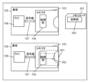
- FIG. 1 is a schematic diagram showing a memory card and a connector mounted on a board of a host device according to the first embodiment.
- the board 105 of the host device is equipped with a connector 103 into which the memory card 101 can be inserted and removed.
- the connector 103 includes a heat absorption section 104.
- the heat absorbing section 104 is made of a material with high thermal conductivity so as to efficiently conduct heat from the memory card 101 to the connector.
- the heat absorbing section 104 has a structure that comes into contact with the inserted memory card.
- a control unit capable of transmitting and receiving electrical signals is mounted on the board 105.
- SoC (System On Chip) 106 is an example of a control unit.
- the SoC 106 is connected to the connector 103 by a signal line 107, and an electrical signal from the SoC 106 can be transmitted to the connector 103.
- the SoC 106 can use the information.
- the host device further includes an air cooling fan 111. Note that the storage unit 110 and the air cooling fan 111 may not be shown in areas other than the upper part of FIG. 1 .
- a host device Normally, a host device requires a DRAM (Dynamic Random Access Memory) and other peripheral components, but these are omitted because they are not directly related to the content of this disclosure.
- DRAM Dynamic Random Access Memory
- the memory card 101 includes a heat dissipation section 102 for discharging heat within the memory card 101.
- the heat dissipation section 102 is made of a material with higher thermal conductivity than the casing of the memory card 101.
- the heat dissipation section 102 is located at a location where it contacts the heat absorption section 104 when inserted into the connector 103.
- Memory card 101 further includes a memory 108 and a processor 109.
- FIG. 1 shows a state in which the memory card 101 is inserted into the connector 103.
- the memory card 101 With the memory card 101 inserted into the connector 103 mounted on the board 105 of the host device, commands in the form of electrical signals from the SoC 106 are received by the memory card 101 via the connector 103.
- the memory card 101 is capable of analyzing the received electrical signal and transmitting an appropriate electrical signal response to the SoC 106.
- FIG. 11 shows a plan view and a sectional view of the connector 103 and the memory card 101.
- This sectional view is a diagram obtained by cutting the plan view along the AB plane.
- the cross section of the heat absorbing portion 104 is a semicylindrical shape in a spring state. That is, the shape of the heat absorbing portion 104 is a convex shape. This is to ensure that it is bonded to the heat dissipating portion 102 for heat dissipation.
- the signal terminal 1101 of the connector is arranged so as to be in contact with the signal terminal 1102 of the inserted memory card 101. Commands and responses are exchanged via this contact.
- FIG. 4 is a sequence diagram for explaining the operation of the host device and the memory card 101 inserted into the connector 103 of the board 105 of the host device.
- the memory card 101 is inserted into the connector 103 of the board 105 of the host device.
- the connector 103 is connected to the SoC 106 installed in the host device via a signal line 107, and notifies the SoC 106 of information that the memory card 101 has been inserted (S401).
- the SoC 106 detects insertion of the memory card 101 (S402). SoC 106 sends commands to memory card 101 via signal line 107. The memory card 101 analyzes the command and returns an appropriate response. Initialization processing is executed by repeating such commands and responses multiple times (S403). After the initialization process, the memory card 101 is in a state where data can be written, read, erased, etc.
- the SoC 106 issues a command to the memory card 101 to request heat dissipation section information (S404).
- the processor 109 of the memory card 101 returns a response including the heat dissipation section information stored in the memory 108 (S405).
- the SoC 106 calculates the heat dissipation performance from the heat dissipation section information included in the response and the heat absorption section information already held in the connector 103. For example, if the position of the heat radiating part 102 and the position of the heat absorbing part 104 match and the thermal conductivity of the materials of the heat radiating part 102 and the heat absorbing part 104 are high, it is calculated that the heat radiation performance is high (S406).
- the SoC 106 determines that it is possible to perform high-speed writing and high-speed reading that generate a large amount of heat (S407). Thereafter, the SoC 106 executes high-speed writing and high-speed reading to the memory card 101 as necessary (S408).
- FIG. 7 schematically shows the position of the heat dissipation section provided in the memory card.
- the heat dissipation section In the memory card 701 with the heat dissipation section at position A, the heat dissipation section is located at the front in the direction of insertion into the connector.
- the heat dissipation part In the memory card 702 with the heat dissipation part at position B, the heat dissipation part is located at the rear in the direction of insertion into the connector.
- the heat dissipation section In the memory card 703 at the heat dissipation section position C, the heat dissipation section is located over the entire surface.
- the heat dissipation part In the memory card 704 with the heat dissipation part located at position D, the heat dissipation part is located on the right side in the direction of insertion into the connector.
- the heat dissipation section In the memory card 705 with the heat dissipation section at position E, the
- FIG. 8 schematically shows the position of the heat absorbing part provided in the connector.
- the heat absorbing portion In the connector 801 having the heat absorbing portion at position A, the heat absorbing portion is located in front of the input direction of the memory card.
- the heat absorbing portion In the connector 802 at the heat absorbing portion position B, the heat absorbing portion is located at the rear in the input direction of the memory card.
- the heat absorbing portion In the connector 803 at the heat absorbing portion position C, the heat absorbing portion is positioned so as to cover the entire surface of the memory card.
- the heat absorbing part In the connector 804 at position D of the heat absorbing part, the heat absorbing part is located on the right side in the input direction of the memory card.
- the heat absorbing portion In the connector 805 at the heat absorbing portion position E, the heat absorbing portion is located on the left side in the input direction of the memory card.
- FIG. 9 is an example of how to represent information on the presence or absence of a heat radiating section (information indicating whether the memory card has a heat radiating section) and position information included in the response sent back by the memory card.
- the presence/absence and position information of the heat dissipation section represents the presence/absence and position information of the heat dissipation section provided in the memory card. If the value is "000”, the heat dissipation section is not provided, and if the value is "001", the heat dissipation section is provided, indicating that the memory card 701 is in the heat dissipation section position A.
- FIG. 10 is an example of how to represent material information included in the response sent back by the memory card.
- the name of the material of the heat dissipation section indicates the name of the material of the heat dissipation section provided in the memory card.
- a value of "000” indicates copper, and a value of "001" indicates aluminum.
- "010,” “011,” and “100” represent silver, gold, and epoxy resin, respectively.
- the thermal conductivity of the heat dissipation section represents the thermal conductivity of the heat dissipation section provided in the memory card. If the value is "000”, it means that it is 400 W/mK or more, and if it is "001", it means that it is 300 W/mK or more and less than 400 W/mK. Similarly, “010” and “011” represent 200 W/mK or more and less than 300 W/mK and less than 200 W/mK, respectively.
- the memory card 101 In response to a command from the SoC 106 requesting heat radiating part information, the memory card 101 returns a response including "001" indicating the presence or absence of the heat radiating part and its position information, and "000" indicating the material name of the heat radiating part. From this information, the SoC 106 can know that the memory card 701 is at the heat dissipation section position A and that its material is copper. The SoC 106 knows the information about the connector, and if the connector 801 is at the position A of the heat absorption part, it knows that the positions of the heat radiation part and the heat absorption part match. Furthermore, since the material is copper, it can be seen that it has high thermal conductivity. From this information, the SoC 106 can determine that the heat dissipation performance of the memory card 101 into which the connector is inserted is in a high state.
- the SoC 106 of the host device issues a command requesting heat dissipation section information to the inserted memory card 101.
- the memory card 101 replies to the SoC 106 with a response including heat dissipation section information.
- the SoC 106 of the host device can determine whether the inserted memory card 101 has high heat dissipation performance. Therefore, it becomes easier to determine the data writing speed and reading speed suitable for heat dissipation performance.
- Embodiment 2 Embodiment 2 will be described below with reference to FIGS. 2 and 5.
- FIG. 2 is a schematic diagram showing a memory card and a connector mounted on a host device board according to the second embodiment.
- the board 105 of the host device is equipped with a connector 103 into which a memory card 201 can be inserted and removed.
- the connector 103 includes a heat absorption section 104.
- the heat absorbing section 104 is made of a material with high thermal conductivity so as to efficiently conduct heat from the memory card 201 to the connector.
- the heat absorbing section 104 has a structure that comes into contact with the inserted memory card.
- a control unit capable of transmitting and receiving electrical signals is mounted on the board 105.
- SoC 106 is an example of a control unit.
- the SoC 106 is connected to the connector 103 by a signal line 107, and an electrical signal from the SoC 106 can be transmitted to the connector 103.
- Information such as the position and shape of the heat absorbing part 104 provided in the connector 103 is determined at the time of manufacture of the host device, so it is stored at the time of manufacture in a storage unit (not shown) such as a non-volatile memory installed separately in the host device.
- the SoC 106 can use this information.
- a host device Normally, a host device requires a DRAM and other peripheral components, but these are omitted because they are not directly related to the content of this disclosure.
- the memory card 201 does not include a heat radiating section for dissipating the heat inside the memory card 201.
- the memory card 201 With the memory card 201 inserted into the connector 103 mounted on the board 105 of the host device, commands in the form of electrical signals from the SoC 106 are received by the memory card 201 via the connector 103.
- the memory card 201 is capable of analyzing the received electrical signal and transmitting an appropriate electrical signal response to the SoC 106.
- FIG. 2 shows a state in which the memory card 201 is inserted into the connector 103.
- the shape of the connector 103 is the same as in Embodiment 1, so it will be omitted.
- FIG. 5 is a sequence diagram for explaining the operation of the host device and the memory card 201 inserted into the connector 103 of the board 105 of the host device.
- the memory card 201 is inserted into the connector 103 of the board 105 of the host device.
- the connector 103 is connected to the SoC 106 installed in the host device via a signal line 107, and notifies the SoC 106 of information that the memory card 201 has been inserted (S501).
- the SoC 106 detects insertion of the memory card 201 (S502).
- the SoC 106 installed in the host device sends commands to the memory card 201 via the signal line 107.
- the memory card 201 analyzes the command and returns an appropriate response.
- Initialization processing is executed by repeating such commands and responses multiple times (S503). After the initialization process, the memory card 201 is in a state where data can be written, read, erased, etc.
- the SoC 106 issues a command to the memory card 201 to request heat dissipation section information (S504).
- the memory card 201 returns a response including information on its own heat dissipation section (S505).
- the SoC 106 calculates the heat dissipation performance from the heat dissipation section information included in the response and the heat absorption section information already held in the connector 103. For example, if it is found that a heat dissipation section is not provided, the heat dissipation performance is calculated to be low (S506).
- the SoC 106 If it is determined that the heat dissipation performance is low, the SoC 106 gives up on high-speed writing and high-speed reading, which generate a large amount of heat, and determines that low-speed writing and low-speed reading can be executed continuously (S507). Thereafter, the SoC 106 executes low-speed writing and low-speed reading to the memory card 201 as necessary (S508).
- the information to be sent and received and the information used to calculate the heat dissipation performance are the same as in Embodiment 1, so only an example of determination will be shown. Let us take as an example a case where the material name shown in FIG. 10 is used as the material information of the heat dissipation part.
- the memory card 201 In response to the command requesting heat radiation part information from the SoC 106, the memory card 201 returns a response including "000" indicating the presence or absence of the heat radiation part and position information, and "100" the material name of the heat radiation part.
- the SoC 106 is a memory card that does not have a heat dissipation section, and that the material of the portion of the connector 103 that comes into contact with the heat absorption section is epoxy resin. Although the SoC 106 knows the information about the connector, since the memory card 201 does not have a heat dissipation section, it can be determined that the heat dissipation performance is low.
- the SoC 106 of the host device issues a command requesting heat dissipation section information to the inserted memory card 201.
- the memory card 201 replies to the SoC 106 a response that includes heat dissipation section information.
- the SoC 106 of the host device can determine whether the inserted memory card 201 has low heat dissipation performance. Therefore, it becomes easier to determine the data writing speed and reading speed suitable for heat dissipation performance.
- Embodiment 3 (Embodiment 3) Embodiment 3 will be described below with reference to FIGS. 3 and 6.
- FIG. 3 is a schematic diagram showing a memory card and a connector mounted on a host device board according to the third embodiment. The explanation will be based on the diagram shown in the upper part of FIG. 3 in which the memory card is removed.
- a board 105 of the host device is equipped with a connector 103 into which a memory card 301 can be inserted and removed.
- the connector 103 includes a heat absorption section 104.
- the heat absorbing section 104 is made of a material with high thermal conductivity so as to efficiently conduct heat from the memory card 301 to the connector.
- the heat absorbing portion 104 has a structure that comes into contact with the inserted memory card.
- a control unit capable of transmitting and receiving electrical signals is mounted on the board 105.
- SoC 106 is an example of a control unit.
- the SoC 106 is connected to the connector 103 by a signal line 107, and an electrical signal from the SoC 106 can be transmitted to the connector 103.
- Information such as the position and shape of the heat absorbing part 104 provided in the connector 103 is determined at the time of manufacture of the host device, so it is stored at the time of manufacture in a storage unit (not shown) such as a non-volatile memory installed separately in the host device.
- the SoC 106 can use this information.
- a host device requires a DRAM and other peripheral components, but these are omitted because they are not directly related to the content of this disclosure.
- the memory card 301 includes a heat radiating section 302 for discharging heat within the memory card 301.
- the heat dissipation section 302 is made of a material with higher thermal conductivity than the casing of the memory card 301.
- the position of the heat dissipation section 302 is such that it is in partial contact with the heat absorption section 104 when inserted into the connector 103.
- FIG. 3 shows a state in which the memory card 301 is inserted into the connector 103.
- the shape of connector 103 is the same as in Embodiment 1, so it will be omitted.
- FIG. 6 is a sequence diagram for explaining the operation of the host device and the memory card 301 inserted into the connector 103 of the board 105 of the host device.
- the memory card 301 is inserted into the connector 103 of the board 105 of the host device.
- the connector 103 is connected to the SoC 106 installed in the host device via a signal line 107, and notifies the SoC 106 of information that the memory card 301 has been inserted (S601).
- the SoC 106 detects insertion of the memory card 301 (S602).
- the SoC 106 installed in the host device transmits commands to the memory card 301 via the signal line 107.
- the memory card 301 analyzes the command and returns an appropriate response. This command/response is repeated multiple times to execute initialization processing (S603). After the initialization process, the memory card 301 is in a state where data can be written, read, erased, etc.
- the SoC 106 issues a command to the memory card 301 to request heat dissipation section information (S604).
- the memory card 301 returns a response including information on its own heat dissipation section (S605).
- the SoC 106 calculates the heat dissipation performance from the heat dissipation section information included in the response and the heat absorption section information already held in the connector 103. For example, if the position of the heat radiation part and the position of the heat absorption part partially match and the thermal conductivity of the materials of the heat radiation part and the heat absorption part are high, the heat radiation performance is calculated to be medium (S606).
- the SoC 106 determines that medium-speed writing and medium-speed reading with moderate heat generation are possible (S607). Thereafter, the SoC 106 executes medium-speed writing and medium-speed reading to the memory card 301 as necessary (S608).
- the information to be sent and received and the information used to calculate the heat dissipation performance are the same as in Embodiment 1, so only an example of determination will be shown.
- the memory card 301 In response to the command requesting heat radiation part information from the SoC 106, the memory card 301 returns a response that includes the presence/absence and position information of the heat radiation part as "100" and the material name of the heat radiation part "010". From this information, the SoC 106 can know that the memory card 701 is at the heat dissipation section position A and that its material is copper. The SoC 106 knows the information about the connector, and knows that if the connector 801 is at the heat absorption part position A, the positions of the heat radiation part and the heat absorption part partially match, and the heat radiation performance is medium.
- the SoC 106 can determine that the heat dissipation performance of the memory card 301 into which the connector is inserted is in a medium state.
- the SoC 106 of the host device issues a command requesting heat radiation part information to the inserted memory card 301.
- the memory card 301 replies to the SoC 106 a response that includes heat dissipation section information.
- the SoC 106 of the host device can determine whether the heat dissipation performance of the inserted memory card 301 is in a medium state. Therefore, it becomes easier to determine the data writing speed and reading speed suitable for heat dissipation performance.
- Embodiments 1 to 3 have been described as examples of the technology disclosed in this application.
- the technology in the present disclosure is not limited to this, and can also be applied to embodiments in which changes, replacements, additions, omissions, etc. are made.
- the position and material of the heat radiating part were explained as information for calculating the performance of the heat radiating part.
- the information for calculating the performance of the heat dissipation section may be any information that affects heat dissipation, and therefore, this information is not limited to the position and material of the heat dissipation section.
- the shape such as the length and width of the heat dissipation part, the shape of the memory card itself, the surface area of the memory card itself, whether the memory card is equipped with fins, and if so, the direction of the fins, etc. may be used.
- the connector may be any connector that can be used to attach and detach a non-volatile memory, and therefore is not limited to a shape that allows a memory card to be inserted.
- M M.
- a connector like 2 may also be used.
- the host device limited the write speed to the memory card and the read speed from the memory card based on the calculated heat dissipation performance. There is no problem with the actions that the host device performs based on the calculated heat dissipation performance, even if they are to compensate for the lack of heat dissipation performance.For example, opening the host device's casing door to lower the temperature around the memory card.
- the operation may be performed by operating the air cooling fan 111 installed in the host device, increasing the rotation speed of the air cooling fan 111, or the like. That is, the host device controls the air cooling fan 111 based on the calculated heat radiation performance as an operation to supplement the heat radiation performance of the memory card. Alternatively, a warning of insufficient heat dissipation performance may be notified to the host device user.
- the present disclosure is applicable to devices that write and read data while generating heat at high temperatures. Specifically, the present disclosure is applicable to digital cameras, movies, smartphones, drones, and the like.
Abstract
メモリーカードは、ホスト機器に具備されているコネクタに挿抜可能なメモリーカードであって、メモリーカードの放熱部に関する放熱部情報を格納するメモリと、ホスト機器から送信された、放熱性能を問い合わせるコマンドに対して、放熱部情報を含むレスポンスを返信するプロセッサを備える。
Description
本開示は、放熱性能を向上させたメモリーカードおよびホスト機器に関する。
特許文献1は、携帯用コンピュータに対する差込み機能モジュールからの熱放散を管理するための装置、また、ドッキングされたモジュールを解放するユーザーが操作可能な解放手段を開示する。この装置は、無駄な熱を取り出すようにドッキングしたモジュールと接触できるように変形可能な熱シンク構造を備えた装置を備える。これにより機能モジュールから無駄な熱を吸収することができる。
本開示は、メモリーカードを装着するホスト機器とメモリーカード間で適切なやり取りを行い、ホスト機器が放熱性能を考慮した制御を実現可能なメモリーカードを提供する。
本開示の一態様は、ホスト機器に具備されているコネクタに挿抜可能なメモリーカードであって、メモリーカードの放熱部に関する放熱部情報を格納するメモリと、ホスト機器から送信された、放熱性能を問い合わせるコマンドに対して、放熱部情報を含むレスポンスを返信するプロセッサを備えるメモリーカードを提供する。
本開示のメモリーカードは、ホスト機器とのやり取りにおいて放熱性能を考慮した制御を実現することができる。
以下、適宜図面を参照しながら、実施の形態を詳細に説明する。但し、必要以上に詳細な説明は省略する場合がある。例えば、既によく知られた事項の詳細説明や実質的に同一の構成に対する重複説明を省略する場合がある。これは、以下の説明が不必要に冗長になるのを避け、当業者の理解を容易にするためである。
なお、添付図面および以下の説明は、当業者が本開示を十分に理解するために、提供されるのであって、これらにより特許請求の範囲に記載の主題を限定することは意図されていない。
(実施の形態1)
以下、図1、図4,図7~11を用いて、実施の形態1を説明する。
以下、図1、図4,図7~11を用いて、実施の形態1を説明する。
[1-1.構成]
図1は、実施の形態1にかかるメモリーカードとホスト機器の基板に搭載されているコネクタを示す模式図である。
図1は、実施の形態1にかかるメモリーカードとホスト機器の基板に搭載されているコネクタを示す模式図である。
図1の上段に記載しているメモリーカード101が抜去された状態の図を基に説明する。
ホスト機器の基板105は、メモリーカード101を挿抜可能なコネクタ103を搭載する。コネクタ103は、吸熱部104を備える。吸熱部104は、メモリーカード101から熱をコネクタに効率よく伝導するよう熱伝導率の高い材質で作成されている。吸熱部104は、挿入されたメモリーカードに接する構造である。また、基板105には、電気信号を送受信可能な制御部が搭載される。SoC(System On Chip)106は制御部の一例である。SoC106は、コネクタ103と信号線107で接続されており、SoC106からの電気信号をコネクタ103に伝えることが可能である。コネクタ103に備わっている吸熱部104の位置、形状などの情報(吸熱部情報)は、ホスト機器の製造時に決定されるため、ホスト機器に搭載されている不揮発メモリ等の記憶部110に製造時に記憶して、それら情報を保持しており、SoC106はその情報を利用可能である。ホスト機器は、空冷ファン111をさらに備える。なお、図1の上段以外において、記憶部110と空冷ファン111を図示しない場合がある。
通常、ホスト機器には、DRAM(Dynamic Randam Access Memory)や、その他周辺部品などが必要であるが、本開示の内容とは直接関係が無いため省略している。
メモリーカード101は、メモリーカード101内の熱を放出する為の放熱部102を備える。放熱部102は、メモリーカード101の筐体よりも熱伝導率が高い材質で作成されている。放熱部102の位置は、コネクタ103に挿入された時に、吸熱部104に接する場所である。メモリーカード101は、メモリ108と、プロセッサ109とをさらに備える。
図1の下段には、メモリーカード101がコネクタ103に挿入されている状態の図を表している。
メモリーカード101がホスト機器の基板105に搭載されているコネクタ103に挿入された状態で、SoC106からの電気信号によるコマンドは、コネクタ103を経由しメモリーカード101に受信される。メモリーカード101は、受信した電気信号を解析し、適切な電気信号によるレスポンスを、SoC106に送信することが可能である。
図11を用いてコネクタ103の形状を説明する。図11は、コネクタ103とメモリーカード101の平面図と断面図を表している。この断面図は、平面図をA-B面で切断した図である。吸熱部104の断面は、ばね状態のかまぼこ型である。すなわち、吸熱部104の形状は、凸形状である。これは放熱部102と放熱の為には確実に接着させるためである。
コネクタの信号端子1101は、挿入されたメモリーカード101の信号端子1102に接するように配置されている。この接点を経由してコマンド、レスポンスはやり取りされる。
図11の断面図には信号端子が1つしか描かれていないが、複数端子存在する。また、通常コネクタ103には、別途必要な部品、機構が存在するが本開示の内容とは直接関係が無いため省略している。
[1-2-1.動作]
以上のように構成されたメモリーカード101について、その動作を以下の通り説明する。
以上のように構成されたメモリーカード101について、その動作を以下の通り説明する。
図4は、ホスト機器とホスト機器の基板105のコネクタ103に挿入されたメモリーカード101との動作を説明するためのシーケンス図である。
メモリーカード101は、ホスト機器の基板105のコネクタ103に挿入にされる。コネクタ103は、ホスト機器に搭載されているSoC106と信号線107で繋がっており、メモリーカード101が挿入されたという情報をSoC106に通知する(S401)。
SoC106は、メモリーカード101の挿入を検出する(S402)。SoC106は、信号線107を経由してコマンドをメモリーカード101に送信する。メモリーカード101は、コマンドを解析し適切なレスポンスを返信する。このようなコマンドとレスポンスを複数回繰り返して、初期化処理を実行する(S403)。初期化処理後には、メモリーカード101は、データの書込み、読出し、消去などが実行できる状態になる。
SoC106は、メモリーカード101に、放熱部情報を要求するコマンドを発行する(S404)。メモリーカード101のプロセッサ109は、メモリ108に格納された放熱部情報を含んだレスポンスを返信する(S405)。SoC106は、レスポンスに含まれている放熱部情報と既に保持しているコネクタ103に備わっている吸熱部情報から、放熱性能を算出する。例えば、放熱部102の位置と吸熱部104の位置が一致し、放熱部102と吸熱部104の材質の熱伝導率が高ければ、放熱性能は高いと算出とする(S406)。
放熱性能が高いと判断した場合、SoC106は発熱の大きい高速書込み、高速読出しを実行可能と判断する(S407)。その後、必要に応じてSoC106は、メモリーカード101に対して高速書込み、高速読出しを実行する(S408)。
[1-2-2.送受信する情報と放熱性能の算出]
図7~図10を用いて、ホスト基板に搭載されているSoC106とメモリーカード101の間でやり取りする放熱部情報について説明する。
図7~図10を用いて、ホスト基板に搭載されているSoC106とメモリーカード101の間でやり取りする放熱部情報について説明する。
図7は、メモリーカードに備わっている放熱部の位置を模式的に表したものである。放熱部の位置Aのメモリーカード701は、コネクタへの挿入方向前方に放熱部が位置している。放熱部の位置Bのメモリーカード702は、コネクタへの挿入方向後方に放熱部が位置している。放熱部の位置Cのメモリーカード703は、全面に渡って放熱部が位置している。放熱部の位置Dのメモリーカード704は、コネクタへの挿入方向右側に放熱部が位置している。放熱部の位置Eのメモリーカード705は、コネクタへの挿入方向左側に放熱部が位置している。
図8は、コネクタに備わっている吸熱部の位置を模式的に表したものである。吸熱部の位置Aのコネクタ801は、メモリーカードの入力方向前方に吸熱部が位置している。吸熱部の位置Bのコネクタ802は、メモリーカードの入力方向後方に吸熱部が位置している。吸熱部の位置Cのコネクタ803は、メモリーカード全面を覆うように吸熱部が位置している。吸熱部の位置Dのコネクタ804は、メモリーカードの入力方向右側に吸熱部が位置している。吸熱部の位置Eのコネクタ805は、メモリーカードの入力方向左側に吸熱部が位置している。
図9は、メモリーカードが返信するレスポンスに含まれる放熱部の有無の情報(メモリーカードが放熱部を有するか否かを示す情報)と位置情報の表し方の例である。放熱部の有無と位置情報は、メモリーカードに備わっている放熱部の有無と位置情報を表している。値が「000」であれば放熱部は備わっておらず、「001」であれば放熱部は備わっており、放熱部位置Aのメモリーカード701であることを表している。また、「010」であれば放熱部は備わっており、放熱部位置Bのメモリーカード702であることを表している。同様に、「001」「100」「101」はそれぞれ、放熱部位置Cのメモリーカード703、放熱部位置Dのメモリーカード704、放熱部位置Eのメモリーカード705であることを表している。
図10は、メモリーカードが返信するレスポンスに含まれる材質情報の表し方の例である。放熱部の材質名は、メモリーカードに備わっている放熱部の材質名を表している。値が「000」であれば、銅であること、「001」であればアルミニウムであることを表している。同様に、「010」「011」「100」はそれぞれ、銀、金、エポキシ樹脂を表す。
放熱部の熱伝導率は、メモリーカードに備わっている放熱部の熱伝導率を表している。値が「000」であれば、400W/mK以上であること、「001」であれば300W/mK以上400W/mK未満であることを表している。同様に、「010」「011」はそれぞれ、200W/mK以上300W/mK未満、200W/mK未満を表す。
放熱部の材質情報として図10で示す材質名を使用している場合を例にとる。SoC106からの放熱部情報を要求するコマンドに対して、メモリーカード101は、放熱部の有無と位置情報を「001」、放熱部の材質名「000」を含むレスポンスを返信する。SoC106は、この情報から放熱部位置Aのメモリーカード701であり、その材質は銅であることを知ることができる。SoC106はコネクタの情報を知っており、吸熱部の位置Aのコネクタ801であれば、放熱部と吸熱部の位置が一致していることを知る。さらに材質が銅であるため、熱伝導率が高いことが分かる。これらの情報から、SoC106は、コネクタの挿入されたメモリーカード101の放熱性能が高い状態であると判断できる。
[1-3.効果等]
以上のように、実施の形態1において、ホスト装置のSoC106は、挿入されたメモリーカード101に、放熱部情報を要求するコマンドを発行する。メモリーカード101は、SoC106に放熱部情報を含んだレスポンスを返信する。これにより、ホスト装置のSoC106は、挿入されたメモリーカード101が放熱性能の高い状態であるかを判断することができる。そのため、放熱性能に適したデータの書込み速度、読出し速度を決定しやすくなる。
以上のように、実施の形態1において、ホスト装置のSoC106は、挿入されたメモリーカード101に、放熱部情報を要求するコマンドを発行する。メモリーカード101は、SoC106に放熱部情報を含んだレスポンスを返信する。これにより、ホスト装置のSoC106は、挿入されたメモリーカード101が放熱性能の高い状態であるかを判断することができる。そのため、放熱性能に適したデータの書込み速度、読出し速度を決定しやすくなる。
(実施の形態2)
以下、図2、図5を用いて、実施の形態2を説明する。
以下、図2、図5を用いて、実施の形態2を説明する。
[2-1.構成]
図2は、実施の形態2にかかるメモリーカードとホスト機器基板に搭載されているコネクタを示す模式図である。
図2は、実施の形態2にかかるメモリーカードとホスト機器基板に搭載されているコネクタを示す模式図である。
図2の上段に記載の、メモリーカードが抜去された状態の図を基に説明する。
ホスト機器の基板105は、メモリーカード201を挿抜可能なコネクタ103を搭載する。コネクタ103は、吸熱部104を備える。吸熱部104は、メモリーカード201から熱をコネクタに効率よく伝導するよう熱伝導率の高い材質で作成されている。吸熱部104は、挿入されたメモリーカードに接する構造である。また、基板105には、電気信号を送受信可能な制御部が搭載される。SoC106は制御部の一例である。SoC106は、コネクタ103と信号線107で接続されており、SoC106からの電気信号をコネクタ103に伝えることが可能である。コネクタ103に備わっている吸熱部104の位置、形状などの情報は、ホスト機器の製造時に決定されるため、別途ホスト機器に搭載されている不揮発メモリ等の図示していない記憶部に製造時に記憶して、それら情報を保持しており、SoC106はその情報を利用可能である。
通常、ホスト機器には、DRAMや、その他周辺部品などが必要であるが、本開示の内容とは直接関係が無いため省略している。
メモリーカード201は、メモリーカード201内の熱を放出する為の放熱部を備えていない。
メモリーカード201がホスト機器の基板105に搭載されているコネクタ103に挿入された状態で、SoC106からの電気信号によるコマンドは、コネクタ103を経由しメモリーカード201に受信される。メモリーカード201は受信した電気信号を解析し、適切な電気信号によるレスポンスを、SoC106に送信することが可能である。
図2の下段には、メモリーカード201がコネクタ103に挿入されている状態の図を表している。
コネクタ103の形状は、実施の形態1と同様であるため、省略する。
[2-2.動作]
以上のように構成されたメモリーカード201について、その動作を以下の通り説明する。図5は、ホスト機器とホスト機器の基板105のコネクタ103に挿入されたメモリーカード201との動作を説明するためのシーケンス図である。メモリーカード201は、ホスト機器の基板105のコネクタ103に挿入にされる。コネクタ103は、ホスト機器に搭載されているSoC106と信号線107で繋がっており、メモリーカード201が挿入されたという情報をSoC106に通知する(S501)。
以上のように構成されたメモリーカード201について、その動作を以下の通り説明する。図5は、ホスト機器とホスト機器の基板105のコネクタ103に挿入されたメモリーカード201との動作を説明するためのシーケンス図である。メモリーカード201は、ホスト機器の基板105のコネクタ103に挿入にされる。コネクタ103は、ホスト機器に搭載されているSoC106と信号線107で繋がっており、メモリーカード201が挿入されたという情報をSoC106に通知する(S501)。
SoC106は、メモリーカード201の挿入を検出する(S502)。ホスト機器に搭載されているSoC106は、信号線107を経由してコマンドをメモリーカード201に送信する。メモリーカード201は、コマンドを解析し適切なレスポンスを返信する。このようなコマンドとレスポンスを複数回繰り返して、初期化処理を実行する(S503)。初期化処理後には、メモリーカード201は、データの書込み、読出し、消去などが実行できる状態になる。
SoC106は、メモリーカード201に、放熱部情報を要求するコマンドを発行する(S504)。メモリーカード201は、自身に備わっている放熱部情報を含んだレスポンスを返信する(S505)。SoC106は、レスポンスに含まれている放熱部情報と既に保持しているコネクタ103に備わっている吸熱部情報から、放熱性能を算出する。例えば、放熱部を備えていないことが分かれば、放熱性能は低いと算出とする(S506)。
放熱性能が低いと判断した場合、SoC106は発熱の大きい高速書込み、高速読出しをあきらめ、低速書込み、低速読出しであれば連続実行可能と判断する(S507)。その後、必要に応じてSoC106は、メモリーカード201に対して低速書込み、低速読出しを実行する(S508)。
送受信する情報と放熱性能の算出に用いる情報については、実施の形態1と同様であるため、判断例についてのみ示す。放熱部の材質情報として、図10で示す材質名を使用している場合を例にとる。SoC106からの放熱部情報を要求するコマンドに対して、メモリーカード201は、放熱部の有無と位置情報を「000」、放熱部の材質名「100」を含むレスポンスを返信する。SoC106はこの情報から、放熱部を備えていないメモリーカードであり、コネクタ103の吸熱部に接する部分の材質は、エポキシ樹脂であることを知ることができる。SoC106はコネクタの情報を知っているが、メモリーカード201には放熱部が備わっていないことから、放熱性能が低い状態であると判断できる。
[2-3.効果等]
以上のように、実施の形態2において、ホスト装置のSoC106は、挿入されたメモリーカード201に、放熱部情報を要求するコマンドを発行する。メモリーカード201は、SoC106に、放熱部情報を含んだレスポンスを返信する。
以上のように、実施の形態2において、ホスト装置のSoC106は、挿入されたメモリーカード201に、放熱部情報を要求するコマンドを発行する。メモリーカード201は、SoC106に、放熱部情報を含んだレスポンスを返信する。
これにより、ホスト装置のSoC106は、挿入されたメモリーカード201が放熱性能の低い状態であるかを判断することができる。そのため、放熱性能に適したデータの書込み速度、読出し速度を決定しやすくなる。
(実施の形態3)
以下、図3、図6を用いて、実施の形態3を説明する。
以下、図3、図6を用いて、実施の形態3を説明する。
[3-1.構成]
図3は、実施の形態3にかかるメモリーカードとホスト機器基板に搭載されているコネクタを示す模式図である。図3の上段に記載の、メモリーカードが抜去された状態の図を基に説明する。ホスト機器の基板105は、メモリーカード301を挿抜可能なコネクタ103を搭載する。コネクタ103は、吸熱部104を備える。吸熱部104はメモリーカード301から熱をコネクタに効率よく伝導するよう熱伝導率の高い材質で作成されている。吸熱部104、は挿入されたメモリーカードに接する構造である。また、基板105には、電気信号を送受信可能な制御部が搭載される。SoC106は制御部の一例である。SoC106は、コネクタ103と信号線107で接続されており、SoC106からの電気信号をコネクタ103に伝えることが可能である。コネクタ103に備わっている吸熱部104の位置、形状などの情報は、ホスト機器の製造時に決定されるため、別途ホスト機器に搭載されている不揮発メモリ等の図示していない記憶部に製造時に記憶して、それら情報を保持しており、SoC106はその情報を利用可能である。通常、ホスト機器には、DRAMや、その他周辺部品などが必要であるが、本開示の内容とは直接関係が無いため省略している。メモリーカード301は、メモリーカード301内の熱を放出する為の放熱部302を備える。放熱部302は、メモリーカード301の筐体よりも熱伝導率が高い材質で作成されている。放熱部302の位置は、コネクタ103に挿入された時に、吸熱部104に部分的に接する場所である。メモリーカード301がホスト機器の基板105に搭載されているコネクタ103に挿入された状態で、SoC106からの電気信号によるコマンドは、コネクタ103を経由しメモリーカード301に受信される。メモリーカード301は受信した電気信号を解析し、適切な電気信号によるレスポンスを、SoC106に送信することが可能である。
図3は、実施の形態3にかかるメモリーカードとホスト機器基板に搭載されているコネクタを示す模式図である。図3の上段に記載の、メモリーカードが抜去された状態の図を基に説明する。ホスト機器の基板105は、メモリーカード301を挿抜可能なコネクタ103を搭載する。コネクタ103は、吸熱部104を備える。吸熱部104はメモリーカード301から熱をコネクタに効率よく伝導するよう熱伝導率の高い材質で作成されている。吸熱部104、は挿入されたメモリーカードに接する構造である。また、基板105には、電気信号を送受信可能な制御部が搭載される。SoC106は制御部の一例である。SoC106は、コネクタ103と信号線107で接続されており、SoC106からの電気信号をコネクタ103に伝えることが可能である。コネクタ103に備わっている吸熱部104の位置、形状などの情報は、ホスト機器の製造時に決定されるため、別途ホスト機器に搭載されている不揮発メモリ等の図示していない記憶部に製造時に記憶して、それら情報を保持しており、SoC106はその情報を利用可能である。通常、ホスト機器には、DRAMや、その他周辺部品などが必要であるが、本開示の内容とは直接関係が無いため省略している。メモリーカード301は、メモリーカード301内の熱を放出する為の放熱部302を備える。放熱部302は、メモリーカード301の筐体よりも熱伝導率が高い材質で作成されている。放熱部302の位置は、コネクタ103に挿入された時に、吸熱部104に部分的に接する場所である。メモリーカード301がホスト機器の基板105に搭載されているコネクタ103に挿入された状態で、SoC106からの電気信号によるコマンドは、コネクタ103を経由しメモリーカード301に受信される。メモリーカード301は受信した電気信号を解析し、適切な電気信号によるレスポンスを、SoC106に送信することが可能である。
図3の下段には、メモリーカード301がコネクタ103に挿入されている状態の図を表している。コネクタ103の形状は、実施の形態1と同様であるため、省略する。
[3-2.動作]
以上のように構成されたメモリーカード301について、その動作を以下の通り説明する。図6は、ホスト機器とホスト機器の基板105のコネクタ103に挿入されたメモリーカード301との動作を説明するためのシーケンス図である。メモリーカード301は、ホスト機器の基板105のコネクタ103に挿入にされる。コネクタ103は、ホスト機器に搭載されているSoC106と信号線107で繋がっており、メモリーカード301が挿入されたという情報をSoC106に通知する(S601)。
以上のように構成されたメモリーカード301について、その動作を以下の通り説明する。図6は、ホスト機器とホスト機器の基板105のコネクタ103に挿入されたメモリーカード301との動作を説明するためのシーケンス図である。メモリーカード301は、ホスト機器の基板105のコネクタ103に挿入にされる。コネクタ103は、ホスト機器に搭載されているSoC106と信号線107で繋がっており、メモリーカード301が挿入されたという情報をSoC106に通知する(S601)。
SoC106は、メモリーカード301の挿入を検出する(S602)。ホスト機器に搭載されているSoC106は、信号線107を経由してコマンドをメモリーカード301に送信する。メモリーカード301は、コマンドを解析し適切なレスポンスを返信する。このコマンド・レスポンスを複数回繰り返して、初期化処理を実行する(S603)。初期化処理後には、メモリーカード301は、データの書込み、読出し、消去などが実行できる状態になる。
SoC106は、メモリーカード301に、放熱部情報を要求するコマンドを発行する(S604)。メモリーカード301は、自身に備わっている放熱部情報を含んだレスポンスを返信する(S605)。SoC106は、レスポンスに含まれている放熱部情報と既に保持しているコネクタ103に備わっている吸熱部情報から、放熱性能を算出する。例えば、放熱部の位置と吸熱部の位置が部分的に一致し、放熱部と吸熱部の材質の熱伝導率が高ければ、放熱性能は中程度と算出とする(S606)。
放熱性能が高いと判断した場合、SoC106は発熱が中程度の中速書込み、中速読出しを実行可能と判断する(S607)。その後、必要に応じてSoC106は、メモリーカード301に対して中速書込み、中速読出しを実行する(S608)。
送受信する情報と放熱性能の算出に用いる情報については、実施の形態1と同様であるため、判断例についてのみ示す。
放熱部の材質情報として、図10で示す材質名を使用している場合を例にとる。SoC106からの放熱部情報を要求するコマンドに対して、メモリーカード301は、放熱部の有無と位置情報を「100」、放熱部の材質名「010」を含むレスポンスを返信する。SoC106はこの情報から、放熱部位置Aのメモリーカード701であり、その材質は銅であることを知ることができる。SoC106はコネクタの情報を知っており、吸熱部の位置Aのコネクタ801であれば、放熱部と吸熱部の位置が部分的に一致して、放熱性能が中程度であることを知る。さらに材料の熱伝導率が200W/mK以上300W/mK未満であるため、熱伝導率も中程度であることが分かる。これらの情報から、SoC106は、コネクタの挿入されたメモリーカード301の放熱性能が中程度の状態であると判断できる。
[3-3.効果等]
以上のように、実施の形態3において、ホスト装置のSoC106は挿入されたメモリーカード301に、放熱部情報を要求するコマンドを発行する。メモリーカード301は、SoC106に、放熱部情報を含んだレスポンスを返信する。
以上のように、実施の形態3において、ホスト装置のSoC106は挿入されたメモリーカード301に、放熱部情報を要求するコマンドを発行する。メモリーカード301は、SoC106に、放熱部情報を含んだレスポンスを返信する。
これにより、ホスト装置のSoC106は、挿入されたメモリーカード301の放熱性能が中程度の状態であるかを判断することができる。そのため、放熱性能に適したデータの書込み速度、読出し速度を決定しやすくなる。
(他の実施の形態)
以上のように、本出願において開示する技術の例示として、実施の形態1~3を説明した。しかしながら、本開示における技術は、これに限定されず、変更、置き換え、付加、省略などを行った実施の形態にも適用できる。また、上記実施の形態1~3で説明した各構成要素を組み合わせて、新たな実施の形態とすることも可能である。
以上のように、本出願において開示する技術の例示として、実施の形態1~3を説明した。しかしながら、本開示における技術は、これに限定されず、変更、置き換え、付加、省略などを行った実施の形態にも適用できる。また、上記実施の形態1~3で説明した各構成要素を組み合わせて、新たな実施の形態とすることも可能である。
そこで、以下、他の実施の形態を例示する。
実施の形態1~3では、放熱部能力の性能を算出する為の情報として、放熱部の位置、材質を説明した。放熱部の性能を算出する為の情報は、放熱に影響を与える情報であればよく、したがって、この情報は、放熱部の位置、材質に限定されない。例えは、放熱部の縦横の長さなどの形状、メモリーカード自身の形状、メモリーカード自身の表面積、メモリーカードにフィンが備わっているか否か、備わっているならばフィンの向き等でも良い。
実施の形態1~3では、メモリーカードを挿入する形状のコネクタを説明した。コネクタは、不揮発性メモリ化を脱着できるコネクタであればよく、したがって、メモリーカードを挿入する形状に限定されない。例えば、M.2のようなコネクタでも良い。
実施の形態1~3では、ホスト機器は算出した放熱性能からホスト機器はメモリーカードへの書込み速度、および、メモリーカードからの読出し速度を制限した。算出した放熱性能を元にホスト機器が行う動作は、不足した放熱性能を補うための動作であっても問題なく、例えば、メモリーカード周辺温度を下げる為にホスト機器の筐体の扉を開ける、ホスト機器に搭載されている空冷ファン111を動作させる、空冷ファン111の回転数を上げる等の動作で良い。すなわち、ホスト機器は、算出した放熱性能をもとに、メモリーカードの放熱性能を補う動作として、空冷ファン111を制御する。また、ホスト機器ユーザーに放熱性能不足の警告を通知でも良い。
なお、上述の実施の形態は、本開示における技術を例示するためのものであるから、特許請求の範囲またはその均等の範囲において種々の変更、置き換え、付加、省略などを行うことができる。
本開示は、高温下で発熱をしながらデータを書込み、読出しを行う装置に適用可能である。具体的には、デジタルカメラ、ムービー、スマートフォン、ドローンなどに、本開示は適用可能である。
101、201、301、701、702、703、704、705 メモリーカード
102、302 放熱部
103、801、802、803、804、805 コネクタ
104 吸熱部
105 基板
106 SoC
107 信号線
108 メモリ
109 プロセッサ
110 記憶部
111 空冷ファン
1101 信号端子
1102 信号端子
102、302 放熱部
103、801、802、803、804、805 コネクタ
104 吸熱部
105 基板
106 SoC
107 信号線
108 メモリ
109 プロセッサ
110 記憶部
111 空冷ファン
1101 信号端子
1102 信号端子
Claims (12)
- ホスト機器に具備されているコネクタに挿抜可能なメモリーカードであって、
前記メモリーカードの放熱部に関する放熱部情報を格納するメモリと、
前記ホスト機器から送信された、放熱性能を問い合わせるコマンドに対して、前記放熱部情報を含むレスポンスを返信するプロセッサと、を備えるメモリーカード。 - ホスト機器に具備されているコネクタに挿抜可能なメモリーカードであって、
前記メモリーカードの放熱部に関する放熱部情報を格納するメモリと、
前記ホスト機器から送信された初期化コマンドを受け付け、前記ホスト機器にレスポンスの返信を繰り返して初期化処理を完了し、その後、前記ホスト機器から送信された、放熱性能を問い合わせるコマンドに対して、前記放熱部情報を含むレスポンスを返信するプロセッサと、を備えるメモリーカード。 - 前記放熱部情報は、前記メモリーカードが放熱部を有するか否かを示す情報である請求項1または2に記載のメモリーカード。
- 前記放熱部情報は、前記放熱部の位置の情報である請求項1または2に記載のメモリーカード。
- 前記放熱部情報は、前記放熱部の形状の情報である請求項1または2に記載のメモリーカード。
- 前記放熱部情報は、前記放熱部の材質の情報である請求項1または2に記載のメモリーカード。
- 前記放熱部情報は、前記メモリーカードが放熱部を有するか否かを示す情報、前記放熱部の位置の情報、前記放熱部の形状の情報および前記放熱部の材質の情報の組み合わせである請求項1または2に記載のメモリーカード。
- 吸熱部を有し、メモリーカードを挿抜するコネクタと、
前記吸熱部の位置、形状、材質を示す吸熱部情報を保持する記憶部と、
前記吸熱部情報を利用することが可能な制御部とを備え、
前記制御部は、前記メモリーカードの放熱性能を問い合わせるコマンドを発行し、前記コマンドに対して前記メモリーカードから放熱部情報が含まれるレスポンスを受信し、前記吸熱部情報と前記放熱部情報から放熱性能を算出するホスト機器。 - 前記制御部は、前記放熱性能をもとに、前記メモリーカードへの書込み速度及び前記メモリーカードからの読出し速度を制限する請求項8に記載のホスト機器。
- 前記制御部は、前記放熱性能をもとに、前記メモリーカードの放熱性能を補う動作をする請求項8または9に記載のホスト機器。
- ファンをさらに備え、
前記制御部は、前記放熱性能をもとに、前記メモリーカードの放熱性能を補う動作として、前記ファンを制御する請求項10に記載のホスト機器。 - 前記吸熱部の形状は、凸形状である請求項8から11のいずれか1項に記載のホスト機器。
Applications Claiming Priority (2)
| Application Number | Priority Date | Filing Date | Title |
|---|---|---|---|
| JP2022040888 | 2022-03-16 | ||
| JP2022-040888 | 2022-03-16 |
Publications (1)
| Publication Number | Publication Date |
|---|---|
| WO2023176177A1 true WO2023176177A1 (ja) | 2023-09-21 |
Family
ID=88022784
Family Applications (1)
| Application Number | Title | Priority Date | Filing Date |
|---|---|---|---|
| PCT/JP2023/003075 WO2023176177A1 (ja) | 2022-03-16 | 2023-01-31 | メモリーカードおよびホスト機器 |
Country Status (1)
| Country | Link |
|---|---|
| WO (1) | WO2023176177A1 (ja) |
Citations (1)
| Publication number | Priority date | Publication date | Assignee | Title |
|---|---|---|---|---|
| WO2005015406A1 (ja) * | 2003-08-06 | 2005-02-17 | Matsushita Electric Industrial Co., Ltd. | 半導体メモリカード、アクセス装置及びアクセス方法 |
-
2023
- 2023-01-31 WO PCT/JP2023/003075 patent/WO2023176177A1/ja unknown
Patent Citations (1)
| Publication number | Priority date | Publication date | Assignee | Title |
|---|---|---|---|---|
| WO2005015406A1 (ja) * | 2003-08-06 | 2005-02-17 | Matsushita Electric Industrial Co., Ltd. | 半導体メモリカード、アクセス装置及びアクセス方法 |
Similar Documents
| Publication | Publication Date | Title |
|---|---|---|
| KR101994931B1 (ko) | 기억 장치 | |
| US10289174B2 (en) | Solid state drive apparatus | |
| US20060056151A1 (en) | System for cooling interior and external housing surfaces of an electronic apparatus | |
| JP3813281B2 (ja) | Icカードスロットを有する電子装置 | |
| US20140036435A1 (en) | Storage system having a heatsink | |
| TW201127271A (en) | Card-type peripheral apparatus | |
| US10638625B2 (en) | Solid state drive apparatus and data storage system having the same | |
| US10856441B1 (en) | System and method for bi-side heating vapor chamber structure in an information handling system | |
| JP2011181731A (ja) | カード状部品用ソケットを備えた電子機器 | |
| US20180024600A1 (en) | Electronic device and electronic apparatus | |
| CN101174168A (zh) | 电子装置的散热结构 | |
| WO2023176177A1 (ja) | メモリーカードおよびホスト機器 | |
| CN201327611Y (zh) | 计算机机箱、主板及具有该机箱和主板的计算机 | |
| US20240090174A1 (en) | Control device | |
| US20190223325A1 (en) | Optical module | |
| JP2015135852A (ja) | 半導体装置 | |
| JP6726897B2 (ja) | 電子機器 | |
| JP2016071269A (ja) | 電子機器、及びシステム | |
| CN210295913U (zh) | 基于主动散热的ssd转接装置 | |
| US8027160B2 (en) | Heat sink including extended surfaces | |
| JP6928821B1 (ja) | 撮像装置 | |
| CN215643693U (zh) | 自动驾驶数据储存装置和车辆数据储存系统 | |
| US11439001B2 (en) | System and method for heat removal using a thermal potting solution in an information handling system | |
| TW202008204A (zh) | 具有加解密功能的硬碟及其應用系統 | |
| WO2009144823A1 (ja) | 電子機器の放熱構造およびこれを備えた電子機器 |
Legal Events
| Date | Code | Title | Description |
|---|---|---|---|
| 121 | Ep: the epo has been informed by wipo that ep was designated in this application |
Ref document number: 23770139 Country of ref document: EP Kind code of ref document: A1 |