WO2023175679A1 - 車両荷箱の補強構造 - Google Patents
車両荷箱の補強構造 Download PDFInfo
- Publication number
- WO2023175679A1 WO2023175679A1 PCT/JP2022/011361 JP2022011361W WO2023175679A1 WO 2023175679 A1 WO2023175679 A1 WO 2023175679A1 JP 2022011361 W JP2022011361 W JP 2022011361W WO 2023175679 A1 WO2023175679 A1 WO 2023175679A1
- Authority
- WO
- WIPO (PCT)
- Prior art keywords
- vehicle
- fixed
- header board
- fixing
- vehicle cargo
- Prior art date
- Legal status (The legal status is an assumption and is not a legal conclusion. Google has not performed a legal analysis and makes no representation as to the accuracy of the status listed.)
- Ceased
Links
Images






Classifications
-
- B—PERFORMING OPERATIONS; TRANSPORTING
- B62—LAND VEHICLES FOR TRAVELLING OTHERWISE THAN ON RAILS
- B62D—MOTOR VEHICLES; TRAILERS
- B62D33/00—Superstructures for load-carrying vehicles
- B62D33/02—Platforms; Open load compartments
Definitions
- the present invention relates to a reinforcing structure for a vehicle cargo box.
- Patent Document 1 describes a deck front pillar that extends below the floor of the loading platform along the front edge of the side wall of the loading platform and is connected to the side wall, and a deck front pillar that extends below the floor of the loading platform along the front edge of the loading platform, and
- a vehicle cargo bed coupling structure is disclosed that includes an upper coupling portion that couples to the cabin at a portion of the deck front pillar and a lower coupling portion that couples to the cabin at a portion of the deck front pillar below the floor of the cargo platform.
- Patent Document 1 uses a deck front pillar that extends vertically across the floor of the cargo platform to improve the rigidity of the side wall of the cargo platform to the cabin.
- the joint portions for improving rigidity are provided on both the upper and lower sides, there is a problem in that the weight increases.
- the present invention has been made in view of these problems, and its purpose is to provide a vehicle cargo box structure that can avoid an increase in weight and can be effectively reinforced.
- the present invention has, for example, the following configuration.
- a header board that constitutes the wall in front of the vehicle in the vehicle cargo box; a side gate disposed across the header board; a plate-shaped fixing member that connects the header board and the side gate;
- a reinforcing structure for a vehicle cargo box comprising:
- the fixing member is a first fixing part provided on one side of the fixing member and fixed to the top of the header board; a second fixing portion provided on the other side of the fixing member and fixed to a predetermined location of the side gate located further forward of the vehicle than the header board; has, Reinforcement structure for vehicle cargo boxes.
- the reinforcing structure for the vehicle cargo box according to (1) The fixing member connects the first fixing part and the second fixing part, and has a connecting part that slopes in the vehicle vertical direction as it goes in the vehicle width direction. Reinforcement structure for vehicle cargo boxes.
- a first reinforcing member having a bent cross-sectional shape is provided at the upper part of the header board along the vehicle width direction, the first fixed portion of the fixed member is fixed to the first reinforcing member; Reinforcement structure for vehicle cargo boxes.
- a second reinforcing member is provided at the predetermined location of the side gate, the second fixed portion of the fixed member is fixed to the second reinforcing member; Reinforcement structure for vehicle cargo boxes.
- a third reinforcing member is provided on the side gate at a position further rearward of the vehicle than the header board. Reinforcement structure for vehicle cargo boxes.
- a first reinforcing member having a bent cross-sectional shape is provided at the upper part of the header board along the vehicle width direction, the first fixed portion of the fixed member is fixed to the first reinforcing member;
- a second reinforcing member is provided at the predetermined location of the side gate, the second fixed portion of the fixed member is fixed to the second reinforcing member;
- the side gate is provided with a third reinforcing member behind the header board, and
- the second reinforcing member has a protrusion extending inward in the vehicle width direction, the protruding piece is sandwiched between the first reinforcing member and the third reinforcing member; Reinforcement structure for vehicle cargo boxes.
- the cargo box structure vehicle of the present invention it is possible to provide a vehicle cargo box structure that can avoid an increase in weight and can be effectively reinforced.
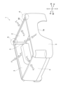
- FIG. 1 is a perspective view of a vehicle cargo box to which the vehicle cargo box reinforcing structure of the present invention can be applied.
- FIG. 2 is a perspective view of a vehicle cargo box to which the vehicle cargo box reinforcement structure of the present invention can be applied.
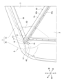
- FIG. 3 is a perspective view showing the periphery of the connecting and fixing portion between the header board and the side gate.
- FIG. 4 is an enlarged view of the main part of FIG. 3.
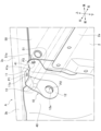
- FIG. 5 is a perspective view showing the periphery of the connecting and fixing portion between the header board and the side gate, with the header board 2 omitted.
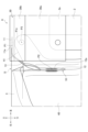
- FIG. 6 is a top view showing the periphery of the connecting and fixing portion between the header board and the side gate.
- FIG. 7 is an enlarged view of the main part of FIG. FIG.
- FIG. 8 is a rear view of the periphery of the connecting and fixing portion between the header board and the side gate.
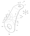
- FIG. 9 is a perspective view of the bracket.
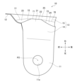
- FIG. 10 is a diagram of the bracket seen from the rear of the vehicle.
- FIG. 11 is a diagram of the bracket viewed from the vehicle width direction.
- FIG. 12 is a diagram of the bracket viewed from above the vehicle.
- FIG. 13 is a partially cutaway side view of the connecting and fixed portion viewed from the vehicle width direction.
- the directions of the vehicle longitudinal direction, the vehicle left-right direction (vehicle width direction), and the vehicle vertical direction, which are the directions seen from the driver (occupant) of the vehicle, are indicated by arrows.
- the orientations when attached to the vehicle are shown.
- the types of vehicles to which the vehicle cargo box reinforcement structure of the present embodiment is applied are not particularly limited, and include, for example, gasoline vehicles, electric vehicles (EV), hybrid vehicles (HEV), plug-in hybrid vehicles (PHEV), etc. Applicable to
- FIGS. 1 and 2 are perspective views of a vehicle cargo box 1 to which the vehicle cargo box reinforcing structure of the present invention can be applied.
- vehicle cargo boxes 1 in FIGS. 1 and 2 differ in detail, they have the same general configuration and are therefore given the same reference numerals.
- the vehicle cargo box 1 is placed behind the cabin of the vehicle.
- the vehicle cargo box 1 includes a front header board 2, a pair of left and right side gates 3, 3, a rear tailgate 4, and a lower floor panel 5.
- the header board 2 constitutes the front wall surface of the vehicle cargo box 1 and extends in the left-right direction (vehicle width direction).
- a pair of side gates 3, 3 are arranged across the header board 2. Specifically, the pair of side gates 3, 3 are connected to both left and right ends of the header board 2, extend mainly toward the rear of the vehicle, and constitute the left and right wall surfaces of the vehicle cargo box 1.
- a wheel arch 3a is formed at the lower end of each side gate 3.
- the tailgate 4 is connected to the rear end portions of the pair of side gates 3, 3, and extends in the left-right direction.
- the floor panel 5 closes the lower side of the space surrounded by the header board 2, the pair of side gates 3, and the tail gate 4.
- the vehicle cargo box 1 is a rectangular storage space when viewed from above, which is configured by the header board 2, the pair of side gates 3, 3, the tail gate 4, and the floor panel 5.
- An upper rail 30 is fixed to the top of the header board 2 along the vehicle width direction by welding or the like.
- a guard frame 60 is fixed to the upper part of the upper rail 30.
- the header board 2, the pair of side gates 3, and the tailgate 4 are attached to stand on the floor panel 5.
- the lower end of the tailgate 4 is rotatably provided with respect to the floor panel 5 as shown in FIG. 1, and is configured to facilitate loading and unloading of luggage into the vehicle cargo box 1.
- the cargo box An inward force F2 is applied from the outside toward the inside of the cargo box. Due to this inward force F2, a load is applied to the connecting portion between both ends of the header board 2 in the vehicle width direction and the inner surfaces in the vehicle width direction of the pair of side gates 3, 3 so as to close the connecting portion. be done.
- the header board 2 and the pair of side gates 3, 3 are connected and reinforced by a separate plate-shaped bracket 10 (fixing member). More specifically, the upper end portions of both ends in the vehicle width direction of the header board 2 and the pair of side gates 3 have connecting fixed portions A, A including a bracket 10 (see FIGS. 3 to 8), which will be described later. They are connected and reinforced through. Note that the bracket 10 is not shown in FIGS. 1 and 2.
- FIG. 3 is a perspective view showing the vicinity of the connecting and fixing portion A between the header board 2 and the side gate 3.
- FIG. 4 is an enlarged view of the main part of FIG. 3.
- FIG. 5 is a perspective view showing the periphery of a connecting and fixed portion A between the header board 2 and the side gate 3, with the header board 2 omitted.
- FIG. 6 is a top view showing the vicinity of the connecting and fixing portion A between the header board 2 and the side gate 3.
- FIG. 7 is an enlarged view of the main part of FIG.
- FIG. 8 is a view of the periphery of the connecting and fixing portion A between the header board 2 and the side gate 3, seen from the rear.
- the left and right connecting and fixing parts A, A between the header board 2 and the pair of side gates 3, 3 are symmetrical in the vehicle width direction. Therefore, in the following description, only the right side connecting and fixing portion A will be illustrated and explained.
- a bracket 10 is provided as a plate-shaped fixing member that connects the header board 2 and the side gate 3. Details of the bracket 10 will be described later.
- An upper rail 30 serving as a first reinforcing member having a bent cross-sectional shape is provided at the upper end 2a (upper part) of the header board 2 along the vehicle width direction.
- the upper rail 30 is fixed to the header board 2 by welding or the like.
- the upper rail 30 includes a base portion 30a that extends in the vertical direction along the front surface of the header board 2, and an extension portion 30b that extends forward from the upper end of the base portion 30a.
- the front end portion of the extension portion 30b has a hook shape bent downward and backward, and a rope or the like for securing cargo placed in the vehicle cargo box 1 can be fixed thereto.
- the upper rail 30 has a generally inverted L-shaped cross section.
- the side gate 3 as a whole is curved so as to bulge outward in the vehicle width direction, and has a front portion 3b located in front of the vehicle than the header board 2, and a rear portion 3b located in the rear of the vehicle than the header board 2. and a side portion 3c.
- a front reinforcement 40 as a second reinforcing member is fixed to the inner surface in the vehicle width direction of the front portion 3b as a predetermined location of the side gate 3.
- a rear reinforcement 50 serving as a third reinforcing member is fixed to the side gate 3 behind the header board 2 in the vehicle.
- the rear end portion of the front reinforcement 40 is located further rearward of the vehicle than the bracket 10 and furthermore slightly rearward of the vehicle than the upper rail 30.
- a projecting piece 41 extending inward in the vehicle width direction is formed at the upper end of the rear end of the front reinforcement 40.
- the protruding piece 41 has a flat plate shape that extends substantially perpendicularly to the vehicle longitudinal direction (substantially parallel to the vehicle vertical direction and vehicle width direction).
- the projecting piece 41 is arranged at substantially the same position as the header board 2 in the front and rear of the vehicle, and is arranged above the header board 2.
- the front surface of the projecting piece 41 contacts the rear surface of the base 30a of the upper rail 30.
- a projecting wall 51 that extends inward in the vehicle width direction is formed at the upper end of the front end of the rear reinforcement 50.
- the projecting wall 51 has a flat plate shape that extends substantially perpendicularly to the vehicle longitudinal direction (substantially parallel to the vehicle vertical direction and vehicle width direction). The front surface of the projecting wall 51 contacts the rear surface of the projecting piece 41.
- the projecting piece 41 of the front reinforcement 40 is sandwiched between the rear surface of the base 30a of the upper rail 30 and the front surface of the projecting wall 51 of the rear reinforcement 50 in the front-rear direction.
- the protrusion piece 41 is formed with a protrusion hole 41a that penetrates the protrusion piece 41 in the front-back direction
- the protrusion wall 51 is provided with a protrusion wall hole 51a that penetrates the protrusion wall 51 in the front-rear direction. ing.
- the fixing method at the third fixing point P3 is not limited to welding, and bolt fixing or the like may be employed.
- FIG. 9 is a perspective view of the bracket 10.
- FIG. 10 is a diagram of the bracket 10 seen from the rear of the vehicle.
- FIG. 11 is a diagram of the bracket 10 viewed from the vehicle width direction.
- FIG. 12 is a diagram of the bracket 10 viewed from above the vehicle.
- the bracket 10 includes a first fixing portion 11 provided on one side of the bracket 10 and fixed to the upper part of the header board 2, and a first fixing portion 11 on the other side of the bracket 10.
- a second fixed part 12 which is provided at a predetermined location of the side gate 3 located in front of the header board 2 in the vehicle; and a connecting part 13 which connects the first fixed part 11 and the second fixed part 12. It is a plate-shaped fixing member having .
- the first fixed portion 11 is located on the upper end side of the bracket 10 and extends substantially perpendicularly in the up-down direction (substantially parallel to the vehicle width direction and the front-rear direction).
- a through hole 11a extending in the vertical direction is formed approximately at the center of the first fixed portion 11.
- the upper surface of the first fixed portion 11 abuts on the upper surface of the header board 2, more specifically, on the lower surface of the extending portion 30b of the upper rail 30.
- the first fixed portion 11 is fixed to the lower surface of the extending portion 30b of the upper rail 30 through the through hole 11a by welding or the like.
- first fixed point P1 The point at which the first fixed portion 11 of the bracket 10 and the extension portion 30b of the upper rail 30 (the upper part of the header board 2) are fixed in this way is called a first fixed point P1.
- the fixing method at the first fixing point P1 is not limited to welding, and bolt fixing or the like may be employed.
- the second fixed portion 12 is located at the lower end side of the bracket 10 and extends substantially perpendicular to the vehicle width direction (substantially parallel to the vertical direction and the front-rear direction). Strictly speaking, the illustrated second fixed portion 12 is slightly inclined outward in the vehicle width direction toward the bottom, thereby enhancing the stress dispersion effect.
- a through hole 12a extending in the vehicle width direction is formed approximately at the center of the second fixed portion 12.
- the outer surface of the second fixed portion 12 in the vehicle width direction is located at a predetermined location of the side gate 3 located forward of the header board 2, more specifically, a front reinforcement 40 provided at the predetermined location of the side gate 3. It comes into contact with the inside surface in the vehicle width direction.
- the second fixed portion 12 is fixed to the inner surface of the front reinforcement 40 in the vehicle width direction by welding or the like via the through hole 12a.
- the point at which the second fixing portion 12 of the bracket 10 and the front reinforcement 40 as the second reinforcing member are fixed in this manner is referred to as a second fixing point P2.
- the fixing method at the second fixing point P2 is not limited to welding, and bolt fixing or the like may be employed.
- the connecting portion 13 is inclined in the vehicle vertical direction as it goes in the vehicle width direction between the first fixed portion 11 and the second fixed portion 12.
- the connecting portion 13 slopes downward as it goes outward in the vehicle width direction.
- the width of the connecting portion 13 in the front-rear direction increases as it goes downward. More specifically, the connecting portion 13 mainly bulges forward as it goes downward.
- the second fixed portion 12 that connects to the lower end of the connecting portion 13 bulges out further forward than the first fixed portion 11 as a whole.
- the second fixing point P2 formed by the through hole 12a provided approximately at the center of the second fixed portion 12 and the second fixing point P2 formed by the through hole 12a provided approximately at the center of the first fixed portion 11 is 11a is located below and in front of the first fixed point P1. That is, as shown in FIG. 11, the first fixed point P1 and the second fixed point P2 are offset by a distance L1 in the front-back direction and by a distance L2 in the vertical direction.
- the third fixing point P3 which is the point at which the upper rail 30, the front reinforcement 40, and the rear reinforcement 50 are fixed, is the first fixing point of the bracket 10 in the vehicle vertical direction. It is located between the portion 11 and the second fixed portion 12. Thereby, the third fixed point P3 is located between the first fixed point P1 and the second fixed point P2 in the vehicle vertical direction.
- the connecting portion 13 includes a first connecting portion 14 disposed above and a second connecting portion 15 disposed below.
- the first connecting part 14 connects to the first fixed part 11.
- the first connecting portion 14 has a substantially flat plate shape that slopes downward as it goes outward in the vehicle width direction from the first fixed portion 11 .
- the second connecting portion 15 connects the first connecting portion 14 and the second fixed portion 12 to each other. Like the first connecting portion 14, the second connecting portion 15 slopes downward as it goes outward in the vehicle width direction, but unlike the first connecting portion 14, the second connecting portion 15 has a A plurality of ridge lines 71 to 78 are formed by bending in the directions.
- the second connecting portion 15 includes a plurality of inclined portions 21 to 25 that are partitioned by a plurality of ridge lines 71 to 78 and inclined in approximately the same direction.
- the plurality of slopes 21 to 25 have multifaceted structures with different slope angles, slope directions, shapes, etc., and include a first slope 21, a second slope 22, a third slope 23, a fourth slope 24, and a fifth slope portion 25 .
- the first inclined portion 21 is located above the second connecting portion 15 and connects to the lower end of the first connecting portion 14 .
- the second inclined portion 22 is located at the center of the second connecting portion 15 .
- the third inclined part 23 is located in front of the second inclined part 22.
- the fourth inclined part 24 is located behind the second inclined part 22.
- the fifth inclined portion 25 is located at the lower part of the second connecting portion 15 and connects to the upper end of the second fixed portion 12 .
- the first ridgeline 71 extends substantially parallel to the vehicle longitudinal direction and partitions the first slope portion 21 and the second slope portion 22 .
- the second ridgeline 72 is connected to the first ridgeline 71 and extends upward and inward in the vehicle width direction as it goes forward.
- the second ridgeline 72 partitions the first slope portion 21 and the third slope portion 23.
- the third ridgeline 73 is connected to the first ridgeline 71 and extends upward and inward in the vehicle width direction toward the rear.
- the third ridgeline 73 partitions the first slope portion 21 and the fourth slope portion 24 .
- the fourth ridgeline 74 is connected to the first ridgeline 71 and the second ridgeline 72, and extends outward in the vehicle width direction as it goes downward.
- the fourth ridgeline 74 partitions the second slope portion 22 and the third slope portion 23.
- the fifth ridgeline 75 connects with the first ridgeline 71 and the third ridgeline 73, and extends outward in the vehicle width direction as it goes downward.
- the fifth ridgeline 75 is substantially parallel to the fourth ridgeline 74.
- the fifth ridgeline 75 partitions the second slope portion 22 and the fourth slope portion 24 .
- the sixth ridgeline 76 extends substantially parallel to the vehicle longitudinal direction and partitions the second slope portion 22 and the fifth slope portion 25 .
- the sixth ridgeline 76 is substantially parallel to the first ridgeline 71.
- the seventh ridgeline 77 is connected to the fourth ridgeline 74 and the sixth ridgeline 76, and extends downward and outward in the vehicle width direction as it goes forward.
- the seventh ridgeline 77 separates the third slope portion 23 and the fifth slope portion 25.
- the eighth ridgeline 78 is connected to the fifth ridgeline 75 and the sixth ridgeline 76, and extends downward and outward in the vehicle width direction toward the rear.
- the eighth ridgeline 78 separates the fourth slope portion 24 and the fifth slope portion 25.
- a second inclined portion 22 having a substantially rectangular shape in side view is arranged at the center, and first, third, fourth, and fifth inclined portions 21 having a substantially trapezoidal shape in side view are arranged around the second inclined portion 22. , 23, 24, and 25 are arranged.
- the second inclined part 22 at the center has a shape that projects most in the thickness direction (outside in the vehicle width direction) of the bracket 10. In this way, since the connecting portion 13 is provided with the bending structure consisting of the plurality of ridge lines 71 to 78, the rigidity of the bracket 10 can be increased.
- FIG. 13 is a partially cutaway side view of the fixed connection portion A when viewed from the vehicle width direction.
- a bracket 10 is provided to connect the header board 2 and the side gate 3 to reinforce the connection portion.
- the bracket 10 of this embodiment has a first fixed part 11 provided on one side of the bracket 10 and fixed to the upper part (upper rail 30) of the header board 2, and a first fixed part 11 provided on the other side of the bracket 10 and fixed to the header board 2.
- It has a second fixed portion 12 fixed to a predetermined location (front reinforcement 40) of the side gate 3 located further forward of the vehicle than the board 2. That is, the first fixed portion 11 and the second fixed portion 12 of the bracket 10 are offset in the vehicle longitudinal direction. Therefore, the first fixed portion 11 and the second fixed portion 12 can receive part of the external force as a shearing force, and the load on the bracket 10 can be reduced.
- the bracket 10 is located outside the storage area of the vehicle cargo box 1, and the storage capacity of the vehicle cargo box 1 can be increased. Furthermore, since the bracket 10 is plate-shaped, it can be made lighter.
- the bracket 10 has a connecting portion 13 that connects the first fixed portion 11 and the second fixed portion 12 and is inclined in the vehicle vertical direction as it goes in the vehicle width direction. Therefore, the load on the bracket 10 can be distributed. Note that, as shown by the broken line D in FIG. The load will be concentrated on the corner that connects the fixed part 11 and the second fixed part 12. In this case, it becomes necessary to increase the strength of the bracket 10 itself, and increasing the plate thickness or adding a bead shape causes an increase in weight and cost, which is not preferable.
- the first fixed portion 11 and the second fixed portion 12 connected at the connecting portion 13 are offset not only in the vehicle longitudinal direction but also in the vehicle vertical direction and vehicle width direction.
- the positional relationship between the first fixed point P1) and the second fixed part 12 (second fixed point P2) is three-dimensional. Therefore, the stress generated in the first fixed portion 11 (first fixed point P1) and the second fixed portion 12 (second fixed point P2) is easily dispersed in the longitudinal direction, the vertical direction, and the vehicle width direction. As a result, the stress dispersion function of the bracket 10 is further enhanced, and the deformation prevention effect can be enhanced.
- a first fixing point P1 where the first fixed part 11 of the bracket 10 and the upper part of the header board 2 (upper rail 30) are fixed, and a predetermined point P1 where the second fixed part 12 of the bracket 10 and the side gate 3 (front reinforcement) are fixed. 40) and the second fixed point P2 to which are fixed are offset in the longitudinal direction of the vehicle. Therefore, external force can be efficiently received.
- a force F3 that causes the extension portion 30b of the upper rail 30 to deform in a floating manner acts on it, the load on the bracket 10 can be reduced.
- first fixed point P1 and the second fixed point P2 are at the same position in the longitudinal direction of the vehicle, the line connecting the first fixed point P1 and the second fixed point P2 and the force F3 directed toward the rear of the vehicle and are vertical, making it difficult to receive the load efficiently.
- an upper rail 30 (first reinforcing member) having a bent cross-sectional shape is provided along the vehicle width direction, and the first fixed portion 11 of the bracket 10 is attached to the upper rail 30. Fixed. Therefore, the upper part of the header board 2, which tends to be a weak part, can be reinforced by the upper rail 30 in addition to the bracket 10.
- a front reinforcement 40 (second reinforcing member) is provided at a predetermined location of the side gate 3, and the second fixed portion 12 of the bracket 10 is fixed to the front reinforcement 40. Therefore, predetermined parts of the header board 2 that tend to be weak parts can be reinforced by the front reinforcement 40 in addition to the bracket 10.
- a rear reinforcement 50 (third reinforcing member) is provided on the side gate 3 at a position further rearward of the vehicle than the header board 2. Therefore, the side gate 3 can be further reinforced.
- the front reinforcement 40 has a projecting piece 41 extending inward in the vehicle width direction, and the projecting piece 41 is sandwiched between the upper rail 30 and the rear reinforcement 50. Therefore, the front reinforcement 40 In addition to being fixed to the upper rail 30 by the bracket 10, the bracket 10 is also fixed to the upper rail 30 and the rear reinforcement 50 by being sandwiched, so that the load on the bracket 10 can be distributed.
- the third fixing point P3 to which the protruding piece 41 of the front reinforcement 40 and the rear reinforcement 50 are fixed is the first fixing part 11 (first fixing point P1) and the second fixing part of the bracket 10 in the vehicle vertical direction. 12 (second fixed point P2). Therefore, the load can be distributed by fixing at three points, and the three fixing points P1, P2, and P3 are arranged compactly. These three fixed points P1, P2, and P3 are directly connected to the bracket 10 and the three reinforcing members (upper rail 30, front reinforcement 40, and rear reinforcement 50), so the connecting fixed portion A The overall rigidity can be increased.
- the three fixed points P1, P2, and P3 are three-dimensionally arranged offset in the longitudinal direction, vertical direction, and vehicle width direction, so that they can cope with external forces in all directions. This can enhance the dispersion function and improve the effect of suppressing deformation.
- the connecting portion 13 of the bracket 10 has ridgelines 71 to 78 formed by bending the bracket 10 in the thickness direction. This improves the rigidity of the bracket 10.
- the connecting portion 13 of the bracket 10 has a structure in which the first to fifth sloped portions 21 to 25 are provided, but the number of sloped portions is not limited to this.
- the angle of inclination, shape, etc. of each inclined portion are not limited to those shown in the drawings.
Landscapes
- Engineering & Computer Science (AREA)
- Chemical & Material Sciences (AREA)
- Combustion & Propulsion (AREA)
- Transportation (AREA)
- Mechanical Engineering (AREA)
- Body Structure For Vehicles (AREA)
Abstract
Description
(1) 車両荷箱における車両前方の壁面を構成するヘッダーボードと、
前記ヘッダーボードに交差して配置されるサイドゲートと、
前記ヘッダーボードと、前記サイドゲートと、を連結する板状の固定部材と、
を備える車両荷箱の補強構造であって、
前記固定部材は、
前記固定部材の一方側に設けられ、前記ヘッダーボードの上部に固定される第1固定部分と、
前記固定部材の他方側に設けられ、前記ヘッダーボードよりも車両前方に位置する前記サイドゲートの所定箇所に固定される第2固定部分と、
を有する、
車両荷箱の補強構造。
(2) (1)に記載の車両荷箱の補強構造であって、
前記固定部材は、第1固定部分と第2固定部分とを接続し、車幅方向に向かうにつれて車両上下方向に傾斜する接続部を有する、
車両荷箱の補強構造。
(3) (1)又は(2)に記載の車両荷箱の補強構造であって、
前記固定部材の前記第1固定部分と前記ヘッダーボードの前記上部とが固定される第1固定点と、前記固定部材の前記第2固定部分と前記サイドゲートの前記所定箇所とが固定される第2固定点とが、車両前後方向にオフセットしている、
車両荷箱の補強構造。
(4) (1)~(3)の何れか一項に記載の車両荷箱の補強構造であって、
前記ヘッダーボードの前記上部には、横断面形状が屈曲形状をなす第1補強部材が、車幅方向に沿って設けられ、
前記固定部材の前記第1固定部分は、前記第1補強部材に固定される、
車両荷箱の補強構造。
(5) (1)~(4)の何れか一項に記載の車両荷箱の補強構造であって、
前記サイドゲートの前記所定箇所には、第2補強部材が設けられ、
前記固定部材の前記第2固定部分は、前記第2補強部材に固定される、
車両荷箱の補強構造。
(6) (1)~(5)の何れか一項に記載の車両荷箱の補強構造であって、
前記サイドゲートには、前記ヘッダーボードよりも車両後方に、第3補強部材が設けられる、
車両荷箱の補強構造。
(7) (1)~(3)の何れか一項に記載の車両荷箱の補強構造であって、
前記ヘッダーボードの前記上部には、横断面形状が屈曲形状をなす第1補強部材が、車幅方向に沿って設けられ、
前記固定部材の前記第1固定部分は、前記第1補強部材に固定され、
前記サイドゲートの前記所定箇所には、第2補強部材が設けられ、
前記固定部材の前記第2固定部分は、前記第2補強部材に固定され、
前記サイドゲートには、前記ヘッダーボードよりも車両後方に、第3補強部材が設けられ、
前記第2補強部材は、車幅方向内側に延びる突片を有し、
前記突片は、前記第1補強部材と前記第3補強部材とで挟み込まれている、
車両荷箱の補強構造。
(8) (7)に記載の車両荷箱の補強構造であって、
前記第2補強部材の前記突片と前記第3補強部材とが固定される第3固定点は、車両上下方向において前記第1固定部分と前記第2固定部分との間に位置する、
車両荷箱の補強構造。
(9) (2)に記載の車両荷箱の補強構造であって、
前記接続部には、前記固定部材の厚み方向への屈曲による稜線が形成されている、
車両荷箱の補強構造。
一対のサイドゲート3,3は、ヘッダーボード2に交差して配置される。具体的には、一対のサイドゲート3,3は、ヘッダーボード2の左右両端部に接続され、主に車両後方に延びて、車両荷箱1の左右両側の壁面を構成する。それぞれのサイドゲート3の下端部には、ホイールアーチ3aが形成される。
テールゲート4は、一対のサイドゲート3,3の後方端部に接続され、左右方向に延びる。
フロアパネル5は、ヘッダーボード2と、一対のサイドゲート3,3と、テールゲート4と、で囲まれた空間の下方側を閉じる。
第2傾斜部22は、第2接続部15の中央に位置する。
第3傾斜部23は、第2傾斜部22の前方に位置する。
第4傾斜部24は、第2傾斜部22の後方に位置する。
第5傾斜部25は、第2接続部15の下部に位置し、第2固定部分12の上端と接続する。
第2稜線72は、第1稜線71と接続し、前方に向かうにしたがって上方且つ車幅方向内側に延びる。第2稜線72は、第1傾斜部21と第3傾斜部23とを区画する。
第3稜線73は、第1稜線71と接続し、後方に向かうにしたがって上方且つ車幅方向内側に延びる。第3稜線73は、第1傾斜部21と第4傾斜部24とを区画する。
第4稜線74は、第1稜線71及び第2稜線72と接続し、下方に向かうにしたがって車幅方向外側に延びる。第4稜線74は、第2傾斜部22と第3傾斜部23とを区画する。
第5稜線75は、第1稜線71及び第3稜線73と接続し、下方に向かうにしたがって車幅方向外側に延びる。第5稜線75は、第4稜線74と略平行である。第5稜線75は、第2傾斜部22と第4傾斜部24とを区画する。
第6稜線76は、車両前後方向に略平行に延び、第2傾斜部22と第5傾斜部25とを区画する。第6稜線76は、第1稜線71と略平行である。
第7稜線77は、第4稜線74及び第6稜線76と接続し、前方に向かうにしたがって下方且つ車幅方向外側に延びる。第7稜線77は、第3傾斜部23と第5傾斜部25とを区画する。
第8稜線78は、第5稜線75及び第6稜線76と接続し、後方に向かうにしたがって下方且つ車幅方向外側に延びる。第8稜線78は、第4傾斜部24と第5傾斜部25とを区画する。
特に、本実施形態のブラケット10は、ブラケット10の一方側に設けられ、ヘッダーボード2の上部(アッパーレール30)に固定される第1固定部分11と、ブラケット10の他方側に設けられ、ヘッダーボード2よりも車両前方に位置するサイドゲート3の所定箇所(前側リンフォース40)に固定される第2固定部分12と、を有する。すなわち、ブラケット10の第1固定部分11と第2固定部分12とが車両前後方向にオフセットしている。したがって、第1固定部分11及び第2固定部分12において、外力の一部を剪断力として受けることができ、ブラケット10への負荷を軽減することができる。
また、第2固定部分12がヘッダーボード2よりも車両前方に位置するので、ブラケット10は車両荷箱1の収容領域外に位置され、車両荷箱1の収容容積を大きくできる。
また、ブラケット10が板状であることで、軽量化ができる。
また、接続部13で接続された第1固定部分11と第2固定部分12は、車両前後方向のオフセットに加え、車両上下方向及び車幅方向にもオフセットするので、第1固定部分11(第1固定点P1)と第2固定部分12(第2固定点P2)との位置関係が三次元となる。したがって、第1固定部分11(第1固定点P1)と第2固定部分12(第2固定点P2)に生じる応力は、前後方向、上下方向、車幅方向に分散し易くなる。この結果、ブラケット10の応力分散の機能がより高まり、変形防止効果を高めることができる。
特に、図13で示したように、アッパーレール30の延在部30bに浮き上がるような変形を生じさせる力F3が作用する場合に、ブラケット10への負荷を軽減することができる。仮に、第1固定点P1と第2固定点P2とが、車両前後方向に同一位置である場合、第1固定点P1と第2固定点P2とを結んだ線と、車両後方に向かう力F3と、が垂直になってしまい、効率良く負荷を受けることが困難である。
2 ヘッダーボード
2a 上端部
3 サイドゲート
3a ホイールアーチ
3b 前側部分
4 テールゲート
5 フロアパネル
10 ブラケット(固定部材)
11 第1固定部分
11a 貫通孔
12 第2固定部分
12a 貫通孔
13 接続部
14 第1接続部
15 第2接続部
21 第1傾斜部
22 第2傾斜部
23 第3傾斜部
24 第4傾斜部
25 第5傾斜部
30 アッパーレール(第1補強部材)
30a 基部
30b 延在部
40 前側リンフォース(第2補強部材)
41 突片
41a 突片孔
50 後側リンフォース(第3補強部材)
51 突壁
51a 突壁孔
60 ガードフレーム
71 第1稜線
72 第2稜線
73 第3稜線
74 第4稜線
75 第5稜線
76 第6稜線
77 第7稜線
78 第8稜線
A 連結固定部分
F1 外向きの力
F2 内向きの力
P1 第1固定点
P2 第2固定点
P3 第3固定点
Claims (9)
- 車両荷箱における車両前方の壁面を構成するヘッダーボードと、
前記ヘッダーボードに交差して配置されるサイドゲートと、
前記ヘッダーボードと、前記サイドゲートと、を連結する板状の固定部材と、
を備える車両荷箱の補強構造であって、
前記固定部材は、
前記固定部材の一方側に設けられ、前記ヘッダーボードの上部に固定される第1固定部分と、
前記固定部材の他方側に設けられ、前記ヘッダーボードよりも車両前方に位置する前記サイドゲートの所定箇所に固定される第2固定部分と、
を有する、
車両荷箱の補強構造。 - 請求項1に記載の車両荷箱の補強構造であって、
前記固定部材は、第1固定部分と第2固定部分とを接続し、車幅方向に向かうにつれて車両上下方向に傾斜する接続部を有する、
車両荷箱の補強構造。 - 請求項1又は2に記載の車両荷箱の補強構造であって、
前記固定部材の前記第1固定部分と前記ヘッダーボードの前記上部とが固定される第1固定点と、前記固定部材の前記第2固定部分と前記サイドゲートの前記所定箇所とが固定される第2固定点とが、車両前後方向にオフセットしている、
車両荷箱の補強構造。 - 請求項1~3の何れか一項に記載の車両荷箱の補強構造であって、
前記ヘッダーボードの前記上部には、横断面形状が屈曲形状をなす第1補強部材が、車幅方向に沿って設けられ、
前記固定部材の前記第1固定部分は、前記第1補強部材に固定される、
車両荷箱の補強構造。 - 請求項1~4の何れか一項に記載の車両荷箱の補強構造であって、
前記サイドゲートの前記所定箇所には、第2補強部材が設けられ、
前記固定部材の前記第2固定部分は、前記第2補強部材に固定される、
車両荷箱の補強構造。 - 請求項1~5の何れか一項に記載の車両荷箱の補強構造であって、
前記サイドゲートには、前記ヘッダーボードよりも車両後方に、第3補強部材が設けられる、
車両荷箱の補強構造。 - 請求項1~3の何れか一項に記載の車両荷箱の補強構造であって、
前記ヘッダーボードの前記上部には、横断面形状が屈曲形状をなす第1補強部材が、車幅方向に沿って設けられ、
前記固定部材の前記第1固定部分は、前記第1補強部材に固定され、
前記サイドゲートの前記所定箇所には、第2補強部材が設けられ、
前記固定部材の前記第2固定部分は、前記第2補強部材に固定され、
前記サイドゲートには、前記ヘッダーボードよりも車両後方に、第3補強部材が設けられ、
前記第2補強部材は、車幅方向内側に延びる突片を有し、
前記突片は、前記第1補強部材と前記第3補強部材とで挟み込まれている、
車両荷箱の補強構造。 - 請求項7に記載の車両荷箱の補強構造であって、
前記第2補強部材の前記突片と前記第3補強部材とが固定される第3固定点は、車両上下方向において前記第1固定部分と前記第2固定部分との間に位置する、
車両荷箱の補強構造。 - 請求項2に記載の車両荷箱の補強構造であって、
前記接続部には、前記固定部材の厚み方向への屈曲による稜線が形成されている、
車両荷箱の補強構造。
Priority Applications (2)
| Application Number | Priority Date | Filing Date | Title |
|---|---|---|---|
| PCT/JP2022/011361 WO2023175679A1 (ja) | 2022-03-14 | 2022-03-14 | 車両荷箱の補強構造 |
| JP2022579073A JP7235191B1 (ja) | 2022-03-14 | 2022-03-14 | 車両荷箱の補強構造 |
Applications Claiming Priority (1)
| Application Number | Priority Date | Filing Date | Title |
|---|---|---|---|
| PCT/JP2022/011361 WO2023175679A1 (ja) | 2022-03-14 | 2022-03-14 | 車両荷箱の補強構造 |
Publications (1)
| Publication Number | Publication Date |
|---|---|
| WO2023175679A1 true WO2023175679A1 (ja) | 2023-09-21 |
Family
ID=85475695
Family Applications (1)
| Application Number | Title | Priority Date | Filing Date |
|---|---|---|---|
| PCT/JP2022/011361 Ceased WO2023175679A1 (ja) | 2022-03-14 | 2022-03-14 | 車両荷箱の補強構造 |
Country Status (2)
| Country | Link |
|---|---|
| JP (1) | JP7235191B1 (ja) |
| WO (1) | WO2023175679A1 (ja) |
Citations (5)
| Publication number | Priority date | Publication date | Assignee | Title |
|---|---|---|---|---|
| JPS5417215Y2 (ja) * | 1976-11-08 | 1979-07-04 | ||
| JPS624063Y2 (ja) * | 1980-03-03 | 1987-01-29 | ||
| JPS6342697Y2 (ja) * | 1983-10-19 | 1988-11-08 | ||
| JP2000255461A (ja) * | 1999-03-11 | 2000-09-19 | Hino Motors Ltd | 荷台外板の補強構造 |
| JP2006137426A (ja) * | 2004-11-12 | 2006-06-01 | Honda Motor Co Ltd | キャブと荷物運搬ベッド間の車両フレームの壁構造物 |
-
2022
- 2022-03-14 JP JP2022579073A patent/JP7235191B1/ja active Active
- 2022-03-14 WO PCT/JP2022/011361 patent/WO2023175679A1/ja not_active Ceased
Patent Citations (5)
| Publication number | Priority date | Publication date | Assignee | Title |
|---|---|---|---|---|
| JPS5417215Y2 (ja) * | 1976-11-08 | 1979-07-04 | ||
| JPS624063Y2 (ja) * | 1980-03-03 | 1987-01-29 | ||
| JPS6342697Y2 (ja) * | 1983-10-19 | 1988-11-08 | ||
| JP2000255461A (ja) * | 1999-03-11 | 2000-09-19 | Hino Motors Ltd | 荷台外板の補強構造 |
| JP2006137426A (ja) * | 2004-11-12 | 2006-06-01 | Honda Motor Co Ltd | キャブと荷物運搬ベッド間の車両フレームの壁構造物 |
Also Published As
| Publication number | Publication date |
|---|---|
| JPWO2023175679A1 (ja) | 2023-09-21 |
| JP7235191B1 (ja) | 2023-03-08 |
Similar Documents
| Publication | Publication Date | Title |
|---|---|---|
| KR102910901B1 (ko) | 차체구조물 | |
| CN102205857B (zh) | 汽车的车身构造 | |
| CN103717481A (zh) | 车体侧部构造 | |
| CN108791508A (zh) | 车辆下部结构 | |
| US20080277971A1 (en) | Vehicle deck structure | |
| EP2412612B1 (en) | Side sill structure for automobile | |
| JP2007022485A (ja) | 車体側部構造 | |
| US12194828B2 (en) | Vehicle body lower section structure | |
| JP2021169272A (ja) | 車体下部構造 | |
| JP7235191B1 (ja) | 車両荷箱の補強構造 | |
| JP2021160511A (ja) | 電動車両の下部構造 | |
| JP7711836B2 (ja) | 車両荷箱構造 | |
| JP3818432B2 (ja) | 自動車の車体フロアへのシートベルト連結装置 | |
| JP4083078B2 (ja) | 自動車の車体前部構造 | |
| JP6070602B2 (ja) | 車両の車体下部構造 | |
| JP4304449B2 (ja) | 車両の前部車体構造 | |
| JP7329198B2 (ja) | 車両のフロア構造 | |
| KR102703585B1 (ko) | 차체구조물 및 이를 포함하는 차량 | |
| JP7348601B1 (ja) | 車両の後部構造 | |
| JP2026057008A (ja) | 車両の下部車体構造 | |
| JP2003252251A (ja) | 車体のフロア構造 | |
| JP4204362B2 (ja) | キャブの変形防止構造 | |
| JP2010215196A (ja) | 自動車の車体構造 | |
| JP7015476B2 (ja) | ルーフパネル及びルーフ構造 | |
| WO2024201847A1 (ja) | 車両の荷箱構造 |
Legal Events
| Date | Code | Title | Description |
|---|---|---|---|
| WWE | Wipo information: entry into national phase |
Ref document number: 2022579073 Country of ref document: JP |
|
| 121 | Ep: the epo has been informed by wipo that ep was designated in this application |
Ref document number: 22931964 Country of ref document: EP Kind code of ref document: A1 |
|
| REG | Reference to national code |
Ref country code: BR Ref legal event code: B01A Ref document number: 112023004029 Country of ref document: BR |
|
| NENP | Non-entry into the national phase |
Ref country code: DE |
|
| ENP | Entry into the national phase |
Ref document number: 112023004029 Country of ref document: BR Kind code of ref document: A2 Effective date: 20230303 |
|
| 122 | Ep: pct application non-entry in european phase |
Ref document number: 22931964 Country of ref document: EP Kind code of ref document: A1 |