WO2023171818A1 - 熱伝達抑制シートの製造方法、熱伝達抑制シート及び組電池 - Google Patents
熱伝達抑制シートの製造方法、熱伝達抑制シート及び組電池 Download PDFInfo
- Publication number
- WO2023171818A1 WO2023171818A1 PCT/JP2023/009465 JP2023009465W WO2023171818A1 WO 2023171818 A1 WO2023171818 A1 WO 2023171818A1 JP 2023009465 W JP2023009465 W JP 2023009465W WO 2023171818 A1 WO2023171818 A1 WO 2023171818A1
- Authority
- WO
- WIPO (PCT)
- Prior art keywords
- heat transfer
- organic material
- melting point
- particles
- transfer suppressing
- Prior art date
Links
- 238000012546 transfer Methods 0.000 title claims abstract description 199
- 238000004519 manufacturing process Methods 0.000 title claims abstract description 60
- 230000001629 suppression Effects 0.000 title claims abstract description 32
- 239000010954 inorganic particle Substances 0.000 claims abstract description 161
- 239000000835 fiber Substances 0.000 claims abstract description 145
- 238000002844 melting Methods 0.000 claims abstract description 121
- 230000008018 melting Effects 0.000 claims abstract description 121
- 239000011368 organic material Substances 0.000 claims abstract description 111
- 238000000034 method Methods 0.000 claims abstract description 77
- 239000011230 binding agent Substances 0.000 claims abstract description 66
- 239000000203 mixture Substances 0.000 claims abstract description 42
- 238000012545 processing Methods 0.000 claims abstract description 13
- 230000002093 peripheral effect Effects 0.000 claims abstract description 12
- VYPSYNLAJGMNEJ-UHFFFAOYSA-N Silicium dioxide Chemical compound O=[Si]=O VYPSYNLAJGMNEJ-UHFFFAOYSA-N 0.000 claims description 124
- 239000002245 particle Substances 0.000 claims description 90
- 239000000843 powder Substances 0.000 claims description 86
- 239000012943 hotmelt Substances 0.000 claims description 58
- 238000010438 heat treatment Methods 0.000 claims description 56
- GWEVSGVZZGPLCZ-UHFFFAOYSA-N Titan oxide Chemical compound O=[Ti]=O GWEVSGVZZGPLCZ-UHFFFAOYSA-N 0.000 claims description 52
- -1 polyethylene terephthalate Polymers 0.000 claims description 46
- 229920000139 polyethylene terephthalate Polymers 0.000 claims description 27
- 239000005020 polyethylene terephthalate Substances 0.000 claims description 27
- XLOMVQKBTHCTTD-UHFFFAOYSA-N Zinc monoxide Chemical compound [Zn]=O XLOMVQKBTHCTTD-UHFFFAOYSA-N 0.000 claims description 14
- MCMNRKCIXSYSNV-UHFFFAOYSA-N Zirconium dioxide Chemical compound O=[Zr]=O MCMNRKCIXSYSNV-UHFFFAOYSA-N 0.000 claims description 12
- 239000004743 Polypropylene Substances 0.000 claims description 11
- 229920001155 polypropylene Polymers 0.000 claims description 11
- 239000004698 Polyethylene Substances 0.000 claims description 10
- 229920000573 polyethylene Polymers 0.000 claims description 10
- 239000004677 Nylon Substances 0.000 claims description 9
- 229920001778 nylon Polymers 0.000 claims description 9
- PNEYBMLMFCGWSK-UHFFFAOYSA-N aluminium oxide Inorganic materials [O-2].[O-2].[O-2].[Al+3].[Al+3] PNEYBMLMFCGWSK-UHFFFAOYSA-N 0.000 claims description 7
- 229910010272 inorganic material Inorganic materials 0.000 claims description 7
- 239000011147 inorganic material Substances 0.000 claims description 7
- 239000011787 zinc oxide Substances 0.000 claims description 7
- 229910052845 zircon Inorganic materials 0.000 claims description 7
- GFQYVLUOOAAOGM-UHFFFAOYSA-N zirconium(iv) silicate Chemical compound [Zr+4].[O-][Si]([O-])([O-])[O-] GFQYVLUOOAAOGM-UHFFFAOYSA-N 0.000 claims description 7
- 239000004965 Silica aerogel Substances 0.000 claims description 6
- HBMJWWWQQXIZIP-UHFFFAOYSA-N silicon carbide Chemical compound [Si+]#[C-] HBMJWWWQQXIZIP-UHFFFAOYSA-N 0.000 claims description 5
- 229910010271 silicon carbide Inorganic materials 0.000 claims description 5
- 150000004767 nitrides Chemical class 0.000 claims description 4
- 230000005540 biological transmission Effects 0.000 claims description 2
- 238000009413 insulation Methods 0.000 abstract description 43
- 239000000463 material Substances 0.000 description 59
- 239000000377 silicon dioxide Substances 0.000 description 54
- 238000012360 testing method Methods 0.000 description 33
- 239000002105 nanoparticle Substances 0.000 description 32
- 239000011164 primary particle Substances 0.000 description 29
- 230000000052 comparative effect Effects 0.000 description 20
- 230000000694 effects Effects 0.000 description 15
- XLYOFNOQVPJJNP-UHFFFAOYSA-N water Substances O XLYOFNOQVPJJNP-UHFFFAOYSA-N 0.000 description 15
- 238000010586 diagram Methods 0.000 description 13
- 238000001816 cooling Methods 0.000 description 10
- 229910044991 metal oxide Inorganic materials 0.000 description 10
- 150000004706 metal oxides Chemical class 0.000 description 10
- 230000001070 adhesive effect Effects 0.000 description 8
- 239000000853 adhesive Substances 0.000 description 7
- 230000002829 reductive effect Effects 0.000 description 7
- 238000011156 evaluation Methods 0.000 description 5
- 239000003365 glass fiber Substances 0.000 description 5
- 239000011810 insulating material Substances 0.000 description 5
- 239000011148 porous material Substances 0.000 description 5
- 230000008569 process Effects 0.000 description 5
- 238000007599 discharging Methods 0.000 description 4
- 239000002994 raw material Substances 0.000 description 4
- 239000011163 secondary particle Substances 0.000 description 4
- 238000005979 thermal decomposition reaction Methods 0.000 description 4
- RNFJDJUURJAICM-UHFFFAOYSA-N 2,2,4,4,6,6-hexaphenoxy-1,3,5-triaza-2$l^{5},4$l^{5},6$l^{5}-triphosphacyclohexa-1,3,5-triene Chemical compound N=1P(OC=2C=CC=CC=2)(OC=2C=CC=CC=2)=NP(OC=2C=CC=CC=2)(OC=2C=CC=CC=2)=NP=1(OC=1C=CC=CC=1)OC1=CC=CC=C1 RNFJDJUURJAICM-UHFFFAOYSA-N 0.000 description 3
- 239000004952 Polyamide Substances 0.000 description 3
- 230000000903 blocking effect Effects 0.000 description 3
- 230000008859 change Effects 0.000 description 3
- 239000011248 coating agent Substances 0.000 description 3
- 238000000576 coating method Methods 0.000 description 3
- 238000002425 crystallisation Methods 0.000 description 3
- 230000008025 crystallization Effects 0.000 description 3
- 239000005038 ethylene vinyl acetate Substances 0.000 description 3
- 239000003063 flame retardant Substances 0.000 description 3
- 150000004677 hydrates Chemical class 0.000 description 3
- 238000005259 measurement Methods 0.000 description 3
- 238000000465 moulding Methods 0.000 description 3
- 239000011242 organic-inorganic particle Substances 0.000 description 3
- 229920002647 polyamide Polymers 0.000 description 3
- 238000002360 preparation method Methods 0.000 description 3
- 230000000717 retained effect Effects 0.000 description 3
- 239000002904 solvent Substances 0.000 description 3
- IVORCBKUUYGUOL-UHFFFAOYSA-N 1-ethynyl-2,4-dimethoxybenzene Chemical compound COC1=CC=C(C#C)C(OC)=C1 IVORCBKUUYGUOL-UHFFFAOYSA-N 0.000 description 2
- 229910018072 Al 2 O 3 Inorganic materials 0.000 description 2
- 239000002253 acid Substances 0.000 description 2
- 230000009471 action Effects 0.000 description 2
- WNROFYMDJYEPJX-UHFFFAOYSA-K aluminium hydroxide Chemical compound [OH-].[OH-].[OH-].[Al+3] WNROFYMDJYEPJX-UHFFFAOYSA-K 0.000 description 2
- 229910002113 barium titanate Inorganic materials 0.000 description 2
- JRPBQTZRNDNNOP-UHFFFAOYSA-N barium titanate Chemical compound [Ba+2].[Ba+2].[O-][Ti]([O-])([O-])[O-] JRPBQTZRNDNNOP-UHFFFAOYSA-N 0.000 description 2
- DQXBYHZEEUGOBF-UHFFFAOYSA-N but-3-enoic acid;ethene Chemical compound C=C.OC(=O)CC=C DQXBYHZEEUGOBF-UHFFFAOYSA-N 0.000 description 2
- AXCZMVOFGPJBDE-UHFFFAOYSA-L calcium dihydroxide Chemical compound [OH-].[OH-].[Ca+2] AXCZMVOFGPJBDE-UHFFFAOYSA-L 0.000 description 2
- 239000013078 crystal Substances 0.000 description 2
- 230000007423 decrease Effects 0.000 description 2
- DNUARHPNFXVKEI-UHFFFAOYSA-K gallium(iii) hydroxide Chemical compound [OH-].[OH-].[OH-].[Ga+3] DNUARHPNFXVKEI-UHFFFAOYSA-K 0.000 description 2
- 239000011874 heated mixture Substances 0.000 description 2
- 230000000670 limiting effect Effects 0.000 description 2
- VTHJTEIRLNZDEV-UHFFFAOYSA-L magnesium dihydroxide Chemical compound [OH-].[OH-].[Mg+2] VTHJTEIRLNZDEV-UHFFFAOYSA-L 0.000 description 2
- 239000000347 magnesium hydroxide Substances 0.000 description 2
- 229910001862 magnesium hydroxide Inorganic materials 0.000 description 2
- 239000010445 mica Substances 0.000 description 2
- 229910052618 mica group Inorganic materials 0.000 description 2
- 238000002156 mixing Methods 0.000 description 2
- 229920001200 poly(ethylene-vinyl acetate) Polymers 0.000 description 2
- 229920000728 polyester Polymers 0.000 description 2
- 230000003014 reinforcing effect Effects 0.000 description 2
- OGIDPMRJRNCKJF-UHFFFAOYSA-N titanium oxide Inorganic materials [Ti]=O OGIDPMRJRNCKJF-UHFFFAOYSA-N 0.000 description 2
- 239000010455 vermiculite Substances 0.000 description 2
- 229910052902 vermiculite Inorganic materials 0.000 description 2
- 235000019354 vermiculite Nutrition 0.000 description 2
- 238000003466 welding Methods 0.000 description 2
- UGZADUVQMDAIAO-UHFFFAOYSA-L zinc hydroxide Chemical compound [OH-].[OH-].[Zn+2] UGZADUVQMDAIAO-UHFFFAOYSA-L 0.000 description 2
- 229910021511 zinc hydroxide Inorganic materials 0.000 description 2
- 229940007718 zinc hydroxide Drugs 0.000 description 2
- XWUCFAJNVTZRLE-UHFFFAOYSA-N 7-thiabicyclo[2.2.1]hepta-1,3,5-triene Chemical compound C1=C(S2)C=CC2=C1 XWUCFAJNVTZRLE-UHFFFAOYSA-N 0.000 description 1
- 239000005909 Kieselgur Substances 0.000 description 1
- HBBGRARXTFLTSG-UHFFFAOYSA-N Lithium ion Chemical compound [Li+] HBBGRARXTFLTSG-UHFFFAOYSA-N 0.000 description 1
- 229910019440 Mg(OH) Inorganic materials 0.000 description 1
- MXRIRQGCELJRSN-UHFFFAOYSA-N O.O.O.[Al] Chemical compound O.O.O.[Al] MXRIRQGCELJRSN-UHFFFAOYSA-N 0.000 description 1
- 239000004962 Polyamide-imide Substances 0.000 description 1
- 239000004695 Polyether sulfone Substances 0.000 description 1
- 239000004697 Polyetherimide Substances 0.000 description 1
- 239000004642 Polyimide Substances 0.000 description 1
- 239000004793 Polystyrene Substances 0.000 description 1
- BZHJMEDXRYGGRV-UHFFFAOYSA-N Vinyl chloride Chemical compound ClC=C BZHJMEDXRYGGRV-UHFFFAOYSA-N 0.000 description 1
- 229910021536 Zeolite Inorganic materials 0.000 description 1
- 230000002159 abnormal effect Effects 0.000 description 1
- 239000004964 aerogel Substances 0.000 description 1
- TZCXTZWJZNENPQ-UHFFFAOYSA-L barium sulfate Chemical compound [Ba+2].[O-]S([O-])(=O)=O TZCXTZWJZNENPQ-UHFFFAOYSA-L 0.000 description 1
- 239000010428 baryte Substances 0.000 description 1
- 229910052601 baryte Inorganic materials 0.000 description 1
- 239000000440 bentonite Substances 0.000 description 1
- 229910000278 bentonite Inorganic materials 0.000 description 1
- SVPXDRXYRYOSEX-UHFFFAOYSA-N bentoquatam Chemical compound O.O=[Si]=O.O=[Al]O[Al]=O SVPXDRXYRYOSEX-UHFFFAOYSA-N 0.000 description 1
- 239000000920 calcium hydroxide Substances 0.000 description 1
- 229910001861 calcium hydroxide Inorganic materials 0.000 description 1
- 238000006243 chemical reaction Methods 0.000 description 1
- 239000004927 clay Substances 0.000 description 1
- 230000006835 compression Effects 0.000 description 1
- 238000007906 compression Methods 0.000 description 1
- 239000000470 constituent Substances 0.000 description 1
- 230000008602 contraction Effects 0.000 description 1
- 229920003020 cross-linked polyethylene Polymers 0.000 description 1
- 239000004703 cross-linked polyethylene Substances 0.000 description 1
- 230000003247 decreasing effect Effects 0.000 description 1
- 238000011161 development Methods 0.000 description 1
- GUJOJGAPFQRJSV-UHFFFAOYSA-N dialuminum;dioxosilane;oxygen(2-);hydrate Chemical compound O.[O-2].[O-2].[O-2].[Al+3].[Al+3].O=[Si]=O.O=[Si]=O.O=[Si]=O.O=[Si]=O GUJOJGAPFQRJSV-UHFFFAOYSA-N 0.000 description 1
- HNPSIPDUKPIQMN-UHFFFAOYSA-N dioxosilane;oxo(oxoalumanyloxy)alumane Chemical compound O=[Si]=O.O=[Al]O[Al]=O HNPSIPDUKPIQMN-UHFFFAOYSA-N 0.000 description 1
- 239000006185 dispersion Substances 0.000 description 1
- 230000005611 electricity Effects 0.000 description 1
- 230000007613 environmental effect Effects 0.000 description 1
- 229920000840 ethylene tetrafluoroethylene copolymer Polymers 0.000 description 1
- 239000010881 fly ash Substances 0.000 description 1
- 229910021513 gallium hydroxide Inorganic materials 0.000 description 1
- 239000011521 glass Substances 0.000 description 1
- 230000020169 heat generation Effects 0.000 description 1
- 229920006015 heat resistant resin Polymers 0.000 description 1
- 238000007602 hot air drying Methods 0.000 description 1
- 239000004615 ingredient Substances 0.000 description 1
- 230000000977 initiatory effect Effects 0.000 description 1
- 239000012784 inorganic fiber Substances 0.000 description 1
- 239000012774 insulation material Substances 0.000 description 1
- 239000012212 insulator Substances 0.000 description 1
- 235000014413 iron hydroxide Nutrition 0.000 description 1
- NCNCGGDMXMBVIA-UHFFFAOYSA-L iron(ii) hydroxide Chemical compound [OH-].[OH-].[Fe+2] NCNCGGDMXMBVIA-UHFFFAOYSA-L 0.000 description 1
- HDMKAUUMGFGBRJ-UHFFFAOYSA-N iron;dihydrate Chemical compound O.O.[Fe] HDMKAUUMGFGBRJ-UHFFFAOYSA-N 0.000 description 1
- 230000001788 irregular Effects 0.000 description 1
- NLYAJNPCOHFWQQ-UHFFFAOYSA-N kaolin Chemical compound O.O.O=[Al]O[Si](=O)O[Si](=O)O[Al]=O NLYAJNPCOHFWQQ-UHFFFAOYSA-N 0.000 description 1
- 229910052622 kaolinite Inorganic materials 0.000 description 1
- 229910001416 lithium ion Inorganic materials 0.000 description 1
- 230000014759 maintenance of location Effects 0.000 description 1
- IPJKJLXEVHOKSE-UHFFFAOYSA-L manganese dihydroxide Chemical compound [OH-].[OH-].[Mn+2] IPJKJLXEVHOKSE-UHFFFAOYSA-L 0.000 description 1
- PMQJYWORJJEMQC-UHFFFAOYSA-N manganese;dihydrate Chemical compound O.O.[Mn] PMQJYWORJJEMQC-UHFFFAOYSA-N 0.000 description 1
- 230000007246 mechanism Effects 0.000 description 1
- 229910052987 metal hydride Inorganic materials 0.000 description 1
- 238000012986 modification Methods 0.000 description 1
- 230000004048 modification Effects 0.000 description 1
- 229910052901 montmorillonite Inorganic materials 0.000 description 1
- TWNQGVIAIRXVLR-UHFFFAOYSA-N oxo(oxoalumanyloxy)alumane Chemical compound O=[Al]O[Al]=O TWNQGVIAIRXVLR-UHFFFAOYSA-N 0.000 description 1
- RVTZCBVAJQQJTK-UHFFFAOYSA-N oxygen(2-);zirconium(4+) Chemical compound [O-2].[O-2].[Zr+4] RVTZCBVAJQQJTK-UHFFFAOYSA-N 0.000 description 1
- 229910001562 pearlite Inorganic materials 0.000 description 1
- 229920009441 perflouroethylene propylene Polymers 0.000 description 1
- 229920011301 perfluoro alkoxyl alkane Polymers 0.000 description 1
- 229920001084 poly(chloroprene) Polymers 0.000 description 1
- 229920002239 polyacrylonitrile Polymers 0.000 description 1
- 229920002312 polyamide-imide Polymers 0.000 description 1
- 229920001707 polybutylene terephthalate Polymers 0.000 description 1
- 239000004417 polycarbonate Substances 0.000 description 1
- 229920000515 polycarbonate Polymers 0.000 description 1
- 229920006393 polyether sulfone Polymers 0.000 description 1
- 229920001601 polyetherimide Polymers 0.000 description 1
- 229920001721 polyimide Polymers 0.000 description 1
- 229920006254 polymer film Polymers 0.000 description 1
- 229920002223 polystyrene Polymers 0.000 description 1
- 229920001343 polytetrafluoroethylene Polymers 0.000 description 1
- 239000004810 polytetrafluoroethylene Substances 0.000 description 1
- 238000003825 pressing Methods 0.000 description 1
- 230000005855 radiation Effects 0.000 description 1
- 229920005989 resin Polymers 0.000 description 1
- 239000011347 resin Substances 0.000 description 1
- 230000035939 shock Effects 0.000 description 1
- 229910052814 silicon oxide Inorganic materials 0.000 description 1
- 239000002002 slurry Substances 0.000 description 1
- 230000007480 spreading Effects 0.000 description 1
- 238000003892 spreading Methods 0.000 description 1
- 230000003068 static effect Effects 0.000 description 1
- 239000010457 zeolite Substances 0.000 description 1
- 239000011701 zinc Substances 0.000 description 1
- 229910001928 zirconium oxide Inorganic materials 0.000 description 1
Images


Classifications
-
- B—PERFORMING OPERATIONS; TRANSPORTING
- B29—WORKING OF PLASTICS; WORKING OF SUBSTANCES IN A PLASTIC STATE IN GENERAL
- B29C—SHAPING OR JOINING OF PLASTICS; SHAPING OF MATERIAL IN A PLASTIC STATE, NOT OTHERWISE PROVIDED FOR; AFTER-TREATMENT OF THE SHAPED PRODUCTS, e.g. REPAIRING
- B29C67/00—Shaping techniques not covered by groups B29C39/00 - B29C65/00, B29C70/00 or B29C73/00
- B29C67/24—Shaping techniques not covered by groups B29C39/00 - B29C65/00, B29C70/00 or B29C73/00 characterised by the choice of material
- B29C67/248—Moulding mineral fibres or particles bonded with resin, e.g. for insulating or roofing board
-
- B—PERFORMING OPERATIONS; TRANSPORTING
- B29—WORKING OF PLASTICS; WORKING OF SUBSTANCES IN A PLASTIC STATE IN GENERAL
- B29D—PRODUCING PARTICULAR ARTICLES FROM PLASTICS OR FROM SUBSTANCES IN A PLASTIC STATE
- B29D7/00—Producing flat articles, e.g. films or sheets
- B29D7/01—Films or sheets
-
- H—ELECTRICITY
- H01—ELECTRIC ELEMENTS
- H01M—PROCESSES OR MEANS, e.g. BATTERIES, FOR THE DIRECT CONVERSION OF CHEMICAL ENERGY INTO ELECTRICAL ENERGY
- H01M10/00—Secondary cells; Manufacture thereof
- H01M10/60—Heating or cooling; Temperature control
- H01M10/62—Heating or cooling; Temperature control specially adapted for specific applications
- H01M10/625—Vehicles
-
- H—ELECTRICITY
- H01—ELECTRIC ELEMENTS
- H01M—PROCESSES OR MEANS, e.g. BATTERIES, FOR THE DIRECT CONVERSION OF CHEMICAL ENERGY INTO ELECTRICAL ENERGY
- H01M10/00—Secondary cells; Manufacture thereof
- H01M10/60—Heating or cooling; Temperature control
- H01M10/65—Means for temperature control structurally associated with the cells
- H01M10/658—Means for temperature control structurally associated with the cells by thermal insulation or shielding
-
- H—ELECTRICITY
- H01—ELECTRIC ELEMENTS
- H01M—PROCESSES OR MEANS, e.g. BATTERIES, FOR THE DIRECT CONVERSION OF CHEMICAL ENERGY INTO ELECTRICAL ENERGY
- H01M50/00—Constructional details or processes of manufacture of the non-active parts of electrochemical cells other than fuel cells, e.g. hybrid cells
- H01M50/20—Mountings; Secondary casings or frames; Racks, modules or packs; Suspension devices; Shock absorbers; Transport or carrying devices; Holders
- H01M50/204—Racks, modules or packs for multiple batteries or multiple cells
-
- B—PERFORMING OPERATIONS; TRANSPORTING
- B29—WORKING OF PLASTICS; WORKING OF SUBSTANCES IN A PLASTIC STATE IN GENERAL
- B29L—INDEXING SCHEME ASSOCIATED WITH SUBCLASS B29C, RELATING TO PARTICULAR ARTICLES
- B29L2007/00—Flat articles, e.g. films or sheets
- B29L2007/002—Panels; Plates; Sheets
-
- Y—GENERAL TAGGING OF NEW TECHNOLOGICAL DEVELOPMENTS; GENERAL TAGGING OF CROSS-SECTIONAL TECHNOLOGIES SPANNING OVER SEVERAL SECTIONS OF THE IPC; TECHNICAL SUBJECTS COVERED BY FORMER USPC CROSS-REFERENCE ART COLLECTIONS [XRACs] AND DIGESTS
- Y02—TECHNOLOGIES OR APPLICATIONS FOR MITIGATION OR ADAPTATION AGAINST CLIMATE CHANGE
- Y02E—REDUCTION OF GREENHOUSE GAS [GHG] EMISSIONS, RELATED TO ENERGY GENERATION, TRANSMISSION OR DISTRIBUTION
- Y02E60/00—Enabling technologies; Technologies with a potential or indirect contribution to GHG emissions mitigation
- Y02E60/10—Energy storage using batteries
Definitions
- the present invention relates to a heat transfer suppressing sheet, a method for manufacturing the same, and a battery assembly having the heat transfer suppressing sheet.
- This electric vehicle, hybrid vehicle, etc. is equipped with an assembled battery in which a plurality of battery cells are connected in series or in parallel to serve as a power source for a driving electric motor.
- lithium ion secondary batteries which are capable of higher capacity and higher output than lead-acid batteries, nickel-metal hydride batteries, etc., are mainly used for these battery cells. If a battery cell suddenly rises in temperature due to an internal short circuit or overcharging of the battery, and a thermal runaway occurs that continues to generate heat, the heat from the battery cell that has experienced thermal runaway will , there is a risk of propagation to other adjacent battery cells, causing thermal runaway in other battery cells.
- Patent Document 1 discloses a heat insulating sheet for an assembled battery that includes first particles made of silica nanoparticles and second particles made of a metal oxide, and in which the content of the first particles is limited. ing. Furthermore, Patent Document 1 describes that the heat insulating sheet may contain a binder made of at least one selected from fibers, binders, and heat-resistant resins.
- Patent Document 1 describes that dry silica or wet silica can be used as the first particles, and that this heat insulating sheet can be produced by a dry molding method or a wet papermaking method.
- a wet heat adhesive binder fiber As a binder for manufacturing a heat insulating sheet, for example, a wet heat adhesive binder fiber can be mentioned, but the wet heat adhesive binder fiber needs to be kept in a wet state during manufacturing in order to exhibit its adhesive properties. Therefore, when using wet heat adhesive binder fibers, the heat insulating sheet needs to be manufactured by a wet papermaking method.
- inorganic particles such as dry silica or silica airgel are used to manufacture heat insulating sheets by dry molding
- the inorganic particles may fall off (hereinafter also referred to as powder drop) due to pressure, impact, etc. .
- powder drop the capacity of the battery cells has further improved, so the expansion rate during charging and discharging has increased. Therefore, when placing a heat insulating sheet between the battery cells of an assembled battery, if the strength of the whole heat insulating sheet is low, the heat insulating sheet will be compressed by the expansion of the battery cells during charging and discharging, resulting in powder falling. , the insulation performance will deteriorate.
- the heat insulating sheet may not be able to exhibit its effectiveness and a thermal chain reaction may occur.
- a heat insulating sheet that has high strength that can maintain its shape, suppress powder falling, and maintain excellent heat insulation properties, as well as a method for manufacturing the same. ing.
- the heat insulating sheet described in Patent Document 1 maintains excellent heat insulating properties even when compressive stress increases, but further improvements are needed in terms of heat insulating properties, strength, and performance to suppress powder falling. is required.
- the present invention has been made in view of the above-mentioned problems, and has the strength to be able to maintain its shape even when compressive stress is applied to the heat transfer suppressing sheet, and has a high ability to retain inorganic particles.
- the present invention aims to provide a method for manufacturing a heat transfer suppressing sheet that can maintain excellent heat insulation performance, a heat transfer suppressing sheet, and an assembled battery having the heat transfer suppressing sheet.
- the above object of the present invention is achieved by the following configuration [1] related to the method for manufacturing a heat transfer suppressing sheet.
- a processing step of processing a mixture containing inorganic particles and binder fibers having a core-sheath structure into a sheet shape by a dry method The binder fiber having the core-sheath structure has a core portion extending in the longitudinal direction thereof, and a sheath portion formed to cover the outer peripheral surface of the core portion, A method for manufacturing a heat transfer suppressing sheet, characterized in that the melting point of the first organic material constituting the core is higher than the melting point of the second organic material constituting the sheath.
- the processing step includes a step of pressurizing the mixture, a step of heating the mixture,
- the heating temperature in the step of heating the mixture is higher than the melting point of the second organic material and lower than the melting point of the first organic material.
- the inorganic particles described in [8] are characterized in that the inorganic particles are particles made of at least one inorganic material selected from oxide particles, carbide particles, nitride particles, and inorganic hydrate particles. heat transfer suppression sheet.
- the first organic material is at least one selected from polyethylene terephthalate, polypropylene, and nylon
- the method for producing a heat transfer suppressing sheet of the present invention includes a processing step of processing a mixture containing inorganic particles and binder fibers having a core-sheath structure into a sheet shape by a dry method.
- the melting point of the material is higher than the melting point of the organic material that makes up the sheath. Therefore, during manufacturing, the core can be left behind to form the skeleton, and the sheath can be melted to fuse the surrounding inorganic particles, thereby suppressing inorganic particles from falling off from the heat transfer suppressing sheet. This makes it possible to obtain a heat transfer suppressing sheet that achieves both excellent strength and a heat transfer suppressing effect.
- the method for manufacturing a heat transfer suppressing sheet of the present invention since the melting points of the core and sheath of the binder fibers are different, temperature control for melting the sheath and leaving the core becomes easy.
- the heat transfer suppressing sheet of the present invention since it contains inorganic particles that have an excellent heat transfer suppressing effect, it is possible to obtain excellent heat insulation properties. Further, according to the heat transfer suppressing sheet of the present invention, it has organic fibers and a welded part that covers the outer peripheral surface of the organic fibers, and the welded part increases the apparent fiber diameter of the organic fibers. The strength of the skeleton can be improved. Therefore, excellent strength can be obtained, thereby making it possible to prevent powder falling and maintain excellent heat insulation performance.
- the assembled battery of the present invention since it has a heat transfer suppression sheet having high strength and excellent heat insulation performance as described above, thermal runaway of battery cells in the assembled battery and spread of flame to the outside of the battery case are prevented. Can be suppressed.
- FIG. 1 is a schematic diagram showing a state after mixing raw materials, which is part of a method for manufacturing a heat transfer suppressing sheet according to a first embodiment of the present invention.
- FIG. 2 is a schematic diagram showing the structure of a heat transfer suppressing sheet manufactured by the manufacturing method according to the first embodiment of the present invention.
- FIG. 3 is a schematic cross-sectional view showing the structure of a heat transfer suppressing sheet manufactured by the manufacturing method according to the first embodiment of the present invention.
- FIG. 4 is a photograph substituted for a drawing showing an enlarged view of the heat transfer suppressing sheet according to the first embodiment of the present invention.
- FIG. 1 is a schematic diagram showing a state after mixing raw materials, which is part of a method for manufacturing a heat transfer suppressing sheet according to a first embodiment of the present invention.
- FIG. 2 is a schematic diagram showing the structure of a heat transfer suppressing sheet manufactured by the manufacturing method according to the first embodiment of the present invention.
- FIG. 3 is a schematic cross-sectional view showing
- FIG. 5 is a schematic diagram showing the structure of a heat transfer suppressing sheet manufactured by the method for manufacturing a heat transfer suppressing sheet according to the second embodiment of the present invention.
- FIG. 6 is a photograph substituted for a drawing showing an enlarged view of the heat transfer suppressing sheet according to the second embodiment of the present invention.
- FIG. 7 is a photograph substituted for a drawing showing the state of particles of wet silica and dry silica.
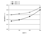
- FIG. 8 is a graph showing changes in thermal conductivity at various temperatures of wet silica and dry silica.
- FIG. 9 is a schematic diagram showing an assembled battery according to an embodiment of the present invention.
- FIG. 10 is a schematic diagram showing a method for measuring the scattering rate.
- FIG. 11 shows comparative example No. 3 and Example No. FIG.
- FIG. 12 shows comparative example No. 5 and Example No. 1 is a photograph substituted for a drawing showing the surface and cross section of No. 1.
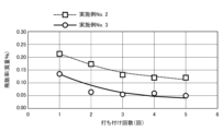
- FIG. 13 is a graph showing a change in the scattering rate with the number of hits, where the vertical axis is the scattering rate and the horizontal axis is the number of hits.
- the present inventors have conducted intensive studies on a heat transfer suppressing sheet that can solve the above problems.
- a heat transfer suppressing sheet using a dry method using binder fibers with a core-sheath structure that has a core with a high melting point and a sheath with a low melting point, high strength can be obtained using the core as a skeleton. It has been found that in addition to being able to hold the inorganic particles by melting the sheath, powder falling can be suppressed.
- a heat transfer suppressing sheet when heating the sheet material, if the heating temperature is set so as not to melt the core part, only the sheath part with a low melting point can be melted. Thereafter, by cooling, the sheath part, including the surrounding inorganic particles, is welded to the core part again. Therefore, after cooling, the core and the welded part containing the inorganic particles serve as a skeleton, and the strength of the heat transfer suppressing sheet can be improved. Further, since the sheath portion is melted and welded to the core portion together with the inorganic particles, the inorganic particles on the surface of the heat transfer suppressing sheet are retained on the sheet surface, so that powder falling can be suppressed. As a result, even when pressure or impact is applied to the heat transfer suppressing sheet, high heat insulation performance can be maintained.
- FIG. 1 is a schematic diagram illustrating a state after mixing raw materials, which is part of a method for manufacturing a heat transfer suppressing sheet according to a first embodiment of the present invention.
- FIG. 2 is a schematic diagram showing the structure of a heat transfer suppressing sheet manufactured by the manufacturing method according to the first embodiment of the present invention, and
- FIG. 3 is a sectional view thereof.
- FIG. 4 is a photograph substituted for a drawing showing an enlarged view of the heat transfer suppressing sheet according to the first embodiment of the present invention.
- binder fibers 3 having a core-sheath structure and inorganic particles 4 are put into a mixer such as a V-type mixer at a predetermined ratio to prepare a mixture 9.
- a solvent such as water, which is required when molding by a wet method, is not added to the mixture 9.
- a small amount of water is used within the range of the dry method. You may add a solvent such as.
- the binder fiber 3 has a core portion 1 extending in the longitudinal direction of the fiber, and a sheath portion 2 formed to cover the outer peripheral surface of the core portion 1, and the core portion 1 is made of a first organic material.
- the sheath portion 2 is made of a second organic material. Further, the melting point of the first organic material is higher than the melting point of the second organic material.
- the obtained mixture 9 is put into a predetermined mold and pressurized with a press or the like, and the obtained molded body (not shown) is heated.
- the sheath portion 2 of the binder fiber 3 is melted by heating, and a molten portion (not shown) containing inorganic particles present around the core portion 1 is formed.
- the molten sheath 2 is welded to the core 1 again, and the second organic material 7 constituting the sheath 2 is welded to the core 1.
- a welded portion 5 containing the inorganic particles 4 and a fiber portion 6 containing the core portion 1 are formed. Further, between the plurality of fiber parts 6, a base material part 8 containing inorganic particles 4 is formed. Thereby, the heat transfer suppressing sheet 10 processed into a sheet shape can be obtained.
- the manufacturing method according to the present embodiment since the melting point of the first organic material constituting the core portion 1 is higher than the melting point of the second organic material constituting the sheath portion 2, when heating the mixture 9, , the sheath part 2 can be melted while leaving the core part 1. Therefore, the strength of the heat transfer suppressing sheet 10 can be ensured by the core portion 1. Further, after cooling, the outer circumferential surface of the core portion 1 is covered with the second organic material 7 containing the inorganic particles 4 to form a welded portion 5, so that the inorganic particles 4 can be held. Further, the obtained fiber portion 6 has a large fiber diameter due to the core portion 1 and the welded portion 5, and therefore has higher strength than the strength of the core portion 1 alone.
- the binder fibers 3 are present in the mixture 9 in irregular directions, and the binder fibers 3 may be in contact with each other in some parts. Then, as shown in the contact part 11 in FIG. 4, when the molten sheath part 2 is cooled, the adjacent core parts 1 are fused to each other by the weld part 5, and a three-dimensional skeleton is formed. Ru. As a result, the shape of the entire heat transfer suppressing sheet can be maintained with even higher strength.
- an adhesive such as hot melt powder may be included in the mixture 9 as a raw material for the heat transfer suppressing sheet.
- the holding power of the inorganic particles 4 can be improved and powder falling can be further suppressed.
- the temperature when the temperature is set to melt only the surface of the organic fibers on the front side of the sheet, the surface of the organic fibers does not melt on the center side of the sheet, and the holding power of the inorganic particles 4 decreases. Additionally, if the temperature is set to melt the surface of the organic fibers on the center side of the sheet, the organic fibers on the surface side of the sheet will melt up to the radial center, making it difficult to ensure the strength of the sheet. .
- the core portion 1 since the melting point of the first organic material constituting the core portion 1 is higher than the melting point of the second organic material constituting the sheath portion 2, the core portion It is possible to set a temperature for melting the sheath part 2 while leaving a temperature of .
- the core part 1 serves as a skeleton that maintains the strength of the sheet on both the front side and the center side, and welded parts 5 containing inorganic particles 4 are formed on the surface of the core part 1. It has an ideal structure.
- the heat transfer suppressing sheet 10 manufactured by the manufacturing method according to the present embodiment has a strong skeleton, and even when a pressing force or impact is applied to the heat transfer suppressing sheet, its shape is maintained. In addition to being able to suppress powder falling, it is also possible to maintain excellent heat insulation performance.
- the surface of the heat transfer suppressing sheet 10 may be covered with a film or the like.
- Polymer films include polyimide, polycarbonate, PET, p-phenylene sulfide, polyetherimide, crosslinked polyethylene, flame-retardant chloroprene rubber, polyvinyldenfluoride, hard vinyl chloride, polybutylene terephthalate, PTFE, PFA, FEP, ETFE, Examples include films made of rigid PCV, flame-retardant PET, polystyrene, polyethersulfone, polyamideimide, polyacrylonitrile, polyethylene, polypropylene, polyamide, and the like.
- the method of covering the surface of the heat transfer suppressing sheet 10 with a film is not particularly limited, and may include a method of pasting with an adhesive, a method of wrapping the heat transfer suppressing sheet 10 with a film, a method of covering the surface of the heat transfer suppressing sheet 10 with a film, a method of covering the surface of the heat transfer suppressing sheet 10 with a film, a method of covering the surface of the heat transfer suppressing sheet 10 with a film, a method of covering the surface of the heat transfer suppressing sheet 10 with a film, a method of coating the surface of the heat transfer suppressing sheet 10 with a film, a method of coating the surface of the heat transfer suppressing sheet 10 with a film, a method of attaching it with an adhesive, etc. Examples include a method of accommodating the sheet 10.
- FIG. 5 is a schematic diagram showing the structure of a heat transfer suppressing sheet manufactured by the method for manufacturing a heat transfer suppressing sheet according to the second embodiment of the present invention.
- FIG. 6 is a photograph substituted for a drawing showing an enlarged view of the heat transfer suppressing sheet according to the second embodiment of the present invention.
- the second embodiment differs from the first embodiment only in materials, and the manufacturing process is the same as the method for manufacturing the heat transfer suppressing sheet according to the first embodiment.
- Components that are the same as those shown in 4 to 4 are given the same reference numerals, and their explanations will be omitted or simplified.
- binder fibers 3 having a core-sheath structure, inorganic particles 4, and hot melt powder are put into a mixer such as a V-type mixer at a predetermined ratio, and the mixture is mixed.
- the hot melt powder is a powder formed from a third organic material, such as ethylene-vinyl acetate (EVA). Note that the melting point of the hot melt powder is lower than the melting point of the first organic material constituting the core portion 1.
- the obtained mixture is put into a predetermined mold and pressurized with a press or the like, and the obtained molded body is heated, so that the sheath part 2 of the binder fiber 3 is melted and the hot melt powder is melt. Thereafter, by cooling the heated mixture, the molten sheath part 2 is welded to the core part 1 again, and the welded part 5 containing the second organic material 7 and inorganic particles 4 constituting the sheath part 2 is formed. It is formed.
- the welded part 5 covers at least a part of the surface of the core part 1 and constitutes a fiber part 6 together with the core part 1.
- the melted hot melt powder hardens while containing the surrounding inorganic particles 4, and the third organic material and inorganic particles constituting the hot melt powder are cured in all areas between the plurality of fiber parts 6. 4 is formed. In this way, the heat transfer suppressing sheet 13 according to the second embodiment can be obtained.
- the hot melt powder melted by heating tends to segregate on the surface of the molded body. Therefore, a thin hardened layer 17 is formed on the surface of the heat transfer suppressing sheet 13. Note that the hardened portion 16 includes thin hardened layers 17 dispersed in a plurality of regions, and cracks 12 may be formed between the plurality of hardened layers 17.
- the melting point of the first organic material constituting the core 1 is higher than the melting point of the second organic material constituting the sheath 2 and the melting point of the third organic material constituting the hot melt powder. Since it is higher than the melting point of the material, when heating the mixture 9, the sheath part 2 and the hot melt powder can be melted while leaving the core part 1. Therefore, the strength of the heat transfer suppressing sheet 13 can be ensured by the core portion 1.
- the sheath part 2 is welded to the core part 1 again in a state containing the surrounding inorganic particles 4, and a welded part 5 is formed, and the hot melt powder is welded in a state including the surrounding inorganic particles 4. It is cured, and a hardened portion 16 is formed. Therefore, not only the inorganic particles 4 can be held by the welded part 5, but also the inorganic particles 4 can be held by the hardened part 16 in the area excluding the welded part 5.
- the hot melt powder melted by heating tends to segregate on the surface of the molded body, and the surface of the heat transfer suppressing sheet 13 is covered with the thin hardened layer 17, so the inorganic particles 4 can be further suppressed from falling off.
- the heat transfer suppression sheet 13 when the heat transfer suppression sheet 13 is disposed between the plurality of battery cells, the As the battery cells expand and contract, the heat transfer suppressing sheet 13 becomes easily deformed. Therefore, damage to the heat transfer suppressing sheet 13 can be suppressed, and the load on adjacent battery cells can also be reduced.
- the hardened portion 16 containing hot melt powder and inorganic particles 4 supports the skeleton between the skeletons constituted by the fiber portions 6, the shape of the entire heat transfer suppressing sheet is maintained with even higher strength. As a result, even when pressure or impact is applied to the heat transfer suppressing sheet, high heat insulation performance can be maintained.
- the surface of the heat transfer suppressing sheet 13 may be covered with a film or the like in order to further suppress powder falling.
- the type of film and the method of coating with the film are as described above.
- the binder fiber 3 that can be used in this embodiment has a core-sheath structure, and the melting point of the first organic material forming the core part 1 is the melting point of the second organic material forming the sheath part 2. There is no particular limitation as long as it is higher than .
- the first organic material forming the core portion 1 at least one selected from polyethylene terephthalate, polypropylene, and nylon can be selected.
- the second organic material forming the sheath portion 2 at least one selected from polyethylene terephthalate, polyethylene, polypropylene, and nylon can be selected.
- the melting point of the first organic material constituting the core portion 1 is sufficiently higher than the melting point of the second organic material constituting the sheath portion 2, the setting latitude for the heating temperature in the heating process can be expanded. , it is possible to more easily set the temperature to obtain the desired structure.
- the melting point of the first organic material is preferably 60°C or more higher than the melting point of the second organic material, more preferably 70°C or more higher, and even more preferably 80°C or more higher.
- binder fibers having a core-sheath structure as described above are generally commercially available, and the materials constituting the core portion and the sheath portion may be the same or different from each other.
- binder fibers in which the core 1 and the sheath 2 are made of the same material and have different melting points include those in which the core 1 and the sheath 2 are made of polyethylene terephthalate, polypropylene, and nylon. Examples include things.
- binder fibers in which the core part 1 and the sheath part 2 are made of different materials include one in which the core part 1 is made of polyethylene terephthalate and the sheath part 2 is made of polyethylene, and one in which the core part 1 is made of polypropylene and the sheath part 2 is made of polyethylene. Examples include those made of polyethylene.
- the melting point of the second organic material constituting the sheath of the binder fibers refers to the melting temperature at which the second organic material begins to melt and deform. Judging to be a species.
- the melting point of the sheath portion of the binder fiber can be measured, for example, by the following method. A binder fiber to be measured is placed in contact with a glass fiber having a higher melting point, heated from room temperature to 200° C. at a heating rate of 5° C./min, and then cooled to room temperature.
- the second organic It can be determined that the melting point of the material is 200°C or lower.
- the sheath portion is constructed by varying the heating temperature and observing the fused state of the binder fibers and glass fibers after cooling by the above method, or the cross-sectional shape of the binder fibers. The melting point of the second organic material can be determined.
- the content of the binder fibers 3 is preferably 5% by mass or more, more preferably 10% by mass or more based on the total mass of the mixture 9. Furthermore, if the content of the binder fibers 3 becomes too large, the content of the inorganic particles 4 will be relatively reduced, so in order to obtain the desired heat insulation performance, the content of the binder fibers 3 must be It is preferably 25% by mass or less, more preferably 20% by mass or less based on the mass.
- the content of the inorganic particles 4 in the mixture 9 is appropriately controlled, sufficient heat insulation properties in the resulting heat transfer suppressing sheet 10 can be ensured.
- the content of all the inorganic particles 4 contained in the mixture 9 is preferably 60% by mass or more, more preferably 70% by mass or more based on the total mass of the mixture 9. Furthermore, if the content of the inorganic particles 4 becomes too large, the content of the binder fibers 3 will be relatively reduced. It is preferably 95% by mass or less, more preferably 90% by mass or less based on the total mass of.
- the mixture 9 may contain a hot melt powder (not shown).
- the hot melt powder is a powder that contains, for example, a third organic material different from the first organic material and the second organic material, and has the property of being melted by heating. By including hot melt powder in the mixture 9 and heating it, the hot melt powder is melted, and when it is cooled thereafter, it hardens while containing the surrounding inorganic particles 4, and a hardened portion 16 is formed.
- the hardened portion 16 includes the thin hardened layer 17 dispersed in a plurality of regions on the surface of the heat transfer suppression sheet 13, and since the surface of the heat transfer suppression sheet 13 is covered with the thin hardened layer, heat is not absorbed. Falling off of the inorganic particles 4 from the transmission suppression sheet 13 can be further suppressed.
- Hot melt powders include those having various melting points, but a hot melt powder having an appropriate melting point may be selected in consideration of the melting points of the core 1 and sheath 2 of the binder fibers 3 used. .
- the heating temperature can be set to melt the sheath 2 and the hot melt powder while leaving the core 1 intact.
- the melting point of the hot melt powder is lower than the melting point of the sheath part 2
- the heating temperature during production can be set between the melting point of the core part 1 and the melting point of the sheath part 2, making it easier.
- the heating temperature can be set to .
- the type of hot melt powder to be used can also be selected so that the melting point of the hot melt powder is between the melting point of the core part 1 and the melting point of the sheath part 2.
- a hot melt powder having such a melting point is used, when the sheath part 2 and the hot melt powder are both melted and then cooled and hardened, the organic fiber (core part 1) and the molten sheath around it first melt.
- the hot melt powder present in all areas except part 2 is cured.
- the position of the organic fibers can be fixed, and then the molten sheath portion 2 is welded to the organic fibers, making it easier to form a three-dimensional skeleton. Therefore, the strength of the entire sheet can be further improved.
- the melting point of the third organic material constituting the hot melt powder is sufficiently lower than the melting point of the first organic material constituting the core 1, the setting latitude for the heating temperature in the heating process can be expanded. , it is possible to more easily set the temperature to obtain the desired structure.
- the melting point of the first organic material is preferably 60°C or more higher than the melting point of the third organic material, more preferably 70°C or more higher, and even more preferably 80°C or more higher.
- the components constituting the hot melt powder include polyethylene, polyester, polyamide, ethylene vinyl acetate, and the like.
- the content of the hot melt powder is preferably 0.5% by mass or more, more preferably 1% by mass or more based on the total mass of the mixture 9.
- the content of the hot melt powder is increased, the content of the inorganic particles 4 is relatively decreased. Therefore, in order to obtain the desired insulation performance, the content of the hot melt powder must be adjusted to the total mass of the mixture 9. It is preferably 5% by mass or less, more preferably 4% by mass or less.
- the process of processing the mixture 9 into a sheet shape includes a process of pressurizing the mixture 9 and a process of heating the mixture 9.
- the heating temperature in the heating step is preferably higher than the melting point of the second organic material forming the sheath 2 and lower than the melting point of the first organic material forming the core 1.
- the melting point of the first organic material forming the core part 1 is sufficiently higher than the melting point of the second organic material forming the sheath part 2, the setting latitude for the heating temperature in the heating process can be expanded. This makes it easier to set the temperature to obtain the desired structure.
- the melting point of the first organic material is preferably 60°C or more higher than the melting point of the second organic material, more preferably 70°C or more higher, and even more preferably 80°C or more higher.
- the heating temperature in the heating step is preferably set to be 10° C. or more higher than the melting point of the second organic material constituting the sheath 2, and more preferably 20° C. or more higher.
- the heating temperature is preferably set at least 10°C lower than the melting point of the first organic fiber constituting the core 1, and more preferably set at least 20°C lower.
- the heating time is not particularly limited, but it is preferable to set the heating time so that the sheath portion 2 can be sufficiently melted.
- it can be set to 3 minutes or more and 15 minutes or less.
- the heating temperature in the heating step is the melting point of the second organic material constituting the sheath 2 and the hot melt powder.
- the melting point of the third organic material constituting the powder is preferably set at least 10°C higher than whichever is higher, and more preferably set at least 20°C higher.
- the heating temperature is preferably set at least 10°C lower than the melting point of the first organic material constituting the core 1, and more preferably set at least 20°C lower.
- the heat transfer suppressing sheet according to the present embodiment includes inorganic particles 4, organic fibers (core portion 1) made of a first organic material, and an outer circumferential surface of the organic fibers. It has a welded part 5. As described above, the welded portion 5 includes the second organic material 7 having a melting point lower than the melting point of the first organic material and the inorganic particles 4.
- the heat transfer suppressing sheet 10 configured in this way, the above [1.
- the organic fibers (core portion 1) and the welded portions 5 act as a skeleton, so excellent strength and shape retention can be obtained.
- the welded part 5 covering the outer peripheral surface of the organic fibers fixes the inorganic particles 4 to the organic fibers (core part 1). Falling can be suppressed. Therefore, for example, even if the heat transfer suppressing sheet 10 according to the present embodiment is placed between a plurality of battery cells described below and the battery cells expand and compressive stress or impact is applied to the heat transfer suppressing sheet 10, , can maintain excellent heat insulation performance.
- the organic fibers (core portion 1) and welded portions 5 have a three-dimensional and strong skeleton.
- One of the reasons is considered to be that the shape of the heat transfer suppressing sheet 10 is maintained, so deformation or compression of the heat transfer suppressing sheet 10 is suppressed.
- the fact that the fiber part 6 consisting of the organic fiber (core part 1) and the welded part 5 exposed on the sheet surface can absorb the impact given to the heat transfer suppressing sheet 10 also means that the inorganic particles 4 This may be the reason why it is retained.
- the welded portion 5 does not need to completely cover the outer peripheral surface of the organic fiber (core portion 1), but partially covers the outer peripheral surface of the organic fiber (core portion 1). ) may be exposed.
- the sheath portion 2 since the binder fibers 3 having a core-sheath structure are used, the sheath portion 2 may peel off during the manufacturing process; Even if 1) is exposed, the effects of the present invention can be fully obtained.
- FIGS. 5 and 6 A second embodiment of a heat transfer suppressing sheet manufactured by the method for manufacturing a heat transfer suppressing sheet according to the second embodiment will be described below.
- the sheath portion of the binder fibers having a core-sheath structure is reattached to the core portion, similar to the example of the heat transfer suppressing sheet according to the first embodiment shown in FIG. It is welded to 1.
- the fiber part 6 is constituted by the core part 1 and the weld part 5 containing the second organic material and inorganic particles 4 that constitute the sheath part.
- adjacent core parts 1 are fused to each other by a welding part 5 to form a contact part 11.
- a hardened portion 16 containing a third organic material constituting hot melt powder and inorganic particles is formed. Further, the hardened portion 16 has a plurality of hardened layers 17 on the surface of the heat transfer suppressing sheet 13, and cracks 12 are formed between the plurality of hardened layers 17.
- the hot melt powder will be present in all areas of the molded product, so when the welded part 5 is cooled after heating in the manufacturing process, the hot melt powder will be present in the welded part 5.
- a third organic material may be included that is a component of.
- the hardened portion 16 may contain a second organic material that is a component of the sheath portion 2 . In either case, the effects of the present invention are not affected.
- the hardened portion 16 containing hot melt powder and inorganic particles 4 supports the skeleton between the skeletons. Therefore, the shape of the entire heat transfer suppressing sheet can be maintained with even higher strength. Further, the outer circumferential surface of the organic fiber is covered with the welded part 5, and the hardened part 16 is formed even in the area excluding the welded part 5, so that the inorganic particles 4 can be held. Furthermore, since the thin hardened layer 17 is formed on the surface of the heat transfer suppressing sheet 13, a high powder drop suppression effect can be obtained.
- the heat transfer suppressing sheet 13 easily follows deformation accompanying expansion and contraction of the battery cells during charging and discharging. Therefore, for example, even if the heat transfer suppressing sheet 13 according to the present embodiment is placed between a plurality of battery cells described below, and the battery cells expand and compressive stress or impact is applied to the heat transfer suppressing sheet 13, , can maintain excellent heat insulation performance.
- the core portion 1 made of the first organic material acts as an organic fiber that maintains the strength and shape of the sheet.
- the first organic material constituting the organic fiber is not particularly limited as long as it has a melting point higher than the second organic material present on the outer peripheral surface of the organic fiber.
- the first organic material includes at least one selected from polyethylene terephthalate, polypropylene, and nylon.
- the content of organic fibers is preferably 2% by mass or more, more preferably 4% by mass or more based on the total mass of the heat transfer suppressing sheet 10. Furthermore, if the content of organic fibers becomes too large, the content of inorganic particles 4 will be relatively reduced, so in order to obtain the desired heat insulation performance, the content of organic fibers must be adjusted to It is preferably 10% by mass or less, more preferably 8% by mass or less based on the total mass.
- the fiber length of the organic fibers is not particularly limited, but from the viewpoint of ensuring moldability and processability, the average fiber length of the organic fibers is preferably 10 mm or less. On the other hand, from the viewpoint of making the organic fibers function as a skeleton and ensuring the compressive strength of the heat transfer suppressing sheet, the average fiber length of the organic fibers is preferably 0.5 mm or more.
- the welded part 5 is formed by once melting the sheath part 2 of the binder fiber 3 having a core-sheath structure by heating and then cooling it, and includes the second organic material 7 and the inorganic particles 4.
- the second organic material is not particularly limited as long as it has a melting point lower than the first organic material constituting the organic fiber.
- the second organic material includes at least one selected from polyethylene terephthalate, polyethylene, polypropylene, and nylon. Note that the melting point of the second organic material is preferably 90°C or higher, more preferably 100°C or higher. Further, the melting point of the second organic material is preferably 150°C or lower, more preferably 130°C or lower.
- the manufactured heat transfer suppressing sheet has a hardened portion 16.
- the hardened portion 16 is formed by once melting the hot melt powder by heating and then cooling it, and includes the third organic material and inorganic particles 4 that constitute the hot melt powder.
- the third organic material which is a component constituting the hot melt powder is not particularly limited as long as it has a melting point lower than the first organic material constituting the organic fiber.
- the melting point of the hot melt powder (third organic material) is preferably lower than the melting point of the second organic material constituting the sheath.
- the melting point of the third organic material is different from the melting point of the first organic material and the melting point of the second organic material. It may be made to be between.
- the melting point of the hot melt powder (third organic material) is preferably 80°C or higher, more preferably 90°C or higher.
- the melting point of the hot melt powder is preferably 180°C or lower, more preferably 150°C or lower.
- the third organic material constituting the hot melt powder is at least one selected from polyethylene, polyester, polyamide, and ethylene vinyl acetate.
- inorganic particles As the inorganic particles, a single inorganic particle may be used, or two or more types of inorganic particles may be used in combination. As for the type of inorganic particles, it is preferable to use particles made of at least one inorganic material selected from oxide particles, carbide particles, nitride particles, and inorganic hydrate particles from the viewpoint of heat transfer suppressing effect. , it is more preferable to use oxide particles. Further, the shape is not particularly limited, but it is preferable to include at least one selected from nanoparticles, hollow particles, and porous particles, and specifically, silica nanoparticles, metal oxide particles, microporous particles, and hollow particles. Inorganic balloons such as silica particles, particles made of a thermally expandable inorganic material, particles made of a hydrous porous material, etc. can also be used.
- the average secondary particle diameter of the inorganic particles is 0.01 ⁇ m or more, they are easily available and can suppress an increase in manufacturing costs. Further, when the thickness is 200 ⁇ m or less, a desired heat insulation effect can be obtained. Therefore, the average secondary particle diameter of the inorganic particles is preferably 0.01 ⁇ m or more and 200 ⁇ m or less, more preferably 0.05 ⁇ m or more and 100 ⁇ m or less.
- the heating element can be cooled in multiple stages, and the endothermic effect can be exerted over a wider temperature range.
- a mixture of large diameter particles and small diameter particles it is preferable to use a mixture of large diameter particles and small diameter particles.
- the other inorganic particles include inorganic particles made of a metal oxide.
- the inorganic particles will be described in more detail, with small-diameter inorganic particles being referred to as first inorganic particles and large-diameter inorganic particles being referred to as second inorganic particles.
- Oxide particles have a high refractive index and have a strong effect of diffusely reflecting light, so when oxide particles are used as the first inorganic particles, radiant heat transfer can be suppressed, particularly in high temperature regions such as abnormal heat generation.
- oxide particles at least one particle selected from silica, titania, zirconia, zircon, barium titanate, zinc oxide, and alumina can be used. That is, among the above-mentioned oxide particles that can be used as inorganic particles, only one type or two or more types of oxide particles may be used.
- silica is a component with high heat insulation properties
- titania is a component with a high refractive index compared to other metal oxides, and is highly effective in diffusely reflecting light and blocking radiant heat in high temperature regions of 500 degrees Celsius or higher. Therefore, it is most preferable to use silica and titania as the oxide particles.
- Average primary particle diameter of oxide particles 0.001 ⁇ m or more and 50 ⁇ m or less
- the average primary particle diameter of the oxide particles is 0.001 ⁇ m or more, it is sufficiently larger than the wavelength of the light that contributes to heating, and in order to diffusely reflect light efficiently, it is difficult to transfer heat in the high temperature region of 500°C or more. The radiant heat transfer within the suppression sheet is suppressed, and the heat insulation properties can be further improved.
- the average primary particle diameter of the oxide particles is 50 ⁇ m or less, the number of contact points between the particles does not increase even when the particles are compressed, and it is difficult to form a path for conductive heat transfer, so conductive heat transfer is particularly dominant. The influence on the heat insulation properties in the normal temperature range can be reduced.
- the average primary particle diameter can be determined by observing the particles with a microscope, comparing them with a standard scale, and taking the average of 10 arbitrary particles.
- nanoparticles refer to nanometer-order particles having a spherical or nearly spherical average primary particle diameter of less than 1 ⁇ m. Because nanoparticles have a low density, they suppress conductive heat transfer, and when nanoparticles are used as the first inorganic particles, the voids are further finely dispersed, making it possible to obtain excellent heat insulation properties that suppress convective heat transfer. . For this reason, it is preferable to use nanoparticles because they can suppress the conduction of heat between adjacent nanoparticles during normal use of the battery in the normal temperature range.
- the heat transfer suppressing sheet will be compressed by the expansion caused by thermal runaway of the battery cell, and even if the internal density increases, the heat transfer will be reduced. It is possible to suppress an increase in conductive heat transfer of the suppression sheet. This is thought to be because nanoparticles tend to form fine voids between particles due to the repulsive force caused by static electricity, and because their bulk density is low, the particles are filled so as to provide cushioning properties.
- the material when using nanoparticles as the first inorganic particles, is not particularly limited as long as it meets the above definition of nanoparticles.
- silica nanoparticles in addition to being a highly insulating material, silica nanoparticles have small contact points between particles, so the amount of heat conducted by silica nanoparticles is smaller than when using silica particles with a large particle size. Become.
- silica nanoparticles have a bulk density of about 0.1 (g/cm 3 ), so for example, battery cells placed on both sides of a heat insulating sheet may thermally expand, causing Even when a large compressive stress is applied to the silica nanoparticles, the size (area) and number of contact points between the silica nanoparticles do not increase significantly, and the heat insulation properties can be maintained. Therefore, it is preferable to use silica nanoparticles as the nanoparticles. Examples of silica nanoparticles include wet silica, dry silica, and airgel, and silica nanoparticles that are particularly suitable for this embodiment will be described below.
- FIG. 7 is a photograph substituted for a drawing showing the state of particles of wet silica and dry silica.
- FIG. 8 is a graph diagram showing the change in thermal conductivity at each temperature of wet silica and dry silica.
- particles of wet silica are aggregated, whereas particles of dry silica can be dispersed.
- conductive heat transfer is dominant, so as shown in Figure 8, dry silica, which can disperse particles, is superior to wet silica. It is possible to obtain excellent insulation performance.
- a mixture containing the materials is processed into a sheet shape by a dry method. Therefore, as the inorganic particles, it is preferable to use dry silica, silica airgel, etc., which have low thermal conductivity.
- Average primary particle diameter of nanoparticles 1 nm or more and 100 nm or less
- the average primary particle diameter of the nanoparticles is set to 1 nm or more and 100 nm or less, convective heat transfer and conductive heat transfer within the heat transfer suppressing sheet can be suppressed, especially in the temperature range below 500°C, and the heat insulation property is improved. can be further improved.
- the voids remaining between nanoparticles and the many contact points between particles suppress conductive heat transfer, and the heat insulation properties of the heat transfer suppressing sheet can be maintained. .
- the average primary particle diameter of the nanoparticles is more preferably 2 nm or more, and even more preferably 3 nm or more.
- the average primary particle diameter of the nanoparticles is more preferably 50 nm or less, and even more preferably 10 nm or less.
- Inorganic hydrate particles thermally decompose when they receive heat from a heating element and reach a thermal decomposition start temperature, releasing their own water of crystallization and lowering the temperature of the heating element and its surroundings, a so-called "endothermic action.” Express. Furthermore, after releasing the crystal water, it becomes a porous body and exhibits a heat insulating effect due to its countless air holes.
- Specific examples of inorganic hydrates include aluminum hydroxide (Al(OH) 3 ), magnesium hydroxide (Mg(OH) 2 ), calcium hydroxide (Ca(OH) 2 ), and zinc hydroxide (Zn(OH)).
- aluminum hydroxide has about 35% water of crystallization, and as shown in the following formula, it thermally decomposes to release water of crystallization and exhibits an endothermic action. After releasing the crystal water, it becomes porous alumina (Al 2 O 3 ), which functions as a heat insulator. 2Al(OH) 3 ⁇ Al 2 O 3 +3H 2 O
- the heat transfer suppressing sheet 10 is preferably interposed between, for example, battery cells; however, in battery cells that have undergone thermal runaway, The temperature rises rapidly and continues to rise to around 700°C. Therefore, the inorganic particles are preferably composed of inorganic hydrates whose thermal decomposition initiation temperature is 200° C. or higher.
- the thermal decomposition starting temperatures of the inorganic hydrates listed above are approximately 200°C for aluminum hydroxide, approximately 330°C for magnesium hydroxide, approximately 580°C for calcium hydroxide, approximately 200°C for zinc hydroxide, and approximately 200°C for iron hydroxide.
- the average secondary particle diameter of the inorganic hydrate particles is preferably 0.01 ⁇ m or more and 200 ⁇ m or less, more preferably 0.05 ⁇ m or more and 100 ⁇ m or less.
- thermally expandable inorganic material examples include vermiculite, bentonite, mica, pearlite, and the like.
- Water-containing porous material particles made of water-containing porous material
- water-containing porous material include zeolite, kaolinite, montmorillonite, acid clay, diatomaceous earth, wet silica, dry silica, aerogel, mica, and vermiculite.
- the heat insulating material used in the present invention may contain an inorganic balloon as the first inorganic particles.
- an inorganic balloon When an inorganic balloon is included, convection heat transfer or conductive heat transfer within the heat insulating material can be suppressed in a temperature range of less than 500° C., and the heat insulating properties of the heat insulating material can be further improved.
- the inorganic balloon at least one selected from a shirasu balloon, a silica balloon, a fly ash balloon, a barite balloon, and a glass balloon can be used.
- Inorganic balloon content 60% by mass or less based on the total mass of the insulation material
- the content of the inorganic balloon is preferably 60% by mass or less based on the total mass of the heat insulating material.
- the average particle diameter of the inorganic balloon is preferably 1 ⁇ m or more and 100 ⁇ m or less.
- the second inorganic particles are not particularly limited as long as they are different from the first inorganic particles in material, particle size, etc.
- the second inorganic particles include oxide particles, carbide particles, nitride particles, inorganic hydrate particles, silica nanoparticles, metal oxide particles, inorganic balloons such as microporous particles and hollow silica particles, and thermally expandable inorganic materials. Particles made of a water-containing porous material, particles made of a water-containing porous material, etc. can be used, and the details thereof are as described above.
- nanoparticles have extremely low conductive heat transfer and can maintain excellent heat insulation properties even when compressive stress is applied to the heat transfer suppressing sheet. Furthermore, metal oxide particles such as titania are highly effective in blocking radiant heat. Furthermore, when large-diameter inorganic particles and small-diameter inorganic particles are used, the small-diameter inorganic particles enter the gaps between the large-diameter inorganic particles, resulting in a more dense structure and improving the heat transfer suppression effect. can. Therefore, when nanoparticles, for example, are used as the first inorganic particles, particles made of a metal oxide having a larger diameter than the first inorganic particles are further used as the second inorganic particles to suppress heat transfer. It is preferable to include it in the sheet.
- metal oxides examples include silicon oxide, titanium oxide, aluminum oxide, barium titanate, zinc oxide, zircon, and zirconium oxide.
- titanium oxide titanium oxide (titania) is a component with a high refractive index compared to other metal oxides, and is highly effective in diffusely reflecting light and blocking radiant heat in the high temperature range of 500°C or higher, so titania can be used. Most preferred.
- At least one particle selected from dry silica particles and silica aerogel was used as the first inorganic particle, and the second inorganic particle was selected from titania, zircon, zirconia, silicon carbide, zinc oxide, and alumina.
- the first inorganic particles in order to obtain excellent heat insulation performance within a temperature range of 300°C or less, the first inorganic particles must be present in an amount of 50% by mass or more based on the total mass of the inorganic particles. It is preferably at least 60% by mass, more preferably at least 70% by mass.
- the content of the first inorganic particles is preferably 95% by mass or less, more preferably 90% by mass or less, and even more preferably 80% by mass or less, based on the total mass of the inorganic particles.
- the second inorganic particles are preferably 5% by mass or more, and 10% by mass or more based on the total mass of the inorganic particles. More preferably, it is 20% by mass or more. Further, the second inorganic particles account for preferably 50% by mass or less, more preferably 40% by mass or less, and even more preferably 30% by mass or less, based on the total mass of the inorganic particles.
- the heat transfer suppressing sheet contains second inorganic particles made of a metal oxide, if the average primary particle diameter of the second inorganic particles is 1 ⁇ m or more and 50 ⁇ m or less, efficiency is improved in a high temperature region of 500°C or higher. Radiation heat transfer can be well suppressed.
- the average primary particle diameter of the second inorganic particles is more preferably 5 ⁇ m or more and 30 ⁇ m or less, and most preferably 10 ⁇ m or less.
- the content of the inorganic particles 4 is preferably 60% by mass or more, more preferably 70% by mass or more based on the total mass of the heat transfer suppressing sheet 10. Furthermore, if the content of inorganic particles 4 becomes too large, the content of organic fibers and welded parts will be relatively reduced.
- the content of 4 is preferably 95% by mass or less, more preferably 90% by mass or less based on the total mass of the heat transfer suppressing sheet 10.
- the content of inorganic particles in the heat transfer suppressing sheet 10 can be calculated, for example, by heating the heat transfer suppressing sheet at 800° C., decomposing the organic components, and then measuring the mass of the remaining portion.
- the heat transfer suppressing sheet according to the present embodiment also includes organic fibers made of an organic material different from the first organic material, and inorganic fibers. etc. may be included.
- the base material portion 8 may include an organic material different from the first organic material and the second organic material, and the inorganic particles may be held in this organic material.
- the thickness of the heat transfer suppressing sheet according to this embodiment is not particularly limited, it is preferably 0.05 mm or more and 10 mm or less. When the thickness is 0.05 mm or more, sufficient compressive strength can be obtained. On the other hand, when the thickness is 10 mm or less, good heat insulation properties of the heat transfer suppressing sheet can be obtained.
- FIG. 9 is a schematic diagram showing an assembled battery according to an embodiment of the present invention.
- the assembled battery 100 according to the present embodiment includes a plurality of battery cells 20a, 20b, and 20c and a heat transfer suppression sheet according to the present embodiment, and the plurality of battery cells are connected in series or in parallel. It is.
- the heat transfer suppressing sheet 10 according to the present embodiment is interposed between a battery cell 20a and a battery cell 20b, and between a battery cell 20b and a battery cell 20c.
- the battery cells 20a, 20b, 20c and the heat transfer suppression sheet 10 are housed in a battery case 30. Note that the heat transfer suppressing sheet 10 is as described above.
- the heat transfer suppressing sheet 10 having a heat transfer suppressing effect exists between it and the battery cell 20b. , it is possible to suppress the propagation of heat to the battery cell 20b. Moreover, since the heat transfer suppressing sheet 10 according to the present embodiment has high compressive strength, it is possible to suppress thermal expansion of the battery cells 20a, 20b, and 20c even during charging and discharging of these battery cells. Therefore, the distance between the battery cells can be ensured, excellent heat insulation performance can be maintained, and thermal runaway of the battery cells can be prevented. Moreover, since it has the effect of suppressing powder falling, it can be easily handled.
- a heat transfer suppressing sheet 10 may also be placed between the cells 20a, 20b, 20c and the battery case 30.
- the assembled battery 100 configured in this way, when a certain battery cell ignites, it is possible to suppress the flame from spreading to the outside of the battery case 30.
- the assembled battery 100 according to this embodiment is used in an electric vehicle (EV) or the like, and may be placed under a passenger's floor. In this case, even if the battery cell catches fire, the safety of the passenger can be ensured.
- the heat transfer suppressing sheet 10 can be placed not only between each battery cell but also between the battery cells 20a, 20b, 20c and the battery case 30, a new flame retardant material etc. can be prepared. There is no need to do so, and the assembled battery 100 can be easily configured at low cost and safe.
- the heat transfer suppressing sheet 10 according to the present embodiment can be manufactured into various shapes depending on the manufacturing method. Therefore, it is not affected by the shapes of the battery cells 20a, 20b, 20c and the battery case 30, and can be adapted to any shape. Specifically, it can be applied to cylindrical batteries, flat batteries, etc. in addition to prismatic batteries.
- Test materials for heat transfer suppression sheets were prepared using various materials by a dry method or a wet method, and the heat insulation performance and powder fall suppression performance (scattering rate) were evaluated.
- Example No. 1 Pyrosilica and titania were prepared as inorganic particles, and binder fibers with a core-sheath structure were also prepared. The specific content and name of each component are shown below.
- ⁇ Inorganic particles dry silica (60% by mass, average primary particle diameter: 0.012 ⁇ m)
- ⁇ Inorganic particles titania (25% by mass, average primary particle diameter: 8 ⁇ m)
- Core Polyethylene terephthalate (melting point: 240°C)
- Sheath Low melting point polyethylene terephthalate (melting point: 110°C)
- Example No. 1 with a basis weight of 740 (g/m 2 ) and a thickness of 2 mm. ..
- a test material of No. 1 was obtained. Note that the heating conditions were 150° C. for 15 minutes.
- the content of organic fibers (core) in the obtained test material was 7% by mass based on the total mass of the test material.
- inorganic particles dry silica and titania were prepared, as well as a single-component binder fiber. The specific content and name of each component are shown below.
- ⁇ Inorganic particles dry silica (60% by mass, average primary particle diameter: 0.012 ⁇ m)
- ⁇ Inorganic particles titania (25% by mass, average primary particle diameter: 8 ⁇ m)
- ⁇ Binder fiber low melting point polyethylene terephthalate (15% by mass, melting point: 130°C, average fiber length: 5mm)
- Example No. Comparative example No. 1 having a basis weight of 740 (g/m 2 ) and a thickness of 2 mm was prepared by the same dry method as in No. 1.
- a test material No. 1 was prepared. Note that the heating conditions were 160° C. for 15 minutes.
- Example No. Comparative example No. 1 having a basis weight of 740 (g/m 2 ) and a thickness of 2 mm was prepared by the same dry method as in No. 1.
- No. 2 test materials were prepared. Note that the heating conditions were 160° C. for 15 minutes.
- the above material was dispersed in water using a pulper to prepare a uniform papermaking slurry (dispersion), and then dehydrated using a papermaking machine to obtain a wet sheet. Thereafter, it was dried using a Yankee dryer with a surface temperature of 140°C, and then heated to 250°C by hot air drying to obtain a dry sheet. Thereafter, by cooling the dry sheet, Comparative Example No. 1 having a basis weight of 740 (g/m 2 ) and a thickness of 2 mm was prepared. No. 3 test materials were prepared.
- Example No. 4 As the inorganic particles, Example No. 4, As the inorganic particles, Example No. 4, As the inorganic particles, Example No. 4, As the inorganic particles, Example No. 4, As the inorganic particles, Example No. 4, As the inorganic particles, Example No. 4, As the inorganic particles, Example No. 4, In addition to preparing the same dry silica and titania as in Example 1, binder fibers having a core-sheath structure were also prepared. The specific content and name of each component are shown below. ⁇ Inorganic particles: dry silica (60% by mass, average primary particle diameter: 0.012 ⁇ m) ⁇ Inorganic particles: titania (25% by mass, average primary particle diameter: 8 ⁇ m) ⁇ Binder fiber (15% by mass, average fiber length: 5mm) Core: Polyethylene terephthalate (melting point: 240°C) Sheath: Low melting point polyethylene terephthalate (melting point: 110°C)
- Comparative Example No. Comparative Example No. 3 having a basis weight of 740 (g/m 2 ) and a thickness of 2 mm was prepared using the same wet method as in No. 3. 4 test materials were prepared. Note that the heating conditions were also the same as that of Comparative Example No. The same conditions as 3 were used.
- Thermal conductivity (W/m ⁇ K) was measured at room temperature (25° C.). Note that the thermal conductivity was measured by an unsteady hot wire method in accordance with ISO8894-1. In addition, those whose thermal conductivity was 0.05 or less were judged to have good heat insulation properties. Further, those whose thermal conductivity exceeded 0.05 were judged to have poor heat insulation properties.
- FIG. 10 is a schematic diagram showing a method for measuring the scattering rate.
- an apparatus was used in which an arm 25 was attached so as to operate at the apex of a support column 24, and a test material 23 was attached to the tip of the arm 25.
- the test material 23 was attached to the tip of the arm 25, and then the arm 25 was pulled up to an arbitrary angle and fixed, and then the fixation was released and the arm 25 was allowed to fall, causing the support 24 and the arm 25 to collide, giving a shock.
- the size of the test material 23 was 50 mm x 50 mm, the arm length was 915 mm, the impact was applied once, and the angle between the column and the arm was 90°.
- FIG. 11 shows comparative example No. 3 and Example No.
- FIG. 1 is a graph diagram showing changes in thermal conductivity at various temperatures in FIG.
- Example No. Sample No. 1 was a test material of a heat transfer suppressing sheet prepared by a dry method, and thus it was able to obtain excellent heat insulation properties compared to the comparative example. Furthermore, since titania was used as the inorganic particles, excellent heat insulation properties were obtained even in a temperature range of 300° C. or higher. Furthermore, Example No. Since Sample No. 1 contained binder fibers with a core-sheath structure as a material, the scattering rate E was 0.15% by mass or less, and good powder fall suppression performance could be obtained.
- comparative example No For samples 1 to 4, single-component binder fiber was used as the material or the test material was prepared by a wet method, so the evaluation results for at least one of the insulation properties and powder fall suppression performance were poor. Ta.
- Comparative Example No. 1 was manufactured using a manufacturing method that differs from the present invention. 5 and the above Example No. 5 test material.
- a photograph was taken using a scanning electron microscope (SEM).
- comparative example No. Test material No. 5 contained wet silica and glass fiber and was manufactured by a wet method.
- FIG. 12 shows comparative example No. 5 and Example No. 1 is a photograph substituted for a drawing showing the surface and cross section of No. 1.
- comparative example No. Since sample No. 5 used glass fibers, no inorganic particles were welded to the surface of the fibers, and there was no welding of the fibers to each other. Furthermore, since the test material was produced by a wet method, the inorganic particles were aggregated.
- Example No. In No. 1 since a binder fiber having a core-sheath structure was used, a welded portion containing inorganic particles was formed on the outer peripheral surface of the organic fiber serving as the core, and a large diameter fiber portion was obtained. In addition, in areas where multiple organic fibers are close to each other, it can be observed that the large diameter fibers form a three-dimensional and strong skeleton because the multiple organic fibers are fixed by welds. Ta.
- Example No. 2 Pyrosilica and titania were prepared as inorganic particles, and binder fibers with a core-sheath structure were also prepared. The specific content and name of each component are shown below.
- ⁇ Inorganic particles dry silica (60% by mass, average primary particle diameter: 0.012 ⁇ m)
- ⁇ Inorganic particles titania (25% by mass, average primary particle diameter: 8 ⁇ m)
- ⁇ Binder fiber PET/low melting point PET fiber (TJ04CN: manufactured by Teijin Frontier Ltd.: 15% by mass, average fiber length: 5mm)
- Core Polyethylene terephthalate (melting point: 240°C)
- Sheath Low melting point polyethylene terephthalate (melting point: 110°C)
- Example No. Example No. 1 having a basis weight of 740 (g/m 2 ) and a thickness of 2 mm was prepared by the same dry method as in Example No. 1. No. 2 test material was obtained. Note that the heating conditions were 150° C. for 15 minutes.
- Example No. 3 The above Example No. A material prepared by adding hot melt powder to the ingredients of 2 was prepared. The specific content and name of each component are shown below.
- ⁇ Inorganic particles dry silica (57.7% by mass, average primary particle diameter: 0.012 ⁇ m)
- Inorganic particles titania (24.7% by mass, average primary particle diameter: 8 ⁇ m)
- Hot melt powder Powder resin (PR D60C-Z: manufactured by Tokyo Ink Co., Ltd., 2.6% by mass, melting point: 100°C)
- ⁇ Binder fiber PET/low melting point PET fiber (TJ04CN: manufactured by Teijin Frontier Co., Ltd.: 15 Mass%, average fiber length: 5mm)
- Core Polyethylene terephthalate (melting point: 240°C)
- Sheath Low melting point polyethylene terephthalate (melting point: 110°C)
- Example No. Example No. 1 having a basis weight of 740 (g/m 2 ) and a thickness of 2 mm was prepared by the same dry method as in Example No. 1. No. 3 test material was obtained. Note that the heating conditions were 150° C. for 15 minutes.
- FIG. 13 is a graph showing a change in the scattering rate with the number of hits, where the vertical axis is the scattering rate and the horizontal axis is the number of hits.
- Example No. 3 a test material of a heat transfer suppressing sheet was prepared using a material containing hot melt powder, so Example No. 3 did not contain hot melt powder. In comparison with No. 2, excellent powder fall suppression performance could be obtained.
Landscapes
- Engineering & Computer Science (AREA)
- Chemical & Material Sciences (AREA)
- Chemical Kinetics & Catalysis (AREA)
- Electrochemistry (AREA)
- General Chemical & Material Sciences (AREA)
- Mechanical Engineering (AREA)
- Manufacturing & Machinery (AREA)
- Nonwoven Fabrics (AREA)
- Laminated Bodies (AREA)
- Secondary Cells (AREA)
Abstract
熱伝達抑制シートの形状を保持することができる強度を有するとともに、無機粒子の保持性能が高く、これにより、優れた断熱性能を維持することができる熱伝達抑制シートの製造方法を提供する。熱伝達抑制シートの製造方法は、無機粒子(4)と、芯鞘構造を有するバインダ繊維(3)と、を含む混合物を、乾式法によりシート状に加工する加工工程を有する。芯鞘構造を有するバインダ繊維(3)は、その長手方向に延びる芯部(1)と、芯部(1)の外周面を被覆するように形成された鞘部(2)と、を有する。芯部(1)を構成する第1の有機材料の融点は、鞘部(2)を構成する第2の有機材料(7)の融点よりも高い。
Description
本発明は、熱伝達抑制シート及びその製造方法、並びに該熱伝達抑制シートを有する組電池に関する。
近年、環境保護の観点から電動モータで駆動する電気自動車又はハイブリッド車等の開発が盛んに進められている。この電気自動車又はハイブリッド車等には、駆動用電動モータの電源となるための、複数の電池セルが直列又は並列に接続された組電池が搭載されている。
また、この電池セルには、鉛蓄電池やニッケル水素電池等に比べて、高容量かつ高出力が可能なリチウムイオン二次電池が主に用いられている。そして、電池の内部短絡や過充電等が原因で、ある電池セルが急激に昇温し、その後も発熱を継続するような熱暴走を起こした場合、熱暴走を起こした電池セルからの熱が、隣接する他の電池セルに伝播することで、他の電池セルの熱暴走を引き起こすおそれがある。
上記のような熱暴走を起こした電池セルからの熱の伝播を抑制する方法として、電池セル間に断熱シートを介在させる方法が一般的に行われている。
例えば、特許文献1には、シリカナノ粒子で構成される第1粒子と、金属酸化物からなる第2粒子と、を含み、第1粒子の含有量を限定した組電池用の断熱シートが開示されている。また、特許文献1には、断熱シートは、繊維、バインダ及び耐熱樹脂から選択された少なくとも1種からなる結合材を含んでいてもよいことが記載されている。
例えば、特許文献1には、シリカナノ粒子で構成される第1粒子と、金属酸化物からなる第2粒子と、を含み、第1粒子の含有量を限定した組電池用の断熱シートが開示されている。また、特許文献1には、断熱シートは、繊維、バインダ及び耐熱樹脂から選択された少なくとも1種からなる結合材を含んでいてもよいことが記載されている。
また、上記特許文献1には、第1粒子として、乾式シリカ又は湿式シリカを使用することができ、この断熱シートは、乾式成形法又は湿式抄造法により製造することができることが記載されている。
ところで、断熱シートを製造する場合のバインダとして、例えば、湿熱接着バインダ繊維が挙げられるが、湿熱接着バインダ繊維は、その接着性を発現させるために、製造時に湿潤状態にする必要がある。したがって、湿熱接着バインダ繊維を使用する場合には、断熱シートは湿式抄造法により製造する必要がある。
しかし、断熱性能をより一層向上させることを目的として、熱伝導率が低い乾式シリカやシリカエアロゲルを使用する場合には、湿式抄造法により断熱シートを製造することができないという問題がある。これは、乾式シリカを含む材料を湿式抄造法によりシート状に成形すると、乾式シリカが水によって凝集し、熱伝導率が上昇するからである。また、一般的にシリカエアロゲルは、水中に分散させることが困難であるため、シリカエアロゲルを含む材料を湿式抄造法により成形すると、材料が均一に分散した断熱シートを得ることができず、品質低下の原因になる。
一方、乾式シリカやシリカエアロゲル等の無機粒子を使用して、乾式成形法により断熱シートを製造すると、圧力や衝撃等により無機粒子の脱落(以下、粉落ちともいう。)が発生することがある。特に、近年の組電池においては、電池セルの容量がより一層向上しているため、充放電時の膨張率が上昇している。したがって、断熱シートを組電池の電池セル間に配置する場合に、断熱シート全体の強度が低いと、電池セルの充放電時等に電池セルの膨張により断熱シートが圧縮されて粉落ちが発生し、断熱性能が低下してしまう。その結果、電池セルが熱暴走して高温になった場合に、断熱シートの効果を発揮することができず、熱連鎖が発生することがある。これらのことから、形状を保持し続けることができる高い強度を有し、粉落ちを抑制することができるとともに、優れた断熱性を維持することができる断熱シート及びその製造方法の検討が要求されている。
上記特許文献1に記載の断熱シートは、圧縮応力が増加した場合であっても、優れた断熱性を維持するものであるが、断熱性、強度及び粉落ちを抑制する性能に関して、更なる改良が要求されている。
本発明は上記問題点に鑑みてなされたものであり、熱伝達抑制シートへの圧縮応力が印加された場合でも、その形状を保持することができる強度を有するとともに、無機粒子の保持性能が高く、これにより、優れた断熱性能を維持することができる熱伝達抑制シートの製造方法、熱伝達抑制シート及びこの熱伝達抑制シートを有する組電池を提供することを目的とする。
本発明の上記目的は、熱伝達抑制シートの製造方法に係る下記[1]の構成により達成される。
[1] 無機粒子と、芯鞘構造を有するバインダ繊維と、を含む混合物を、乾式法によりシート状に加工する加工工程を有し、
前記芯鞘構造を有するバインダ繊維は、その長手方向に延びる芯部と、前記芯部の外周面を被覆するように形成された鞘部と、を有し、
前記芯部を構成する第1の有機材料の融点は、前記鞘部を構成する第2の有機材料の融点よりも高いことを特徴とする、熱伝達抑制シートの製造方法。
前記芯鞘構造を有するバインダ繊維は、その長手方向に延びる芯部と、前記芯部の外周面を被覆するように形成された鞘部と、を有し、
前記芯部を構成する第1の有機材料の融点は、前記鞘部を構成する第2の有機材料の融点よりも高いことを特徴とする、熱伝達抑制シートの製造方法。
また、熱伝達抑制シートの製造方法に係る本発明の好ましい実施形態は、以下の[2]~[7]に関する。
[2] 前記第1の有機材料の融点は、前記第2の有機材料の融点よりも60℃以上高いことを特徴とする、[1]に記載の熱伝達抑制シートの製造方法。
[3] 前記加工工程は、前記混合物を加圧する工程と、前記混合物を加熱する工程と、
を有することを特徴とする、[1]又は[2]に記載の熱伝達抑制シートの製造方法。
を有することを特徴とする、[1]又は[2]に記載の熱伝達抑制シートの製造方法。
[4] 前記混合物を加熱する工程における加熱温度を、前記第2の有機材料の融点よりも高く、前記第1の有機材料の融点よりも低い温度とすることを特徴とする、[3]に記載の熱伝達抑制シートの製造方法。
[5] 前記無機粒子は、乾式シリカ粒子及びシリカエアロゲルから選択された少なくとも1種の粒子を含むことを特徴とする、[1]~[4]のいずれか1つに記載の熱伝達抑制シートの製造方法。
[6] 前記無機粒子は、さらに、チタニア、ジルコン、ジルコニア、炭化ケイ素、酸化亜鉛及びアルミナから選択された少なくとも1種の粒子を含むことを特徴とする、[5]に記載の熱伝達抑制シートの製造方法。
[7] 前記混合物は、ホットメルトパウダーを含むことを特徴とする、[1]~[6]のいずれか1つに記載の熱伝達抑制シートの製造方法。
また、本発明の上記目的は、熱伝達抑制シートに係る下記[8]の構成により達成される。
[8] 無機粒子と、第1の有機材料からなる有機繊維と、前記有機繊維の外周面を被覆する溶着部と、を有し、
前記溶着部は、前記第1の有機材料の融点よりも低い融点を有する第2の有機材料と、
前記無機粒子と、を含むことを特徴とする、熱伝達抑制シート。
前記溶着部は、前記第1の有機材料の融点よりも低い融点を有する第2の有機材料と、
前記無機粒子と、を含むことを特徴とする、熱伝達抑制シート。
また、熱伝達抑制シートに係る本発明の好ましい実施形態は、以下の[9]~[13]に関する。
[9] 前記無機粒子は、酸化物粒子、炭化物粒子、窒化物粒子及び無機水和物粒子から選択される少なくとも1種の無機材料からなる粒子であることを特徴とする、[8]に記載の熱伝達抑制シート。
[10] 前記無機粒子は、乾式シリカ粒子及びシリカエアロゲルから選択された少なくとも1種の粒子を含むことを特徴とする、[9]に記載の熱伝達抑制シート。
[11] 前記無機粒子は、さらに、チタニア、ジルコン、ジルコニア、炭化ケイ素、酸化亜鉛及びアルミナから選択された少なくとも1種の粒子を含むことを特徴とする、[10]に記載の熱伝達抑制シート。
[12] 前記第2の有機材料の融点は、前記第1の有機材料の融点よりも60℃以上低いことを特徴とする、[8]~[11]のいずれか1つに記載の熱伝達抑制シート。
[13] 前記第1の有機材料は、ポリエチレンテレフタレート、ポリプロピレン及びナイロンから選択された少なくとも1種であり、
前記第2の有機材料は、ポリエチレンテレフタレート、ポリエチレン、ポリプロピレン及びナイロンから選択された少なくとも1種であることを特徴とする、[8]~[12]のいずれか1つに記載の熱伝達抑制シート。
前記第2の有機材料は、ポリエチレンテレフタレート、ポリエチレン、ポリプロピレン及びナイロンから選択された少なくとも1種であることを特徴とする、[8]~[12]のいずれか1つに記載の熱伝達抑制シート。
また、本発明の上記目的は、組電池に係る下記[14]の構成により達成される。
[14] 複数の電池セルと、[8]~[13]のいずれか1つに記載の熱伝達抑制シートを有し、前記複数の電池セルが直列又は並列に接続された、組電池。
本発明の熱伝達抑制シートの製造方法は、無機粒子と芯鞘構造を有するバインダ繊維とを含む混合物を乾式法によりシート状に加工する加工工程を有し、バインダ繊維の芯部を構成する有機材料の融点は、鞘部を構成する有機材料の融点よりも高い。したがって、製造時に芯部を残して骨格を形成することができるとともに、鞘部を溶融させて周囲の無機粒子を融着させることができるため、熱伝達抑制シートから無機粒子が脱落することを抑制することができ、優れた強度と熱伝達抑制効果の両立を実現する熱伝達抑制シートを得ることができる。また、本発明の熱伝達抑制シートの製造方法によれば、バインダ繊維の芯部と鞘部との融点が異なるため、鞘部を溶融させ、芯部を残すための温度制御が容易となる。
また、本発明の熱伝達抑制シートによれば、熱伝達抑制効果に優れる無機粒子を含むため、優れた断熱性を得ることができる。また、本発明の熱伝達抑制シートによれば、有機繊維とその外周面を被覆する溶着部とを有し、この溶着部により有機繊維の見かけ上の繊維径が太くなるため、有機繊維により構成される骨格の強度を向上させることができる。したがって、優れた強度を得ることができ、これにより、粉落ちを防止することができるとともに、優れた断熱性能を維持することができる。
本発明の組電池によれば、上記のように高い強度と優れた断熱性能を有する熱伝達抑制シートを有するため、組電池における電池セルの熱暴走や、電池ケースの外側への炎の拡大を抑制することができる。
本発明者らは、上記課題を解決することができる熱伝達抑制シートについて、鋭意検討を行った。
その結果、高融点の芯部と低融点の鞘部とを有する芯鞘構造のバインダ繊維を使用して、乾式法により熱伝達抑制シートを製造することにより、芯部を骨格として高い強度を得ることができるとともに、鞘部が溶融して無機粒子を保持することにより、粉落ちを抑制することができることを見出した。
その結果、高融点の芯部と低融点の鞘部とを有する芯鞘構造のバインダ繊維を使用して、乾式法により熱伝達抑制シートを製造することにより、芯部を骨格として高い強度を得ることができるとともに、鞘部が溶融して無機粒子を保持することにより、粉落ちを抑制することができることを見出した。
具体的には、熱伝達抑制シートの製造時において、シート材料を加熱する際に、芯部を溶融させないように加熱温度を設定すると、低融点の鞘部のみを溶融させることができる。その後、冷却により鞘部は周囲の無機粒子を含んだ状態で再度芯部に溶着する。したがって、冷却後は芯部及び無機粒子を含んだ溶着部が骨格となって、熱伝達抑制シートの強度を向上させることができる。また、鞘部が溶融して無機粒子とともに芯部に溶着されることにより、熱伝達抑制シートの表面における無機粒子はシート表面に保持されるため、粉落ちを抑制することができる。その結果、熱伝達抑制シートに圧力や衝撃が与えられた場合でも、高い断熱性能を維持することができる。
以下、本発明の実施形態に係る熱伝達抑制シートの製造方法、熱伝達抑制シート及び組電池について、詳細に説明する。なお、本発明は、以下で説明する実施形態に限定されるものではなく、本発明の要旨を逸脱しない範囲において、任意に変更して実施することができる。
[1.熱伝達抑制シートの製造方法]
<第1実施形態>
図1は、本発明の第1実施形態に係る熱伝達抑制シート製造方法の一部であって、原料混合後の状態を示す模式図である。図2は、本発明の第1実施形態に係る製造方法により製造された熱伝達抑制シートの構造を示す模式図であり、図3は、その断面図である。また、図4は、本発明の第1実施形態に係る熱伝達抑制シートを拡大して示す図面代用写真である。
<第1実施形態>
図1は、本発明の第1実施形態に係る熱伝達抑制シート製造方法の一部であって、原料混合後の状態を示す模式図である。図2は、本発明の第1実施形態に係る製造方法により製造された熱伝達抑制シートの構造を示す模式図であり、図3は、その断面図である。また、図4は、本発明の第1実施形態に係る熱伝達抑制シートを拡大して示す図面代用写真である。
(加工工程)
図1に示すように、まず、芯鞘構造を有するバインダ繊維3と、無機粒子4とを所定の割合でV型混合機などの混合機に投入し、混合物9を作製する。本実施形態においては、乾式法により熱伝達抑制シートを製造するため、混合物9には、湿式法により成形する際に必要な水等の溶媒を添加しない。ただし、熱伝達抑制シートの製造時に、無機粒子等の粉体が舞って、原料の取り扱いが困難になることを防止するため、本実施形態においては、乾式法とされる範囲内で少量の水などの溶媒を添加してもよい。例えば、混合物9に水などの少量の溶媒を添加することにより、製造時における無機粒子の飛散をより一層抑制することができる。
なお、バインダ繊維3は、繊維の長手方向に延びる芯部1と、芯部1の外周面を被覆するように形成された鞘部2とを有し、芯部1は第1の有機材料により構成され、鞘部2は、第2の有機材料により構成されている。また、第1の有機材料の融点は、第2の有機材料の融点よりも高いものとする。
その後、得られた混合物9を所定の型内に投入し、プレス機等により加圧して、得られた成形体(図示せず)を加熱する。このとき、加熱により、バインダ繊維3の鞘部2が溶融し、芯部1の周囲に存在する無機粒子を含む不図示の溶融部が形成される。その後、図2及び図3に示すように、加熱された混合物を冷却することにより、溶融していた鞘部2が再び芯部1に溶着し、鞘部2を構成する第2の有機材料7及び無機粒子4を含む溶着部5と、芯部1とを含む繊維部6が形成される。また、複数の繊維部6の間には、無機粒子4を含む母材部8が形成される。これにより、シート状に加工された熱伝達抑制シート10を得ることができる。
本実施形態に係る製造方法によると、芯部1を構成する第1の有機材料の融点が、鞘部2を構成する第2の有機材料の融点よりも高いため、混合物9を加熱する際に、芯部1を残して鞘部2を溶融させることができる。したがって、芯部1により、熱伝達抑制シート10の強度を確保することができる。また、冷却後に、芯部1の外周面は、無機粒子4を含んだ第2の有機材料7により被覆され、溶着部5が形成されるため、無機粒子4を保持することができる。また、得られた繊維部6は、芯部1と溶着部5により、太い繊維径を有するものとなるため、芯部1のみの強度よりも高強度となる。さらに、混合物9中には、バインダ繊維3が不規則な方向で存在しており、一部でバインダ繊維3同士が接触していることがある。そうすると、図4の接触部11に示すように、溶融した鞘部2が冷却される際に、隣接している芯部1同士が溶着部5により互いに融着され、立体的な骨格が形成される。その結果、熱伝達抑制シート全体の形状をより一層高強度に保持することができる。
なお、詳細は後述するが、熱伝達抑制シートの原料として、混合物9中に、ホットメルトパウダー等の接着剤を含有させてもよい。混合物9中に含有させる接着剤の種類及び含有量を適切に調整することにより、無機粒子4の保持力を向上させ、粉落ちをより一層抑制することができる。
なお、バインダ繊維として、芯鞘構造を有さない有機繊維を使用した場合であっても、温度設定によっては、バインダ繊維の芯部を残して表面のみを溶融させ、表面に無機粒子を被着させることは可能である。しかし、熱伝達抑制シートの製造時には、厚さ方向に直交する片面側又は両面側から加熱することが一般的であり、断熱性能が高い材料を使用するため、シートの表面側と厚さ方向の中心側とにおいて、同程度の温度に上昇させることは困難である。すなわち、シートの表面側において、有機繊維の表面のみを溶融させる温度に設定した場合に、シートの中心側では、有機繊維の表面が溶融せず、無機粒子4の保持力が低下する。また、シートの中心側において、有機繊維の表面を溶融させる温度に設定した場合に、シートの表面側では、有機繊維の径方向中心部まで溶融し、シートの強度を確保することが困難となる。
これに対して、本実施形態においては、芯部1を構成する第1の有機材料の融点が、鞘部2を構成する第2の有機材料の融点よりも高いため、極めて容易に芯部1を残し、鞘部2を溶融させるための温度を設定することができる。そして、得られた熱伝達抑制シートは、表面側及び中心側のいずれにおいても、芯部1がシートの強度を保持する骨格となり、芯部1の表面に無機粒子4を含む溶着部5が形成された理想的な構造を有するものとなる。
その結果、本実施形態に係る製造方法により製造された熱伝達抑制シート10は、強固な骨格を有するものとなり、熱伝達抑制シートに対して押圧力又は衝撃が与えられた場合でも、その形状を維持することができ、粉落ちを抑制することができるとともに、優れた断熱性能を維持することができる。
その結果、本実施形態に係る製造方法により製造された熱伝達抑制シート10は、強固な骨格を有するものとなり、熱伝達抑制シートに対して押圧力又は衝撃が与えられた場合でも、その形状を維持することができ、粉落ちを抑制することができるとともに、優れた断熱性能を維持することができる。
なお、粉落ちをより一層抑制するために、熱伝達抑制シート10の表面をフィルム等で被覆してもよい。高分子フィルムとしては、ポリイミド、ポリカーボネート、PET、p-フェニレンスルフィド、ポリエーテルイミド、架橋ポリエチレン、難燃クロロプレンゴム、ポリビニルデンフロライド、硬質塩化ビニル、ポリブチレンテレフタレート、PTFE、PFA、FEP、ETFE、硬質PCV、難燃性PET、ポリスチレン、ポリエーテルサルホン、ポリアミドイミド、ポリアクリロニトリル、ポリエチレン、ポリプロピレン、ポリアミド等からなるフィルムが挙げられる。なお、熱伝達抑制シート10の表面をフィルムで被覆する方法については特に限定されず、接着剤等により貼付する方法や、熱伝達抑制シート10をフィルムで包む方法、袋状のフィルムに熱伝達抑制シート10を収容する方法等が挙げられる。
<第2実施形態>
図5は、本発明の第2実施形態に係る熱伝達抑制シートの製造方法により製造された熱伝達抑制シートの構造を示す模式図である。また、図6は、本発明の第2実施形態に係る熱伝達抑制シートを拡大して示す図面代用写真である。なお、第2実施形態は、材料のみが第1実施形態と異なり、製造工程は第1実施形態とに係る熱伝達抑制シートの製造方法と同様であるため、図5及び図6において、図1~4に示すものと同一物には同一符号を付して、その説明を省略又は簡略化する。
図5は、本発明の第2実施形態に係る熱伝達抑制シートの製造方法により製造された熱伝達抑制シートの構造を示す模式図である。また、図6は、本発明の第2実施形態に係る熱伝達抑制シートを拡大して示す図面代用写真である。なお、第2実施形態は、材料のみが第1実施形態と異なり、製造工程は第1実施形態とに係る熱伝達抑制シートの製造方法と同様であるため、図5及び図6において、図1~4に示すものと同一物には同一符号を付して、その説明を省略又は簡略化する。
(加工工程)
図1に示すように、まず、芯鞘構造を有するバインダ繊維3と、無機粒子4と、不図示のホットメルトパウダーとを所定の割合でV型混合機などの混合機に投入し、混合物を作製する。ホットメルトパウダーは、第3の有機材料、例えばエチレン酢酸ビニル(EVA:Ethylene-vinyl acetate)がパウダー状に成形されたものである。なお、ホットメルトパウダーの融点は、芯部1を構成する第1の有機材料の融点よりも低いものとする。
図1に示すように、まず、芯鞘構造を有するバインダ繊維3と、無機粒子4と、不図示のホットメルトパウダーとを所定の割合でV型混合機などの混合機に投入し、混合物を作製する。ホットメルトパウダーは、第3の有機材料、例えばエチレン酢酸ビニル(EVA:Ethylene-vinyl acetate)がパウダー状に成形されたものである。なお、ホットメルトパウダーの融点は、芯部1を構成する第1の有機材料の融点よりも低いものとする。
その後、得られた混合物を所定の型内に投入し、プレス機等により加圧して、得られた成形体を加熱することにより、バインダ繊維3の鞘部2が溶融するとともに、ホットメルトパウダーが溶融する。その後、加熱された混合物を冷却することにより、溶融していた鞘部2が再び芯部1に溶着し、鞘部2を構成する第2の有機材料7及び無機粒子4を含む溶着部5が形成される。溶着部5は、芯部1の表面の少なくとも一部を被覆しており、芯部1とともに繊維部6を構成している。また、溶融していたホットメルトパウダーが、周囲の無機粒子4を含んだ状態で硬化し、複数の繊維部6の間のあらゆる領域において、ホットメルトパウダーを構成する第3の有機材料と無機粒子4とを含む硬化部16が形成される。このようにして、第2実施形態に係る熱伝達抑制シート13を得ることができる。
なお、上述のように、熱伝達抑制シートの材料として、ホットメルトパウダーを追加すると、加熱により溶融したホットメルトパウダーが成形体の表面に偏析しやすくなる。したがって、熱伝達抑制シート13の表面において薄肉の硬化層17が形成される。なお、硬化部16は、複数の領域に分散した薄肉の硬化層17を含み、複数の硬化層17の間には、クラック12が形成されることがある。
第2実施形態に係る製造方法によると、芯部1を構成する第1の有機材料の融点が、鞘部2を構成する第2の有機材料の融点及びホットメルトパウダーを構成する第3の有機材料の融点よりも高いため、混合物9を加熱する際に、芯部1を残して鞘部2及びホットメルトパウダーを溶融させることができる。したがって、芯部1により、熱伝達抑制シート13の強度を確保することができる。
また、冷却により、鞘部2は周囲の無機粒子4を含んだ状態で再度芯部1に溶着し、溶着部5が形成されるとともに、ホットメルトパウダーは周囲の無機粒子4を含んだ状態で硬化し、硬化部16が形成される。したがって、溶着部5によって無機粒子4を保持するのみでなく、溶着部5を除く領域においても、硬化部16により無機粒子4を保持することができる。特に、上述のとおり、加熱により溶融したホットメルトパウダーは、成形体の表面に偏析しやすくなり、熱伝達抑制シート13の表面は、薄肉の硬化層17に覆われた状態となるため、無機粒子4の脱落をより一層抑制することができる。
さらに、本実施形態において、複数の領域に分散した薄肉の硬化層17の間にクラック12が形成されていると、複数の電池セルの間に熱伝達抑制シート13を配置した場合に充放電時の電池セルの膨張収縮に伴って、熱伝達抑制シート13が変形しやすくなる。したがって、熱伝達抑制シート13の破損を抑制することができるとともに、隣接する電池セルへの負荷も低減することができる。
さらにまた、繊維部6により構成される骨格の間において、ホットメルトパウダー及び無機粒子4を含んだ硬化部16が骨格を支持するため、熱伝達抑制シート全体の形状をより一層高強度に保持することができ、その結果、熱伝達抑制シートに圧力や衝撃が与えられた場合でも、高い断熱性能を維持することができる。
なお、第2実施形態においても、粉落ちをより一層抑制するために、熱伝達抑制シート13の表面をフィルム等で被覆してもよい。フィルムの種類及びフィルムで被覆する方法については、上記したとおりである。
次に、本実施形態に係る熱伝達抑制シートの製造方法において、使用するバインダ繊維及び加熱条件について、説明する。
<バインダ繊維>
本実施形態において使用することができるバインダ繊維3としては、芯鞘構造を有し、芯部1を構成する第1の有機材料の融点が、鞘部2を構成する第2の有機材料の融点よりも高いものであれば、特に限定されない。芯部1となる第1の有機材料としては、ポリエチレンテレフタレート、ポリプロピレン及びナイロンから選択された少なくとも1種を選択することができる。また、鞘部2となる第2の有機材料としては、ポリエチレンテレフタレート、ポリエチレン、ポリプロピレン及びナイロンから選択された少なくとも1種を選択することができる。
本実施形態において使用することができるバインダ繊維3としては、芯鞘構造を有し、芯部1を構成する第1の有機材料の融点が、鞘部2を構成する第2の有機材料の融点よりも高いものであれば、特に限定されない。芯部1となる第1の有機材料としては、ポリエチレンテレフタレート、ポリプロピレン及びナイロンから選択された少なくとも1種を選択することができる。また、鞘部2となる第2の有機材料としては、ポリエチレンテレフタレート、ポリエチレン、ポリプロピレン及びナイロンから選択された少なくとも1種を選択することができる。
芯部1を構成する第1の有機材料の融点が、鞘部2を構成する第2の有機材料の融点よりも十分に高いと、加熱する工程における加熱温度の設定裕度を広げることができ、より一層所望の構造を得るための温度設定を容易にすることができる。例えば、第1の有機材料の融点は、第2の有機材料の融点よりも60℃以上高いことが好ましく、70℃以上高いことがより好ましく、80℃以上高いことがさらに好ましい。
なお、上記のような芯鞘構造を有するバインダ繊維は、一般的に市販されており、芯部と鞘部を構成する材質は、同一でも互いに異なっていてもよい。芯部1及び鞘部2が同一の材質であって、異なる融点を有するバインダ繊維の例としては、例えば、芯部1及び鞘部2がポリエチレンテレフタレートからなるもの、ポリプロピレンからなるもの、ナイロンからなるもの等が挙げられる。芯部1及び鞘部2が互いに異なる材質からなるバインダ繊維の例としては、芯部1がポリエチレンテレフタレートからなり、鞘部2がポリエチレンからなるもの、芯部1がポリプロピレンからなり、鞘部2がポリエチレンからなるもの等が挙げられる。
本実施形態において、バインダ繊維の鞘部を構成する第2の有機材料の融点とは、第2の有機材料が融解変形し始める融解温度を表すが、形状変化を伴う軟化も、融解変形の1種と判断する。バインダ繊維の鞘部の融点は、例えば、以下の方法により測定することができる。
測定対象とするバインダ繊維を、より融点が高いガラス繊維と接するように配置し、室温から5℃/分の昇温速度で、例えば200℃まで加熱して、その後室温まで冷却する。このとき、バインダ繊維の表面が融解変形して、ガラス繊維と接している部分で融着しているか、又は、バインダ繊維の断面形状が変化していれば、鞘部を構成する第2の有機材料の融点が200℃以下であると判断することができる。本実施形態においては、加熱温度を種々に変化させて、上記の方法で冷却後のバインダ繊維とガラス繊維との融着状態、又はバインダ繊維の断面形状を観察することにより、鞘部を構成する第2の有機材料の融点を特定することができる。
測定対象とするバインダ繊維を、より融点が高いガラス繊維と接するように配置し、室温から5℃/分の昇温速度で、例えば200℃まで加熱して、その後室温まで冷却する。このとき、バインダ繊維の表面が融解変形して、ガラス繊維と接している部分で融着しているか、又は、バインダ繊維の断面形状が変化していれば、鞘部を構成する第2の有機材料の融点が200℃以下であると判断することができる。本実施形態においては、加熱温度を種々に変化させて、上記の方法で冷却後のバインダ繊維とガラス繊維との融着状態、又はバインダ繊維の断面形状を観察することにより、鞘部を構成する第2の有機材料の融点を特定することができる。
(バインダ繊維の含有量)
本実施形態において、混合物9中のバインダ繊維3の含有量が適切に制御されていると、得られる熱伝達抑制シート10における骨格の補強効果を十分に得ることができる。
バインダ繊維3の含有量は、混合物9の全質量に対して5質量%以上であることが好ましく、10質量%以上であることがより好ましい。また、バインダ繊維3の含有量が多くなりすぎると、無機粒子4の含有量が相対的に減少するため、所望の断熱性能を得るためには、バインダ繊維3の含有量は、混合物9の全質量に対して25質量%以下であることが好ましく、20質量%以下であることがより好ましい。
本実施形態において、混合物9中のバインダ繊維3の含有量が適切に制御されていると、得られる熱伝達抑制シート10における骨格の補強効果を十分に得ることができる。
バインダ繊維3の含有量は、混合物9の全質量に対して5質量%以上であることが好ましく、10質量%以上であることがより好ましい。また、バインダ繊維3の含有量が多くなりすぎると、無機粒子4の含有量が相対的に減少するため、所望の断熱性能を得るためには、バインダ繊維3の含有量は、混合物9の全質量に対して25質量%以下であることが好ましく、20質量%以下であることがより好ましい。
<無機粒子>
本実施形態において使用することができる無機粒子4の種類については、後述する。
本実施形態において使用することができる無機粒子4の種類については、後述する。
(無機粒子の含有量)
本実施形態において、混合物9中の無機粒子4の含有量が適切に制御されていると、得られる熱伝達抑制シート10における断熱性を十分に確保することができる。
混合物9中に含有させる全ての無機粒子4の含有量は、混合物9の全質量に対して60質量%以上であることが好ましく、70質量%以上であることがより好ましい。また、無機粒子4の含有量が多くなりすぎると、バインダ繊維3の含有量が相対的に減少するため、骨格の補強効果を十分に得るためには、無機粒子4の含有量は、混合物9の全質量に対して95質量%以下であることが好ましく、90質量%以下であることがより好ましい。
本実施形態において、混合物9中の無機粒子4の含有量が適切に制御されていると、得られる熱伝達抑制シート10における断熱性を十分に確保することができる。
混合物9中に含有させる全ての無機粒子4の含有量は、混合物9の全質量に対して60質量%以上であることが好ましく、70質量%以上であることがより好ましい。また、無機粒子4の含有量が多くなりすぎると、バインダ繊維3の含有量が相対的に減少するため、骨格の補強効果を十分に得るためには、無機粒子4の含有量は、混合物9の全質量に対して95質量%以下であることが好ましく、90質量%以下であることがより好ましい。
<ホットメルトパウダー>
本実施形態においては、上記バインダ繊維3及び無機粒子4の他に、混合物9中に不図示のホットメルトパウダーを含有させてもよい。ホットメルトパウダーは、例えば上記第1の有機材料及び第2の有機材料とは異なる第3の有機材料を含有し、加熱により溶融する性質を有する粉体である。混合物9中にホットメルトパウダーを含有させ、加熱することにより、ホットメルトパウダーは溶融し、その後冷却すると、周囲の無機粒子4を含んだ状態で硬化し、硬化部16が形成される。上述のとおり、硬化部16は、熱伝達抑制シート13の表面において、複数の領域に分散した薄肉の硬化層17を含み、熱伝達抑制シート13の表面は薄肉の硬化層により覆われるため、熱伝達抑制シート13からの無機粒子4の脱落をより一層抑制することができる。
本実施形態においては、上記バインダ繊維3及び無機粒子4の他に、混合物9中に不図示のホットメルトパウダーを含有させてもよい。ホットメルトパウダーは、例えば上記第1の有機材料及び第2の有機材料とは異なる第3の有機材料を含有し、加熱により溶融する性質を有する粉体である。混合物9中にホットメルトパウダーを含有させ、加熱することにより、ホットメルトパウダーは溶融し、その後冷却すると、周囲の無機粒子4を含んだ状態で硬化し、硬化部16が形成される。上述のとおり、硬化部16は、熱伝達抑制シート13の表面において、複数の領域に分散した薄肉の硬化層17を含み、熱伝達抑制シート13の表面は薄肉の硬化層により覆われるため、熱伝達抑制シート13からの無機粒子4の脱落をより一層抑制することができる。
ホットメルトパウダーとしては、種々の融点を有するものが挙げられるが、使用するバインダ繊維3の芯部1及び鞘部2の融点を考慮して、適切な融点を有するホットメルトパウダーを選択すればよい。例えば、ホットメルトパウダーの融点が、芯部1の融点よりも低いものであると、芯部1を残して、鞘部2及びホットメルトパウダーを溶融させるための加熱温度を設定することができる。さらに、ホットメルトパウダーの融点が、鞘部2の融点以下であると、製造時の加熱温度は、芯部1の融点と鞘部2の融点との間で設定すればよいため、より一層容易に加熱温度を設定することができる。
一方、ホットメルトパウダーの融点が、芯部1の融点と鞘部2の融点との間となるように、使用するホットメルトパウダーの種類を選択することもできる。このような融点を有するホットメルトパウダーを使用すると、鞘部2及びホットメルトパウダーがともに溶融した後、冷却されて硬化する際に、先に有機繊維(芯部1)とその周囲の溶融した鞘部2を除くあらゆる領域に存在するホットメルトパウダーが硬化する。その結果、有機繊維の位置を固定することができ、その後、溶融していた鞘部2が有機繊維に溶着することにより、立体的な骨格が形成されやすくなる。したがって、シート全体の強度をより一層向上させることができる。
ホットメルトパウダーを構成する第3の有機材料の融点が、芯部1を構成する第1の有機材料の融点よりも十分に低いと、加熱する工程における加熱温度の設定裕度を広げることができ、より一層所望の構造を得るための温度設定を容易にすることができる。例えば、第1の有機材料の融点は、第3の有機材料の融点よりも60℃以上高いことが好ましく、70℃以上高いことがより好ましく、80℃以上高いことがさらに好ましい。
なお、ホットメルトパウダーを構成する成分としては、ポリエチレン、ポリエステル、ポリアミド、エチレン酢酸ビニル等が挙げられる。
(ホットメルトパウダーの含有量)
無機粒子の脱落を抑制するために、混合物9中にホットメルトパウダーを含有させる場合に、その含有量は微量でも粉落ち抑制の効果を得ることができる。したがって、ホットメルトパウダーの含有量は、混合物9の全質量に対して0.5質量%以上であることが好ましく、1質量%以上であることがより好ましい。
一方、ホットメルトパウダーの含有量を増加させると、無機粒子4の含有量が相対的に減少するため、所望の断熱性能を得るためには、ホットメルトパウダーの含有量は、混合物9の全質量に対して5質量%以下であることが好ましく、4質量%以下であることがより好ましい。
無機粒子の脱落を抑制するために、混合物9中にホットメルトパウダーを含有させる場合に、その含有量は微量でも粉落ち抑制の効果を得ることができる。したがって、ホットメルトパウダーの含有量は、混合物9の全質量に対して0.5質量%以上であることが好ましく、1質量%以上であることがより好ましい。
一方、ホットメルトパウダーの含有量を増加させると、無機粒子4の含有量が相対的に減少するため、所望の断熱性能を得るためには、ホットメルトパウダーの含有量は、混合物9の全質量に対して5質量%以下であることが好ましく、4質量%以下であることがより好ましい。
<加熱条件>
上記混合物9をシート状に加工する工程としては、混合物9を加圧する工程と、混合物9を加熱する工程とが挙げられる。加熱する工程における加熱温度は、鞘部2を構成する第2の有機材料の融点よりも高く、芯部1を構成する第1の有機材料の融点よりも低い温度とすることが好ましい。このような加熱温度に設定することにより、上述のとおり、シートの表面側及び中心側のいずれにおいても、芯部1によりシートの強度を確保することができるとともに、溶着部5により無機粒子4を保持することができる。
上記混合物9をシート状に加工する工程としては、混合物9を加圧する工程と、混合物9を加熱する工程とが挙げられる。加熱する工程における加熱温度は、鞘部2を構成する第2の有機材料の融点よりも高く、芯部1を構成する第1の有機材料の融点よりも低い温度とすることが好ましい。このような加熱温度に設定することにより、上述のとおり、シートの表面側及び中心側のいずれにおいても、芯部1によりシートの強度を確保することができるとともに、溶着部5により無機粒子4を保持することができる。
なお、芯部1を構成する第1の有機材料の融点が、鞘部2を構成する第2の有機材料の融点よりも十分に高いと、加熱する工程における加熱温度の設定裕度を広げることができ、より一層所望の構造を得るための温度設定を容易にすることができる。例えば、第1の有機材料の融点は、第2の有機材料の融点よりも60℃以上高いことが好ましく、70℃以上高いことがより好ましく、80℃以上高いことがさらに好ましい。
また、加熱する工程における加熱温度は、鞘部2を構成する第2の有機材料の融点よりも10℃以上高く設定することが好ましく、20℃以上高く設定することがより好ましい。一方、加熱温度は、芯部1を構成する第1の有機繊維の融点よりも10℃以上低く設定することが好ましく、20℃以上低く設定することがより好ましい。
加熱時間については特に限定されないが、鞘部2を十分に溶融させることができるための加熱時間を設定することが好ましい。例えば、3分以上15分以内に設定することができる。
上記第2実施形態で示すように、熱伝達抑制シートの材料としてホットメルトパウダーを含む場合に、加熱する工程における加熱温度は、鞘部2を構成する第2の有機材料の融点、及びホットメルトパウダーを構成する第3の有機材料の融点のいずれか高い方よりも10℃以上高く設定することが好ましく、20℃以上高く設定することがより好ましい。
一方、加熱温度は、芯部1を構成する第1の有機材料の融点よりも10℃以上低く設定することが好ましく、20℃以上低く設定することがより好ましい。このような加熱温度に設定することにより、上述のとおり、繊維部6により構成される骨格及び硬化部16によりシートの強度をより一層向上させることができるとともに、溶着部5及び硬化層17により無機粒子4の脱落を防止することができる。
一方、加熱温度は、芯部1を構成する第1の有機材料の融点よりも10℃以上低く設定することが好ましく、20℃以上低く設定することがより好ましい。このような加熱温度に設定することにより、上述のとおり、繊維部6により構成される骨格及び硬化部16によりシートの強度をより一層向上させることができるとともに、溶着部5及び硬化層17により無機粒子4の脱落を防止することができる。
[2.熱伝達抑制シート]
(第1実施形態)
上記第1実施形態に係る熱伝達抑制シートの製造方法により製造された、熱伝達抑制シートの第1実施形態について、以下に説明する。
図2~図4に示すように、本実施形態に係る熱伝達抑制シートは、無機粒子4と、第1の有機材料からなる有機繊維(芯部1)と、この有機繊維の外周面を被覆する溶着部5と、を有する。上述のとおり、溶着部5は、第1の有機材料の融点よりも低い融点を有する第2の有機材料7と、無機粒子4と、を含んでいる。
(第1実施形態)
上記第1実施形態に係る熱伝達抑制シートの製造方法により製造された、熱伝達抑制シートの第1実施形態について、以下に説明する。
図2~図4に示すように、本実施形態に係る熱伝達抑制シートは、無機粒子4と、第1の有機材料からなる有機繊維(芯部1)と、この有機繊維の外周面を被覆する溶着部5と、を有する。上述のとおり、溶着部5は、第1の有機材料の融点よりも低い融点を有する第2の有機材料7と、無機粒子4と、を含んでいる。
このように構成された本実施形態に係る熱伝達抑制シート10においては、上記[1.熱伝達抑制シートの製造方法]で説明したとおり、有機繊維(芯部1)及び溶着部5が骨格として作用するため、優れた強度及び形状保持性を得ることができる。また、熱伝達抑制シート10の表面側及び中心側のいずれにおいても、有機繊維の外周面を被覆する溶着部5が、無機粒子4を有機繊維(芯部1)に固着させているため、粉落ちを抑制することができる。したがって、例えば、後述する複数の電池セルの間に、本実施形態に係る熱伝達抑制シート10が配置され、電池セルが膨張して熱伝達抑制シート10に圧縮応力や衝撃が与えられた場合でも、優れた断熱性能を維持することができる。
本実施形態において、シート表面からの無機粒子4の脱落(粉落ち)を抑制することができるメカニズムについては定かではないが、有機繊維(芯部1)及び溶着部5が立体的で強固な骨格を形成しており、熱伝達抑制シート10の形状が保持されているため、熱伝達抑制シート10の変形又は圧縮が抑制されることが理由の一つであると考えられる。また、シート表面に露出している有機繊維(芯部1)及び溶着部5からなる繊維部6が、熱伝達抑制シート10に対して与えられる衝撃を吸収することができることも、無機粒子4が保持されている理由になっていると考えられる。
なお、図4に示すように、熱伝達抑制シート10において、溶着部5は有機繊維(芯部1)の外周面を完全に被覆している必要はなく、部分的に有機繊維(芯部1)が露出されていてもよい。本実施形態に係る熱伝達抑制シートの製造方法では、芯鞘構造のバインダ繊維3を使用しているため、製造工程において鞘部2が剥離することがあるが、部分的に有機繊維(芯部1)が露出されている場合であっても、本発明の効果を十分に得ることができる。
(第2実施形態)
上記第2実施形態に係る熱伝達抑制シートの製造方法により製造された、熱伝達抑制シートの第2実施形態について、以下に説明する。図5及び図6に示すように、熱伝達抑制シート13は、図4に示す第1実施形態に係る熱伝達抑制シートの例と同様に、芯鞘構造のバインダ繊維の鞘部が再び芯部1に溶着している。具体的には、鞘部を構成する第2の有機材料及び無機粒子4を含む溶着部5と、芯部1と、により繊維部6が構成されている。また、隣接している芯部1同士が溶着部5により互いに融着され、接触部11が形成されている。さらに、複数の繊維部6を除く領域には、ホットメルトパウダーを構成する第3の有機材料と、無機粒子と、を含む硬化部16が形成されている。さらに、硬化部16は、熱伝達抑制シート13の表面に複数の硬化層17を有し、複数の硬化層17の間にクラック12が形成されている。
上記第2実施形態に係る熱伝達抑制シートの製造方法により製造された、熱伝達抑制シートの第2実施形態について、以下に説明する。図5及び図6に示すように、熱伝達抑制シート13は、図4に示す第1実施形態に係る熱伝達抑制シートの例と同様に、芯鞘構造のバインダ繊維の鞘部が再び芯部1に溶着している。具体的には、鞘部を構成する第2の有機材料及び無機粒子4を含む溶着部5と、芯部1と、により繊維部6が構成されている。また、隣接している芯部1同士が溶着部5により互いに融着され、接触部11が形成されている。さらに、複数の繊維部6を除く領域には、ホットメルトパウダーを構成する第3の有機材料と、無機粒子と、を含む硬化部16が形成されている。さらに、硬化部16は、熱伝達抑制シート13の表面に複数の硬化層17を有し、複数の硬化層17の間にクラック12が形成されている。
なお、材料の混合物にホットメルトパウダーが含有されていると、ホットメルトパウダーは成形体のあらゆる領域に存在することになるため、製造工程において加熱後に冷却すると、溶着部5には、ホットメルトパウダーの成分である第3の有機材料が含まれることがある。同様に、有機繊維の近傍では、硬化部16に鞘部2の成分である第2の有機材料が含まれることがある。いずれの場合であっても本発明の効果に影響はない。
このように構成された第2実施形態に係る熱伝達抑制シート13においては、上記第1実施形態と同様に、骨格の間においてホットメルトパウダー及び無機粒子4を含んだ硬化部16が骨格を支持するため、熱伝達抑制シート全体の形状をより一層高強度に保持することができる。また、有機繊維の外周面は、溶着部5により被覆され、溶着部5を除く領域においても、硬化部16が形成されているため、無機粒子4を保持することができる。
さらに、熱伝達抑制シート13の表面において薄肉の硬化層17が形成されるため、高い粉落ち抑制効果を得ることができる。さらにまた、クラック12が形成されていると、充放電時の電池セルの膨張収縮に伴う変形に、熱伝達抑制シート13が追従しやすくなる。
したがって、例えば、後述する複数の電池セルの間に、本実施形態に係る熱伝達抑制シート13が配置され、電池セルが膨張して熱伝達抑制シート13に圧縮応力や衝撃が与えられた場合でも、優れた断熱性能を維持することができる。
さらに、熱伝達抑制シート13の表面において薄肉の硬化層17が形成されるため、高い粉落ち抑制効果を得ることができる。さらにまた、クラック12が形成されていると、充放電時の電池セルの膨張収縮に伴う変形に、熱伝達抑制シート13が追従しやすくなる。
したがって、例えば、後述する複数の電池セルの間に、本実施形態に係る熱伝達抑制シート13が配置され、電池セルが膨張して熱伝達抑制シート13に圧縮応力や衝撃が与えられた場合でも、優れた断熱性能を維持することができる。
以下、本実施形態に係る熱伝達抑制シートを構成する材料について、詳細に説明する。
<有機繊維>
熱伝達抑制シート10において、第1の有機材料により構成される芯部1が、シートの強度及び形状を保持する有機繊維として作用する。有機繊維を構成する第1の有機材料は、有機繊維の外周面に存在する第2の有機材料の融点よりも高いものであれば、特に限定されない。第1の有機材料としては、ポリエチレンテレフタレート、ポリプロピレン及びナイロンから選択された少なくとも1種が挙げられる。
熱伝達抑制シート10において、第1の有機材料により構成される芯部1が、シートの強度及び形状を保持する有機繊維として作用する。有機繊維を構成する第1の有機材料は、有機繊維の外周面に存在する第2の有機材料の融点よりも高いものであれば、特に限定されない。第1の有機材料としては、ポリエチレンテレフタレート、ポリプロピレン及びナイロンから選択された少なくとも1種が挙げられる。
(有機繊維の含有量)
本実施形態において、熱伝達抑制シート10における有機繊維の含有量が適切に制御されていると、骨格の補強効果を十分に得ることができる。
有機繊維の含有量は、熱伝達抑制シート10の全質量に対して2質量%以上であることが好ましく、4質量%以上であることがより好ましい。また、有機繊維の含有量が多くなりすぎると、無機粒子4の含有量が相対的に減少するため、所望の断熱性能を得るためには、有機繊維の含有量は、熱伝達抑制シート10の全質量に対して10質量%以下であることが好ましく、8質量%以下であることがより好ましい。
本実施形態において、熱伝達抑制シート10における有機繊維の含有量が適切に制御されていると、骨格の補強効果を十分に得ることができる。
有機繊維の含有量は、熱伝達抑制シート10の全質量に対して2質量%以上であることが好ましく、4質量%以上であることがより好ましい。また、有機繊維の含有量が多くなりすぎると、無機粒子4の含有量が相対的に減少するため、所望の断熱性能を得るためには、有機繊維の含有量は、熱伝達抑制シート10の全質量に対して10質量%以下であることが好ましく、8質量%以下であることがより好ましい。
(有機繊維の繊維長)
有機繊維の繊維長については特に限定されないが、成形性や加工性を確保する観点から、有機繊維の平均繊維長は10mm以下とすることが好ましい。
一方、有機繊維を骨格として機能させ、熱伝達抑制シートの圧縮強度を確保する観点から、有機繊維の平均繊維長は0.5mm以上とすることが好ましい。
有機繊維の繊維長については特に限定されないが、成形性や加工性を確保する観点から、有機繊維の平均繊維長は10mm以下とすることが好ましい。
一方、有機繊維を骨格として機能させ、熱伝達抑制シートの圧縮強度を確保する観点から、有機繊維の平均繊維長は0.5mm以上とすることが好ましい。
<溶着部>
溶着部5は、芯鞘構造を有するバインダ繊維3の鞘部2が加熱により一旦溶融した後、冷却されて形成されたものであり、第2の有機材料7と無機粒子4とを含む。
溶着部5は、芯鞘構造を有するバインダ繊維3の鞘部2が加熱により一旦溶融した後、冷却されて形成されたものであり、第2の有機材料7と無機粒子4とを含む。
(第2の有機材料)
第2の有機材料は、上記有機繊維を構成する第1の有機材料の融点よりも低いものであれば、特に限定されない。第2の有機材料としては、ポリエチレンテレフタレート、ポリエチレン、ポリプロピレン及びナイロンから選択された少なくとも1種が挙げられる。
なお、第2の有機材料の融点は、90℃以上であることが好ましく、100℃以上であることがより好ましい。また、第2の有機材料の融点は、150℃以下であることが好ましく、130℃以下であることがより好ましい。
第2の有機材料は、上記有機繊維を構成する第1の有機材料の融点よりも低いものであれば、特に限定されない。第2の有機材料としては、ポリエチレンテレフタレート、ポリエチレン、ポリプロピレン及びナイロンから選択された少なくとも1種が挙げられる。
なお、第2の有機材料の融点は、90℃以上であることが好ましく、100℃以上であることがより好ましい。また、第2の有機材料の融点は、150℃以下であることが好ましく、130℃以下であることがより好ましい。
<硬化部>
熱伝達抑制シートの材料として、ホットメルトパウダーを含有させる場合に、製造される熱伝達抑制シートは硬化部16を有する。硬化部16は、ホットメルトパウダーが加熱により一旦溶融した後、冷却されることにより形成されたものであり、ホットメルトパウダーを構成する第3の有機材料と無機粒子4とを含む。
熱伝達抑制シートの材料として、ホットメルトパウダーを含有させる場合に、製造される熱伝達抑制シートは硬化部16を有する。硬化部16は、ホットメルトパウダーが加熱により一旦溶融した後、冷却されることにより形成されたものであり、ホットメルトパウダーを構成する第3の有機材料と無機粒子4とを含む。
(第3の有機材料)
上記のとおり、ホットメルトパウダーを構成する成分である第3の有機材料は、上記有機繊維を構成する第1の有機材料の融点よりも低いものであれば、特に限定されない。製造時の加熱温度の制御を容易にするためには、ホットメルトパウダー(第3の有機材料)の融点は、鞘部を構成する第2の有機材料の融点以下であることが好ましい。ただし、より立体的な骨格を形成し、熱伝達抑制シートの強度を向上させることを目的として、第3の有機材料の融点が、第1の有機材料の融点と第2の有機材料の融点との間となるようにしてもよい。
なお、ホットメルトパウダー(第3の有機材料)の融点は、80℃以上であることが好ましく、90℃以上であることがより好ましい。また、ホットメルトパウダー(第3の有機材料)の融点は、180℃以下であることが好ましく、150℃以下であることがより好ましい。また、ホットメルトパウダーを構成する第3の有機材料は、ポリエチレン、ポリエステル、ポリアミド及びエチレン酢酸ビニルから選択された少なくとも1種であることが好ましい。
(無機粒子)
無機粒子として、単一の無機粒子を使用してもよいし、2種以上の無機粒子を組み合わせて使用してもよい。無機粒子の種類としては、熱伝達抑制効果の観点から、酸化物粒子、炭化物粒子、窒化物粒子及び無機水和物粒子から選択される少なくとも1種の無機材料からなる粒子を使用することが好ましく、酸化物粒子を使用することがより好ましい。また、形状についても特に限定されないが、ナノ粒子、中空粒子及び多孔質粒子から選択される少なくとも1種を含むことが好ましく、具体的には、シリカナノ粒子、金属酸化物粒子、マイクロポーラス粒子や中空シリカ粒子等の無機バルーン、熱膨張性無機材料からなる粒子、含水多孔質体からなる粒子等を使用することもできる。
無機粒子として、単一の無機粒子を使用してもよいし、2種以上の無機粒子を組み合わせて使用してもよい。無機粒子の種類としては、熱伝達抑制効果の観点から、酸化物粒子、炭化物粒子、窒化物粒子及び無機水和物粒子から選択される少なくとも1種の無機材料からなる粒子を使用することが好ましく、酸化物粒子を使用することがより好ましい。また、形状についても特に限定されないが、ナノ粒子、中空粒子及び多孔質粒子から選択される少なくとも1種を含むことが好ましく、具体的には、シリカナノ粒子、金属酸化物粒子、マイクロポーラス粒子や中空シリカ粒子等の無機バルーン、熱膨張性無機材料からなる粒子、含水多孔質体からなる粒子等を使用することもできる。
無機粒子の平均二次粒子径が0.01μm以上であると、入手しやすく、製造コストの上昇を抑制することができる。また、200μm以下であると、所望の断熱効果を得ることができる。したがって、無機粒子の平均二次粒子径は、0.01μm以上200μm以下であることが好ましく、0.05μm以上100μm以下であることがより好ましい。
なお、2種以上の熱伝達抑制効果が互いに異なる無機粒子を併用すると、発熱体を多段に冷却することができ、吸熱作用をより広い温度範囲で発現できる。具体的には、大径粒子と小径粒子とを混合使用することが好ましい。例えば、一方の無機粒子として、ナノ粒子を使用する場合に、他方の無機粒子として、金属酸化物からなる無機粒子を含むことが好ましい。以下、小径の無機粒子を第1の無機粒子、大径の無機粒子を第2の無機粒子として、無機粒子についてさらに詳細に説明する。
<第1の無機粒子>
(酸化物粒子)
酸化物粒子は屈折率が高く、光を乱反射させる効果が強いため、第1の無機粒子として酸化物粒子を使用すると、特に異常発熱などの高温度領域において輻射伝熱を抑制することができる。酸化物粒子としては、シリカ、チタニア、ジルコニア、ジルコン、チタン酸バリウム、酸化亜鉛及びアルミナから選択された少なくとも1種の粒子を使用することができる。すなわち、無機粒子として使用することができる上記酸化物粒子のうち、1種のみを使用してもよいし、2種以上の酸化物粒子を使用してもよい。特に、シリカは断熱性が高い成分であり、チタニアは他の金属酸化物と比較して屈折率が高い成分であって、500℃以上の高温度領域において光を乱反射させ輻射熱を遮る効果が高いため、酸化物粒子としてシリカ及びチタニアを用いることが最も好ましい。
(酸化物粒子の平均一次粒子径:0.001μm以上50μm以下)
酸化物粒子の粒子径は、輻射熱を反射する効果に影響を与えることがあるため、平均一次粒子径を所定の範囲に限定すると、より一層高い断熱性を得ることができる。
すなわち、酸化物粒子の平均一次粒子径が0.001μm以上であると、加熱に寄与する光の波長よりも十分に大きく、光を効率よく乱反射させるため、500℃以上の高温度領域において熱伝達抑制シート内における熱の輻射伝熱が抑制され、より一層断熱性を向上させることができる。
一方、酸化物粒子の平均一次粒子径が50μm以下であると、圧縮されても粒子間の接点や数が増えず、伝導伝熱のパスを形成しにくいため、特に伝導伝熱が支配的な通常温度域の断熱性への影響を小さくすることができる。
なお、本発明において平均一次粒子径は、顕微鏡で粒子を観察し、標準スケールと比較し、任意の粒子10個の平均をとることにより求めることができる。
(ナノ粒子)
本発明において、ナノ粒子とは、球形又は球形に近い平均一次粒子径が1μm未満のナノメートルオーダーの粒子を表す。ナノ粒子は低密度であるため伝導伝熱を抑制し、第1の無機粒子としてナノ粒子を使用すると、更に空隙が細かく分散するため、対流伝熱を抑制する優れた断熱性を得ることができる。このため、通常の常温域の電池使用時において、隣接するナノ粒子間の熱の伝導を抑制することができる点で、ナノ粒子を使用することが好ましい。
さらに、酸化物粒子として、平均一次粒子径が小さいナノ粒子を使用すると、電池セルの熱暴走に伴う膨張によって熱伝達抑制シートが圧縮され、内部の密度が上がった場合であっても、熱伝達抑制シートの伝導伝熱の上昇を抑制することができる。これは、ナノ粒子が静電気による反発力で粒子間に細かな空隙ができやすく、かさ密度が低いため、クッション性があるように粒子が充填されるからであると考えられる。
なお、本発明において、第1の無機粒子としてナノ粒子を使用する場合に、上記ナノ粒子の定義に沿ったものであれば、材質について特に限定されない。例えば、シリカナノ粒子は、断熱性が高い材料であることに加えて、粒子同士の接点が小さいため、シリカナノ粒子により伝導される熱量は、粒子径が大きいシリカ粒子を使用した場合と比較して小さくなる。また、一般的に入手されるシリカナノ粒子は、かさ密度が0.1(g/cm3)程度であるため、例えば、断熱シートの両側に配置された電池セルが熱膨張し、断熱シートに対して大きな圧縮応力が加わった場合であっても、シリカナノ粒子同士の接点の大きさ(面積)や数が著しく大きくなることはなく、断熱性を維持することができる。したがって、ナノ粒子としてはシリカナノ粒子を使用することが好ましい。シリカナノ粒子としては、湿式シリカ、乾式シリカ及びエアロゲル等が挙げられるが、本実施形態に特に好適であるシリカナノ粒子について、以下に説明する。
図7は、湿式シリカ及び乾式シリカの粒子の状態を示す図面代用写真である。また、図8は、湿式シリカ及び乾式シリカの各温度における熱伝導率の変化を示すグラフ図である。図7に示すように、湿式シリカは粒子が凝集しているのに対し、乾式シリカは粒子を分散させることができる。300℃以下の温度範囲において、熱の伝導は伝導伝熱が支配的であるため、図8に示すように、粒子を分散させることができる乾式シリカの方が、湿式シリカと比較して、優れた断熱性能を得ることができる。
なお、本実施形態に係る熱伝達抑制シートの製造方法においては、材料を含む混合物を、乾式法によりシート状に加工する。したがって、無機粒子としては、熱伝導率が低い乾式シリカ、シリカエアロゲル等を使用することが好ましい。
なお、本実施形態に係る熱伝達抑制シートの製造方法においては、材料を含む混合物を、乾式法によりシート状に加工する。したがって、無機粒子としては、熱伝導率が低い乾式シリカ、シリカエアロゲル等を使用することが好ましい。
(ナノ粒子の平均一次粒子径:1nm以上100nm以下)
ナノ粒子の平均一次粒子径を所定の範囲に限定すると、より一層高い断熱性を得ることができる。
すなわち、ナノ粒子の平均一次粒子径を1nm以上100nm以下とすると、特に500℃未満の温度領域において、熱伝達抑制シート内における熱の対流伝熱及び伝導伝熱を抑制することができ、断熱性をより一層向上させることができる。また、圧縮応力が印加された場合であっても、ナノ粒子間に残った空隙と、多くの粒子間の接点が伝導伝熱を抑制し、熱伝達抑制シートの断熱性を維持することができる。
なお、ナノ粒子の平均一次粒子径は、2nm以上であることがより好ましく、3nm以上であることが更に好ましい。一方、ナノ粒子の平均一次粒子径は、50nm以下であることがより好ましく、10nm以下であることが更に好ましい。
(無機水和物粒子)
無機水和物粒子は、発熱体からの熱を受けて熱分解開始温度以上になると熱分解し、自身が持つ結晶水を放出して発熱体及びその周囲の温度を下げる、所謂「吸熱作用」を発現する。また、結晶水を放出した後は多孔質体となり、無数の空気孔により断熱作用を発現する。
無機水和物の具体例として、水酸化アルミニウム(Al(OH)3)、水酸化マグネシウム(Mg(OH)2)、水酸化カルシウム(Ca(OH)2)、水酸化亜鉛(Zn(OH)2)、水酸化鉄(Fe(OH)2)、水酸化マンガン(Mn(OH)2)、水酸化ジルコニウム(Zr(OH)2)、水酸化ガリウム(Ga(OH)3)等が挙げられる。
無機水和物粒子は、発熱体からの熱を受けて熱分解開始温度以上になると熱分解し、自身が持つ結晶水を放出して発熱体及びその周囲の温度を下げる、所謂「吸熱作用」を発現する。また、結晶水を放出した後は多孔質体となり、無数の空気孔により断熱作用を発現する。
無機水和物の具体例として、水酸化アルミニウム(Al(OH)3)、水酸化マグネシウム(Mg(OH)2)、水酸化カルシウム(Ca(OH)2)、水酸化亜鉛(Zn(OH)2)、水酸化鉄(Fe(OH)2)、水酸化マンガン(Mn(OH)2)、水酸化ジルコニウム(Zr(OH)2)、水酸化ガリウム(Ga(OH)3)等が挙げられる。
例えば、水酸化アルミニウムは約35%の結晶水を有しており、下記式に示すように、熱分解して結晶水を放出して吸熱作用を発現する。そして、結晶水を放出した後は多孔質体であるアルミナ(Al2O3)となり、断熱材として機能する。
2Al(OH)3→Al2O3+3H2O
2Al(OH)3→Al2O3+3H2O
なお、後述するように、本実施形態に係る熱伝達抑制シート10は、例えば、電池セル間に介在されることが好適であるが、熱暴走を起こした電池セルでは、200℃を超える温度に急上昇し、700℃付近まで温度上昇を続ける。したがって、無機粒子としては熱分解開始温度が200℃以上である無機水和物からなることが好ましい。
上記に挙げた無機水和物の熱分解開始温度は、水酸化アルミニウムは約200℃、水酸化マグネシウムは約330℃、水酸化カルシウムは約580℃、水酸化亜鉛は約200℃、水酸化鉄は約350℃、水酸化マンガンは約300℃、水酸化ジルコニウムは約300℃、水酸化ガリウムは約300℃であり、いずれも熱暴走を起こした電池セルの急激な昇温の温度範囲とほぼ重なり、温度上昇を効率よく抑えることができることから、好ましい無機水和物であるといえる。
上記に挙げた無機水和物の熱分解開始温度は、水酸化アルミニウムは約200℃、水酸化マグネシウムは約330℃、水酸化カルシウムは約580℃、水酸化亜鉛は約200℃、水酸化鉄は約350℃、水酸化マンガンは約300℃、水酸化ジルコニウムは約300℃、水酸化ガリウムは約300℃であり、いずれも熱暴走を起こした電池セルの急激な昇温の温度範囲とほぼ重なり、温度上昇を効率よく抑えることができることから、好ましい無機水和物であるといえる。
(無機水和物粒子の平均二次粒子径:0.01μm以上200μm以下)
また、第1の無機粒子として、無機水和物粒子を使用した場合に、その平均粒子径が大きすぎると、熱伝達抑制シート10の中心付近にある第1の無機粒子(無機水和物)が、その熱分解温度に達するまでにある程度の時間を要するため、シート中心付近の第1の無機粒子が熱分解しきれない場合がある。このため、無機水和物粒子の平均二次粒子径は、0.01μm以上200μm以下であることが好ましく、0.05μm以上100μm以下であることがより好ましい。
また、第1の無機粒子として、無機水和物粒子を使用した場合に、その平均粒子径が大きすぎると、熱伝達抑制シート10の中心付近にある第1の無機粒子(無機水和物)が、その熱分解温度に達するまでにある程度の時間を要するため、シート中心付近の第1の無機粒子が熱分解しきれない場合がある。このため、無機水和物粒子の平均二次粒子径は、0.01μm以上200μm以下であることが好ましく、0.05μm以上100μm以下であることがより好ましい。
(熱膨張性無機材料からなる粒子)
熱膨張性無機材料としては、バーミキュライト、ベントナイト、雲母、パーライト等を挙げることができる。
熱膨張性無機材料としては、バーミキュライト、ベントナイト、雲母、パーライト等を挙げることができる。
(含水多孔質体からなる粒子)
含水多孔質体の具体例としては、ゼオライト、カオリナイト、モンモリロナイト、酸性白土、珪藻土、湿式シリカ、乾式シリカ、エアロゲル、マイカ、バーミキュライト等が挙げられる。
含水多孔質体の具体例としては、ゼオライト、カオリナイト、モンモリロナイト、酸性白土、珪藻土、湿式シリカ、乾式シリカ、エアロゲル、マイカ、バーミキュライト等が挙げられる。
(無機バルーン)
本発明に用いる断熱材は、第1の無機粒子として無機バルーンを含んでいてもよい。
無機バルーンが含まれると、500℃未満の温度領域において、断熱材内における熱の対流伝熱または伝導伝熱を抑制することができ、断熱材の断熱性をより一層向上させることができる。
無機バルーンとしては、シラスバルーン、シリカバルーン、フライアッシュバルーン、バーライトバルーン、およびガラスバルーンから選択された少なくとも1種を用いることができる。
本発明に用いる断熱材は、第1の無機粒子として無機バルーンを含んでいてもよい。
無機バルーンが含まれると、500℃未満の温度領域において、断熱材内における熱の対流伝熱または伝導伝熱を抑制することができ、断熱材の断熱性をより一層向上させることができる。
無機バルーンとしては、シラスバルーン、シリカバルーン、フライアッシュバルーン、バーライトバルーン、およびガラスバルーンから選択された少なくとも1種を用いることができる。
(無機バルーンの含有量:断熱材全質量に対して60質量%以下)
無機バルーンの含有量としては、断熱材全質量に対し、60質量%以下が好ましい。
無機バルーンの含有量としては、断熱材全質量に対し、60質量%以下が好ましい。
(無機バルーンの平均粒子径:1μm以上100μm以下)
無機バルーンの平均粒子径としては、1μm以上100μm以下が好ましい。
無機バルーンの平均粒子径としては、1μm以上100μm以下が好ましい。
<第2の無機粒子>
熱伝達抑制シートに2種の無機粒子が含有されている場合に、第2の無機粒子は、第1の無機粒子と材質や粒子径等が異なっていれば特に限定されない。第2の無機粒子としては、酸化物粒子、炭化物粒子、窒化物粒子、無機水和物粒子、シリカナノ粒子、金属酸化物粒子、マイクロポーラス粒子や中空シリカ粒子等の無機バルーン、熱膨張性無機材料からなる粒子、含水多孔質体からなる粒子等を使用することができ、これらの詳細については、上述のとおりである。
熱伝達抑制シートに2種の無機粒子が含有されている場合に、第2の無機粒子は、第1の無機粒子と材質や粒子径等が異なっていれば特に限定されない。第2の無機粒子としては、酸化物粒子、炭化物粒子、窒化物粒子、無機水和物粒子、シリカナノ粒子、金属酸化物粒子、マイクロポーラス粒子や中空シリカ粒子等の無機バルーン、熱膨張性無機材料からなる粒子、含水多孔質体からなる粒子等を使用することができ、これらの詳細については、上述のとおりである。
なお、ナノ粒子は伝導伝熱が極めて小さいとともに、熱伝達抑制シートに圧縮応力が加わった場合であっても、優れた断熱性を維持することができる。また、チタニア等の金属酸化物粒子は、輻射熱を遮る効果が高い。さらに、大径の無機粒子と小径の無機粒子とを使用すると、大径の無機粒子同士の隙間に小径の無機粒子が入り込むことにより、より緻密な構造となり、熱伝達抑制効果を向上させることができる。したがって、上記第1の無機粒子として、例えばナノ粒子を使用した場合に、さらに、第2の無機粒子として、第1の無機粒子よりも大径である金属酸化物からなる粒子を、熱伝達抑制シートに含有させることが好ましい。
金属酸化物としては、酸化ケイ素、酸化チタン、酸化アルミニウム、チタン酸バリウム、酸化亜鉛、ジルコン、酸化ジルコニウム等を挙げることがでる。特に、酸化チタン(チタニア)は他の金属酸化物と比較して屈折率が高い成分であり、500℃以上の高温度領域において光を乱反射させ輻射熱を遮る効果が高いため、チタニアを用いることが最も好ましい。
金属酸化物としては、酸化ケイ素、酸化チタン、酸化アルミニウム、チタン酸バリウム、酸化亜鉛、ジルコン、酸化ジルコニウム等を挙げることがでる。特に、酸化チタン(チタニア)は他の金属酸化物と比較して屈折率が高い成分であり、500℃以上の高温度領域において光を乱反射させ輻射熱を遮る効果が高いため、チタニアを用いることが最も好ましい。
第1の無機粒子として、乾式シリカ粒子及びシリカエアロゲルから選択された少なくとも1種の粒子を使用し、第2の無機粒子として、チタニア、ジルコン、ジルコニア、炭化ケイ素、酸化亜鉛及びアルミナから選択された少なくとも1種の粒子を使用する場合に、300℃以下の温度範囲内において、優れた断熱性能を得るためには、第1の無機粒子は、無機粒子全質量に対して、50質量%以上であることが好ましく、60質量%以上であることがより好ましく、70質量%以上であることがさらに好ましい。また、第1の無機粒子は、無機粒子全質量に対して、95質量%以下であることが好ましく、90質量%以下であることがより好ましく、80質量%以下であることがさらに好ましい。
一方、300℃を超える温度範囲内において、優れた断熱性能を得るためには、第2の無機粒子は、無機粒子全質量に対して、5質量%以上であることが好ましく、10質量%以上であることがより好ましく、20質量%以上であることがさらに好ましい。また、第2の無機粒子は、無機粒子全質量に対して、50質量%以下であることが好ましく、40質量%以下であることがより好ましく、30質量%以下であることがさらに好ましい。
(第2の無機粒子の平均一次粒子径)
金属酸化物からなる第2の無機粒子を熱伝達抑制シートに含有させる場合に、第2の無機粒子の平均一次粒子径は、1μm以上50μm以下であると、500℃以上の高温度領域で効率よく輻射伝熱を抑制することができる。第2の無機粒子の平均一次粒子径は、5μm以上30μm以下であることが更に好ましく、10μm以下であることが最も好ましい。
金属酸化物からなる第2の無機粒子を熱伝達抑制シートに含有させる場合に、第2の無機粒子の平均一次粒子径は、1μm以上50μm以下であると、500℃以上の高温度領域で効率よく輻射伝熱を抑制することができる。第2の無機粒子の平均一次粒子径は、5μm以上30μm以下であることが更に好ましく、10μm以下であることが最も好ましい。
(無機粒子の含有量)
本実施形態において、熱伝達抑制シート10中の無機粒子4の含有量が適切に制御されていると、熱伝達抑制シート10の断熱性を十分に確保することができる。
無機粒子4の含有量は、熱伝達抑制シート10の全質量に対して60質量%以上であることが好ましく、70質量%以上であることがより好ましい。また、無機粒子4の含有量が多くなりすぎると、有機繊維及び溶着部の含有量が相対的に減少するため、骨格の補強効果及び無機粒子の保持効果を十分に得るためには、無機粒子4の含有量は、熱伝達抑制シート10の全質量に対して95質量%以下であることが好ましく、90質量%以下であることがより好ましい。
本実施形態において、熱伝達抑制シート10中の無機粒子4の含有量が適切に制御されていると、熱伝達抑制シート10の断熱性を十分に確保することができる。
無機粒子4の含有量は、熱伝達抑制シート10の全質量に対して60質量%以上であることが好ましく、70質量%以上であることがより好ましい。また、無機粒子4の含有量が多くなりすぎると、有機繊維及び溶着部の含有量が相対的に減少するため、骨格の補強効果及び無機粒子の保持効果を十分に得るためには、無機粒子4の含有量は、熱伝達抑制シート10の全質量に対して95質量%以下であることが好ましく、90質量%以下であることがより好ましい。
なお、熱伝達抑制シート10中の無機粒子の含有量は、例えば、熱伝達抑制シートを800℃で加熱し、有機分を分解後、残部の質量を測定することにより、算出することができる。
また、本実施形態に係る熱伝達抑制シートには、上記有機繊維、溶着部5及び無機粒子4の他に、上記第1の有機材料とは異なる有機材料により構成された有機繊維や、無機繊維等が含まれていてもよい。また、母材部8は、上記第1の有機材料及び第2の有機材料とは異なる有機材料が存在していてもよく、無機粒子はこの有機材料に保持されていてもよい。
<熱伝達抑制シートの厚さ>
本実施形態に係る熱伝達抑制シートの厚さは特に限定されないが、0.05mm以上10mm以下であることが好ましい。厚さが0.05mm以上であると、充分な圧縮強度を得ることができる。一方、厚さが10mm以下であると、熱伝達抑制シートの良好な断熱性を得ることができる。
本実施形態に係る熱伝達抑制シートの厚さは特に限定されないが、0.05mm以上10mm以下であることが好ましい。厚さが0.05mm以上であると、充分な圧縮強度を得ることができる。一方、厚さが10mm以下であると、熱伝達抑制シートの良好な断熱性を得ることができる。
[3.組電池]
図9は、本発明の実施形態に係る組電池を示す模式図である。本実施形態に係る組電池100は、複数の電池セル20a、20b、20cと、本実施形態に係る熱伝達抑制シートと、を有し、該複数の電池セルが直列又は並列に接続されたものである。
例えば、図9に示すように、本実施形態に係る熱伝達抑制シート10は、電池セル20aと電池セル20bとの間、及び電池セル20bと電池セル20cとの間に介在されている。さらに、電池セル20a、20b、20c及び熱伝達抑制シート10は、電池ケース30に収容されている。
なお、熱伝達抑制シート10については、上述したとおりである。
図9は、本発明の実施形態に係る組電池を示す模式図である。本実施形態に係る組電池100は、複数の電池セル20a、20b、20cと、本実施形態に係る熱伝達抑制シートと、を有し、該複数の電池セルが直列又は並列に接続されたものである。
例えば、図9に示すように、本実施形態に係る熱伝達抑制シート10は、電池セル20aと電池セル20bとの間、及び電池セル20bと電池セル20cとの間に介在されている。さらに、電池セル20a、20b、20c及び熱伝達抑制シート10は、電池ケース30に収容されている。
なお、熱伝達抑制シート10については、上述したとおりである。
このように構成された組電池100においては、ある電池セル20aが高温になった場合でも、電池セル20bとの間には、熱伝達抑制効果を有する熱伝達抑制シート10が存在しているため、電池セル20bへの熱の伝播を抑制することができる。
また、本実施形態に係る熱伝達抑制シート10は、高い圧縮強度を有するため、電池セル20a、20b、20cの充放電時においても、これら電池セルの熱膨張を抑制することができる。したがって、電池セル間の距離を確保することができ、優れた断熱性能を維持することができ、電池セルの熱暴走を防止することができる。また、粉落ちを抑制する効果を有するため、容易に取り扱うことができる。
また、本実施形態に係る熱伝達抑制シート10は、高い圧縮強度を有するため、電池セル20a、20b、20cの充放電時においても、これら電池セルの熱膨張を抑制することができる。したがって、電池セル間の距離を確保することができ、優れた断熱性能を維持することができ、電池セルの熱暴走を防止することができる。また、粉落ちを抑制する効果を有するため、容易に取り扱うことができる。
なお、本実施形態の組電池100は、図9に例示した組電池に限定されず、電池セル20aと電池セル20bとの間、及び電池セル20bと電池セル20cとの間のみでなく、電池セル20a、20b、20cと電池ケース30との間に、熱伝達抑制シート10を配置することもできる。
このように構成された組電池100においては、ある電池セルが発火した場合に、電池ケース30の外側に炎が広がることを抑制することができる。
例えば、本実施形態に係る組電池100は、電気自動車(EV:Electric Vehicle)等に使用され、搭乗者の床下に配置されることがある。この場合に、仮に電池セルが発火しても、搭乗者の安全を確保することができる。
また、熱伝達抑制シート10を、各電池セル間に介在させるだけでなく、電池セル20a、20b、20cと電池ケース30との間に配置することができるため、新たに防炎材等を作製する必要がなく、容易に低コストで安全な組電池100を構成することができる。
例えば、本実施形態に係る組電池100は、電気自動車(EV:Electric Vehicle)等に使用され、搭乗者の床下に配置されることがある。この場合に、仮に電池セルが発火しても、搭乗者の安全を確保することができる。
また、熱伝達抑制シート10を、各電池セル間に介在させるだけでなく、電池セル20a、20b、20cと電池ケース30との間に配置することができるため、新たに防炎材等を作製する必要がなく、容易に低コストで安全な組電池100を構成することができる。
本実施形態の組電池において、電池セル20a、20b、20cと電池ケース30との間に配置された熱伝達抑制シート10と、電池セルとは、接触していても、隙間を有していてもよい。ただし、熱伝達抑制シート10と電池セル20a、20b、20cとの間に隙間を有していると、複数ある電池セルのうち、いずれかの電池セルの温度が上昇し、体積が膨張した場合であっても、電池セルの変形を許容することができる。
なお、本実施形態に係る熱伝達抑制シート10は、その製造方法によって、種々の形状に作製することができる。したがって、電池セル20a、20b、20c及び電池ケース30の形状に影響されず、どのような形状のものにも対応させることができる。具体的には、角型電池の他、円筒形電池、平板型電池等にも適用することができる。
以下、実施例及び比較例を挙げて本発明について詳細に説明するが、本発明はこれらに限定されるものではない。
[試験1]
種々の材料を使用して、乾式法又は湿式法によって熱伝達抑制シートの試験材を作製し、断熱性能と粉落ち抑制性能(飛散率)とを評価した。
種々の材料を使用して、乾式法又は湿式法によって熱伝達抑制シートの試験材を作製し、断熱性能と粉落ち抑制性能(飛散率)とを評価した。
<試験材の作製>
(実施例No.1)
無機粒子として、乾式シリカとチタニアを準備するとともに、芯鞘構造のバインダ繊維を準備した。各成分の具体的な含有量及び名称を以下に示す。
・無機粒子:乾式シリカ(60質量%、平均一次粒子径:0.012μm)
・無機粒子:チタニア(25質量%、平均一次粒子径:8μm)
・バインダ繊維(15質量%、平均繊維長:5mm)
芯部:ポリエチレンテレフタレート(融点:240℃)
鞘部:低融点ポリエチレンテレフタレート(融点:110℃)
(実施例No.1)
無機粒子として、乾式シリカとチタニアを準備するとともに、芯鞘構造のバインダ繊維を準備した。各成分の具体的な含有量及び名称を以下に示す。
・無機粒子:乾式シリカ(60質量%、平均一次粒子径:0.012μm)
・無機粒子:チタニア(25質量%、平均一次粒子径:8μm)
・バインダ繊維(15質量%、平均繊維長:5mm)
芯部:ポリエチレンテレフタレート(融点:240℃)
鞘部:低融点ポリエチレンテレフタレート(融点:110℃)
上記材料を混合機に投入し、混合物を作製した。その後、得られた混合物を所定の型内に投入し、プレス機等により加圧するとともに加熱し、冷却することにより、坪量が740(g/m2)、厚さが2mmである実施例No.1の試験材を得た。なお、加熱条件は、150℃で15分とした。また、得られた試験材中における有機繊維(芯部)の含有量は、試験材全質量に対して7質量%であった。
(比較例No.1)
無機粒子として、乾式シリカとチタニアを準備するとともに、単成分のバインダ繊維を準備した。各成分の具体的な含有量及び名称を以下に示す。
・無機粒子:乾式シリカ(60質量%、平均一次粒子径:0.012μm)
・無機粒子:チタニア(25質量%、平均一次粒子径:8μm)
・バインダ繊維:低融点ポリエチレンテレフタレート(15質量%、融点:130℃、平均繊維長:5mm)
無機粒子として、乾式シリカとチタニアを準備するとともに、単成分のバインダ繊維を準備した。各成分の具体的な含有量及び名称を以下に示す。
・無機粒子:乾式シリカ(60質量%、平均一次粒子径:0.012μm)
・無機粒子:チタニア(25質量%、平均一次粒子径:8μm)
・バインダ繊維:低融点ポリエチレンテレフタレート(15質量%、融点:130℃、平均繊維長:5mm)
その後、実施例No.1と同様の乾式法により、坪量が740(g/m2)、厚さが2mmである比較例No.1の試験材を作製した。なお、加熱条件は、160℃で15分とした。
(比較例No.2)
無機粒子として、湿式シリカとチタニアを準備するとともに、単成分のバインダ繊維を準備した。各成分の具体的な含有量及び名称を以下に示す。
・無機粒子:湿式シリカ(60質量%、平均一次粒子径:0.014μm)
・無機粒子:チタニア(25質量%、平均一次粒子径:8μm)
・バインダ繊維:低融点ポリエチレンテレフタレート(15質量%、融点:130℃、平均繊維長:5mm)
無機粒子として、湿式シリカとチタニアを準備するとともに、単成分のバインダ繊維を準備した。各成分の具体的な含有量及び名称を以下に示す。
・無機粒子:湿式シリカ(60質量%、平均一次粒子径:0.014μm)
・無機粒子:チタニア(25質量%、平均一次粒子径:8μm)
・バインダ繊維:低融点ポリエチレンテレフタレート(15質量%、融点:130℃、平均繊維長:5mm)
その後、実施例No.1と同様の乾式法により、坪量が740(g/m2)、厚さが2mmである比較例No.2の試験材を作製した。なお、加熱条件は、160℃で15分とした。
(比較例No.3)
無機粒子として、湿式シリカとチタニアを準備するとともに、単成分のバインダ繊維を準備した。各成分の具体的な含有量及び名称を以下に示す。
・無機粒子:湿式シリカ(60質量%、平均一次粒子径:0.014μm)
・無機粒子:チタニア(25質量%、平均一次粒子径:8μm)
・バインダ繊維:低融点ポリエチレンテレフタレート(15質量%、融点:130℃、平均繊維長:5mm)
無機粒子として、湿式シリカとチタニアを準備するとともに、単成分のバインダ繊維を準備した。各成分の具体的な含有量及び名称を以下に示す。
・無機粒子:湿式シリカ(60質量%、平均一次粒子径:0.014μm)
・無機粒子:チタニア(25質量%、平均一次粒子径:8μm)
・バインダ繊維:低融点ポリエチレンテレフタレート(15質量%、融点:130℃、平均繊維長:5mm)
上記材料をパルパーにより水中に分散させ、均一な抄紙スラリー(分散液)を調製した後、抄紙機を用いて脱水することにより湿潤シートを得た。その後、表面温度が140℃であるヤンキードライヤーを用いて乾燥したのち、熱風乾燥により250℃まで加熱して乾燥シートを得た。その後、乾燥シートを冷却することにより、坪量が740(g/m2)、厚さが2mmである比較例No.3の試験材を作製した。
(比較例No.4)
無機粒子として、実施例No.1と同様の乾式シリカとチタニアを準備するとともに、芯鞘構造のバインダ繊維を準備した。各成分の具体的な含有量及び名称を以下に示す。
・無機粒子:乾式シリカ(60質量%、平均一次粒子径:0.012μm)
・無機粒子:チタニア(25質量%、平均一次粒子径:8μm)
・バインダ繊維(15質量%、平均繊維長:5mm)
芯部:ポリエチレンテレフタレート(融点:240℃)
鞘部:低融点ポリエチレンテレフタレート(融点:110℃)
無機粒子として、実施例No.1と同様の乾式シリカとチタニアを準備するとともに、芯鞘構造のバインダ繊維を準備した。各成分の具体的な含有量及び名称を以下に示す。
・無機粒子:乾式シリカ(60質量%、平均一次粒子径:0.012μm)
・無機粒子:チタニア(25質量%、平均一次粒子径:8μm)
・バインダ繊維(15質量%、平均繊維長:5mm)
芯部:ポリエチレンテレフタレート(融点:240℃)
鞘部:低融点ポリエチレンテレフタレート(融点:110℃)
その後、比較例No.3と同様の湿式法により、坪量が740(g/m2)、厚さが2mmである比較例No.4の試験材を作製した。なお、加熱条件も比較例No.3と同一条件とした。
<試験材の評価>
各試験材について、熱伝導率を測定し、断熱性能を評価するとともに、飛散率を測定し、粉落ち抑制性能を評価した。試験材の作製条件及び評価結果を下記表1に示す。
各試験材について、熱伝導率を測定し、断熱性能を評価するとともに、飛散率を測定し、粉落ち抑制性能を評価した。試験材の作製条件及び評価結果を下記表1に示す。
(熱伝導率の測定)
室温(25℃)において、熱伝導率(W/m・K)を測定した。なお、熱伝導率は、ISO8894-1に準拠して、非定常熱線法にて測定した。なお、熱伝導率が0.05以下であったものを断熱性が良好であると判断した。また、熱伝導率が0.05を超えたものを断熱性が不良であると判断した。
室温(25℃)において、熱伝導率(W/m・K)を測定した。なお、熱伝導率は、ISO8894-1に準拠して、非定常熱線法にて測定した。なお、熱伝導率が0.05以下であったものを断熱性が良好であると判断した。また、熱伝導率が0.05を超えたものを断熱性が不良であると判断した。
(飛散率の測定)
図10は、飛散率の測定方法を示す模式図である。図10に示すように、支柱24の頂点に稼働するように、アーム25を取り付け、そのアーム25の先端に試験材23が取り付けられる装置を使用した。まず、アーム25の先端に試験材23を取り付けた後、任意の角度までアーム25を引き上げ固定し、その後固定を解除し落下させることよって支柱24とアーム25を衝突させ衝撃を与えた。なお、試験材23のサイズは50mm×50mmとし、アームの長さは915mm、衝撃を与える回数を1回、支柱とアームの角度を90°とした。そして衝撃前の試験材23の質量をF0(g)、衝撃後の試験材23の質量をFw(g)として、以下の式により飛散率E(無機粒子の脱落量)(質量%)を算出した。
飛散率E=(F0-Fw)/F0
上記評価方法において、飛散率Eが0.15質量%以下であれば、粉落ち抑制性能が良好であると判断した。

図11は、比較例No.3及び実施例No.1の各温度における熱伝導率の変化を示すグラフ図である。表1及び図11に示すように、実施例No.1は、乾式法により熱伝達抑制シートの試験材を作製したものであるため、比較例と比較して、優れた断熱性を得ることができた。また、無機粒子としてチタニアを使用しているため、300℃以上の温度領域においても、優れた断熱性が得られた。さらに、実施例No.1は、材料として芯鞘構造のバインダ繊維を含んでいたため、飛散率Eが0.15質量%以下となり、良好な粉落ち抑制性能を得ることができた。
これに対して、比較例No.1~4は、材料として単成分バインダ繊維を使用しているか、又は湿式法により試験材を作製したものであるため、断熱性及び粉落ち抑制性能の少なくとも1種の評価結果が悪いものとなった。
[試験2]
次に、本発明から外れる製造方法により製造された比較例No.5の試験材と、上記実施例No.1の試験材について、構造を確認するため、走査型電子顕微鏡(SEM:Scanning Electron Microscope)により写真を撮影した。
なお、比較例No.5の試験材は、湿式シリカとガラス繊維を含み、湿式法により製造したものである。
次に、本発明から外れる製造方法により製造された比較例No.5の試験材と、上記実施例No.1の試験材について、構造を確認するため、走査型電子顕微鏡(SEM:Scanning Electron Microscope)により写真を撮影した。
なお、比較例No.5の試験材は、湿式シリカとガラス繊維を含み、湿式法により製造したものである。
図12は、比較例No.5及び実施例No.1の表面及び断面を示す図面代用写真である。図12に示すように、比較例No.5は、ガラス繊維を使用しているため、繊維の表面に無機粒子が溶着しておらず、また、繊維同士の溶着もなかった。また、湿式法により試験材を作製しているため、無機粒子が凝集していた。これに対して、実施例No.1は、芯鞘構造のバインダ繊維を使用したため、芯部である有機繊維の外周面に、無機粒子を含む溶着部が形成されており、太径の繊維部が得られた。また、複数の有機繊維同士が接近している箇所において、複数の有機繊維が溶着部により固定されているため、太径の繊維部が立体的で強固な骨格を形成していることが観察できた。
[試験3]
ホットメルトパウダーの有無による粉落ち抑制性能を比較した。
ホットメルトパウダーの有無による粉落ち抑制性能を比較した。
<試験材の作製>
(実施例No.2)
無機粒子として、乾式シリカとチタニアを準備するとともに、芯鞘構造のバインダ繊維を準備した。各成分の具体的な含有量及び名称を以下に示す。
・無機粒子:乾式シリカ(60質量%、平均一次粒子径:0.012μm)
・無機粒子:チタニア(25質量%、平均一次粒子径:8μm)
・バインダ繊維:PET/低融点PET繊維(TJ04CN:帝人フロンティア株式会社製:15質量%、平均繊維長:5mm)
芯部:ポリエチレンテレフタレート(融点:240℃)
鞘部:低融点ポリエチレンテレフタレート(融点:110℃)
(実施例No.2)
無機粒子として、乾式シリカとチタニアを準備するとともに、芯鞘構造のバインダ繊維を準備した。各成分の具体的な含有量及び名称を以下に示す。
・無機粒子:乾式シリカ(60質量%、平均一次粒子径:0.012μm)
・無機粒子:チタニア(25質量%、平均一次粒子径:8μm)
・バインダ繊維:PET/低融点PET繊維(TJ04CN:帝人フロンティア株式会社製:15質量%、平均繊維長:5mm)
芯部:ポリエチレンテレフタレート(融点:240℃)
鞘部:低融点ポリエチレンテレフタレート(融点:110℃)
その後、実施例No.1と同様の乾式法により、坪量が740(g/m2)、厚さが2mmである実施例No.2の試験材を得た。なお、加熱条件は、150℃で15分とした。
(実施例No.3)
上記実施例No.2の材料にホットメルトパウダーを添加したものを準備した。各成分の具体的な含有量及び名称を以下に示す。
・無機粒子:乾式シリカ(57.7質量%、平均一次粒子径:0.012μm)
・無機粒子:チタニア(24.7質量%、平均一次粒子径:8μm)
・ホットメルトパウダー:パウダーレジン(PR D60C-Z:東京インキ株式会社製、2.6質量%、融点:100℃)・バインダ繊維:PET/低融点PET繊維(TJ04CN:帝人フロンティア株式会社製:15質量%、平均繊維長:5mm)
芯部:ポリエチレンテレフタレート(融点:240℃)
鞘部:低融点ポリエチレンテレフタレート(融点:110℃)
上記実施例No.2の材料にホットメルトパウダーを添加したものを準備した。各成分の具体的な含有量及び名称を以下に示す。
・無機粒子:乾式シリカ(57.7質量%、平均一次粒子径:0.012μm)
・無機粒子:チタニア(24.7質量%、平均一次粒子径:8μm)
・ホットメルトパウダー:パウダーレジン(PR D60C-Z:東京インキ株式会社製、2.6質量%、融点:100℃)・バインダ繊維:PET/低融点PET繊維(TJ04CN:帝人フロンティア株式会社製:15質量%、平均繊維長:5mm)
芯部:ポリエチレンテレフタレート(融点:240℃)
鞘部:低融点ポリエチレンテレフタレート(融点:110℃)
その後、実施例No.1と同様の乾式法により、坪量が740(g/m2)、厚さが2mmである実施例No.3の試験材を得た。なお、加熱条件は、150℃で15分とした。
<試験材の評価>
各試験材について、上記試験1において実施した飛散率の測定と同様の方法により、複数回の飛散率の測定を実施し、粉落ち抑制性能を比較した。図13は、縦軸を飛散率とし、横軸を打ち付け回数とした場合の、打ち付け回数に伴う飛散率の変化を示すグラフ図である。図13に示すように、実施例No.3は、ホットメルトパウダーを含有する材料を使用して熱伝達抑制シートの試験材を作製したものであるため、ホットメルトパウダーを含まない実施例No.2と比較して、優れた粉落ち抑制性能を得ることができた。
各試験材について、上記試験1において実施した飛散率の測定と同様の方法により、複数回の飛散率の測定を実施し、粉落ち抑制性能を比較した。図13は、縦軸を飛散率とし、横軸を打ち付け回数とした場合の、打ち付け回数に伴う飛散率の変化を示すグラフ図である。図13に示すように、実施例No.3は、ホットメルトパウダーを含有する材料を使用して熱伝達抑制シートの試験材を作製したものであるため、ホットメルトパウダーを含まない実施例No.2と比較して、優れた粉落ち抑制性能を得ることができた。
以上、各種の実施の形態について説明したが、本発明はかかる例に限定されないことは言うまでもない。当業者であれば、特許請求の範囲に記載された範疇内において、各種の変更例又は修正例に想到し得ることは明らかであり、それらについても当然に本発明の技術的範囲に属するものと了解される。また、発明の趣旨を逸脱しない範囲において、上記実施の形態における各構成要素を任意に組み合わせてもよい。
なお、本出願は、2022年3月11日出願の日本特許出願(特願2022-038555)に基づくものであり、その内容は本出願の中に参照として援用される。
1 芯部
2 鞘部
3 バインダ繊維
4 無機粒子
5 溶着部
6 繊維部
7 第2の有機材料
8 母材部
9 混合物
10,13 熱伝達抑制シート
12 クラック
16 硬化部
17 硬化層
20a,20b,20c 電池セル
30 電池ケース
100 組電池
2 鞘部
3 バインダ繊維
4 無機粒子
5 溶着部
6 繊維部
7 第2の有機材料
8 母材部
9 混合物
10,13 熱伝達抑制シート
12 クラック
16 硬化部
17 硬化層
20a,20b,20c 電池セル
30 電池ケース
100 組電池
Claims (14)
- 無機粒子と、芯鞘構造を有するバインダ繊維と、を含む混合物を、乾式法によりシート状に加工する加工工程を有し、
前記芯鞘構造を有するバインダ繊維は、その長手方向に延びる芯部と、前記芯部の外周面を被覆するように形成された鞘部と、を有し、
前記芯部を構成する第1の有機材料の融点は、前記鞘部を構成する第2の有機材料の融点よりも高いことを特徴とする、熱伝達抑制シートの製造方法。 - 前記第1の有機材料の融点は、前記第2の有機材料の融点よりも60℃以上高いことを特徴とする、請求項1に記載の熱伝達抑制シートの製造方法。
- 前記加工工程は、前記混合物を加圧する工程と、前記混合物を加熱する工程と、を有することを特徴とする、請求項1又は2に記載の熱伝達抑制シートの製造方法。
- 前記混合物を加熱する工程における加熱温度を、前記第2の有機材料の融点よりも高く、前記第1の有機材料の融点よりも低い温度とすることを特徴とする、請求項3に記載の熱伝達抑制シートの製造方法。
- 前記無機粒子は、乾式シリカ粒子及びシリカエアロゲルから選択された少なくとも1種の粒子を含むことを特徴とする、請求項1~4のいずれか1項に記載の熱伝達抑制シートの製造方法。
- 前記無機粒子は、さらに、チタニア、ジルコン、ジルコニア、炭化ケイ素、酸化亜鉛及びアルミナから選択された少なくとも1種の粒子を含むことを特徴とする、請求項5に記載の熱伝達抑制シートの製造方法。
- 前記混合物は、ホットメルトパウダーを含むことを特徴とする、請求項1~6のいずれか1項に記載の熱伝達抑制シートの製造方法。
- 無機粒子と、第1の有機材料からなる有機繊維と、前記有機繊維の外周面を被覆する溶着部と、を有し、
前記溶着部は、前記第1の有機材料の融点よりも低い融点を有する第2の有機材料と、
前記無機粒子と、を含むことを特徴とする、熱伝達抑制シート。 - 前記無機粒子は、酸化物粒子、炭化物粒子、窒化物粒子及び無機水和物粒子から選択される少なくとも1種の無機材料からなる粒子であることを特徴とする、請求項8に記載の熱伝達抑制シート。
- 前記無機粒子は、乾式シリカ粒子及びシリカエアロゲルから選択された少なくとも1種の粒子を含むことを特徴とする、請求項9に記載の熱伝達抑制シート。
- 前記無機粒子は、さらに、チタニア、ジルコン、ジルコニア、炭化ケイ素、酸化亜鉛及びアルミナから選択された少なくとも1種の粒子を含むことを特徴とする、請求項10に記載の熱伝達抑制シート。
- 前記第2の有機材料の融点は、前記第1の有機材料の融点よりも60℃以上低いことを特徴とする、請求項8~11のいずれか1項に記載の熱伝達抑制シート。
- 前記第1の有機材料は、ポリエチレンテレフタレート、ポリプロピレン及びナイロンから選択された少なくとも1種であり、
前記第2の有機材料は、ポリエチレンテレフタレート、ポリエチレン、ポリプロピレン及びナイロンから選択された少なくとも1種であることを特徴とする、請求項8~12のいずれか1項に記載の熱伝達抑制シート。 - 複数の電池セルと、請求項8~13のいずれか1項に記載の熱伝達抑制シートを有し、
前記複数の電池セルが直列又は並列に接続された、組電池。
Applications Claiming Priority (3)
| Application Number | Priority Date | Filing Date | Title |
|---|---|---|---|
| JP2022013719 | 2022-01-31 | ||
| JP2022038555A JP2023111799A (ja) | 2022-01-31 | 2022-03-11 | 熱伝達抑制シートの製造方法、熱伝達抑制シート及び組電池 |
| JP2022-038555 | 2022-03-11 |
Publications (1)
| Publication Number | Publication Date |
|---|---|
| WO2023171818A1 true WO2023171818A1 (ja) | 2023-09-14 |
Family
ID=87551385
Family Applications (1)
| Application Number | Title | Priority Date | Filing Date |
|---|---|---|---|
| PCT/JP2023/009465 WO2023171818A1 (ja) | 2022-01-31 | 2023-03-10 | 熱伝達抑制シートの製造方法、熱伝達抑制シート及び組電池 |
Country Status (3)
| Country | Link |
|---|---|
| JP (1) | JP2023111799A (ja) |
| CN (2) | CN220341331U (ja) |
| WO (1) | WO2023171818A1 (ja) |
Citations (4)
| Publication number | Priority date | Publication date | Assignee | Title |
|---|---|---|---|---|
| CN111440557A (zh) * | 2020-04-07 | 2020-07-24 | 上海高观达材料科技有限公司 | 一种电池模组气凝胶缓冲隔热垫的制备方法 |
| JP2020165065A (ja) * | 2019-03-29 | 2020-10-08 | 王子ホールディングス株式会社 | 耐熱断熱シートとその製造方法、及び組電池 |
| JP2021502529A (ja) * | 2017-11-10 | 2021-01-28 | スリーエム イノベイティブ プロパティズ カンパニー | 断熱材及びその方法 |
| WO2022009852A1 (ja) * | 2020-07-10 | 2022-01-13 | イビデン株式会社 | 熱伝達抑制シート及び組電池 |
-
2022
- 2022-03-11 JP JP2022038555A patent/JP2023111799A/ja active Pending
-
2023
- 2023-03-09 CN CN202320443673.9U patent/CN220341331U/zh active Active
- 2023-03-09 CN CN202310226388.6A patent/CN116728814A/zh active Pending
- 2023-03-10 WO PCT/JP2023/009465 patent/WO2023171818A1/ja unknown
Patent Citations (4)
| Publication number | Priority date | Publication date | Assignee | Title |
|---|---|---|---|---|
| JP2021502529A (ja) * | 2017-11-10 | 2021-01-28 | スリーエム イノベイティブ プロパティズ カンパニー | 断熱材及びその方法 |
| JP2020165065A (ja) * | 2019-03-29 | 2020-10-08 | 王子ホールディングス株式会社 | 耐熱断熱シートとその製造方法、及び組電池 |
| CN111440557A (zh) * | 2020-04-07 | 2020-07-24 | 上海高观达材料科技有限公司 | 一种电池模组气凝胶缓冲隔热垫的制备方法 |
| WO2022009852A1 (ja) * | 2020-07-10 | 2022-01-13 | イビデン株式会社 | 熱伝達抑制シート及び組電池 |
Also Published As
| Publication number | Publication date |
|---|---|
| CN116728814A (zh) | 2023-09-12 |
| CN220341331U (zh) | 2024-01-12 |
| JP2023111799A (ja) | 2023-08-10 |
Similar Documents
| Publication | Publication Date | Title |
|---|---|---|
| WO2023127904A1 (ja) | 熱伝達抑制シート及び組電池 | |
| WO2023171818A1 (ja) | 熱伝達抑制シートの製造方法、熱伝達抑制シート及び組電池 | |
| JP7364722B2 (ja) | 熱伝達抑制シートの製造方法、熱伝達抑制シート及び組電池 | |
| WO2023229042A1 (ja) | 熱伝達抑制シート及び組電池 | |
| JP7414888B2 (ja) | 熱伝達抑制シート及び組電池 | |
| JP7364742B1 (ja) | 熱伝達抑制シート及び組電池 | |
| WO2023229046A1 (ja) | 熱伝達抑制シート及び組電池 | |
| WO2023229047A1 (ja) | 熱伝達抑制シート及び組電池 | |
| JP7364739B2 (ja) | 熱伝達抑制シート及び組電池 | |
| CN219066972U (zh) | 热传递抑制片以及电池组 | |
| WO2024004968A1 (ja) | 熱伝達抑制シート及び組電池 | |
| JP7436582B1 (ja) | 熱伝達抑制シート及び組電池 | |
| CN219513215U (zh) | 热传递抑制片以及电池组 | |
| WO2023127905A1 (ja) | 熱伝達抑制シート及び組電池 | |
| JP2023170065A (ja) | 防炎シート及びその製造方法、並びに電池モジュール | |
| JP2023171187A (ja) | バスバー及びその製造方法、並びに蓄電装置 | |
| JP2023092423A (ja) | 断熱シート及び組電池 | |
| JP2023170682A (ja) | バスバー及び蓄電装置 | |
| JP2024070861A (ja) | 熱伝達抑制シート及び組電池 | |
| JP2024070502A (ja) | 熱伝達抑制シート及び組電池 | |
| JP2023092373A (ja) | 熱伝達抑制シート及び組電池 |
Legal Events
| Date | Code | Title | Description |
|---|---|---|---|
| 121 | Ep: the epo has been informed by wipo that ep was designated in this application |
Ref document number: 23766994 Country of ref document: EP Kind code of ref document: A1 |