WO2023171386A1 - 光システム - Google Patents
光システム Download PDFInfo
- Publication number
- WO2023171386A1 WO2023171386A1 PCT/JP2023/006420 JP2023006420W WO2023171386A1 WO 2023171386 A1 WO2023171386 A1 WO 2023171386A1 JP 2023006420 W JP2023006420 W JP 2023006420W WO 2023171386 A1 WO2023171386 A1 WO 2023171386A1
- Authority
- WO
- WIPO (PCT)
- Prior art keywords
- light
- optical system
- light source
- source unit
- photoelectric conversion
- Prior art date
- Legal status (The legal status is an assumption and is not a legal conclusion. Google has not performed a legal analysis and makes no representation as to the accuracy of the status listed.)
- Ceased
Links
Images








Classifications
-
- F—MECHANICAL ENGINEERING; LIGHTING; HEATING; WEAPONS; BLASTING
- F21—LIGHTING
- F21S—NON-PORTABLE LIGHTING DEVICES; SYSTEMS THEREOF; VEHICLE LIGHTING DEVICES SPECIALLY ADAPTED FOR VEHICLE EXTERIORS
- F21S9/00—Lighting devices with a built-in power supply; Systems employing lighting devices with a built-in power supply
- F21S9/02—Lighting devices with a built-in power supply; Systems employing lighting devices with a built-in power supply the power supply being a battery or accumulator
- F21S9/03—Lighting devices with a built-in power supply; Systems employing lighting devices with a built-in power supply the power supply being a battery or accumulator rechargeable by exposure to light
-
- F—MECHANICAL ENGINEERING; LIGHTING; HEATING; WEAPONS; BLASTING
- F21—LIGHTING
- F21S—NON-PORTABLE LIGHTING DEVICES; SYSTEMS THEREOF; VEHICLE LIGHTING DEVICES SPECIALLY ADAPTED FOR VEHICLE EXTERIORS
- F21S41/00—Illuminating devices specially adapted for vehicle exteriors, e.g. headlamps
- F21S41/10—Illuminating devices specially adapted for vehicle exteriors, e.g. headlamps characterised by the light source
- F21S41/14—Illuminating devices specially adapted for vehicle exteriors, e.g. headlamps characterised by the light source characterised by the type of light source
- F21S41/16—Laser light sources
-
- F—MECHANICAL ENGINEERING; LIGHTING; HEATING; WEAPONS; BLASTING
- F21—LIGHTING
- F21S—NON-PORTABLE LIGHTING DEVICES; SYSTEMS THEREOF; VEHICLE LIGHTING DEVICES SPECIALLY ADAPTED FOR VEHICLE EXTERIORS
- F21S8/00—Lighting devices intended for fixed installation
- F21S8/04—Lighting devices intended for fixed installation intended only for mounting on a ceiling or the like overhead structures
-
- F—MECHANICAL ENGINEERING; LIGHTING; HEATING; WEAPONS; BLASTING
- F21—LIGHTING
- F21V—FUNCTIONAL FEATURES OR DETAILS OF LIGHTING DEVICES OR SYSTEMS THEREOF; STRUCTURAL COMBINATIONS OF LIGHTING DEVICES WITH OTHER ARTICLES, NOT OTHERWISE PROVIDED FOR
- F21V23/00—Arrangement of electric circuit elements in or on lighting devices
-
- F—MECHANICAL ENGINEERING; LIGHTING; HEATING; WEAPONS; BLASTING
- F21—LIGHTING
- F21Y—INDEXING SCHEME ASSOCIATED WITH SUBCLASSES F21K, F21L, F21S and F21V, RELATING TO THE FORM OR THE KIND OF THE LIGHT SOURCES OR OF THE COLOUR OF THE LIGHT EMITTED
- F21Y2115/00—Light-generating elements of semiconductor light sources
- F21Y2115/30—Semiconductor lasers
-
- Y—GENERAL TAGGING OF NEW TECHNOLOGICAL DEVELOPMENTS; GENERAL TAGGING OF CROSS-SECTIONAL TECHNOLOGIES SPANNING OVER SEVERAL SECTIONS OF THE IPC; TECHNICAL SUBJECTS COVERED BY FORMER USPC CROSS-REFERENCE ART COLLECTIONS [XRACs] AND DIGESTS
- Y02—TECHNOLOGIES OR APPLICATIONS FOR MITIGATION OR ADAPTATION AGAINST CLIMATE CHANGE
- Y02E—REDUCTION OF GREENHOUSE GAS [GHG] EMISSIONS, RELATED TO ENERGY GENERATION, TRANSMISSION OR DISTRIBUTION
- Y02E10/00—Energy generation through renewable energy sources
- Y02E10/50—Photovoltaic [PV] energy
- Y02E10/52—PV systems with concentrators
Definitions
- TECHNICAL FIELD This disclosure relates generally to optical systems, and more particularly to optical systems that include laser light sources.
- Patent Document 1 discloses an optical wireless power supply system.
- the optical wireless power supply system disclosed in Patent Document 1 includes a light source unit and a light receiving unit.
- the light source unit has a laser light source.
- the light source unit outputs a light beam to a propagation region (space).
- the light receiving unit receives the light beam transmitted from the light source unit and propagated through the propagation area, and converts the light beam into electric power.
- the light receiving unit has a photoelectric conversion element to convert light into electric power.
- the optical wireless power supply system described in Patent Document 1 is used only for supplying power wirelessly.
- An object of the present disclosure is to provide an optical system that can perform optical wireless power supply and illumination.
- An optical system includes a light source unit including a laser light source and a photoelectric conversion unit capable of generating photovoltaic force.
- the photoelectric conversion section generates photovoltaic force when receiving power feeding light emitted from the light source unit.
- the light source unit is capable of emitting power supply light that is incident on the photoelectric conversion section and light for illuminating the target space.
- FIG. 1 is a configuration diagram of an optical system according to a first embodiment.
- FIG. 2 is a configuration diagram of a light source unit in the same optical system.
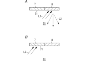
- FIG. 3A is an explanatory diagram of illumination light incident on the light distribution section and illumination light distributed by the light distribution section in the optical system same as above.
- FIG. 3B is an explanatory diagram of power feeding light incident on the photoelectric conversion section in the optical system as described above.
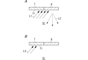
- FIG. 4A is an explanatory diagram of the light distribution angle of illumination light emitted from the light source unit in the optical system according to the second embodiment.
- FIG. 4B is an explanatory diagram of the light distribution angle of power feeding light emitted from the light source unit in the optical system as described above.
- FIG. 3A is an explanatory diagram of illumination light incident on the light distribution section and illumination light distributed by the light distribution section in the optical system same as above.
- FIG. 3B is an explanatory diagram of power feeding light incident on the photoelectric conversion section in the optical system as described above.
- FIG. 5A is an explanatory diagram of the beam size of illumination light emitted from the light source unit in the optical system as described above.
- FIG. 5B is an explanatory diagram of the beam size of power feeding light emitted from the light source unit in the optical system as described above.
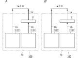
- FIG. 6A is an explanatory diagram of illumination light emitted from a light source unit in the optical system according to the third embodiment.
- FIG. 6B is an explanatory diagram of power feeding light emitted from the light source unit in the optical system as described above.
- FIG. 7 is an explanatory diagram of the operation of the optical system according to the fourth embodiment.
- FIG. 8A is an explanatory diagram of illumination light emitted from the light source unit in the optical system according to the fifth embodiment.
- FIG. 8B is an explanatory diagram of power feeding light emitted from the light source unit in the optical system as described above.
- FIG. 9 is a cross-sectional view of a light distribution section and a photoelectric conversion section in an optical system according to Embodiment 6.
- FIG. 10 is a block diagram of an optical system according to Embodiment 7.
- FIG. 11 is a configuration diagram of an optical system according to Embodiment 8.
- FIG. 12A is an explanatory diagram of illumination light emitted from a light source unit in the optical system according to Embodiment 9.
- FIG. 12B is an explanatory diagram of power feeding light emitted from the light source unit in the optical system as described above.
- Embodiment 1 Below, an optical system 100 according to Embodiment 1 will be described based on FIGS. 1, 2, 3A, and 3B.
- the optical system 100 includes, for example, a light source unit 1 including a laser light source 2, and is a system used for optical wireless power supply and for illuminating a target space S1.
- the target space S1 is, for example, a space within a facility.
- the facility is, for example, an office building.
- the facility may be, for example, a single-family house, an apartment complex, a store, a museum, a hotel, a factory, a stadium, an airport, or the like.
- the optical system 100 includes a light source unit 1 and a photoelectric conversion section 7.
- the light source unit 1 includes a laser light source 2.
- the photoelectric conversion unit 7 can generate photovoltaic force.
- the photoelectric conversion unit 7 generates a photovoltaic force when receiving the power feeding light L3 emitted from the light source unit 1.
- the light source unit 1 is capable of emitting power supply light L3 that is incident on the photoelectric conversion unit 7 and light L1 for illuminating the target space S1.
- the optical system 100 further includes a light distribution section 8.
- the light distribution unit 8 reflects at least a portion of the illumination light L1 to turn at least a portion of the illumination light L1 into illumination light L2 having a light distribution characteristic different from that of the illumination light L1.
- the converted light is distributed to the target space S1.
- the optical system 100 causes the beam-shaped illumination light L1 (for example, beam-shaped white light) emitted from the light source unit 1 to enter the light distribution section 8 as incident light, and the light distribution section 8
- the illumination light L1) is converted into illumination light L2 and output.
- the optical system 100 further includes a holder 10 that holds the photoelectric conversion section 7 and the light distribution section 8.
- the optical system 100 further includes a control section 9 that controls the light source unit 1.
- the control unit 9 has a function of controlling the light source unit 1 so that only the power supply light L3 out of the power supply light L3 and the illumination light L1 is emitted from the light source unit 1, and a function of controlling the light source unit 1 to emit the power supply light L3 from the light source unit 1. It has a function of controlling the light source unit 1 so as to emit only the illumination light L1 out of the light L3 and the illumination light L1.
- the light source unit 1 includes a laser light source 2.
- the laser light source 2 is, for example, a semiconductor laser that emits blue light Lb (see FIG. 2) as laser light. As a result, the laser light source 2 emits blue light Lb.
- the semiconductor laser is, for example, a GaN-based semiconductor laser.
- the peak wavelength of the laser beam is, for example, within the range of 440 nm or more and 480 nm or less.
- the light source unit 1 further includes a wavelength conversion section 3, a lens 4, a mirror 5, and a housing 6 (see FIG. 1).
- the blue light Lb emitted from the laser light source 2 is incident on the wavelength conversion section 3.
- the wavelength converter 3 has a function of converting the blue light Lb into white light Lw including light of a wavelength different from the wavelength of the blue light Lb.
- the wavelength conversion section 3 includes, for example, a translucent material section and phosphor particles.
- the wavelength conversion section 3 is formed of a mixture of a translucent material section and phosphor particles.
- a large number of phosphor particles are present within the translucent material section.
- the material of the transparent material portion is preferably a material with high transmittance to visible light.
- the transparent material is, for example, silicone resin.
- silicone resin includes, for example, silicone resin, modified silicone resin, and the like.
- the wavelength conversion section 3 has phosphor particles as a wavelength conversion element.
- the wavelength conversion element wavelength-converts a portion of the blue light Lb and emits light having a wavelength different from the wavelength of the blue light Lb.
- the phosphor particles for example, yellow phosphor particles that emit yellow light can be used.
- the light (fluorescence) emitted from the yellow phosphor particles preferably has an emission spectrum with a main emission peak wavelength in a wavelength range of 530 nm or more and 580 nm or less, for example.
- the yellow phosphor particles are, for example, Y 3 Al 5 O 12 activated with Ce, but are not limited thereto.
- the white light Lw emitted from the wavelength converter 3 is a mixed color light of blue light Lb and yellow light.
- the wavelength conversion unit 3 does not necessarily include only yellow phosphor particles as a wavelength conversion element, but may include, for example, yellow phosphor particles, yellow-green phosphor particles, green phosphor particles, and red phosphor particles. It may include. That is, the wavelength conversion section 3 may include multiple types of phosphor particles.
- the white light Lw emitted from the wavelength conversion unit 3 is incoherent light.
- the lens 4 is located on the side opposite to the laser light source 2 side when viewed from the wavelength conversion section 3.
- the lens 4 collimates the white light Lw emitted from the wavelength converter 3.
- the mirror 5 is a scanning mirror that can scan the projection direction of the white light Lw emitted from the lens 4.
- the white light Lw reflected by the mirror 5 toward the light distribution unit 8 is illumination light L1
- the mirror 5 reflects the white light Lw toward the light distribution unit 8 (see FIG.
- the white light Lw reflected toward the target is the power feeding light L3.
- the mirror 5 is controlled by a control unit 9, for example.
- the control section 9 controls the mirror 5 so that the white light Lw emitted from the light source unit 1 becomes illumination light L1 directed toward the light distribution section 8 or power feeding light L3 directed toward the photoelectric conversion section 7.
- the mirror 5 is, for example, a MEMS (Micro Electro Mechanical Systems) mirror, but is not limited thereto, and may be, for example, a polygon mirror.
- the housing 6 houses the laser light source 2, the wavelength converter 3, the lens 4, and the mirror 5.
- the material of the emission part that projects the white light Lw into the target space S1 is a translucent material.
- the transparent material is, for example, optical glass.
- the light-transmitting material is preferably a material that has high transmittance to visible light.
- the emitting portion in the housing may be an opening.
- the light source unit 1 is arranged on the back side of the second structure ST2 of the first structure ST1 and the second structure ST2 that partition the target space S1 in the facility.
- the first structure ST1 is the ceiling of the facility, and includes a plurality of first building materials (ceiling materials) 12 facing the target space S1.
- Each of the plurality of first building materials 12 is panel-shaped.
- the second structure ST2 is a wall within the facility, and includes a plurality of second building materials 13 (only one second building material 13 is shown in FIG. 1) facing the target space S1.
- the first structure ST1 is in contact with the target space S1 and defines a boundary between the target space S1 and the attic space.
- the target space S1 is a space under the ceiling.
- the second structure ST2 is in contact with the target space S1 and defines a boundary between the target space S1 and the space behind the wall.
- the light source unit 1 is disposed on the side opposite to the target space S1 in the one second building material 13 among the plurality of second building materials 13, the light source unit 1 is not limited to this. may be placed.
- the one second building material 13 has a window portion 131 through which the power supply light L3 and the illumination light L1 from the light source unit 1 pass.
- the window portion 131 is an opening, but is not limited to this, and may be a translucent member.
- the light source unit 1 is arranged in the second building material 13 at a position higher than a height position from the floor surface F1 that is a predetermined height (for example, 2 m) or more.
- the predetermined height is a height determined such that the light emitting part of the housing 6 in the light source unit 1 is located at a higher position than the height from the floor surface F1 to the eyes of the person 19.
- the light source unit 1 is arranged so that the power supply light L3 and the illumination light L1 propagate upward (that is, obliquely upward) rather than downward in the horizontal direction.
- the photoelectric conversion section 7 is separated from the light source unit 1.
- the photoelectric conversion unit 7 receives the beam-shaped power feeding light L3 emitted from the light source unit 1 into the target space S1, and generates a photovoltaic force.
- the photoelectric conversion unit 7 includes, for example, a solar cell.
- the solar cell is, for example, a Si-based solar cell (a-Si:H/c-Si heterojunction solar cell).
- a Si-based solar cell includes, for example, a substrate having a first main surface and a second main surface opposite to the first main surface.
- the substrate is an n-type single crystal silicon substrate.
- the first major surface of the substrate includes a first textured structure.
- the second major surface of the substrate includes a second textured structure.
- a Si-based solar cell includes a first i-type (intrinsic type) hydrogenated amorphous silicon layer (hereinafter also referred to as a-Si:H layer) formed on a first main surface of a substrate, and a first i-type hydrogenated amorphous silicon layer (hereinafter also referred to as an a-Si:H layer).
- a p-type a-Si:H layer formed on the a-Si:H layer
- a second i-type a-Si:H layer formed on the second main surface of the substrate
- a second i-type a-Si:H layer formed on the second main surface of the substrate.
- a Si-based solar cell includes a first transparent electrode formed on a p-type a-Si:H layer, a first collector electrode formed on the first transparent electrode, and an n-type a-Si:H layer. It includes a second transparent electrode formed above and a second collecting electrode formed on the second transparent electrode.
- the first texture structure and the second texture structure are minute irregularities formed for the purpose of reducing surface reflection loss and increasing light absorption due to the light confinement effect.
- the material of each of the first transparent electrode and the second transparent electrode is transparent conductive oxide.
- the solar cell is not limited to a Si-based solar cell, but may be another type of solar cell.
- the photoelectric conversion section 7 is panel-shaped and has a light incident surface 71 that intersects with the thickness direction of the photoelectric conversion section 7 .
- the photoelectric conversion unit 7 is arranged so that the light incidence surface 71 faces the target space S1.
- the photoelectric conversion unit 7 generates a photovoltaic force when the power feeding light L3 is incident on the light incidence surface 71.
- the light distribution section 8 is separated from the light source unit 1.
- the light distribution section 8 has a function of reflecting the illumination light L1, which is a beam-shaped light emitted from the light source unit 1.
- the light distribution unit 8 converts the illumination light L1 into illumination light L2 having a light distribution characteristic different from that of the illumination light L1, and distributes the illumination light L2 to the target space S1.
- the illumination light L2 has a light distribution characteristic with lower directivity than the illumination light L1.
- the illumination light L2 has a larger spread angle of the luminous flux than the illumination light L1.
- the illumination light L2 has a larger light distribution than the illumination light L1.
- the light distribution unit 8 diffusely reflects the illumination light L1 to convert the illumination light L1 into illumination light L2 that is distributed to the target space S1. It is preferable that the light distribution section 8 has a characteristic of higher diffuse reflectance. Thereby, the light distribution section 8 can have low light absorption and high diffusivity. An example of a suitable color for the light distribution section 8 is white. Further, the light distribution section 8 is preferably made of a member that has no glossy appearance rather than a member that has a glossy appearance, in other words, a member that has a high diffuse reflectance but a low specular reflectance.
- the light distribution section 8 has a first function, a second function, and a third function.
- the first function is to reflect the illumination light L1 toward the target space S1.
- the second function is a function of converting the illumination light L1 into illumination light L2.
- the third function is a function of outputting illumination light L2 toward target space S1.
- the illumination light L2 is light with relatively low coherence (incoherent light) compared to the illumination light L1.
- a table Ta1 used by, for example, a person 19 using the facility is installed below the light distribution section 8 on the floor surface F1.
- the light distribution unit 8 may include a reflection unit that reflects the illumination light L1 toward the target space S1, and a diffusion unit that diffuses the illumination light L1 toward the target space S1.
- the reflective section is, for example, a reflective layer.
- the material of the reflective layer includes, for example, metal.
- the metal is, for example, aluminum or an aluminum alloy.
- the diffusion section is, for example, a transmission type diffusion plate.
- the material of the diffusion part is, for example, polycarbonate, polyester, acrylic, glass or quartz.
- the diffusion section is plate-shaped and has a first main surface on the reflection section side and a second main surface on the opposite side to the reflection section side.
- the diffusing section is arranged such that the second main surface of the diffusing section is in contact with the target space S1.
- the second main surface of the diffusion section has an uneven structure.
- the uneven structure includes a plurality of randomly formed curved surfaces.
- the diffusion section has a plurality of microlenses corresponding to a plurality of curved surfaces. Each of the plurality of curved surfaces functions as a light exit surface of the microlens. Therefore, the diffusion section can also be said to be a microlens array in which a plurality of microlenses are randomly integrated.
- the shape of the uneven structure is determined based on the desired light distribution angle of the illumination light L2.
- the diffusion section diffuses the illumination light L1 reflected by the reflection section by the refraction and diffraction effects of the uneven structure.
- the diffusing section is composed of, for example, a lens diffusing plate (LSD: Light Shaping Diffusers). In the light distribution section 8, the light distribution angle of the illumination light L2 is determined by the uneven structure of the diffusion section.
- (2.4) Holder The holder 10 holds the photoelectric conversion section 7 and the light distribution section 8, as shown in FIG. Here, the photoelectric conversion section 7 and the light distribution section 8 are adjacent to each other.
- the holding body 10 forms, for example, a part of the first structure ST1 facing the target space S1.
- the holder 10 includes a ceiling material 11 facing the target space S1.
- the holding body 10 is arranged, for example, in line with at least one first building material 12 among the plurality of first building materials 12 .
- the ceiling material 11 has a panel shape.
- the ceiling material 11 has a square shape when viewed from the thickness direction of the ceiling material 11, but is not limited to this, and may have a rectangular shape.
- "viewing from the thickness direction of the ceiling material” means, for example, viewing the ceiling material 11 from the target space S1 from the thickness direction of the ceiling material 11.
- the size of the ceiling material 11 is the same as the size of the first building material 12, but may be a different size.
- the ceiling material 11, like the first building material 12, is supported by a grid-shaped support member of the system ceiling that constitutes the ceiling.
- the support member is formed using, for example, a plurality of galvanized steel plates.
- Each of the ceiling material 11 and the first building material 12 is, for example, decorative plywood or decorative board.
- decorative plywood include natural wood decorative plywood and specially processed decorative board.
- specially processed decorative boards include synthetic resin decorative boards, printed plywood, PVC decorative plywood, and paper/fabric overlay plywood.
- the decorative board include MDF (medium density fiberboard), dielite, rock wool board, calcium silicate board, and insulation board.
- the control unit 9 controls the light source unit 1. A function of controlling the light source unit 1 so as to emit only the power supply light L3 out of the power supply light L3 and the illumination light L1 from the light source unit 1, and a function of controlling the light source unit 1 to emit the power supply light L3 and the illumination light L3 from the light source unit 1.
- the light source unit 1 has a function of controlling the light source unit 1 so as to emit only the illumination light L1 out of the light L1.
- the control unit 9 changes the emission direction of the white light Lw by controlling the scanning angle of the mirror 5 of the light source unit 1, thereby emitting the white light Lw as the power supply light L3 or the illumination light L1. Therefore, in the optical system 100, the power feeding light L3 and the illumination light L1 have different emission directions.
- the control unit 9 includes a computer system.
- a computer system mainly consists of a processor and a memory as hardware.
- the function of the control unit 9 is realized by the processor executing a program recorded in the memory of the computer system.
- the program may be pre-recorded in the memory of the computer system, may be provided through a telecommunications line, or may be recorded on a non-transitory storage medium readable by the computer system, such as a memory card, optical disc, hard disk drive, etc. may be provided.
- a processor in a computer system is comprised of one or more electronic circuits including semiconductor integrated circuits (ICs) or large scale integrated circuits (LSIs).
- the integrated circuits such as IC or LSI referred to herein have different names depending on the degree of integration, and include integrated circuits called system LSI, VLSI (Very Large Scale Integration), or ULSI (Ultra Large Scale Integration).
- FPGAs Field-Programmable Gate Arrays
- the plurality of electronic circuits may be integrated into one chip, or may be provided in a distributed manner over a plurality of chips.
- a plurality of chips may be integrated into one device, or may be distributed and provided in a plurality of devices.
- the computer system herein includes a microcontroller having one or more processors and one or more memories. Therefore, the microcontroller is also composed of one or more electronic circuits including semiconductor integrated circuits or large-scale integrated circuits.
- the optical system 100 may further include a power supply unit.
- the power supply unit supplies power to the laser light source 2 and the like.
- the power supply unit includes a drive circuit that drives the laser light source 2.
- the drive circuit is controlled by, for example, the control section 9 described above.
- the control unit 9 controls the drive circuit, thereby making it possible to adjust the light output of the laser light source 2 and adjust the illuminance (brightness) of the illumination light L2.
- the power supply unit is housed in the casing 6 of the light source unit 1, the power supply unit is not limited to this and does not need to be housed in the casing 6.
- a power supply voltage is supplied to the power supply unit from an external power supply via an electric wire.
- the optical system 100 may include a power supply unit including a storage battery that stores electricity using the output of the photoelectric conversion unit 7. Further, the optical system 100 may further include a communication unit that communicates information regarding the state of the storage battery to the control unit 9.
- the control unit 9 for example, while the light source unit 1 is emitting the power feeding light L3, the information received from the communication unit includes information indicating that the storage battery is in a fully charged state. In this case, the emission of the power feeding light L3 may be stopped.
- the optical system 100 emits blue light Lb from the laser light source 2 of the light source unit 1.
- blue light Lb from the laser light source 2 is incident on the wavelength converter 3, and a part of the blue light Lb is converted into yellow light in the wavelength converter 3.
- the blue light Lb emitted from the laser light source 2 is converted into white light Lw by the wavelength converter 3.
- the light source unit 1 collimates the white light Lw emitted from the wavelength converter 3 with the lens 4, reflects the collimated white light Lw with the mirror 5, and projects it into the target space S1.
- the white light Lw emitted from the light source unit 1 passes through the target space S1 and enters the photoelectric conversion section 7 or the light distribution section 8.
- the photoelectric conversion unit 7 generates photovoltaic force when receiving the power feeding light L3.
- the light distribution unit 8 outputs illumination light L2 having light distribution characteristics different from those of the illumination light L1 to the target space S1 by reflecting the illumination light L1.
- the illumination light L2 is incoherent light with low directivity.
- the control unit 9 causes the illumination light L1 to be emitted from the light source unit 1
- the illumination light L1 is transmitted to the light distribution unit 8 of the photoelectric conversion unit 7 and the light distribution unit 8, as shown in FIG. 3A.
- the illumination light L1 is incident on the light distribution section 8 and is converted into illumination light L2.
- the control section 9 causes only the power feeding light L3 to be emitted from the light source unit 1, as shown in FIG.
- the light enters the converter 7, and the photoelectric converter 7 generates a photovoltaic force. Therefore, it is possible to cause the photoelectric conversion unit 7 to generate a photovoltaic force in a state where the target space S1 is not illuminated.
- the illumination light L1 and the power feeding light L3 have different emission directions from the light source unit 1, but the spectrum of the illumination light L1 and the spectrum of the power feeding light L3 are different. are the same, and the beam diameter of the illumination light L1 and the beam diameter of the power feeding light L3 are the same.
- the optical system 100 includes a light source unit 1 including a laser light source 2 and a photoelectric conversion section 7 capable of generating photovoltaic force.
- the photoelectric conversion unit 7 generates a photovoltaic force when receiving the power feeding light L3 emitted from the light source unit 1.
- the light source unit 1 is capable of emitting power supply light L3 that is incident on the photoelectric conversion unit 7 and light L1 for illuminating the target space S1.
- optical wireless power supply and lighting can be performed. More specifically, according to the optical system 100 according to the first embodiment, when the power supply light L3 is emitted from the light source unit 1, photovoltaic force can be generated in the photoelectric conversion section 7. Optical wireless power supply can be performed, and when the light source unit 1 emits the illumination light L1, illumination can be performed.
- the optical system 100 according to the first embodiment further includes a light distribution section 8.
- the light distribution unit 8 reflects at least a portion of the illumination light L1 to turn at least a portion of the illumination light L1 into illumination light L2 having a light distribution characteristic different from that of the illumination light L1.
- the converted light is distributed to the target space S1.
- the optical system 100 according to the first embodiment can provide the illumination light L2 whose distribution is controlled to the target space S1 without using a lighting fixture.
- the optical system 100 according to the first embodiment uses highly directional light (beam-shaped light suitable for long-distance spatial propagation) as the illumination light L1.
- the illumination light L2 converted and distributed by the light distribution unit 8 has relatively lower directivity and coherence than the illumination light L1, and is suitable for illumination.
- the optical system 100 uses the laser light source 2 as a light source, the directivity of the illumination light L1 can be increased, and the light source can be placed farther from the ceiling.
- the optical system 100 according to the first embodiment further includes a holder 10 that holds the photoelectric conversion section 7 and the light distribution section 8.
- the relative positional relationship between the photoelectric conversion section 7 and the light distribution section 8 can be determined by the holder 10.
- the photoelectric conversion section 7 and the light distribution section 8 are adjacent to each other.
- the optical system 100 according to the first embodiment is different from the case where the photoelectric conversion section 7 and the light distribution section 8 are separated and another member is arranged between the photoelectric conversion section 7 and the light distribution section 8. In comparison, it is possible to reduce the angle between the emission direction of the power feeding light L3 and the emission direction of the illumination light L1.
- the holder 10 includes a ceiling material 11 facing the target space S1.
- the light system 100 according to the first embodiment has the advantage that it is easy to illuminate the target space S1 with the illumination light L2, and the illumination by the illumination light L2 is likely to be natural illumination that does not feel strange to the person 19.
- the optical system 100 according to the first embodiment further includes a control section 9 that controls the light source unit 1.
- the control unit 9 has a function of controlling the light source unit 1 so that only the power supply light L3 out of the power supply light L3 and the illumination light L1 is emitted from the light source unit 1, and a function of controlling the light source unit 1 to emit the power supply light L3 from the light source unit 1. It has a function of controlling the light source unit 1 so as to emit only the illumination light L1 out of the light L3 and the illumination light L1.
- the optical system 100 according to the first embodiment can switch between control in which only the light L3 for power supply is emitted from the light source unit 1 and control in which only light L1 for illumination is emitted from the light source unit 1. It becomes possible to perform control to emit only the power feeding light L3 from the light source unit 1 and control to emit only the illumination light L1 from the light source unit 1 at different time zones.
- the power feeding light L3 and the illumination light L1 have different emission directions. Therefore, the optical system 100 according to the first embodiment can emit the power supply light L3 and the illumination light L1 from the light source unit 1 as lights suitable for each.
- the optical system 100 according to the second embodiment includes a light source unit 1a (see FIGS. 4A and 4B) instead of the light source unit 1.
- the basic configuration of the optical system 100 according to the second embodiment is the same as that of the optical system 100 according to the first embodiment, so illustration and description thereof will be omitted.
- the light source unit 1a does not include the mirror 5 in the light source unit 1 (see FIG. 2). Moreover, the light source unit 1a can make the light distribution angle ⁇ 1 of the illumination light L1 and the light distribution angle ⁇ 3 of the power feeding light L3 different from each other.
- the light source unit 1a is configured to be able to change the distance between the wavelength converter 3 and the lens 4a in the direction along the optical axis of the lens 4a. Therefore, in the light source unit 1a, as shown in FIGS. 4A and 4B, by changing the distance between the wavelength converter 3 and the lens 4a in the direction along the optical axis of the lens 4a, the illumination light L1 can be arranged.
- the light angle ⁇ 1 and the light distribution angle ⁇ 3 of the power feeding light L3 can be made different from each other.
- the light source unit 1a includes a movable mechanism that changes the distance between the wavelength conversion section 3 and the lens 4a.
- the light distribution angle ⁇ 3 of the power supply light L3 and the light distribution angle ⁇ 1 of the illumination light L1 are different from each other.
- the light distribution angle ⁇ 1 of the illumination light L1 is larger than the light distribution angle ⁇ 3 of the power feeding light L3.
- the light distribution angle ⁇ 3 of the power supply light L3 is smaller than the light distribution angle ⁇ 1 of the illumination light L1.
- the power feeding light L3 and the illumination light L1 have different light distribution angles. Thereby, the optical system 100 according to the second embodiment can emit the power feeding light L3 and the illumination light L1 from the light source unit 1a as lights suitable for each.
- the illumination light L1 is incident not only on the light distribution section 8 but also on the photoelectric conversion section 7 (the light distribution section 8 and It is now possible to input both the Thereby, in the optical system 100 according to the second embodiment, it becomes possible to cause the photoelectric conversion unit 7 to generate photovoltaic force using a part of the illumination light L1. Therefore, the optical system 100 according to the second embodiment can generate photovoltaic force in the photoelectric conversion unit 7 even when the target space S1 is illuminated with the illumination light L2.
- the light distribution angle ⁇ 1 of the illumination light L1 is larger than the light distribution angle ⁇ 3 of the power feeding light L3, but in a modification of the second embodiment, the light according to the second embodiment
- the light distribution angle ⁇ 3 of the power supply light L3 is larger than the light distribution angle ⁇ 1 of the illumination light L1.
- the power feeding light L3 enter not only the photoelectric conversion unit 7 but also the light distribution unit 8 (inject the light L3 into both the photoelectric conversion unit 7 and the light distribution unit 8).
- the modified example of the second embodiment it becomes possible to generate the illumination light L2 using a part of the power feeding light L3.
- the optical system 100 according to the third embodiment includes a light source unit 1b (see FIGS. 6A and 6B) instead of the light source unit 1.
- the basic configuration of the optical system 100 according to the third embodiment is the same as that of the optical system 100 according to the first embodiment, so illustration and description thereof will be omitted.
- the light source unit 1b includes a plurality (three) of laser light sources 2.
- the three laser light sources 2 include a red semiconductor laser 2R (hereinafter also referred to as laser light source 2R) that emits red light Lr, a green semiconductor laser 2G (hereinafter also referred to as laser light source 2G) that emits green light Lg, and a blue semiconductor laser 2R (hereinafter also referred to as laser light source 2G) that emits green light Lg.
- a blue semiconductor laser 2B (hereinafter also referred to as a laser light source 2B) that emits light Lb is included.
- red light Lr, green light Lg, and blue light Lb are emitted from a housing housing three laser light sources 2.
- the light emitted from the light emitting section of the light source unit 1b is white light Lw that is a mixture of red light Lr, green light Lg, and blue light Lb.
- the light source unit 1b further includes three mirrors 25R, 25G, and 25B that correspond one-to-one to the three laser light sources 2R, 2G, and 2B.
- the housing accommodates three laser light sources 2R, 2G, 2B and three mirrors 25R, 25G, 25B.
- Mirror 25B reflects blue light Lb from laser light source 2B toward mirror 25G.
- Mirror 25G is a dichroic mirror that reflects green light Lg from laser light source 2G toward mirror 25R and transmits blue light Lb from mirror 25B.
- the mirror 25R is a dichroic mirror that transmits the red light Lr from the laser light source 2R and reflects the blue light Lb and green light Lg from the mirror 25G.
- the three laser light sources 2 and the light emitting part of the housing are optically coupled by three mirrors 25R, 25G, and 25B.
- the light source unit 1b may have a collimating lens that collimates the white light Lw, and may be configured to emit the white light Lw collimated by the collimating lens to the target space S1.
- the optical system 100 according to the third embodiment includes three drive circuits that correspond one-to-one to the three laser light sources 2R, 2G, and 2B.
- the control unit 9 (see FIG. 1) individually controls the three drive circuits.
- the optical system 100 according to the third embodiment it becomes possible to control the output ratio of the three laser light sources 2R, 2G, and 2B. Therefore, in the optical system 100 according to the third embodiment, it is possible to make the spectrum of the power feeding light L3 and the spectrum of the illumination light L1 different from each other.
- the power supply light L3 shown in FIG. 6B compared to the illumination light L1 shown in FIG.
- the spectrum of the light L3 for use as an illumination light and the spectrum of the light L1 for illumination are made different.
- the magnitude of the light output of the blue light Lb, the green light Lg, and the red light Lr is schematically shown depending on the magnitude of the line width of the blue light Lb, the green light Lg, and the red light Lr. It is preferable that the light having a wavelength that increases the optical output in the power feeding light L3 is included in a wavelength range in which the photoelectric conversion unit 7 has high efficiency.
- the optical system 100 according to the third embodiment makes it possible to make the light incident on both sides. Thereby, in the optical system 100 according to the third embodiment, it becomes possible to cause the photoelectric conversion unit 7 to generate photovoltaic force using a part of the illumination light L1. Therefore, the optical system 100 according to the third embodiment can generate a photovoltaic force in the photoelectric conversion unit 7 even when the target space S1 is illuminated with the illumination light L2.
- the power feeding light L3 is also made incident on both the photoelectric conversion section 7 and the light distribution section 8.
- the optical system 100 according to the third embodiment may further include a mirror 5 (see FIG. 2) that changes the emission direction of the white light Lw.
- the light source unit 1b includes three laser light sources 2, the invention is not limited thereto, and may include four or more laser light sources 2 that emit light of different colors. Thereby, in the optical system 100, it becomes possible to improve the color rendering properties of the light (white light Lw) emitted from the light emitting section of the light source unit 1b.
- the optical system 100 according to the fourth embodiment includes a light source unit 1c (see FIGS. 8A and 8B) instead of the light source unit 1.
- the basic configuration of the optical system 100 according to the fourth embodiment is the same as that of the optical system 100 according to the first embodiment, so illustration and description thereof will be omitted.
- the light source unit 1c includes two laser light sources 2, as shown in FIGS. 8A and 8B.
- the wavelength converter 3 is arranged on the optical axis of the first laser light source 21 of the two laser light sources 2, whereas the wavelength converter 3 is arranged on the optical axis of the second laser light source 22.
- the converter 3 is not arranged.
- Each of the first laser light source 21 and the second laser light source 22 emits blue light Lb.
- the wavelength converter 3 converts the blue light Lb from the first laser light source 21 into yellow light Ly and emits the yellow light Ly.
- the light source unit 1c has a collimating lens that collimates the blue light Lb that does not pass through the wavelength converter 3 and the yellow light emitted from the wavelength converter 3, and emits the white light Lw collimated by the collimator lens to the target space S1. is configured to do so.
- the optical system 100 according to the fourth embodiment includes two drive circuits that correspond one-to-one to the two laser light sources 2.
- the control unit 9 (see FIG. 1) individually controls the two drive circuits.
- the optical system 100 according to the fourth embodiment it becomes possible to control the output ratio of the two laser light sources 2.
- the optical system 100 according to the fourth embodiment it is possible to make the spectrum of the power feeding light L3 and the spectrum of the illumination light L1 different from each other.
- the power feeding light L3 shown in FIG. 8B compared to the illumination light L1 shown in FIG. 8A, the output of the first laser light source 21 is made smaller and the output of the second laser light source 22 is made larger.
- the spectrum of the light L3 and the spectrum of the illumination light L1 are made different.
- the magnitude of the light output of the blue light Lb and the yellow light Ly is schematically shown depending on the magnitude of the line width of the blue light Lb and the yellow light Ly. It is preferable that the light having a wavelength that increases the optical output in the power feeding light L3 is included in a wavelength range in which the photoelectric conversion unit 7 has high efficiency.
- the illumination light L1 is incident not only on the light distribution section 8 but also on the photoelectric conversion section 7 (the light distribution section 8 and the photoelectric conversion section 7).
- the optical system 100 according to the fourth embodiment it becomes possible to cause the photoelectric conversion unit 7 to generate photovoltaic force using a part of the illumination light L1. Therefore, the optical system 100 according to the fourth embodiment can generate photovoltaic force in the photoelectric conversion unit 7 even when the target space S1 is illuminated with the illumination light L2.
- the optical system 100 according to the fourth embodiment may further include a mirror 5 (see FIG. 2) that changes the emission direction of the white light Lw.
- the optical system 100 according to the fifth embodiment is different from the optical system 100 according to the first embodiment in that, as shown in FIG. 9, the photoelectric conversion section 7 and the light distribution section 8 are stacked.
- the basic configuration of the optical system 100 according to the fifth embodiment is the same as that of the optical system 100 according to the first embodiment, so illustration and description will be omitted.
- the light distribution section 8 overlaps the photoelectric conversion section 7.
- the light distribution section 8 is arranged on the light incidence surface 71 of the photoelectric conversion section 7 .
- the light distribution section 8 and the photoelectric conversion section 7 are arranged such that the light distribution section 8 of the light distribution section 8 and the photoelectric conversion section 7 is in contact with the target space S1.
- the power feeding light L3 enters the photoelectric conversion unit 7 through the light distribution unit 8. That is, in the optical system 100 according to the fifth embodiment, only a part of the illumination light L1 that has entered the light incidence surface 81 of the light distribution section 8 is diffusely reflected by the light distribution section 8 and is transmitted to the target space S1 as illumination light L2. At least a portion of the remaining illumination light L1 emitted from the light distribution unit 8 and incident on the light incidence surface 81 of the light distribution unit 8 passes through the light distribution unit 8 and reaches the photoelectric conversion unit 7 as power supply light L3. The reflectance of the light distribution section 8 is determined so that.
- the optical system 100 according to the fifth embodiment can make the emission direction of the power feeding light L3 the same as the emission direction of the illumination light L1. Moreover, the optical system 100 according to the fifth embodiment can reduce the area occupied by the members including the light distribution section 8 and the photoelectric conversion section 7 when viewed from the target space S1, and improves the design. becomes possible.
- the optical system 100 according to the sixth embodiment differs from the optical system 100 according to the first embodiment in that, as shown in FIG. 10, the optical system 100 includes a sensor 20 that receives power supply from the photoelectric conversion unit 7.
- the same components as those in the optical system 100 according to Embodiment 1 are given the same reference numerals, and the description thereof will be omitted.
- the optical system 100 includes a light source unit 1 , a photoelectric conversion section 7 , a light distribution section 8 , a first control section 9 that is a control section 9 that controls the light source unit 1 , and a secondary battery 15 . , a bidirectional converter 14 that performs power conversion between the photoelectric conversion unit 7 and the secondary battery 15, a transmitter 17, a receiver 18, a sensor 20, and a second control unit 16.
- the sensor 20 is, for example, a human sensor that detects a person 19 (see FIG. 1) in the target space S1 (see FIG. 1), but is not limited thereto. It may also be a sensing sensor.
- the second control unit 16 causes the transmitter 17 to transmit a control signal based on the detection result of the sensor 20.
- the receiver 18 receives the control signal from the transmitter 17 and transmits it to the first controller 9. Thereby, the first control section 9 can control the light source unit 1 according to the detection result of the sensor 20.
- the optical system 100 according to the sixth embodiment does not need to supply power from the outside via wires (electric wires) to the sensor 20 installed on the ceiling of the facility, and does not need to be provided with a battery such as a primary battery that needs to be replaced.
- the advantage is that there is no.
- the photovoltaic force generated in the photoelectric conversion unit 7 may be directly supplied to the sensor 20 without going through the secondary battery 15.
- the optical system 100 according to the seventh embodiment includes a holder 10a (see FIG. 11) instead of the holder 10 (see FIG. 1) in the optical system 100 according to the first embodiment.
- the holding body 10a is a moving body 101.
- the basic configuration of the optical system 100 according to the seventh embodiment is the same as that of the optical system 100 according to the first embodiment, so illustration and description thereof will be omitted.
- the moving object 101 that constitutes the holding body 10a is, for example, a type of flying object, a drone.
- the drone operates by remote control using a management terminal.
- the management terminal is, for example, a personal computer or a server.
- the light source unit 1 emits the power feeding light L3 toward the photoelectric conversion unit 7 when the moving body 101 is stopped.
- the electromotive force generated by the photoelectric conversion unit 7 is used, for example, to charge a secondary battery for the power source of the moving body 101.
- the light source unit 1 emits power feeding light L3 toward the photoelectric conversion unit 7 while the moving object 101 is moving (during the flight of the drone), and the moving object 101 A secondary battery for power supply may be charged.
- the optical system 100 according to the seventh embodiment by supplying power to the flying drone while illuminating the drone with the illumination light L2, it is possible to lengthen the flight time of the drone that performs illumination.
- the moving body 101 includes a main body 102, a plurality of (for example, four) propellers 110, a plurality of (for example, four) drive units (for example, motors) that drive the plurality of propellers 110, and a plurality of drive units. , a plurality of (for example, four) leg sections 111 , a holding arm 112 holding the photoelectric conversion section 7 , and a holding arm 113 holding the light distribution section 8 . are doing. Furthermore, the mobile object 101 further includes a camera, a GPS sensor, a gyro sensor, an acceleration sensor, an electronic compass, a wireless communication unit, and the like.
- the optical system 100 enables optical wireless power supply to the moving object 101, and also provides illumination to the light distribution unit 8 after moving the moving object 101 to a desired position or while moving the moving object 101. By allowing the light L1 to enter, it becomes possible to change the area illuminated by the illumination light L2.
- the optical system 100 according to the eighth embodiment includes a light source unit 1d instead of the light source unit 1 (see FIGS. 1 and 2) in the optical system 100 according to the first embodiment. This is different from the optical system 100 according to the first embodiment.
- the same components as those in the optical system 100 according to Embodiment 1 are given the same reference numerals, and the description thereof will be omitted.
- the light source unit 1d does not have the mirror 5 in the light source unit 1 (see FIG. 2).
- the light source unit 1d also includes an optical fiber 120 that propagates the white light Lw (see FIG. 2) collimated by the lens 4, and an output unit 130 that outputs the white light Lw propagated by the optical fiber 120 to the target space S1. , further has.
- the emission unit 130 has a function of emitting illumination light L1 as illumination light L2, as shown in FIG. 12A, and a function of emitting power supply light L3 to the target space S1, as shown in FIG. 12B.
- the output unit 130 includes a lens that faces the light output surface of the optical fiber 120, and by changing the distance between the light output surface of the optical fiber 120 and the lens, the light distribution angle ⁇ 1 of the illumination light L1 can be adjusted. and the light distribution angle ⁇ 3 of the power feeding light L3 can be made different, and it is also possible to set the light distribution angle ⁇ 1 of the illumination light L1 to the light distribution angle ⁇ 2 of the illumination light L2.
- the photoelectric conversion unit 7 (FIG. 12B) is arranged, for example, on the table Ta1 used by the person 19 using the facility when the person 19 is not using it.
- the output unit 130 includes a mirror that reflects the light emitted from the light output surface of the optical fiber 120, and by controlling the scanning angle of the mirror, the output direction of the illumination light L2 and the power supply light L3 are adjusted. It is possible to make the emission direction different from the emission direction.
- the light source unit 1d has a function of emitting power supply light L3 to the target space S1, and a function of emitting the illumination light L1 to the target space S1 as illumination light L2. have Thereby, the optical system 100 according to the eighth embodiment can directly illuminate the target space S1 with the light source unit 1d.
- Embodiments 1 to 8 described above are only one of various embodiments of the present disclosure. Embodiments 1 to 8 described above can be modified in various ways depending on the design, etc., as long as the objective of the present disclosure can be achieved.
- the holder 10 is not limited to including the ceiling material 11, and may include, for example, a beam.
- the laser light source 2 is not limited to a semiconductor laser that emits blue laser light, but may be a semiconductor laser that emits purple laser light, for example.
- the wavelength converter 3 preferably includes blue phosphor particles, yellow phosphor particles, green phosphor particles, and red phosphor particles. Blue phosphor particles are excited by, for example, violet laser light and emit blue light. The yellow phosphor particles are excited by, for example, violet laser light and emit yellow light. The green phosphor particles are excited by, for example, violet laser light and emit green light. Red phosphor particles are excited by, for example, violet laser light and emit red light.
- the shortest distance between the photoelectric conversion section 7 and the light source unit 1 is shorter than the shortest distance between the light distribution section 8 and the light source unit 1; however, the shortest distance is not limited to this. do not have.
- the shortest distance between the light distribution section 8 and the light source unit 1 may be shorter than the shortest distance between the photoelectric conversion section 7 and the light source unit 1, or the shortest distance between the light distribution section 8 and the light source unit 1 may be shorter than the shortest distance between the photoelectric conversion section 7 and the light source unit 1.
- the shortest distance between them may be the same as the shortest distance between the photoelectric conversion section 7 and the light source unit 1.
- control unit 9 may control the light source unit 1 according to a preset schedule.
- the optical system (100) includes a light source unit (1; 1a; 1b; 1c; 1d) including a laser light source (2), a photoelectric conversion unit (7) capable of generating photovoltaic force, Equipped with The photoelectric conversion unit (7) generates a photovoltaic force when receiving the power feeding light (L3) emitted from the light source unit (1; 1a; 1b; 1c; 1d).
- the light source unit (1; 1a; 1b; 1c; 1d) emits power supply light (L3) that is incident on the photoelectric conversion unit (7) and light (L1) for illuminating the target space (S1). It is possible.
- the optical system (100) according to the first aspect can perform optical wireless power supply and illumination.
- the optical system 100 according to the second aspect further includes a light distribution section (8) in the first aspect.
- the light distribution section (8) reflects at least a portion of the illumination light (L1) so that at least a portion of the illumination light (L1) has a light distribution characteristic different from that of the illumination light (L1). It is converted into illumination light (L2) having a light distribution characteristic and distributed to the target space (S1).
- the light system (100) can provide illumination light (L2) whose distribution is controlled to the target space (S1) without using a lighting fixture.
- the optical system (100) according to the third aspect further includes a holder (10; 10a) that holds the photoelectric conversion section (7) and the light distribution section (8) in the second aspect.
- the optical system (100) allows the relative positional relationship between the photoelectric conversion section (7) and the light distribution section (8) to be determined by the holder (10; 10a).
- the photoelectric conversion section (7) and the light distribution section (8) are adjacent to each other in the third aspect.
- the optical system (100) according to the fourth aspect is such that the photoelectric conversion section (7) and the light distribution section (8) are separated from each other, and the photoelectric conversion section (7) and the light distribution section (8) are Compared to the case where the members are arranged, it is possible to make the angle between the emission direction of the power feeding light (L3) and the emission direction of the illumination light (L1) smaller.
- the holder (10) in the optical system (100) according to the fifth aspect, includes a ceiling material (11) facing the target space (S1).
- the light system (100) according to the fifth aspect has the advantage that it is easy to illuminate the target space (S1) with the illumination light (L2), and it is easy to provide natural lighting that does not feel strange to the person (19).
- the holding body (10a) is the moving body (101) in the third or fourth aspect.
- the optical system (100) according to the sixth aspect enables optical wireless power supply to the moving object (101), and also allows changing the illumination area by the illumination light (L2) by moving the moving object (101). It becomes possible.
- the light distribution section (8) overlaps the photoelectric conversion section (7) in the second aspect.
- the power supply light (L3) enters the photoelectric conversion unit (7) through the light distribution unit (8).
- the optical system (100) according to the seventh aspect can make the emission direction of the power feeding light (L3) the same as the emission direction of the illumination light (L1). Furthermore, the optical system (100) according to the seventh aspect has the advantage of reducing the area occupied by the members including the light distribution section (8) and the photoelectric conversion section (7) when viewed from the target space (S1). This makes it possible to improve the design quality.
- the control unit (9) controls the light source unit (1) so that only the power supply light (L3) out of the power supply light (L3) and the illumination light (L1) is emitted from the light source unit (1). and controlling the light source unit (1) so that only the illumination light (L1) out of the power supply light (L3) and the illumination light (L1) is emitted from the light source unit (1). It has a function.
- the light system (100) includes control for emitting only light for power supply (L3) from the light source unit (1), and control for emitting only light for illumination (L1) from the light source unit (1). It is now possible to switch between the control to emit only the power supply light (L3) from the light source unit (1) and the control to emit only the illumination light (L1) from the light source unit (1). This can be done at different times.
- the power feeding light (L3) and the illumination light (L1) have a spectrum, an emission direction, and an arrangement. At least one of the light angles is different from each other.
- the optical system (100) according to the ninth aspect is capable of emitting power supply light (L3) and illumination light (L1) from the light source unit (1) as lights suitable for each.
- the power feeding light (L3) and the illumination light (L1) are the same light.
- the light system (100) aims to reduce the number of parts of the light source unit (1) compared to the case where the power supply light (L3) and the illumination light (L1) are different lights. becomes possible.
- the light source unit (1d) has a function of emitting power supply light (L3) to the target space (S1), and an illumination light (L3). L1) into the target space (S1) as illumination light (L2).
- the light system (100) according to the eleventh aspect can directly illuminate the target space (S1) with the light source unit (1d).
- the optical system (100) according to the twelfth aspect, in any one of the first to eleventh aspects, further includes a sensor (20) that receives power supply from the photoelectric conversion section (7).
- the optical system (100) can use the photovoltaic force generated in the photoelectric conversion section (7) as a power source for the sensor (20).
Landscapes
- Engineering & Computer Science (AREA)
- General Engineering & Computer Science (AREA)
- Physics & Mathematics (AREA)
- Optics & Photonics (AREA)
- Non-Portable Lighting Devices Or Systems Thereof (AREA)
Priority Applications (3)
| Application Number | Priority Date | Filing Date | Title |
|---|---|---|---|
| JP2024506051A JP7804953B2 (ja) | 2022-03-11 | 2023-02-22 | 光システム |
| CN202380020657.1A CN118661056A (zh) | 2022-03-11 | 2023-02-22 | 光系统 |
| US18/844,853 US12410896B2 (en) | 2022-03-11 | 2023-02-22 | Light system |
Applications Claiming Priority (2)
| Application Number | Priority Date | Filing Date | Title |
|---|---|---|---|
| JP2022038587 | 2022-03-11 | ||
| JP2022-038587 | 2022-03-11 |
Publications (1)
| Publication Number | Publication Date |
|---|---|
| WO2023171386A1 true WO2023171386A1 (ja) | 2023-09-14 |
Family
ID=87934982
Family Applications (1)
| Application Number | Title | Priority Date | Filing Date |
|---|---|---|---|
| PCT/JP2023/006420 Ceased WO2023171386A1 (ja) | 2022-03-11 | 2023-02-22 | 光システム |
Country Status (4)
| Country | Link |
|---|---|
| US (1) | US12410896B2 (https=) |
| JP (1) | JP7804953B2 (https=) |
| CN (1) | CN118661056A (https=) |
| WO (1) | WO2023171386A1 (https=) |
Citations (4)
| Publication number | Priority date | Publication date | Assignee | Title |
|---|---|---|---|---|
| JP2019009062A (ja) * | 2017-06-28 | 2019-01-17 | 国立大学法人大阪大学 | 照明装置 |
| JP2019016510A (ja) * | 2017-07-06 | 2019-01-31 | 岩崎電気株式会社 | 照明システム |
| JP2020099122A (ja) * | 2018-12-17 | 2020-06-25 | パナソニックIpマネジメント株式会社 | 光無線給電システム |
| WO2021200128A1 (ja) * | 2020-03-31 | 2021-10-07 | パナソニックIpマネジメント株式会社 | 建材、光照射システム、及び照明システム |
Family Cites Families (1)
| Publication number | Priority date | Publication date | Assignee | Title |
|---|---|---|---|---|
| WO2021255981A1 (ja) * | 2020-06-17 | 2021-12-23 | シャープ株式会社 | 照射装置および無線給電装置 |
-
2023
- 2023-02-22 JP JP2024506051A patent/JP7804953B2/ja active Active
- 2023-02-22 US US18/844,853 patent/US12410896B2/en active Active
- 2023-02-22 WO PCT/JP2023/006420 patent/WO2023171386A1/ja not_active Ceased
- 2023-02-22 CN CN202380020657.1A patent/CN118661056A/zh active Pending
Patent Citations (4)
| Publication number | Priority date | Publication date | Assignee | Title |
|---|---|---|---|---|
| JP2019009062A (ja) * | 2017-06-28 | 2019-01-17 | 国立大学法人大阪大学 | 照明装置 |
| JP2019016510A (ja) * | 2017-07-06 | 2019-01-31 | 岩崎電気株式会社 | 照明システム |
| JP2020099122A (ja) * | 2018-12-17 | 2020-06-25 | パナソニックIpマネジメント株式会社 | 光無線給電システム |
| WO2021200128A1 (ja) * | 2020-03-31 | 2021-10-07 | パナソニックIpマネジメント株式会社 | 建材、光照射システム、及び照明システム |
Also Published As
| Publication number | Publication date |
|---|---|
| US12410896B2 (en) | 2025-09-09 |
| JPWO2023171386A1 (https=) | 2023-09-14 |
| JP7804953B2 (ja) | 2026-01-23 |
| US20250189089A1 (en) | 2025-06-12 |
| CN118661056A (zh) | 2024-09-17 |
Similar Documents
| Publication | Publication Date | Title |
|---|---|---|
| KR102255641B1 (ko) | 대면적 광원 및 대면적 조명기구 | |
| KR102536758B1 (ko) | 인공 스카이라이트 및 방법 | |
| KR101849120B1 (ko) | 조명 시스템 | |
| CN110382948B (zh) | 基于阳光的太阳模拟照明 | |
| RU2606969C2 (ru) | Осветительный элемент, осветительная система и осветительный прибор, обеспечивающий внешний вид светового люка | |
| CN102884641B (zh) | 具有可切换的照明/反射的光伏电池装置 | |
| JP5608752B2 (ja) | 発光装置 | |
| US10151442B2 (en) | Light environment producing apparatus | |
| JP2018060624A (ja) | 照明装置 | |
| JP6924514B2 (ja) | 大面積光源および大面積照明器具 | |
| JP2005072570A (ja) | 太陽電池を利用した発光ブロック | |
| JP6621148B2 (ja) | 表示装置 | |
| JP4572754B2 (ja) | 電力伝送システム及び方法 | |
| JP2010251213A (ja) | 発光モジュールおよび照明装置 | |
| JP7804953B2 (ja) | 光システム | |
| CN208983064U (zh) | 照明装置 | |
| US20140192528A1 (en) | Light-Emitting Device and Luminaire | |
| US12292166B2 (en) | Lighting system | |
| JP7660325B2 (ja) | 照明システム | |
| CN115398141A (zh) | 建筑构件、光照射系统和照明系统 | |
| JP2023149064A (ja) | 灯具及び照明システム | |
| WO2019043872A1 (ja) | 照明装置 | |
| CN102456815A (zh) | 全周光发光二极管模块 |
Legal Events
| Date | Code | Title | Description |
|---|---|---|---|
| 121 | Ep: the epo has been informed by wipo that ep was designated in this application |
Ref document number: 23766564 Country of ref document: EP Kind code of ref document: A1 |
|
| WWE | Wipo information: entry into national phase |
Ref document number: 202380020657.1 Country of ref document: CN |
|
| ENP | Entry into the national phase |
Ref document number: 2024506051 Country of ref document: JP Kind code of ref document: A |
|
| WWE | Wipo information: entry into national phase |
Ref document number: 18844853 Country of ref document: US |
|
| NENP | Non-entry into the national phase |
Ref country code: DE |
|
| 122 | Ep: pct application non-entry in european phase |
Ref document number: 23766564 Country of ref document: EP Kind code of ref document: A1 |
|
| WWP | Wipo information: published in national office |
Ref document number: 18844853 Country of ref document: US |
|
| WWG | Wipo information: grant in national office |
Ref document number: 18844853 Country of ref document: US |