WO2023170791A1 - 情報処理装置、支援システム、支援方法、及び支援プログラム - Google Patents
情報処理装置、支援システム、支援方法、及び支援プログラム Download PDFInfo
- Publication number
- WO2023170791A1 WO2023170791A1 PCT/JP2022/010021 JP2022010021W WO2023170791A1 WO 2023170791 A1 WO2023170791 A1 WO 2023170791A1 JP 2022010021 W JP2022010021 W JP 2022010021W WO 2023170791 A1 WO2023170791 A1 WO 2023170791A1
- Authority
- WO
- WIPO (PCT)
- Prior art keywords
- board
- inspection target
- name
- unit
- image
- Prior art date
- Legal status (The legal status is an assumption and is not a legal conclusion. Google has not performed a legal analysis and makes no representation as to the accuracy of the status listed.)
- Ceased
Links
Images





Classifications
-
- H—ELECTRICITY
- H02—GENERATION; CONVERSION OR DISTRIBUTION OF ELECTRIC POWER
- H02B—BOARDS, SUBSTATIONS OR SWITCHING ARRANGEMENTS FOR THE SUPPLY OR DISTRIBUTION OF ELECTRIC POWER
- H02B3/00—Apparatus specially adapted for the manufacture, assembly, or maintenance of boards or switchgear
-
- G—PHYSICS
- G06—COMPUTING OR CALCULATING; COUNTING
- G06V—IMAGE OR VIDEO RECOGNITION OR UNDERSTANDING
- G06V20/00—Scenes; Scene-specific elements
- G06V20/60—Type of objects
- G06V20/62—Text, e.g. of license plates, overlay texts or captions on TV images
- G06V20/63—Scene text, e.g. street names
-
- G—PHYSICS
- G05—CONTROLLING; REGULATING
- G05B—CONTROL OR REGULATING SYSTEMS IN GENERAL; FUNCTIONAL ELEMENTS OF SUCH SYSTEMS; MONITORING OR TESTING ARRANGEMENTS FOR SUCH SYSTEMS OR ELEMENTS
- G05B23/00—Testing or monitoring of control systems or parts thereof
- G05B23/02—Electric testing or monitoring
-
- G—PHYSICS
- G06—COMPUTING OR CALCULATING; COUNTING
- G06F—ELECTRIC DIGITAL DATA PROCESSING
- G06F3/00—Input arrangements for transferring data to be processed into a form capable of being handled by the computer; Output arrangements for transferring data from processing unit to output unit, e.g. interface arrangements
- G06F3/002—Specific input/output arrangements not covered by G06F3/01 - G06F3/16
- G06F3/005—Input arrangements through a video camera
-
- G—PHYSICS
- G06—COMPUTING OR CALCULATING; COUNTING
- G06F—ELECTRIC DIGITAL DATA PROCESSING
- G06F3/00—Input arrangements for transferring data to be processed into a form capable of being handled by the computer; Output arrangements for transferring data from processing unit to output unit, e.g. interface arrangements
- G06F3/14—Digital output to display device ; Cooperation and interconnection of the display device with other functional units
-
- G—PHYSICS
- G06—COMPUTING OR CALCULATING; COUNTING
- G06T—IMAGE DATA PROCESSING OR GENERATION, IN GENERAL
- G06T7/00—Image analysis
-
- G—PHYSICS
- G06—COMPUTING OR CALCULATING; COUNTING
- G06T—IMAGE DATA PROCESSING OR GENERATION, IN GENERAL
- G06T7/00—Image analysis
- G06T7/0002—Inspection of images, e.g. flaw detection
-
- G—PHYSICS
- G06—COMPUTING OR CALCULATING; COUNTING
- G06T—IMAGE DATA PROCESSING OR GENERATION, IN GENERAL
- G06T7/00—Image analysis
- G06T7/70—Determining position or orientation of objects or cameras
-
- G—PHYSICS
- G06—COMPUTING OR CALCULATING; COUNTING
- G06V—IMAGE OR VIDEO RECOGNITION OR UNDERSTANDING
- G06V30/00—Character recognition; Recognising digital ink; Document-oriented image-based pattern recognition
- G06V30/10—Character recognition
-
- G—PHYSICS
- G06—COMPUTING OR CALCULATING; COUNTING
- G06V—IMAGE OR VIDEO RECOGNITION OR UNDERSTANDING
- G06V2201/00—Indexing scheme relating to image or video recognition or understanding
- G06V2201/07—Target detection
Definitions
- the present disclosure relates to an information processing device, a support system, a support method, and a support program.
- Control panels, switchboards, distribution boards, etc. are installed in facilities such as power plants. These panels are inspected on a daily or periodic basis. These panels include meters, etc. Meters and other equipment are subject to inspection. Here, a technique for extracting the display contents of a meter has been proposed (see Patent Document 1).
- the contents of the inspection target are extracted.
- this technology does not know which board contains the contents to be inspected. Therefore, it is necessary for the inspector to manually associate the inspection target with the panel that includes the inspection target. For example, an inspector uses a computer to perform association work. Having the inspector perform the work increases the burden on the inspector.
- the purpose of this disclosure is to relieve the burden.
- the information processing device includes an acquisition unit that acquires an image showing the board including the board name and the inspection target, and position information that is information indicating a correspondence relationship between the board name, the position of the inspection target, and the name of the inspection target. and a detection unit that detects the board based on the image, detects the name of the board from within an image area showing the board, and detects the position of the inspection target based on the image area showing the board. and an association unit that associates the board and the inspection target based on the name of the board, the position of the inspection target, and the position information.
- the burden can be reduced.
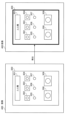
- FIG. 1 is a diagram showing a support system according to Embodiment 1.
- FIG. FIG. 2 is a diagram showing hardware included in the information processing apparatus according to the first embodiment.
- FIG. 2 is a block diagram showing functions of the information processing device according to the first embodiment.
- FIG. 3 is a diagram showing an example of a position table according to the first embodiment.
- FIG. 3 is a diagram illustrating an example of detecting a board according to the first embodiment.
- 3 is a diagram illustrating an example of an association image according to the first embodiment;
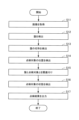
- FIG. 3 is a flowchart illustrating an example of processing executed by the information processing apparatus according to the first embodiment.
- FIG. 3 is a diagram showing a support system according to a second embodiment.
- FIG. 2 is a block diagram showing functions of an information processing device according to a second embodiment.
- FIG. 3 is a block diagram showing functions of an information processing device according to a third embodiment.
- FIG. 9 is a diagram showing an example of a case where inspection results according to Embodiment 4 are displayed.
- FIG. 7 is a block diagram showing functions of a mobile terminal according to a fifth embodiment.
- FIG. 1 is a diagram showing a support system according to the first embodiment.
- the support system includes an information processing device 100 and a mobile terminal 200.
- Information processing device 100 and mobile terminal 200 are connected via a network.
- the information processing device 100 is a device that executes a support method.
- Mobile terminal 200 is a device used by an inspector.
- the mobile terminal 200 is a smartphone, a tablet terminal, or an HMD (Head Mounted Display).
- Mobile terminal 200 has an imaging unit.
- FIG. 1 shows a board 300.
- the panel 300 is a control panel, a switchboard, a distribution panel, or the like.
- Panel 300 includes a nameplate 301, switches 302-304, lamps 305-307, and meters 308, 309.
- the nameplate 301 has the name of the board 300 written thereon. Switches 302 to 304, lamps 305 to 307, and meters 308 and 309 are to be inspected.
- the inspector photographs the board 300 using the mobile terminal 200. Then, the mobile terminal 200 transmits an image showing the board 300 to the information processing device 100.
- the information processing device 100 automatically associates the board 300 with the inspection target based on the image. This eliminates the need for the inspector to manually associate the inspection target with the panel that includes the inspection target. Therefore, the information processing device 100 can reduce the burden on the inspector.
- the information processing device 100 will be described in detail below.
- FIG. 2 is a diagram showing hardware included in the information processing apparatus according to the first embodiment.
- the information processing device 100 includes a processor 101, a volatile storage device 102, and a nonvolatile storage device 103.
- the processor 101 controls the entire information processing device 100.
- the processor 101 is a CPU (Central Processing Unit), an FPGA (Field Programmable Gate Array), or the like.
- Processor 101 may be a multiprocessor.
- the information processing device 100 may include a processing circuit.
- the volatile storage device 102 is the main storage device of the information processing device 100.
- the volatile storage device 102 is a RAM (Random Access Memory).
- the nonvolatile storage device 103 is an auxiliary storage device of the information processing device 100.
- the nonvolatile storage device 103 is a HDD (Hard Disk Drive) or an SSD (Solid State Drive).
- FIG. 3 is a block diagram showing the functions of the information processing apparatus according to the first embodiment.
- the information processing device 100 includes a storage section 110, an acquisition section 120, a detection section 130, an association section 140, a state detection section 150, and an output section 160.
- the state detection section 150 may also be called an inspection section.
- the storage unit 110 may be realized as a storage area secured in the volatile storage device 102 or the nonvolatile storage device 103.
- Part or all of the acquisition section 120, the detection section 130, the association section 140, the state detection section 150, and the output section 160 may be realized by a processing circuit. Further, part or all of the acquisition unit 120, the detection unit 130, the association unit 140, the state detection unit 150, and the output unit 160 may be implemented as modules of a program executed by the processor 101.
- the program executed by processor 101 is also referred to as a support program.
- the support program is recorded on a recording medium.
- the storage unit 110 may store a position table. Here, a position table is shown.
- FIG. 4 is a diagram showing an example of a position table according to the first embodiment.
- the position table 111 is stored in the storage unit 110.
- the position table 111 is also referred to as position information.
- the position table 111 is information indicating the correspondence between the name of the board, the position of the inspection target, and the name of the inspection target.
- the position table 111 will be explained in detail.
- the position table 111 has items of "disc name", "No.”, "type”, "position”, and "name”. For example, the name of the record is registered in the "disc name” item.
- the location of the inspection target is registered in the “position” item.
- the name of the inspection target is registered in the "Name” field.
- “No. 1” of the board name “ ⁇ machine” indicates the position of the switch 302.
- the position of switch 302 is expressed in distance (ie, X, Y) from the origin.
- the width of the switch 302 is represented by W and H.
- the origin is a corner of the board 300.
- the origin may be the position of the nameplate 301.
- the position of the inspection target may be expressed by the coordinates of the center point of the inspection target. That is, the expression of the position of the inspection target may be an expression other than the position of the position table 111 in FIG. 4.
- the position to be inspected may be expressed as a percentage of the width of the board.
- the position of the inspection target may be expressed by the coordinates of the four corners of the inspection target.
- the position to be inspected may be represented by a circle with coordinates of a center point and a radius.
- the inspection target position may be represented by an inspection target area.
- the unit of position may be a physical length such as cm or m.
- the acquisition unit 120 acquires an image generated by the mobile terminal 200.
- the acquisition unit 120 acquires the position table 111.
- the acquisition unit 120 acquires the position table 111 from the storage unit 110.
- the acquisition unit 120 acquires the position table 111 from an external device. Note that illustrations of external devices are omitted.
- the detection unit 130 detects the board 300 based on the image. For example, the detection unit 130 detects the board 300 using the image and the learned model. Further, for example, the detection unit 130 detects the board 300 using the image and information indicating the shape of the board 300. Note that the learned model and information indicating the shape of the board 300 may be stored in the storage unit 110 or an external device. Detection of the board 300 is illustrated.
- FIG. 5 is a diagram showing an example of board detection according to the first embodiment.
- Image 400 is an image generated by mobile terminal 200.
- the detection unit 130 detects the board 300.
- the detection unit 130 detects the shape of the board 300. That is, the detection unit 130 detects a rectangle. Further, the detection unit 130 may detect four points indicating the four corners of the board 300.
- the detection unit 130 detects the name of the board 300 from within the image area showing the board 300. Specifically, the detection unit 130 performs character recognition on the image area of the board 300. When the detection unit 130 performs character recognition, the detection unit 130 may use OCR (Optical Character Recognition). As a result, the detection unit 130 detects the name “ ⁇ machine” of the board 300 indicated by the nameplate 301.
- OCR Optical Character Recognition
- the detection unit 130 detects the position of the inspection target based on the image area showing the board 300. Specifically, the detection unit 130 can detect the position of the inspection target by detecting the inspection target using object recognition technology. Thereby, the detection unit 130 detects the position of the switch 302 and the like. Furthermore, the position that is the detection result may be expressed by the corner and width of the inspection target, as shown in FIG.
- the association unit 140 associates the board 300 with the inspection target based on the name of the board 300, the position of the inspection target, and the position table 111. Specifically, the association unit 140 specifies the name “ ⁇ machine” of the board 300 from among the “board names” in the position table 111. The association unit 140 identifies the name of the inspection target based on the “position” record of “ ⁇ machine” in the position table 111 and the position of the inspection target. The association unit 140 associates the name “ ⁇ machine” of the board 300 with the name of the inspection target. An image of the association is shown.
- FIG. 6 is a diagram showing an example of an association image according to the first embodiment. As shown in FIG. 6, the panel 300 and the inspection target are associated with each other.
- the state detection unit 150 detects the state of the inspection target in the image. Specifically, the state detection unit 150 detects the state of the inspection target using image analysis technology or a learned model. Specifically, the state detection unit 150 detects whether the switch is in an ON state or an OFF state. The state detection unit 150 also detects whether the lamp is blinking. Furthermore, the state detection unit 150 detects the value indicated by the meter.
- the output unit 160 outputs the inspection result, which is the detection result, to the mobile terminal 200. Thereby, the inspector can check the condition of the inspection target via the mobile terminal 200.
- the inspection result is information in which the name of the panel 300 " ⁇ machine", the name of the inspection target " ⁇ switch", and the state of the inspection target "ON" are associated.
- FIG. 7 is a flowchart illustrating an example of processing executed by the information processing apparatus according to the first embodiment.
- the acquisition unit 120 acquires an image generated by the mobile terminal 200.
- the detection unit 130 detects the board 300 based on the image.
- the detection unit 130 detects the name of the board 300 based on the image.
- the detection unit 130 detects the position of the inspection target based on the image.
- the association unit 140 associates the board 300 with the inspection target based on the name of the board 300, the position of the inspection target, and the position table 111.
- the state detection unit 150 detects the state of the inspection target in the image.
- the output unit 160 outputs the inspection results to the mobile terminal 200.
- the information processing device 100 associates the board 300 with the inspection target. Therefore, there is no need for the inspector to manually associate the inspection target with the panel that includes the inspection target. Therefore, the information processing device 100 can reduce the burden on the inspector.
- FIG. 8 is a diagram showing a support system according to the second embodiment.
- the support system may include an information processing device 100, a mobile terminal 200, and a drawing reading device 500.
- the drawing reading device 500 reads the design drawing (i.e., paper medium) on the board 300.
- the drawing reading device 500 may transmit a diagram showing the board 300 obtained by reading the design drawing to the information processing device 100. Further, the drawing reading device 500 may be included in the mobile terminal 200.
- FIG. 9 is a block diagram showing the functions of the information processing device according to the second embodiment. Components in FIG. 9 that are the same as those shown in FIG. 3 are given the same reference numerals as those shown in FIG.
- the information processing device 100 further includes a generation unit 170. A part or all of the generation unit 170 may be realized by a processing circuit. Further, part or all of the generation unit 170 may be realized as a module of a program executed by the processor 101.
- the acquisition unit 120 may acquire a diagram showing the board 300 from the drawing reading device 500.
- the information processing device 100 may have a drawing reading function.
- the acquisition unit 120 acquires the drawing showing the board 300 read by the information processing device 100.
- the acquisition unit 120 may acquire a CAD (Computer-Aided Design) drawing that is a blueprint of the board 300.
- the CAD drawing is a diagram showing the board 300.
- the acquisition unit 120 acquires a CAD drawing from the storage unit 110.
- the generation unit 170 generates the position table 111 based on the diagram showing the board 300.
- the output unit 160 outputs the position table 111 to the storage unit 110 or an external device.
- the position table 111 is automatically generated. Therefore, for example, the inspector does not need to create the position table 111. Therefore, the information processing device 100 can reduce the burden on the inspector.
- Embodiment 3 Next, Embodiment 3 will be described. In the third embodiment, matters that are different from the first embodiment will be mainly explained. In the third embodiment, explanations of matters common to the first embodiment will be omitted.
- the inspection results are output. After the inspection results are output to the mobile terminal 200, the inspection results disappear in the information processing device 100. Therefore, the fact that the inspection was performed is lost. Therefore, in the third embodiment, a case will be described in which the inspection results are stored in the information processing device 100.
- FIG. 10 is a block diagram showing the functions of the information processing device according to the third embodiment. Components in FIG. 10 that are the same as those shown in FIG. 3 are designated by the same reference numerals as those shown in FIG.
- the information processing device 100 further includes a storage control section 180. A part or all of the storage control unit 180 may be realized by a processing circuit. Furthermore, part or all of the storage control unit 180 may be realized as a module of a program executed by the processor 101.
- the storage control unit 180 stores the inspection results including the inspection date and time in the storage unit 110.
- the information processing device 100 stores the inspection results. Thereby, the information processing device 100 can leave behind the fact that the inspection was performed.
- Embodiment 4 Next, Embodiment 4 will be described. In the fourth embodiment, matters that are different from the third embodiment will be mainly explained. In the fourth embodiment, explanations of matters common to the third embodiment will be omitted.
- the inspection result is a mechanical inspection result.
- Inspectors must also inspect with their own eyes. In other words, the inspector needs to check with his own eyes whether the inspection results are correct. Therefore, in the fourth embodiment, a case where a double check is performed will be described.
- mobile terminal 200 is an HMD.
- the information processing device 100 transmits the inspection results to the HMD. Thereby, the HMD displays the inspection results. A case where the HMD displays inspection results is shown.
- FIG. 11 is a diagram showing an example of the case where the inspection results of the fourth embodiment are displayed. As shown in FIG. 11, the inspection results are displayed on the display (for example, also referred to as a display section) of the HMD. For example, the fact that the switch 302 is in the ON state is displayed on the display.
- the display for example, also referred to as a display section
- the HMD is attached to the inspector.
- the inspector is also referred to as a user.
- the inspector can recognize the inspection results by visually checking the display.
- the HMD has an imaging section.
- the imaging unit may be considered a camera.
- the HMD includes a detection section.
- the detection unit detects that the inspector has viewed the inspection results via the imaging unit.
- the detection unit detects, via the imaging unit, that the inspector's line of sight is a location where the inspection results are displayed. For example, the detection unit may determine that the inspector has seen the inspection result if the inspector has looked at the inspection result for 0.5 seconds.
- the HMD includes an acquisition unit.
- the acquisition unit acquires positional relationship information indicating the positional relationship between the imaging unit and the display.
- the positional relationship information is stored in the storage unit of the HMD.
- the acquisition unit also acquires line-of-sight information indicating the inspector's line of sight.
- the line of sight information is calculated based on information obtained from the imaging unit.
- the detection unit detects the inspection target seen by the inspector based on the positional relationship information, the line-of-sight information, and the image obtained by the imaging unit capturing the direction of the line-of-sight. For example, the detection unit detects that the inspector looks at the switch 302.
- the HMD transmits information indicating that the inspector has viewed the inspection results and information indicating the inspection target viewed by the inspector to the information processing device 100.
- the acquisition unit 120 acquires information indicating that the inspector has viewed the inspection results and information indicating the inspection target viewed by the inspector.
- the storage control unit 180 stores the inspection results viewed by the inspector (i.e., the information displayed on the display) based on the information indicating that the inspector has viewed the inspection results and the information indicating the inspection target viewed by the inspector. If the object of the inspection result) matches the inspection object seen by the inspector (that is, the inspection object detected by the detection section), information indicating that a double check has been performed is stored in the storage section 110. For example, if the target "switch 302" in the inspection result displayed on the display matches the "switch 302" to be inspected seen by the inspector, the storage control unit 180 provides information indicating that a double check has been performed. The information is stored in the storage unit 110.
- the information processing device 100 can store the fact that a double check has been performed.
- Embodiment 5 Next, Embodiment 5 will be described. In Embodiment 5, matters that are different from Embodiments 1 to 4 will be mainly explained. In the fifth embodiment, explanations of matters common to the first to fourth embodiments will be omitted.
- FIG. 12 is a block diagram showing the functions of the mobile terminal according to the fifth embodiment.
- mobile terminal 600 is a smartphone, a tablet terminal, or an HMD.
- Mobile terminal 600 is also referred to as an information processing device.
- the mobile terminal 600 includes a storage section 610, an acquisition section 620, a detection section 630, an association section 640, a state detection section 650, an output section 660, a generation section 670, a storage control section 680, an imaging section 690, and a display section 691.
- the storage unit 610 may be realized as a storage area secured in a volatile storage device or a nonvolatile storage device included in the mobile terminal 600.
- a part or all of the acquisition section 620, the detection section 630, the association section 640, the state detection section 650, the output section 660, the generation section 670, and the storage control section 680 may be realized by a processing circuit included in the mobile terminal 600.
- part or all of the acquisition unit 620, the detection unit 630, the association unit 640, the state detection unit 650, the output unit 660, the generation unit 670, and the storage control unit 680 are modules of a program executed by a processor included in the mobile terminal 600.
- the imaging unit 690 is realized by a camera of the mobile terminal 600.
- the display unit 691 is realized by a display of the mobile terminal 600.
- the imaging unit 690 images the board 300.
- the functions of the acquisition section 620, the detection section 630, the association section 640, the state detection section 650, the generation section 670, and the storage control section 680 are the acquisition section 120, the detection section 130, the association section 140, the state detection section 150, and the generation section 170. , and the functions of the storage control unit 180.
- the acquisition unit 620 acquires an image obtained by capturing an image of the board 300.
- the functions of the acquisition section 620, the detection section 630, the association section 640, the state detection section 650, the generation section 670, and the storage control section 680 are the same as those of the acquisition section 120, the detection section 130, the association section 140, and the state detection section 150.
- the output unit 660 outputs the inspection results to the display unit 691. Thereby, the display section 691 displays the inspection results.
- the mobile terminal 600 can realize the contents of the fourth embodiment.
- the display section 691 is displaying an inspection result that is a detection result.
- the detection unit 630 detects, via the imaging unit 690, that the inspector has viewed the inspection results.
- the acquisition unit 620 acquires positional relationship information indicating the positional relationship between the imaging unit 690 and the display unit 691.
- the acquisition unit 620 also acquires line-of-sight information indicating the inspector's line of sight.
- the detection unit 630 detects the inspection target seen by the inspector based on the positional relationship information, the line of sight information, and the image obtained by the imaging unit 690 capturing the direction of the line of sight.
- the acquisition unit 620 acquires information indicating that the inspector has viewed the inspection results and information indicating the inspection target viewed by the inspector.
- the storage control unit 680 displays the inspection results seen by the inspector (i.e., displayed on the display unit 691) based on information indicating that the inspector has seen the inspection results and information indicating the inspection target seen by the inspector. If the target (inspection result) matches the inspection target seen by the inspector (that is, the inspection target detected by the detection unit 630), information indicating that a double check has been performed is stored in the storage unit 610. do. In this way, mobile terminal 600 can realize the contents of Embodiment 4.
- the mobile terminal 600 has the same effects as the first to fourth embodiments.
- 100 information processing device 101 processor, 102 volatile storage device, 103 nonvolatile storage device, 110 storage section, 111 position table, 120 acquisition section, 130 detection section, 140 association section, 150 Status detection section, 160 Output section, 170 Generation unit, 180 Storage control unit, 200 Mobile terminal, 300 Board, 301 Nameplate, 302-304 Switch, 305-307 Lamp, 308, 309 Meter, 400 Image, 500 Drawing reading device , 600 Mobile terminal, 610 Storage unit, 620 Acquisition unit, 630 detection unit, 640 association unit, 650 state detection unit, 660 output unit, 670 generation unit, 680 storage control unit, 690 imaging unit, 691 display unit.
Landscapes
- Engineering & Computer Science (AREA)
- Theoretical Computer Science (AREA)
- Physics & Mathematics (AREA)
- General Physics & Mathematics (AREA)
- Computer Vision & Pattern Recognition (AREA)
- Multimedia (AREA)
- General Engineering & Computer Science (AREA)
- Human Computer Interaction (AREA)
- Quality & Reliability (AREA)
- Automation & Control Theory (AREA)
- Manufacturing & Machinery (AREA)
- Power Engineering (AREA)
- Investigating Materials By The Use Of Optical Means Adapted For Particular Applications (AREA)
- Testing And Monitoring For Control Systems (AREA)
- Telephone Function (AREA)
- Management, Administration, Business Operations System, And Electronic Commerce (AREA)
Priority Applications (6)
| Application Number | Priority Date | Filing Date | Title |
|---|---|---|---|
| PCT/JP2022/010021 WO2023170791A1 (ja) | 2022-03-08 | 2022-03-08 | 情報処理装置、支援システム、支援方法、及び支援プログラム |
| DE112022006285.1T DE112022006285B4 (de) | 2022-03-08 | 2022-03-08 | Informationsverarbeitungseinrichtung, unterstützungssystem, unterstützungsverfahren und unterstützungsprogramm |
| KR1020247028720A KR20240137680A (ko) | 2022-03-08 | 2022-03-08 | 정보 처리 장치, 지원 시스템, 지원 방법, 및 기록 매체 |
| CN202280092840.8A CN119032477A (zh) | 2022-03-08 | 2022-03-08 | 信息处理装置、辅助系统、辅助方法和辅助程序 |
| JP2023573045A JP7433568B2 (ja) | 2022-03-08 | 2022-03-08 | 情報処理装置、支援システム、支援方法、及び支援プログラム |
| US18/795,950 US20240394863A1 (en) | 2022-03-08 | 2024-08-06 | Information processing device, support system, and support method |
Applications Claiming Priority (1)
| Application Number | Priority Date | Filing Date | Title |
|---|---|---|---|
| PCT/JP2022/010021 WO2023170791A1 (ja) | 2022-03-08 | 2022-03-08 | 情報処理装置、支援システム、支援方法、及び支援プログラム |
Related Child Applications (1)
| Application Number | Title | Priority Date | Filing Date |
|---|---|---|---|
| US18/795,950 Continuation US20240394863A1 (en) | 2022-03-08 | 2024-08-06 | Information processing device, support system, and support method |
Publications (1)
| Publication Number | Publication Date |
|---|---|
| WO2023170791A1 true WO2023170791A1 (ja) | 2023-09-14 |
Family
ID=87936378
Family Applications (1)
| Application Number | Title | Priority Date | Filing Date |
|---|---|---|---|
| PCT/JP2022/010021 Ceased WO2023170791A1 (ja) | 2022-03-08 | 2022-03-08 | 情報処理装置、支援システム、支援方法、及び支援プログラム |
Country Status (6)
| Country | Link |
|---|---|
| US (1) | US20240394863A1 (https=) |
| JP (1) | JP7433568B2 (https=) |
| KR (1) | KR20240137680A (https=) |
| CN (1) | CN119032477A (https=) |
| DE (1) | DE112022006285B4 (https=) |
| WO (1) | WO2023170791A1 (https=) |
Families Citing this family (1)
| Publication number | Priority date | Publication date | Assignee | Title |
|---|---|---|---|---|
| CN117280382A (zh) * | 2021-05-11 | 2023-12-22 | 三菱电机株式会社 | 图像分析装置、图像分析方法和图像分析程序 |
Citations (5)
| Publication number | Priority date | Publication date | Assignee | Title |
|---|---|---|---|---|
| US5805813A (en) * | 1996-07-26 | 1998-09-08 | Schweitzer Engineering Laboratories, Inc. | System for visual monitoring of operational indicators in an electric power system |
| JP2011081715A (ja) * | 2009-10-09 | 2011-04-21 | Toshiba Corp | 監視システム及び監視方法 |
| JP2018045655A (ja) * | 2016-09-16 | 2018-03-22 | 株式会社東芝 | 監視装置 |
| JP2019057041A (ja) * | 2017-09-20 | 2019-04-11 | 株式会社東芝 | 監視装置 |
| JP2020077045A (ja) * | 2018-11-05 | 2020-05-21 | Necフィールディング株式会社 | 情報処理装置、判定方法及びプログラム |
Family Cites Families (1)
| Publication number | Priority date | Publication date | Assignee | Title |
|---|---|---|---|---|
| JP6845072B2 (ja) | 2017-04-21 | 2021-03-17 | ファナック株式会社 | 工場設備の保守支援装置及び保守支援システム |
-
2022
- 2022-03-08 CN CN202280092840.8A patent/CN119032477A/zh active Pending
- 2022-03-08 DE DE112022006285.1T patent/DE112022006285B4/de active Active
- 2022-03-08 KR KR1020247028720A patent/KR20240137680A/ko active Pending
- 2022-03-08 WO PCT/JP2022/010021 patent/WO2023170791A1/ja not_active Ceased
- 2022-03-08 JP JP2023573045A patent/JP7433568B2/ja active Active
-
2024
- 2024-08-06 US US18/795,950 patent/US20240394863A1/en active Pending
Patent Citations (5)
| Publication number | Priority date | Publication date | Assignee | Title |
|---|---|---|---|---|
| US5805813A (en) * | 1996-07-26 | 1998-09-08 | Schweitzer Engineering Laboratories, Inc. | System for visual monitoring of operational indicators in an electric power system |
| JP2011081715A (ja) * | 2009-10-09 | 2011-04-21 | Toshiba Corp | 監視システム及び監視方法 |
| JP2018045655A (ja) * | 2016-09-16 | 2018-03-22 | 株式会社東芝 | 監視装置 |
| JP2019057041A (ja) * | 2017-09-20 | 2019-04-11 | 株式会社東芝 | 監視装置 |
| JP2020077045A (ja) * | 2018-11-05 | 2020-05-21 | Necフィールディング株式会社 | 情報処理装置、判定方法及びプログラム |
Also Published As
| Publication number | Publication date |
|---|---|
| US20240394863A1 (en) | 2024-11-28 |
| DE112022006285T5 (de) | 2024-12-19 |
| KR20240137680A (ko) | 2024-09-20 |
| CN119032477A (zh) | 2024-11-26 |
| DE112022006285B4 (de) | 2025-10-09 |
| JP7433568B2 (ja) | 2024-02-19 |
| JPWO2023170791A1 (https=) | 2023-09-14 |
Similar Documents
| Publication | Publication Date | Title |
|---|---|---|
| CN108830180B (zh) | 电子考勤方法、装置及电子设备 | |
| WO2012142250A1 (en) | Augumented reality system | |
| JP2013105258A (ja) | 情報提示装置、その方法及びそのプログラム | |
| US20190333633A1 (en) | Medical device information providing system, medical device information providing method, and program | |
| JP2017162103A (ja) | 点検作業支援システム、点検作業支援方法、点検作業支援プログラム | |
| JP2015061339A (ja) | 結線作業支援システム | |
| CA2644451A1 (en) | Testing surveillance camera installations | |
| JPWO2018158812A1 (ja) | 点検支援装置、点検支援方法およびプログラム | |
| US10817123B2 (en) | Operation assistance apparatus and operation assistance method | |
| US20060152478A1 (en) | Projection of synthetic information | |
| JP7433568B2 (ja) | 情報処理装置、支援システム、支援方法、及び支援プログラム | |
| JP6207764B2 (ja) | 作業支援システム、作業支援装置及び作業支援方法 | |
| WO2026048863A1 (ja) | データ処理装置、データ処理システム、データ処理方法及びデータ処理プログラム | |
| JP2018106389A5 (https=) | ||
| JP2007305147A (ja) | 作業支援方法 | |
| CN103824143A (zh) | 零件组装指示系统及方法 | |
| US20160119556A1 (en) | Device for dynamically recording thermal images, replay device, method for dynamically recording thermal images, and replay method | |
| KR20210061737A (ko) | 폐기물 운반차량의 계근정보 수집 장치 및 그 동작 방법 | |
| JP7802817B2 (ja) | 処理装置、光学検査のための検査装置および対応する方法 | |
| CN115604458A (zh) | Ar成像质量检测方法、计算机可读存储介质 | |
| JPWO2018158818A1 (ja) | 点検支援装置、点検支援方法およびプログラム | |
| US12205384B2 (en) | Processing apparatus, processing method, and non-transitory storage medium | |
| Cappi et al. | DYSCO Vis.: DYnamic Self-Correction for Obstructed Visualizations | |
| CN110880207A (zh) | 一种巡检人员考勤系统 | |
| JP2009026226A (ja) | 故障通知装置 |
Legal Events
| Date | Code | Title | Description |
|---|---|---|---|
| 121 | Ep: the epo has been informed by wipo that ep was designated in this application |
Ref document number: 22930776 Country of ref document: EP Kind code of ref document: A1 |
|
| WWE | Wipo information: entry into national phase |
Ref document number: 2023573045 Country of ref document: JP |
|
| ENP | Entry into the national phase |
Ref document number: 20247028720 Country of ref document: KR Kind code of ref document: A |
|
| WWE | Wipo information: entry into national phase |
Ref document number: 112022006285 Country of ref document: DE |
|
| WWE | Wipo information: entry into national phase |
Ref document number: 202280092840.8 Country of ref document: CN |
|
| WWE | Wipo information: entry into national phase |
Ref document number: 202447066281 Country of ref document: IN |
|
| WWE | Wipo information: entry into national phase |
Ref document number: 11202405780P Country of ref document: SG |
|
| 122 | Ep: pct application non-entry in european phase |
Ref document number: 22930776 Country of ref document: EP Kind code of ref document: A1 |
|
| WWG | Wipo information: grant in national office |
Ref document number: 112022006285 Country of ref document: DE |