WO2023170791A1 - 情報処理装置、支援システム、支援方法、及び支援プログラム - Google Patents
情報処理装置、支援システム、支援方法、及び支援プログラム Download PDFInfo
- Publication number
- WO2023170791A1 WO2023170791A1 PCT/JP2022/010021 JP2022010021W WO2023170791A1 WO 2023170791 A1 WO2023170791 A1 WO 2023170791A1 JP 2022010021 W JP2022010021 W JP 2022010021W WO 2023170791 A1 WO2023170791 A1 WO 2023170791A1
- Authority
- WO
- WIPO (PCT)
- Prior art keywords
- board
- inspection target
- name
- unit
- image
- Prior art date
Links
- 230000010365 information processing Effects 0.000 title claims abstract description 63
- 238000000034 method Methods 0.000 title description 4
- 238000007689 inspection Methods 0.000 claims abstract description 134
- 238000001514 detection method Methods 0.000 claims abstract description 72
- 238000010586 diagram Methods 0.000 claims description 28
- 238000003384 imaging method Methods 0.000 claims description 18
- 238000012545 processing Methods 0.000 claims description 11
- 238000011960 computer-aided design Methods 0.000 description 4
- 238000005516 engineering process Methods 0.000 description 4
- 238000013461 design Methods 0.000 description 2
- 238000012015 optical character recognition Methods 0.000 description 2
- 230000004397 blinking Effects 0.000 description 1
- 230000000694 effects Effects 0.000 description 1
- 238000010191 image analysis Methods 0.000 description 1
- 238000012986 modification Methods 0.000 description 1
- 230000004048 modification Effects 0.000 description 1
- 230000000737 periodic effect Effects 0.000 description 1
- 239000007787 solid Substances 0.000 description 1
Images


Classifications
-
- G—PHYSICS
- G05—CONTROLLING; REGULATING
- G05B—CONTROL OR REGULATING SYSTEMS IN GENERAL; FUNCTIONAL ELEMENTS OF SUCH SYSTEMS; MONITORING OR TESTING ARRANGEMENTS FOR SUCH SYSTEMS OR ELEMENTS
- G05B23/00—Testing or monitoring of control systems or parts thereof
- G05B23/02—Electric testing or monitoring
-
- H—ELECTRICITY
- H02—GENERATION; CONVERSION OR DISTRIBUTION OF ELECTRIC POWER
- H02B—BOARDS, SUBSTATIONS OR SWITCHING ARRANGEMENTS FOR THE SUPPLY OR DISTRIBUTION OF ELECTRIC POWER
- H02B3/00—Apparatus specially adapted for the manufacture, assembly, or maintenance of boards or switchgear
Definitions
- the present disclosure relates to an information processing device, a support system, a support method, and a support program.
- Control panels, switchboards, distribution boards, etc. are installed in facilities such as power plants. These panels are inspected on a daily or periodic basis. These panels include meters, etc. Meters and other equipment are subject to inspection. Here, a technique for extracting the display contents of a meter has been proposed (see Patent Document 1).
- the contents of the inspection target are extracted.
- this technology does not know which board contains the contents to be inspected. Therefore, it is necessary for the inspector to manually associate the inspection target with the panel that includes the inspection target. For example, an inspector uses a computer to perform association work. Having the inspector perform the work increases the burden on the inspector.
- the purpose of this disclosure is to relieve the burden.
- the information processing device includes an acquisition unit that acquires an image showing the board including the board name and the inspection target, and position information that is information indicating a correspondence relationship between the board name, the position of the inspection target, and the name of the inspection target. and a detection unit that detects the board based on the image, detects the name of the board from within an image area showing the board, and detects the position of the inspection target based on the image area showing the board. and an association unit that associates the board and the inspection target based on the name of the board, the position of the inspection target, and the position information.
- the burden can be reduced.
- FIG. 1 is a diagram showing a support system according to Embodiment 1.
- FIG. FIG. 2 is a diagram showing hardware included in the information processing apparatus according to the first embodiment.
- FIG. 2 is a block diagram showing functions of the information processing device according to the first embodiment.
- FIG. 3 is a diagram showing an example of a position table according to the first embodiment.
- FIG. 3 is a diagram illustrating an example of detecting a board according to the first embodiment.
- 3 is a diagram illustrating an example of an association image according to the first embodiment;
- FIG. 3 is a flowchart illustrating an example of processing executed by the information processing apparatus according to the first embodiment.
- FIG. 3 is a diagram showing a support system according to a second embodiment.
- FIG. 2 is a block diagram showing functions of an information processing device according to a second embodiment.
- FIG. 3 is a block diagram showing functions of an information processing device according to a third embodiment.
- FIG. 9 is a diagram showing an example of a case where inspection results according to Embodiment 4 are displayed.
- FIG. 7 is a block diagram showing functions of a mobile terminal according to a fifth embodiment.
- FIG. 1 is a diagram showing a support system according to the first embodiment.
- the support system includes an information processing device 100 and a mobile terminal 200.
- Information processing device 100 and mobile terminal 200 are connected via a network.
- the information processing device 100 is a device that executes a support method.
- Mobile terminal 200 is a device used by an inspector.
- the mobile terminal 200 is a smartphone, a tablet terminal, or an HMD (Head Mounted Display).
- Mobile terminal 200 has an imaging unit.
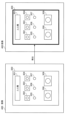
- FIG. 1 shows a board 300.
- the panel 300 is a control panel, a switchboard, a distribution panel, or the like.
- Panel 300 includes a nameplate 301, switches 302-304, lamps 305-307, and meters 308, 309.
- the nameplate 301 has the name of the board 300 written thereon. Switches 302 to 304, lamps 305 to 307, and meters 308 and 309 are to be inspected.
- the inspector photographs the board 300 using the mobile terminal 200. Then, the mobile terminal 200 transmits an image showing the board 300 to the information processing device 100.
- the information processing device 100 automatically associates the board 300 with the inspection target based on the image. This eliminates the need for the inspector to manually associate the inspection target with the panel that includes the inspection target. Therefore, the information processing device 100 can reduce the burden on the inspector.
- the information processing device 100 will be described in detail below.
- FIG. 2 is a diagram showing hardware included in the information processing apparatus according to the first embodiment.
- the information processing device 100 includes a processor 101, a volatile storage device 102, and a nonvolatile storage device 103.
- the processor 101 controls the entire information processing device 100.
- the processor 101 is a CPU (Central Processing Unit), an FPGA (Field Programmable Gate Array), or the like.
- Processor 101 may be a multiprocessor.
- the information processing device 100 may include a processing circuit.
- the volatile storage device 102 is the main storage device of the information processing device 100.
- the volatile storage device 102 is a RAM (Random Access Memory).
- the nonvolatile storage device 103 is an auxiliary storage device of the information processing device 100.
- the nonvolatile storage device 103 is a HDD (Hard Disk Drive) or an SSD (Solid State Drive).
- FIG. 3 is a block diagram showing the functions of the information processing apparatus according to the first embodiment.
- the information processing device 100 includes a storage section 110, an acquisition section 120, a detection section 130, an association section 140, a state detection section 150, and an output section 160.
- the state detection section 150 may also be called an inspection section.
- the storage unit 110 may be realized as a storage area secured in the volatile storage device 102 or the nonvolatile storage device 103.
- Part or all of the acquisition section 120, the detection section 130, the association section 140, the state detection section 150, and the output section 160 may be realized by a processing circuit. Further, part or all of the acquisition unit 120, the detection unit 130, the association unit 140, the state detection unit 150, and the output unit 160 may be implemented as modules of a program executed by the processor 101.
- the program executed by processor 101 is also referred to as a support program.
- the support program is recorded on a recording medium.
- the storage unit 110 may store a position table. Here, a position table is shown.
- FIG. 4 is a diagram showing an example of a position table according to the first embodiment.
- the position table 111 is stored in the storage unit 110.
- the position table 111 is also referred to as position information.
- the position table 111 is information indicating the correspondence between the name of the board, the position of the inspection target, and the name of the inspection target.
- the position table 111 will be explained in detail.
- the position table 111 has items of "disc name", "No.”, "type”, "position”, and "name”. For example, the name of the record is registered in the "disc name” item.
- the location of the inspection target is registered in the “position” item.
- the name of the inspection target is registered in the "Name” field.
- “No. 1” of the board name “ ⁇ machine” indicates the position of the switch 302.
- the position of switch 302 is expressed in distance (ie, X, Y) from the origin.
- the width of the switch 302 is represented by W and H.
- the origin is a corner of the board 300.
- the origin may be the position of the nameplate 301.
- the position of the inspection target may be expressed by the coordinates of the center point of the inspection target. That is, the expression of the position of the inspection target may be an expression other than the position of the position table 111 in FIG. 4.
- the position to be inspected may be expressed as a percentage of the width of the board.
- the position of the inspection target may be expressed by the coordinates of the four corners of the inspection target.
- the position to be inspected may be represented by a circle with coordinates of a center point and a radius.
- the inspection target position may be represented by an inspection target area.
- the unit of position may be a physical length such as cm or m.
- the acquisition unit 120 acquires an image generated by the mobile terminal 200.
- the acquisition unit 120 acquires the position table 111.
- the acquisition unit 120 acquires the position table 111 from the storage unit 110.
- the acquisition unit 120 acquires the position table 111 from an external device. Note that illustrations of external devices are omitted.
- the detection unit 130 detects the board 300 based on the image. For example, the detection unit 130 detects the board 300 using the image and the learned model. Further, for example, the detection unit 130 detects the board 300 using the image and information indicating the shape of the board 300. Note that the learned model and information indicating the shape of the board 300 may be stored in the storage unit 110 or an external device. Detection of the board 300 is illustrated.
- FIG. 5 is a diagram showing an example of board detection according to the first embodiment.
- Image 400 is an image generated by mobile terminal 200.
- the detection unit 130 detects the board 300.
- the detection unit 130 detects the shape of the board 300. That is, the detection unit 130 detects a rectangle. Further, the detection unit 130 may detect four points indicating the four corners of the board 300.
- the detection unit 130 detects the name of the board 300 from within the image area showing the board 300. Specifically, the detection unit 130 performs character recognition on the image area of the board 300. When the detection unit 130 performs character recognition, the detection unit 130 may use OCR (Optical Character Recognition). As a result, the detection unit 130 detects the name “ ⁇ machine” of the board 300 indicated by the nameplate 301.
- OCR Optical Character Recognition
- the detection unit 130 detects the position of the inspection target based on the image area showing the board 300. Specifically, the detection unit 130 can detect the position of the inspection target by detecting the inspection target using object recognition technology. Thereby, the detection unit 130 detects the position of the switch 302 and the like. Furthermore, the position that is the detection result may be expressed by the corner and width of the inspection target, as shown in FIG.
- the association unit 140 associates the board 300 with the inspection target based on the name of the board 300, the position of the inspection target, and the position table 111. Specifically, the association unit 140 specifies the name “ ⁇ machine” of the board 300 from among the “board names” in the position table 111. The association unit 140 identifies the name of the inspection target based on the “position” record of “ ⁇ machine” in the position table 111 and the position of the inspection target. The association unit 140 associates the name “ ⁇ machine” of the board 300 with the name of the inspection target. An image of the association is shown.
- FIG. 6 is a diagram showing an example of an association image according to the first embodiment. As shown in FIG. 6, the panel 300 and the inspection target are associated with each other.
- the state detection unit 150 detects the state of the inspection target in the image. Specifically, the state detection unit 150 detects the state of the inspection target using image analysis technology or a learned model. Specifically, the state detection unit 150 detects whether the switch is in an ON state or an OFF state. The state detection unit 150 also detects whether the lamp is blinking. Furthermore, the state detection unit 150 detects the value indicated by the meter.
- the output unit 160 outputs the inspection result, which is the detection result, to the mobile terminal 200. Thereby, the inspector can check the condition of the inspection target via the mobile terminal 200.
- the inspection result is information in which the name of the panel 300 " ⁇ machine", the name of the inspection target " ⁇ switch", and the state of the inspection target "ON" are associated.
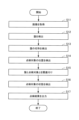
- FIG. 7 is a flowchart illustrating an example of processing executed by the information processing apparatus according to the first embodiment.
- the acquisition unit 120 acquires an image generated by the mobile terminal 200.
- the detection unit 130 detects the board 300 based on the image.
- the detection unit 130 detects the name of the board 300 based on the image.
- the detection unit 130 detects the position of the inspection target based on the image.
- the association unit 140 associates the board 300 with the inspection target based on the name of the board 300, the position of the inspection target, and the position table 111.
- the state detection unit 150 detects the state of the inspection target in the image.
- the output unit 160 outputs the inspection results to the mobile terminal 200.
- the information processing device 100 associates the board 300 with the inspection target. Therefore, there is no need for the inspector to manually associate the inspection target with the panel that includes the inspection target. Therefore, the information processing device 100 can reduce the burden on the inspector.
- FIG. 8 is a diagram showing a support system according to the second embodiment.
- the support system may include an information processing device 100, a mobile terminal 200, and a drawing reading device 500.
- the drawing reading device 500 reads the design drawing (i.e., paper medium) on the board 300.
- the drawing reading device 500 may transmit a diagram showing the board 300 obtained by reading the design drawing to the information processing device 100. Further, the drawing reading device 500 may be included in the mobile terminal 200.
- FIG. 9 is a block diagram showing the functions of the information processing device according to the second embodiment. Components in FIG. 9 that are the same as those shown in FIG. 3 are given the same reference numerals as those shown in FIG.
- the information processing device 100 further includes a generation unit 170. A part or all of the generation unit 170 may be realized by a processing circuit. Further, part or all of the generation unit 170 may be realized as a module of a program executed by the processor 101.
- the acquisition unit 120 may acquire a diagram showing the board 300 from the drawing reading device 500.
- the information processing device 100 may have a drawing reading function.
- the acquisition unit 120 acquires the drawing showing the board 300 read by the information processing device 100.
- the acquisition unit 120 may acquire a CAD (Computer-Aided Design) drawing that is a blueprint of the board 300.
- the CAD drawing is a diagram showing the board 300.
- the acquisition unit 120 acquires a CAD drawing from the storage unit 110.
- the generation unit 170 generates the position table 111 based on the diagram showing the board 300.
- the output unit 160 outputs the position table 111 to the storage unit 110 or an external device.
- the position table 111 is automatically generated. Therefore, for example, the inspector does not need to create the position table 111. Therefore, the information processing device 100 can reduce the burden on the inspector.
- Embodiment 3 Next, Embodiment 3 will be described. In the third embodiment, matters that are different from the first embodiment will be mainly explained. In the third embodiment, explanations of matters common to the first embodiment will be omitted.
- the inspection results are output. After the inspection results are output to the mobile terminal 200, the inspection results disappear in the information processing device 100. Therefore, the fact that the inspection was performed is lost. Therefore, in the third embodiment, a case will be described in which the inspection results are stored in the information processing device 100.
- FIG. 10 is a block diagram showing the functions of the information processing device according to the third embodiment. Components in FIG. 10 that are the same as those shown in FIG. 3 are designated by the same reference numerals as those shown in FIG.
- the information processing device 100 further includes a storage control section 180. A part or all of the storage control unit 180 may be realized by a processing circuit. Furthermore, part or all of the storage control unit 180 may be realized as a module of a program executed by the processor 101.
- the storage control unit 180 stores the inspection results including the inspection date and time in the storage unit 110.
- the information processing device 100 stores the inspection results. Thereby, the information processing device 100 can leave behind the fact that the inspection was performed.
- Embodiment 4 Next, Embodiment 4 will be described. In the fourth embodiment, matters that are different from the third embodiment will be mainly explained. In the fourth embodiment, explanations of matters common to the third embodiment will be omitted.
- the inspection result is a mechanical inspection result.
- Inspectors must also inspect with their own eyes. In other words, the inspector needs to check with his own eyes whether the inspection results are correct. Therefore, in the fourth embodiment, a case where a double check is performed will be described.
- mobile terminal 200 is an HMD.
- the information processing device 100 transmits the inspection results to the HMD. Thereby, the HMD displays the inspection results. A case where the HMD displays inspection results is shown.
- FIG. 11 is a diagram showing an example of the case where the inspection results of the fourth embodiment are displayed. As shown in FIG. 11, the inspection results are displayed on the display (for example, also referred to as a display section) of the HMD. For example, the fact that the switch 302 is in the ON state is displayed on the display.
- the display for example, also referred to as a display section
- the HMD is attached to the inspector.
- the inspector is also referred to as a user.
- the inspector can recognize the inspection results by visually checking the display.
- the HMD has an imaging section.
- the imaging unit may be considered a camera.
- the HMD includes a detection section.
- the detection unit detects that the inspector has viewed the inspection results via the imaging unit.
- the detection unit detects, via the imaging unit, that the inspector's line of sight is a location where the inspection results are displayed. For example, the detection unit may determine that the inspector has seen the inspection result if the inspector has looked at the inspection result for 0.5 seconds.
- the HMD includes an acquisition unit.
- the acquisition unit acquires positional relationship information indicating the positional relationship between the imaging unit and the display.
- the positional relationship information is stored in the storage unit of the HMD.
- the acquisition unit also acquires line-of-sight information indicating the inspector's line of sight.
- the line of sight information is calculated based on information obtained from the imaging unit.
- the detection unit detects the inspection target seen by the inspector based on the positional relationship information, the line-of-sight information, and the image obtained by the imaging unit capturing the direction of the line-of-sight. For example, the detection unit detects that the inspector looks at the switch 302.
- the HMD transmits information indicating that the inspector has viewed the inspection results and information indicating the inspection target viewed by the inspector to the information processing device 100.
- the acquisition unit 120 acquires information indicating that the inspector has viewed the inspection results and information indicating the inspection target viewed by the inspector.
- the storage control unit 180 stores the inspection results viewed by the inspector (i.e., the information displayed on the display) based on the information indicating that the inspector has viewed the inspection results and the information indicating the inspection target viewed by the inspector. If the object of the inspection result) matches the inspection object seen by the inspector (that is, the inspection object detected by the detection section), information indicating that a double check has been performed is stored in the storage section 110. For example, if the target "switch 302" in the inspection result displayed on the display matches the "switch 302" to be inspected seen by the inspector, the storage control unit 180 provides information indicating that a double check has been performed. The information is stored in the storage unit 110.
- the information processing device 100 can store the fact that a double check has been performed.
- Embodiment 5 Next, Embodiment 5 will be described. In Embodiment 5, matters that are different from Embodiments 1 to 4 will be mainly explained. In the fifth embodiment, explanations of matters common to the first to fourth embodiments will be omitted.
- FIG. 12 is a block diagram showing the functions of the mobile terminal according to the fifth embodiment.
- mobile terminal 600 is a smartphone, a tablet terminal, or an HMD.
- Mobile terminal 600 is also referred to as an information processing device.
- the mobile terminal 600 includes a storage section 610, an acquisition section 620, a detection section 630, an association section 640, a state detection section 650, an output section 660, a generation section 670, a storage control section 680, an imaging section 690, and a display section 691.
- the storage unit 610 may be realized as a storage area secured in a volatile storage device or a nonvolatile storage device included in the mobile terminal 600.
- a part or all of the acquisition section 620, the detection section 630, the association section 640, the state detection section 650, the output section 660, the generation section 670, and the storage control section 680 may be realized by a processing circuit included in the mobile terminal 600.
- part or all of the acquisition unit 620, the detection unit 630, the association unit 640, the state detection unit 650, the output unit 660, the generation unit 670, and the storage control unit 680 are modules of a program executed by a processor included in the mobile terminal 600.
- the imaging unit 690 is realized by a camera of the mobile terminal 600.
- the display unit 691 is realized by a display of the mobile terminal 600.
- the imaging unit 690 images the board 300.
- the functions of the acquisition section 620, the detection section 630, the association section 640, the state detection section 650, the generation section 670, and the storage control section 680 are the acquisition section 120, the detection section 130, the association section 140, the state detection section 150, and the generation section 170. , and the functions of the storage control unit 180.
- the acquisition unit 620 acquires an image obtained by capturing an image of the board 300.
- the functions of the acquisition section 620, the detection section 630, the association section 640, the state detection section 650, the generation section 670, and the storage control section 680 are the same as those of the acquisition section 120, the detection section 130, the association section 140, and the state detection section 150.
- the output unit 660 outputs the inspection results to the display unit 691. Thereby, the display section 691 displays the inspection results.
- the mobile terminal 600 can realize the contents of the fourth embodiment.
- the display section 691 is displaying an inspection result that is a detection result.
- the detection unit 630 detects, via the imaging unit 690, that the inspector has viewed the inspection results.
- the acquisition unit 620 acquires positional relationship information indicating the positional relationship between the imaging unit 690 and the display unit 691.
- the acquisition unit 620 also acquires line-of-sight information indicating the inspector's line of sight.
- the detection unit 630 detects the inspection target seen by the inspector based on the positional relationship information, the line of sight information, and the image obtained by the imaging unit 690 capturing the direction of the line of sight.
- the acquisition unit 620 acquires information indicating that the inspector has viewed the inspection results and information indicating the inspection target viewed by the inspector.
- the storage control unit 680 displays the inspection results seen by the inspector (i.e., displayed on the display unit 691) based on information indicating that the inspector has seen the inspection results and information indicating the inspection target seen by the inspector. If the target (inspection result) matches the inspection target seen by the inspector (that is, the inspection target detected by the detection unit 630), information indicating that a double check has been performed is stored in the storage unit 610. do. In this way, mobile terminal 600 can realize the contents of Embodiment 4.
- the mobile terminal 600 has the same effects as the first to fourth embodiments.
- 100 information processing device 101 processor, 102 volatile storage device, 103 nonvolatile storage device, 110 storage section, 111 position table, 120 acquisition section, 130 detection section, 140 association section, 150 Status detection section, 160 Output section, 170 Generation unit, 180 Storage control unit, 200 Mobile terminal, 300 Board, 301 Nameplate, 302-304 Switch, 305-307 Lamp, 308, 309 Meter, 400 Image, 500 Drawing reading device , 600 Mobile terminal, 610 Storage unit, 620 Acquisition unit, 630 detection unit, 640 association unit, 650 state detection unit, 660 output unit, 670 generation unit, 680 storage control unit, 690 imaging unit, 691 display unit.
Landscapes
- Engineering & Computer Science (AREA)
- Manufacturing & Machinery (AREA)
- Power Engineering (AREA)
- Physics & Mathematics (AREA)
- General Physics & Mathematics (AREA)
- Automation & Control Theory (AREA)
- Management, Administration, Business Operations System, And Electronic Commerce (AREA)
- Investigating Materials By The Use Of Optical Means Adapted For Particular Applications (AREA)
Abstract
情報処理装置(100)は、盤の名称と点検対象(301~309)とを含む盤(300)を示す画像、及び盤の名称と点検対象の位置と点検対象の名称との対応関係を示す情報である位置テーブル(111)を取得する取得部(120)と、画像に基づいて、盤(300)を検出し、盤(300)を示す画像領域内から盤の名称を検出し、盤(300)を示す画像領域に基づいて、点検対象(301~309)の位置を検出する検出部(130)と、盤(300)の名称、点検対象(301~309)の位置、及び位置テーブル(111)に基づいて、盤(300)と点検対象(301~309)とを関連付ける関連付け部(140)と、を有する。
Description
本開示は、情報処理装置、支援システム、支援方法、及び支援プログラムに関する。
発電所などの施設には、制御盤、配電盤、分電盤などが設置されている。これらの盤は、日常的又は定期的に点検されている。これらの盤には、メータなどが含まれている。メータなどは、点検対象である。ここで、メータの表示内容を抽出する技術が提案されている(特許文献1を参照)。
上記の技術では、点検対象の内容が抽出される。しかし、当該技術は、どの盤に含まれている点検対象の内容が抽出さているのか分からない。そのため、点検員が、点検対象と、当該点検対象を含む盤との関連付けを手作業で行う必要がある。例えば、点検員は、コンピュータを用いて、関連付けの作業を行う。点検員が作業を行うことは、点検員の負担を大きくする。
本開示の目的は、負担を軽減することである。
本開示の一態様に係る情報処理装置が提供される。情報処理装置は、盤の名称と点検対象とを含む前記盤を示す画像、及び盤の名称と点検対象の位置と点検対象の名称との対応関係を示す情報である位置情報を取得する取得部と、前記画像に基づいて、前記盤を検出し、前記盤を示す画像領域内から前記盤の名称を検出し、前記盤を示す画像領域に基づいて、前記点検対象の位置を検出する検出部と、前記盤の名称、前記点検対象の位置、及び前記位置情報に基づいて、前記盤と前記点検対象とを関連付ける関連付け部と、を有する。
本開示によれば、負担を軽減することができる。
以下、図面を参照しながら実施の形態を説明する。以下の実施の形態は、例にすぎず、本開示の範囲内で種々の変更が可能である。
実施の形態1.
図1は、実施の形態1の支援システムを示す図である。支援システムは、情報処理装置100とモバイル端末200とを含む。情報処理装置100とモバイル端末200とは、ネットワークを介して、接続する。
情報処理装置100は、支援方法を実行する装置である。モバイル端末200は、点検員が使う装置である。例えば、モバイル端末200は、スマートフォン、タブレット端末、又はHMD(Head Mounted Display)である。モバイル端末200は、撮像部を有する。
図1は、実施の形態1の支援システムを示す図である。支援システムは、情報処理装置100とモバイル端末200とを含む。情報処理装置100とモバイル端末200とは、ネットワークを介して、接続する。
情報処理装置100は、支援方法を実行する装置である。モバイル端末200は、点検員が使う装置である。例えば、モバイル端末200は、スマートフォン、タブレット端末、又はHMD(Head Mounted Display)である。モバイル端末200は、撮像部を有する。
図1は、盤300を示している。例えば、盤300は、制御盤、配電盤、分電盤などである。盤300は、銘板301、スイッチ302~304、ランプ305~307、及びメータ308,309を含む。
銘板301には、盤300の名称が記載されている。スイッチ302~304、ランプ305~307、及びメータ308,309は、点検対象である。
銘板301には、盤300の名称が記載されている。スイッチ302~304、ランプ305~307、及びメータ308,309は、点検対象である。
点検員は、モバイル端末200を用いて、盤300を撮影する。そして、モバイル端末200は、盤300を示す画像を情報処理装置100に送信する。情報処理装置100は、画像に基づいて、盤300と点検対象とを自動的に関連付ける。これにより、点検員が、点検対象と、当該点検対象を含む盤との関連付けを手作業で行う必要がない。よって、情報処理装置100は、点検員の負担を軽減することができる。
以下、情報処理装置100を詳細に説明する。
以下、情報処理装置100を詳細に説明する。
次に、情報処理装置100が有するハードウェアを説明する。
図2は、実施の形態1の情報処理装置が有するハードウェアを示す図である。情報処理装置100は、プロセッサ101、揮発性記憶装置102、及び不揮発性記憶装置103を有する。
図2は、実施の形態1の情報処理装置が有するハードウェアを示す図である。情報処理装置100は、プロセッサ101、揮発性記憶装置102、及び不揮発性記憶装置103を有する。
プロセッサ101は、情報処理装置100全体を制御する。例えば、プロセッサ101は、CPU(Central Processing Unit)、FPGA(Field Programmable Gate Array)などである。プロセッサ101は、マルチプロセッサでもよい。また、情報処理装置100は、処理回路を有してもよい。
揮発性記憶装置102は、情報処理装置100の主記憶装置である。例えば、揮発性記憶装置102は、RAM(Random Access Memory)である。不揮発性記憶装置103は、情報処理装置100の補助記憶装置である。例えば、不揮発性記憶装置103は、HDD(Hard Disk Drive)、又はSSD(Solid State Drive)である。
次に、情報処理装置100が有する機能を説明する。
図3は、実施の形態1の情報処理装置の機能を示すブロック図である。情報処理装置100は、記憶部110、取得部120、検出部130、関連付け部140、状態検出部150、及び出力部160を有する。なお、状態検出部150は、点検部と呼んでもよい。
図3は、実施の形態1の情報処理装置の機能を示すブロック図である。情報処理装置100は、記憶部110、取得部120、検出部130、関連付け部140、状態検出部150、及び出力部160を有する。なお、状態検出部150は、点検部と呼んでもよい。
記憶部110は、揮発性記憶装置102又は不揮発性記憶装置103に確保した記憶領域として実現してもよい。
取得部120、検出部130、関連付け部140、状態検出部150、及び出力部160の一部又は全部は、処理回路によって実現してもよい。また、取得部120、検出部130、関連付け部140、状態検出部150、及び出力部160の一部又は全部は、プロセッサ101が実行するプログラムのモジュールとして実現してもよい。例えば、プロセッサ101が実行するプログラムは、支援プログラムとも言う。例えば、支援プログラムは、記録媒体に記録されている。
取得部120、検出部130、関連付け部140、状態検出部150、及び出力部160の一部又は全部は、処理回路によって実現してもよい。また、取得部120、検出部130、関連付け部140、状態検出部150、及び出力部160の一部又は全部は、プロセッサ101が実行するプログラムのモジュールとして実現してもよい。例えば、プロセッサ101が実行するプログラムは、支援プログラムとも言う。例えば、支援プログラムは、記録媒体に記録されている。
記憶部110は、位置テーブルを記憶してもよい。ここで、位置テーブルを示す。
図4は、実施の形態1の位置テーブルの例を示す図である。例えば、位置テーブル111は、記憶部110に格納されている。位置テーブル111は、位置情報とも言う。位置テーブル111は、盤の名称と点検対象の位置と点検対象の名称との対応関係を示す情報である。詳細に、位置テーブル111を説明する。位置テーブル111は、“盤名称”、“No.”、“種類”、“位置”、及び“名称”の項目を有する。例えば、“盤名称”の項目には、盤の名称が登録される。“位置”の項目には、点検対象の位置が登録される。“名称”の項目には、点検対象の名称が登録される。
盤名称“△△機”の“No.1”は、スイッチ302の位置を示している。例えば、スイッチ302の位置は、原点からの距離(すなわち、X、Y)で表される。また、スイッチ302の幅は、WとHで表される。なお、原点は、盤300の角である。
原点は、銘板301の位置でもよい。点検対象の位置は、点検対象の中心点の座標で表されてもよい。すなわち、点検対象の位置の表現は、図4の位置テーブル111の位置以外の表現でもよい。例えば、点検対象の位置は、盤の幅に対する割合で表されてもよい。また、例えば、点検対象の位置は、点検対象の四隅の座標で表されてもよい。例えば、点検対象の位置は、中心点の座標と半径による円で表されてもよい。点検対象の位置は、点検対象の領域で表されてもよい。また、位置の単位は、cm又はmなどの物理的な長さでもよい。
原点は、銘板301の位置でもよい。点検対象の位置は、点検対象の中心点の座標で表されてもよい。すなわち、点検対象の位置の表現は、図4の位置テーブル111の位置以外の表現でもよい。例えば、点検対象の位置は、盤の幅に対する割合で表されてもよい。また、例えば、点検対象の位置は、点検対象の四隅の座標で表されてもよい。例えば、点検対象の位置は、中心点の座標と半径による円で表されてもよい。点検対象の位置は、点検対象の領域で表されてもよい。また、位置の単位は、cm又はmなどの物理的な長さでもよい。
取得部120は、モバイル端末200が生成した画像を取得する。
取得部120は、位置テーブル111を取得する。例えば、取得部120は、位置テーブル111を記憶部110から取得する。また、例えば、取得部120は、位置テーブル111を外部装置から取得する。なお、外部装置の図は、省略されている。
取得部120は、位置テーブル111を取得する。例えば、取得部120は、位置テーブル111を記憶部110から取得する。また、例えば、取得部120は、位置テーブル111を外部装置から取得する。なお、外部装置の図は、省略されている。
検出部130は、画像に基づいて、盤300を検出する。例えば、検出部130は、画像と学習済モデルとを用いて、盤300を検出する。また、例えば、検出部130は、画像と、盤300の形状を示す情報とを用いて、盤300を検出する。なお、学習済モデルと盤300の形状を示す情報とは、記憶部110又は外部装置に格納されてもよい。盤300の検出を例示する。
図5は、実施の形態1の盤の検出の例を示す図である。画像400は、モバイル端末200が生成した画像である。図5が示すように、検出部130は、盤300を検出する。正確には、検出部130は、盤300の形状を検出する。すなわち、検出部130は、長方形を検出する。また、検出部130は、盤300の四隅を示す4点を検出してもよい。
検出部130は、盤300を示す画像領域内から、盤300の名称を検出する。詳細には、検出部130は、盤300の画像領域に対して文字認識を行う。検出部130が文字認識を行う場合、検出部130は、OCR(Optical Character Recognition)を用いてもよい。これにより、検出部130は、銘板301が示す盤300の名称“△△機”を検出する。
検出部130は、盤300を示す画像領域に基づいて、点検対象の位置を検出する。詳細には、検出部130は、物体認識技術を用いて点検対象を検出することで、点検対象の位置を検出できる。これにより、検出部130は、スイッチ302などの位置を検出する。また、検出結果である位置は、図4で示したように、点検対象の角と幅で表されてもよい。
関連付け部140は、盤300の名称、点検対象の位置、及び位置テーブル111に基づいて、盤300と点検対象とを関連付ける。詳細には、関連付け部140は、位置テーブル111の“盤名称”の中から、盤300の名称“△△機”を特定する。関連付け部140は、位置テーブル111の“△△機”の“位置”のレコードと、点検対象の位置とに基づいて、点検対象の名称を特定する。関連付け部140は、盤300の名称“△△機”と、点検対象の名称とを関連付ける。関連付けのイメージを示す。
図6は、実施の形態1の関連付けのイメージの例を示す図である。図6が示すように、盤300と点検対象とが、関連付けられる。
状態検出部150は、画像内の点検対象の状態を検出する。詳細には、状態検出部150は、画像解析技術又は学習済モデルを用いて、点検対象の状態を検出する。具体的には、状態検出部150は、スイッチがONの状態であるかOFFの状態であるかを検出する。また、状態検出部150は、ランプが点滅しているか否かを検出する。さらに、状態検出部150は、メータが示す値を検出する。
出力部160は、検出結果である点検結果をモバイル端末200に出力する。これにより、点検員は、モバイル端末200を介して、点検対象の状態を確認できる。なお、例えば、点検結果は、盤300の名称“△△機”と、点検対象の名称“○○スイッチ”と、点検対象の状態“ON”とが関連付けされた情報である。
次に、情報処理装置100が実行する処理を、フローチャートを用いて、説明する。
図7は、実施の形態1の情報処理装置が実行する処理の例を示すフローチャートである。
(ステップS11)取得部120は、モバイル端末200が生成した画像を取得する。
(ステップS12)検出部130は、画像に基づいて、盤300を検出する。
(ステップS13)検出部130は、画像に基づいて、盤300の名称を検出する。
(ステップS14)検出部130は、画像に基づいて、点検対象の位置を検出する。
(ステップS15)関連付け部140は、盤300の名称、点検対象の位置、及び位置テーブル111に基づいて、盤300と点検対象とを関連付ける。
(ステップS16)状態検出部150は、画像内の点検対象の状態を検出する。
(ステップS17)出力部160は、モバイル端末200に点検結果を出力する。
実施の形態1によれば、情報処理装置100は、盤300と点検対象とを関連付ける。そのため、点検員が、点検対象と、当該点検対象を含む盤との関連付けを手作業で行う必要がない。よって、情報処理装置100は、点検員の負担を軽減することができる。
実施の形態2.
次に、実施の形態2を説明する。実施の形態2では、実施の形態1と相違する事項を主に説明する。そして、実施の形態2では、実施の形態1と共通する事項の説明を省略する。
図8は、実施の形態2の支援システムを示す図である。支援システムは、情報処理装置100とモバイル端末200と図面読取装置500とを含んでもよい。
次に、実施の形態2を説明する。実施の形態2では、実施の形態1と相違する事項を主に説明する。そして、実施の形態2では、実施の形態1と共通する事項の説明を省略する。
図8は、実施の形態2の支援システムを示す図である。支援システムは、情報処理装置100とモバイル端末200と図面読取装置500とを含んでもよい。
図面読取装置500は、盤300の設計図(すなわち、紙媒体)を読み取る。図面読取装置500は、当該設計図を読み取ることで得られた、盤300を示す図を情報処理装置100に送信してもよい。また、図面読取装置500は、モバイル端末200に含まれてもよい。
図9は、実施の形態2の情報処理装置の機能を示すブロック図である。図3に示される構成と同じ図9の構成は、図3に示される符号と同じ符号を付している。情報処理装置100は、さらに生成部170を有する。生成部170の一部又は全部は、処理回路によって実現してもよい。また、生成部170の一部又は全部は、プロセッサ101が実行するプログラムのモジュールとして実現してもよい。
取得部120は、盤300を示す図を図面読取装置500から取得してもよい。ここで、情報処理装置100は、図面読取機能を有してもよい。情報処理装置100が図面読取機能を有する場合、取得部120は、情報処理装置100によって読取られた、盤300を示す図を取得する。
また、取得部120は、盤300の設計図であるCAD(Computer-Aided Design)図面を取得してもよい。CAD図面は、盤300を示す図である。例えば、取得部120は、CAD図面を記憶部110から取得する。
生成部170は、盤300を示す図に基づいて、位置テーブル111を生成する。出力部160は、記憶部110又は外部装置に位置テーブル111を出力する。
実施の形態2によれば、位置テーブル111が自動的に生成される。そのため、例えば、点検員は、位置テーブル111を作成しなくて済む。よって、情報処理装置100は、点検員の負担を軽減できる。
実施の形態3.
次に、実施の形態3を説明する。実施の形態3では、実施の形態1と相違する事項を主に説明する。そして、実施の形態3では、実施の形態1と共通する事項の説明を省略する。
次に、実施の形態3を説明する。実施の形態3では、実施の形態1と相違する事項を主に説明する。そして、実施の形態3では、実施の形態1と共通する事項の説明を省略する。
実施の形態1では、点検結果が出力される場合を説明した。点検結果がモバイル端末200に出力された後、点検結果は、情報処理装置100の中で消失する。そのため、点検が行われた事実が、失われる。そこで、実施の形態3では、点検結果が、情報処理装置100に格納される場合を説明する。
図10は、実施の形態3の情報処理装置の機能を示すブロック図である。図3に示される構成と同じ図10の構成は、図3に示される符号と同じ符号を付している。情報処理装置100は、さらに格納制御部180を有する。格納制御部180の一部又は全部は、処理回路によって実現してもよい。また、格納制御部180の一部又は全部は、プロセッサ101が実行するプログラムのモジュールとして実現してもよい。
格納制御部180は、点検日時を含む点検結果を記憶部110に格納する。
実施の形態3によれば、情報処理装置100は、点検結果を記憶する。これにより、情報処理装置100は、点検が行われた事実を残すことができる。
実施の形態4.
次に、実施の形態4を説明する。実施の形態4では、実施の形態3と相違する事項を主に説明する。そして、実施の形態4では、実施の形態3と共通する事項の説明を省略する。
次に、実施の形態4を説明する。実施の形態4では、実施の形態3と相違する事項を主に説明する。そして、実施の形態4では、実施の形態3と共通する事項の説明を省略する。
実施の形態3では、点検結果が情報処理装置100に格納される場合を説明した。ここで、当該点検結果は、機械による点検結果である。点検員は、自分の目でも点検する必要がある。すなわち、点検員は、点検結果が正しいかを自分の目でも点検する必要がある。そこで、実施の形態4では、ダブルチェックが行われる場合を説明する。
実施の形態4では、モバイル端末200は、HMDである。情報処理装置100は、点検結果をHMDに送信する。これにより、HMDは、点検結果を表示する。HMDが点検結果を表示する場合を示す。
図11は、実施の形態4の点検結果が表示される場合の例を示す図である。図11が示すように、点検結果が、HMDのディスプレイ(例えば、表示部とも言う。)に表示される。例えば、スイッチ302がONの状態であることが、当該ディスプレイに表示される。
HMDは、点検員に装着されている。なお、点検員は、ユーザとも言う。点検員は、当該ディスプレイを視認することで、点検結果を認識できる。ここで、HMDは、撮像部を有する。当該撮像部は、カメラと考えてもよい。また、HMDは、検出部を有する。当該検出部は、当該撮像部を介して、点検員が点検結果を見たことを検出する。詳細には、当該検出部は、当該撮像部を介して、点検員の視線の先が、点検結果が表示されている箇所であることを検出する。また、例えば、当該検出部は、0.5秒間、点検員が点検結果を見た場合、点検員が点検結果を見たと判定してもよい。
また、HMDは、取得部を有する。当該取得部は、当該撮像部と当該ディスプレイとの位置関係を示す位置関係情報を取得する。なお、例えば、当該位置関係情報は、HMDの記憶部に格納されている。また、当該取得部は、点検員の視線を示す視線情報を取得する。なお、例えば、当該視線情報は、当該撮像部から得られた情報に基づいて算出される。当該検出部は、当該位置関係情報と、当該視線情報と、当該撮像部が視線の方向を撮像することにより得られた画像とに基づいて、点検員が見た点検対象を検出する。例えば、当該検出部は、点検員がスイッチ302を見たことを検出する。
HMDは、点検員が点検結果を見たことを示す情報と、点検員が見た点検対象を示す情報とを情報処理装置100に送信する。
取得部120は、点検員が点検結果を見たことを示す情報と、点検員が見た点検対象を示す情報とを取得する。
格納制御部180は、点検員が点検結果を見たことを示す情報と、点検員が見た点検対象を示す情報とに基づいて、点検員が見た点検結果(すなわち、ディスプレイに表示された点検結果)の対象が、点検員が見た点検対象(すなわち、当該検出部により検出された点検対象)と一致する場合、ダブルチェックが行われたことを示す情報を記憶部110に格納する。例えば、格納制御部180は、ディスプレイに表示された点検結果の対象“スイッチ302”が、点検員が見た点検対象“スイッチ302”と一致する場合、ダブルチェックが行われたことを示す情報を記憶部110に格納する。
実施の形態4によれば、情報処理装置100は、ダブルチェックが行われた事実を記憶することができる。
実施の形態5.
次に、実施の形態5を説明する。実施の形態5では、実施の形態1~4と相違する事項を主に説明する。そして、実施の形態5では、実施の形態1~4と共通する事項の説明を省略する。
次に、実施の形態5を説明する。実施の形態5では、実施の形態1~4と相違する事項を主に説明する。そして、実施の形態5では、実施の形態1~4と共通する事項の説明を省略する。
実施の形態1~4では、情報処理装置100が主な処理を実行する場合を説明した。実施の形態5では、モバイル端末が、情報処理装置100と同じ機能を有する場合を説明する。
図12は、実施の形態5のモバイル端末の機能を示すブロック図である。例えば、モバイル端末600は、スマートフォン、タブレット端末、又はHMDである。モバイル端末600は、情報処理装置とも言う。
モバイル端末600は、記憶部610、取得部620、検出部630、関連付け部640、状態検出部650、出力部660、生成部670、格納制御部680、撮像部690、及び表示部691を有する。
記憶部610は、モバイル端末600が有する揮発性記憶装置又は不揮発性記憶装置に確保した記憶領域として実現してもよい。
取得部620、検出部630、関連付け部640、状態検出部650、出力部660、生成部670、格納制御部680の一部又は全部は、モバイル端末600が有する処理回路によって実現してもよい。また、取得部620、検出部630、関連付け部640、状態検出部650、出力部660、生成部670、格納制御部680の一部又は全部は、モバイル端末600が有するプロセッサが実行するプログラムのモジュールとして実現してもよい。
例えば、撮像部690は、モバイル端末600のカメラによって実現される。例えば、表示部691は、モバイル端末600のディスプレイによって実現される。
取得部620、検出部630、関連付け部640、状態検出部650、出力部660、生成部670、格納制御部680の一部又は全部は、モバイル端末600が有する処理回路によって実現してもよい。また、取得部620、検出部630、関連付け部640、状態検出部650、出力部660、生成部670、格納制御部680の一部又は全部は、モバイル端末600が有するプロセッサが実行するプログラムのモジュールとして実現してもよい。
例えば、撮像部690は、モバイル端末600のカメラによって実現される。例えば、表示部691は、モバイル端末600のディスプレイによって実現される。
まず、撮像部690の機能を説明する。撮像部690は、盤300を撮像する。
取得部620、検出部630、関連付け部640、状態検出部650、生成部670、及び格納制御部680の機能は、取得部120、検出部130、関連付け部140、状態検出部150、生成部170、及び格納制御部180の機能と同じである。例えば、取得部620は、盤300を撮像することにより得られた画像を取得する。このように、取得部620、検出部630、関連付け部640、状態検出部650、生成部670、及び格納制御部680の機能は、取得部120、検出部130、関連付け部140、状態検出部150、生成部170、及び格納制御部180の機能と同じである。そのため、取得部620、検出部630、関連付け部640、状態検出部650、生成部670、及び格納制御部680の機能の説明は、省略する。
出力部660は、点検結果を表示部691に出力する。これにより、表示部691は、点検結果を表示する。
モバイル端末600は、実施の形態4の内容を実現できる。まず、表示部691は、検出結果である点検結果を表示しているものとする。検出部630は、撮像部690を介して、点検員が点検結果を見たことを検出する。取得部620は、撮像部690と表示部691との位置関係を示す位置関係情報を取得する。また、取得部620は、点検員の視線を示す視線情報を取得する。検出部630は、当該位置関係情報と、当該視線情報と、撮像部690が視線の方向を撮像することにより得られた画像とに基づいて、点検員が見た点検対象を検出する。取得部620は、点検員が点検結果を見たことを示す情報と、点検員が見た点検対象を示す情報とを取得する。格納制御部680は、点検員が点検結果を見たことを示す情報と、点検員が見た点検対象を示す情報とに基づいて、点検員が見た点検結果(すなわち、表示部691に表示された点検結果)の対象が、点検員が見た点検対象(すなわち、検出部630により検出された点検対象)と一致する場合、ダブルチェックが行われたことを示す情報を記憶部610に格納する。このように、モバイル端末600は、実施の形態4の内容を実現できる。
実施の形態5によれば、モバイル端末600は、実施の形態1~4と同じ効果を奏する。
以上に説明した各実施の形態における特徴は、互いに適宜組み合わせることができる。
100 情報処理装置、 101 プロセッサ、 102 揮発性記憶装置、 103 不揮発性記憶装置、 110 記憶部、 111 位置テーブル、 120 取得部、 130 検出部、 140 関連付け部、 150 状態検出部、 160 出力部、 170 生成部、 180 格納制御部、 200 モバイル端末、 300 盤、 301 銘板、 302~304 スイッチ、 305~307 ランプ、 308,309 メータ、 400 画像、 500 図面読取装置、 600 モバイル端末、 610 記憶部、 620 取得部、 630 検出部、 640 関連付け部、 650 状態検出部、 660 出力部、 670 生成部、 680 格納制御部、 690 撮像部、 691 表示部。
Claims (9)
- 盤の名称と点検対象とを含む前記盤を示す画像、及び盤の名称と点検対象の位置と点検対象の名称との対応関係を示す情報である位置情報を取得する取得部と、
前記画像に基づいて、前記盤を検出し、前記盤を示す画像領域内から前記盤の名称を検出し、前記盤を示す画像領域に基づいて、前記点検対象の位置を検出する検出部と、
前記盤の名称、前記点検対象の位置、及び前記位置情報に基づいて、前記盤と前記点検対象とを関連付ける関連付け部と、
を有する情報処理装置。 - 前記画像内の前記点検対象の状態を検出する状態検出部と、
検出結果である点検結果を出力する出力部と、
をさらに有する、
請求項1に記載の情報処理装置。 - 前記盤を撮像する撮像部と、
前記点検結果を表示する表示部と、
をさらに有する、
請求項2に記載の情報処理装置。 - 記憶部と、
前記点検結果を前記記憶部に格納する格納制御部と、
をさらに有する、
請求項2又は3に記載の情報処理装置。 - 記憶部と、
格納制御部と、
をさらに有し、
前記取得部は、ユーザが前記点検結果を見たことを示す情報と、前記ユーザが見た点検対象を示す情報とを取得し、
前記格納制御部は、前記ユーザが前記点検結果を見たことを示す情報と、前記ユーザが見た点検対象を示す情報とに基づいて、前記ユーザが見た前記点検結果の対象が、前記ユーザが見た点検対象と一致する場合、ダブルチェックが行われたことを示す情報を前記記憶部に格納する、
請求項2から4のいずれか1項に記載の情報処理装置。 - 生成部をさらに有し、
前記取得部は、前記盤を示す図を取得し、
前記生成部は、前記盤を示す図に基づいて、前記位置情報を生成する、
請求項1から5のいずれか1項に記載の情報処理装置。 - 盤の名称と点検対象とを含む前記盤を撮像する撮像部を有するモバイル端末と、
情報処理装置と、
を含み、
前記情報処理装置は、
前記モバイル端末が生成した、前記盤を示す画像を取得し、盤の名称と点検対象の位置と点検対象の名称との対応関係を示す情報である位置情報を取得する取得部と、
前記画像に基づいて、前記盤を検出し、前記盤を示す画像領域内から前記盤の名称を検出し、前記盤を示す画像領域に基づいて、前記点検対象の位置を検出する検出部と、
前記盤の名称、前記点検対象の位置、及び前記位置情報に基づいて、前記盤と前記点検対象とを関連付ける関連付け部と、
を有する、
支援システム。 - 情報処理装置が、
盤の名称と点検対象とを含む前記盤を示す画像、及び盤の名称と点検対象の位置と点検対象の名称との対応関係を示す情報である位置情報を取得し、前記画像に基づいて、前記盤を検出し、前記盤を示す画像領域内から前記盤の名称を検出し、前記盤を示す画像領域に基づいて、前記点検対象の位置を検出し、
前記盤の名称、前記点検対象の位置、及び前記位置情報に基づいて、前記盤と前記点検対象とを関連付ける、
支援方法。 - 情報処理装置に、
盤の名称と点検対象とを含む前記盤を示す画像、及び盤の名称と点検対象の位置と点検対象の名称との対応関係を示す情報である位置情報を取得し、前記画像に基づいて、前記盤を検出し、前記盤を示す画像領域内から前記盤の名称を検出し、前記盤を示す画像領域に基づいて、前記点検対象の位置を検出し、
前記盤の名称、前記点検対象の位置、及び前記位置情報に基づいて、前記盤と前記点検対象とを関連付ける、
処理を実行させる支援プログラム。
Priority Applications (2)
| Application Number | Priority Date | Filing Date | Title |
|---|---|---|---|
| PCT/JP2022/010021 WO2023170791A1 (ja) | 2022-03-08 | 2022-03-08 | 情報処理装置、支援システム、支援方法、及び支援プログラム |
| JP2023573045A JP7433568B2 (ja) | 2022-03-08 | 2022-03-08 | 情報処理装置、支援システム、支援方法、及び支援プログラム |
Applications Claiming Priority (1)
| Application Number | Priority Date | Filing Date | Title |
|---|---|---|---|
| PCT/JP2022/010021 WO2023170791A1 (ja) | 2022-03-08 | 2022-03-08 | 情報処理装置、支援システム、支援方法、及び支援プログラム |
Publications (1)
| Publication Number | Publication Date |
|---|---|
| WO2023170791A1 true WO2023170791A1 (ja) | 2023-09-14 |
Family
ID=87936378
Family Applications (1)
| Application Number | Title | Priority Date | Filing Date |
|---|---|---|---|
| PCT/JP2022/010021 WO2023170791A1 (ja) | 2022-03-08 | 2022-03-08 | 情報処理装置、支援システム、支援方法、及び支援プログラム |
Country Status (2)
| Country | Link |
|---|---|
| JP (1) | JP7433568B2 (ja) |
| WO (1) | WO2023170791A1 (ja) |
Citations (5)
| Publication number | Priority date | Publication date | Assignee | Title |
|---|---|---|---|---|
| US5805813A (en) * | 1996-07-26 | 1998-09-08 | Schweitzer Engineering Laboratories, Inc. | System for visual monitoring of operational indicators in an electric power system |
| JP2011081715A (ja) * | 2009-10-09 | 2011-04-21 | Toshiba Corp | 監視システム及び監視方法 |
| JP2018045655A (ja) * | 2016-09-16 | 2018-03-22 | 株式会社東芝 | 監視装置 |
| JP2019057041A (ja) * | 2017-09-20 | 2019-04-11 | 株式会社東芝 | 監視装置 |
| JP2020077045A (ja) * | 2018-11-05 | 2020-05-21 | Necフィールディング株式会社 | 情報処理装置、判定方法及びプログラム |
-
2022
- 2022-03-08 WO PCT/JP2022/010021 patent/WO2023170791A1/ja active Application Filing
- 2022-03-08 JP JP2023573045A patent/JP7433568B2/ja active Active
Patent Citations (5)
| Publication number | Priority date | Publication date | Assignee | Title |
|---|---|---|---|---|
| US5805813A (en) * | 1996-07-26 | 1998-09-08 | Schweitzer Engineering Laboratories, Inc. | System for visual monitoring of operational indicators in an electric power system |
| JP2011081715A (ja) * | 2009-10-09 | 2011-04-21 | Toshiba Corp | 監視システム及び監視方法 |
| JP2018045655A (ja) * | 2016-09-16 | 2018-03-22 | 株式会社東芝 | 監視装置 |
| JP2019057041A (ja) * | 2017-09-20 | 2019-04-11 | 株式会社東芝 | 監視装置 |
| JP2020077045A (ja) * | 2018-11-05 | 2020-05-21 | Necフィールディング株式会社 | 情報処理装置、判定方法及びプログラム |
Also Published As
| Publication number | Publication date |
|---|---|
| JP7433568B2 (ja) | 2024-02-19 |
| JPWO2023170791A1 (ja) | 2023-09-14 |
Similar Documents
| Publication | Publication Date | Title |
|---|---|---|
| KR101808015B1 (ko) | 최적 문자 인식을 위한 모바일 문서 획득 지원 | |
| US20130010068A1 (en) | Augmented reality system | |
| CN108830180B (zh) | 电子考勤方法、装置及电子设备 | |
| US11380140B2 (en) | Inspection assistance device, inspection assistance method, and recording medium | |
| JP2017162103A (ja) | 点検作業支援システム、点検作業支援方法、点検作業支援プログラム | |
| US7377650B2 (en) | Projection of synthetic information | |
| JP2015061339A (ja) | 結線作業支援システム | |
| AU2007231552A1 (en) | Testing surveillance camera installations | |
| US20160054806A1 (en) | Data processing apparatus, data processing system, control method for data processing apparatus, and storage medium | |
| CN112559341A (zh) | 一种画面测试方法、装置、设备及存储介质 | |
| JPWO2016084151A1 (ja) | 作業支援システム、作業支援装置及び作業支援方法 | |
| JP2009116483A (ja) | 情報機器および、その保守情報支援システム | |
| WO2023170791A1 (ja) | 情報処理装置、支援システム、支援方法、及び支援プログラム | |
| JP2018054435A (ja) | 検査装置 | |
| EP3306453B1 (en) | Apparatus and method for assisting an operator of an alarm screen | |
| US20170272806A1 (en) | Information processing apparatus and non-transitory computer readable medium | |
| JP2007305147A (ja) | 作業支援方法 | |
| US7348999B1 (en) | Alignment method and apparatus | |
| Tang et al. | Development of an augmented reality approach to mammographic training: overcoming some real world challenges | |
| JP2018106389A5 (ja) | ||
| CN103824143A (zh) | 零件组装指示系统及方法 | |
| JP2021004840A (ja) | 検針作業表示部材および検針情報入力装置 | |
| Cappi et al. | DYSCO Vis.: DYnamic Self-Correction for Obstructed Visualizations | |
| WO2018158818A1 (ja) | 点検支援装置、点検支援方法および記録媒体 | |
| US20230070529A1 (en) | Processing apparatus, processing method, and non-transitory storage medium |
Legal Events
| Date | Code | Title | Description |
|---|---|---|---|
| 121 | Ep: the epo has been informed by wipo that ep was designated in this application |
Ref document number: 22930776 Country of ref document: EP Kind code of ref document: A1 |
|
| WWE | Wipo information: entry into national phase |
Ref document number: 2023573045 Country of ref document: JP |