WO2023166809A1 - バッテリモジュール - Google Patents
バッテリモジュール Download PDFInfo
- Publication number
- WO2023166809A1 WO2023166809A1 PCT/JP2022/045515 JP2022045515W WO2023166809A1 WO 2023166809 A1 WO2023166809 A1 WO 2023166809A1 JP 2022045515 W JP2022045515 W JP 2022045515W WO 2023166809 A1 WO2023166809 A1 WO 2023166809A1
- Authority
- WO
- WIPO (PCT)
- Prior art keywords
- battery
- battery module
- battery cells
- cell holder
- cell
- Prior art date
Links
Images


Classifications
-
- H—ELECTRICITY
- H01—ELECTRIC ELEMENTS
- H01M—PROCESSES OR MEANS, e.g. BATTERIES, FOR THE DIRECT CONVERSION OF CHEMICAL ENERGY INTO ELECTRICAL ENERGY
- H01M50/00—Constructional details or processes of manufacture of the non-active parts of electrochemical cells other than fuel cells, e.g. hybrid cells
- H01M50/20—Mountings; Secondary casings or frames; Racks, modules or packs; Suspension devices; Shock absorbers; Transport or carrying devices; Holders
- H01M50/204—Racks, modules or packs for multiple batteries or multiple cells
- H01M50/207—Racks, modules or packs for multiple batteries or multiple cells characterised by their shape
- H01M50/213—Racks, modules or packs for multiple batteries or multiple cells characterised by their shape adapted for cells having curved cross-section, e.g. round or elliptic
-
- H—ELECTRICITY
- H01—ELECTRIC ELEMENTS
- H01M—PROCESSES OR MEANS, e.g. BATTERIES, FOR THE DIRECT CONVERSION OF CHEMICAL ENERGY INTO ELECTRICAL ENERGY
- H01M50/00—Constructional details or processes of manufacture of the non-active parts of electrochemical cells other than fuel cells, e.g. hybrid cells
- H01M50/20—Mountings; Secondary casings or frames; Racks, modules or packs; Suspension devices; Shock absorbers; Transport or carrying devices; Holders
- H01M50/284—Mountings; Secondary casings or frames; Racks, modules or packs; Suspension devices; Shock absorbers; Transport or carrying devices; Holders with incorporated circuit boards, e.g. printed circuit boards [PCB]
-
- Y—GENERAL TAGGING OF NEW TECHNOLOGICAL DEVELOPMENTS; GENERAL TAGGING OF CROSS-SECTIONAL TECHNOLOGIES SPANNING OVER SEVERAL SECTIONS OF THE IPC; TECHNICAL SUBJECTS COVERED BY FORMER USPC CROSS-REFERENCE ART COLLECTIONS [XRACs] AND DIGESTS
- Y02—TECHNOLOGIES OR APPLICATIONS FOR MITIGATION OR ADAPTATION AGAINST CLIMATE CHANGE
- Y02E—REDUCTION OF GREENHOUSE GAS [GHG] EMISSIONS, RELATED TO ENERGY GENERATION, TRANSMISSION OR DISTRIBUTION
- Y02E60/00—Enabling technologies; Technologies with a potential or indirect contribution to GHG emissions mitigation
- Y02E60/10—Energy storage using batteries
Definitions
- the present disclosure relates to a battery module in which a plurality of battery cells are held by cell holders and built into an exterior case, and in particular to a battery module that can ensure safety against water entering the exterior case.
- a battery module that contains multiple battery cells in an exterior case holds each battery cell in place with a cell holder made of insulating material.
- a plurality of battery cells can be connected in series to set the optimum output voltage for the application, and can be connected in parallel to increase the maximum current.
- the above battery modules are required to be safe even in a submerged usage environment.
- a battery module has also been developed in which a drain hole is provided in the exterior case to drain the inflowing water to the outside (see Patent Document 1).
- Battery modules are required to be safe even in a submerged usage environment.
- the harmful effects of intruding water can be realized by a structure in which the entire interior is buried in potting resin.
- this structure has the drawback that the potting resin makes the whole battery module heavy.
- it is possible to prevent water ingress by making the outer case of the battery module waterproof.
- a battery module that has a drain hole in the outer case to drain water that enters the outer case outside the outer case has the drawback that it cannot always ensure sufficient safety in various usage environments. In particular, it is difficult to ensure safety in a usage environment where the inflowing water is discharged after being submerged.
- the present disclosure has been developed for the purpose of overcoming the above drawbacks, and one purpose of the present disclosure is to provide a battery module that can ensure safety even in a submerged environment.
- a battery module has a plurality of battery cells arranged in fixed positions by cell holders and housed in an exterior case.
- the cell holder consists of a holding part into which the lower part of the battery cell is inserted and placed in a fixed position, a drainage space exposing the battery cell above the holding part, and a drainage opening through which water flowing into the drainage space is drained. and an insulating partition wall projecting upward from the surface of the holding part, disposed in the drainage space, and having a lateral width (W) positioned within the facing area of the battery cells having a potential difference.
- W lateral width
- the above battery modules have the advantage of ensuring safety even in submerged environments.
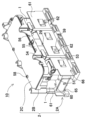
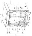
- FIG. 1 is a partially enlarged perspective view of a battery module according to an embodiment of the present disclosure
- FIG. 2 is an exploded perspective view of the battery module shown in FIG. 1.
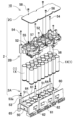
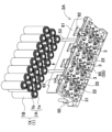
- FIG. 3 is a perspective view of a battery assembly housed in the battery module shown in FIG. 2.
- FIG. 4 is an exploded perspective view of the battery assembly shown in FIG. 3.
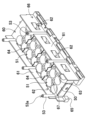
- FIG. 5 is an enlarged perspective view of the body cell holder shown in FIG. 4;
- FIG. 6 is an enlarged bottom perspective view of the body cell holder shown in FIG. 4;
- FIG. 7 is a plan view of the body cell holder shown in FIG. 5.
- FIG. 8 is a cross-sectional view of the body cell holder shown in FIG. 7 taken along line VIII-VIII.
- FIG. 9 is a cross-sectional view of the main body cell holder shown in FIG. 7 taken along the line IX-IX.
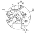
- 10 is a cross-sectional perspective view of the battery module shown in FIG. 1 taken along the line XX.
- FIG. 11 is an enlarged plan view showing a connection state between the lead plate and the battery cell.
- a battery module is a battery module in which a plurality of battery cells are arranged in fixed positions by cell holders and housed in an exterior case, and the cell holder inserts the lower parts of the battery cells into the battery module.
- a holding part placed at a fixed position, a drainage space exposing the battery cell above the holding part, a drainage opening for draining water flowing into the drainage space, and a drainage space protruding upward from the surface of the holding part and an insulating barrier located within the opposing regions of the battery cells having a potential difference.
- the above battery modules have the advantage of ensuring safety even in submerged environments. This is because the above battery module has a cell holder containing a plurality of battery cells housed in an outer case, and this cell holder is placed above a holding part into which the lower part of the battery cell is inserted and arranged at a fixed position. In addition to draining the water flowing into the drainage space from the drainage opening, the insulating partition projecting upward from the surface of the holding part and arranged in the drainage space is used to reduce the potential difference. This is because they are provided in a region facing a certain battery cell.
- the battery module with this structure quickly drains the water flowing into the drainage space from the drainage opening, and the insulation partition installed in the area facing the battery cells with a potential difference prevents the infiltrated water remaining in the drainage space from causing electric contact. can be effectively prevented to ensure safety.
- the cell holder in another embodiment of the battery module of the present disclosure, includes a side plate portion made of an insulating material between the side walls on both sides of the outer case, and the side plate portion is a drain for draining water in the drain space. It can have an opening.
- the cell holder since the cell holder has drainage openings in the side plates provided between the side walls on both sides of the outer case, water that has flowed into the drainage space can be quickly drained out of the cell holder. Drainable.
- a battery module according to another embodiment of the present disclosure can include a circuit board arranged between the side plate portion and the exterior case.
- a battery module includes a main body cell holder having a holding portion, and a holding plate arranged in a drainage space and having battery cells inserted into through-holes and arranged at fixed positions.
- the cell holder may have a drain hole penetrating downward through the holding portion and draining water in the drain space.
- the above-described battery module is provided with drainage holes that vertically penetrate the holding portion of the cell holder, the infiltrated water that has flowed into the drainage space through the drainage holes can be more efficiently drained to the outside of the cell holder. .
- the battery cells may be cylindrical batteries, and the insulating partition wall may be a curved plate along the outer peripheral surface of the cylindrical battery.
- the lateral width (W) of the insulating partition can be 1/2 or less and 1/10 or more of the outer circumference of the cylindrical battery.
- a battery module according to another embodiment of the present disclosure may be a cylindrical battery in which the battery cells expose the surface of the battery case.
- a battery module according to another embodiment of the present disclosure can set the interval between adjacent battery cells among the plurality of battery cells arranged in the cell holder to 5 mm or less.
- the battery module of the present disclosure is mainly suitable for emergency power sources, power sources for supplying electric power to motors of electric vehicles, and the like.
- the present disclosure does not specify the application of the battery module, and can be used as a power source for various other electrical devices.
- the battery modules of the following embodiments can ensure high safety in various usage environments. Safety can be ensured especially when the battery module is submerged in water, which is a usage environment in which it is difficult to ensure safety.
- the reason why the battery module is in a dangerous state due to submersion is that a fully charged battery cell is submerged in highly conductive water, such as seawater, and seawater flows into the interior, and then the water recedes and the seawater is discharged. It occurs in environments where In this usage environment, the seawater that has flowed inside is not completely discharged from the inside of the exterior case.
- the seawater remaining in the exterior case flows between the battery cases of the battery cells having a potential difference and electrocatalyzes the battery cases. Seawater enters the electrocontaminated battery case and short-circuits the positive and negative electrodes. Since an internal short circuit in a battery cell can cause a fire, it is particularly difficult to ensure safety in this usage environment.
- the electrocatalytic current that flows between battery cases with a potential difference and melts the battery cases increases as the battery cases get closer, and also increases as the insulation resistance between the battery cases decreases.
- increasing the density of battery modules has become an important issue, and in order to improve volumetric energy density, the space between battery cases tends to be narrower, further reducing part costs and welding lead wires to battery cases.
- a structure that does not cover the surface of the battery case with a heat-shrinkable tube a structure that does not cover the surface of the battery case is also adopted.
- the battery module 100 shown in FIGS. 1 and 2 has the following unique structure to ensure safety against submersion in water.
- this battery module 100 a plurality of battery cells 1 are arranged at fixed positions by cell holders 2, adjacent battery cells 1 are electrically connected by lead plates 3 to form a battery assembly 10, and the battery assembly 10 is assembled into an outer case 4.
- is stored in 3 and 4 show a perspective view and an exploded perspective view of the battery assembly 10, respectively.
- 5 to 9 are a perspective view, a rear perspective view, a plan view, a vertical vertical cross-sectional view, and a vertical cross-sectional view of the main body cell holder 2A of the cell holder 2
- FIG. 10 is a cross-sectional perspective view of the battery module. , respectively.
- the cell holder 2 arranges a plurality of battery cells 1 in parallel with the electrode end faces 1A on the same plane. Positive and negative electrodes are arranged on the electrode end surface 1A.
- the battery cell 1 of the battery module 100 described above has a central electrode 1b and a peripheral electrode 1a on the electrode end surface 1A.
- the central electrode 1b and the peripheral electrode 1a are electrically connected by welding the connection lead 31 of the lead plate 3 arranged facing the electrode end surface 1A.
- the battery cell 1 is not covered with the heat-shrinkable tube, and the surface of the battery case 1B is exposed.
- Battery Assembly 10 In the battery assembly 10 shown in FIGS. 3 and 4, the battery cells 1 of the cylindrical battery 1X are inserted into the cell holder 2 and arranged in parallel in multiple rows and columns.
- the cell holder 2 arranges the lead plate 3 so as to face the electrode end face 1A of the battery cell 1 .
- the battery cell 1 airtightly closes the opening of a cylindrical battery case 1B that closes the bottom with a sealing plate.
- the battery case 1B is formed into a cylindrical shape by pressing a metal plate.
- the sealing plate hermetically seals the opening of the battery case 1B via an insulating material (not shown).
- the sealing plate hermetically seals the opening of the battery case 1B by caulking the battery case 1B.
- the battery cell 1 is a cylindrical battery 1X having positive and negative electrodes on the electrode end faces 1A.
- the above cylindrical battery 1X has a central electrode 1b provided in the center of the sealing plate, and the sealing plate is caulked and airtightly fixed to the battery case 1B.
- 1A is provided with positive and negative electrodes.
- a cylindrical battery 1X, which is a battery cell 1 has a central electrode 1b and a peripheral electrode 1a provided on an electrode end surface 1A without covering a battery case 1B with an insulating film such as a heat-shrinkable
- the battery module 100 can be submerged in water without covering the battery case 1B with an insulating material to ensure safety. 3 can be connected to improve the space efficiency, and the manufacturing cost of the battery cell 1 can be reduced by not using a heat-shrinkable tube. The features that can be achieved can also be realized.
- the battery module of the present disclosure is not limited to a structure in which the battery cells are not provided with an insulating layer on the surface, and battery cells with an insulating surface can be used to ensure higher safety. .
- a lithium-ion secondary battery can be used for the battery cell 1.
- Lithium-ion secondary batteries can increase charge/discharge capacity relative to weight and capacity.
- the present disclosure does not specify the battery cell 1 to be a lithium-ion battery, and secondary batteries such as all-solid-state batteries that are currently in use or that will be developed in the future can also be used.
- the battery cells 1 are cylindrical batteries 1X, but the battery cells 1 are not limited to cylindrical batteries 1X, and prismatic batteries or the like can also be used.
- the number of battery cells 1 is optimized in consideration of the application of the battery module, charge/discharge capacity, maximum load current, capacity of each battery cell, etc., and can be, for example, 10 to 100.
- the battery assembly 10 can increase the maximum current supplied to the load by increasing the number of battery cells 1 connected in parallel, and increase the overall charge/discharge capacity by increasing the total number.
- all the battery cells 1 are arranged in parallel and the electrode end surfaces 1A are arranged on the same plane, but two or more battery cells are arranged in the longitudinal direction. It is also possible to arrange the electrode end faces of the composite battery cells in the same plane and arrange them in a parallel posture by arranging them in a straight line and connecting them in series to form a composite battery cell.
- the cell holder 2 can be manufactured by forming it from an insulating thermoplastic.
- the cell holder 2 shown in FIGS. 3 to 9 consists of a main body cell holder 2A in which the battery cells 1 and the lead plates 3 are arranged at fixed positions, a holding plate 2B connected to the main body cell holder 2A, and a holding plate 2B. It is composed of a cover plate 2C that closes the surface.
- the side plate portion 61 is arranged inside the exterior case 4 with a gap 66 provided therebetween, and the surface plate 21 is connected to the lower end portion of the holding portion 50 and has the lead plate 3 arranged on the surface thereof. are molding.
- the holding portion 50 of the figure is provided with a battery insertion portion 51 into which the lower portion of each battery cell 1 is inserted and arranged at a fixed position.
- the battery insertion part 51 has an inner shape along the outer peripheral surface of the battery cell 1, and the cylindrical battery 1X is inserted and arranged at a fixed position.
- the battery inserting portion 51 has an inner shape substantially equal to the outer shape of the cylindrical battery 1X so that the cylindrical battery 1X can be inserted smoothly without any gap.
- the depth of the battery insertion portion 51 specifies the length for holding the battery cell 1 .
- the battery insertion portion 51 extends from the upper surface to the bottom of the holding portion 50 and is specified by the vertical dimension of the holding portion 50 .
- the main body cell holder 2A shown in the figure has the height of the holding portion 50, that is, the depth (d) of the battery insertion portion 51, which is about 1/3 of the total length of the cylindrical battery 1X, and the space between the holding portion 50 and the holding plate 2B. is provided with a drainage space 60. The surface of the battery cell 1 is exposed to the drainage space 60 .
- the battery cell 1 is partly inserted into the battery insertion part 51 and partly exposed to the drainage space 60 .
- the cell holder 2 adjusts the vertical dimension (h) of the holding portion 50 and the drainage space 60, that is, the height ratio, to adjust the vertical width (h) of the drainage space 60 and the depth (d) of the battery insertion portion 51. Adjustable.
- the main body cell holder 2A has a high drainage space 60 to quickly drain water that has entered, and a deep battery insertion part 51 to stably hold the battery cells 1. - ⁇
- the height ratio between the drainage space 60 and the holding portion 50 is set to a ratio that can quickly drain the infiltrated water while stably holding the battery cell 1 .
- the vertical width (h) of the drainage space 60 is made larger than the depth (d) of the holding portion 50 to prevent infiltration of water.
- the structure should be able to quickly drain water.
- the battery module 100 shown in FIGS. 1 and 2 has outside air blowing windows 75 at both ends of the exterior case 4 .
- the battery module 100 can cool the battery cells 1 by forcibly blowing the cooling air flowing from the blower window 75 to the drain space 60 .
- the drainage space 60 is also used as a cooling duct, and the battery cells 1 exposed to the drainage space 60 can be efficiently cooled.
- the main body cell holder 2A shown in FIGS. 3 to 9 integrally forms a side plate portion 61 extending vertically along the side edge of the holding portion 50.
- the side plate portion 61 has its lower edge connected to the upper surface of the holding portion 50 in an integrated structure, and its upper edge provides a cooling gap 29 between itself and the holding plate 2B.
- the side plate portion 61 is provided with a drainage opening 62 for draining the water entering the drainage space 60 to the inside of the exterior case 4 .
- the drainage opening 62 is opened at a position corresponding to the valley 59 on the side surface of the holding part 50 to quickly drain water that has entered the drainage space 60 .
- the holding portion 50 has both side surfaces curved along the cylindrical outer shape of the battery cell 1 and forms a valley 59 between adjacent battery cells 1 .
- a drainage opening 62 is opened at a position facing this valley 59, and water that has entered the upper surface of the holding portion 50 is allowed to flow from the valley 59 to the drainage opening 62, thereby allowing rapid drainage.
- the side plate portion 61 has a gap 66 between it and the inner surface of the outer case 4 , and the circuit board 6 connected to the battery cell 1 is arranged in this gap 66 .
- the circuit board 6 is fixed to the surface of the side plate portion 61 on the exterior case 4 side.
- This circuit board 6 can be mounted with electronic components such as a protection circuit for controlling the charge/discharge current of the battery cell 1 .
- the holding part 50 is provided with a plurality of drain holes 63 penetrating from the upper surface to the lower surface to drain the water in the drainage space 60 .
- the holding part 50 provided with a plurality of water drain holes 63 can quickly drain water that has entered the upper surface, and can quickly prevent adverse effects caused by remaining water.
- the opening at the lower end of 63 is open in a region other than between the lead plates 3 where there is a potential difference.
- the holding portion 50 located between the battery cells 1 adjacent to each other is also provided with lightening holes 67 during resin molding.
- the lightening hole 67 of the holding portion 50 is provided in a thick portion between the battery cells 1 adjacent to each other.
- the drain hole 63 is a through hole penetrating the holding portion 50
- the lightening hole 67 is drilled to a predetermined depth without penetrating the holding portion 50 . .
- a drain hole 63 opened in the holding portion 50 has the same inner shape as the lightening hole 67 and functions as the lightening hole 67 as well.
- the drain holes 67 are indicated by hatching so that the drain holes 63 and the drain holes 67 can be easily distinguished from each other.
- the main body cell holder 2A shown in FIGS. 5 to 9 has insulating partitions 64 between the battery cells 1 having a potential difference.
- the plurality of battery cells 1 are divided into four groups G1 to G4 each consisting of six battery cells 1.
- the six battery cells 1 in one group are connected in parallel to form one virtual battery, and no potential difference occurs between them.
- the virtual batteries in groups G1 to G4 are connected in series with each other, so that potential differences are generated between the battery cases 1B of the battery cells 1 in different groups.
- the insulating partition wall 64 protrudes upward from the surface of the holding portion 50 and is molded integrally with the holding portion 50 .
- battery cells 1 having a potential difference face each other via a facing region R1.
- the insulating partition wall 64 is a curved plate along the circumference of one of the battery cells 1, and is not cylindrical surrounding the entire circumference of the battery cell 1, but is arranged in the facing region R1 where the battery cells 1 having a potential difference face each other. Width (W). In the embodiment, the insulating partition 64 does not have a portion located in the opposing region R1. The insulating partition 64 is not arranged in a region other than the facing region R1 between the cylindrical battery 1X, and has a structure in which water entering between the insulating partition 64 and the cylindrical battery 1X can be drained from the drainage opening 62. .
- the upper surface of the holding portion 50 on which the insulating partition 64 is not arranged is a horizontal flat surface, and water that has entered the upper surface of the holding portion 50 is drained through the drain opening 62 and the drain hole 63 .
- the insulating partition wall 64 suppresses the electrocatalytic current that flows in the area where the battery cells 1 with a potential difference are close to each other.
- the battery cells 1 having a potential difference approach each other in the opposing region R1, so the leakage resistance between the battery cells 1 is reduced and the electrocatalytic current is increased.
- An electrocatalytic current flowing between the battery cells 1 electrocatalyzes the battery case 1B of the battery cell 1 .
- water that enters the interior short-circuits the positive and negative electrodes that are arranged close to each other, causing an excessive short-circuit current to flow and causing thermal runaway.
- the insulating partition wall 64 cuts off the electric current caused by the infiltrating water remaining on the holding portion 50 to prevent electric contact of the battery case 1B. Since electrocatalytic currents are concentrated in areas close to each other, insulating partitions 64 are arranged in these areas. If the insulating partition wall 64 had a tubular shape surrounding the entire periphery of the battery cell 1, water that entered between the battery cell 1 and the tubular insulating partition wall 64 could not be drained. The insulating partition wall 64 is not arranged around the entire periphery of the battery cell 1, but is arranged only in the facing region R1, and the holding part 50 has a flat area without the insulating partition wall 64. As shown in FIG.
- the width (W) of the insulating partition wall 64 arranged in the facing region R1 is, for example, 1/2 or less of the outer circumference of the cylindrical battery 1X. If the width (W) of the insulating partition 64 is too narrow, the electrocatalytic current flowing on both sides of the opposing region R1 increases. As described above, the electric contact of the battery case 1B due to the electric contact current is prevented.
- the above-described main body cell holder 2A drains the infiltrating water on the holding part 50 from the quick drain opening 62, and cuts off the electrocatalytic current caused by the infiltrating water in the facing region R1 of the battery cells 1 having a potential difference. to prevent electric contact of the battery case 1B.
- the insulating partition 64 preferably has a height (H) such that the position of the upper edge is higher than the upper edge of the drainage opening 62 .
- H the height of the drainage opening 62 .
- the insulating partition wall 64 having a convex shape at the center has a mountain shape when viewed from the front, or has a curved shape with a convex shape at the center, so that the water effectively flows down along the inclined upper surface, and the water does not remain on the upper surface. can be effectively prevented.
- the above-described cell holder 2 can prevent electric contact of the battery case 1B due to an electric contact current by setting the interval between the battery cells 1 having a potential difference arranged adjacent to each other to 5 mm or less.
- the above-described battery module 100 can prevent electric contact of the battery case 1B while arranging the battery cells 1 very close to each other with an interval of 1.45 mm.
- the excellent characteristics described above can ensure safety by arranging a large number of battery cells 1 with narrow intervals between the battery cells 1. Therefore, the battery module 100 as a whole can be miniaturized while achieving a high degree of safety. do.
- the exterior case 4 is not a sealed case with a watertight structure, but has a gap through which water enters.
- the outer case 4 shown in FIG. 2 consists of a main case 71 formed by pressing a metal plate into a groove shape, and a bottom case 72 closing openings on the bottom surface and both end surfaces of the main case 71 .
- the illustrated bottom case 72 has a pair of end plate portions 74 at both ends of the bottom plate portion 73 for closing both ends of the main body case 71 , and the end plate portions 74 are provided with ventilation windows 75 .
- the bottom case 72 is provided with a bent flange 76 connected to the main body case 71 on its periphery.
- the bent flange 76 is layered inside the body case 71 and fixed to the body case 71 with set screws 77 .
- the outer case 4 has a gap 78 in the laminated portion between the main case 71 and the bottom case 72, through which water enters.
- arrows A and B indicate paths through which intruding water is drained.
- An arrow A indicates a state in which water that has entered above the holding portion 50 is drained from the drain opening 62 of the side plate portion 61 to the bottom of the exterior case 4 .
- An arrow B indicates a state in which water on the holding portion 50 passes through the drain hole 63 and flows down to the bottom of the exterior case 4 .
- the infiltrated water drained to the bottom of the outer case 4 passes through the gap 78 of the outer case 4 and is discharged to the outside.
- the bottom has a gap 78 through which water is drained. be done.
- the battery module 100 of FIG. 10 has a space rib portion 65 protruding from the lower surface of the cell holder 2 .
- the space rib portion 65 allows the lead plate 3 arranged on the bottom surface of the cell holder 2 to be arranged away from the bottom surface of the exterior case 4 .
- the lead plate 3 arranged here separates the lead plate 3 from the infiltrating water that collects at the bottom of the exterior case 4, and can prevent the lead plate 3 having a potential difference from being short-circuited by the infiltrating water.
- the battery module 100 which can be submerged in water to ensure safety, drains the water that enters the water and prevents the electrodes of the battery case 1B from being damaged by the electrocatalytic current flowing between the battery cells 1 having a potential difference. . It is difficult to ensure safety when the battery module 100 is pulled out of the water after being submerged and is left with part of the water drained from the inside, compared to when the battery module 100 is kept submerged. In the submerged state, conductive water gradually discharges the entire battery cell, resulting in a decrease in energy. This is because the battery case 1B of the cell 1 may be damaged by electric contact, allowing water to enter the interior and cause an internal short circuit.
- the battery module 100 in the exterior case 4 that is not watertight is in a state where, for example, after 24 hours have passed since the water receded after being submerged, most of the water that has entered the exterior case 4 is drained and some water remains at the bottom. becomes.
- electric corrosion occurs in the battery case in this state. It is important to be able to When most of the infiltrated water is drained, the water remaining at the bottom of the exterior case 4 does not cause electric contact with the battery case 1B. Therefore, the lead plate 3 is slightly separated from the bottom of the exterior case 4 so that the infiltrated water remaining at the bottom does not cause leakage current to flow between the lead plates 3 having a potential difference.
- the holding plate 2B is connected to the main body cell holder 2A, and the battery cell 1 is arranged at a fixed position by the main body cell holder 2A and the holding plate 2B.
- the main body cell holder 2A inserts the battery cell 1 into the cylindrical battery insertion part 51 and arranges it at a fixed position
- the holding plate 2B inserts the battery cell 1 into the through hole 52 and arranges it at a fixed position.
- the holding plate 2B is connected to the main body cell holder 2A to place the battery cell 1 in place.
- the holding plate 2B is provided with through holes 52 into which the ends of the respective cylindrical batteries 1X are inserted.
- the inner shape of the through-hole 52 is substantially equal to the outer shape of the cylindrical battery 1X, and the inserted cylindrical battery 1X is arranged at a fixed position without positional deviation.
- the holding plate 2B is connected to the main body cell holder 2A in a state where the cylindrical battery 1X is inserted into the battery insertion portion 51 of the main body cell holder 2A, and holds each battery cell 1 in the cylindrical battery of the main body cell holder 2A. It is arranged in the insertion portion 51 and the through hole 52 of the holding plate 2B.
- a cover plate 2C is fixed to the outer surface of the holding plate 2B.
- the cover plate 2C arranges the bottom surface of the cylindrical battery 1X, that is, the bottom surface opposite to the electrode end surface 1A.
- the main body cell holder 2A of FIG. 4 has a connecting tube 53 that connects the holding plate 2B in an integrated structure.
- the connecting tube 53 protrudes vertically from the holding portion 50 toward the holding plate 2B.
- the main body cell holder 2A is provided with a plurality of connecting cylinders 53 along the outer peripheral edge of the holding portion 50 at predetermined intervals.
- the connecting tube 53 is provided with a female screw hole 53a in the upper end face in the figure.
- a set screw 54 which is screwed into the female screw hole 53a, is screwed through the holding plate 2B to connect the holding plate 2B to the main body cell holder 2A.
- the holding plate 2B has an outer peripheral wall 55 around it, and the outer peripheral wall 55 is provided with a space rib portion 56 protruding downward.
- the space rib portion 56 provides a cooling gap 29 between the outer peripheral wall 55 of the holding plate 2B and the side plate portion 61 of the main body cell holder 2A.
- the cell holder 2 can cool the battery cells 1 by blowing air into the cooling gaps 29 .
- the cell holder 2 fixes the cover plate 2C to the holding plate 2B.
- the cover plate 2C is fixed to the holding plate 2B with set screws 58. As shown in FIG. A set screw 58 is screwed into a screw hole provided along the outer peripheral wall 55 of the holding plate 2B or inside the outer peripheral wall 55 to fix the cover plate 2C to the holding plate 2B.
- the cover plate 2C is arranged apart from the surface of the holding plate 2B and supports the end faces of the cylindrical batteries 1X inserted into the through holes 52 of the holding plate 2B. Thereby, the cover plate 2C holds the bottom surfaces of the plurality of cylindrical batteries 1X while positioning them on the same plane.
- the holding plate 2B is integrally provided with partitioning ribs 57 protruding toward the inner surface of the cover plate 2C.
- the dividing ribs 57 can insulate adjacent battery cells 1 having a potential difference.
- cylindrical batteries 1X having a potential in the exposed battery case 1B are used, the cylindrical batteries 1X are brought close to each other with a potential difference, and partitioning ribs 57 are provided between them to ensure insulation.
- the cell holder 2 has a plurality of lead plates 3 arranged on the outer surface of the surface plate 21 of the main body cell holder 2A.
- the surface plate 21 has a plurality of lead plates 3 spaced apart in the longitudinal direction, and between the lead plates 3 adjacent to each other, the lead plates 3 (the outer peripheral edges thereof) are integrally provided with peripheral edge ribs 22 . is molded into The peripheral ribs 22 are located between the adjacent lead plates 3 and can also be used as insulating ribs of the adjacent lead plates 3 .
- the lead plate 3 As shown in FIG. 6, the lead plate 3 is set in the fitting recess 25 inside the outer peripheral wall 55 of the cell holder 2 and the peripheral edge rib 22 and connected to the battery cell 1 .
- the lead plate 3 is provided with connection leads 31 welded to the positive and negative electrodes of each battery cell 1 .
- the connection lead 31 is connected by welding the welding portion at the tip to the electrode of the battery cell 1 .
- methods such as laser welding, spot welding, and ultrasonic welding can be used.
- a metal plate having good electrical and thermal conductivity is used for the lead plate 3 .
- the lead plate 3 can preferably be a metal plate such as an iron plate, a nickel plate, a copper plate, an aluminum plate, etc., the surface of which is plated with nickel or the like.
- the lead plate 3 is provided with connection leads 31 that are welded to the electrodes.
- the connection lead 31 is arranged at a position facing the electrode of the battery cell 1 and welded to the electrode.
- a single lead plate 3 is provided with a plurality of connection leads 31 for connecting to a plurality of battery cells 1 .
- the lead plate 3 shown in FIG. 6 is provided with a plurality of connection leads 31 by cutting a part of the metal plate.
- the lead plate 3 is provided with a slit 32 between the connection lead 31 and the plate-shaped body plate portion 30 to separate the connection lead 31 and the body plate portion 30. , the rear ends of the connection leads 31 are connected to the body plate portion 30 .
- connection lead 31 has an arm shape extending from the body plate portion 30 toward the tip, and the tip is a welded portion.
- the lead plate 3 has a second connection lead 31b connected to the central electrode 1b of the battery cell and a first connection lead 31a connected to the peripheral electrode 1a.
- the second connection lead 31b is arranged in a posture extending in the radial direction of the cylindrical battery 1X
- the first connection lead 31a is arranged in a posture extending in the tangential direction of the circular peripheral edge electrode 1a provided on the outer periphery of the cylindrical battery 1X. placed in In the lead plate 3 of FIG.
- the first connection lead 31a and the second connection lead 31b are arranged in a posture orthogonal to each other, and the first connection lead 31a is arranged in the tangential direction of the cylindrical battery 1X and the second connection lead 31b.
- the connection lead 31b is arranged in a posture extending in the radial direction of the cylindrical battery 1X.
- the battery module according to the present disclosure is a battery-driven electrical device such as an assisted bicycle, an electric motorcycle, an electric wheelchair, an electric cart, a cleaner, or an electric tool, and can be charged and discharged particularly for equipment used outdoors. It can be suitably used as a battery module.
- Battery module 1 Battery cell 1X Cylindrical battery 1A Electrode end surface 1B Battery case 1a Peripheral electrode 1b Center electrode 2 Cell holder 2A Main cell holder 2B Holding plate 2C Cover plate 3 Lead plate 4 Exterior case 6 Circuit board 10 Battery assembly 21 Surface plate 22 Peripheral rib 25 Fitting recess 29 Cooling gap 30 Body plate portion 31 Connection lead 31a First connection lead 31b Second connection lead 32 Slit 50 Holding portion 51 Battery insertion portion 52 Through hole 53 Connecting cylinder 53a Female screw hole 54 Stop Screw 55 Peripheral wall 56 Space rib 57 Separating rib 58 Set screw 59 Valley 60 Drainage space 61 Side plate 62 Drain opening 63 Drain hole 64 Insulation partition 65 Space rib 66 Gap 71 Body case 72 Bottom case 73 Bottom plate 74 end plate portion 75 blower window 76 bent flange 77 set screw 78 gap R1 opposing area
Landscapes
- Chemical & Material Sciences (AREA)
- Chemical Kinetics & Catalysis (AREA)
- Electrochemistry (AREA)
- General Chemical & Material Sciences (AREA)
- Battery Mounting, Suspending (AREA)
Abstract
バッテリモジュールは、複数の電池セルをセルホルダーで定位置に配置して外装ケースに収納している。セルホルダーは、電池セルの下部を挿入して定位置に配置する保持部と、保持部の上方で電池セル1を露出してなる排水スペースと、排水スペースに流入する水を排水する排水開口部と、保持部の表面から上方に突出して排水スペースに配設され、かつ、電位差のある電池セルの対向領域内に位置する横幅(W)である絶縁隔壁とを備えている。
Description
本開示は、複数の電池セルをセルホルダーで保持して外装ケースに内蔵してなるバッテリモジュールに関し、とくに外装ケースの浸入水に対する安全性を確保できるバッテリモジュールに関する。
外装ケースに複数の電池セルを内蔵するバッテリモジュールは、絶縁材を成形しているセルホルダーで各々の電池セルを定位置に保持している。複数の電池セルは、直列に接続して用途に最適な出力電圧に設定でき、また並列に接続して最大電流を大きくできる。
以上のバッテリモジュールは、浸水する使用環境においても安全性が要求される。
さらに、外装ケースに水抜き穴を設けて、流入する水を外部に排出するバッテリモジュールも開発されている(特許文献1参照)。
バッテリモジュールは、浸水する使用環境においても安全性が要求される。浸入する水による弊害は、内部の全体をポッティング樹脂に埋設する構造で実現できる。しかしながら、この構造はポッティング樹脂がバッテリモジュール全体を重くする欠点がある。さらに、バッテリモジュールの外装ケースを防水構造として、浸水を防止することでも実現できるが、この構造は、電池セルの内部ショートなどが原因で起こる不安全事象のひとつである、電池セルからのガス発生による内圧上昇に対する対策が必要となる欠点がある。
外装ケースに水抜き穴を設けて、浸入する水を外装ケースの外部に排出するバッテリモジュールは、種々の使用環境においては、必ずしも十分な安全性を確保できない欠点がある。とくに、水没して流入した水が排出される使用環境での安全性の確保が難しい。
本開示は、さらに以上の欠点を解消することを目的に開発されたもので、本開示の一目的は、水没環境においても安全性を確保できるバッテリモジュールを提供することにある。
本開示のある態様に係るバッテリモジュールは、複数の電池セルをセルホルダーで定位置に配置して外装ケースに収納している。セルホルダーは、電池セルの下部を挿入して定位置に配置する保持部と、保持部の上方で電池セルを露出してなる排水スペースと、排水スペースに流入する水を排水する排水開口部と、保持部の表面から上方に突出して排水スペースに配設され、かつ、電位差のある電池セルの対向領域内に位置する横幅(W)である絶縁隔壁とを備えている。
以上のバッテリモジュールは、水没環境においても安全性を確保できる特長がある。
本開示の一実施態様のバッテリモジュールは、複数の電池セルをセルホルダーで定位置に配置して外装ケースに収納してなるバッテリモジュールであって、セルホルダーが、電池セルの下部を挿入して定位置に配置する保持部と、保持部の上方で電池セルを露出してなる排水スペースと、排水スペースに流入する水を排水する排水開口部と、保持部の表面から上方に突出して排水スペースに配設され、かつ、電位差のある電池セルの対向領域内に位置する絶縁隔壁を備えている。
以上のバッテリモジュールは、水没環境においても安全性を確保できる特長がある。それは、以上のバッテリモジュールが、複数の電池セルを収納してなるセルホルダーを外装ケースに収納しており、このセルホルダーが、電池セルの下部を挿入して定位置に配置する保持部の上方に電池セルを露出してなる排水スペースを備えて、排水スペースに流入する水を排水開口部から排水すると共に、保持部の表面から上方に突出して排水スペースに配設された絶縁隔壁を電位差のある電池セルの対向領域内に設けているからである。この構造のバッテリモジュールは、排水スペースに流入する水を排水開口部から速やかに排水すると共に、電位差のある電池セルの対向領域内に設けた絶縁隔壁により、排水スペースに残存する浸入水による電触を有効に防止して安全性を確保できる。
本開示の他の実施態様のバッテリモジュールは、セルホルダーが、外装ケースの両側の側壁との間に絶縁材からなる側面プレート部を備えて、側面プレート部が、排水スペースの水を排水する排水開口部を有することができる。
以上のバッテリモジュールは、セルホルダーが、外装ケースの両側の側壁との間に設けた側面プレート部に排水開口部を設けているので、排水スペースに流入した浸入水を速やかにセルホルダーの外部に排水できる。
本開示の他の実施態様のバッテリモジュールは、側面プレート部と外装ケースとの間に配置してなる回路基板を備えることができる。
本開示の他の実施態様のバッテリモジュールは、セルホルダーが、保持部を有する本体セルホルダーと、排水スペースに配置されて、電池セルを貫通穴に挿入して定位置に配置してなる保持プレートとを備えることができる。
本開示の他の実施態様のバッテリモジュールは、セルホルダーが、保持部を下方向に貫通して、排水スペースの水を排水する水抜き穴を有することができる。
以上のバッテリモジュールは、セルホルダーの保持部を上下に貫通する水抜き穴を設けているので、この水抜き穴を介して排水スペースに流入した浸入水をさらに効率よくセルホルダーの外部に排水できる。
本開示の他の実施態様のバッテリモジュールは、電池セルが円筒型電池で、絶縁隔壁を、円筒型電池の外周面に沿う湾曲板とすることができる。
本開示の他の実施態様のバッテリモジュールは、絶縁隔壁の横幅(W)を、円筒型電池の外周の1/2以下であって、1/10以上とすることができる。
本開示の他の実施態様のバッテリモジュールは、電池セルが、電池ケースの表面を露出してなる円筒型電池とすることができる。
本開示の他の実施態様のバッテリモジュールは、セルホルダーに配置されてなる複数の電池セルのうちの互いに隣り合う電池セル間の間隔を5mm以下とすることができる。
以下、図面に基づいて本開示の具体例を詳細に説明する。なお、以下の説明では、必要に応じて特定の方向や位置を示す用語(例えば、「上」、「下」、及びそれらの用語を含む別の用語)を用いるが、それらの用語の使用は図面を参照した開示の理解を容易にするためであって、それらの用語の意味によって本発明の技術的範囲が制限されるものではない。また、複数の図面に表れる同一符号の部分は同一もしくは同等の部分又は部材を示す。さらに以下に示す実施形態は、本発明の技術思想の具体例を示すものであって、本発明を以下に開示に限定するものではない。また、以下に記載されている構成部品の寸法、材質、形状、その相対的配置等は、特定的な記載がない限り、本発明の範囲をそれのみに限定する趣旨ではなく、例示することを意図したものである。また、一の実施の形態、実施例において説明する内容は、他の実施の形態、実施例にも適用可能である。また、図面が示す部材の大きさや位置関係等は、説明を明確にするため、誇張していることがある。
本開示のバッテリモジュールは、主として非常用の電源や電動車両のモーターに電力を供給する電源等に適している。ただし、本開示は、バッテリモジュールの用途を特定するものではなく他の種々の電気機器用の電源として使用することもできる。
(実施の形態1)
以下の実施形態のバッテリモジュールは、種々の使用環境において高い安全性を確保できる。特に安全性の確保が難しい使用環境である、バッテリモジュールが水没する状態での安全性を確保できる。水没してバッテリモジュールが危険な状態となるのは、満充電されたバッテリーセルが導電性の高い水、例えば海水に水没して内部に海水が流入し、その後、水が引いて海水が排出された環境で発生する。この使用環境において、内部に流入した海水は外装ケースの内部から完全には排出されない。外装ケースに残存する海水は、電位差のある電池セルの電池ケースの間に流れて、電池ケースを電触する。電触した電池ケースは、内部に海水が侵入して正負の電極をショートする。電池セルの内部ショートは発火の原因となるのでこの使用環境での安全性の確保が特に難しい。
以下の実施形態のバッテリモジュールは、種々の使用環境において高い安全性を確保できる。特に安全性の確保が難しい使用環境である、バッテリモジュールが水没する状態での安全性を確保できる。水没してバッテリモジュールが危険な状態となるのは、満充電されたバッテリーセルが導電性の高い水、例えば海水に水没して内部に海水が流入し、その後、水が引いて海水が排出された環境で発生する。この使用環境において、内部に流入した海水は外装ケースの内部から完全には排出されない。外装ケースに残存する海水は、電位差のある電池セルの電池ケースの間に流れて、電池ケースを電触する。電触した電池ケースは、内部に海水が侵入して正負の電極をショートする。電池セルの内部ショートは発火の原因となるのでこの使用環境での安全性の確保が特に難しい。
電位差のある電池ケース間に流れて電池ケースを溶解する電触電流は、電池ケースが接近するに従って増加し、また電池ケース間の絶縁抵抗が低下しても増加する。近年バッテリモジュールは密度の向上が重要な課題となり、体積エネルギー密度の向上を図ることから、電池ケース間の間隔は狭くなる傾向にあり、さらに部品コストを削減し、また電池ケースにリード線を溶着する構造などにおいて電池ケースの表面を熱収縮チューブで被覆しない構造も採用されるが、これらの構造のバッテリモジュールは、電触電流が大きくなって電池セルの内部ショートによる弊害がより大きくなる。
図1と図2に示すバッテリモジュール100は、水没による安全性を確保するために以下の特有の構造を備える。このバッテリモジュール100は、複数の電池セル1をセルホルダー2で定位置に配置し、隣り合う電池セル1をリード板3で電気的に接続して電池組立10とし、電池組立10を外装ケース4に収納している。図3と図4は、電池組立10の斜視図と分解斜視図をそれぞれ示している。さらに、図5~図9は、セルホルダー2の本体セルホルダー2Aの斜視図、背面斜視図、平面図、垂直縦断面図、垂直横断面図を、図10は、バッテリモジュールの横断面斜視図を、それぞれ示している。セルホルダー2は、複数の電池セル1を平行姿勢で電極端面1Aを同一平面に配置している。電極端面1Aは正負の電極を配置している。以上のバッテリモジュール100の電池セル1は、図6に示すように、電極端面1Aに中央電極1bと周縁電極1aを設けている。中央電極1bと周縁電極1aは、電極端面1Aに対向して配置しているリード板3の接続リード31を溶着して、電気的に接続している。中央電極1bと周縁電極1aにリード板3を溶着するために、電池セル1は熱収縮チューブで被覆されず、電池ケース1Bの表面を露出している。
(電池組立10)
図3と図4に示す電池組立10は、セルホルダー2に挿入して円筒型電池1Xの電池セル1を平行姿勢で多段多列に配置している。セルホルダー2は、リード板3を電池セル1の電極端面1Aに対向して配置している。
図3と図4に示す電池組立10は、セルホルダー2に挿入して円筒型電池1Xの電池セル1を平行姿勢で多段多列に配置している。セルホルダー2は、リード板3を電池セル1の電極端面1Aに対向して配置している。
(電池セル1)
電池セル1は、底を閉塞している円筒状の電池ケース1Bの開口部を封口板で気密に閉塞している。電池ケース1Bは金属板をプレス加工して円筒状に成形している。封口板は絶縁材(図示せず)を介して、電池ケース1Bの開口部を気密に密閉している。封口板は、電池ケース1Bをカシメ加工して、電池ケース1Bの開口部を気密に密閉している。電池セル1は、電極端面1Aに正負の電極を設けている円筒型電池1Xである。以上の円筒型電池1Xは、封口板の中央部に中央電極1bを設けて、封口板をカシメ加工して気密に固定している電池ケース1Bの開口部の周縁を周縁電極1aとして、電極端面1Aに正負の電極を設けている。電池セル1である円筒型電池1Xは、電池ケース1Bを熱収縮チューブ等の絶縁皮膜で被覆することなく、電極端面1Aに中央電極1bと周縁電極1aを設けている。
電池セル1は、底を閉塞している円筒状の電池ケース1Bの開口部を封口板で気密に閉塞している。電池ケース1Bは金属板をプレス加工して円筒状に成形している。封口板は絶縁材(図示せず)を介して、電池ケース1Bの開口部を気密に密閉している。封口板は、電池ケース1Bをカシメ加工して、電池ケース1Bの開口部を気密に密閉している。電池セル1は、電極端面1Aに正負の電極を設けている円筒型電池1Xである。以上の円筒型電池1Xは、封口板の中央部に中央電極1bを設けて、封口板をカシメ加工して気密に固定している電池ケース1Bの開口部の周縁を周縁電極1aとして、電極端面1Aに正負の電極を設けている。電池セル1である円筒型電池1Xは、電池ケース1Bを熱収縮チューブ等の絶縁皮膜で被覆することなく、電極端面1Aに中央電極1bと周縁電極1aを設けている。
バッテリモジュール100は、電池ケース1Bを絶縁材で被覆することなく、水没して安全性を確保できるので、電極端面1Aに正負の電極を設けて、電池セル1の一方の端面に正負のリード板3を接続してスペース効率を向上でき、また熱収縮チューブを使用しないことで電池セル1の製造コストを低減でき、さらにまた、電池ケース1Bの表面を露出させて電池セル1の放熱効率を高くできる特長も実現できる。ただ、本開示のバッテリモジュールは、電池セルを表面に絶縁層を設けない構造に特定するものでなく、表面を絶縁している電池セルを使用して、より高い安全性を確保することもできる。
電池セル1は、リチウムイオン二次電池が使用できる。リチウムイオン二次電池は、重量と容量に対する充放電容量を大きくできる。ただ、本開示は電池セル1をリチウムイオン電池には特定することなく、現在使用され、あるいはこれから開発される全個体電池などの二次電池も使用できる。さらに、以下に例示するバッテリモジュール100では、電池セル1を円筒型電池1Xとするが、電池セル1を円筒型電池1Xに特定するものでなく、角型電池等も使用できる。電池セル1の個数は、バッテリモジュールの用途、充放電容量、最大負荷電流、各電池セルの容量などを考慮して最適個数とされるが、たとえば10個ないし100個とすることができる。電池組立10は、電池セル1を並列に接続する個数を多くして負荷に供給する最大電流を大きくし、全体の個数を多くして全体の充放電容量を大きくできる。なお、図2に示すバッテリモジュール100は、図4に示すように、全ての電池セル1を平行姿勢で配列して電極端面1Aを同一平面に配置するが、2個以上の電池セルを長手方向に直線状に並べて直列に接続して複合電池セルとして、複合電池セルの電極端面を同一平面に配置して平行姿勢に配置することもできる。
(セルホルダー2)
セルホルダー2は、絶縁性の熱可塑性プラスチックで形成して製作できる。図3~図9のセルホルダー2は、電池セル1とリード板3を定位置に配置している本体セルホルダー2Aと、本体セルホルダー2Aに連結している保持プレート2Bと、保持プレート2Bの表面を閉塞しているカバープレート2Cとで構成している。
セルホルダー2は、絶縁性の熱可塑性プラスチックで形成して製作できる。図3~図9のセルホルダー2は、電池セル1とリード板3を定位置に配置している本体セルホルダー2Aと、本体セルホルダー2Aに連結している保持プレート2Bと、保持プレート2Bの表面を閉塞しているカバープレート2Cとで構成している。
図3ないし図9に示す本体セルホルダー2Aは、各々の電池セル1の端部(図において下部)を挿入して定位置に配置する保持部50と、保持部50の両側縁に沿って設けられて外装ケース4の内側に隙間66を設けて配置される側面プレート部61と、保持部50の下端部に連結されて表面にリード板3を配置している表面プレート21とを一体的に成形している。図の保持部50は、各々の電池セル1の下部を挿入して定位置に配置する電池挿入部51を設けている。電池挿入部51は、電池セル1の外周面に沿う内形で、円筒型電池1Xを挿入して定位置に配置する。電池挿入部51は、その内形を円筒型電池1Xの外形にほぼ等しくして、円筒型電池1Xをほとんど隙間なくスムーズに挿入できる形状としている。さらに、電池挿入部51の深さは、電池セル1を保持する長さを特定する。電池挿入部51は保持部50の上面から底まで伸び、保持部50の上下方向の寸法で特定される。図の本体セルホルダー2Aは、保持部50の高さ、すなわち電池挿入部51の深さ(d)を円筒型電池1Xの全長の約1/3として、保持部50と保持プレート2Bとの間には排水スペース60を設けている。電池セル1は表面を排水スペース60に露出している。
電池セル1は、図10に示すように、一部を電池挿入部51に挿入して、一部を排水スペース60に露出している。セルホルダー2は、保持部50と排水スペース60の上下方向の寸法、すなわち高さの比率を調整して、排水スペース60の上下幅(h)と、電池挿入部51の深さ(d)を調整できる。本体セルホルダー2Aは、排水スペース60を高くして浸入した水を速やかに排水でき、電池挿入部51を深くして電池セル1を安定して保持できる。排水スペース60と保持部50の高さの比率は、電池セル1を安定して保持しながら浸入水を速やかに排水できる比率とする。電池挿入部51は電池セル1の半分以下を挿入して安定に保持できるので、好ましくは排水スペース60の上下幅(h)を保持部50の深さ(d)よりも大きくして浸入水を速やかに排水できる構造とする。
図1と図2に示すバッテリモジュール100は、外装ケース4の両端に外気の送風窓75を設けている。このバッテリモジュール100は、送風窓75から流入する冷却空気を排水スペース60に強制送風して電池セル1を冷却できる。このバッテリモジュール100は、排水スペース60を冷却ダクトに併用し、排水スペース60に露出する電池セル1を効率よく冷却できる。
図3~図9に示す本体セルホルダー2Aは、保持部50の側縁に沿って垂直姿勢に伸びる側面プレート部61を一体的に成形している。側面プレート部61は、下端縁を保持部50の上面に一体構造に連結して、上縁は保持プレート2Bとの間に冷却隙間29を設けている。側面プレート部61は、排水スペース60の浸入水を外装ケース4の内側に排水する排水開口部62を設けている。排水開口部62は、図9及び図10に示すように、保持部50の側面の谷間59に対応する位置に開口されて、排水スペース60の浸入水を速やかに排水する。保持部50は、両側の側面を、電池セル1の外形の円筒に沿う湾曲面として、互いに隣り合う電池セル1の間に谷間59を形成している。この谷間59との対向位置に排水開口部62を開口して、保持部50の上面の浸入水を谷間59から排水開口部62に流して、速やかに排水できる構造としている。
側面プレート部61は、図10に示すように、外装ケース4の内面との間に隙間66を設けて、この隙間66に電池セル1に接続している回路基板6を配置している。回路基板6は、側面プレート部61の外装ケース4側の表面に固定されている。この回路基板6は、電池セル1の充放電電流を制御する保護回路などの電子部品を実装することができる。
さらに、保持部50は、上面から下面に貫通して排水スペース60の水を排水する複数の水抜き穴63を設けている。複数の水抜き穴63を設けている保持部50は、上面の浸入水を速やかに排水して、残存する水による弊害を速やかに防止できる。図7の平面図に示す本体セルホルダー2Aは、電池挿入部51の周囲に、複数の水抜き穴63を設けて、保持部50の上面の排水スペース60に流入している浸入水を速やかに排水できる。水抜き穴63から排水される浸入水は、保持部50の下面に排出される。本体セルホルダー2Aは、下面に複数のリード板3を配置しているので、水抜き穴63から排出される浸入水が、電位差のあるリード板3の間には排水されないように、水抜き穴63の下端の開口部は、電位差のあるリード板3の間を除く領域に開口している。
さらに、図に示す本体セルホルダー2Aは、互いに隣り合う電池セル1間に位置する保持部50に、樹脂成形時の肉抜き穴67も設けている。保持部50の肉抜き穴67は、互いに隣り合う電池セル1間であって、肉厚が厚くなる部分に設けている。図9に示すように、水抜き穴63は、保持部50を貫通する貫通孔であるのに対し、肉抜き穴67は、保持部50を貫通することなく所定の深さに穿孔している。このように、肉抜き穴67を設けることで、保持部50に形成される電池挿入部51をより精度よく設けることができる。図7に示す本体セルホルダー2Aは、保持部50に開口される水抜き穴63を、肉抜き穴67と同じ内形に穿孔しており、肉抜き穴67としても機能させている。なお、図7においては、水抜き穴63と肉抜き穴67とを区別しやすいように、肉抜き穴67をハッチングで表示している。
図5~図9に示す本体セルホルダー2Aは、電位差のある電池セル1の間に絶縁隔壁64を設けている。実施の形態では、複数の電池セル1は、それぞれ6つの電池セル1よりなる4つのグループG1~G4に分けられている。1つのグループ内の6つの電池セル1は互いに並列に接続されて1つの電池を仮想的に構成しており、互いに電位差は生じない。グループG1~G4の仮想的な電池は互いに直列に接続されており、したがって異なるグループの電池セル1の電池ケース1Bの間には電位差が生じる。絶縁隔壁64は、保持部50の表面から上方に突出して、保持部50と一体的に成形されている。図7に示すように、電位差のある電池セル1は対向領域R1を介して互いに対向する。絶縁隔壁64は、片方の電池セル1の円周に沿う湾曲板で、電池セル1の全周を囲繞する筒状でなく、電位差のある電池セル1が対向する対向領域R1内に配置される横幅(W)としている。実施の形態では、絶縁隔壁64は対向領域R1該に位置する部分を有していない。絶縁隔壁64は、円筒型電池1Xとの間の対向領域R1を除く領域には配置されず、絶縁隔壁64と円筒型電池1Xとの間の浸入水を排水開口部62から排水できる構造としている。絶縁隔壁64が配置されない保持部50の上面は水平なフラット面で、保持部50の上面の浸入水を排水開口部62や水抜き穴63から排水する。
絶縁隔壁64は、電位差のある電池セル1が、互いに接近する領域で流れる電触電流を抑制する。絶縁隔壁64のない比較例での保持部50は、電位差のある電池セル1が対向領域R1で互いに接近するので、この電池セル1間での漏電抵抗が小さくなって電触電流が大きくなる。電池セル1間に流れる電触電流は、電池セル1の電池ケース1Bを電触する。電触した電池セル1は、内部に浸入する水が互いに接近して配置している正負の電極間をショートして過大なショート電流を流して熱暴走の原因となる。
絶縁隔壁64は、保持部50の上に残存する浸入水による電触電流を遮断して電池ケース1Bの電触を防止する。電触電流は互いに接近する領域に集中して流れるので、絶縁隔壁64はこの領域に配置される。仮に絶縁隔壁64が電池セル1の全周を囲繞する筒状であると、電池セル1と筒状の絶縁隔壁64との間の浸入水を排水できない。絶縁隔壁64は、電池セル1の全周には配置されず、対向領域R1にのみ配置されて、保持部50は絶縁隔壁64のない領域を平面状としている。対向領域R1に配置される絶縁隔壁64の横幅(W)は、例えば、円筒型電池1Xの外周の1/2以下とする。絶縁隔壁64の横幅(W)が狭すぎると、対向領域R1の両側で流れる電触電流が増加するので、絶縁隔壁64の横幅(W)は、好ましくは円筒型電池1Xの外周の1/10以上として、電触電流による電池ケース1Bの電触を防止する。以上の本体セルホルダー2Aは、保持部50の上の浸入水を速やかの排水開口部62から排水し、さらに、電位差のある電池セル1の対向領域R1においては、浸入水による電触電流を遮断して電池ケース1Bの電触を防止する。
さらに、絶縁隔壁64は、好ましくは、上端縁の位置が、排水開口部62の上端開口縁よりも高くなる高さ(H)とする。この構造によると、バッテリモジュール100が浸水してセルホルダー2内に多量の水が浸入した際に、排水開口部62の上端開口縁の高さまで水が排水された状態では、浸水した水の水面よりも上方に絶縁隔壁64の上部が突出するので、電圧差のある電池セル1同士に最短距離で電流が流れるのを有効に防止できる。さらに、絶縁隔壁64は、図9の鎖線で示すように、上端部の形状を中央凸形状とすることもできる。中央凸形状の絶縁隔壁64は、正面視を山形とし、あるいは中央凸に湾曲された形状とすることで、傾斜する上面に沿って水を効果的に流下させて、上面に水が残存するのを有効に防止できる。
以上のセルホルダー2は、互いに隣り合って配置されてなる電位差のある電池セル1間の間隔を5mm以下として、電触電流による電池ケース1Bの電触を防止できる。以上のバッテリモジュール100は、電池セル1間の間隔を1.45mmと極めて接近して配置しながら、電池ケース1Bの電触を防止できる。以上の優れた特性は、電池セル1間の間隔を狭くして多数の電池セル1を配置して安全性を確保できるので、バッテリモジュール100全体を小型しながら高い安全性を実現できる特長も実現する。
(外装ケース4)
外装ケース4は、水密構造に密閉されたケースではなく、水が浸入する隙間がある。図2の外装ケース4は、金属板を溝形にプレス加工している本体ケース71と、この本体ケース71の底面と両端面の開口部を閉塞している底ケース72とからなる。図の底ケース72は、底プレート部73の両端に、本体ケース71の両端を閉塞する一対の端面プレート部74を備えており、この端面プレート部74に送風窓75を設けている。さらに、底ケース72は、本体ケース71に連結される折曲フランジ76を周囲に設けている。折曲フランジ76は、本体ケース71の内側に積層されて、止ネジ77で本体ケース71に固定される。この外装ケース4は、図1の一部拡大図に示すように、本体ケース71と底ケース72との積層部に、水が浸入する隙間78がある。水密構造でない外装ケース4のバッテリモジュール100は、水没すると内部に水が浸入する。図9の横断面図と図10の横断面斜視図は、浸入水が排水される経路を矢印Aと矢印Bで示している。矢印Aは、保持部50の上の浸入水が、側面プレート部61の排水開口部62から外装ケース4の底に排水される状態を示している。矢印Bは保持部50の上の水が水抜き穴63を通過して外装ケース4の底に流れ落ちる状態を示している。外装ケース4の底に排水された浸入水は、外装ケース4の隙間78を通過して外部に排出される。水密構造でない外装ケース4は、底部を密閉構造としないかぎり、底には水が排水する隙間78ができるので、矢印Aと矢印Bの経路で底部に流れ落ちた水はこの隙間78から外部に排水される。
外装ケース4は、水密構造に密閉されたケースではなく、水が浸入する隙間がある。図2の外装ケース4は、金属板を溝形にプレス加工している本体ケース71と、この本体ケース71の底面と両端面の開口部を閉塞している底ケース72とからなる。図の底ケース72は、底プレート部73の両端に、本体ケース71の両端を閉塞する一対の端面プレート部74を備えており、この端面プレート部74に送風窓75を設けている。さらに、底ケース72は、本体ケース71に連結される折曲フランジ76を周囲に設けている。折曲フランジ76は、本体ケース71の内側に積層されて、止ネジ77で本体ケース71に固定される。この外装ケース4は、図1の一部拡大図に示すように、本体ケース71と底ケース72との積層部に、水が浸入する隙間78がある。水密構造でない外装ケース4のバッテリモジュール100は、水没すると内部に水が浸入する。図9の横断面図と図10の横断面斜視図は、浸入水が排水される経路を矢印Aと矢印Bで示している。矢印Aは、保持部50の上の浸入水が、側面プレート部61の排水開口部62から外装ケース4の底に排水される状態を示している。矢印Bは保持部50の上の水が水抜き穴63を通過して外装ケース4の底に流れ落ちる状態を示している。外装ケース4の底に排水された浸入水は、外装ケース4の隙間78を通過して外部に排出される。水密構造でない外装ケース4は、底部を密閉構造としないかぎり、底には水が排水する隙間78ができるので、矢印Aと矢印Bの経路で底部に流れ落ちた水はこの隙間78から外部に排水される。
図10のバッテリモジュール100は、セルホルダー2の下面に突出してスペースリブ部65を設けている。スペースリブ部65はセルホルダー2の底面に配置しているリード板3を外装ケース4の底面から離して配置できる。ここに配置されるリード板3は、外装ケース4の底に溜まる浸入水からリード板3を分離して、電位差のあるリード板3が浸入水で短絡されるのを防止できる。
水没して安全性を確保できるバッテリモジュール100は、水没して浸入する水を排水して、電位差のある電池セル1間に流れる電触電流による電池ケース1Bの電極を防止することが大切である。バッテリモジュール100は、水没状態に保持される状態に比較して、水没された後、水から引き上げられて内部から水の一部が排水されて放置される状態での安全性の確保が難しい。水没状態では導電性の水が電池セル全体を次第に放電してエネルギーが低下するが、一部の水が排水され、一部の水が残存する状態で、前述したように残存する水が、電池セル1の電池ケース1Bを電触で損傷して、内部に水が浸入して内部ショートの原因となるからである。
水密構造でない外装ケース4のバッテリモジュール100は、水没後に水が引くと一部の水は排水されるが、一部の水は残存して電池セル1を電触させる。電池セル1の電池ケース1Bが電触して内部ショートが発生するまでには数日以上と相当に時間がかかる。したがって、電池セル1の電池ケース1Bの電触は、外装ケース4内のほとんどの浸入水が排水された状態で発生するので、電池ケース1Bの電触は、外装ケース4の底部の浸入水がほとんど排水された状態で発生する。このことから、水密構造でない外装ケース4のバッテリモジュール100は、例えば水没後に水が引いて24時間も経過すると、外装ケース4の浸入水はほとんど排水されて底部に一部に水が残存する状態となる。従来のバッテリモジュールは、この状態で電池ケースの電触が発生するので、バッテリモジュールは、外装ケースの底部には僅かな水が残存する状態で電位差のある電池セル間の電触電流をいかに抑制できるかが大切である。浸入水のほとんどが排水された状態で、外装ケース4の底部に残存する水が電池ケース1Bを電触する原因とはならない。したがって、リード板3は外装ケース4の底から僅かに離して、底に残存する浸入水が電位差のあるリード板3の間に漏れ電流を流すことはない。
図3と図4に示すセルホルダー2は、本体セルホルダー2Aに保持プレート2Bを連結して、本体セルホルダー2Aと保持プレート2Bで電池セル1を定位置に配置している。本体セルホルダー2Aは、筒状の電池挿入部51に電池セル1を挿入して定位置に配置し、保持プレート2Bは貫通穴52に電池セル1を挿入して定位置に配置する。保持プレート2Bは、本体セルホルダー2Aに連結されて、電池セル1を定位置に配置する。保持プレート2Bは、各々の円筒型電池1Xの端部を挿入する貫通穴52を設けている。貫通穴52の内形は、円筒型電池1Xの外形にほぼ等しく、挿入された円筒型電池1Xを位置ずれなく定位置に配置する。保持プレート2Bは、本体セルホルダー2Aの電池挿入部51に円筒型電池1Xを挿入した状態で、本体セルホルダー2Aに連結されて、各々の電池セル1を、本体セルホルダー2Aの筒状の電池挿入部51と、保持プレート2Bの貫通穴52に配置する。保持プレート2Bの外面にはカバープレート2Cを固定している。カバープレート2Cは円筒型電池1Xの底面、すなわち電極端面1Aの反対側の底面を配置する。
図4の本体セルホルダー2Aは、保持プレート2Bを連結する連結筒53を一体構造に設けている。連結筒53は、保持部50から保持プレート2Bに向かって垂直姿勢に突出する。本体セルホルダー2Aは保持部50の外周縁に沿って所定の間隔で複数の連結筒53を設けている。連結筒53は、図において上端面に雌ネジ穴53aを設けている。この雌ネジ穴53aにねじ込まれる止ネジ54が、保持プレート2Bを貫通してねじ込まれて、保持プレート2Bは本体セルホルダー2Aに連結される。保持プレート2Bは、周囲に外周壁55を有し、この外周壁55には、下方に突出するスペースリブ部56を設けている。スペースリブ部56は、保持プレート2Bの外周壁55と本体セルホルダー2Aの側面プレート部61との間に冷却隙間29を設けている。このセルホルダー2は、冷却隙間29に送風して電池セル1を冷却できる。
セルホルダー2は、保持プレート2Bにカバープレート2Cを固定している。カバープレート2Cは、止ネジ58で保持プレート2Bに固定している。止ネジ58は、保持プレート2Bの外周壁55に沿って、または外周壁55の内側に設けたネジ穴にねじ込んでカバープレート2Cを保持プレート2Bに固定する。カバープレート2Cは、保持プレート2Bの表面から離して配置されて、保持プレート2Bの貫通穴52に挿入された円筒型電池1Xの端面を支持する。これにより、カバープレート2Cは、複数の円筒型電池1Xの底面を同一平面上に位置決めしながら保持している。保持プレート2Bは、カバープレート2Cの内側面に向かって突出する区画リブ57を一体構造に設けている。区画リブ57は、互いに隣り合う電位差のある電池セル1同士を絶縁できる。この構造は、露出する電池ケース1Bに電位がある円筒型電池1Xを使用し、この円筒型電池1Xを電位差のある状態で互いに接近して、その間に区画リブ57を設けて確実に絶縁できる。
電池セル1を定位置に配置しているセルホルダー2は、リード板3も定位置に配置することで、リード板3の電池セル1に対する相対的な位置ずれを防止して、リード板3の接続リード31を電池セル1の電極の対向位置に正確に配置する。セルホルダー2は、図6に示すように、本体セルホルダー2Aの表面プレート21の外面に、複数枚のリード板3を配置している。表面プレート21は、複数のリード板3を長手方向に離して配置して、互いに隣り合うリード板3の間には、リード板3(その外周縁)を内側に配置する周縁リブ22を一体的に成形している。周縁リブ22は、隣接するリード板3の間に位置して、隣接するリード板3の絶縁リブにも併用できる。
(リード板3)
リード板3は、図6に示すように、セルホルダー2の外周壁55と周縁リブ22の内側の嵌合凹部25にセットされて電池セル1に接続される。リード板3は、各々の電池セル1の正負の電極に溶着される接続リード31を設けている。接続リード31は、先端の溶着部を電池セル1の電極に溶着して接続される。溶着は、レーザ溶接、スポット溶接、超音波溶着などの方法が使用できる。リード板3は、電気導電および熱伝導のよい金属板が使用される。例えば、リード板3は表面をニッケル等のメッキをした鉄板、ニッケル板、銅板、アルミニウム板等の金属板が好適に使用できる。
リード板3は、図6に示すように、セルホルダー2の外周壁55と周縁リブ22の内側の嵌合凹部25にセットされて電池セル1に接続される。リード板3は、各々の電池セル1の正負の電極に溶着される接続リード31を設けている。接続リード31は、先端の溶着部を電池セル1の電極に溶着して接続される。溶着は、レーザ溶接、スポット溶接、超音波溶着などの方法が使用できる。リード板3は、電気導電および熱伝導のよい金属板が使用される。例えば、リード板3は表面をニッケル等のメッキをした鉄板、ニッケル板、銅板、アルミニウム板等の金属板が好適に使用できる。
リード板3は電極に溶着される接続リード31を設けている。接続リード31は、電池セル1の電極との対向位置に配置されて、電極に溶着される。1枚のリード板3は、複数の電池セル1に接続するために、複数の接続リード31を設けている。図6に示すリード板3は、金属板の一部を裁断して、複数の接続リード31を設けている。このリード板3は、図11の拡大平面図に示すように、接続リード31と板状の本体プレート部30との間にスリット32を設けて、接続リード31と本体プレート部30とを切り離して、接続リード31の後端を本体プレート部30に連結している。接続リード31は本体プレート部30から先端に向かって伸びるアーム状で、先端を溶着部としている。リード板3は、電池セルの中央電極1bに接続する第2の接続リード31bと、周縁電極1aに接続する第1の接続リード31aを設けている。第2の接続リード31bは、円筒型電池1Xの半径方向に伸びる姿勢に配置され、第1の接続リード31aは円筒型電池1Xの外周に設けている円形の周縁電極1aの接線方向に伸びる姿勢に配置される。図11のリード板3は、第1の接続リード31aと第2の接続リード31bとを互いに直交する姿勢に配置して、第1の接続リード31aを円筒型電池1Xの接線方向に、第2の接続リード31bを円筒型電池1Xの半径方向に伸びる姿勢に配置している。
本開示に係るバッテリモジュールは、アシスト自転車、電動バイク、電動車椅子、電動カート、クリーナー、電動工具等の電池で駆動される電気機器であって、とくに屋外で使用される機器用の充放電可能なバッテリモジュールとして好適に利用できる。
100 バッテリモジュール
1 電池セル
1X 円筒型電池
1A 電極端面
1B 電池ケース
1a 周縁電極
1b 中央電極
2 セルホルダー
2A 本体セルホルダー
2B 保持プレート
2C カバープレート
3 リード板
4 外装ケース
6 回路基板
10 電池組立
21 表面プレート
22 周縁リブ
25 嵌合凹部
29 冷却隙間
30 本体プレート部
31 接続リード
31a 第1の接続リード
31b 第2の接続リード
32 スリット
50 保持部
51 電池挿入部
52 貫通穴
53 連結筒
53a 雌ネジ穴
54 止ネジ
55 外周壁
56 スペースリブ部
57 区画リブ
58 止ネジ
59 谷間
60 排水スペース
61 側面プレート部
62 排水開口部
63 水抜き穴
64 絶縁隔壁
65 スペースリブ部
66 隙間
71 本体ケース
72 底ケース
73 底プレート部
74 端面プレート部
75 送風窓
76 折曲フランジ
77 止ネジ
78 隙間
R1 対向領域
Claims (9)
- 複数の電池セルをセルホルダーで定位置に配置して外装ケースに収納してなるバッテリモジュールであって、
前記セルホルダーは、
前記複数の電池セルの下部を挿入して前記定位置に配置する保持部と、
前記保持部の上方で前記複数の電池セルを露出してなる排水スペースと、
前記排水スペースに流入する水を排水する排水開口部と、
前記保持部の表面から上方に突出して前記排水スペースに配設された絶縁隔壁と、
を備え、
前記複数の電池セルのうち電位差のある2つの電池セルは対向領域を介して互いに対向しており、
前記絶縁隔壁は前記対向領域に位置する、
バッテリモジュール。 - 請求項1に記載のバッテリモジュールであって、
前記セルホルダーが、前記外装ケースの両側の側壁との間に絶縁材からなる側面プレート部をさらに備え、
前記側面プレート部が、前記排水スペースの水を排水する排水開口部を有するバッテリモジュール。 - 請求項2に記載のバッテリモジュールであって、
前記側面プレート部と前記外装ケースとの間に配置してなる回路基板をさらに備えるバッテリモジュール。 - 請求項1から3のいずれか一項に記載のバッテリモジュールであって、
前記セルホルダーが、
前記保持部を有する本体セルホルダーと、
前記排水スペースに配置されて、前記複数の電池セルをそれぞれ挿入して前記定位置に配置する複数の貫通穴が形成された保持プレートと、
をさらに備えるバッテリモジュール。 - 請求項1から4のいずれか一項に記載のバッテリモジュールであって、
前記セルホルダーが、前記保持部を下方向に貫通して、前記排水スペースの水を排水する水抜き穴を有するバッテリモジュール。 - 請求項1から5のいずれか一項に記載のバッテリモジュールであって、
前記複数の電池セルが円筒型電池であり、
前記絶縁隔壁が、前記2つの電池セルのうちの1つの電池セルである円筒型電池の外周面に沿う湾曲板であるバッテリモジュール。 - 請求項6に記載のバッテリモジュールであって、
前記絶縁隔壁の横幅が、前記円筒型電池の外周の1/2以下であって、1/10以上であるバッテリモジュール。 - 請求項1から7のいずれか一項に記載のバッテリモジュールであって、
前記複数の電池セルが、前記複数の電池セルの外部に露出する表面を有する電池ケースを備えた円筒型電池であるバッテリモジュール。 - 請求項1から8のいずれか一項に記載のバッテリモジュールであって、
前記セルホルダーに配置されてなる前記複数の電池セルのうち互いに隣り合う電池セル間の間隔が5mm以下であるバッテリモジュール。
Applications Claiming Priority (2)
| Application Number | Priority Date | Filing Date | Title |
|---|---|---|---|
| JP2022-031314 | 2022-03-01 | ||
| JP2022031314 | 2022-03-01 |
Publications (1)
| Publication Number | Publication Date |
|---|---|
| WO2023166809A1 true WO2023166809A1 (ja) | 2023-09-07 |
Family
ID=87883572
Family Applications (1)
| Application Number | Title | Priority Date | Filing Date |
|---|---|---|---|
| PCT/JP2022/045515 WO2023166809A1 (ja) | 2022-03-01 | 2022-12-09 | バッテリモジュール |
Country Status (1)
| Country | Link |
|---|---|
| WO (1) | WO2023166809A1 (ja) |
Citations (5)
| Publication number | Priority date | Publication date | Assignee | Title |
|---|---|---|---|---|
| US20180006282A1 (en) * | 2016-06-29 | 2018-01-04 | Ferrari S.P.A. | Battery module for a system for the storage of electrical energy for an electric drive vehicle |
| CN207082579U (zh) * | 2017-07-25 | 2018-03-09 | 深圳市泰霸电源系统有限公司 | 电池固定支架 |
| CN109037847A (zh) * | 2018-09-05 | 2018-12-18 | 华霆(合肥)动力技术有限公司 | 热管理电池系统及新能源汽车 |
| JP2019536214A (ja) * | 2017-04-04 | 2019-12-12 | エルジー・ケム・リミテッド | クラッシュビーム及び排水構造を有するバッテリーパック |
| CN213583937U (zh) * | 2020-11-27 | 2021-06-29 | 安徽利维能动力电池有限公司 | 一种铜管液冷式圆柱电芯电池模组 |
-
2022
- 2022-12-09 WO PCT/JP2022/045515 patent/WO2023166809A1/ja unknown
Patent Citations (5)
| Publication number | Priority date | Publication date | Assignee | Title |
|---|---|---|---|---|
| US20180006282A1 (en) * | 2016-06-29 | 2018-01-04 | Ferrari S.P.A. | Battery module for a system for the storage of electrical energy for an electric drive vehicle |
| JP2019536214A (ja) * | 2017-04-04 | 2019-12-12 | エルジー・ケム・リミテッド | クラッシュビーム及び排水構造を有するバッテリーパック |
| CN207082579U (zh) * | 2017-07-25 | 2018-03-09 | 深圳市泰霸电源系统有限公司 | 电池固定支架 |
| CN109037847A (zh) * | 2018-09-05 | 2018-12-18 | 华霆(合肥)动力技术有限公司 | 热管理电池系统及新能源汽车 |
| CN213583937U (zh) * | 2020-11-27 | 2021-06-29 | 安徽利维能动力电池有限公司 | 一种铜管液冷式圆柱电芯电池模组 |
Similar Documents
| Publication | Publication Date | Title |
|---|---|---|
| US7547487B1 (en) | Multi-cell battery assembly | |
| JP5474426B2 (ja) | 車両用の電源装置 | |
| US7122275B2 (en) | Electrochemical element | |
| US8343650B2 (en) | Modular plate carrier concept for mounting and embedded cooling of pouch cell battery assemblies | |
| EP4142024A1 (en) | Battery pack and electric vehicle | |
| CN108023135B (zh) | 可再充电电池和可再充电电池模块 | |
| JP2010108823A (ja) | バッテリシステム | |
| KR102639300B1 (ko) | 버스 바와 일체화된 하우징을 포함하는 전지 모듈 | |
| KR20110005595A (ko) | 전지 모듈 | |
| WO2012073654A1 (ja) | 蓄電セル、蓄電装置、及び蓄電装置を搭載する車両 | |
| KR102210218B1 (ko) | 전지시스템 및 전지시스템과 전기자동차를 위한 베이스플레이트 | |
| JP5691778B2 (ja) | 非水電解質二次電池 | |
| KR100911004B1 (ko) | 전지부와 이를 채용한 리튬이차전지 | |
| WO2023166809A1 (ja) | バッテリモジュール | |
| CN113140851A (zh) | 锂离子电池模组 | |
| KR20220139359A (ko) | 배터리, 배터리 모듈, 배터리 팩, 및 전기 차량 | |
| JP2004130910A (ja) | 電池モジュール | |
| JP7214965B2 (ja) | 蓄電装置 | |
| JP2018037244A (ja) | 電源装置及びこれを備える車両 | |
| EP3355380B1 (en) | Battery housing with absorbent and insulator | |
| KR101537000B1 (ko) | 이차 전지 모듈 | |
| CN115051120B (zh) | 电池单体及其制造方法和制造系统、电池以及用电设备 | |
| EP4310999A1 (en) | Battery pack and electrical apparatus provided with battery pack | |
| KR20230011992A (ko) | 배터리용 전기화학 셀을 위한 케이스, 그러한 케이스를 포함하는 배터리용 전기화학 셀 배열체 및 그러한 셀 배열체의 제조 방법 | |
| CN113782897A (zh) | 电池包及具有该电池包的车辆 |
Legal Events
| Date | Code | Title | Description |
|---|---|---|---|
| 121 | Ep: the epo has been informed by wipo that ep was designated in this application |
Ref document number: 22929951 Country of ref document: EP Kind code of ref document: A1 |