WO2023166624A1 - 焦点調整方法、プログラム、装置 - Google Patents
焦点調整方法、プログラム、装置 Download PDFInfo
- Publication number
- WO2023166624A1 WO2023166624A1 PCT/JP2022/008931 JP2022008931W WO2023166624A1 WO 2023166624 A1 WO2023166624 A1 WO 2023166624A1 JP 2022008931 W JP2022008931 W JP 2022008931W WO 2023166624 A1 WO2023166624 A1 WO 2023166624A1
- Authority
- WO
- WIPO (PCT)
- Prior art keywords
- images
- focus
- objective lens
- microscope
- subject
- Prior art date
- Legal status (The legal status is an assumption and is not a legal conclusion. Google has not performed a legal analysis and makes no representation as to the accuracy of the status listed.)
- Ceased
Links
Images





Classifications
-
- G—PHYSICS
- G02—OPTICS
- G02B—OPTICAL ELEMENTS, SYSTEMS OR APPARATUS
- G02B21/00—Microscopes
- G02B21/36—Microscopes arranged for photographic purposes or projection purposes or digital imaging or video purposes including associated control and data processing arrangements
- G02B21/365—Control or image processing arrangements for digital or video microscopes
- G02B21/367—Control or image processing arrangements for digital or video microscopes providing an output produced by processing a plurality of individual source images, e.g. image tiling, montage, composite images, depth sectioning, image comparison
-
- G—PHYSICS
- G02—OPTICS
- G02B—OPTICAL ELEMENTS, SYSTEMS OR APPARATUS
- G02B21/00—Microscopes
- G02B21/0004—Microscopes specially adapted for specific applications
- G02B21/002—Scanning microscopes
- G02B21/0024—Confocal scanning microscopes (CSOMs) or confocal "macroscopes"; Accessories which are not restricted to use with CSOMs, e.g. sample holders
- G02B21/0052—Optical details of the image generation
- G02B21/006—Optical details of the image generation focusing arrangements; selection of the plane to be imaged
-
- G—PHYSICS
- G02—OPTICS
- G02B—OPTICAL ELEMENTS, SYSTEMS OR APPARATUS
- G02B21/00—Microscopes
- G02B21/0004—Microscopes specially adapted for specific applications
- G02B21/002—Scanning microscopes
- G02B21/0024—Confocal scanning microscopes (CSOMs) or confocal "macroscopes"; Accessories which are not restricted to use with CSOMs, e.g. sample holders
- G02B21/008—Details of detection or image processing, including general computer control
-
- G—PHYSICS
- G02—OPTICS
- G02B—OPTICAL ELEMENTS, SYSTEMS OR APPARATUS
- G02B7/00—Mountings, adjusting means, or light-tight connections, for optical elements
- G02B7/28—Systems for automatic generation of focusing signals
- G02B7/36—Systems for automatic generation of focusing signals using image sharpness techniques, e.g. image processing techniques for generating autofocus signals
- G02B7/38—Systems for automatic generation of focusing signals using image sharpness techniques, e.g. image processing techniques for generating autofocus signals measured at different points on the optical axis, e.g. focussing on two or more planes and comparing image data
-
- G—PHYSICS
- G02—OPTICS
- G02B—OPTICAL ELEMENTS, SYSTEMS OR APPARATUS
- G02B21/00—Microscopes
- G02B21/0004—Microscopes specially adapted for specific applications
- G02B21/0088—Inverse microscopes
-
- G—PHYSICS
- G02—OPTICS
- G02B—OPTICAL ELEMENTS, SYSTEMS OR APPARATUS
- G02B21/00—Microscopes
- G02B21/24—Base structure
- G02B21/241—Devices for focusing
- G02B21/244—Devices for focusing using image analysis techniques
-
- G—PHYSICS
- G02—OPTICS
- G02B—OPTICAL ELEMENTS, SYSTEMS OR APPARATUS
- G02B21/00—Microscopes
- G02B21/24—Base structure
- G02B21/241—Devices for focusing
- G02B21/245—Devices for focusing using auxiliary sources, detectors
Definitions
- the present invention relates to focus adjustment methods, programs, and devices.
- Patent Document 1 a method of calculating a focal position based on an image acquired with a microscope is known.
- the technology of the present disclosure provides a novel focus adjustment method.
- a microscope having an objective lens is used to position a first subject in the optical axis direction at predetermined intervals using an aperture having a diameter smaller than that of an open aperture.
- the focus adjustment method includes an estimation process of inputting a first microscope image and estimating the moving direction, and a process of relatively moving the focus with respect to the subject based on the moving direction.
- FIG. 1 is an overall configuration diagram of an information processing system according to an embodiment;
- FIG. It is a figure which shows the hardware constitutions of an information processing apparatus. It is a figure which shows the functional structure of a server. It is a figure which shows the structure of a learning device. It is a figure which shows the structure of a data set.
- 4 is a flowchart showing processing according to the embodiment; It is a figure which shows the relationship between an aperture stop and the depth of focus.
- FIG. 3 is a diagram showing the relationship between an image captured by a microscope device and divided images;
- FIG. 4 is a diagram for explaining images used in learning processing and estimation processing; It is a figure which shows the operation
- FIG. 1 shows the configuration of an information processing system 1 according to one embodiment of the present invention.
- the information processing system 1 includes a server 10 , a terminal 20 and a microscope device 30 .
- the server 10, the terminal 20, and the microscope apparatus 30 are connected via the network 5 so as to be able to transmit and receive data to each other.
- the network 5 is a wireless or wired communication means, such as the Internet, WAN (Wide Area Network), LAN (Local Area Network), public communication network, dedicated line, and the like.
- the information processing system 1 is composed of a plurality of information management devices, the present invention does not limit the number of these devices. Therefore, the information processing system 1 can be configured with one or more devices as long as they have the following functions.
- the server 10 and the terminal 20 control the microscope device 30, acquire images captured by the microscope device 30, and process image editing and analysis.
- the microscope device 30 is a device that uses a microscope to photograph (also referred to as imaging) a biological tissue as a subject.
- a cell is assumed as an example of the subject.
- the microscope apparatus 30 includes an objective lens 31, a stage 32, an aperture stop 33, a revolver 34 supporting a plurality of objective lenses 31, a light source 35, a reflecting mirror 36, a condenser lens 37, an eyepiece lens 45, and
- An imaging unit 46 (including a CCD sensor, a CMOS sensor, etc.) is provided, and biological tissue samples placed in the wells W1 and W2 of the well plate P can be photographed.
- the microscope device 30 includes a reflecting mirror 39, positive and negative lenses 40A and 40B, a half mirror 41, a lens 42, and relay optical systems 43A and 43B. 45 and an optical path leading to the imaging unit 46 is formed.
- the microscope apparatus 30 moves the objective lens 31 along the Z-axis extending in the vertical direction with respect to the stage 32 to change the position in the Z-axis direction (referred to as the Z position), and the focal point F of the objective lens 31 (see FIG. 10). ) and the sample placed on the well plate P on the stage 32 can be changed.
- the microscope device 30 can move the stage 32 along the X-axis and the Y-axis that extend horizontally and are perpendicular to each other.
- These X, Y, and Z position signals are output as position signals by the objective lens 31 and the encoder of the driving section of the stage 32 (not shown) and stored in a storage device. Since the Z position can be changed by changing the relative position between the objective lens 31 and the stage 32, the stage 32 may be moved in the Z-axis direction.
- the aperture stop 33 is arranged between the sample and the light source 35 on the optical path. In this embodiment, it is installed above the condenser lens 37 .
- a luminous flux emitted by a light source 35 (tungsten lamp or the like) is applied to a sample via a reflecting mirror 36, an aperture stop 33 and a condenser lens 37.
- Light source 35 can also be a point light source.
- the light from the sample After passing through the objective lens 31 and the lenses 40A and 40B, the light from the sample is split into two by the half mirror 41 and guided to the viewing optical path and the imaging optical path, respectively.
- the light on the viewing optical path is guided to the eyepiece 45 via the reflecting mirror 39 and the relay optical systems 43A and 43B.
- the light on the imaging optical path passes through the lens 42 and is guided to the imaging section 46 to be imaged.
- the microscope device 30 has an optical microscope and acquires a bright field image.
- images acquired with an optical microscope include phase-contrast images, bright-field images, differential interference contrast images, confocal microscope images, super-resolution microscope images, fluorescence images, and stained images used for pathological diagnosis. .
- FIG. 2 is an example of hardware used to implement the server 10 and the terminal 20 (hereinafter referred to as "information processing apparatus 100").
- the information processing apparatus 100 includes a processor 101 , a main memory device 102 , an auxiliary memory device 103 , an input device 104 , an output device 105 and a communication device 106 . These are communicably connected to each other via communication means such as a bus (not shown).
- the server 10 does not necessarily have to have all of its configuration realized by hardware, and all or part of the configuration may be a virtual server such as a cloud server of a cloud system, for example. It may be realized by reasonable resources.
- the processor 101 is configured using a CPU (Central Processing Unit), an MPU (Micro Processing Unit), and the like.
- the functions of the server 10 and the terminal 20 are implemented by the processor 101 reading out and executing the programs stored in the main storage device 102 .
- the main memory device 102 is a device that stores programs and data, and includes ROM (Read Only Memory), RAM (Random Access Memory), nonvolatile semiconductor memory (NVRAM (Non Volatile RAM)), and the like.
- the auxiliary storage device 103 includes SSD (Solid State Drive), various non-volatile memories (NVRAM: Non-volatile memory) such as SD memory cards, hard disk drives, optical storage devices (CD (Compact Disc), DVD (Digital Versatile Disc ), etc.), the storage area of the cloud server, and the like.
- the input device 104 is an interface that accepts input of information, and includes, for example, a keyboard, mouse, touch panel, card reader, voice input device (microphone, etc.), voice recognition device, and the like.
- the image processing apparatus 100 may be configured to receive input of information from another apparatus via the communication apparatus 106 .
- the output device 105 is an interface for outputting various types of information. synthesizer and the like. A configuration in which the image processing apparatus 100 outputs information to another apparatus via the communication apparatus 106 may be employed.
- the output device 105 corresponds to the display section in the present invention.
- the communication device 106 is a wired or wireless communication interface that realizes communication with other devices via the network 5, and includes, for example, a NIC (Network Interface Card), a wireless communication module, a USB (Universal Serial Interface ) module, serial communication module, and the like.
- NIC Network Interface Card
- USB Universal Serial Interface
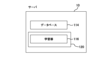
- FIG. 3 shows the main functional configuration of the server 10. As shown in FIG. As shown in the figure, the server 10 has a database 114 and a management section 120 .
- the database 114 is stored in the main storage device 102 or the auxiliary storage device 103 of the server 10. Data sets D and D1 used for machine learning are stored in the database 114 (FIG. 5).
- Data sets D and D1 hold a plurality of combinations in which images R1 to R9 and relative positions L1 to L9 are associated with numbers. A method for generating the data sets D and D1 will be described later.
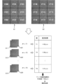
- Images R1 to R9 are images obtained by dividing an image R obtained by photographing living tissue such as cells with the imaging unit 46 as shown in FIG. 8 into 3 ⁇ 3.
- Relative positions L1 to L9 indicate relative positions in the Z-axis direction of the focal point F of the objective lens 31 with respect to the focus position FP (FIG. 10) of the sample (image R) shown in the images R1 to R9.
- the in-focus position FP indicates the Z position at which the sample can be photographed in focus when the focal point F is positioned.
- the relative positions L1-L9 indicate how much the sample or the objective lens 31 should be moved up or down in order to capture an image of the sample in focus.
- the in-focus position FP and the relative positions L1 to L9 are specified based on the Z position signal of the objective lens 31.
- the server 10 also has functions such as an operating system, a file system, a device driver, and a DBMS (DataBase Management System).
- functions such as an operating system, a file system, a device driver, and a DBMS (DataBase Management System).
- the management unit 120 performs processing executed by the server 10, such as acquisition and management of images.
- the functions of the management unit 120 are realized by the processor 101 of the server 10 reading and executing a program stored in the main storage device 102 or the auxiliary storage device 103 of the server 10 .
- Management unit 120 includes learning device 116 .
- the learning device 116 can learn the feature quantity of the input image.
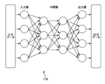
- the learning device 116 constructs a neural network that outputs an estimation result of the relative position of the focal point F of the objective lens 31 with respect to the in-focus position FP for the input image.
- the neural network is a deep convolutional neural network (DCNN).
- the learning device 116 has an input layer that accepts image input, an output layer that outputs estimation results of the target element, and an intermediate layer that extracts the feature amount of the input image (FIG. 4).
- Each of the input layer, the output layer, and the intermediate layer has nodes (indicated by white circles in the figure), and the nodes of these layers are connected by edges (indicated by arrows in the figure).
- edges indicated by arrows in the figure. Note that the configuration of the learning device 116 shown in FIG. 4 is an example, and the number of nodes and edges, the number of intermediate layers, and the like can be changed as appropriate.
- the processing of the information processing system 1 includes two types of processing: learning processing and estimation processing.
- processing executed by the management unit 120 of the server 10 may be simply described as being executed by the "server 10".
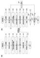
- the well plate P on which the sample is placed is placed on the microscope device 30 (S1).
- the management unit 120 sets the aperture stop 33 of the microscope device 30 to a smaller aperture diameter than the open state (S3). In particular, it is desirable to narrow down to the minimum diameter.
- a point light source may be arranged at the position of the aperture stop 33 and a small light source such as a point light source may be used.
- the pupil diaphragm on the detection lens side may be narrowed down.
- the on-pupil stop is desirably positioned conjugate with the aperture stop. Also, a diaphragm placed at the exit pupil position may be used instead of the aperture diaphragm adjustment.
- the depth of focus of the objective lens 31 is extended, and the range of Z positions within which the image of the sample can be clearly captured increases (FIG. 7). Moreover, the amount of change in contrast with respect to the change in the Z position of the focus F also increases. Therefore, it becomes easier to grasp the distance between the focal point F and the in-focus position FP of the sample.
- the management unit 120 causes the microscope device 30 to perform Z-stack imaging of the sample (S5).
- the microscope device 30 captures the sample multiple times while shifting the Z position of the objective lens 31 by ⁇ Z within a predetermined range, and acquires multiple images R.
- the range in which the sample is photographed can be set by the user, and as an example, it can be a Z position range of ⁇ 300 micrometers ( ⁇ m) from the reference position.
- the moving amount ⁇ Z of the objective lens 31 is +20 ⁇ m in the example of this description, and includes information on the moving direction and moving amount of the objective lens 31 . Note that ⁇ Z is not limited to +20 ⁇ m, and can be set to any value such as ⁇ 2 ⁇ m or +10 ⁇ m.
- the management unit 120 performs preprocessing on the multiple images R acquired by shooting (S7).
- each image R is divided into nine to generate nine images R1 to R9 (FIG. 8).
- the management unit 120 analyzes the contrast of the images R1 to R9 obtained by photographing the samples, and calculates the relative positions L1 to L9 of the focal point F with respect to the in-focus position FP of the image R in the Z-axis direction for each of the images R1 to R9.
- Calculate in The in-focus position FP is obtained by calculating the Z-position of the focal point F when taking the image with the minimum contrast.
- the relative positions L1 to L9 are expressed as numerical values obtained by adding plus/minus signs indicating up and down to distances in the Z direction.
- the images R1 to R9 and the relative positions L1 to L9 are associated with each other and saved as a data set D (S9, FIG. 5).
- step S9 the management unit 120 causes the learning device 116 to learn using the data acquired in step S9 as teacher data (S11). More specifically, the management unit 120 extracts two images arranged in the shooting order (shown as No. in the data set D) from each of the images R1 to R9, and calculates the relative positions L1 to L9 corresponding to these two images. Save as a label (Fig. 5(b), data set D1). In other words, for example, No. 1 and No.
- the photographed image R of No. 2 is a set of two images (R1 to R9) each showing the same position of the sample, and the Z position at the time of photographing differs by ⁇ Z. For the label associated with each set of images R1-R9, the higher or lower relative position associated with each of the two images is always selected.
- the label with the larger value is always selected.
- data set D and data set D1 in FIG. 1 and No. 2 sets of images R1 have No. If the value of the relative position L1 of No. 1 is no. 2 and No. In the image R1 of the set of 3, No. 2 relative position L1 values are labeled.
- a combination of the two images stored in the data set D1 and the associated labels are both input to the learning device 116.
- the management unit 120 assigns No. 1 to each of the images R1 to R9. Two sheets 1 and 2 are extracted and sequentially input to the learning device 116 together with the label.
- the management unit 120 assigns No. 1 to each of the images R1 to R9. 2 and 3 are extracted and sequentially input to the learning device 116 together with the label. In this manner, the management unit 120 causes the learning device 116 to learn combinations of all the acquired images and labels.
- the learning device 116 functions as a learned model for estimating the position (direction and amount of movement) of the focal point F with respect to the in-focus position FP of the displayed sample for the input image (S13 ).
- the well plate P with the samples placed in the wells W1 is placed on the microscope device 30 (S21). Note that the samples used in the estimation process are not limited to the same samples used in the learning process.
- the management unit 120 sets the aperture stop 33 of the microscope device 30 to a small aperture diameter (S23).
- a small light source such as a point light source may be used instead of adjusting the aperture stop.
- the pupil diaphragm on the detection lens side may be narrowed down.
- step S23 initialization is performed.
- the microscope apparatus 30 identifies the lower surface of the well W1 containing the sample by irradiating the PFS light, and moves the stage 32 so that the focal point F is positioned on the upper surface of the bottom of the well W1 (FIG. 10).
- the management unit 120 causes the microscope device 30 to photograph the sample (S25). After photographing the sample for the first time, the microscope device 30 moves the objective lens 31 by ⁇ Z to perform the second photographing. The management unit 120 acquires two images Q1 and Q2 obtained by photographing from the microscope device 30 .
- the management unit 120 performs preprocessing on the images Q1 and Q2 (S27).
- the images Q1 and Q2 are each divided into 9 to generate images Q11 to Q19 and Q21 to Q22 (FIG. 11).
- step S29 the management unit 120 inputs the images Q11 to Q19 and Q21 to Q22 to the learning device 116 to estimate the position (direction and amount of movement) of the focal point F relative to the in-focus position FP. Specifically, as shown in FIG. 11, the management unit 120 selects a set of images Q11 and Q21, a set of images Q12 and Q22, . A combination of the set of Q29 and two images showing the same portion of the sample is created and designated as combinations T1 to T9. Management unit 120 sequentially inputs combinations T1 to T9 to learning device 116 (FIGS. 9 and 11).
- the learning device 116 estimates and outputs the relative position of the focal point F with respect to the in-focus position FP of the sample for each of the combinations T1 to T9. Note that, in this embodiment, in each of the combinations T1 to T9, the estimation result of the image showing the larger estimated value among the two images forming the combination is output. This is because in the learning process, the relative positions L1 to L9 with the larger values are used as labels for each pair of images R1 to R9.
- the management unit 120 calculates a representative value of the estimation results for the combinations T1 to T9 and outputs it as an estimated position (S31).
- the median value is used (FIG. 11).
- other mathematical processing such as the average value can be used to calculate the representative value.
- the management unit 120 moves the objective lens 31 of the microscope device 30 to change the position of the focal point F based on the estimated position (movement direction and movement amount) obtained as a result of the estimation process, Focus F is adjusted (S33).
- Information on the estimated position obtained as a result of the estimation process may be only the direction of movement, and may be controlled to stop when the objective lens 31 reaches the in-focus position.
- the management unit 120 returns the process to step S25, further narrows the aperture diaphragm 33, and redoes the processes from S25 onwards.
- the management unit 120 changes the sample to be photographed and repeats the estimation process (S39: NO). For example, when the sample used for the estimation process is the sample in the well W1, the microscope apparatus 30 moves the stage 32 to change the target of the estimation process to the sample in the well W2 (FIG. 10). The process is repeated (S37).
- the diameter of a diaphragm such as the aperture diaphragm 33 is reduced, or a point light source is used, and the microscope apparatus 30 equipped with the objective lens 31 is used to Acquisition processing (S25) for acquiring a microscope image R (corresponding to a first microscope image set) by photographing a sample (corresponding to a first subject) a plurality of times while changing the position of the objective lens 31, and
- the microscopic image R is input to the trained learner 116 for estimating the position of the focal point F of the objective lens 31, and the position of the focal point F with respect to the in-focus position FP is estimated to be an estimated position (S27 to S31, estimation process) and a process (S33) of moving the focal point F relative to the sample based on the estimated position.
- the microscope device 30 can quickly focus on the sample and perform in-focus photography.
- the microscope device 30 performs the acquisition process (S25) and the estimation process (S31) with the diameter of the aperture stop 33 as the minimum diameter. Also, when the estimation process (S31) is not appropriate and the subject is out of focus, the process is executed again (S33: NO).
- the aperture stop 33 is preferably positioned closer to the light source than the sample.
- the aperture diameter the minimum diameter
- the depth of focus of the objective lens 31 is extended, and the Z position range of the focal point F in which the image of the sample can be clearly captured increases.
- the amount of change in contrast with respect to the change in the Z position of the focus F also increases. Therefore, it is easy to grasp the distance between the focal point F and the in-focus position FP of the sample.
- the estimation process (S27-S31) includes a process (S27) of dividing the microscope images Q1 and Q2 to generate a plurality of images Q11-Q19 and Q21-Q29 (corresponding to partial images); 116, processing for estimating the position of the focal point F with respect to the in-focus position FP for sets T1 to T9 of images Q11 to Q19 and Q21 to Q29 (S29), and calculating a representative value of the estimated values. , and a process (S31) as an estimated position.
- the change in the image with respect to the movement of the focal point F can be grasped, and the learning device 116 can accurately estimate the distance of the focal point F to the in-focus position FP. .
- learning device 116 grasps changes in images to determine whether focus F moved away from in-focus position FP when multiple images Q1 and Q2 were captured, or whether focus F moved away from in-focus position FP. It is possible to grasp whether it has moved so as to approach to. As a result, the learning device 116 can grasp whether the focal point F is located above or below the in-focus position FP, in addition to simply grasping the distance. Therefore, the learning device 116 can accurately estimate not only the distance but also the relative position of the focal point F with respect to the in-focus position FP.
- the trained model uses a diaphragm with a diameter smaller than the full aperture, changes the position of the objective lens 31 with respect to the sample in the optical axis direction within a predetermined range at predetermined intervals, and photographs the sample a plurality of times.
- An image R (second microscope image) is acquired (S5), the relative position of the focal point of the objective lens 31 with respect to the in-focus position of the sample is calculated in each of the two images R (S9), and the two images R and , and the associated relative positions, are generated by causing the learner 116 to perform machine learning (S11, S13).
- the learned model includes a process of dividing each image of the two images R to generate a plurality of partial images R1 to R9, and an objective lens 31 for each of the sample in-focus positions in the plurality of partial images R1 to R9. are generated by causing the learner 116 to perform machine learning on the teacher data D1 including combinations of the plurality of partial images R1 to R9 and the associated relative positions, and in the combinations, the associated As the relative position, either the larger value or the smaller value is selected from among the relative positions corresponding to the plurality of partial images R1 to R9.
- the learner 116 can determine whether the focus F has moved away from the focus position FP or whether the focus F has moved away from the focus position FP based on changes in the multiple images. It learns whether it has moved closer to the focus position FP. As a result of learning, the learning device 116 functions as a trained model that accurately estimates not only the distance but also the relative position of the focal point F with respect to the in-focus position FP.
- each image can be divided into arbitrary shapes and arbitrary numbers, such as 16 divisions and 32 divisions, without being limited to 9 divisions as in the above embodiment.
- image R, images Q1, and Q2 may be input to learning device 116 as they are without division.
- the number of images input to the learning device 116 is not limited to two in the estimation processing and learning processing.
- three or more input images can be used.
- the relative position of the focal point F with respect to the in-focus position FP in one of the plurality of input images may be used as the label associated with each combination.
- the machine learning method in the above embodiment may be regression or classification. When machine learning by classification is performed, it is possible to perform learning similar to the above and generate an estimation model by performing interpolation between data in post-processing.
- the well plate P on which the sample is placed does not need to be the same for the estimation process and the learning process. It is also possible to prepare a plurality of types of containers for placing samples, perform learning processing, and generate learned models corresponding to containers of various shapes and materials.
- a plurality of terminals are connected to one server 10, and the above functions are exhibited.
- the present invention does not limit the number of servers or the number of terminals, and for example, the functions described above may be realized by only one device. Also, the number of terminals and the number of servers may be further increased. Also, each function does not necessarily have to be implemented by the server 10 or the like, and may be shared by a plurality of devices to implement the function. That is, the present invention does not limit the number of controllers or devices, or the sharing of functions among devices.
Landscapes
- Physics & Mathematics (AREA)
- Optics & Photonics (AREA)
- General Physics & Mathematics (AREA)
- Engineering & Computer Science (AREA)
- Chemical & Material Sciences (AREA)
- Analytical Chemistry (AREA)
- Computer Vision & Pattern Recognition (AREA)
- Multimedia (AREA)
- General Engineering & Computer Science (AREA)
- Microscoopes, Condenser (AREA)
- Focusing (AREA)
- Automatic Focus Adjustment (AREA)
- Studio Devices (AREA)
Priority Applications (6)
| Application Number | Priority Date | Filing Date | Title |
|---|---|---|---|
| EP22929770.0A EP4488738A4 (en) | 2022-03-02 | 2022-03-02 | METHOD, PROGRAM AND DEVICE FOR FOCUS ADJUSTMENT |
| CN202280092856.9A CN118829926A (zh) | 2022-03-02 | 2022-03-02 | 焦点调整方法、程序、装置 |
| JP2024504099A JP7758151B2 (ja) | 2022-03-02 | 2022-03-02 | 焦点調整方法、プログラム、装置 |
| PCT/JP2022/008931 WO2023166624A1 (ja) | 2022-03-02 | 2022-03-02 | 焦点調整方法、プログラム、装置 |
| US18/814,792 US20250076626A1 (en) | 2022-03-02 | 2024-08-26 | Focus adjustment method, program, and apparatus |
| JP2025170947A JP2026010044A (ja) | 2022-03-02 | 2025-10-09 | 焦点調整方法、プログラム、装置 |
Applications Claiming Priority (1)
| Application Number | Priority Date | Filing Date | Title |
|---|---|---|---|
| PCT/JP2022/008931 WO2023166624A1 (ja) | 2022-03-02 | 2022-03-02 | 焦点調整方法、プログラム、装置 |
Related Child Applications (1)
| Application Number | Title | Priority Date | Filing Date |
|---|---|---|---|
| US18/814,792 Continuation US20250076626A1 (en) | 2022-03-02 | 2024-08-26 | Focus adjustment method, program, and apparatus |
Publications (1)
| Publication Number | Publication Date |
|---|---|
| WO2023166624A1 true WO2023166624A1 (ja) | 2023-09-07 |
Family
ID=87883207
Family Applications (1)
| Application Number | Title | Priority Date | Filing Date |
|---|---|---|---|
| PCT/JP2022/008931 Ceased WO2023166624A1 (ja) | 2022-03-02 | 2022-03-02 | 焦点調整方法、プログラム、装置 |
Country Status (5)
| Country | Link |
|---|---|
| US (1) | US20250076626A1 (https=) |
| EP (1) | EP4488738A4 (https=) |
| JP (2) | JP7758151B2 (https=) |
| CN (1) | CN118829926A (https=) |
| WO (1) | WO2023166624A1 (https=) |
Citations (5)
| Publication number | Priority date | Publication date | Assignee | Title |
|---|---|---|---|---|
| JPH04330411A (ja) * | 1991-05-02 | 1992-11-18 | Olympus Optical Co Ltd | 自動合焦装置 |
| JPH0875980A (ja) * | 1994-09-02 | 1996-03-22 | Olympus Optical Co Ltd | 顕微鏡用自動焦点検出装置 |
| JPH11264937A (ja) * | 1998-03-18 | 1999-09-28 | Olympus Optical Co Ltd | 顕微鏡 |
| JP2020060602A (ja) | 2018-10-04 | 2020-04-16 | キヤノン株式会社 | 焦点調整装置およびその制御方法ならびにプログラム |
| JP2020148856A (ja) * | 2019-03-12 | 2020-09-17 | 株式会社Screenホールディングス | フォーカス調整方法、画像取得方法、および画像取得装置 |
Family Cites Families (3)
| Publication number | Priority date | Publication date | Assignee | Title |
|---|---|---|---|---|
| JP2009180991A (ja) * | 2008-01-31 | 2009-08-13 | Nikon Corp | 焦点調節装置及び顕微鏡装置 |
| EP4336238A4 (en) * | 2021-07-19 | 2025-05-14 | Hamamatsu Photonics K.K. | Focal position estimation system, focal position estimation method, focal position estimation program, semiconductor inspection system and biological observation system |
| WO2023002678A1 (ja) * | 2021-07-19 | 2023-01-26 | 浜松ホトニクス株式会社 | 特徴量出力モデル生成システム、特徴量出力モデル生成方法、特徴量出力モデル生成プログラム及び特徴量出力モデル |
-
2022
- 2022-03-02 EP EP22929770.0A patent/EP4488738A4/en active Pending
- 2022-03-02 JP JP2024504099A patent/JP7758151B2/ja active Active
- 2022-03-02 WO PCT/JP2022/008931 patent/WO2023166624A1/ja not_active Ceased
- 2022-03-02 CN CN202280092856.9A patent/CN118829926A/zh active Pending
-
2024
- 2024-08-26 US US18/814,792 patent/US20250076626A1/en active Pending
-
2025
- 2025-10-09 JP JP2025170947A patent/JP2026010044A/ja active Pending
Patent Citations (5)
| Publication number | Priority date | Publication date | Assignee | Title |
|---|---|---|---|---|
| JPH04330411A (ja) * | 1991-05-02 | 1992-11-18 | Olympus Optical Co Ltd | 自動合焦装置 |
| JPH0875980A (ja) * | 1994-09-02 | 1996-03-22 | Olympus Optical Co Ltd | 顕微鏡用自動焦点検出装置 |
| JPH11264937A (ja) * | 1998-03-18 | 1999-09-28 | Olympus Optical Co Ltd | 顕微鏡 |
| JP2020060602A (ja) | 2018-10-04 | 2020-04-16 | キヤノン株式会社 | 焦点調整装置およびその制御方法ならびにプログラム |
| JP2020148856A (ja) * | 2019-03-12 | 2020-09-17 | 株式会社Screenホールディングス | フォーカス調整方法、画像取得方法、および画像取得装置 |
Non-Patent Citations (1)
| Title |
|---|
| See also references of EP4488738A4 |
Also Published As
| Publication number | Publication date |
|---|---|
| JPWO2023166624A1 (https=) | 2023-09-07 |
| EP4488738A4 (en) | 2026-01-07 |
| JP7758151B2 (ja) | 2025-10-22 |
| JP2026010044A (ja) | 2026-01-21 |
| CN118829926A (zh) | 2024-10-22 |
| EP4488738A1 (en) | 2025-01-08 |
| US20250076626A1 (en) | 2025-03-06 |
Similar Documents
| Publication | Publication Date | Title |
|---|---|---|
| US20220260826A1 (en) | Computational microscopy based-system and method for automated imaging and analysis of pathology specimens | |
| JP7661462B2 (ja) | 顕微鏡システム、プログラム、及び、投影画像生成方法 | |
| JP6453298B2 (ja) | 細胞診標本を観察および解析するためのシステムおよび方法 | |
| US11113506B2 (en) | Method for providing an evaluation means for at least one optical application system of a microscope-based application technology | |
| US10477097B2 (en) | Single-frame autofocusing using multi-LED illumination | |
| US12301990B2 (en) | Deep learning model for auto-focusing microscope systems | |
| CN107850754A (zh) | 具有快速样本自动聚焦的成像组件 | |
| CN112714886B (zh) | 显微镜系统、投影单元以及图像投影方法 | |
| US20120249770A1 (en) | Method for automatically focusing a microscope on a predetermined object and microscope for automatic focusing | |
| JP2022109258A (ja) | 人間工学的視野に基づく光学顕微鏡システム | |
| CN111656247A (zh) | 一种细胞图像处理系统、方法、自动读片装置与存储介质 | |
| US20200074628A1 (en) | Image processing apparatus, imaging system, image processing method and computer readable recoding medium | |
| JP7758151B2 (ja) | 焦点調整方法、プログラム、装置 | |
| US10475198B2 (en) | Microscope system and specimen observation method | |
| JP7090171B2 (ja) | 画像処理装置の作動方法、画像処理装置、及び画像処理装置の作動プログラム | |
| Islam et al. | Development of Low Cost, Automated Digital Microscopes Allowing Rapid Whole Slide Imaging for Detecting Malaria | |
| JP7767182B2 (ja) | 解析方法および解析装置 | |
| Mallick et al. | Real-time, automated, multiobjective, cloud computing whole slide imaging device | |
| Pechprasarn et al. | Low-cost instrumentation of Automated Whole–slide Microscope for Biomedical Imaging | |
| JP2015220625A (ja) | 画像取得装置および画像取得方法 | |
| Oyibo et al. | An automated slide scanning system for membrane filter imaging in diagnosis of urogenital schistosomiasis | |
| SE2250140A1 (en) | Imaging apparatus and method for determning a focal point of a well-plate | |
| Zheng | An investigation into advanced digital microscopic technologies | |
| CN118151361A (zh) | 一种样本图像分析设备和样本图像的成像方法 | |
| JP2021021823A (ja) | 顕微鏡、顕微鏡で試料を撮像する方法、プログラム、および制御装置 |
Legal Events
| Date | Code | Title | Description |
|---|---|---|---|
| 121 | Ep: the epo has been informed by wipo that ep was designated in this application |
Ref document number: 22929770 Country of ref document: EP Kind code of ref document: A1 |
|
| ENP | Entry into the national phase |
Ref document number: 2024504099 Country of ref document: JP Kind code of ref document: A |
|
| WWE | Wipo information: entry into national phase |
Ref document number: 202280092856.9 Country of ref document: CN |
|
| WWE | Wipo information: entry into national phase |
Ref document number: 2022929770 Country of ref document: EP |
|
| NENP | Non-entry into the national phase |
Ref country code: DE |
|
| ENP | Entry into the national phase |
Ref document number: 2022929770 Country of ref document: EP Effective date: 20241002 |