WO2023166546A1 - ステレオ画像処理装置 - Google Patents
ステレオ画像処理装置 Download PDFInfo
- Publication number
- WO2023166546A1 WO2023166546A1 PCT/JP2022/008530 JP2022008530W WO2023166546A1 WO 2023166546 A1 WO2023166546 A1 WO 2023166546A1 JP 2022008530 W JP2022008530 W JP 2022008530W WO 2023166546 A1 WO2023166546 A1 WO 2023166546A1
- Authority
- WO
- WIPO (PCT)
- Prior art keywords
- image processing
- image
- sensor
- stereo image
- stereo
- Prior art date
- Legal status (The legal status is an assumption and is not a legal conclusion. Google has not performed a legal analysis and makes no representation as to the accuracy of the status listed.)
- Ceased
Links
Images













Classifications
-
- G—PHYSICS
- G01—MEASURING; TESTING
- G01C—MEASURING DISTANCES, LEVELS OR BEARINGS; SURVEYING; NAVIGATION; GYROSCOPIC INSTRUMENTS; PHOTOGRAMMETRY OR VIDEOGRAMMETRY
- G01C3/00—Measuring distances in line of sight; Optical rangefinders
- G01C3/02—Details
- G01C3/06—Use of electric means to obtain final indication
- G01C3/08—Use of electric radiation detectors
- G01C3/085—Use of electric radiation detectors with electronic parallax measurement
-
- H—ELECTRICITY
- H04—ELECTRIC COMMUNICATION TECHNIQUE
- H04N—PICTORIAL COMMUNICATION, e.g. TELEVISION
- H04N13/00—Stereoscopic video systems; Multi-view video systems; Details thereof
- H04N13/20—Image signal generators
- H04N13/204—Image signal generators using stereoscopic image cameras
- H04N13/207—Image signal generators using stereoscopic image cameras using a single two-dimensional [2D] image sensor
Definitions
- the present invention relates to a stereo image processing device.
- a stereo image processing device (hereinafter referred to as a stereo camera) is known as a device for three-dimensionally recognizing objects.
- a stereo camera detects the parallax between multiple images based on trigonometry by using differences in how images are captured by multiple cameras placed at different positions, and uses that parallax to detect the depth and position of an object. and can accurately detect the position of the object.
- Patent document 1 and patent document 2 are proposed for such a problem.
- Japanese Patent Laid-Open No. 2002-200022 acquires an image having parallax with respect to a subject in order to solve the problem of providing an inexpensive stereo camera that is not affected by changes in lens distortion and changes in mounting position of a fixture due to changes in temperature.
- a polarization multiplexing means including a cross prism 205 and a polarizing beam splitter that superimposes optical paths of two images having parallax with different polarization directions in orthogonal directions, and luminance in at least two polarization directions and a lens 204 for forming the superimposed images on the imaging device 202 .
- Patent Document 2 addresses the problem of obtaining a plurality of images with sufficient parallax with a relatively simple configuration using a single imaging means in a three-dimensional imaging apparatus.
- one imaging element 1 a pair of imaging element side mirrors 5a and 5b provided so as to face obliquely outwards with respect to two imaging areas 1a and 1b different from each other, and correspondingly to the outside thereof.
- a pair of subject-side mirrors 6a and 6b arranged to face obliquely forward and reflecting light from the subject to the corresponding image sensor-side mirrors 5a and 5b, and the same mirrors reflected by these 5a, 5b, 6a and 6b.
- Patent Documents 1 and 2 have at least three problems. Regarding the first problem, Patent Documents 1 and 2 have a single camera module by streamlining the optical system. On the other hand, Patent Document 1 uses an expensive prism, and Patent Document 2 uses four mirror portions, so the problem of cost still remains.
- Patent Document 1 and Patent Document 2 require two reflections, which increases the length of the optical path in the stereo camera.
- the third issue is environmental resistance. As the mirror rotates, the reflected beam rotates twice the amount of mirror rotation. Therefore, an increase in the number of reflections is not desirable from the standpoint of environmental resistance.
- the present invention has been made in view of the above problems, and provides a stereo image processing device with a simple structure.
- a stereo image processing apparatus for processing a stereo image, which includes a first reflecting section for reflecting an image of an object, a second reflecting section for reflecting an image of an object, and a camera for photographing the object.
- the sensor of the camera has at least three sensor areas, a first sensor area, a second sensor area, and a third sensor area, and the third sensor area includes the first sensor area and the second sensor area.
- light from the object and reflected by the first reflector enters the first sensor region, and the second sensor region receives the light from the object
- a stereo image processing apparatus characterized in that light from an object and reflected by a second reflecting portion is incident thereon.
- stereo image processing device it is possible to provide a stereo image processing device with a simple structure. According to the embodiments of the present invention, specifically, a low-cost, compact, and highly environment-resistant stereo image processing apparatus can be realized.
- FIG. 1 is a configuration diagram showing an example of an optical system of a stereo image processing apparatus according to related art of the present invention
- FIG. FIG. 4 shows rays as viewed from the positive position of the vertical axis
- FIG. 4 shows rays as viewed from the positive position on the horizontal axis
- region by each light ray in FIG. 2A and FIG. 2B. 4 is a diagram showing an example of an image P0 obtained by detecting an object 5 with a sensor 100 in the camera module 2;
- FIG. 10 is a diagram showing a stereoscopic common area (flat coincidence) of the image P3 and the image P4;
- FIG. 10 is a diagram showing a stereoscopic common area (plane mismatch) between the image P3 and the image P4;
- 4A and 4B are diagrams showing examples of the shape of a plane mirror;
- FIG. FIG. 4 is a diagram showing an example of an image when sensors are arranged in the vertical direction;
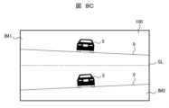
- FIG. 4 is a diagram showing an example of an image when the stereo camera is rotated 90 degrees with respect to the depth axis;
- FIG. 4 is a diagram showing an example of an image when the stereo camera is rotated 90 degrees with respect to the depth axis;
- FIG. 10 is a diagram showing a stereoscopic common area (flat coincidence) of the image P3 and the image P4;
- FIG. 10 is a diagram showing a stereoscopic common area (plane mismatch) between the image P3 and the image P4;
- FIG. 5 is a diagram showing an example of detecting an image outside the housing through a glass plate or the like; 3 is a three-dimensional diagram showing an example of arrangement of structural parts of the stereo camera 10.
- FIG. FIG. 2 is a plan view showing an arrangement example of structural parts of the stereo camera 10;
- FIG. 4 is a configuration diagram showing another example of the optical system of the stereo image processing device according to the related art of the present invention;
- FIG. 4 is a diagram showing an example of an image when sensors are arranged in the vertical direction;
- FIG. 4 is a diagram showing an example of an image when the stereo camera is rotated 90 degrees with respect to the depth axis;
- FIG. 4 is a diagram showing an example of an image when the stereo camera is rotated 90 degrees with respect to the depth axis;
- FIG. 2 is a configuration diagram showing an example of the optical system of the stereo image processing apparatus according to the first embodiment;
- 4A and 4B are diagrams showing images detected by the stereo image processing apparatus according to the first embodiment;
- FIG. 4 is a configuration diagram showing another example of the optical system of the stereo image processing apparatus according to the first embodiment;
- FIG. 4 is a configuration diagram showing another example of the optical system of the stereo image processing apparatus according to the first embodiment;
- FIG. 4 is a diagram showing an example of an image when sensors are arranged in the vertical direction;
- FIG. 4 is a diagram showing an example of an image when the stereo camera is rotated 90 degrees with respect to the depth axis;
- FIG. 4 is a diagram showing an example of an image when the stereo camera is rotated 90 degrees with respect to the depth axis;
- FIG. 11 is a configuration diagram showing an example of an optical system of a stereo image processing apparatus according to Embodiment 4;
- FIG. 11 is a diagram showing images detected by the stereo image processing apparatus according to the fourth embodiment;
- FIG. 4 is a diagram showing an example of an image when sensors are arranged in the vertical direction;
- FIG. 4 is a diagram showing an example of an image when the stereo camera is rotated 90 degrees with respect to the depth axis;
- FIG. 4 is a diagram showing an example of an image when the stereo camera is rotated 90 degrees with respect to the depth axis;
- FIG. 4 is a configuration diagram showing another example of the optical system of the stereo image processing device according to the related art of the present invention; The figure which shows the detected image of the stereo image processing apparatus which concerns on related technology of this invention.
- FIG. 4 is a diagram showing an example of an image when sensors are arranged in the vertical direction;
- FIG. 4 is a diagram showing an example of an image when the stereo camera is rotated 90 degrees with respect to the depth axis;
- FIG. 4 is a diagram showing an example of an image when the stereo camera is rotated 90 degrees with respect to the depth axis;
- FIGS. 14 to 21 the related technical matters on which the present invention is based will be described prior to describing the embodiments, and the embodiments of the present invention will be described. shall be performed using FIGS. 14 to 21.
- FIG. Some of the related technologies described below include technical matters that are not publicly known.
- FIG. 1 is a diagram showing a configuration example of an optical system of a stereo camera 10 according to the technology related to the present invention.
- the stereo camera 10 is composed of a camera module 2 composed of a lens 99 and a sensor 100, two plane mirrors 40R and 40L, and further includes an arithmetic unit 3 for processing images acquired by the camera module 2.
- the principal ray of the camera module 2 is arranged so as to intersect the boundary between the plane mirrors 40R and 40L at the distance d.
- the stereo camera 10 according to the related technology of the present invention is characterized in that the imaging direction of the stereo camera 10 and the direction in which the camera module 2 faces are substantially reversed because the number of mirror reflections is one. There is Moreover, since the number of reflections of the mirror is one, there is an effect that the environmental resistance is higher than that of Patent Documents 1 and 2.
- a related technology stereo camera shall measure the distance in the depth direction.
- the stereo camera 10 of the related art detects images of two viewpoints with one camera module, two optical axes OA directed to two virtual viewpoints (not shown) are defined.
- the optical axis OA1 reflecting the plane mirror 40R and the optical axis OA2 reflecting the plane mirror 40L are used.
- the optical axis OA1 and the optical axis OA2 outside the stereo camera 10 are substantially parallel.
- the optical axis outside the stereo camera 10 is the optical axis before being reflected by the plane mirrors 40R and 40L.
- the optical axis in the stereo camera 10 is the optical axis between the plane mirrors 40R and 40L and the camera module 2.
- the related technology is "a stereo image processing device for processing stereo images, comprising at least one or more reflection units 40R and 40L for reflecting an image of an object, A single camera 99 for photographing an object to be photographed is provided, and the camera 99 detects an image reflected only once by the reflecting portions 40R and 40L.
- the plane mirror 40R and the plane mirror 40L can be configured as an integral body, but they have two reflecting portions.
- FIG. 2A shows light rays when viewed in a cross section consisting of optical axes OA1 and OA2 outside the stereo camera 10 (viewed from the positive position of the vertical axis), and FIG. 2B shows light rays on the optical axis OA2 and outside the stereo camera 10.
- Light rays are shown when viewed in a cross section perpendicular to the cross section formed by the optical axis OA1 and the optical axis OA2 (viewed from the positive position on the horizontal axis).
- dotted lines indicate rays directed toward the camera module 2 .
- the stereo camera 10 is installed on the road 9 (or a vehicle not shown), and the distance to the vehicle 5 traveling on the road 9 is , the distance to the vehicle in front is taken in the depth direction, and the arrangement direction of the two plane mirrors is taken in the horizontal direction.
- this layout example will be used as a reference layout example, and when the layout example is different, it will be illustrated and indicated as appropriate.
- the light beams of vertical and horizontal angles of view are reflected by the plane mirrors 40L and 40R, pass through the lens 99 in the camera module 2, and form an image on the sensor 100. do.
- a line obtained by extending a light ray incident on the camera module 2 and directed to the flat mirror 40R and the flat mirror 40L is indicated by a dashed line.
- a point at which the dashed-dotted lines substantially intersect is defined as a virtual viewpoint VP1 for the plane mirror 40R and a virtual viewpoint VP2 for the plane mirror 40L.
- the virtual viewpoints VP1 and VP2 indicate effective positions of the camera module 2. This is similar to detection from the virtual viewpoints VP1 and VP2, respectively, since the light rays are reflected by the plane mirrors 40R and 40L. Strictly speaking, the virtual viewpoints VP1 and VP2 correspond to the pupil positions of the lens 99 of the camera module 2 . In an actual lens, the pupil position differs depending on the angle of view, so the virtual viewpoints VP1 and VP2 do not overlap at one point. It can be considered as one point.
- the stereo camera 10 of the related art has a plane formed by an optical axis OA1 and an optical axis OA2 inside the stereo camera 10 and a plane formed by an optical axis OA1 and an optical axis OA2 outside the stereo camera 10. It is characterized in that the angle formed is a predetermined angle ⁇ . If the two planes were to coincide, the camera module itself would be imaged onto the sensor, reducing the number of available pixels. Therefore, by setting the angle formed by these two surfaces to the predetermined angle ⁇ , the image in the depth direction can be efficiently detected by reflecting the plane mirror only once.
- the pupil position of the camera module 2 is arranged below the plane formed by the normal 40MA of the plane mirror 40L and the normal (not shown) of the plane mirror 40R. be done.
- Figures 3A and 3B are diagrams in which the areas are divided by the light rays in Figures 2A and 2B.
- a region composed of light rays incident on the plane mirror 40R (first reflecting portion) and the plane mirror 40L (second reflecting portion) is a first region R1 and incident on the plane mirror 40R (first reflecting portion).
- a second region R2 is defined by a line (one-dot chain line) obtained by extending a light ray extending to a virtual viewpoint VP1 (first virtual viewpoint).
- a region formed by a line (chain line) when extended to VP2 (second virtual viewpoint) is a third region R3, and a minimum convex region including the second region R2 and the third region R3 is a fourth region.
- the lens pupil position of the camera module 2 is arranged outside the region R composed of the first region R1 and the fourth region R4.
- the camera module 2 is arranged outside the area formed by the first area R1 and the fourth area R4 in the vertical direction.
- FIG. 4 shows an image P0 of the object 5 detected by the sensor 100 in the camera module 2.
- FIG. It is assumed that the object 5 is on the road 9 parallel to the cross section along the horizontal and depth axes of FIG.
- the image P0 is divided into two horizontal image areas IM1 (first sensor area) and IM2 (second sensor area) by the dividing line SL.
- the road surface 9 is detected obliquely by the sensor. This is because the plane formed by the optical axes OA1 and OA2 inside the stereo camera 10 shown in FIG. 2B and the plane formed by the optical axes OA1 and OA2 outside the stereo camera 10 form a predetermined angle ⁇ .
- the stereo camera 10 of the related art is characterized in that the image area IM1 and the image area IM2 in the image are tilted in opposite directions. It should be noted that the tilting direction differs depending on the arrangement position of the camera module 2 . For example, when it is arranged below the region R composed of the first region R1 and the fourth region R4, it becomes as shown in FIG. When it is arranged on the upper side, the central portion of the road surface 9 has a convex shape.
- the stereo camera 10 can obtain the required image of the camera module 2.
- the angle is ( ⁇ +180) degrees or more
- the base length B is 2 ⁇ d ⁇ sin(180 ⁇ )
- the required mirror size is d ⁇ sin(90 ⁇ /2)+cos(90 ⁇ / 2) ⁇ tan( ⁇ /2+90) ⁇ or more.
- the equal sign holds for the required angle of view and the required mirror size when the mirror surfaces of the plane mirror 40R and the plane mirror 40L are connected and the predetermined angle ⁇ is brought close to zero. As this condition is deviated from, the required angle of view and the required mirror size must be increased.
- the processing device and processing method of the stereo camera 10 will be described with reference to FIG.
- the stereo camera 10 is mounted on a vehicle such as an automobile or a motorcycle, and is used to detect the distance from the vehicle to surrounding three-dimensional objects (other automobiles, buildings, pedestrians, etc.).
- a vehicle such as an automobile or a motorcycle
- three-dimensional objects other automobiles, buildings, pedestrians, etc.
- a case where the stereo camera 10 is mounted on a vehicle will be described below as an example, but the present invention is not limited to this.
- the stereo camera 10 is configured to detect surrounding three-dimensional objects and issue an alarm as necessary.
- the calculation unit 3 in the stereo camera 10 is configured including, for example, an image processing unit 200, a stereo parallax image generation unit 300, a stereoscopic three-dimensional object detection unit 500, and an alarm control unit 700.
- the sensor 100 in the camera module 2 detects the image P0 illustrated in FIG.
- the image P0 is given to the image processing unit 200, which is the first processing function of the calculation unit 3, and the image P0 is divided into two images P1 (first detection image) and image P2 (second detection image).
- the image processing unit 200 further includes affine processing means 20a and 20b, luminance correction means 21a and 21b, pixel interpolation means 22a and 22b, and luminance information generation means 23a and 23b.
- the image processing unit 200 applies these predetermined image processes to each of the images P1 and P2, and supplies them to the stereo parallax image generation unit 300 .
- the affine processing means 20a applies affine processing to the image P1.
- Affine processing is, for example, linear coordinate transformation processing, but may include non-linear calculations.
- the affine processing means 20a acquires the image P3 (third image).
- the affine processing means 20b obtains an image P4 (fourth image) by applying affine processing to the image P2.
- the tilt of the image shown in FIG. 3 is corrected by the affine processing means 20a and 20b.
- inclination processing in opposite directions is performed on the image P1 (first detection image) and the image P2 (second detection image).
- the matching process can be executed for each line, so that the parallax process can be easily executed.
- the luminance correction means 21a corrects the luminance of each pixel of the image P3. For example, the luminance of each pixel in the image P3 is corrected based on the difference in gain of each pixel in the image P3. Similarly, the luminance correction means 21b corrects the luminance of each pixel of the image P4.
- the pixel interpolation means 22a performs demosaicing processing on the image P3. For example, a RAW image is converted into a color image. Similarly, the pixel interpolation means 22b performs demosaicing processing on the image P4.
- the luminance information generating means 23a generates luminance information of the image P3. For example, information representing a color image is converted into luminance information for generating a parallax image. Similarly, the luminance information generating means 23b generates luminance information of the image P4.
- the stereo parallax image generation unit 300 generates a stereo parallax image using the image of the stereo vision common area among the obtained images P3 and P4.
- the stereoscopic common area will be described.
- FIGS. 6A and 6B show the stereoscopic common area of the image P3 and the image P4 in the cases of plane match and plane mismatch.
- FIG. 6A shows a case where the plane formed by the optical axes OA1 and OA2 inside the stereo camera 10 and the plane formed by the optical axes OA1 and OA2 outside the stereo camera 10 match.
- the number of pixels that can be used is reduced, but for the sake of simplicity, the reduction in the number of pixels will not be discussed here.
- FIG. 6B shows the case where the plane formed by the optical axes OA1 and OA2 inside the stereo camera 10 and the plane formed by the optical axes OA1 and OA2 outside the stereo camera 10 form a predetermined angle ⁇ (plane mismatch ).
- the image P3 indicated by the dotted line and the image P4 indicated by the dashed line are tilted in the opposite direction to FIG. 6A. Therefore, it can be seen that the stereoscopic common area CA of the image P3 and the image P4 indicated by hatched areas changes according to the angle ⁇ . From the viewpoint of the stereoscopic common area, it is desirable that the angle ⁇ be small. However, the angle ⁇ may be set according to a request such as detecting the lower side in one of the images detected in the image P3 or the image P4.
- the stereo parallax image generation unit 300 in FIG. 5 generates stereo parallax images by using the image of the stereo vision common area CA among the images P3 and P4.
- the stereo parallax image generation unit 300 includes an exposure adjustment unit 210 and a sensitivity adjustment unit 220, and can execute feedback control to the camera module 2 regarding the exposure amount, sensitivity, etc. of the camera module.
- the stereo parallax image generation unit 200 further includes a geometric correction unit 230 that performs geometric correction of two images, a matching unit 240 that performs matching processing between the left and right images, and a pixel shift amount calculation unit 260 that calculates the pixel shift amount.
- a geometric correction unit 230 that performs geometric correction of two images
- a matching unit 240 that performs matching processing between the left and right images
- a pixel shift amount calculation unit 260 that calculates the pixel shift amount.
- the pixel shift amount calculator 260 constitutes a pixel shift correction processor together with the affine processors 20a and 20b.
- the stereoscopic three-dimensional object detection unit 500 detects a three-dimensional object in the stereoscopic region according to the stereo parallax image generated by the stereo parallax image generation unit 200 .
- Stereo matching is applied to the detected three-dimensional object to detect parallax, and the type of three-dimensional object (pedestrian, bicycle, vehicle, building, etc.) is identified.
- the types to be used for preventive safety are specified.
- the detection result can be used for follow-up control of the preceding vehicle and emergency braking control.
- emergency brake control or alarm control can be executed.
- the alarm control unit 700 can perform more appropriate alarms and control.
- a stereo camera can be realized with only one camera module and two plane mirrors.
- the conventional problems of low cost, small size, and environmental resistance can be solved.
- the detection method does not depend on the projection method of the lens.
- central projection (ftan ⁇ ), which is the projection of a normal lens
- orthographic projection (f sin ⁇ )
- equidistant projection (f ⁇ )
- isostereographic projection (2fsin( ⁇ /2)
- stereographic projection (2ftan( ⁇ /2)
- the two optical axes OA1 and OA2 on the sensor are equidistant from the lens optical axis (the axis extending from the lens center), so the resolution is the same.
- the images in the right (or left) regions of the two images P3 and P4 have different lens resolutions because the distances from the lens optical axis do not match.
- parallax errors are likely to occur at different resolutions. For example, it is possible to reduce the parallax error by performing processing using a digital filter that changes the resolution according to the angle of view. As a result, the accuracy of distance measurement decreases.
- the resolution is constant regardless of the position from the lens optical axis. Therefore, the right (or left) resolutions of the two images P3 and P4 are the same. As a result, stereo vision can be realized most efficiently.
- the rotation deviation angle can be corrected as a fixed value for all images in the detected image.
- the shape of the mirror is not limited.
- the plane mirror may have a shape as shown in FIG. 7 for miniaturization.
- the reason for such a shape is that the required mirror size differs depending on the angle of view of the distance between the pupil position of the camera module 2 and the plane mirror 40L (or the plane mirror 40R). For example, when the distance between the lens pupil position of the lens 99 in the camera module 2 and the plane mirror 40L (or the plane mirror 40R) is short, the mirror section is small, and when it is far, the mirror section is large.
- the sensor 100 may be arranged in the vertical direction as shown in FIG. 8A.
- the angle of view in the vertical direction (vertical direction in the figure) can be widened.
- the stereo camera may be rotated, for example, by 90 degrees with respect to the depth axis.
- images such as those shown in FIGS. 8B and 8C are obtained.
- Parallax in the horizontal direction is detected in the cases of FIGS. 4 and 8A, but parallax in the vertical direction is detected in the cases of FIGS. 8B and 8C.
- FIG. 8B has the advantage that the angle of view in the vertical direction can be widened.
- FIG. 8C has the advantage that the horizontal angle of view can be widened.
- FIGS. 4 and 8B are advantageous from the viewpoint of high-speed detection.
- parallax is detected using the detection signal in the longitudinal direction. Therefore, the difference in detection time between two images for which parallax is detected is small.
- the deviation in detection time becomes larger than in FIGS. 4 and 8B. If the difference in detection time is small, high distance measurement accuracy can be obtained when a car or two-wheeled vehicle equipped with the stereo camera 10 is traveling at high speed.
- the two viewpoints on the sensor 100 are equally divided from the viewpoint of increasing the angle of view of stereoscopic vision, but the invention is not limited to this.
- the angle of view of the virtual viewpoint VP1 or the virtual viewpoint VP2 can be increased.
- the plane mirror 40R and the plane mirror 40L may be horizontally shifted with respect to the camera module.
- the two mirrors were flat.
- the mirror may be curved to widen the field of view. With such a configuration, a wide-angle stereo camera can be realized without using a wide-angle lens.
- the angle between the plane formed by the optical axes OA1 and OA2 inside the stereo camera 10 and the plane formed by the optical axes OA1 and OA2 outside the stereo camera 10 can be reduced.
- the inclination of the two images can be reduced, and the stereoscopic common area CA can be increased.
- the same effect can be obtained whether the direction of the curved surface is one-dimensional or two-dimensional.
- the accuracy of distance measurement is higher with flat mirrors than with curved mirrors.
- the reason for this is the effect of aberration.
- the ray bundle forming one pixel on the sensor has different inclinations, and thus aberration occurs. This reduces resolution.
- the curved mirror has low robustness against rotational and positional deviations of the mirror. Plane mirrors are almost position independent, while curved mirrors are highly position dependent. Therefore, in consideration of practical use, a highly robust plane mirror is desirable.
- the optical system may be partially or wholly placed in the housing and an image outside the housing may be detected through a glass plate or the like.
- the glass plate may be tilted with respect to the optical axis in consideration of the influence of stray light reflected by the glass plate.
- the reflected stray light can be efficiently avoided by tilting the glass plate 65 from 90 degrees with respect to the plane formed by the optical axes OA1 and OA2 outside the stereo camera 10.
- the horizontal angle of view is large, so the glass must be tilted greatly to avoid it, and the influence of refraction by the glass and the size of the housing become issues.
- the plane mirror 40R and the plane mirror 40L are arranged as two mirrors, they may be integrally molded.
- FIG. 10A and 10B show layout diagrams of structural parts of the stereo camera 10.
- FIG. Here, the camera module 2, plane mirror 40R, and plane mirror 40L are held by a holder 198.
- FIG. Also, these parts are protected by the housing 298 and the glass plate 65 .
- the stereo camera 10 can stably fix these parts, and can reduce the influence of temperature change and aging change.
- the camera is arranged below the plane formed by the optical axes OA1 and OA2 outside the stereo camera 10, but the same effect can be obtained even if it is arranged above.
- FIG. 11 is a diagram showing another configuration example of the optical system of the stereo camera 10.
- FIG. This stereo camera 10 is characterized in that the number of mirror reflections is one as in FIG.
- two optical axes for realizing a stereo camera are defined as follows.
- An optical axis OA3 reflecting the plane mirror 30R and an optical axis OA4 reflecting the plane mirror 30L are assumed.
- the plane formed by the optical axes OA3 and OA4 inside the stereo camera 10 and the optical axes OA3 and OA4 outside the stereo camera 10 substantially coincide.
- the camera module is arranged outside the area formed by the first area and the fourth area in the vertical direction, but in the stereo camera 10 of FIG. 11, the camera module is arranged outside in the horizontal direction. different.
- FIG. 11 shows the configuration when viewed in a cross section formed by the optical axes OA3 and OA4 outside the stereo camera 10 (viewed from the positive position of the vertical axis).
- dotted lines indicate rays directed toward the camera module 2 .
- the points at which the dashed-dotted lines approximately intersect are defined as a virtual viewpoint VP3 and a virtual viewpoint VP4.
- the virtual viewpoints VP3 and VP4 indicate effective positions of the camera module 2.
- FIG. This is similar to detection from the virtual viewpoints VP3 and VP4, respectively, since the light rays are reflected by the plane mirrors 30R and 30L. Therefore, the distance and position to the object are detected using the images detected from the two horizontal virtual viewpoints VP3 and VP4.
- the reference axis SA3 and the reference axis SA4 which are perpendicular to the direction of the base length B, are different from the optical axis OA3 and the optical axis OA4. Even in this case, it is possible to measure the distance only by shifting the initial angle of view.
- FIG. 12 shows an image P0 detected by the sensor 100 in the camera module 2.
- FIG. The image P0 is horizontally divided into two by the dividing line SL.
- the image is detected as being tilted, but in the configuration of FIG. the image is not tilted. Therefore, in FIG. 11, the stereoscopic common area CA can be made larger than in FIG.
- the vertical position required for detecting parallax is different within the image P0.
- the image IM1 and the image IM2 will deviate in detection position of the object, and the detection time will deviate, resulting in a parallax error during high-speed running.
- the image IM1 and the image IM2 in FIG. 4 show that the vertical position of the right side of the vehicle is different.
- the detection time difference between the virtual viewpoints VP3 and VP4 is small even if a rolling shutter sensor is used.
- FIG. 11 by performing the same processing as in FIG. 5 on the image P0, a stereo camera can be realized with only one camera module and two plane mirrors. As a result, the conventional problems of low cost, small size, and environmental resistance can be solved.
- the positions and angles of the plane mirrors 30R and 30L of the stereo camera 10 shown in FIG. 11 are not limited.
- the directions of the optical axis OA3, the optical axis OA4, and the base length B may be perpendicular to each other.
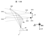
- 13A shows the case where the principal ray of the camera module is incident from the minus side in the depth direction
- FIG. 13B shows the case where the principal ray of the camera module 2 is incident from the plus side in the depth direction.
- the angle of the optical axis OA3 reflected by the plane mirror 30R with respect to the horizontal axis is the angle ⁇ 3, and the distance of the optical axis OA3 from the plane mirror 30R to the pupil of the camera module 2 is d3.
- the angle of the optical axis OA4 reflected by the plane mirror 40R with respect to the horizontal axis is ⁇ 4, and the distance of the optical axis OA4 from the plane mirror 40R to the pupil of the camera module 2 is d4.
- d1(1+sin ⁇ 1) d2(1+sin ⁇ 2).
- the base line length can be changed by arranging the plane mirror 30R and the plane mirror 30L apart from each other. As a result, remote detection can also be realized.
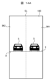
- the sensor 100 may be arranged in the vertical direction as shown in FIG. 14A.
- the angle of view in the vertical direction (vertical direction in the figure) can be widened.
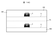
- the stereo camera 10 may be rotated, for example, by 90 degrees with respect to the depth axis.
- images such as those shown in FIGS. 14B and 14C are obtained.
- Parallax in the horizontal direction is detected in the cases of FIGS. 12 and 14A, but parallax in the vertical direction is detected in the cases of FIGS. 14B and 14C.
- FIG. 14B has the advantage of widening the angle of view in the vertical direction.
- FIG. 14C has the advantage that the horizontal angle of view can be widened.
- the two mirrors were flat.
- the mirror may be curved to widen the field of view.
- a wide-angle stereo camera can be realized without using a wide-angle lens.
- the angle between the plane formed by the optical axes OA3 and OA4 inside the stereo camera 10 and the plane formed by the optical axes OA3 and OA4 outside the stereo camera 10 can be reduced.
- the inclination of the two images can be reduced, and the stereoscopic common area CA can be increased.
- a plane mirror has higher distance measurement accuracy than a curved mirror.
- the reason for this is the effect of aberration.
- the ray bundle forming one pixel on the sensor has different inclinations, and thus aberration occurs. This reduces resolution.
- the curved mirror has low robustness against rotational and positional deviations of the mirror. Plane mirrors are almost position independent, while curved mirrors are highly position dependent. Therefore, in consideration of practical use, a highly robust plane mirror is desirable.
- the sizes of the plane mirrors 30R and 30L are not limited.
- the plane mirror 30L closer to the camera module 2 can be made smaller than the plane mirror 30R farther.
- the size of the plane mirror may be asymmetrical. This makes it possible to reduce the size of the stereo camera device.
- FIG. 22 is a diagram showing another configuration example of the optical system of the stereo camera 10. As shown in FIG. This stereo camera 10 does not use a plane mirror on one side.
- two optical axes for realizing a stereo camera are defined as follows. Let OA9 be the optical axis incident on the camera module, and OA10 be the optical axis reflecting the plane mirror 80 .
- FIG. 22 shows the configuration when viewed in a cross section formed by the optical axes OA9 and OA10 outside the stereo camera 10 (viewed from the positive position of the vertical axis).
- dotted lines indicate rays directed toward the camera module 2 .
- the light beams of vertical and horizontal angles of view are reflected by the plane mirror 80, pass through the lens 99 in the camera module 2, and form an image on the sensor 100. , and an image is formed on the sensor 100 .
- a line obtained by extending a light ray incident on the camera module 2 and directed toward the flat mirror 80 is indicated by a dashed line.
- a virtual viewpoint VP10 is defined as a point where the dashed-dotted lines approximately intersect.
- the virtual viewpoints VP9 and VP10 indicate effective positions of the camera module 2.
- FIG. This is the same as detection from the virtual viewpoint VP10 because the light rays are reflected by the plane mirror 80.
- FIG. Therefore, here, the distance and position to the object are detected using the images detected from the two horizontal virtual viewpoints VP9 and VP10.
- a feature of this example is that a single plane mirror 80 is used to achieve stereoscopic vision.
- the optical axis OA9 and the optical axis OA10 are different from the reference axis SA9 and the reference axis SA10 which are perpendicular to the direction of the base length B in the figure. Even in this case, it is possible to measure the distance only by shifting the initial angle of view.
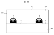
- FIG. 23 shows an image P0 detected by the sensor 100 in the camera module 2.
- FIG. The image P0 is horizontally divided into two by the dividing line SL.
- the image IM1 and the image IM2 are divided substantially equally, but in FIG. 23, the size of the image IM1 and the image IM2 are different.
- the sizes of the images IM1 and IM2 can be matched by enlarging the plane mirror 80, but the size of the stereo camera 10 cannot be reduced. Therefore, in this embodiment, the plane mirror 80 has a predetermined size, and the image IM1 and the image IM2 have different sizes.
- an image IM1 and an image IM2 are generated from the image P0 by the image branching means 60, and the same processing as in FIG. 5 is performed, thereby realizing a stereo camera with only one camera module and a plane mirror.
- the conventional problems of low cost, small size, and environmental resistance can be solved.
- the image branching means 60 in FIG. 5 may extract only the necessary portion of the image IM1 to detect the parallax. By doing so, there is an advantage that the processing in the stereo processing image generation section is reduced.
- the sensors 100 may be arranged in the vertical direction as shown in FIG. 24A.
- the angle of view in the vertical direction (vertical direction in the figure) can be widened.
- the stereo camera may be rotated, for example, by 90 degrees with respect to the depth axis.
- images such as those shown in FIGS. 24B and 24C are obtained.
- Parallax in the horizontal direction is detected in the cases of FIGS. 23 and 24A, but parallax in the vertical direction is detected in the cases of FIGS. 24B and 24C.
- FIG. 24B has the advantage of widening the angle of view in the vertical direction.
- FIG. 24B has the advantage of widening the angle of view in the vertical direction.
- FIG. 24B has the advantage of widening the angle of view in the vertical direction.
- FIGS. 24A and 24B have the advantage of being able to widen the angle in the horizontal direction.
- one side in the horizontal direction can be detected at a wide angle.
- the angle that needs to be detected differs depending on whether the vehicle is turning left or right at an intersection. It is also possible to widen the angle in the corresponding direction.
- the vicinity can be detected.
- a stereo image processing device for processing a stereo image comprising a plurality of reflection units 40R and 40L for reflecting an image of an object, and one camera 99 for photographing an object to be photographed. The image reflected only once by the parts 40R and 40L is detected.” and its application development were explained.
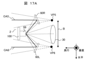
- FIG. 15 is a diagram showing a configuration example of the optical system of the stereo camera 10 according to Example 1 of the present invention.
- the stereo camera 10 of this embodiment is characterized in that the number of mirror reflections is one, as in FIG.
- the two optical axes that realize the stereo camera are defined as follows.
- An optical axis OA5 reflecting the plane mirror 60R and an optical axis OA6 reflecting the plane mirror 60L are assumed.
- the angle formed by the plane formed by the optical axes OA1 and OA2 inside the stereo camera 10 and the plane formed by the optical axes OA1 and OA2 outside the stereo camera 10 is the predetermined angle ⁇ .
- the plane formed by the optical axes OA5 and OA6 inside the stereo camera 10 and the plane formed by the optical axes OA5 and OA6 outside the stereo camera 10 are substantially the same.
- the imaging direction of the stereo camera 10 and the facing direction of the camera module 2 are substantially reversed.
- FIG. 15 shows the configuration when viewed in a cross section formed by the optical axis OA5 and the optical axis OA6 outside the stereo camera 10 (state viewed from the positive position of the vertical axis).
- dotted lines indicate rays directed toward the camera module 2 .
- a line obtained by extending a light ray (dotted line), which is a ray incident on the camera module 2 and directed to the plane mirror 60R and the plane mirror 60L, is indicated by a dashed line.
- a virtual viewpoint VP5 and a virtual viewpoint VP6 are defined as points at which the dashed-dotted lines substantially intersect.
- the virtual viewpoints VP5 and VP6 indicate effective positions of the camera module 2. This is similar to detection from the virtual viewpoints VP5 and VP6, respectively, since the light rays are reflected by the plane mirrors 60R and 60L. Therefore, in this embodiment, the distance and position to the object are detected using the images detected from the two horizontal virtual viewpoints VP5 and VP6.
- the positions and angles of the plane mirrors 60R and 60L are determined so that the camera module 2 itself does not form an image on the sensor.
- the area (range indicated by the dotted line and the dashed line) consisting of a light ray (including the optical axis OA5) incident on the plane mirror 60R and the light ray extending from the light ray (including the optical axis OA5) and the plane mirror
- the pupil position of the lens 99 in the camera module 2 is located between the area (the range indicated by the dotted line and the dashed line) consisting of the light rays (including the optical axis OA6) incident on 60L and the light rays extending from the light rays.
- the plane mirror 60R and the plane mirror 60L are separated from each other and arranged at separate positions.
- the camera 99 can receive rays from three directions. Two of these are from plane mirror 60R and plane mirror 60L, and the remaining one is in the direction in front of camera 99 (the direction of symbol B).
- the front direction of the camera 99 is normally covered by the case of the stereo camera main body, so there is no incoming light from this direction.
- FIG. 16 shows an image P0 detected by the sensor 100 in the camera module 2.
- FIG. The image P0 is horizontally divided into three by the division lines SL1 and SL2 to form three image areas.
- the object 5 is projected on the image areas at both ends where the reflected light from the plane mirrors 60R and 60L is received, but the object is not shown in this state because no light is received in the central image area.
- the image area in FIG. 16 means that there are at least three sensor areas on the sensor of the imaging unit: a first sensor area, a second sensor area, and a third sensor area.
- the image is detected as tilted, but in the configuration of this embodiment, a plane formed by the optical axes OA5 and OA6 inside the stereo camera 10 and the optical axes OA5 and OA6 outside the stereo camera 10 is The images are not tilted because they are almost the same.
- the image branching means 60 generates an image IM1 and an image IM2 from the image areas at both ends of the image P0, and performs the same processing as in FIG.
- a stereo camera can be realized only by As a result, the conventional problems of low cost, small size, and environmental resistance can be solved.
- the plane formed by the optical axes OA5 and OA6 inside the stereo camera 10 and the plane formed by the optical axes OA5 and OA6 outside the stereo camera 10 are made to coincide with each other.
- the angle of view becomes smaller by the amount.
- the camera module is small, the effect will be very small, so the same effect as in FIG. 1 can be obtained.
- the central image area in FIG. 16 is also actively used for image formation.
- the stereo camera 10 as shown in FIGS. 17A and 17B and performing processing such as recognition, pixels can be used effectively.
- a hole 30 is made in the case of the stereo camera main body in the front direction of the camera 99 to take in external light.
- the image IM3 can be detected in the direction opposite to the stereo viewing direction (the plus side in the depth direction) in the images IM1 and IM2.
- the stereo viewing direction the plus side in the depth direction
- FIG. 17A By detecting as shown in FIG. 17A, it is possible to detect not only the front but also the rear. By doing so, for example, it is possible to detect an automobile or a two-wheeled vehicle behind or to the side using the image IM3. Further, by comparing the images IM1 and IM2 (front) with the image IM3 (rear), it is possible to detect the roll, pitch, and yaw direction tilt of the vehicle. In particular, motorcycles tend to tilt in the roll, pitch, and yaw directions with respect to automobiles, so it is necessary to detect these in order to perform accurate warnings and control, and this information can be used to obtain such information. .
- the lens 99 may have different characteristics between the inner peripheral portion and the outer peripheral portion.
- the stereo viewing regions images IM1 and IM2
- the monocular viewing region IM3
- FIG. 17B shows a plane mirror 429 installed in the front direction of the camera 99.
- FIG. Depending on the direction in which the plane mirror 429 faces, it is possible to monitor various directions other than front and back. For example, by using the plane mirror 429 to detect the minus side in the vertical direction in the image IM3, it is possible to detect an object or road surface near the stereo camera 10 . Furthermore, by using the plane mirror 429 and detecting the plus side in the vertical direction in the image IM3, it is also possible to recognize traffic signals and signs.
- the horizontally long sensors are arranged in the horizontal direction, but the sensors 100 may be arranged in the vertical direction as shown in FIG. 18A.
- the stereo camera 10 may be rotated, for example, by 90 degrees with respect to the depth axis.
- images such as those shown in FIGS. 18B and 18C are obtained.
- Parallax in the horizontal direction is detected in the cases of FIGS. 16 and 18A, but parallax in the vertical direction is detected in the cases of FIGS. 18B and 18C.
- FIG. 18B has the advantage of widening the angle of view in the vertical direction.
- FIG. 18C has the advantage that the horizontal angle of view can be widened.
- the camera module 2, the plane mirror 60R, and the plane mirror 60L are formed on the same plane (the plane formed in the depth direction and the horizontal direction), but the camera module 2 is shifted in the vertical direction.
- the same effect can be obtained.
- the configuration is similar to that of FIG.
- equidistant projection is desirable for the imaging lens of the camera module 2 .
- projection in which the image is compressed at the central angle of view and enlarged at the wide-angle side rather than the equidistant projection, it is possible to expand the field of view for stereoscopic viewing of the images IM1 and IM2.
- it is on the wide-angle side such as central projection (ftan ⁇ ) and stereographic projection (2ftan ( ⁇ /2)).
- the stereo image processing apparatus described in the first embodiment includes "a first reflecting unit 60R and a second reflecting unit 60L for reflecting the image of the object 5, and an imaging unit 99 for photographing the object 5, and the imaging unit 99 sensors have at least three sensor areas: a first sensor area IM1, a second sensor area IM2, and a third sensor area IM3.
- the third sensor area IM3 is the first sensor area IM1. It is sandwiched between the second sensor areas IM2, and the light from the target object 5 and reflected by the first reflecting portion 60R enters the first sensor area IM1, and the second sensor area IM1 receives the light. Light from the object 5 and reflected by the second reflecting section 60L is incident on the sensor area IM2.
- FIG. 19 is a diagram showing a configuration example of the optical system of the stereo camera 10 according to Example 2 of the present invention.
- the stereo camera 10 of this embodiment is characterized in that the number of mirror reflections is one, as in FIG.
- the optical axis reflecting the plane mirror 70R is OA7
- the optical axis reflecting the plane mirror 70L is OA8.
- the angle between the plane formed by the optical axis OA1 and the optical axis OA2 inside the stereo camera 10 and the plane formed by the optical axis OA1 and the optical axis OA2 outside the stereo camera 10 is the predetermined angle ⁇ .
- the plane formed by the optical axes OA7 and OA8 inside the stereo camera 10 and the plane formed by the optical axes OA7 and OA8 outside the stereo camera 10 are substantially the same.
- the imaging direction of the stereo camera 10 and the facing direction of the camera module 2 are substantially reversed, but in the stereo camera 10 of the present embodiment, the imaging direction and the facing direction of the camera module 2 are substantially reversed. are substantially the same.
- FIG. 19 shows the configuration when viewed in a cross section formed by the optical axes OA7 and OA8 outside the stereo camera 10 (viewed from the positive position of the vertical axis).
- dotted lines indicate rays directed toward the camera module 2 .
- the points at which the dashed-dotted lines approximately intersect are defined as a virtual viewpoint VP7 and a virtual viewpoint VP8.
- the virtual viewpoints VP7 and VP8 indicate effective positions of the camera module 2.
- FIG. This is the same as that the rays are detected from the virtual viewpoints VP7 and VP8, respectively, because the rays are reflected by the plane mirrors 70R and 70L. Therefore, in this embodiment, the distance and position to the object are detected using the images detected from the two horizontal virtual viewpoints VP7 and VP8.
- This embodiment is characterized in that the wide-angle portion of the camera module 2 is used for stereo viewing.
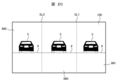
- FIG. 20 shows an image P0 detected by the sensor 100 in the camera module 2.
- FIG. The image P0 is horizontally divided into three by the division lines SL1 and SL2 to form three image areas.
- the object 5 is projected in the image areas at both ends and the central image area that receive the reflected light from the plane mirrors 70R and 70L.
- the image area in FIG. 20 means that there are at least three sensor areas on the sensor of the imaging unit: a first sensor area, a second sensor area, and a third sensor area.
- the image is detected as tilted, but in the configuration of this embodiment, the plane formed by the optical axes OA7 and OA8 inside the stereo camera 10 and the optical axes OA7 and OA8 outside the stereo camera 10 is approximately The image is not skewed because it matches.
- an area (range indicated by a dotted line and a dashed line) consisting of a light ray (including the optical axis OA7) incident on the plane mirror 70R and an extension of the light ray and the plane mirror
- the pupil position of the lens 99 in the camera module 2 is located between the area (the range indicated by the dotted line and the dashed line) consisting of the light beam (including the optical axis OA8) incident on 70L and the extended light beam.
- an image IM1 and an image IM2 are generated from the image P0 by the image branching means 60, and the same processing as in FIG. realizable.
- the conventional problems of low cost, small size, and environmental resistance can be solved.
- the image IM1, image IM2, and image IM3 in this embodiment may have different resolutions.
- the resolution may be different between the peripheral portion and the central portion of the lens 99 .
- By increasing the resolution of the peripheral portion of the lens 99 it is possible to measure the distance of a distant object. Further, it becomes possible to widen the angle by lowering the resolution of the central portion of the lens 99 .
- Conversely, by increasing the resolution of the central portion it becomes possible to detect a distant object even with monocular vision. Further, it becomes possible to widen the angle by lowering the resolution of the peripheral portion of the lens 99 .
- the horizontally long sensors are arranged in the horizontal direction, but the sensors 100 may be arranged in the vertical direction as shown in FIG. 21A.
- the stereo camera 10 may be rotated, for example, by 90 degrees with respect to the depth axis.
- images such as those shown in FIGS. 21B and 21C are obtained.
- Parallax in the horizontal direction is detected in the cases of FIGS. 20 and 21A, but parallax in the vertical direction is detected in the cases of FIGS. 21B and 21C.
- FIG. 21B has the advantage that the angle of view in the vertical direction can be widened.
- FIG. 21C has the advantage of widening the angle of view in the horizontal direction.
- the stereo camera 10 it is possible to detect information in the vertical direction with respect to the stereo camera 10, such as an object near the stereo camera 10, a road surface, a traffic signal, a sign, etc., in the image IM3. can.
- the camera module 2 the plane mirror 70R, and the plane mirror 70L are formed on the same plane (the plane formed in the depth direction and the horizontal direction), but the camera module 2 is shifted in the vertical direction.
- the same effect can be obtained.
- equidistant projection is desirable for the imaging lens of the camera module 2 .
- projection in which the image is compressed at the central angle of view and enlarged at the wide-angle side rather than the equidistant projection, it is possible to expand the field of view for stereoscopic viewing of the images IM1 and IM2.
- it is on the wide-angle side such as central projection (ftan ⁇ ) and stereographic projection (2ftan ( ⁇ /2)).
- the present invention is not limited to the above-described embodiments, and includes various modifications other than those described above.
- the above-described embodiments have been described in detail in order to explain the present invention in an easy-to-understand manner, and are not necessarily limited to those having all the configurations described.
- part of the configuration of one embodiment can be replaced with the configuration of another embodiment, and the configuration of another embodiment can be added to the configuration of one embodiment.
Landscapes
- Engineering & Computer Science (AREA)
- Physics & Mathematics (AREA)
- Multimedia (AREA)
- Signal Processing (AREA)
- Electromagnetism (AREA)
- General Physics & Mathematics (AREA)
- Radar, Positioning & Navigation (AREA)
- Remote Sensing (AREA)
- Measurement Of Optical Distance (AREA)
Priority Applications (3)
| Application Number | Priority Date | Filing Date | Title |
|---|---|---|---|
| DE112022006326.2T DE112022006326T5 (de) | 2022-03-01 | 2022-03-01 | Stereobildverarbeitungsvorrichtung |
| JP2024504033A JP7801421B2 (ja) | 2022-03-01 | 2022-03-01 | ステレオ画像処理装置 |
| PCT/JP2022/008530 WO2023166546A1 (ja) | 2022-03-01 | 2022-03-01 | ステレオ画像処理装置 |
Applications Claiming Priority (1)
| Application Number | Priority Date | Filing Date | Title |
|---|---|---|---|
| PCT/JP2022/008530 WO2023166546A1 (ja) | 2022-03-01 | 2022-03-01 | ステレオ画像処理装置 |
Publications (1)
| Publication Number | Publication Date |
|---|---|
| WO2023166546A1 true WO2023166546A1 (ja) | 2023-09-07 |
Family
ID=87883177
Family Applications (1)
| Application Number | Title | Priority Date | Filing Date |
|---|---|---|---|
| PCT/JP2022/008530 Ceased WO2023166546A1 (ja) | 2022-03-01 | 2022-03-01 | ステレオ画像処理装置 |
Country Status (3)
| Country | Link |
|---|---|
| JP (1) | JP7801421B2 (https=) |
| DE (1) | DE112022006326T5 (https=) |
| WO (1) | WO2023166546A1 (https=) |
Citations (3)
| Publication number | Priority date | Publication date | Assignee | Title |
|---|---|---|---|---|
| JP2001141448A (ja) * | 1999-11-10 | 2001-05-25 | Fuji Photo Film Co Ltd | 光学装置 |
| JP2006078291A (ja) * | 2004-09-08 | 2006-03-23 | Tokyo Institute Of Technology | 全方位三次元計測装置 |
| JP2010118716A (ja) * | 2008-11-11 | 2010-05-27 | Isuzu Motors Ltd | ステレオ撮像装置 |
Family Cites Families (5)
| Publication number | Priority date | Publication date | Assignee | Title |
|---|---|---|---|---|
| JP4265037B2 (ja) | 1998-07-31 | 2009-05-20 | ソニー株式会社 | 三次元撮像装置とステレオカメラ記録再生システム |
| JP5234490B2 (ja) * | 2007-12-14 | 2013-07-10 | サクサ株式会社 | ステレオ画像形成装置 |
| EP2875315B1 (en) | 2012-07-23 | 2018-09-05 | Ricoh Company, Ltd. | Stereo camera |
| JP2015049130A (ja) * | 2013-08-30 | 2015-03-16 | 株式会社ニコン | 反射ユニット |
| JP7756021B2 (ja) * | 2022-03-01 | 2025-10-17 | Astemo株式会社 | ステレオ画像処理装置 |
-
2022
- 2022-03-01 WO PCT/JP2022/008530 patent/WO2023166546A1/ja not_active Ceased
- 2022-03-01 JP JP2024504033A patent/JP7801421B2/ja active Active
- 2022-03-01 DE DE112022006326.2T patent/DE112022006326T5/de active Pending
Patent Citations (3)
| Publication number | Priority date | Publication date | Assignee | Title |
|---|---|---|---|---|
| JP2001141448A (ja) * | 1999-11-10 | 2001-05-25 | Fuji Photo Film Co Ltd | 光学装置 |
| JP2006078291A (ja) * | 2004-09-08 | 2006-03-23 | Tokyo Institute Of Technology | 全方位三次元計測装置 |
| JP2010118716A (ja) * | 2008-11-11 | 2010-05-27 | Isuzu Motors Ltd | ステレオ撮像装置 |
Also Published As
| Publication number | Publication date |
|---|---|
| DE112022006326T5 (de) | 2024-11-28 |
| JP7801421B2 (ja) | 2026-01-16 |
| JPWO2023166546A1 (https=) | 2023-09-07 |
Similar Documents
| Publication | Publication Date | Title |
|---|---|---|
| US10719955B2 (en) | Camera extrinsic parameters estimation from image lines | |
| JP6156724B2 (ja) | ステレオカメラ | |
| JP5273356B2 (ja) | 複眼画像入力装置及びそれを用いた距離測定装置 | |
| EP3667413B1 (en) | Stereo image processing device | |
| US8134608B2 (en) | Imaging apparatus | |
| EP3214474B1 (en) | Optical system, image capturing device and distance measuring system | |
| US20150130942A1 (en) | Image processing device | |
| CN107122770B (zh) | 多目相机系统、智能驾驶系统、汽车、方法和存储介质 | |
| CN115665400B (zh) | 增强现实抬头显示成像方法、装置、设备以及存储介质 | |
| KR20210114949A (ko) | 차량 탑재 카메라 | |
| JP7756021B2 (ja) | ステレオ画像処理装置 | |
| JP7801421B2 (ja) | ステレオ画像処理装置 | |
| JP6983740B2 (ja) | ステレオカメラシステム、及び測距方法 | |
| JP2010118716A (ja) | ステレオ撮像装置 | |
| EP3974771A1 (en) | Stereo camera system and distance measurement method | |
| JP2024125077A (ja) | 測距装置、撮像装置、移動体、測距方法およびプログラム | |
| JP7207889B2 (ja) | 測距装置および車載カメラシステム | |
| WO2011090053A1 (ja) | 障害物検知警報装置 | |
| JP2001318398A (ja) | 車両周辺視認装置 | |
| JP7652739B2 (ja) | 画像処理装置及び画像処理方法 | |
| JP2025034985A (ja) | 画像処理装置及び画像処理方法 | |
| WO2024219280A1 (ja) | 撮像装置及び情報処理方法 | |
| JP3289563B2 (ja) | 測距装置 | |
| WO2024075147A1 (ja) | カメラシステム | |
| JP2024049235A (ja) | 画像処理装置、ステレオカメラ装置及び画像処理方法 |
Legal Events
| Date | Code | Title | Description |
|---|---|---|---|
| 121 | Ep: the epo has been informed by wipo that ep was designated in this application |
Ref document number: 22929695 Country of ref document: EP Kind code of ref document: A1 |
|
| ENP | Entry into the national phase |
Ref document number: 2024504033 Country of ref document: JP Kind code of ref document: A |
|
| WWE | Wipo information: entry into national phase |
Ref document number: 112022006326 Country of ref document: DE |
|
| 122 | Ep: pct application non-entry in european phase |
Ref document number: 22929695 Country of ref document: EP Kind code of ref document: A1 |