WO2023162671A1 - ドリル及び切削加工物の製造方法 - Google Patents
ドリル及び切削加工物の製造方法 Download PDFInfo
- Publication number
- WO2023162671A1 WO2023162671A1 PCT/JP2023/003954 JP2023003954W WO2023162671A1 WO 2023162671 A1 WO2023162671 A1 WO 2023162671A1 JP 2023003954 W JP2023003954 W JP 2023003954W WO 2023162671 A1 WO2023162671 A1 WO 2023162671A1
- Authority
- WO
- WIPO (PCT)
- Prior art keywords
- margin
- region
- drill
- discharge groove
- groove
- Prior art date
- Legal status (The legal status is an assumption and is not a legal conclusion. Google has not performed a legal analysis and makes no representation as to the accuracy of the status listed.)
- Ceased
Links
Images


Classifications
-
- B—PERFORMING OPERATIONS; TRANSPORTING
- B23—MACHINE TOOLS; METAL-WORKING NOT OTHERWISE PROVIDED FOR
- B23B—TURNING; BORING
- B23B51/00—Tools for drilling machines
- B23B51/02—Twist drills
-
- B—PERFORMING OPERATIONS; TRANSPORTING
- B23—MACHINE TOOLS; METAL-WORKING NOT OTHERWISE PROVIDED FOR
- B23B—TURNING; BORING
- B23B2251/00—Details of tools for drilling machines
- B23B2251/44—Margins, i.e. the narrow portion of the land which is not cut away to provide clearance on the circumferential surface
- B23B2251/443—Double margin drills
Definitions
- This aspect relates to a method for manufacturing a drill and a machined product.
- the drills described in Patent Documents 1 and 2 are known as rotary tools used when milling a work material.
- the drill described in Patent Document 1 has three or more margins on the land. In general, by providing a plurality of margins on the outer peripheral surface of the drill, run-out during cutting can be reduced and stable cutting can be performed.
- the outer peripheral surface is formed with a first margin connected to the flank face of the leading edge and a second margin positioned rearward in the rotational direction with respect to the first margin.
- the width of the second margin in the circumferential direction of the rotating shaft decreases toward the rear end of the drill body.
- a drill has a rod-shaped body extending from a first end toward a second end along an axis of rotation.
- the main body includes a first outer peripheral surface extending from a first end toward a second end, a cutting edge located on the first end side, a cutting edge extending from the cutting edge toward the second end side, and a first A first discharge groove that is adjacent to the outer peripheral surface in front of the rotating shaft in the rotating direction, extends from the cutting edge toward the second end, and is adjacent to the first outer peripheral surface in the rotating direction to the rear. and a second discharge groove.
- the first outer peripheral surface has a first margin extending along the first discharge groove, a second margin extending along the second discharge groove, and a first clearance positioned between the first margin and the second margin. ,have.
- the first margin extends closer to the second end than the second margin, and the second margin includes a first region located on the first end side and a and a second region located.
- the width of the second region in the circumferential direction of the rotating shaft decreases from the first end to the second end.
- the second discharge groove has a first portion connected to the first region and a second portion connected to the second region. The width of the second portion in the circumferential direction increases from the first end toward the second end.
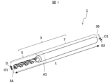
- FIG. 1 is a perspective view showing a rotary tool according to one embodiment
- FIG. 2 is an enlarged view of a region A1 shown in FIG. 1
- FIG. It is a top view which shows the rotating tool which concerns on one Embodiment.
- FIG. 4 is a plan view of the rotary tool shown in FIG. 3 as seen from the B1 direction; 4 is an enlarged view of a region A2 shown in FIG. 3;
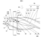
- FIG. FIG. 6 is a plan view of the rotary tool shown in FIG. 5 as viewed from the direction B2;
- FIG. 6 is a cross-sectional view of the VII-VII cross section shown in FIG. 5;
- FIG. 6 is a cross-sectional view of the VIII-VIII cross section shown in FIG. 5;
- FIG. 4 is a plan view of the rotary tool shown in FIG. 3 as seen from the B1 direction
- 4 is an enlarged view of a region A2 shown in FIG. 3
- FIG. 6 is a plan view of
- FIG. 6 is a sectional view of the IX-IX section shown in FIG. 5; It is the schematic which shows 1 process of the manufacturing method of the cut workpiece which concerns on one Embodiment. It is the schematic which shows 1 process of the manufacturing method of the cut workpiece which concerns on one Embodiment. It is the schematic which shows 1 process of the manufacturing method of the cut workpiece which concerns on one Embodiment.
- rotary tool of the embodiment will be described in detail below with reference to the drawings. Specifically, a drill as an example of the rotary tool will be described in detail with reference to the drawings. Examples of rotary tools include end mills and reamers in addition to drills. Accordingly, other rotary tools such as end mills may be substituted for the drills described below.
- the drill may include optional components not shown in the figures to which this specification refers. Also, the dimensions of the members in each drawing do not faithfully represent the dimensions of the actual constituent members and the dimensional ratios of the respective members.
- the drill 1 of the embodiment of the present disclosure has a rod-shaped main body 3 extending along the rotation axis O1 from the first end 3A toward the second end 3B, like the example shown in FIG.
- the rod-shaped main body 3 is rotatable in a rotation direction O2 about a rotation axis O1 during cutting of a work material for manufacturing a machined product.
- the lower left end of the main body 3 is the first end 3A
- the upper right end is the second end 3B
- the first end 3A is also called the leading end
- the second end 3B is also called the trailing end.
- leading end 3A and the trailing end 3B are used.
- the main body 3 has a cutting portion 5 located on the side of the tip 3A and a shank portion 7 located on the side of the rear end 3B of the cutting portion 5 .
- the cutting portion 5 includes a portion that contacts the work material, and this portion plays a major role in cutting the work material.
- the shank portion 7 is a portion that is gripped by a rotating spindle or the like in a machine tool, and may be designed according to the shape of the spindle. Examples of the shape of the shank portion 7 include straight shank, long shank, and long neck.
- the outer peripheral surface 9 is located outside from the front end 3A of the main body 3 to the rear end 3B.
- the cutting edge 13 is located on the tip 3A side of the main body 3 . Since the cutting edge 13 is generally called a tip edge, the cutting edge 13 may also be called a tip edge.
- the discharge groove 15 extends from the cutting edge 13 toward the rear end 3B.
- the outer peripheral surface 9 is the surface region of the cutting portion 5 that is the farthest from the rotation axis O1.
- the outer peripheral surface 9 may have a substantially constant distance from the rotation axis O1. Specifically, the distance from the rotation axis O1 to the outer peripheral surface 9 does not necessarily have to be constant.
- the outer peripheral surface 9 has a margin 27 and a clearance 31 with slightly different distances from the rotation axis O1, and the distance from the rotation axis O1 to the outer peripheral surface 9 is the margin 27 and the clearance 31. It allows for different distances from the axis O1.
- the outer peripheral surface 9 is composed of a plurality of surfaces separated from each other via the discharge grooves 15 .
- the outer peripheral surface 9 has a plurality of surfaces, one of these multiple surfaces is referred to as the first outer peripheral surface 9A.
- the first outer peripheral surface 9A When the first outer peripheral surface 9A is rotated around the rotation axis O1, the first outer peripheral surface 9A may overlap with the outer peripheral surface 9 other than the first outer peripheral surface 9A.
- each outer peripheral surface 9 has 180° rotational symmetry around the rotation axis O1.
- the distal end surface 11 is a surface located on the distal end 3A side of the main body 3 .
- the tip face 11 is positioned behind the cutting edge 13 in the rotational direction O2.
- the tip face 11 is generally called a flank face, and may have a plurality of inclined planes or may have a curved shape.
- the tip surface 11 may have an opening 17 through which coolant is discharged. In this case, the coolant is discharged from the opening 17 through the channel inside the main body 3 .
- the main body 3 has one or more tip surfaces 11 .
- the number of tip surfaces 11 corresponds to the number of cutting edges 13, and in the example shown in FIG. 4, both the number of tip surfaces 11 and cutting edges 13 are two.
- one of the plurality of tip surfaces 11 is defined as a first tip surface 11A.
- the tip surfaces 11 other than the first tip surface 11A may overlap each other.
- each tip surface 11 is rotationally symmetrical about the rotation axis O1 by 180°.
- the cutting edge 13 has a main cutting edge 19 extending from the rotating shaft O1 side toward the outer peripheral surface 9 side, as shown in FIG.
- the end portion of the major cutting edge 19 on the side of the outer peripheral surface 9 is located closer to the rear end 3B than the end portion of the major cutting edge 19 on the side of the rotation axis O1.
- the major cutting edge 19 refers to a portion of the cutting edge 13 that is located on the ridgeline where the tip end face 11 and the discharge groove 15 intersect and has a positive rake angle.
- the cutting edge 13 is a chisel blade 21 including the rotation axis O1 and a chisel blade 21 extending from the chisel blade 21 to the outer peripheral surface 9 of the main body 3. It has a thinning edge 23 extending toward it.
- the discharge groove 15 has a thinning surface 25, and the thinning edge 23 is positioned on the ridgeline where the tip surface 11 and the thinning surface 25 of the cutting edge 13 intersect, and has a negative rake angle. refers to the part that is the value of The thinning edge 23 may be positioned closer to the rotation axis O ⁇ b>1 than the main cutting edge 19 or may be connected to the main cutting edge 19 . That is, in a front view of the main body 3, the chisel edge 21, the thinning edge 23, and the main cutting edge 19 of the cutting edge 13 may be arranged in order from the rotation axis O1 toward the outer circumference.
- the chisel edge 21 refers to a portion of the cutting edge 13 located on the ridgeline where the plurality of tip surfaces 11 intersect each other.
- the chisel blade 21 in the example shown in FIG. 4 intersects the axis of rotation O1.
- the chisel blade 21 may be connected to the thinning blade 23 when viewed from the tip 3A side.
- the discharge groove 15 may extend straight from the cutting edge 13 toward the rear end 3B side, or may extend twisted. In the example shown in FIG. 2, the discharge groove 15 twists around the axis of rotation O1 and extends from the cutting edge 13 toward the rear end 3B.
- twistingly extending means that the discharge groove 15 extends generally twistingly from the cutting edge 13 toward the rear end 3B. In the example shown in FIG. 2, the discharge groove 15 extends spirally. The discharge groove 15 may have a partially untwisted portion.
- the twist angle of the ejection groove 15 is not limited to a specific value, and can be set to, for example, about 10° to 35°.
- first discharge groove 15A one of the plurality of discharge grooves 15 is designated as the first discharge groove 15A and the other as the second discharge groove 15B.
- the first discharge groove 15A and the second discharge groove 15B are each in contact with the first outer peripheral surface 9A.
- the first discharge groove 15A is adjacent to the first outer peripheral surface 9A forward in the rotational direction O2.
- the second discharge groove 15B is adjacent to the first outer peripheral surface 9A rearward in the rotational direction O2.
- the second discharge groove 15B may have the same configuration as the first discharge groove 15A. That is, when the second discharge groove 15B is rotated around the rotation axis O1, the second discharge groove 15B may overlap the first discharge groove 15A. Specifically, in the example shown in FIG. 4 and the like, the first discharge groove 15A and the second discharge groove 15B are rotationally symmetrical about the rotation axis O1 by 180°. Further, the discharge grooves 15 other than the first discharge groove 15A and the second discharge groove 15B among the plurality of discharge grooves 15 may have the same configuration as the first discharge groove 15A and the second discharge groove 15B.
- FIGS. 3 and 5 are plan views seen from a direction orthogonal to the rotation axis O1, and can be called side views.
- the first outer peripheral surface 9A has a plurality of margins 27 extending from the front end 3A side to the rear end 3B side, as shown in FIGS.
- the margin 27 comes into sliding contact with the inner wall surface of the hole to be machined when the cutting edge 13 cuts the work material, and has the function of a guide that stabilizes the advancing direction of the drill 1 .
- the tip portion 29 of each margin 27 is in contact with the first tip surface 11A.
- the front end portion 29 refers to a portion of each margin 27 located on the front end 3A side.
- the first outer peripheral surface 9A has, as one of the plurality of margins 27, a first margin 27A extending along the first discharge groove 15A.
- the first margin 27A is in contact with the first discharge groove 15A, but it is not particularly limited.
- the first margin 27A extends from the main cutting edge 19 toward the rear end 3B. Also, the first margin 27A is in contact with the main cutting edge 19 .
- the first margin 27A is located at the front end in the rotation direction O2 on the first outer peripheral surface 9A.
- the tip portion 29 at the first margin 27A is referred to as a first tip portion 29A.
- the first outer peripheral surface 9A has, as one of the plurality of margins 27, a second margin 27B extending along the second discharge groove 15B.
- the second margin 27B is in contact with the second discharge groove 15B.
- the second margin 27B extends from the first tip surface 11A toward the rear end 3B.
- the second margin 27B is located at the rear end in the rotation direction O2 on the first outer peripheral surface 9A.
- the tip portion 29 at the second margin 27B is referred to as a second tip portion 29B.
- the first outer peripheral surface 9A has clearances 31 as portions other than the plurality of margins 27. As shown in FIG. The first outer peripheral surface 9A has a first clearance 31A located between the first margin 27A and the second margin 27B. When the first outer peripheral surface 9A has margins 27 other than the first margin 27A and the second margin 27B, the first clearance 31A may be configured by a plurality of surface regions.
- the distance from the rotation axis O1 corresponding to the radial thickness of the clearance 31 is slightly shorter than the distance from the rotation axis O1 corresponding to the radial thickness of the margin 27. Since the main body 3 has the clearance 31, the area of contact with the inner wall surface of the machined hole is reduced, and the frictional heat due to the contact can be reduced, thereby improving the durability of the drill. As a result, the drill 1 can reduce the occurrence of scratches on the inner wall surface of the machined hole caused by chipping of the drill 1 .
- the widths of the margins 27 and the clearances 31 excluding the second margin 27B in the circumferential direction of the rotation axis O1 may be constant.
- the first margin 27A may have a larger width in the circumferential direction of the rotation axis O1 than the other margins 27.
- Constant width does not necessarily mean that the width is constant, and it is sufficient that the width as a whole falls within the range of 95% to 105%. This does not necessarily mean that the width is constant even for the description that the width is constant, which will be described later.
- the first margin 27A extends closer to the rear end 3B than the second margin 27B. In the example shown in FIG. 5, the first margin 27A is longer than the second margin 27B in the direction in which the rotation axis O1 extends.
- the second margin 27B has a first region 33 located on the side of the leading end 3A and a second region 35 located on the side of the trailing end 3B relative to the first region 33 .
- the first region 33 may include the second tip 29B, and in the example shown in FIG. 5, the first region 33 is connected to the second region 35.
- the width of the first region 33 in the circumferential direction of the rotation axis O1 may be constant from the front end 3A side toward the rear end 3B side, or may vary slightly.
- FIG. 7 is a cross-sectional view of the main body 3 taken along line VII-VII shown in FIG.
- the VII-VII cross section is a cross section that includes the tip 3A side portion of the second region 35 and is orthogonal to the rotation axis O1.
- FIG. 8 is a cross-sectional view of the main body 3 cut along line VIII-VIII shown in FIG.
- the VIII-VIII cross section is a cross section that includes the center of the second region 35 in the direction in which the rotation axis O1 extends and is perpendicular to the rotation axis O1.
- the width of the second region 35 in the circumferential direction of the rotation axis O1 decreases from the front end 3A side toward the rear end 3B side. Specifically, as in the example shown in FIGS. 7 and 8, the width of the second region 35 near the tip 3A in the circumferential direction is W1, and the width of the portion near the rear end 3B is W1. and the width W2 in the circumferential direction. When these widths W1 and W2 are compared, W1>W2.
- the second region 35 may have a width of 0 in the circumferential direction of the rotation axis O1 on the side of the rear end 3B.
- disappearance of the second region 35 When the second region 35 disappears, it is possible to increase the width of the second discharge groove 15B connected to the second region 35 in the circumferential direction.
- the second discharge groove 15B has a first portion 37 connected to the first region 33 and a second portion 39 connected to the second region 35 .
- the first portion 37 is connected to the second portion 39 .
- the width of the first portion 37 in the circumferential direction of the rotation axis O1 may be constant from the front end 3A toward the rear end 3B.
- the width of the second portion 39 in the circumferential direction of the rotation axis O1 increases from the front end 3A toward the rear end 3B.
- the width in the circumferential direction of the portion of the second portion 39 located on the side of the front end 3A is W3
- the width of the portion located on the side of the rear end 3B from this portion is W3.
- W4 be the width in the circumferential direction at the portion where the When these widths W3 and W4 are compared, W3 ⁇ W4.
- the outer peripheral surface 9 may have one of the margins 27 near the main cutting edge 19 .
- the drill 1 receives the cutting load applied to the main cutting edge 19 during cutting of the workpiece by the contact portion between the margin 27 (first margin 27A) located near the main cutting edge 19 and the inner wall of the machined hole. It is possible to perform stable cutting.
- the outer peripheral surface 9 where the first margin 27A is located has another margin 27 (second margin 27B).
- second margin 27B the distance between the first margin 27A and the second margin 27B is large. It is possible to reduce the influence of the direction in which the force is applied. As a result, it is possible to stabilize the advancing direction of the drill 1 by each slidable contact portion.
- the drill 1 has a plurality of margins 27 on the outer peripheral surface 9 (first outer peripheral surface 9A), and the margin 27 (second margin 27B) located behind the rotation axis O1 extends from the tip 3A.
- the width in the circumferential direction is reduced on the way to the rear end 3B.
- the width of the discharge groove 15 (second discharge groove 15B) in the circumferential direction of the rotating shaft O1 increases.
- the cutting stability of the drill 1 is enhanced by the first margin 27A and the second margin 27B on the tip 3A side.
- the width of the second discharge groove 15B is increased due to the space generated by the reduction in the width of the second margin 27B, resulting in good chip discharge performance. can be secured.
- the drill 1 can perform stable cutting even at the beginning of cutting.
- chips generated by machining are entangled with each other, and chip clogging tends to occur in the discharge groove. Chip discharge performance can be improved by increasing the width of .
- the drill 1 according to the present embodiment can achieve both stability in cutting and good chip discharge performance.
- the first region 33 may be longer than the second region 35 in the direction in which the rotation axis O1 extends. Specifically, the length L1 of the first region 33 may be longer than the length L2 of the second region 35, as in the example shown in FIG. In such a case, the first region 33 becomes relatively long, and the traveling direction of the drill 1 can be guided by a larger area in the second margin 27B. As a result, stable cutting can be performed even at the beginning of cutting when the drill 1 is unstable.
- L1/L2 may be 1.3 or more. In this case, it is possible to further stabilize the cutting at the beginning of cutting. Also, L1/L2 may be 5 or less. In this case, the chip discharge performance at the second portion 39 of the second discharge groove 15B is improved.
- the length of the first region 33 in the direction in which the rotation axis O1 extends may be greater than the radius of the main body 3. Specifically, the length L1 of the first region 33 may be longer than half the outer diameter D of the main body 3 . In such a case, the first region 33 is elongated, and the drill 1 can be guided in the traveling direction with a larger area in the second margin 27B. As a result, stable cutting can be performed even at the beginning of cutting when the drill 1 is unstable.
- the second discharge groove 15B may have a main groove 41 connected to the first region 33, and may have a sub-groove 43 positioned ahead of the main groove 41 in the rotational direction O2.
- the second discharge groove 15B has the main groove 41 and the sub-groove 43 is determined in a cross section including the second region 35 and perpendicular to the rotation axis O1, as shown in FIGS. , and whether or not there is a protrusion 45 in the second discharge groove 15B.
- the thickness of the drill body is ensured at the protrusion 45 rather than forming with an integral groove, so the durability of the drill is improved.
- FIG. 9 is a cross-sectional view of the main body 3 taken along line IX-IX shown in FIG.
- the IX-IX cross section is a cross section that includes the center of the first region 33 in the direction in which the rotation axis O1 extends and is perpendicular to the rotation axis O1.
- the first region 33 may be separated from the sub-groove 43 or connected to the main groove 41 .
- the second region 35 may be separated from the main groove 41 or connected to the sub-groove 43 .
- the sub-groove 43 may be located closer to the rear end 3B than the front end 29 of each margin 27, and extends from the second front end 29B to the front end 3A of the sub-groove 43 in the direction in which the rotation axis O1 extends.
- the interval L3 may be smaller than the length L1 of the first region 33 . In such a case, while the length of the first region 33 is increased, a space for discharging chips can be secured in the portion of the first portion 37 where the sub-grooves 43 are located.
- the sub-groove 43 may be provided from the drill 1 having only the main groove 41 by polishing, laser processing, or the like.
- the width W5 of the main groove 41 may be larger than the width W6 of the minor groove 43 in the circumferential direction of the rotation axis O1. Specifically, W5/W6 may be 1.3 or more.
- the comparison of the widths is based on an imaginary straight line S1 passing through the top of the convex portion 45, which is the boundary between the main groove 41 and the sub-groove 43, and the rotation axis O1, and an imaginary outer circumference circle S2 of the main body 3. is defined as an intersection point P, and the distance from the intersection point P to the open end of each groove is evaluated. Since the main groove 41 contributes to chip disposal at the beginning of cutting, the above configuration can improve the chip discharge performance of the drill 1 even at the beginning of cutting.
- the main groove 41 and the sub-groove 43 are concave in cross section perpendicular to the rotation axis O1. Specifically, it may have a concave curved shape. Also, the depth W7 of the main groove 41 is greater than the depth W8 of the sub-groove 43 . Specifically, W7/W8 may be 1.1 or more.
- the depth of each groove refers to the distance from the deepest part of each groove to the outer circumference circle. Since the main groove 41 contributes to chip disposal at the beginning of cutting, the above configuration increases the depth of the main groove 41 and improves the chip discharge performance of the drill 1 even at the beginning of cutting. can.
- the angle at which the second discharge groove 15B is twisted in the circumferential direction at the first portion 37 and the second portion 39 may be smaller than 180°.
- the front end 3A is located nearer to the imaginary straight line S3 that passes through the position of the second discharge groove 15B when the second discharge groove 15B is twisted by 180° and is perpendicular to the rotation axis O1. It is sufficient if the second margin 27B disappears on the side.
- the second discharge groove 15B on the front end 3A side is larger than the case where the second margin 27B disappears on the rear end 3B side of the imaginary straight line S3. width is increased, and good chip discharge performance can be ensured at the initial stage of cutting.
- the first outer peripheral surface 9A may have a third margin 27C located between the first margin 27A and the second margin 27B.
- the third margin 27C may extend closer to the trailing edge 3B than the second margin 27B.
- the plurality of margins 27 guide the traveling direction of the drill 1, so that more stable cutting can be performed.
- the tip portion 29 at the third margin 27C is referred to as a third tip portion 29C.
- the position of the first tip 29A is positioned closer to the tip 3A than the second tip 29B and the third tip 29C. Since the first tip portion 29A is positioned near the major cutting edge 19, when the first tip portion 29A is positioned closer to the tip 3A than the second tip portion 29B and the third tip portion 29C, At the start of cutting, the cutting edge 13 can come into contact with the work material.
- the position of the second tip portion 29B may be the same as the position of the third tip portion 29C in the direction in which the rotation axis O1 extends.
- the above-mentioned "same position" does not necessarily mean that the second tip portion 29B and the second tip portion 29B and It is not necessary to indicate that the third tip 29C is present.
- the second tip portion 29B and the third tip portion 29C may have a deviation of about ⁇ 2% with respect to the length L of the main body 3 from the direction in which the rotation axis O1 extends.
- the second margin 27B and the third margin 27C are in contact with the work material at the same time during cutting. Therefore, chatter vibration is less likely to occur than when the position of the second tip portion 29B is different from the position of the third tip portion 29C, that is, when each margin 27 comes into contact with the workpiece in stages.
- the configuration of the first margin 27A and the configuration of the second margin 27B may be reversed.
- the width in the circumferential direction of the rotation axis O1 may decrease as the first margin 27A goes from the front end 3A side to the rear end 3B side, and the second margin 27B is closer to the rear end 3B than the first margin 27A. It may extend closer.
- the width of the first discharge groove 15A may be increased corresponding to the reduction in width.
- the positions of the main groove 41 and the sub-groove 43 in the first discharge groove 15A may also be reversed.
- the first discharge groove 15A has a main groove 41 and a sub-groove 43 positioned behind the main groove 41 in the rotational direction O2, and the first margin 27A is a region in contact with the sub-groove 43. may decrease in width in the circumferential direction.
- first margin 27A extends along the first discharge groove 15A and the second margin 27B extends along the second discharge groove 15A.
- the configuration of extending along the groove 15B remains the same.
- Examples of materials for the body 3 include cemented carbide and cermet.
- Compositions of cemented carbide include, for example, WC--Co, WC--TiC--Co and WC--TiC--TaC--Co.
- WC, TiC, TaC are hard particles and Co is the binder phase.
- a cermet is a sintered composite material in which a metal is combined with a ceramic component.
- the cermet includes a titanium compound containing titanium carbide (TiC) or titanium nitride (TiN) as a main component.
- the surface of the body 3 may be coated with a film using a chemical vapor deposition (CVD) method or a physical vapor deposition (PVD) method.
- the composition of the coating includes titanium carbide (TiC), titanium nitride (TiN), titanium carbonitride (TiCN), alumina (Al2O3), and the like.
- a method for manufacturing a cut workpiece in an embodiment of the present disclosure includes: (1) rotating the drill 1 around the rotation axis O1; (2) a step of bringing the cutting edge 13 of the rotating drill 1 into contact with the work material 100; (3) separating the drill 1 from the work material 100;
- the drill 1 is rotated around the rotation axis O1 and moved in the direction (Y1 direction) along the rotation axis O1, thereby moving the drill 1 to the work piece. Relatively close to 100.
- the cutting edge 13 of the drill 1 is brought into contact with the work material 100 to cut the work material 100 .
- the drill 1 is relatively moved away from the work piece 100 by moving the drill 1 in the Y2 direction.
- the drill 1 is brought closer to the work material 100 while the work material 100 is fixed and the drill 1 is rotated around the rotation axis O1.
- the work material 100 is cut by bringing the cutting edge 13 of the rotating drill 1 into contact with the work material 100 .
- the drill 1 is kept away from the work material 100 while being rotated.
- the drill 1 is brought into contact with the work piece 100 by moving the drill 1, or the drill 1 is separated from the work piece 100.
- the drill 1 is brought into contact with the work piece 100 by moving the drill 1, or the drill 1 is separated from the work piece 100.
- the work material 100 may be brought closer to the drill 1. Also, in the step (3), the work material 100 may be kept away from the drill 1 .
- the process of bringing the cutting edge 13 of the drill 1 into contact with different portions of the work piece 100 while keeping the drill 1 rotated may be repeated.
- Representative examples of the material of the work material 100 include aluminum, carbon steel, alloy steel, stainless steel, cast iron, non-ferrous metals, and the like.
Landscapes
- Engineering & Computer Science (AREA)
- Mechanical Engineering (AREA)
- Drilling Tools (AREA)
Priority Applications (3)
| Application Number | Priority Date | Filing Date | Title |
|---|---|---|---|
| DE112023001109.5T DE112023001109T5 (de) | 2022-02-24 | 2023-02-07 | Bohrer und verfahren zur herstellung eines maschinell bearbeiteten produkts |
| CN202380022600.5A CN118715078A (zh) | 2022-02-24 | 2023-02-07 | 钻头以及切削加工物的制造方法 |
| JP2024502987A JPWO2023162671A1 (https=) | 2022-02-24 | 2023-02-07 |
Applications Claiming Priority (2)
| Application Number | Priority Date | Filing Date | Title |
|---|---|---|---|
| JP2022-026894 | 2022-02-24 | ||
| JP2022026894 | 2022-02-24 |
Publications (1)
| Publication Number | Publication Date |
|---|---|
| WO2023162671A1 true WO2023162671A1 (ja) | 2023-08-31 |
Family
ID=87765660
Family Applications (1)
| Application Number | Title | Priority Date | Filing Date |
|---|---|---|---|
| PCT/JP2023/003954 Ceased WO2023162671A1 (ja) | 2022-02-24 | 2023-02-07 | ドリル及び切削加工物の製造方法 |
Country Status (4)
| Country | Link |
|---|---|
| JP (1) | JPWO2023162671A1 (https=) |
| CN (1) | CN118715078A (https=) |
| DE (1) | DE112023001109T5 (https=) |
| WO (1) | WO2023162671A1 (https=) |
Citations (2)
| Publication number | Priority date | Publication date | Assignee | Title |
|---|---|---|---|---|
| JP2006281407A (ja) * | 2005-04-04 | 2006-10-19 | Osg Corp | 非鉄金属加工用ドリル |
| JP4608981B2 (ja) * | 2003-12-17 | 2011-01-12 | 三菱マテリアル株式会社 | ドリル |
Family Cites Families (1)
| Publication number | Priority date | Publication date | Assignee | Title |
|---|---|---|---|---|
| JP2017087406A (ja) * | 2015-11-17 | 2017-05-25 | 三菱日立ツール株式会社 | ドリル |
-
2023
- 2023-02-07 CN CN202380022600.5A patent/CN118715078A/zh active Pending
- 2023-02-07 WO PCT/JP2023/003954 patent/WO2023162671A1/ja not_active Ceased
- 2023-02-07 DE DE112023001109.5T patent/DE112023001109T5/de active Pending
- 2023-02-07 JP JP2024502987A patent/JPWO2023162671A1/ja active Pending
Patent Citations (2)
| Publication number | Priority date | Publication date | Assignee | Title |
|---|---|---|---|---|
| JP4608981B2 (ja) * | 2003-12-17 | 2011-01-12 | 三菱マテリアル株式会社 | ドリル |
| JP2006281407A (ja) * | 2005-04-04 | 2006-10-19 | Osg Corp | 非鉄金属加工用ドリル |
Also Published As
| Publication number | Publication date |
|---|---|
| CN118715078A (zh) | 2024-09-27 |
| JPWO2023162671A1 (https=) | 2023-08-31 |
| DE112023001109T5 (de) | 2024-12-05 |
Similar Documents
| Publication | Publication Date | Title |
|---|---|---|
| JP7216698B2 (ja) | 切削工具及び切削加工物の製造方法 | |
| US11311947B2 (en) | Rotary tool | |
| JP7386339B2 (ja) | ドリル及び切削加工物の製造方法 | |
| JP6941047B2 (ja) | 回転工具及び切削加工物の製造方法 | |
| US10821526B2 (en) | Rotary tool and method for manufacturing machined product | |
| JP7344321B2 (ja) | 回転工具及び切削加工物の製造方法 | |
| JP7279167B2 (ja) | ドリル及び切削加工物の製造方法 | |
| JP7142681B2 (ja) | ドリル及び切削加工物の製造方法 | |
| WO2025204502A1 (ja) | ドリルおよび切削加工物の製造方法 | |
| JP7727830B2 (ja) | ドリル及び切削加工物の製造方法 | |
| US11364556B2 (en) | Rotary tool | |
| WO2023162671A1 (ja) | ドリル及び切削加工物の製造方法 | |
| JPWO2023162671A5 (https=) | ||
| CN115968328A (zh) | 切削刀片、旋转刀具以及切削加工物的制造方法 | |
| CN115666831A (zh) | 钻头 | |
| WO2024224769A1 (ja) | ドリルおよび切削加工物の製造方法 | |
| JP7750804B2 (ja) | ドリル及び切削加工物の製造方法 | |
| JP7391108B2 (ja) | ドリル及び切削加工物の製造方法 | |
| JP7279163B2 (ja) | 回転工具及び切削加工物の製造方法 | |
| JP7558304B2 (ja) | 回転工具及び切削加工物の製造方法 | |
| WO2026088668A1 (ja) | ドリル、及び切削加工物の製造方法 | |
| WO2025182277A1 (ja) | 回転工具、及び切削加工物の製造方法 | |
| WO2024224768A1 (ja) | ドリルおよび切削加工物の製造方法 | |
| JP2025030995A (ja) | 回転工具及び切削加工物の製造方法 | |
| JP5055869B2 (ja) | スローアウェイ式回転工具 |
Legal Events
| Date | Code | Title | Description |
|---|---|---|---|
| 121 | Ep: the epo has been informed by wipo that ep was designated in this application |
Ref document number: 23759675 Country of ref document: EP Kind code of ref document: A1 |
|
| ENP | Entry into the national phase |
Ref document number: 2024502987 Country of ref document: JP Kind code of ref document: A |
|
| WWE | Wipo information: entry into national phase |
Ref document number: 202380022600.5 Country of ref document: CN |
|
| WWE | Wipo information: entry into national phase |
Ref document number: 18840907 Country of ref document: US |
|
| WWE | Wipo information: entry into national phase |
Ref document number: 112023001109 Country of ref document: DE |
|
| 122 | Ep: pct application non-entry in european phase |
Ref document number: 23759675 Country of ref document: EP Kind code of ref document: A1 |