WO2023162178A1 - 溶融金属吐出装置及び溶融金属吐出方法 - Google Patents
溶融金属吐出装置及び溶融金属吐出方法 Download PDFInfo
- Publication number
- WO2023162178A1 WO2023162178A1 PCT/JP2022/008026 JP2022008026W WO2023162178A1 WO 2023162178 A1 WO2023162178 A1 WO 2023162178A1 JP 2022008026 W JP2022008026 W JP 2022008026W WO 2023162178 A1 WO2023162178 A1 WO 2023162178A1
- Authority
- WO
- WIPO (PCT)
- Prior art keywords
- molten metal
- syringe
- opening
- lid
- shaft
- Prior art date
- Legal status (The legal status is an assumption and is not a legal conclusion. Google has not performed a legal analysis and makes no representation as to the accuracy of the status listed.)
- Ceased
Links
Images
Classifications
-
- B—PERFORMING OPERATIONS; TRANSPORTING
- B23—MACHINE TOOLS; METAL-WORKING NOT OTHERWISE PROVIDED FOR
- B23K—SOLDERING OR UNSOLDERING; WELDING; CLADDING OR PLATING BY SOLDERING OR WELDING; CUTTING BY APPLYING HEAT LOCALLY, e.g. FLAME CUTTING; WORKING BY LASER BEAM
- B23K3/00—Tools, devices or special appurtenances for soldering, e.g. brazing, or unsoldering, not specially adapted for particular methods
- B23K3/06—Solder feeding devices; Solder melting pans
- B23K3/0607—Solder feeding devices
-
- C—CHEMISTRY; METALLURGY
- C23—COATING METALLIC MATERIAL; COATING MATERIAL WITH METALLIC MATERIAL; CHEMICAL SURFACE TREATMENT; DIFFUSION TREATMENT OF METALLIC MATERIAL; COATING BY VACUUM EVAPORATION, BY SPUTTERING, BY ION IMPLANTATION OR BY CHEMICAL VAPOUR DEPOSITION, IN GENERAL; INHIBITING CORROSION OF METALLIC MATERIAL OR INCRUSTATION IN GENERAL
- C23C—COATING METALLIC MATERIAL; COATING MATERIAL WITH METALLIC MATERIAL; SURFACE TREATMENT OF METALLIC MATERIAL BY DIFFUSION INTO THE SURFACE, BY CHEMICAL CONVERSION OR SUBSTITUTION; COATING BY VACUUM EVAPORATION, BY SPUTTERING, BY ION IMPLANTATION OR BY CHEMICAL VAPOUR DEPOSITION, IN GENERAL
- C23C4/00—Coating by spraying the coating material in the molten state, e.g. by flame, plasma or electric discharge
- C23C4/12—Coating by spraying the coating material in the molten state, e.g. by flame, plasma or electric discharge characterised by the method of spraying
-
- C—CHEMISTRY; METALLURGY
- C23—COATING METALLIC MATERIAL; COATING MATERIAL WITH METALLIC MATERIAL; CHEMICAL SURFACE TREATMENT; DIFFUSION TREATMENT OF METALLIC MATERIAL; COATING BY VACUUM EVAPORATION, BY SPUTTERING, BY ION IMPLANTATION OR BY CHEMICAL VAPOUR DEPOSITION, IN GENERAL; INHIBITING CORROSION OF METALLIC MATERIAL OR INCRUSTATION IN GENERAL
- C23C—COATING METALLIC MATERIAL; COATING MATERIAL WITH METALLIC MATERIAL; SURFACE TREATMENT OF METALLIC MATERIAL BY DIFFUSION INTO THE SURFACE, BY CHEMICAL CONVERSION OR SUBSTITUTION; COATING BY VACUUM EVAPORATION, BY SPUTTERING, BY ION IMPLANTATION OR BY CHEMICAL VAPOUR DEPOSITION, IN GENERAL
- C23C4/00—Coating by spraying the coating material in the molten state, e.g. by flame, plasma or electric discharge
- C23C4/04—Coating by spraying the coating material in the molten state, e.g. by flame, plasma or electric discharge characterised by the coating material
- C23C4/06—Metallic material
- C23C4/08—Metallic material containing only metal elements
-
- H—ELECTRICITY
- H10—SEMICONDUCTOR DEVICES; ELECTRIC SOLID-STATE DEVICES NOT OTHERWISE PROVIDED FOR
- H10W—GENERIC PACKAGES, INTERCONNECTIONS, CONNECTORS OR OTHER CONSTRUCTIONAL DETAILS OF DEVICES COVERED BY CLASS H10
- H10W72/00—Interconnections or connectors in packages
- H10W72/01—Manufacture or treatment
- H10W72/011—Apparatus therefor
-
- H—ELECTRICITY
- H10—SEMICONDUCTOR DEVICES; ELECTRIC SOLID-STATE DEVICES NOT OTHERWISE PROVIDED FOR
- H10W—GENERIC PACKAGES, INTERCONNECTIONS, CONNECTORS OR OTHER CONSTRUCTIONAL DETAILS OF DEVICES COVERED BY CLASS H10
- H10W72/00—Interconnections or connectors in packages
- H10W72/01—Manufacture or treatment
- H10W72/011—Apparatus therefor
- H10W72/0113—Apparatus for manufacturing die-attach connectors
-
- H—ELECTRICITY
- H10—SEMICONDUCTOR DEVICES; ELECTRIC SOLID-STATE DEVICES NOT OTHERWISE PROVIDED FOR
- H10W—GENERIC PACKAGES, INTERCONNECTIONS, CONNECTORS OR OTHER CONSTRUCTIONAL DETAILS OF DEVICES COVERED BY CLASS H10
- H10W72/00—Interconnections or connectors in packages
- H10W72/01—Manufacture or treatment
- H10W72/013—Manufacture or treatment of die-attach connectors
- H10W72/01321—Manufacture or treatment of die-attach connectors using local deposition
- H10W72/01323—Manufacture or treatment of die-attach connectors using local deposition in liquid form, e.g. by dispensing droplets or by screen printing
Definitions
- the present disclosure relates to a molten metal discharge device and a molten metal discharge method for discharging molten metal.
- a molten metal ejection device is used to apply molten metal to the electrodes of semiconductor elements such as Si chips and SiC chips and bond them to base plates, lead frames, or the like (see, for example, Patent Document 1).
- a typical molten metal dispensing device includes, for example, a glass syringe and shaft. By pulling up the shaft while the tip of the syringe is immersed in the molten metal, a negative pressure is created inside the syringe and the molten metal is sucked. Then, after the tip of the syringe is moved to a predetermined position, the inside of the syringe is pressurized by pushing down the shaft to discharge the molten metal.
- molten metal is used instead of metal wire bonding for connection of main current paths in order to achieve large current, long life, and high reliability. That is, the external electrodes and the semiconductor element are directly bonded by discharging the molten metal to the bonding portion on the semiconductor element. As the area of the joint is reduced, the amount of molten metal required for each joint is also reduced. In other words, it is required to stabilize the discharge amount of the molten metal per one time, that is, the supply amount with higher accuracy.
- the molten metal discharge device discharges molten metal corresponding to the amount of volume fluctuation in the syringe caused by the up-and-down movement of the shaft.
- the ejection amount is difficult to control and the ejection amount per one time is not stable.
- the present disclosure has been made to solve the problems described above, and an object of the present disclosure is to obtain a molten metal dispensing apparatus and a molten metal dispensing method capable of controlling the amount of molten metal to be dispensed with high accuracy. .
- a molten metal discharge apparatus includes a storage portion for storing molten metal, a discharge port for discharging the molten metal stored in the storage portion, an opening different from the discharge port, and the opening.
- a syringe having a bypass passage connected to the storage section and through which the molten metal flows, a heater provided around the syringe to heat the molten metal and maintain the molten state, and a slide inside the syringe. and a lid that is provided at the opening and opens and closes, the opening being above the upper surface of the molten metal inside the syringe. It is characterized by being arranged.
- a bypass path is provided that connects an opening that is different from the discharge port and the housing.
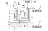
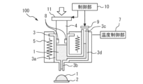
- FIG. 4 is a cross-sectional view showing the molten metal suction operation of the molten metal discharging device according to Embodiment 1; 4 is a cross-sectional view showing the molten metal discharging operation of the molten metal discharging device according to Embodiment 1.
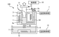
- FIG. FIG. 8 is a cross-sectional view showing the molten metal suction operation of the molten metal discharge device according to Embodiment 2;
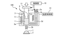
- FIG. 8 is a sectional view showing the molten metal discharging operation of the molten metal discharging device according to Embodiment 2;
- a molten metal discharge device and a molten metal discharge method according to an embodiment will be described with reference to the drawings.
- the same reference numerals are given to the same or corresponding components, and repetition of description may be omitted.
- FIG. 1 is a sectional view showing the molten metal suction operation of the molten metal discharge device according to Embodiment 1.
- FIG. 2 is a sectional view showing the molten metal discharging operation of the molten metal discharging device according to Embodiment 1.
- the molten metal discharge device 100 discharges the molten metal 1 to the joining portion of the parts 2 .
- a component 2 and another member such as a lead frame are joined by the discharged molten metal 1 .
- the molten metal 1 is, for example, a solder material or the like containing Sn or Pb as a main component and an additive element such as Ag or Cu.
- the component 2 may be, for example, an IGBT, a diode, or a reverse-conducting IGBT made of a silicon (Si) material, or made of a material having a larger bandgap than Si, such as silicon carbide (SiC) or gallium nitride (GaN). It may be a MOSFET or a Schottky diode, or simply a metal lead frame made of copper or the like for circuit formation, or a circuit pattern on an insulating substrate. A metal lead frame having a hole may be arranged on the semiconductor element or the like, and the semiconductor element and the metal lead frame may be joined by discharging the molten metal 1 through the hole.
- the molten metal discharge device 100 includes a syringe 3, a shaft 4, a heater 5, and the like.
- the molten metal discharge device 100 is provided with a three-axis movement mechanism of X, Y, and Z orthogonal to each other for reciprocating between the molten metal storage tank 6 and the component 2, but the illustration is omitted. ing.
- the syringe 3 includes a storage portion 3a for storing the molten metal 1, a discharge port 3b for discharging the molten metal 1 stored in the storage portion 3a, an opening 3c different from the discharge port 3b, and the opening 3c and the storage portion. 3a and a bypass passage 3d through which the molten metal 1 flows.
- the opening 3c is located above the upper surface of the molten metal 1 inside the syringe 3.
- the material of the syringe 3 is preferably a material such as glass or ceramic to which the molten metal 1 is not diffusion-bonded, but is not limited to this.
- a heater 5 is provided around the syringe 3 and heats the molten metal 1 in the syringe 3 to keep it in a molten state.
- a temperature control unit 7 controls the heater 5 to keep the molten metal 1 at a temperature equal to or higher than the melting point.
- the heater 5 may heat the molten metal 1 by radiation, induction heating, convective heat transfer, or the like.
- the shaft 4 slides inside the syringe 3 and presses the molten metal 1 stored in the storage portion 3a.
- the shaft 4 has a seal portion 8 for blocking the molten metal 1 in the syringe 3 from the outside air.
- a lid 9 is provided over the opening 3c.
- the control unit 10 controls the driving unit 11 to slide the shaft 4 up and down, and controls other driving units to open and close the lid 9 .
- the control unit 10 can individually control the sliding of the shaft 4 and the opening and closing of the lid 9 .
- the drive unit 11 has mechanisms such as actuators, air cylinders, and single-axis robots.
- the lid 9 When the lid 9 is closed, the bypass route 3d is blocked from the outside air. Outside air can enter and exit the bypass path 3d only when the lid 9 is open.
- the lid 9 may be an air cylinder or an actuator capable of opening/closing control, or an opening/closing valve such as a general gate valve or butterfly valve.
- the bypass route 3 d is one system is illustrated, a plurality of bypass routes 3 d may be provided for one syringe 3 .
- the molten metal 1 in the syringe 3 is sucked from the molten metal storage tank 6.
- a heater 12 is provided around the molten metal storage tank 6 to heat the molten metal 1 in the molten metal storage tank 6 and keep it molten.
- a temperature control unit 13 controls the heater 12 to keep the molten metal 1 at a temperature equal to or higher than the melting point.
- the entire molten metal storage tank 6 is preferably placed in an atmosphere such as an inert gas.
- the discharge port 3b of the syringe 3 is brought into close contact with the liquid surface of the molten metal 1 in the molten metal storage tank 6. Then, the shaft 4 is pulled upward while the cover 9 of the bypass path 3d of the syringe 3 is closed. As a result, the pressure inside the syringe 3 is lowered, and the molten metal 1 is sucked into the syringe 3 (step 1).
- the molten metal discharge device 100 including the syringe 3, the shaft 4, and the temperature control unit 7 is moved by a three-axis moving mechanism (not shown), and the discharge port 3b is placed on the component 2 such as a semiconductor element. (step 2).
- the shaft 4 is pushed down to discharge the molten metal 1 from the discharge port 3b to the part 2 (step 3).
- the cover 9 of the bypass path may be opened during the entire time when the shaft 4 is pushed down, or the cover 9 may be opened only during a part of the time when the shaft 4 is pushed down.
- the discharged molten metal 1 is cooled and solidified (step 4). Thereby, the part 2 and other members can be joined by the molten metal 1 .
- a bypass path 3d is provided that connects the opening 3c, which is different from the discharge port 3b, and the storage portion 3a.
- the discharge amount of the molten metal 1 from the discharge port 3b can also be controlled by discharging the molten metal 1 through the bypass passage 3d to the outside and adjusting the flow rate with a flow control valve.
- the control accuracy of the discharge amount deteriorates due to the heat resistance of the flow control valve and thermal expansion at high temperatures.
- opening 3 c is arranged above the upper surface of molten metal 1 inside syringe 3 . Therefore, since the molten metal 1 passing through the bypass passage 3d is not discharged from the opening 3c, the above problem does not occur.
- the control unit 10 controls the sliding of the shaft 4 and the opening and closing of the lid 9 individually. Therefore, the lid 9 can be opened according to the amount of the molten metal 1 to be discharged, and the molten metal 1 can be allowed to flow through the bypass passage 3d for an arbitrary period of time. For example, instead of opening the lid 9 during the entire molten metal discharge operation, the lid 9 can be opened only during a part of the molten metal discharge operation. Thereby, the discharge amount of the molten metal 1 can be controlled with high precision.
- FIG. 3 is a cross-sectional view showing the molten metal suction operation of the molten metal discharging device according to the second embodiment.
- FIG. 4 is a sectional view showing the molten metal discharging operation of the molten metal discharging device according to the second embodiment.
- a flow control valve 14 is provided at the opening 3c of the bypass path 3d.
- the flow control valve 14 continuously adjusts the flow rate of the air discharged from the inside of the bypass path 3d to the outside.
- the flow control valve 14 is, for example, a diaphragm valve or a butterfly valve. Other configurations are the same as those of the first embodiment.
- the flow control valve 14 is closed when the molten metal 1 is discharged, the air inside the bypass passage 3d is pressurized as the liquid level rises in the bypass passage 3d, and the resistance to the liquid level rise in the bypass passage 3d. Become.
- the flow control valve 14 is opened, the molten metal 1 is discharged from the discharge port 3b and at the same time, a certain amount of the molten metal 1 flows into the bypass passage 3d. Therefore, the pressurized air is released by opening the flow rate control valve 14 while adjusting the flow rate, and the liquid level rising speed of the bypass path 3d is controlled.
- the flow rate of the molten metal 1 flowing through the bypass path 3d can be finely adjusted, so that the discharge amount of the molten metal 1 can be controlled with higher accuracy.
Landscapes
- Chemical & Material Sciences (AREA)
- Engineering & Computer Science (AREA)
- Mechanical Engineering (AREA)
- Physics & Mathematics (AREA)
- Plasma & Fusion (AREA)
- Chemical Kinetics & Catalysis (AREA)
- Materials Engineering (AREA)
- Metallurgy (AREA)
- Organic Chemistry (AREA)
- Coating Apparatus (AREA)
- Electric Connection Of Electric Components To Printed Circuits (AREA)
Abstract
Description
図1は、実施の形態1に係る溶融金属吐出装置の溶融金属吸入動作を示す断面図である。図2は、実施の形態1に係る溶融金属吐出装置の溶融金属吐出動作を示す断面図である。溶融金属吐出装置100は、溶融金属1を部品2の接合部分に吐出する。吐出した溶融金属1により部品2とリードフレーム等の他の部材を接合する。溶融金属1は、例えばSn又はPbなどを主成分としAg又はCuなどの添加元素を含むはんだ材などである。
図3は、実施の形態2に係る溶融金属吐出装置の溶融金属吸入動作を示す断面図である。図4は、実施の形態2に係る溶融金属吐出装置の溶融金属吐出動作を示す断面図である。
Claims (6)
- 溶融金属を収納する収納部と、前記収納部に収納された前記溶融金属を吐出する吐出口と、前記吐出口とは異なる開口部と、前記開口部と前記収納部とを接続し前記溶融金属が流動するバイパス経路とを有するシリンジと、
前記シリンジの周囲に設けられ、前記溶融金属を加熱して溶融状態を保つヒーターと、
前記シリンジの内部を摺動して前記収納部に収納された前記溶融金属を押圧するシャフトと、
前記開口部に設けられ開閉する蓋とを備え、
前記開口部は、前記シリンジの内部にある前記溶融金属の上面より上に配置されていることを特徴とする溶融金属吐出装置。 - 前記シャフトの摺動と前記蓋の開閉を個別に制御することを特徴とする請求項1に記載の溶融金属吐出装置。
- 前記蓋は、前記バイパス経路の内部から外部に排出される空気の流量を調整する流量調整弁であることを特徴とする請求項1又は2に記載の溶融金属吐出装置。
- 前記バイパス経路を通った前記溶融金属が前記開口部から外部に吐出しないことを特徴とする請求項1~3の何れか1項に記載の溶融金属吐出装置。
- 請求項1~4の何れか1項に記載の溶融金属吐出装置を用いた溶融金属吐出方法であって、
前記シリンジの前記吐出口を溶融金属貯留槽内の前記溶融金属の液面に密着させ、前記蓋を閉めた状態で前記シャフトを上方向に引き上げて前記溶融金属を前記シリンジの内部に吸入する工程と、
前記吐出口を部品の上に配置し、前記蓋を開けた状態で前記シャフトを押し下げることで前記吐出口から前記溶融金属を前記部品に吐出する工程とを備えることを特徴とする溶融金属吐出方法。 - 前記シャフトを押し下げる時間の一部の時間のみ前記蓋を開けることを特徴とする請求項5に記載の溶融金属吐出方法。
Priority Applications (5)
| Application Number | Priority Date | Filing Date | Title |
|---|---|---|---|
| US18/703,443 US20250243577A1 (en) | 2022-02-25 | 2022-02-25 | Molten metal discharging device and molten metal discharging method |
| JP2024502406A JP7563648B2 (ja) | 2022-02-25 | 2022-02-25 | 溶融金属吐出装置及び溶融金属吐出方法 |
| CN202280091809.2A CN118695917A (zh) | 2022-02-25 | 2022-02-25 | 熔融金属喷出装置及熔融金属喷出方法 |
| DE112022006726.8T DE112022006726T5 (de) | 2022-02-25 | 2022-02-25 | Ausgabevorrichtung für geschmolzenes Metall und Verfahren zum Ausgabeverfahren für geschmolzenes Metall |
| PCT/JP2022/008026 WO2023162178A1 (ja) | 2022-02-25 | 2022-02-25 | 溶融金属吐出装置及び溶融金属吐出方法 |
Applications Claiming Priority (1)
| Application Number | Priority Date | Filing Date | Title |
|---|---|---|---|
| PCT/JP2022/008026 WO2023162178A1 (ja) | 2022-02-25 | 2022-02-25 | 溶融金属吐出装置及び溶融金属吐出方法 |
Publications (1)
| Publication Number | Publication Date |
|---|---|
| WO2023162178A1 true WO2023162178A1 (ja) | 2023-08-31 |
Family
ID=87765119
Family Applications (1)
| Application Number | Title | Priority Date | Filing Date |
|---|---|---|---|
| PCT/JP2022/008026 Ceased WO2023162178A1 (ja) | 2022-02-25 | 2022-02-25 | 溶融金属吐出装置及び溶融金属吐出方法 |
Country Status (5)
| Country | Link |
|---|---|
| US (1) | US20250243577A1 (ja) |
| JP (1) | JP7563648B2 (ja) |
| CN (1) | CN118695917A (ja) |
| DE (1) | DE112022006726T5 (ja) |
| WO (1) | WO2023162178A1 (ja) |
Citations (3)
| Publication number | Priority date | Publication date | Assignee | Title |
|---|---|---|---|---|
| JPS60255167A (ja) * | 1984-05-31 | 1985-12-16 | Toshiba Chem Corp | 高粘度ワニスの吐出装置 |
| JP2015221452A (ja) * | 2014-05-22 | 2015-12-10 | 三菱電機株式会社 | 溶融金属吐出装置および溶融金属吐出方法 |
| JP2016032803A (ja) * | 2014-03-11 | 2016-03-10 | エンジニアリングシステム株式会社 | 微量流体流出方法および微量流体ディスペンサ |
Family Cites Families (1)
| Publication number | Priority date | Publication date | Assignee | Title |
|---|---|---|---|---|
| JP2014004567A (ja) | 2012-06-27 | 2014-01-16 | Mitsubishi Electric Corp | 溶融金属吐出装置 |
-
2022
- 2022-02-25 WO PCT/JP2022/008026 patent/WO2023162178A1/ja not_active Ceased
- 2022-02-25 JP JP2024502406A patent/JP7563648B2/ja active Active
- 2022-02-25 DE DE112022006726.8T patent/DE112022006726T5/de active Pending
- 2022-02-25 US US18/703,443 patent/US20250243577A1/en active Pending
- 2022-02-25 CN CN202280091809.2A patent/CN118695917A/zh active Pending
Patent Citations (3)
| Publication number | Priority date | Publication date | Assignee | Title |
|---|---|---|---|---|
| JPS60255167A (ja) * | 1984-05-31 | 1985-12-16 | Toshiba Chem Corp | 高粘度ワニスの吐出装置 |
| JP2016032803A (ja) * | 2014-03-11 | 2016-03-10 | エンジニアリングシステム株式会社 | 微量流体流出方法および微量流体ディスペンサ |
| JP2015221452A (ja) * | 2014-05-22 | 2015-12-10 | 三菱電機株式会社 | 溶融金属吐出装置および溶融金属吐出方法 |
Also Published As
| Publication number | Publication date |
|---|---|
| JPWO2023162178A1 (ja) | 2023-08-31 |
| CN118695917A (zh) | 2024-09-24 |
| JP7563648B2 (ja) | 2024-10-08 |
| DE112022006726T5 (de) | 2024-12-19 |
| US20250243577A1 (en) | 2025-07-31 |
Similar Documents
| Publication | Publication Date | Title |
|---|---|---|
| US7793819B2 (en) | Apparatus and method for connecting a component with a substrate | |
| JP5026492B2 (ja) | 加熱されたボンドヘッドを利用した直接ダイボンディング | |
| JP4640170B2 (ja) | 半田付け方法及び半導体モジュールの製造方法並びに半田付け装置 | |
| JP6603401B2 (ja) | ボンディング装置 | |
| JP7455145B2 (ja) | 材料射出のための材料の滴下の防止 | |
| KR101511893B1 (ko) | 와이어 본딩 장치 및 와이어 본딩 방법 | |
| KR20150135050A (ko) | 용융 금속 토출장치 및 용융 금속 토출방법 | |
| US6471110B1 (en) | Method and apparatus for mounting semiconductor chips | |
| WO2023162178A1 (ja) | 溶融金属吐出装置及び溶融金属吐出方法 | |
| KR100923249B1 (ko) | 템플릿의 캐버티들에 용융된 솔더를 주입하는 방법 및 이를수행하기 위한 장치 | |
| KR20020079991A (ko) | 칩 실장 방법 및 장치 | |
| US20140224445A1 (en) | Metal Filling Device | |
| JP2007207899A (ja) | 半田付け装置、半田付け方法、及び半導体装置の製造方法 | |
| KR20110061705A (ko) | 템플릿의 캐버티들에 용융된 솔더를 주입하기 위한 노즐 조립체 및 이를 포함하는 솔더 주입 장치 | |
| WO2018037610A1 (ja) | 変温処理装置および変温処理方法 | |
| WO2007099873A1 (ja) | 電子部品の実装方法及び実装装置、並びに半導体装置の製造方法 | |
| JP2009178639A (ja) | 溶融金属吐出装置 | |
| US20130186945A1 (en) | Manufacturing method for electronic device and electronic device manufacturing apparatus | |
| JP2025107814A (ja) | ボンディング装置 | |
| JP2025094613A (ja) | ボンディング装置 | |
| KR20110002921A (ko) | 템플릿의 캐버티들에 용융된 솔더를 주입하기 위한 장치 | |
| JP2000353773A (ja) | 冷却部品取付方法及びモジュール封止方法 | |
| JP4732894B2 (ja) | ボンディング方法及びボンディング装置 | |
| JP2005175475A (ja) | モジユ−ル封止方法 | |
| KR20100121055A (ko) | 템플릿의 캐버티들에 용융된 솔더를 주입하기 위한 노즐 조립체 및 이를 갖는 장치 |
Legal Events
| Date | Code | Title | Description |
|---|---|---|---|
| 121 | Ep: the epo has been informed by wipo that ep was designated in this application |
Ref document number: 22928705 Country of ref document: EP Kind code of ref document: A1 |
|
| WWE | Wipo information: entry into national phase |
Ref document number: 2024502406 Country of ref document: JP |
|
| WWE | Wipo information: entry into national phase |
Ref document number: 18703443 Country of ref document: US |
|
| WWE | Wipo information: entry into national phase |
Ref document number: 202280091809.2 Country of ref document: CN |
|
| WWE | Wipo information: entry into national phase |
Ref document number: 112022006726 Country of ref document: DE |
|
| 122 | Ep: pct application non-entry in european phase |
Ref document number: 22928705 Country of ref document: EP Kind code of ref document: A1 |
|
| WWP | Wipo information: published in national office |
Ref document number: 18703443 Country of ref document: US |