WO2023162007A1 - 送信装置 - Google Patents
送信装置 Download PDFInfo
- Publication number
- WO2023162007A1 WO2023162007A1 PCT/JP2022/007268 JP2022007268W WO2023162007A1 WO 2023162007 A1 WO2023162007 A1 WO 2023162007A1 JP 2022007268 W JP2022007268 W JP 2022007268W WO 2023162007 A1 WO2023162007 A1 WO 2023162007A1
- Authority
- WO
- WIPO (PCT)
- Prior art keywords
- signal
- frequency
- oam
- oam mode
- mode
- Prior art date
- Legal status (The legal status is an assumption and is not a legal conclusion. Google has not performed a legal analysis and makes no representation as to the accuracy of the status listed.)
- Ceased
Links
Images

Classifications
-
- H—ELECTRICITY
- H04—ELECTRIC COMMUNICATION TECHNIQUE
- H04B—TRANSMISSION
- H04B1/00—Details of transmission systems, not covered by a single one of groups H04B3/00 - H04B13/00; Details of transmission systems not characterised by the medium used for transmission
- H04B1/0003—Software-defined radio [SDR] systems, i.e. systems wherein components typically implemented in hardware, e.g. filters or modulators/demodulators, are implented using software, e.g. by involving an AD or DA conversion stage such that at least part of the signal processing is performed in the digital domain
- H04B1/0007—Software-defined radio [SDR] systems, i.e. systems wherein components typically implemented in hardware, e.g. filters or modulators/demodulators, are implented using software, e.g. by involving an AD or DA conversion stage such that at least part of the signal processing is performed in the digital domain wherein the AD/DA conversion occurs at radiofrequency or intermediate frequency stage
-
- H—ELECTRICITY
- H04—ELECTRIC COMMUNICATION TECHNIQUE
- H04B—TRANSMISSION
- H04B1/00—Details of transmission systems, not covered by a single one of groups H04B3/00 - H04B13/00; Details of transmission systems not characterised by the medium used for transmission
- H04B1/005—Details of transmission systems, not covered by a single one of groups H04B3/00 - H04B13/00; Details of transmission systems not characterised by the medium used for transmission adapting radio receivers, transmitters andtransceivers for operation on two or more bands, i.e. frequency ranges
- H04B1/0096—Details of transmission systems, not covered by a single one of groups H04B3/00 - H04B13/00; Details of transmission systems not characterised by the medium used for transmission adapting radio receivers, transmitters andtransceivers for operation on two or more bands, i.e. frequency ranges where a full band is frequency converted into another full band
-
- H—ELECTRICITY
- H04—ELECTRIC COMMUNICATION TECHNIQUE
- H04B—TRANSMISSION
- H04B7/00—Radio transmission systems, i.e. using radiation field
- H04B7/02—Diversity systems; Multi-antenna system, i.e. transmission or reception using multiple antennas
- H04B7/04—Diversity systems; Multi-antenna system, i.e. transmission or reception using multiple antennas using two or more spaced independent antennas
- H04B7/06—Diversity systems; Multi-antenna system, i.e. transmission or reception using multiple antennas using two or more spaced independent antennas at the transmitting station
- H04B7/0613—Diversity systems; Multi-antenna system, i.e. transmission or reception using multiple antennas using two or more spaced independent antennas at the transmitting station using simultaneous transmission
- H04B7/0615—Diversity systems; Multi-antenna system, i.e. transmission or reception using multiple antennas using two or more spaced independent antennas at the transmitting station using simultaneous transmission of weighted versions of same signal
- H04B7/0617—Diversity systems; Multi-antenna system, i.e. transmission or reception using multiple antennas using two or more spaced independent antennas at the transmitting station using simultaneous transmission of weighted versions of same signal for beam forming
-
- H—ELECTRICITY
- H04—ELECTRIC COMMUNICATION TECHNIQUE
- H04J—MULTIPLEX COMMUNICATION
- H04J99/00—Subject matter not provided for in other groups of this subclass
Definitions
- the present invention relates to technology for spatially multiplexing wireless signals using the orbital angular momentum (OAM) of electromagnetic waves.
- OFAM orbital angular momentum
- Non-Patent Document 1 An electromagnetic wave with OAM has an equiphase plane distributed spirally along the propagation direction centered on the propagation axis. Electromagnetic waves having different OAM modes and propagating in the same direction have orthogonal spatial phase distributions in the rotation axis direction. can be transmitted.
- a plurality of antenna elements are arranged in a circle at equal intervals (hereinafter referred to as UCA (Uniform Circular Array)), and a plurality of OAM modes are generated.
- UCA Uniform Circular Array
- - Spatial multiplex transmission of different signal sequences can be realized by combining and transmitting (for example, Non-Patent Document 2).
- a Butler circuit (Butler matrix circuit), for example, is used for signal generation and signal separation in a plurality of OAM modes.
- Patent Literature 1 discloses a technique for switching between a plurality of OAM modes using discrete Fourier transform.
- Patent Literature 2 discloses a technique of switching the OAM mode by radiation from a pseudo traveling wave resonator using a metamaterial structure by changing the applied magnetic field.
- a transmission device using a UCA and a Butler circuit enables high-capacity communication, but in the future, it is desired to respond to miniaturization, power saving, etc.
- the conventional wireless transmission technology has a problem that it is difficult to realize various OAM modes such as switching between OAM modes and using fractional OAM mode.
- the disclosed technology aims to realize various OAM modes.
- the disclosed technique comprises a first frequency converter configured to convert the frequency of a baseband signal to an intermediate frequency corresponding to a desired OAM mode; and a second frequency converter configured to convert the delayed intermediate frequency signal to a constant radio frequency.
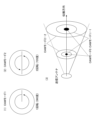
- FIG. 10 is a diagram showing an example of UCA phase setting for generating an OAM mode signal
- FIG. 4 is a diagram showing an example of phase distribution and signal strength distribution of an OAM multiplexed signal
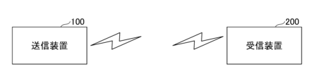
- 1 is a configuration diagram of a communication system according to an embodiment of the present invention
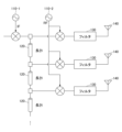
- FIG. It is a figure which shows an example of the hardware constitutions of the transmission apparatus which concerns on embodiment of this invention.
- the transmitting apparatus maintains a constant RF (Radio Frequency) frequency, varies an intermediate frequency (IF), and includes a delay line in each branch.
- RF Radio Frequency
- IF intermediate frequency
- the local oscillation frequency of the first frequency converter from baseband to IF and the local oscillation frequency of the second frequency converter from IF to RF are made variable to change the IF frequency while changing the RF frequency. keep constant.
- the IF frequency By changing the IF frequency, the amount of phase shift in a circuit that generates a fixed time delay is changed according to the desired OAM mode.
- FIG. 1 is a diagram showing an example of UCA phase setting for generating an OAM mode signal.
- the UCA shown in FIG. 1 is a UCA consisting of eight antenna elements.
- the signals of OAM modes 0, 1, 2, 3, are generated by setting the phase of the signal to be supplied to each antenna element so that the phase becomes n rotations (n ⁇ 360 degrees).
- a signal in which the direction of phase rotation is opposite to that of the signal in OAM mode n is called OAM mode-n.
- OAM mode-n A signal in which the direction of phase rotation is opposite to that of the signal in OAM mode n.
- the direction of phase rotation of the signal in the positive OAM mode is assumed to be counterclockwise
- the direction of phase rotation of the signal in the negative OAM mode is assumed to be clockwise.
- signals to be transmitted in each OAM mode may be generated and combined in advance, and the combined signal for each OAM mode may be transmitted using a single UCA, or a plurality of UCAs may be used and different UCAs may be used for each OAM mode. Signals for each OAM mode may be transmitted.
- the phase of each antenna element of the UCA on the receiving side should be set in the opposite direction to the phase of the antenna element on the transmitting side.
- Interference between OAM modes means, for example, that a signal transmitted in OAM mode 1 from a transmitting device is output as a signal in OAM mode 2 on the receiving side.
- FIG. 2 is a diagram showing an example of phase distribution and signal intensity distribution of OAM multiplexed signals.
- the arrows represent the phase distributions of the OAM mode 1 and OAM mode 2 signals viewed from the transmission side on the end face (propagation orthogonal plane) orthogonal to the propagation direction.
- the arrow starts at 0 degrees and the phase changes linearly and the arrow ends at 360 degrees. That is, the signal of OAM mode n propagates while rotating the phase by n (n ⁇ 360 degrees) on the propagation orthogonal plane.
- the arrows of the phase distribution of the signals of OAM modes -1 and -2 are reversed.
- the signal intensity distribution and the position where the signal intensity is maximized differ for each OAM mode.
- the same OAM modes with different signs have the same intensity distribution.
- the higher the order of the OAM mode the farther the position where the signal intensity is maximized from the propagation axis (Non-Patent Document 2).
- the OAM mode with a larger value is called a higher-order mode.
- the OAM mode 3 signal is a higher order mode than the OAM mode 0, OAM mode 1, and OAM mode 2 signals.
- the position where the signal intensity is maximized for each OAM mode is indicated by a circular ring. Accordingly, the beam diameter of the OAM mode multiplexed signal expands, and the ring indicating the position where the signal intensity is maximized for each OAM mode becomes larger.
- FIG. 3 is a configuration diagram of a communication system according to an embodiment of the present invention. As shown in FIG. 3 , the radio communication system according to this embodiment has transmitting apparatus 100 and receiving apparatus 200 .
- the transmitting device 100 and the receiving device 200 each have a UCA.
- transmitting apparatus 100 multiplexes and transmits one or more OAM mode signals
- receiving apparatus 200 receives the multiplexed signal of one or more OAM modes transmitted from transmitting apparatus 100. , separate the signals for each OAM mode.
- the transmitting device 100 and the receiving device 200 are wireless communication devices that perform wireless communication.
- transmitting apparatus 100 is a stationary base station and receiving apparatus 200 is a mobile terminal.
- both transmitting device 100 and receiving device 200 may be stationary base stations, or both transmitting device 100 and receiving device 200 may be mobile terminals.
- each wireless communication device may have the functions of the transmitting device 100 and the receiving device 200, which will be described later.
- FIG. 4 is a diagram showing an example of the hardware configuration of the transmission device according to the embodiment of the present invention.
- the transmitting device 100 comprises a first frequency converter 110-1, a second frequency converter 110-2, one or more delay lines 120, multiple filters 130, and multiple antennas 140.
- FIG. 1 A first frequency converter 110-1, a second frequency converter 110-2, one or more delay lines 120, multiple filters 130, and multiple antennas 140.
- the first frequency converter 110-1 converts the frequency of the baseband signal to an intermediate frequency (IF).
- Delay line 120 introduces a fixed time delay to the intermediate frequency signal.
- the plurality of delay lines 120 may each have a length of l, for example, and may be configured to successively introduce a fixed time delay to the intermediate frequency signal.
- a second frequency converter 110-2 converts the intermediate frequency to a radio frequency (RF) for transmission.
- RF radio frequency
- a plurality of filters 130 and a plurality of antennas 140 constitute a branch without delay and a branch delayed by a fixed time, respectively.
- a plurality of antennas 140 may form, for example, a circular array antenna. This allows transmitting apparatus 100 to assign a specific OAM mode to each filter 130 and antenna 140, respectively.
- the transmitting apparatus 100 controls the first frequency converter 110-1 to change the intermediate frequency (IF), and controls the second frequency converter 110-2 to change the radio frequency (RF) to the intermediate frequency (IF) to be constant regardless of changes in IF).
- IF intermediate frequency
- RF radio frequency
- the transmitting device 100 controls the second frequency converter 110-2 to set the oscillation frequency f2 according to Equation 1, thereby making the radio frequency (RF) constant.
- the transmitting device 100 can continuously switch the OAM mode of the signal to be transmitted. Also, the transmitter 100 can implement various OAM modes such as an integer mode, a fractional mode, and the like.
- the OAM mode can be switched with a simple configuration.
- multiple SPPs Serial Port Profiles
- phase shift circuits etc.
- beam forming circuits etc. are also not required.
- This specification describes at least a transmitter as described in each of the following sections.
- (Section 1) a first frequency converter configured to convert the frequency of the baseband signal to an intermediate frequency corresponding to the desired OAM mode; a delay line configured to delay the intermediate frequency signal; a second frequency converter configured to convert the delayed intermediate frequency signal to a constant radio frequency; transmitter.
- (Section 2) a plurality of said delay lines configured to successively introduce fixed time delays into said intermediate frequency signal; 2.
- the first frequency converter is configured to convert the frequency of the baseband signal to an intermediate frequency corresponding to a fractional OAM mode. 3.
- the transmission device according to claim 1 or 2.
- any of the above configurations provides a technology that enables various OAM modes to be realized.
- a fixed time delay can be generated continuously.
- OAM mode signals in fractional mode can be transmitted.
Landscapes
- Engineering & Computer Science (AREA)
- Computer Networks & Wireless Communication (AREA)
- Signal Processing (AREA)
- Transmitters (AREA)
- Transceivers (AREA)
- Radio Transmission System (AREA)
Abstract
Description
従来、円形アレーアンテナによりOAMモードを活用した無線伝送を行う無線通信装置で、OAMモード変調やOAMモードを切り替えて使用することを目的として、OAMモード可変アレーアンテナを使用する構成が知られている。しかし、OAMモード可変アレーアンテナを使用する場合、各アンテナ素子が備える移相器を制御する必要がある。さらに、多数の移相器を使用すると、移相変動量のばらつきが生じるおそれがある。
本実施の形態に係る送信装置は、RF(Radio Frequency)周波数を一定に保ちつつ中間周波数(IF;Intermediate Frequency)を可変にして、遅延線路を各ブランチに備える。また、ベースバンドからIFへの第一周波数変換器の局部発振周波数と、IFからRFへの第二周波数変換器の局部発振周波数とを可変にして、IF周波数を変更可能にしつつ、RF周波数を一定にする。これによって、使用したいOAMモードに応じて、IF周波数を変更することで固定時間遅延を発生する回路における移相量を変更する。
本実施の形態における各装置において使用されるUCAに係る基本的な設定・動作例について説明する。
図3は、本発明の実施の形態における通信システムの構成図である。図3に示すように、本実施の形態における無線通信システムは、送信装置100と受信装置200を有する。
次に、送信装置のハードウェア構成について説明する。
本明細書には、少なくとも下記の各項に記載した送信装置が記載されている。
(第1項)
ベースバンド信号の周波数を、所望のOAMモードに応じた中間周波数に変換するように構成されている第一周波数変換器と、
前記中間周波数の信号に遅延を発生させるように構成されている遅延線路と、
遅延を発生させた前記中間周波数の信号を、一定の無線周波数に変換するように構成されている第二周波数変換器と、を備える、
送信装置。
(第2項)
前記中間周波数の信号に固定時間の遅延を連続的に発生させるように構成されている複数の前記遅延線路を備える、
第1項に記載の送信装置。
(第3項)
前記第一周波数変換器は、前記ベースバンド信号の周波数を、分数モードのOAMモードに応じた中間周波数に変換するように構成されている、
第1項または第2項に記載の送信装置。
110-1 第一周波数変換器
110-2 第二周波数変換器
120 遅延線路
130 フィルタ
140 アンテナ
200 受信装置
Claims (3)
- ベースバンド信号の周波数を、所望のOAMモードに応じた中間周波数に変換するように構成されている第一周波数変換器と、
前記中間周波数の信号に遅延を発生させるように構成されている遅延線路と、
遅延を発生させた前記中間周波数の信号を、一定の無線周波数に変換するように構成されている第二周波数変換器と、を備える、
送信装置。 - 前記中間周波数の信号に固定時間の遅延を連続的に発生させるように構成されている複数の前記遅延線路を備える、
請求項1に記載の送信装置。 - 前記第一周波数変換器は、前記ベースバンド信号の周波数を、分数モードのOAMモードに応じた中間周波数に変換するように構成されている、
請求項1または2に記載の送信装置。
Priority Applications (3)
| Application Number | Priority Date | Filing Date | Title |
|---|---|---|---|
| US18/835,459 US20250141474A1 (en) | 2022-02-22 | 2022-02-22 | Transmission apparatus |
| JP2024502262A JP7691023B2 (ja) | 2022-02-22 | 2022-02-22 | 送信装置 |
| PCT/JP2022/007268 WO2023162007A1 (ja) | 2022-02-22 | 2022-02-22 | 送信装置 |
Applications Claiming Priority (1)
| Application Number | Priority Date | Filing Date | Title |
|---|---|---|---|
| PCT/JP2022/007268 WO2023162007A1 (ja) | 2022-02-22 | 2022-02-22 | 送信装置 |
Publications (1)
| Publication Number | Publication Date |
|---|---|
| WO2023162007A1 true WO2023162007A1 (ja) | 2023-08-31 |
Family
ID=87765227
Family Applications (1)
| Application Number | Title | Priority Date | Filing Date |
|---|---|---|---|
| PCT/JP2022/007268 Ceased WO2023162007A1 (ja) | 2022-02-22 | 2022-02-22 | 送信装置 |
Country Status (3)
| Country | Link |
|---|---|
| US (1) | US20250141474A1 (ja) |
| JP (1) | JP7691023B2 (ja) |
| WO (1) | WO2023162007A1 (ja) |
Citations (1)
| Publication number | Priority date | Publication date | Assignee | Title |
|---|---|---|---|---|
| JP2017130792A (ja) * | 2016-01-20 | 2017-07-27 | パナソニックIpマネジメント株式会社 | 送信装置、受信装置、および通信方法 |
Family Cites Families (2)
| Publication number | Priority date | Publication date | Assignee | Title |
|---|---|---|---|---|
| WO2015159264A1 (en) * | 2014-04-17 | 2015-10-22 | Rai Radiotelevisione Italiana S.P.A. | System for transmission and/or reception of signals having electromagnetic modes with orbital angular momentum, and device and method thereof |
| CN115117625B (zh) * | 2022-07-05 | 2024-06-14 | 电子科技大学 | 一种在锁相源随机初相条件下产生可相控oam电磁波的方法 |
-
2022
- 2022-02-22 JP JP2024502262A patent/JP7691023B2/ja active Active
- 2022-02-22 WO PCT/JP2022/007268 patent/WO2023162007A1/ja not_active Ceased
- 2022-02-22 US US18/835,459 patent/US20250141474A1/en active Pending
Patent Citations (1)
| Publication number | Priority date | Publication date | Assignee | Title |
|---|---|---|---|---|
| JP2017130792A (ja) * | 2016-01-20 | 2017-07-27 | パナソニックIpマネジメント株式会社 | 送信装置、受信装置、および通信方法 |
Non-Patent Citations (2)
| Title |
|---|
| JIANG XUEFENG, WANG YUANHE, ZHANG CHAO: "Performance Evaluation Based on Joint Frequency and Orbital Angular Momentum Spectrum", 2020 IEEE GLOBECOM WORKSHOPS, IEEE, 1 December 2020 (2020-12-01) - 11 December 2020 (2020-12-11), pages 1 - 6, XP093088023, ISBN: 978-1-7281-7307-8, DOI: 10.1109/GCWkshps50303.2020.9367445 * |
| XU, Z. ET AL.: "6×6 MIMO Equalization Assisted Fractional Orbital Angular Momentum (OAM) Dense Mode-Division Multiplexing (DMDM) for Free- Space Optical Communications", ASIA COMMUNICATIONS AND PHOTONICS CONFERENCE (ACP, 2014, pages 1 - 3, XP033538157 * |
Also Published As
| Publication number | Publication date |
|---|---|
| JPWO2023162007A1 (ja) | 2023-08-31 |
| US20250141474A1 (en) | 2025-05-01 |
| JP7691023B2 (ja) | 2025-06-11 |
Similar Documents
| Publication | Publication Date | Title |
|---|---|---|
| JP7559839B2 (ja) | 送信装置、無線通信システム、及び通信方法 | |
| JP6012873B2 (ja) | 可変電気チルト付きマルチバンド・アンテナ | |
| JP4723575B2 (ja) | データ通信 | |
| US11362440B2 (en) | Antenna device, wireless transmitter, wireless receiver, and wireless communication system | |
| US20170026006A1 (en) | Multi-port amplifier utilizing an adjustable delay function | |
| EP3108586B1 (en) | Reflective-type antenna band and polarization selectable transceiver using a rotatable quarter-wave plate | |
| Sasaki et al. | Pragmatic OAM with polarization multiplexing transmission for future 5G ultra-high capacity radio | |
| WO2017020968A1 (en) | Network node and method for photonic beamforming | |
| JP7691023B2 (ja) | 送信装置 | |
| JP7786547B2 (ja) | 送信装置 | |
| JP7622846B2 (ja) | 送信装置、及び送信方法 | |
| JP7845486B2 (ja) | 送信装置、受信装置、送信制御方法及び受信制御方法 | |
| JP7476985B2 (ja) | 送信装置、及び信号送信方法 | |
| Yarrabothu et al. | Massive mimo and beamforming techniques of 5G networks | |
| JP7563489B2 (ja) | 無線通信システム、送信装置、受信装置、及び通信方法 | |
| JP7626228B2 (ja) | 送受信装置および干渉抑圧方法 | |
| JP7619463B2 (ja) | 無線通信システム、送信装置、及び受信装置 | |
| JP7691022B2 (ja) | 送信装置および送信方法 | |
| JP7544286B2 (ja) | 送信方法及び送信装置 | |
| KR100307875B1 (ko) | 원편파 이동통신 중계 시스템 | |
| JP7414157B2 (ja) | 送信装置、及び信号送信方法 | |
| CN109995395B (zh) | 一种射频收发机 | |
| JP2705325B2 (ja) | ダイバーシチ受信装置 | |
| Chae et al. | A Millimeter-Wave Multi-Functional Single-Channel Beamforming IC | |
| CN118646471A (zh) | 适用于高低轨卫星机载卫星通信天线及信号传输方法 |
Legal Events
| Date | Code | Title | Description |
|---|---|---|---|
| 121 | Ep: the epo has been informed by wipo that ep was designated in this application |
Ref document number: 22928538 Country of ref document: EP Kind code of ref document: A1 |
|
| WWE | Wipo information: entry into national phase |
Ref document number: 18835459 Country of ref document: US |
|
| ENP | Entry into the national phase |
Ref document number: 2024502262 Country of ref document: JP Kind code of ref document: A |
|
| NENP | Non-entry into the national phase |
Ref country code: DE |
|
| 122 | Ep: pct application non-entry in european phase |
Ref document number: 22928538 Country of ref document: EP Kind code of ref document: A1 |
|
| WWP | Wipo information: published in national office |
Ref document number: 18835459 Country of ref document: US |