WO2023157713A1 - Composition de résine, film de blocage de lumière, procédé de production de film de blocage de lumière, substrat sur lequel une paroi de séparation est fixée, et dispositif d'affichage - Google Patents
Composition de résine, film de blocage de lumière, procédé de production de film de blocage de lumière, substrat sur lequel une paroi de séparation est fixée, et dispositif d'affichage Download PDFInfo
- Publication number
- WO2023157713A1 WO2023157713A1 PCT/JP2023/003935 JP2023003935W WO2023157713A1 WO 2023157713 A1 WO2023157713 A1 WO 2023157713A1 JP 2023003935 W JP2023003935 W JP 2023003935W WO 2023157713 A1 WO2023157713 A1 WO 2023157713A1
- Authority
- WO
- WIPO (PCT)
- Prior art keywords
- light
- pigment
- resin composition
- substrate
- partition walls
- Prior art date
Links
- 239000011342 resin composition Substances 0.000 title claims abstract description 194
- 239000000758 substrate Substances 0.000 title claims description 179
- 238000004519 manufacturing process Methods 0.000 title claims description 13
- 238000000638 solvent extraction Methods 0.000 title abstract 2
- 239000000049 pigment Substances 0.000 claims abstract description 142
- 150000001875 compounds Chemical class 0.000 claims abstract description 128
- 239000012463 white pigment Substances 0.000 claims abstract description 74
- 238000010438 heat treatment Methods 0.000 claims abstract description 68
- 239000001055 blue pigment Substances 0.000 claims abstract description 56
- 239000002243 precursor Substances 0.000 claims abstract description 54
- 239000011347 resin Substances 0.000 claims abstract description 43
- 229920005989 resin Polymers 0.000 claims abstract description 43
- 239000003504 photosensitizing agent Substances 0.000 claims abstract description 9
- 238000005192 partition Methods 0.000 claims description 356
- 239000000463 material Substances 0.000 claims description 69
- 210000004027 cell Anatomy 0.000 claims description 61
- 238000000034 method Methods 0.000 claims description 56
- MCMNRKCIXSYSNV-UHFFFAOYSA-N Zirconium dioxide Chemical compound O=[Zr]=O MCMNRKCIXSYSNV-UHFFFAOYSA-N 0.000 claims description 52
- 230000004888 barrier function Effects 0.000 claims description 51
- 239000001057 purple pigment Substances 0.000 claims description 42
- 239000002245 particle Substances 0.000 claims description 41
- NDVLTYZPCACLMA-UHFFFAOYSA-N silver oxide Chemical compound [O-2].[Ag+].[Ag+] NDVLTYZPCACLMA-UHFFFAOYSA-N 0.000 claims description 30
- BQCADISMDOOEFD-UHFFFAOYSA-N Silver Chemical compound [Ag] BQCADISMDOOEFD-UHFFFAOYSA-N 0.000 claims description 26
- 229910052709 silver Inorganic materials 0.000 claims description 26
- 239000004332 silver Substances 0.000 claims description 26
- 229940100890 silver compound Drugs 0.000 claims description 26
- 150000003379 silver compounds Chemical class 0.000 claims description 26
- 229920000728 polyester Polymers 0.000 claims description 24
- 229910019142 PO4 Inorganic materials 0.000 claims description 18
- NBIIXXVUZAFLBC-UHFFFAOYSA-K phosphate Chemical compound [O-]P([O-])([O-])=O NBIIXXVUZAFLBC-UHFFFAOYSA-K 0.000 claims description 18
- 239000010452 phosphate Substances 0.000 claims description 18
- 229910018072 Al 2 O 3 Inorganic materials 0.000 claims description 15
- 229910001923 silver oxide Inorganic materials 0.000 claims description 15
- 239000003638 chemical reducing agent Substances 0.000 claims description 13
- VYPSYNLAJGMNEJ-UHFFFAOYSA-N Silicium dioxide Chemical compound O=[Si]=O VYPSYNLAJGMNEJ-UHFFFAOYSA-N 0.000 claims description 12
- 238000011161 development Methods 0.000 claims description 11
- 229910004298 SiO 2 Inorganic materials 0.000 claims description 9
- 238000001035 drying Methods 0.000 claims description 8
- 239000004973 liquid crystal related substance Substances 0.000 claims description 8
- PNEYBMLMFCGWSK-UHFFFAOYSA-N aluminium oxide Inorganic materials [O-2].[O-2].[O-2].[Al+3].[Al+3] PNEYBMLMFCGWSK-UHFFFAOYSA-N 0.000 claims description 6
- 229910052593 corundum Inorganic materials 0.000 claims description 6
- 229910001845 yogo sapphire Inorganic materials 0.000 claims description 6
- 229910052681 coesite Inorganic materials 0.000 claims description 5
- 229910052906 cristobalite Inorganic materials 0.000 claims description 5
- 239000000377 silicon dioxide Substances 0.000 claims description 5
- 235000012239 silicon dioxide Nutrition 0.000 claims description 5
- 229910052682 stishovite Inorganic materials 0.000 claims description 5
- 229910052905 tridymite Inorganic materials 0.000 claims description 5
- GEIAQOFPUVMAGM-UHFFFAOYSA-N ZrO Inorganic materials [Zr]=O GEIAQOFPUVMAGM-UHFFFAOYSA-N 0.000 claims description 4
- 210000002858 crystal cell Anatomy 0.000 claims description 4
- 230000015572 biosynthetic process Effects 0.000 abstract description 20
- 238000002310 reflectometry Methods 0.000 abstract description 8
- -1 quinonediazide compound Chemical class 0.000 description 107
- 229920001296 polysiloxane Polymers 0.000 description 96
- 239000000243 solution Substances 0.000 description 68
- 239000007787 solid Substances 0.000 description 63
- 239000006185 dispersion Substances 0.000 description 59
- LLHKCFNBLRBOGN-UHFFFAOYSA-N propylene glycol methyl ether acetate Chemical compound COCC(C)OC(C)=O LLHKCFNBLRBOGN-UHFFFAOYSA-N 0.000 description 57
- 239000000203 mixture Substances 0.000 description 48
- 239000002904 solvent Substances 0.000 description 44
- 239000002585 base Substances 0.000 description 32
- 239000011521 glass Substances 0.000 description 31
- 239000010410 layer Substances 0.000 description 31
- GWEVSGVZZGPLCZ-UHFFFAOYSA-N Titan oxide Chemical compound O=[Ti]=O GWEVSGVZZGPLCZ-UHFFFAOYSA-N 0.000 description 30
- 230000000052 comparative effect Effects 0.000 description 30
- 239000011241 protective layer Substances 0.000 description 29
- YXFVVABEGXRONW-UHFFFAOYSA-N Toluene Chemical compound CC1=CC=CC=C1 YXFVVABEGXRONW-UHFFFAOYSA-N 0.000 description 27
- 238000006243 chemical reaction Methods 0.000 description 25
- 239000002270 dispersing agent Substances 0.000 description 23
- 239000011324 bead Substances 0.000 description 21
- 125000004432 carbon atom Chemical group C* 0.000 description 20
- 239000005871 repellent Substances 0.000 description 20
- XLYOFNOQVPJJNP-UHFFFAOYSA-N water Substances O XLYOFNOQVPJJNP-UHFFFAOYSA-N 0.000 description 20
- IJGRMHOSHXDMSA-UHFFFAOYSA-N Atomic nitrogen Chemical compound N#N IJGRMHOSHXDMSA-UHFFFAOYSA-N 0.000 description 16
- NBIIXXVUZAFLBC-UHFFFAOYSA-N Phosphoric acid Chemical compound OP(O)(O)=O NBIIXXVUZAFLBC-UHFFFAOYSA-N 0.000 description 16
- 239000007864 aqueous solution Substances 0.000 description 15
- 238000001723 curing Methods 0.000 description 15
- 230000006870 function Effects 0.000 description 15
- OAICVXFJPJFONN-UHFFFAOYSA-N Phosphorus Chemical compound [P] OAICVXFJPJFONN-UHFFFAOYSA-N 0.000 description 14
- 238000002360 preparation method Methods 0.000 description 14
- KWYUFKZDYYNOTN-UHFFFAOYSA-M Potassium hydroxide Chemical compound [OH-].[K+] KWYUFKZDYYNOTN-UHFFFAOYSA-M 0.000 description 12
- 238000000576 coating method Methods 0.000 description 12
- 229920000058 polyacrylate Polymers 0.000 description 12
- 238000003786 synthesis reaction Methods 0.000 description 12
- 125000000217 alkyl group Chemical group 0.000 description 11
- 239000011248 coating agent Substances 0.000 description 11
- 238000011156 evaluation Methods 0.000 description 11
- 239000007788 liquid Substances 0.000 description 11
- YMWUJEATGCHHMB-UHFFFAOYSA-N Dichloromethane Chemical compound ClCCl YMWUJEATGCHHMB-UHFFFAOYSA-N 0.000 description 10
- QSHDDOUJBYECFT-UHFFFAOYSA-N mercury Chemical compound [Hg] QSHDDOUJBYECFT-UHFFFAOYSA-N 0.000 description 10
- 229910052753 mercury Inorganic materials 0.000 description 10
- 239000011164 primary particle Substances 0.000 description 10
- 238000002834 transmittance Methods 0.000 description 10
- XEEYBQQBJWHFJM-UHFFFAOYSA-N Iron Chemical compound [Fe] XEEYBQQBJWHFJM-UHFFFAOYSA-N 0.000 description 9
- OKKJLVBELUTLKV-UHFFFAOYSA-N Methanol Chemical compound OC OKKJLVBELUTLKV-UHFFFAOYSA-N 0.000 description 9
- MPIAGWXWVAHQBB-UHFFFAOYSA-N [3-prop-2-enoyloxy-2-[[3-prop-2-enoyloxy-2,2-bis(prop-2-enoyloxymethyl)propoxy]methyl]-2-(prop-2-enoyloxymethyl)propyl] prop-2-enoate Chemical compound C=CC(=O)OCC(COC(=O)C=C)(COC(=O)C=C)COCC(COC(=O)C=C)(COC(=O)C=C)COC(=O)C=C MPIAGWXWVAHQBB-UHFFFAOYSA-N 0.000 description 9
- 125000003178 carboxy group Chemical group [H]OC(*)=O 0.000 description 9
- 230000018109 developmental process Effects 0.000 description 9
- 125000000962 organic group Chemical group 0.000 description 9
- 229920000642 polymer Polymers 0.000 description 9
- 239000004094 surface-active agent Substances 0.000 description 9
- 206010034972 Photosensitivity reaction Diseases 0.000 description 8
- 229910000147 aluminium phosphate Inorganic materials 0.000 description 8
- 125000002887 hydroxy group Chemical group [H]O* 0.000 description 8
- 239000003999 initiator Substances 0.000 description 8
- 238000005259 measurement Methods 0.000 description 8
- 229910052757 nitrogen Inorganic materials 0.000 description 8
- 150000002902 organometallic compounds Chemical class 0.000 description 8
- 230000036211 photosensitivity Effects 0.000 description 8
- BASFCYQUMIYNBI-UHFFFAOYSA-N platinum Chemical compound [Pt] BASFCYQUMIYNBI-UHFFFAOYSA-N 0.000 description 8
- 235000013824 polyphenols Nutrition 0.000 description 8
- 150000003254 radicals Chemical class 0.000 description 8
- 238000004528 spin coating Methods 0.000 description 8
- 239000000126 substance Substances 0.000 description 8
- 239000004408 titanium dioxide Substances 0.000 description 8
- BGNXCDMCOKJUMV-UHFFFAOYSA-N Tert-Butylhydroquinone Chemical compound CC(C)(C)C1=CC(O)=CC=C1O BGNXCDMCOKJUMV-UHFFFAOYSA-N 0.000 description 7
- 125000003118 aryl group Chemical group 0.000 description 7
- 125000004435 hydrogen atom Chemical group [H]* 0.000 description 7
- 229910052751 metal Inorganic materials 0.000 description 7
- 239000002184 metal Substances 0.000 description 7
- ISWSIDIOOBJBQZ-UHFFFAOYSA-N phenol group Chemical group C1(=CC=CC=C1)O ISWSIDIOOBJBQZ-UHFFFAOYSA-N 0.000 description 7
- 238000006116 polymerization reaction Methods 0.000 description 7
- 230000008569 process Effects 0.000 description 7
- 239000002096 quantum dot Substances 0.000 description 7
- XCZKKZXWDBOGPA-UHFFFAOYSA-N 2-phenylbenzene-1,4-diol Chemical compound OC1=CC=C(O)C(C=2C=CC=CC=2)=C1 XCZKKZXWDBOGPA-UHFFFAOYSA-N 0.000 description 6
- CSNNHWWHGAXBCP-UHFFFAOYSA-L Magnesium sulfate Chemical compound [Mg+2].[O-][S+2]([O-])([O-])[O-] CSNNHWWHGAXBCP-UHFFFAOYSA-L 0.000 description 6
- DNIAPMSPPWPWGF-UHFFFAOYSA-N Propylene glycol Chemical compound CC(O)CO DNIAPMSPPWPWGF-UHFFFAOYSA-N 0.000 description 6
- XLOMVQKBTHCTTD-UHFFFAOYSA-N Zinc monoxide Chemical class [Zn]=O XLOMVQKBTHCTTD-UHFFFAOYSA-N 0.000 description 6
- 239000003513 alkali Substances 0.000 description 6
- 229910052782 aluminium Inorganic materials 0.000 description 6
- 235000010354 butylated hydroxytoluene Nutrition 0.000 description 6
- 239000003795 chemical substances by application Substances 0.000 description 6
- SWXVUIWOUIDPGS-UHFFFAOYSA-N diacetone alcohol Chemical compound CC(=O)CC(C)(C)O SWXVUIWOUIDPGS-UHFFFAOYSA-N 0.000 description 6
- ZUOUZKKEUPVFJK-UHFFFAOYSA-N diphenyl Chemical compound C1=CC=CC=C1C1=CC=CC=C1 ZUOUZKKEUPVFJK-UHFFFAOYSA-N 0.000 description 6
- 239000003921 oil Substances 0.000 description 6
- 239000012044 organic layer Substances 0.000 description 6
- 238000000059 patterning Methods 0.000 description 6
- 150000002989 phenols Chemical class 0.000 description 6
- 239000000843 powder Substances 0.000 description 6
- 239000000047 product Substances 0.000 description 6
- 238000003756 stirring Methods 0.000 description 6
- 238000003860 storage Methods 0.000 description 6
- WGTYBPLFGIVFAS-UHFFFAOYSA-M tetramethylammonium hydroxide Chemical compound [OH-].C[N+](C)(C)C WGTYBPLFGIVFAS-UHFFFAOYSA-M 0.000 description 6
- 238000010521 absorption reaction Methods 0.000 description 5
- 239000002253 acid Substances 0.000 description 5
- XAGFODPZIPBFFR-UHFFFAOYSA-N aluminium Chemical compound [Al] XAGFODPZIPBFFR-UHFFFAOYSA-N 0.000 description 5
- 230000008859 change Effects 0.000 description 5
- AHUXYBVKTIBBJW-UHFFFAOYSA-N dimethoxy(diphenyl)silane Chemical compound C=1C=CC=CC=1[Si](OC)(OC)C1=CC=CC=C1 AHUXYBVKTIBBJW-UHFFFAOYSA-N 0.000 description 5
- 238000000605 extraction Methods 0.000 description 5
- 229910052739 hydrogen Inorganic materials 0.000 description 5
- 239000001257 hydrogen Substances 0.000 description 5
- 125000001449 isopropyl group Chemical group [H]C([H])([H])C([H])(*)C([H])([H])[H] 0.000 description 5
- BFXIKLCIZHOAAZ-UHFFFAOYSA-N methyltrimethoxysilane Chemical compound CO[Si](C)(OC)OC BFXIKLCIZHOAAZ-UHFFFAOYSA-N 0.000 description 5
- 239000012299 nitrogen atmosphere Substances 0.000 description 5
- NFHFRUOZVGFOOS-UHFFFAOYSA-N palladium;triphenylphosphane Chemical compound [Pd].C1=CC=CC=C1P(C=1C=CC=CC=1)C1=CC=CC=C1.C1=CC=CC=C1P(C=1C=CC=CC=1)C1=CC=CC=C1.C1=CC=CC=C1P(C=1C=CC=CC=1)C1=CC=CC=C1.C1=CC=CC=C1P(C=1C=CC=CC=1)C1=CC=CC=C1 NFHFRUOZVGFOOS-UHFFFAOYSA-N 0.000 description 5
- 229920001721 polyimide Polymers 0.000 description 5
- 238000012545 processing Methods 0.000 description 5
- 230000001603 reducing effect Effects 0.000 description 5
- OVTCUIZCVUGJHS-VQHVLOKHSA-N trans-dipyrrin Chemical class C=1C=CNC=1/C=C1\C=CC=N1 OVTCUIZCVUGJHS-VQHVLOKHSA-N 0.000 description 5
- DBUFXGVMAMMWSD-UHFFFAOYSA-N trimethoxy-[3-(7-oxabicyclo[4.1.0]heptan-4-yl)propyl]silane Chemical compound C1C(CCC[Si](OC)(OC)OC)CCC2OC21 DBUFXGVMAMMWSD-UHFFFAOYSA-N 0.000 description 5
- 238000005160 1H NMR spectroscopy Methods 0.000 description 4
- BXJGUBZTZWCMEX-UHFFFAOYSA-N 2,3-dimethylbenzene-1,4-diol Chemical compound CC1=C(C)C(O)=CC=C1O BXJGUBZTZWCMEX-UHFFFAOYSA-N 0.000 description 4
- SGWZVZZVXOJRAQ-UHFFFAOYSA-N 2,6-Dimethyl-1,4-benzenediol Chemical compound CC1=CC(O)=CC(C)=C1O SGWZVZZVXOJRAQ-UHFFFAOYSA-N 0.000 description 4
- WGCNASOHLSPBMP-UHFFFAOYSA-N Glycolaldehyde Chemical compound OCC=O WGCNASOHLSPBMP-UHFFFAOYSA-N 0.000 description 4
- JGFZNNIVVJXRND-UHFFFAOYSA-N N,N-Diisopropylethylamine (DIPEA) Chemical compound CCN(C(C)C)C(C)C JGFZNNIVVJXRND-UHFFFAOYSA-N 0.000 description 4
- 238000005481 NMR spectroscopy Methods 0.000 description 4
- KDLHZDBZIXYQEI-UHFFFAOYSA-N Palladium Chemical compound [Pd] KDLHZDBZIXYQEI-UHFFFAOYSA-N 0.000 description 4
- 239000004642 Polyimide Substances 0.000 description 4
- 239000004793 Polystyrene Substances 0.000 description 4
- FOIXSVOLVBLSDH-UHFFFAOYSA-N Silver ion Chemical compound [Ag+] FOIXSVOLVBLSDH-UHFFFAOYSA-N 0.000 description 4
- WYURNTSHIVDZCO-UHFFFAOYSA-N Tetrahydrofuran Chemical compound C1CCOC1 WYURNTSHIVDZCO-UHFFFAOYSA-N 0.000 description 4
- SEEVRZDUPHZSOX-WPWMEQJKSA-N [(e)-1-[9-ethyl-6-(2-methylbenzoyl)carbazol-3-yl]ethylideneamino] acetate Chemical compound C=1C=C2N(CC)C3=CC=C(C(\C)=N\OC(C)=O)C=C3C2=CC=1C(=O)C1=CC=CC=C1C SEEVRZDUPHZSOX-WPWMEQJKSA-N 0.000 description 4
- NIXOWILDQLNWCW-UHFFFAOYSA-N acrylic acid group Chemical group C(C=C)(=O)O NIXOWILDQLNWCW-UHFFFAOYSA-N 0.000 description 4
- 150000008064 anhydrides Chemical class 0.000 description 4
- 230000000903 blocking effect Effects 0.000 description 4
- 238000009835 boiling Methods 0.000 description 4
- 239000003086 colorant Substances 0.000 description 4
- 238000000354 decomposition reaction Methods 0.000 description 4
- 125000001495 ethyl group Chemical group [H]C([H])([H])C([H])([H])* 0.000 description 4
- 230000005284 excitation Effects 0.000 description 4
- 238000005227 gel permeation chromatography Methods 0.000 description 4
- 239000003112 inhibitor Substances 0.000 description 4
- 229910052742 iron Inorganic materials 0.000 description 4
- 239000003960 organic solvent Substances 0.000 description 4
- 150000002941 palladium compounds Chemical class 0.000 description 4
- 229910052697 platinum Inorganic materials 0.000 description 4
- 229920002223 polystyrene Polymers 0.000 description 4
- 239000002994 raw material Substances 0.000 description 4
- 230000007261 regionalization Effects 0.000 description 4
- SQGYOTSLMSWVJD-UHFFFAOYSA-N silver(1+) nitrate Chemical compound [Ag+].[O-]N(=O)=O SQGYOTSLMSWVJD-UHFFFAOYSA-N 0.000 description 4
- 239000002002 slurry Substances 0.000 description 4
- 239000001052 yellow pigment Substances 0.000 description 4
- QYGBYAQGBVHMDD-XQRVVYSFSA-N (z)-2-cyano-3-thiophen-2-ylprop-2-enoic acid Chemical compound OC(=O)C(\C#N)=C/C1=CC=CS1 QYGBYAQGBVHMDD-XQRVVYSFSA-N 0.000 description 3
- QIGBRXMKCJKVMJ-UHFFFAOYSA-N 1,4-Benzenediol Natural products OC1=CC=C(O)C=C1 QIGBRXMKCJKVMJ-UHFFFAOYSA-N 0.000 description 3
- ZWEHNKRNPOVVGH-UHFFFAOYSA-N 2-Butanone Chemical compound CCC(C)=O ZWEHNKRNPOVVGH-UHFFFAOYSA-N 0.000 description 3
- 125000003229 2-methylhexyl group Chemical group [H]C([H])([H])C([H])([H])C([H])([H])C([H])([H])C([H])(C([H])([H])[H])C([H])([H])* 0.000 description 3
- ZADOWCXTUZWAKL-UHFFFAOYSA-N 3-(3-trimethoxysilylpropyl)oxolane-2,5-dione Chemical compound CO[Si](OC)(OC)CCCC1CC(=O)OC1=O ZADOWCXTUZWAKL-UHFFFAOYSA-N 0.000 description 3
- CSCPPACGZOOCGX-UHFFFAOYSA-N Acetone Chemical compound CC(C)=O CSCPPACGZOOCGX-UHFFFAOYSA-N 0.000 description 3
- LSNNMFCWUKXFEE-UHFFFAOYSA-M Bisulfite Chemical compound OS([O-])=O LSNNMFCWUKXFEE-UHFFFAOYSA-M 0.000 description 3
- 239000005749 Copper compound Substances 0.000 description 3
- 239000004593 Epoxy Substances 0.000 description 3
- LFQSCWFLJHTTHZ-UHFFFAOYSA-N Ethanol Chemical compound CCO LFQSCWFLJHTTHZ-UHFFFAOYSA-N 0.000 description 3
- XEKOWRVHYACXOJ-UHFFFAOYSA-N Ethyl acetate Chemical compound CCOC(C)=O XEKOWRVHYACXOJ-UHFFFAOYSA-N 0.000 description 3
- LYCAIKOWRPUZTN-UHFFFAOYSA-N Ethylene glycol Chemical compound OCCO LYCAIKOWRPUZTN-UHFFFAOYSA-N 0.000 description 3
- UFHFLCQGNIYNRP-UHFFFAOYSA-N Hydrogen Chemical compound [H][H] UFHFLCQGNIYNRP-UHFFFAOYSA-N 0.000 description 3
- ZMXDDKWLCZADIW-UHFFFAOYSA-N N,N-Dimethylformamide Chemical compound CN(C)C=O ZMXDDKWLCZADIW-UHFFFAOYSA-N 0.000 description 3
- 229910052581 Si3N4 Inorganic materials 0.000 description 3
- HEMHJVSKTPXQMS-UHFFFAOYSA-M Sodium hydroxide Chemical compound [OH-].[Na+] HEMHJVSKTPXQMS-UHFFFAOYSA-M 0.000 description 3
- BOTDANWDWHJENH-UHFFFAOYSA-N Tetraethyl orthosilicate Chemical compound CCO[Si](OCC)(OCC)OCC BOTDANWDWHJENH-UHFFFAOYSA-N 0.000 description 3
- 125000002723 alicyclic group Chemical group 0.000 description 3
- QVGXLLKOCUKJST-UHFFFAOYSA-N atomic oxygen Chemical compound [O] QVGXLLKOCUKJST-UHFFFAOYSA-N 0.000 description 3
- JFDZBHWFFUWGJE-UHFFFAOYSA-N benzonitrile Chemical compound N#CC1=CC=CC=C1 JFDZBHWFFUWGJE-UHFFFAOYSA-N 0.000 description 3
- 125000001797 benzyl group Chemical group [H]C1=C([H])C([H])=C(C([H])=C1[H])C([H])([H])* 0.000 description 3
- 235000010290 biphenyl Nutrition 0.000 description 3
- 239000004305 biphenyl Substances 0.000 description 3
- 239000006227 byproduct Substances 0.000 description 3
- 239000006229 carbon black Substances 0.000 description 3
- 238000001816 cooling Methods 0.000 description 3
- 150000001880 copper compounds Chemical class 0.000 description 3
- 125000002704 decyl group Chemical group [H]C([H])([H])C([H])([H])C([H])([H])C([H])([H])C([H])([H])C([H])([H])C([H])([H])C([H])([H])C([H])([H])C([H])([H])* 0.000 description 3
- JJQZDUKDJDQPMQ-UHFFFAOYSA-N dimethoxy(dimethyl)silane Chemical compound CO[Si](C)(C)OC JJQZDUKDJDQPMQ-UHFFFAOYSA-N 0.000 description 3
- 125000003438 dodecyl group Chemical group [H]C([H])([H])C([H])([H])C([H])([H])C([H])([H])C([H])([H])C([H])([H])C([H])([H])C([H])([H])C([H])([H])C([H])([H])C([H])([H])C([H])([H])* 0.000 description 3
- 238000005516 engineering process Methods 0.000 description 3
- 239000007789 gas Substances 0.000 description 3
- PCHJSUWPFVWCPO-UHFFFAOYSA-N gold Chemical compound [Au] PCHJSUWPFVWCPO-UHFFFAOYSA-N 0.000 description 3
- 229910052737 gold Inorganic materials 0.000 description 3
- 239000010931 gold Substances 0.000 description 3
- 239000001023 inorganic pigment Substances 0.000 description 3
- 125000000959 isobutyl group Chemical group [H]C([H])([H])C([H])(C([H])([H])[H])C([H])([H])* 0.000 description 3
- 125000004491 isohexyl group Chemical group C(CCC(C)C)* 0.000 description 3
- 125000001972 isopentyl group Chemical group [H]C([H])([H])C([H])(C([H])([H])[H])C([H])([H])C([H])([H])* 0.000 description 3
- 229910052943 magnesium sulfate Inorganic materials 0.000 description 3
- 235000019341 magnesium sulphate Nutrition 0.000 description 3
- 125000002960 margaryl group Chemical group [H]C([*])([H])C([H])([H])C([H])([H])C([H])([H])C([H])([H])C([H])([H])C([H])([H])C([H])([H])C([H])([H])C([H])([H])C([H])([H])C([H])([H])C([H])([H])C([H])([H])C([H])([H])C([H])([H])C([H])([H])[H] 0.000 description 3
- 125000002496 methyl group Chemical group [H]C([H])([H])* 0.000 description 3
- 239000011259 mixed solution Substances 0.000 description 3
- 239000000178 monomer Substances 0.000 description 3
- 125000001421 myristyl group Chemical group [H]C([*])([H])C([H])([H])C([H])([H])C([H])([H])C([H])([H])C([H])([H])C([H])([H])C([H])([H])C([H])([H])C([H])([H])C([H])([H])C([H])([H])C([H])([H])C([H])([H])[H] 0.000 description 3
- VLKZOEOYAKHREP-UHFFFAOYSA-N n-Hexane Chemical compound CCCCCC VLKZOEOYAKHREP-UHFFFAOYSA-N 0.000 description 3
- 125000004108 n-butyl group Chemical group [H]C([H])([H])C([H])([H])C([H])([H])C([H])([H])* 0.000 description 3
- 125000003136 n-heptyl group Chemical group [H]C([H])([H])C([H])([H])C([H])([H])C([H])([H])C([H])([H])C([H])([H])C([H])([H])* 0.000 description 3
- 125000001280 n-hexyl group Chemical group C(CCCCC)* 0.000 description 3
- 125000000740 n-pentyl group Chemical group [H]C([H])([H])C([H])([H])C([H])([H])C([H])([H])C([H])([H])* 0.000 description 3
- 125000004123 n-propyl group Chemical group [H]C([H])([H])C([H])([H])C([H])([H])* 0.000 description 3
- 125000001196 nonadecyl group Chemical group [H]C([*])([H])C([H])([H])C([H])([H])C([H])([H])C([H])([H])C([H])([H])C([H])([H])C([H])([H])C([H])([H])C([H])([H])C([H])([H])C([H])([H])C([H])([H])C([H])([H])C([H])([H])C([H])([H])C([H])([H])C([H])([H])C([H])([H])[H] 0.000 description 3
- 230000003287 optical effect Effects 0.000 description 3
- 239000012860 organic pigment Substances 0.000 description 3
- 229920000620 organic polymer Polymers 0.000 description 3
- 150000001282 organosilanes Chemical class 0.000 description 3
- 150000002923 oximes Chemical class 0.000 description 3
- HBEQXAKJSGXAIQ-UHFFFAOYSA-N oxopalladium Chemical compound [Pd]=O HBEQXAKJSGXAIQ-UHFFFAOYSA-N 0.000 description 3
- 229910052760 oxygen Inorganic materials 0.000 description 3
- 239000001301 oxygen Substances 0.000 description 3
- 229910003445 palladium oxide Inorganic materials 0.000 description 3
- 125000000913 palmityl group Chemical group [H]C([*])([H])C([H])([H])C([H])([H])C([H])([H])C([H])([H])C([H])([H])C([H])([H])C([H])([H])C([H])([H])C([H])([H])C([H])([H])C([H])([H])C([H])([H])C([H])([H])C([H])([H])C([H])([H])[H] 0.000 description 3
- 125000002958 pentadecyl group Chemical group [H]C([*])([H])C([H])([H])C([H])([H])C([H])([H])C([H])([H])C([H])([H])C([H])([H])C([H])([H])C([H])([H])C([H])([H])C([H])([H])C([H])([H])C([H])([H])C([H])([H])C([H])([H])[H] 0.000 description 3
- 238000000206 photolithography Methods 0.000 description 3
- 239000004417 polycarbonate Substances 0.000 description 3
- 239000002952 polymeric resin Substances 0.000 description 3
- 150000004053 quinones Chemical class 0.000 description 3
- 239000011541 reaction mixture Substances 0.000 description 3
- 239000004065 semiconductor Substances 0.000 description 3
- 238000010898 silica gel chromatography Methods 0.000 description 3
- RQZVTOHLJOBKCW-UHFFFAOYSA-M silver;7,7-dimethyloctanoate Chemical compound [Ag+].CC(C)(C)CCCCCC([O-])=O RQZVTOHLJOBKCW-UHFFFAOYSA-M 0.000 description 3
- 238000001228 spectrum Methods 0.000 description 3
- 125000004079 stearyl group Chemical group [H]C([*])([H])C([H])([H])C([H])([H])C([H])([H])C([H])([H])C([H])([H])C([H])([H])C([H])([H])C([H])([H])C([H])([H])C([H])([H])C([H])([H])C([H])([H])C([H])([H])C([H])([H])C([H])([H])C([H])([H])C([H])([H])[H] 0.000 description 3
- 125000003944 tolyl group Chemical group 0.000 description 3
- TVIVIEFSHFOWTE-UHFFFAOYSA-K tri(quinolin-8-yloxy)alumane Chemical compound [Al+3].C1=CN=C2C([O-])=CC=CC2=C1.C1=CN=C2C([O-])=CC=CC2=C1.C1=CN=C2C([O-])=CC=CC2=C1 TVIVIEFSHFOWTE-UHFFFAOYSA-K 0.000 description 3
- 125000002889 tridecyl group Chemical group [H]C([*])([H])C([H])([H])C([H])([H])C([H])([H])C([H])([H])C([H])([H])C([H])([H])C([H])([H])C([H])([H])C([H])([H])C([H])([H])C([H])([H])C([H])([H])[H] 0.000 description 3
- DIYLRQVVOHZHNA-UHFFFAOYSA-N trimethoxy(naphthalen-2-yl)silane Chemical compound C1=CC=CC2=CC([Si](OC)(OC)OC)=CC=C21 DIYLRQVVOHZHNA-UHFFFAOYSA-N 0.000 description 3
- JRSJRHKJPOJTMS-MDZDMXLPSA-N trimethoxy-[(e)-2-phenylethenyl]silane Chemical compound CO[Si](OC)(OC)\C=C\C1=CC=CC=C1 JRSJRHKJPOJTMS-MDZDMXLPSA-N 0.000 description 3
- 125000002948 undecyl group Chemical group [H]C([*])([H])C([H])([H])C([H])([H])C([H])([H])C([H])([H])C([H])([H])C([H])([H])C([H])([H])C([H])([H])C([H])([H])C([H])([H])[H] 0.000 description 3
- 239000011787 zinc oxide Chemical class 0.000 description 3
- OHBQPCCCRFSCAX-UHFFFAOYSA-N 1,4-Dimethoxybenzene Chemical compound COC1=CC=C(OC)C=C1 OHBQPCCCRFSCAX-UHFFFAOYSA-N 0.000 description 2
- 150000005208 1,4-dihydroxybenzenes Chemical class 0.000 description 2
- ARXJGSRGQADJSQ-UHFFFAOYSA-N 1-methoxypropan-2-ol Chemical compound COCC(C)O ARXJGSRGQADJSQ-UHFFFAOYSA-N 0.000 description 2
- ZUZAETTVAMCNTO-UHFFFAOYSA-N 2,3-dibutylbenzene-1,4-diol Chemical compound CCCCC1=C(O)C=CC(O)=C1CCCC ZUZAETTVAMCNTO-UHFFFAOYSA-N 0.000 description 2
- HZNVUJQVZSTENZ-UHFFFAOYSA-N 2,3-dichloro-5,6-dicyano-1,4-benzoquinone Chemical compound ClC1=C(Cl)C(=O)C(C#N)=C(C#N)C1=O HZNVUJQVZSTENZ-UHFFFAOYSA-N 0.000 description 2
- PRRGIAOYRMAMJV-UHFFFAOYSA-N 2,3-dipropylbenzene-1,4-diol Chemical compound CCCC1=C(O)C=CC(O)=C1CCC PRRGIAOYRMAMJV-UHFFFAOYSA-N 0.000 description 2
- YXGOYRIWPLGGKN-UHFFFAOYSA-N 2,3-ditert-butylbenzene-1,4-diol Chemical compound CC(C)(C)C1=C(O)C=CC(O)=C1C(C)(C)C YXGOYRIWPLGGKN-UHFFFAOYSA-N 0.000 description 2
- JZODKRWQWUWGCD-UHFFFAOYSA-N 2,5-di-tert-butylbenzene-1,4-diol Chemical compound CC(C)(C)C1=CC(O)=C(C(C)(C)C)C=C1O JZODKRWQWUWGCD-UHFFFAOYSA-N 0.000 description 2
- LKWVKJXZKSOZIW-UHFFFAOYSA-N 2,5-dibutylbenzene-1,4-diol Chemical compound CCCCC1=CC(O)=C(CCCC)C=C1O LKWVKJXZKSOZIW-UHFFFAOYSA-N 0.000 description 2
- WXTMDXOMEHJXQO-UHFFFAOYSA-N 2,5-dihydroxybenzoic acid Chemical compound OC(=O)C1=CC(O)=CC=C1O WXTMDXOMEHJXQO-UHFFFAOYSA-N 0.000 description 2
- DOBWIQUTMMPRAK-UHFFFAOYSA-N 2,5-dipropylbenzene-1,4-diol Chemical compound CCCC1=CC(O)=C(CCC)C=C1O DOBWIQUTMMPRAK-UHFFFAOYSA-N 0.000 description 2
- VJIDDJAKLVOBSE-UHFFFAOYSA-N 2-ethylbenzene-1,4-diol Chemical compound CCC1=CC(O)=CC=C1O VJIDDJAKLVOBSE-UHFFFAOYSA-N 0.000 description 2
- RRPCBMLYCVUGAC-UHFFFAOYSA-N 3,5-bis(4-tert-butylphenyl)benzaldehyde Chemical compound C(C)(C)(C)C1=CC=C(C=C1)C=1C=C(C=O)C=C(C1)C1=CC=C(C=C1)C(C)(C)C RRPCBMLYCVUGAC-UHFFFAOYSA-N 0.000 description 2
- LZMNXXQIQIHFGC-UHFFFAOYSA-N 3-[dimethoxy(methyl)silyl]propyl 2-methylprop-2-enoate Chemical compound CO[Si](C)(OC)CCCOC(=O)C(C)=C LZMNXXQIQIHFGC-UHFFFAOYSA-N 0.000 description 2
- XDLMVUHYZWKMMD-UHFFFAOYSA-N 3-trimethoxysilylpropyl 2-methylprop-2-enoate Chemical compound CO[Si](OC)(OC)CCCOC(=O)C(C)=C XDLMVUHYZWKMMD-UHFFFAOYSA-N 0.000 description 2
- YEJRWHAVMIAJKC-UHFFFAOYSA-N 4-Butyrolactone Chemical compound O=C1CCCO1 YEJRWHAVMIAJKC-UHFFFAOYSA-N 0.000 description 2
- 229920000178 Acrylic resin Polymers 0.000 description 2
- 239000004925 Acrylic resin Substances 0.000 description 2
- CIWBSHSKHKDKBQ-JLAZNSOCSA-N Ascorbic acid Chemical compound OC[C@H](O)[C@H]1OC(=O)C(O)=C1O CIWBSHSKHKDKBQ-JLAZNSOCSA-N 0.000 description 2
- KZMGYPLQYOPHEL-UHFFFAOYSA-N Boron trifluoride etherate Chemical compound FB(F)F.CCOCC KZMGYPLQYOPHEL-UHFFFAOYSA-N 0.000 description 2
- KAKZBPTYRLMSJV-UHFFFAOYSA-N Butadiene Chemical compound C=CC=C KAKZBPTYRLMSJV-UHFFFAOYSA-N 0.000 description 2
- SOGAXMICEFXMKE-UHFFFAOYSA-N Butylmethacrylate Chemical compound CCCCOC(=O)C(C)=C SOGAXMICEFXMKE-UHFFFAOYSA-N 0.000 description 2
- RYGMFSIKBFXOCR-UHFFFAOYSA-N Copper Chemical compound [Cu] RYGMFSIKBFXOCR-UHFFFAOYSA-N 0.000 description 2
- SRBFZHDQGSBBOR-IOVATXLUSA-N D-xylopyranose Chemical compound O[C@@H]1COC(O)[C@H](O)[C@H]1O SRBFZHDQGSBBOR-IOVATXLUSA-N 0.000 description 2
- IAZDPXIOMUYVGZ-UHFFFAOYSA-N Dimethylsulphoxide Chemical compound CS(C)=O IAZDPXIOMUYVGZ-UHFFFAOYSA-N 0.000 description 2
- YCKRFDGAMUMZLT-UHFFFAOYSA-N Fluorine atom Chemical compound [F] YCKRFDGAMUMZLT-UHFFFAOYSA-N 0.000 description 2
- VZCYOOQTPOCHFL-OWOJBTEDSA-N Fumaric acid Chemical compound OC(=O)\C=C\C(O)=O VZCYOOQTPOCHFL-OWOJBTEDSA-N 0.000 description 2
- UQSXHKLRYXJYBZ-UHFFFAOYSA-N Iron oxide Chemical compound [Fe]=O UQSXHKLRYXJYBZ-UHFFFAOYSA-N 0.000 description 2
- RRHGJUQNOFWUDK-UHFFFAOYSA-N Isoprene Chemical compound CC(=C)C=C RRHGJUQNOFWUDK-UHFFFAOYSA-N 0.000 description 2
- KFZMGEQAYNKOFK-UHFFFAOYSA-N Isopropanol Chemical compound CC(C)O KFZMGEQAYNKOFK-UHFFFAOYSA-N 0.000 description 2
- CERQOIWHTDAKMF-UHFFFAOYSA-N Methacrylic acid Chemical compound CC(=C)C(O)=O CERQOIWHTDAKMF-UHFFFAOYSA-N 0.000 description 2
- BAPJBEWLBFYGME-UHFFFAOYSA-N Methyl acrylate Chemical compound COC(=O)C=C BAPJBEWLBFYGME-UHFFFAOYSA-N 0.000 description 2
- SECXISVLQFMRJM-UHFFFAOYSA-N N-Methylpyrrolidone Chemical compound CN1CCCC1=O SECXISVLQFMRJM-UHFFFAOYSA-N 0.000 description 2
- PXHVJJICTQNCMI-UHFFFAOYSA-N Nickel Chemical compound [Ni] PXHVJJICTQNCMI-UHFFFAOYSA-N 0.000 description 2
- KYQCOXFCLRTKLS-UHFFFAOYSA-N Pyrazine Chemical compound C1=CN=CC=N1 KYQCOXFCLRTKLS-UHFFFAOYSA-N 0.000 description 2
- KAESVJOAVNADME-UHFFFAOYSA-N Pyrrole Chemical compound C=1C=CNC=1 KAESVJOAVNADME-UHFFFAOYSA-N 0.000 description 2
- CDBYLPFSWZWCQE-UHFFFAOYSA-L Sodium Carbonate Chemical compound [Na+].[Na+].[O-]C([O-])=O CDBYLPFSWZWCQE-UHFFFAOYSA-L 0.000 description 2
- PPBRXRYQALVLMV-UHFFFAOYSA-N Styrene Chemical compound C=CC1=CC=CC=C1 PPBRXRYQALVLMV-UHFFFAOYSA-N 0.000 description 2
- NRTOMJZYCJJWKI-UHFFFAOYSA-N Titanium nitride Chemical compound [Ti]#N NRTOMJZYCJJWKI-UHFFFAOYSA-N 0.000 description 2
- DTQVDTLACAAQTR-UHFFFAOYSA-N Trifluoroacetic acid Chemical compound OC(=O)C(F)(F)F DTQVDTLACAAQTR-UHFFFAOYSA-N 0.000 description 2
- 239000007983 Tris buffer Substances 0.000 description 2
- AFTOJASXLVFLLA-UHFFFAOYSA-N [3-(4-tert-butylphenyl)-5-(4-methoxyphenyl)-1h-pyrrol-2-yl]-(2-methoxyphenyl)methanone Chemical compound C1=CC(OC)=CC=C1C1=CC(C=2C=CC(=CC=2)C(C)(C)C)=C(C(=O)C=2C(=CC=CC=2)OC)N1 AFTOJASXLVFLLA-UHFFFAOYSA-N 0.000 description 2
- KZNMRPQBBZBTSW-UHFFFAOYSA-N [Au]=O Chemical compound [Au]=O KZNMRPQBBZBTSW-UHFFFAOYSA-N 0.000 description 2
- GUCYFKSBFREPBC-UHFFFAOYSA-N [phenyl-(2,4,6-trimethylbenzoyl)phosphoryl]-(2,4,6-trimethylphenyl)methanone Chemical compound CC1=CC(C)=CC(C)=C1C(=O)P(=O)(C=1C=CC=CC=1)C(=O)C1=C(C)C=C(C)C=C1C GUCYFKSBFREPBC-UHFFFAOYSA-N 0.000 description 2
- 230000001133 acceleration Effects 0.000 description 2
- YRKCREAYFQTBPV-UHFFFAOYSA-N acetylacetone Chemical compound CC(=O)CC(C)=O YRKCREAYFQTBPV-UHFFFAOYSA-N 0.000 description 2
- 150000008065 acid anhydrides Chemical class 0.000 description 2
- 229920000122 acrylonitrile butadiene styrene Polymers 0.000 description 2
- 125000001931 aliphatic group Chemical group 0.000 description 2
- 238000004458 analytical method Methods 0.000 description 2
- BKNBVEKCHVXGPH-UHFFFAOYSA-N anthracene-1,4,9,10-tetrol Chemical compound C1=CC=C2C(O)=C3C(O)=CC=C(O)C3=C(O)C2=C1 BKNBVEKCHVXGPH-UHFFFAOYSA-N 0.000 description 2
- 238000000149 argon plasma sintering Methods 0.000 description 2
- 239000012298 atmosphere Substances 0.000 description 2
- TZCXTZWJZNENPQ-UHFFFAOYSA-L barium sulfate Chemical class [Ba+2].[O-]S([O-])(=O)=O TZCXTZWJZNENPQ-UHFFFAOYSA-L 0.000 description 2
- GGNQRNBDZQJCCN-UHFFFAOYSA-N benzene-1,2,4-triol Chemical compound OC1=CC=C(O)C(O)=C1 GGNQRNBDZQJCCN-UHFFFAOYSA-N 0.000 description 2
- ISAOCJYIOMOJEB-UHFFFAOYSA-N benzoin Chemical compound C=1C=CC=CC=1C(O)C(=O)C1=CC=CC=C1 ISAOCJYIOMOJEB-UHFFFAOYSA-N 0.000 description 2
- 150000001622 bismuth compounds Chemical class 0.000 description 2
- UHYPYGJEEGLRJD-UHFFFAOYSA-N cadmium(2+);selenium(2-) Chemical compound [Se-2].[Cd+2] UHYPYGJEEGLRJD-UHFFFAOYSA-N 0.000 description 2
- 230000015556 catabolic process Effects 0.000 description 2
- 239000007795 chemical reaction product Substances 0.000 description 2
- 238000009833 condensation Methods 0.000 description 2
- 230000005494 condensation Effects 0.000 description 2
- 238000006482 condensation reaction Methods 0.000 description 2
- 229910052802 copper Inorganic materials 0.000 description 2
- 239000010949 copper Substances 0.000 description 2
- CLUOTFHJTGLPSG-UHFFFAOYSA-L copper;7,7-dimethyloctanoate Chemical compound [Cu+2].CC(C)(C)CCCCCC([O-])=O.CC(C)(C)CCCCCC([O-])=O CLUOTFHJTGLPSG-UHFFFAOYSA-L 0.000 description 2
- BGTOWKSIORTVQH-UHFFFAOYSA-N cyclopentanone Chemical compound O=C1CCCC1 BGTOWKSIORTVQH-UHFFFAOYSA-N 0.000 description 2
- 230000018044 dehydration Effects 0.000 description 2
- 238000006297 dehydration reaction Methods 0.000 description 2
- 230000006866 deterioration Effects 0.000 description 2
- 238000009826 distribution Methods 0.000 description 2
- 125000001242 enediol group Chemical group 0.000 description 2
- 238000000445 field-emission scanning electron microscopy Methods 0.000 description 2
- 238000011049 filling Methods 0.000 description 2
- 229910052731 fluorine Inorganic materials 0.000 description 2
- 239000011737 fluorine Substances 0.000 description 2
- 150000002222 fluorine compounds Chemical class 0.000 description 2
- 150000002344 gold compounds Chemical class 0.000 description 2
- 229910001922 gold oxide Inorganic materials 0.000 description 2
- 239000001056 green pigment Substances 0.000 description 2
- 238000013007 heat curing Methods 0.000 description 2
- FUZZWVXGSFPDMH-UHFFFAOYSA-M hexanoate Chemical compound CCCCCC([O-])=O FUZZWVXGSFPDMH-UHFFFAOYSA-M 0.000 description 2
- 150000002504 iridium compounds Chemical class 0.000 description 2
- 150000002506 iron compounds Chemical class 0.000 description 2
- 230000031700 light absorption Effects 0.000 description 2
- 229910044991 metal oxide Inorganic materials 0.000 description 2
- 150000004706 metal oxides Chemical class 0.000 description 2
- 238000002156 mixing Methods 0.000 description 2
- QVEIBLDXZNGPHR-UHFFFAOYSA-N naphthalene-1,4-dione;diazide Chemical group [N-]=[N+]=[N-].[N-]=[N+]=[N-].C1=CC=C2C(=O)C=CC(=O)C2=C1 QVEIBLDXZNGPHR-UHFFFAOYSA-N 0.000 description 2
- 230000007935 neutral effect Effects 0.000 description 2
- 150000004767 nitrides Chemical class 0.000 description 2
- WWZKQHOCKIZLMA-UHFFFAOYSA-N octanoic acid Chemical compound CCCCCCCC(O)=O WWZKQHOCKIZLMA-UHFFFAOYSA-N 0.000 description 2
- 238000007254 oxidation reaction Methods 0.000 description 2
- 229910052763 palladium Inorganic materials 0.000 description 2
- XNLICIUVMPYHGG-UHFFFAOYSA-N pentan-2-one Chemical compound CCCC(C)=O XNLICIUVMPYHGG-UHFFFAOYSA-N 0.000 description 2
- 230000002093 peripheral effect Effects 0.000 description 2
- 230000035699 permeability Effects 0.000 description 2
- 125000002080 perylenyl group Chemical group C1(=CC=C2C=CC=C3C4=CC=CC5=CC=CC(C1=C23)=C45)* 0.000 description 2
- CSHWQDPOILHKBI-UHFFFAOYSA-N peryrene Natural products C1=CC(C2=CC=CC=3C2=C2C=CC=3)=C3C2=CC=CC3=C1 CSHWQDPOILHKBI-UHFFFAOYSA-N 0.000 description 2
- 125000002467 phosphate group Chemical group [H]OP(=O)(O[H])O[*] 0.000 description 2
- 230000010287 polarization Effects 0.000 description 2
- 229920002577 polybenzoxazole Polymers 0.000 description 2
- 150000004291 polyenes Chemical class 0.000 description 2
- 229920000098 polyolefin Polymers 0.000 description 2
- 239000004800 polyvinyl chloride Substances 0.000 description 2
- 229920000915 polyvinyl chloride Polymers 0.000 description 2
- BWHMMNNQKKPAPP-UHFFFAOYSA-L potassium carbonate Chemical compound [K+].[K+].[O-]C([O-])=O BWHMMNNQKKPAPP-UHFFFAOYSA-L 0.000 description 2
- 230000001737 promoting effect Effects 0.000 description 2
- GUEIZVNYDFNHJU-UHFFFAOYSA-N quinizarin Chemical compound O=C1C2=CC=CC=C2C(=O)C2=C1C(O)=CC=C2O GUEIZVNYDFNHJU-UHFFFAOYSA-N 0.000 description 2
- 239000001054 red pigment Substances 0.000 description 2
- 230000009467 reduction Effects 0.000 description 2
- 239000000565 sealant Substances 0.000 description 2
- 230000035945 sensitivity Effects 0.000 description 2
- 229910052710 silicon Inorganic materials 0.000 description 2
- HQVNEWCFYHHQES-UHFFFAOYSA-N silicon nitride Chemical compound N12[Si]34N5[Si]62N3[Si]51N64 HQVNEWCFYHHQES-UHFFFAOYSA-N 0.000 description 2
- 229910052814 silicon oxide Inorganic materials 0.000 description 2
- NBYLLBXLDOPANK-UHFFFAOYSA-M silver 2-carboxyphenolate hydrate Chemical compound C1=CC=C(C(=C1)C(=O)O)[O-].O.[Ag+] NBYLLBXLDOPANK-UHFFFAOYSA-M 0.000 description 2
- 229910001961 silver nitrate Inorganic materials 0.000 description 2
- CLDWGXZGFUNWKB-UHFFFAOYSA-M silver;benzoate Chemical compound [Ag+].[O-]C(=O)C1=CC=CC=C1 CLDWGXZGFUNWKB-UHFFFAOYSA-M 0.000 description 2
- 230000003595 spectral effect Effects 0.000 description 2
- 238000004544 sputter deposition Methods 0.000 description 2
- 125000005504 styryl group Chemical group 0.000 description 2
- YLQBMQCUIZJEEH-UHFFFAOYSA-N tetrahydrofuran Natural products C=1C=COC=1 YLQBMQCUIZJEEH-UHFFFAOYSA-N 0.000 description 2
- LFQCEHFDDXELDD-UHFFFAOYSA-N tetramethyl orthosilicate Chemical compound CO[Si](OC)(OC)OC LFQCEHFDDXELDD-UHFFFAOYSA-N 0.000 description 2
- QEMXHQIAXOOASZ-UHFFFAOYSA-N tetramethylammonium Chemical compound C[N+](C)(C)C QEMXHQIAXOOASZ-UHFFFAOYSA-N 0.000 description 2
- 238000012719 thermal polymerization Methods 0.000 description 2
- OGIDPMRJRNCKJF-UHFFFAOYSA-N titanium oxide Inorganic materials [Ti]=O OGIDPMRJRNCKJF-UHFFFAOYSA-N 0.000 description 2
- CNHDIAIOKMXOLK-UHFFFAOYSA-N toluquinol Chemical compound CC1=CC(O)=CC=C1O CNHDIAIOKMXOLK-UHFFFAOYSA-N 0.000 description 2
- VZCYOOQTPOCHFL-UHFFFAOYSA-N trans-butenedioic acid Natural products OC(=O)C=CC(O)=O VZCYOOQTPOCHFL-UHFFFAOYSA-N 0.000 description 2
- LFRDHGNFBLIJIY-UHFFFAOYSA-N trimethoxy(prop-2-enyl)silane Chemical compound CO[Si](OC)(OC)CC=C LFRDHGNFBLIJIY-UHFFFAOYSA-N 0.000 description 2
- HQYALQRYBUJWDH-UHFFFAOYSA-N trimethoxy(propyl)silane Chemical compound CCC[Si](OC)(OC)OC HQYALQRYBUJWDH-UHFFFAOYSA-N 0.000 description 2
- 150000003658 tungsten compounds Chemical class 0.000 description 2
- 238000004383 yellowing Methods 0.000 description 2
- 229910052726 zirconium Inorganic materials 0.000 description 2
- DEQUKPCANKRTPZ-UHFFFAOYSA-N (2,3-dihydroxyphenyl)-phenylmethanone Chemical group OC1=CC=CC(C(=O)C=2C=CC=CC=2)=C1O DEQUKPCANKRTPZ-UHFFFAOYSA-N 0.000 description 1
- YBNMDCCMCLUHBL-UHFFFAOYSA-N (2,5-dioxopyrrolidin-1-yl) 4-pyren-1-ylbutanoate Chemical compound C=1C=C(C2=C34)C=CC3=CC=CC4=CC=C2C=1CCCC(=O)ON1C(=O)CCC1=O YBNMDCCMCLUHBL-UHFFFAOYSA-N 0.000 description 1
- RYNQKSJRFHJZTK-UHFFFAOYSA-N (3-methoxy-3-methylbutyl) acetate Chemical compound COC(C)(C)CCOC(C)=O RYNQKSJRFHJZTK-UHFFFAOYSA-N 0.000 description 1
- MNJYZNVROSZZQC-UHFFFAOYSA-N (4-tert-butylphenyl)boronic acid Chemical compound CC(C)(C)C1=CC=C(B(O)O)C=C1 MNJYZNVROSZZQC-UHFFFAOYSA-N 0.000 description 1
- MYWOJODOMFBVCB-UHFFFAOYSA-N 1,2,6-trimethylphenanthrene Chemical compound CC1=CC=C2C3=CC(C)=CC=C3C=CC2=C1C MYWOJODOMFBVCB-UHFFFAOYSA-N 0.000 description 1
- 150000005206 1,2-dihydroxybenzenes Chemical class 0.000 description 1
- ZXSQEZNORDWBGZ-UHFFFAOYSA-N 1,3-dihydropyrrolo[2,3-b]pyridin-2-one Chemical compound C1=CN=C2NC(=O)CC2=C1 ZXSQEZNORDWBGZ-UHFFFAOYSA-N 0.000 description 1
- 150000005207 1,3-dihydroxybenzenes Chemical class 0.000 description 1
- VWGNFIQXBYRDCH-UHFFFAOYSA-N 1,4-diethoxybenzene Chemical compound CCOC1=CC=C(OCC)C=C1 VWGNFIQXBYRDCH-UHFFFAOYSA-N 0.000 description 1
- CCQSBGJULPBARL-UHFFFAOYSA-N 1,4-dihydroxy-9,10-dioxoanthracene-2-sulfonic acid Chemical compound O=C1C2=CC=CC=C2C(=O)C2=C1C(O)=C(S(O)(=O)=O)C=C2O CCQSBGJULPBARL-UHFFFAOYSA-N 0.000 description 1
- WTAPZWXVSZMMDG-UHFFFAOYSA-N 1,5-diphenylpenta-1,4-dien-3-one;palladium Chemical compound [Pd].C=1C=CC=CC=1C=CC(=O)C=CC1=CC=CC=C1 WTAPZWXVSZMMDG-UHFFFAOYSA-N 0.000 description 1
- UHXOHPVVEHBKKT-UHFFFAOYSA-N 1-(2,2-diphenylethenyl)-4-[4-(2,2-diphenylethenyl)phenyl]benzene Chemical group C=1C=C(C=2C=CC(C=C(C=3C=CC=CC=3)C=3C=CC=CC=3)=CC=2)C=CC=1C=C(C=1C=CC=CC=1)C1=CC=CC=C1 UHXOHPVVEHBKKT-UHFFFAOYSA-N 0.000 description 1
- GGOULWJNWAZSCT-UHFFFAOYSA-N 1-(2,6-dihydroxyphenyl)-2-hydroxy-2-phenylethanone Chemical compound C=1C=CC=CC=1C(O)C(=O)C1=C(O)C=CC=C1O GGOULWJNWAZSCT-UHFFFAOYSA-N 0.000 description 1
- RWNUSVWFHDHRCJ-UHFFFAOYSA-N 1-butoxypropan-2-ol Chemical compound CCCCOCC(C)O RWNUSVWFHDHRCJ-UHFFFAOYSA-N 0.000 description 1
- NVZWEEGUWXZOKI-UHFFFAOYSA-N 1-ethenyl-2-methylbenzene Chemical compound CC1=CC=CC=C1C=C NVZWEEGUWXZOKI-UHFFFAOYSA-N 0.000 description 1
- JZHGRUMIRATHIU-UHFFFAOYSA-N 1-ethenyl-3-methylbenzene Chemical compound CC1=CC=CC(C=C)=C1 JZHGRUMIRATHIU-UHFFFAOYSA-N 0.000 description 1
- JOLQKTGDSGKSKJ-UHFFFAOYSA-N 1-ethoxypropan-2-ol Chemical compound CCOCC(C)O JOLQKTGDSGKSKJ-UHFFFAOYSA-N 0.000 description 1
- LMAUULKNZLEMGN-UHFFFAOYSA-N 1-ethyl-3,5-dimethylbenzene Chemical compound CCC1=CC(C)=CC(C)=C1 LMAUULKNZLEMGN-UHFFFAOYSA-N 0.000 description 1
- 239000012956 1-hydroxycyclohexylphenyl-ketone Substances 0.000 description 1
- WLDWSGZHNBANIO-UHFFFAOYSA-N 2',5'-Dihydroxyacetophenone Chemical compound CC(=O)C1=CC(O)=CC=C1O WLDWSGZHNBANIO-UHFFFAOYSA-N 0.000 description 1
- YPTJKHVBDCRKNF-UHFFFAOYSA-N 2',6'-Dihydroxyacetophenone Chemical compound CC(=O)C1=C(O)C=CC=C1O YPTJKHVBDCRKNF-UHFFFAOYSA-N 0.000 description 1
- PIZHFBODNLEQBL-UHFFFAOYSA-N 2,2-diethoxy-1-phenylethanone Chemical compound CCOC(OCC)C(=O)C1=CC=CC=C1 PIZHFBODNLEQBL-UHFFFAOYSA-N 0.000 description 1
- SPSPIUSUWPLVKD-UHFFFAOYSA-N 2,3-dibutyl-6-methylphenol Chemical compound CCCCC1=CC=C(C)C(O)=C1CCCC SPSPIUSUWPLVKD-UHFFFAOYSA-N 0.000 description 1
- MXACMLUKSUUZIQ-UHFFFAOYSA-N 2,3-diethylbenzene-1,4-diol Chemical compound CCC1=C(O)C=CC(O)=C1CC MXACMLUKSUUZIQ-UHFFFAOYSA-N 0.000 description 1
- LZHUBCULTHIFNO-UHFFFAOYSA-N 2,4-dihydroxy-1,5-bis[4-(2-hydroxyethoxy)phenyl]-2,4-dimethylpentan-3-one Chemical compound C=1C=C(OCCO)C=CC=1CC(C)(O)C(=O)C(O)(C)CC1=CC=C(OCCO)C=C1 LZHUBCULTHIFNO-UHFFFAOYSA-N 0.000 description 1
- MFFMQGGZCLEMCI-UHFFFAOYSA-N 2,4-dimethyl-1h-pyrrole Chemical compound CC1=CNC(C)=C1 MFFMQGGZCLEMCI-UHFFFAOYSA-N 0.000 description 1
- YZDIUKPBJDYTOM-UHFFFAOYSA-N 2,5-diethylbenzene-1,4-diol Chemical compound CCC1=CC(O)=C(CC)C=C1O YZDIUKPBJDYTOM-UHFFFAOYSA-N 0.000 description 1
- GPASWZHHWPVSRG-UHFFFAOYSA-N 2,5-dimethylbenzene-1,4-diol Chemical compound CC1=CC(O)=C(C)C=C1O GPASWZHHWPVSRG-UHFFFAOYSA-N 0.000 description 1
- JFGVTUJBHHZRAB-UHFFFAOYSA-N 2,6-Di-tert-butyl-1,4-benzenediol Chemical compound CC(C)(C)C1=CC(O)=CC(C(C)(C)C)=C1O JFGVTUJBHHZRAB-UHFFFAOYSA-N 0.000 description 1
- HBHVBOUUMCIGMG-UHFFFAOYSA-N 2,6-dibutylbenzene-1,4-diol Chemical compound CCCCC1=CC(O)=CC(CCCC)=C1O HBHVBOUUMCIGMG-UHFFFAOYSA-N 0.000 description 1
- CXYJCQMKGSGTJI-UHFFFAOYSA-N 2,6-diethylbenzene-1,4-diol Chemical compound CCC1=CC(O)=CC(CC)=C1O CXYJCQMKGSGTJI-UHFFFAOYSA-N 0.000 description 1
- KKEDHLRWOLPODI-UHFFFAOYSA-N 2,6-dipropylbenzene-1,4-diol Chemical compound CCCC1=CC(O)=CC(CCC)=C1O KKEDHLRWOLPODI-UHFFFAOYSA-N 0.000 description 1
- XIWVNXGNLGFNSO-UHFFFAOYSA-N 2-(2-dodecoxyethoxy)ethyl dihydrogen phosphate Chemical compound CCCCCCCCCCCCOCCOCCOP(O)(O)=O XIWVNXGNLGFNSO-UHFFFAOYSA-N 0.000 description 1
- SMZOUWXMTYCWNB-UHFFFAOYSA-N 2-(2-methoxy-5-methylphenyl)ethanamine Chemical compound COC1=CC=C(C)C=C1CCN SMZOUWXMTYCWNB-UHFFFAOYSA-N 0.000 description 1
- JAHNSTQSQJOJLO-UHFFFAOYSA-N 2-(3-fluorophenyl)-1h-imidazole Chemical compound FC1=CC=CC(C=2NC=CN=2)=C1 JAHNSTQSQJOJLO-UHFFFAOYSA-N 0.000 description 1
- AHNLTPNNRFETEC-UHFFFAOYSA-N 2-(3-trimethoxysilylpropyl)butanedioic acid Chemical compound CO[Si](OC)(OC)CCCC(C(O)=O)CC(O)=O AHNLTPNNRFETEC-UHFFFAOYSA-N 0.000 description 1
- XNWFRZJHXBZDAG-UHFFFAOYSA-N 2-METHOXYETHANOL Chemical compound COCCO XNWFRZJHXBZDAG-UHFFFAOYSA-N 0.000 description 1
- PTTPXKJBFFKCEK-UHFFFAOYSA-N 2-Methyl-4-heptanone Chemical compound CC(C)CC(=O)CC(C)C PTTPXKJBFFKCEK-UHFFFAOYSA-N 0.000 description 1
- FWLHAQYOFMQTHQ-UHFFFAOYSA-N 2-N-[8-[[8-(4-aminoanilino)-10-phenylphenazin-10-ium-2-yl]amino]-10-phenylphenazin-10-ium-2-yl]-8-N,10-diphenylphenazin-10-ium-2,8-diamine hydroxy-oxido-dioxochromium Chemical compound O[Cr]([O-])(=O)=O.O[Cr]([O-])(=O)=O.O[Cr]([O-])(=O)=O.Nc1ccc(Nc2ccc3nc4ccc(Nc5ccc6nc7ccc(Nc8ccc9nc%10ccc(Nc%11ccccc%11)cc%10[n+](-c%10ccccc%10)c9c8)cc7[n+](-c7ccccc7)c6c5)cc4[n+](-c4ccccc4)c3c2)cc1 FWLHAQYOFMQTHQ-UHFFFAOYSA-N 0.000 description 1
- QQZOPKMRPOGIEB-UHFFFAOYSA-N 2-Oxohexane Chemical compound CCCCC(C)=O QQZOPKMRPOGIEB-UHFFFAOYSA-N 0.000 description 1
- QSRJVOOOWGXUDY-UHFFFAOYSA-N 2-[2-[2-[3-(3-tert-butyl-4-hydroxy-5-methylphenyl)propanoyloxy]ethoxy]ethoxy]ethyl 3-(3-tert-butyl-4-hydroxy-5-methylphenyl)propanoate Chemical compound CC(C)(C)C1=C(O)C(C)=CC(CCC(=O)OCCOCCOCCOC(=O)CCC=2C=C(C(O)=C(C)C=2)C(C)(C)C)=C1 QSRJVOOOWGXUDY-UHFFFAOYSA-N 0.000 description 1
- FDSUVTROAWLVJA-UHFFFAOYSA-N 2-[[3-hydroxy-2,2-bis(hydroxymethyl)propoxy]methyl]-2-(hydroxymethyl)propane-1,3-diol;prop-2-enoic acid Chemical compound OC(=O)C=C.OC(=O)C=C.OC(=O)C=C.OC(=O)C=C.OC(=O)C=C.OCC(CO)(CO)COCC(CO)(CO)CO FDSUVTROAWLVJA-UHFFFAOYSA-N 0.000 description 1
- UGIJCMNGQCUTPI-UHFFFAOYSA-N 2-aminoethyl prop-2-enoate Chemical compound NCCOC(=O)C=C UGIJCMNGQCUTPI-UHFFFAOYSA-N 0.000 description 1
- UHFFVFAKEGKNAQ-UHFFFAOYSA-N 2-benzyl-2-(dimethylamino)-1-(4-morpholin-4-ylphenyl)butan-1-one Chemical compound C=1C=C(N2CCOCC2)C=CC=1C(=O)C(CC)(N(C)C)CC1=CC=CC=C1 UHFFVFAKEGKNAQ-UHFFFAOYSA-N 0.000 description 1
- XRCRJFOGPCJKPF-UHFFFAOYSA-N 2-butylbenzene-1,4-diol Chemical compound CCCCC1=CC(O)=CC=C1O XRCRJFOGPCJKPF-UHFFFAOYSA-N 0.000 description 1
- OYUNTGBISCIYPW-UHFFFAOYSA-N 2-chloroprop-2-enenitrile Chemical compound ClC(=C)C#N OYUNTGBISCIYPW-UHFFFAOYSA-N 0.000 description 1
- ZNQVEEAIQZEUHB-UHFFFAOYSA-N 2-ethoxyethanol Chemical compound CCOCCO ZNQVEEAIQZEUHB-UHFFFAOYSA-N 0.000 description 1
- SVONRAPFKPVNKG-UHFFFAOYSA-N 2-ethoxyethyl acetate Chemical compound CCOCCOC(C)=O SVONRAPFKPVNKG-UHFFFAOYSA-N 0.000 description 1
- ZKBDAJDDDOIASC-UHFFFAOYSA-N 2-hydroxy-1,2-dipyridin-2-ylethanone Chemical compound C=1C=CC=NC=1C(O)C(=O)C1=CC=CC=N1 ZKBDAJDDDOIASC-UHFFFAOYSA-N 0.000 description 1
- XMLYCEVDHLAQEL-UHFFFAOYSA-N 2-hydroxy-2-methyl-1-phenylpropan-1-one Chemical compound CC(C)(O)C(=O)C1=CC=CC=C1 XMLYCEVDHLAQEL-UHFFFAOYSA-N 0.000 description 1
- ZWVHTXAYIKBMEE-UHFFFAOYSA-N 2-hydroxyacetophenone Chemical compound OCC(=O)C1=CC=CC=C1 ZWVHTXAYIKBMEE-UHFFFAOYSA-N 0.000 description 1
- OMIGHNLMNHATMP-UHFFFAOYSA-N 2-hydroxyethyl prop-2-enoate Chemical compound OCCOC(=O)C=C OMIGHNLMNHATMP-UHFFFAOYSA-N 0.000 description 1
- RZNHSEZOLFEFGB-UHFFFAOYSA-N 2-methoxybenzoyl chloride Chemical compound COC1=CC=CC=C1C(Cl)=O RZNHSEZOLFEFGB-UHFFFAOYSA-N 0.000 description 1
- LWRBVKNFOYUCNP-UHFFFAOYSA-N 2-methyl-1-(4-methylsulfanylphenyl)-2-morpholin-4-ylpropan-1-one Chemical compound C1=CC(SC)=CC=C1C(=O)C(C)(C)N1CCOCC1 LWRBVKNFOYUCNP-UHFFFAOYSA-N 0.000 description 1
- BVTACSRUXCUEHT-UHFFFAOYSA-N 2-methyl-6-triethoxysilylhex-1-en-3-one Chemical compound CCO[Si](OCC)(OCC)CCCC(=O)C(C)=C BVTACSRUXCUEHT-UHFFFAOYSA-N 0.000 description 1
- XYPTZZQGMHILPQ-UHFFFAOYSA-N 2-methyl-6-trimethoxysilylhex-1-en-3-one Chemical compound CO[Si](OC)(OC)CCCC(=O)C(C)=C XYPTZZQGMHILPQ-UHFFFAOYSA-N 0.000 description 1
- RUMACXVDVNRZJZ-UHFFFAOYSA-N 2-methylpropyl 2-methylprop-2-enoate Chemical compound CC(C)COC(=O)C(C)=C RUMACXVDVNRZJZ-UHFFFAOYSA-N 0.000 description 1
- CFVWNXQPGQOHRJ-UHFFFAOYSA-N 2-methylpropyl prop-2-enoate Chemical compound CC(C)COC(=O)C=C CFVWNXQPGQOHRJ-UHFFFAOYSA-N 0.000 description 1
- PKRSYEPBQPFNRB-UHFFFAOYSA-N 2-phenoxybenzoic acid Chemical group OC(=O)C1=CC=CC=C1OC1=CC=CC=C1 PKRSYEPBQPFNRB-UHFFFAOYSA-N 0.000 description 1
- NJRNUAVVFBHIPT-UHFFFAOYSA-N 2-propylbenzene-1,4-diol Chemical compound CCCC1=CC(O)=CC=C1O NJRNUAVVFBHIPT-UHFFFAOYSA-N 0.000 description 1
- KYGSXEYUWRFVNY-UHFFFAOYSA-N 2-pyran-2-ylidenepropanedinitrile Chemical compound N#CC(C#N)=C1OC=CC=C1 KYGSXEYUWRFVNY-UHFFFAOYSA-N 0.000 description 1
- BCHZICNRHXRCHY-UHFFFAOYSA-N 2h-oxazine Chemical compound N1OC=CC=C1 BCHZICNRHXRCHY-UHFFFAOYSA-N 0.000 description 1
- CVXRTIWVUKWNJA-UHFFFAOYSA-N 3-(3-silylpropyl)oxolane-2,5-dione Chemical compound [SiH3]CCCC1CC(=O)OC1=O CVXRTIWVUKWNJA-UHFFFAOYSA-N 0.000 description 1
- UVNIWYMQSYQAIS-UHFFFAOYSA-N 3-(4-azidophenyl)-1-phenylprop-2-en-1-one Chemical compound C1=CC(N=[N+]=[N-])=CC=C1C=CC(=O)C1=CC=CC=C1 UVNIWYMQSYQAIS-UHFFFAOYSA-N 0.000 description 1
- SLJFKNONPLNAPF-UHFFFAOYSA-N 3-Vinyl-7-oxabicyclo[4.1.0]heptane Chemical compound C1C(C=C)CCC2OC21 SLJFKNONPLNAPF-UHFFFAOYSA-N 0.000 description 1
- FSRHFTKAMSLMBK-UHFFFAOYSA-N 3-[(3-ethyloxetan-3-yl)methoxy]propyl-trimethoxysilane Chemical compound CO[Si](OC)(OC)CCCOCC1(CC)COC1 FSRHFTKAMSLMBK-UHFFFAOYSA-N 0.000 description 1
- BJEMXPVDXFSROA-UHFFFAOYSA-N 3-butylbenzene-1,2-diol Chemical compound CCCCC1=CC=CC(O)=C1O BJEMXPVDXFSROA-UHFFFAOYSA-N 0.000 description 1
- QMYGFTJCQFEDST-UHFFFAOYSA-N 3-methoxybutyl acetate Chemical compound COC(C)CCOC(C)=O QMYGFTJCQFEDST-UHFFFAOYSA-N 0.000 description 1
- JIUWLLYCZJHZCZ-UHFFFAOYSA-N 3-propyloxolane-2,5-dione Chemical compound CCCC1CC(=O)OC1=O JIUWLLYCZJHZCZ-UHFFFAOYSA-N 0.000 description 1
- AXEFESAPMLYPEF-UHFFFAOYSA-N 3-triethoxysilylpropanoic acid Chemical compound CCO[Si](OCC)(OCC)CCC(O)=O AXEFESAPMLYPEF-UHFFFAOYSA-N 0.000 description 1
- LVNLBBGBASVLLI-UHFFFAOYSA-N 3-triethoxysilylpropylurea Chemical compound CCO[Si](OCC)(OCC)CCCNC(N)=O LVNLBBGBASVLLI-UHFFFAOYSA-N 0.000 description 1
- YUODINZCYNYGRR-UHFFFAOYSA-N 3-trimethoxysilylpropanoic acid Chemical compound CO[Si](OC)(OC)CCC(O)=O YUODINZCYNYGRR-UHFFFAOYSA-N 0.000 description 1
- LVACOMKKELLCHJ-UHFFFAOYSA-N 3-trimethoxysilylpropylurea Chemical compound CO[Si](OC)(OC)CCCNC(N)=O LVACOMKKELLCHJ-UHFFFAOYSA-N 0.000 description 1
- ACZGCWSMSTYWDQ-UHFFFAOYSA-N 3h-1-benzofuran-2-one Chemical compound C1=CC=C2OC(=O)CC2=C1 ACZGCWSMSTYWDQ-UHFFFAOYSA-N 0.000 description 1
- VPWNQTHUCYMVMZ-UHFFFAOYSA-N 4,4'-sulfonyldiphenol Chemical compound C1=CC(O)=CC=C1S(=O)(=O)C1=CC=C(O)C=C1 VPWNQTHUCYMVMZ-UHFFFAOYSA-N 0.000 description 1
- RKMYIMHYKDNAES-UHFFFAOYSA-N 4-(3-trimethoxysilylpropyl)-2-benzofuran-1,3-dione Chemical compound CO[Si](OC)(OC)CCCC1=CC=CC2=C1C(=O)OC2=O RKMYIMHYKDNAES-UHFFFAOYSA-N 0.000 description 1
- WCTZZWHUWIYXND-UHFFFAOYSA-N 4-(4-tert-butylphenyl)-2-(4-methoxyphenyl)-1h-pyrrole Chemical compound C1=CC(OC)=CC=C1C1=CC(C=2C=CC(=CC=2)C(C)(C)C)=CN1 WCTZZWHUWIYXND-UHFFFAOYSA-N 0.000 description 1
- JLBJTVDPSNHSKJ-UHFFFAOYSA-N 4-Methylstyrene Chemical compound CC1=CC=C(C=C)C=C1 JLBJTVDPSNHSKJ-UHFFFAOYSA-N 0.000 description 1
- MLTLWTJERLVODH-UHFFFAOYSA-N 4-triethoxysilylbutanoic acid Chemical compound CCO[Si](OCC)(OCC)CCCC(O)=O MLTLWTJERLVODH-UHFFFAOYSA-N 0.000 description 1
- VKVJAWNFDVEVBK-UHFFFAOYSA-N 4-trimethoxysilylbutanoic acid Chemical compound CO[Si](OC)(OC)CCCC(O)=O VKVJAWNFDVEVBK-UHFFFAOYSA-N 0.000 description 1
- OECTYKWYRCHAKR-UHFFFAOYSA-N 4-vinylcyclohexene dioxide Chemical compound C1OC1C1CC2OC2CC1 OECTYKWYRCHAKR-UHFFFAOYSA-N 0.000 description 1
- JECXEVVJRHQJHK-UHFFFAOYSA-N 5-triethoxysilylpentanoic acid Chemical compound CCO[Si](OCC)(OCC)CCCCC(O)=O JECXEVVJRHQJHK-UHFFFAOYSA-N 0.000 description 1
- ILPRREAKZMPDSD-UHFFFAOYSA-N 5-trimethoxysilylpentanoic acid Chemical compound CO[Si](OC)(OC)CCCCC(O)=O ILPRREAKZMPDSD-UHFFFAOYSA-N 0.000 description 1
- GANRUNBROXMSEB-UHFFFAOYSA-N 6-[diethoxy(methyl)silyl]-2-methylhex-1-en-3-one Chemical compound CCO[Si](C)(OCC)CCCC(=O)C(C)=C GANRUNBROXMSEB-UHFFFAOYSA-N 0.000 description 1
- XVSXRCFHPWYYCU-UHFFFAOYSA-N 6-[diethoxy(methyl)silyl]hex-1-en-3-one Chemical compound CCO[Si](C)(OCC)CCCC(=O)C=C XVSXRCFHPWYYCU-UHFFFAOYSA-N 0.000 description 1
- ALKCFGAAAKIGBJ-UHFFFAOYSA-N 6-[dimethoxy(methyl)silyl]-2-methylhex-1-en-3-one Chemical compound CO[Si](C)(OC)CCCC(=O)C(C)=C ALKCFGAAAKIGBJ-UHFFFAOYSA-N 0.000 description 1
- XPYAYAVZKZZTCI-UHFFFAOYSA-N 6-[dimethoxy(methyl)silyl]hex-1-en-3-one Chemical compound CO[Si](C)(OC)CCCC(=O)C=C XPYAYAVZKZZTCI-UHFFFAOYSA-N 0.000 description 1
- FIHBHSQYSYVZQE-UHFFFAOYSA-N 6-prop-2-enoyloxyhexyl prop-2-enoate Chemical compound C=CC(=O)OCCCCCCOC(=O)C=C FIHBHSQYSYVZQE-UHFFFAOYSA-N 0.000 description 1
- TXGWXGNDXYPWLF-UHFFFAOYSA-N 6-triethoxysilylhex-1-en-3-one Chemical compound CCO[Si](OCC)(OCC)CCCC(=O)C=C TXGWXGNDXYPWLF-UHFFFAOYSA-N 0.000 description 1
- UNPYQHQUDMGKJW-UHFFFAOYSA-N 6-trimethoxysilylhex-1-en-3-one Chemical compound CO[Si](OC)(OC)CCCC(=O)C=C UNPYQHQUDMGKJW-UHFFFAOYSA-N 0.000 description 1
- FYYIUODUDSPAJQ-UHFFFAOYSA-N 7-oxabicyclo[4.1.0]heptan-4-ylmethyl 2-methylprop-2-enoate Chemical compound C1C(COC(=O)C(=C)C)CCC2OC21 FYYIUODUDSPAJQ-UHFFFAOYSA-N 0.000 description 1
- LPEKGGXMPWTOCB-UHFFFAOYSA-N 8beta-(2,3-epoxy-2-methylbutyryloxy)-14-acetoxytithifolin Natural products COC(=O)C(C)O LPEKGGXMPWTOCB-UHFFFAOYSA-N 0.000 description 1
- PCFMUWBCZZUMRX-UHFFFAOYSA-N 9,10-Dihydroxyanthracene Chemical class C1=CC=C2C(O)=C(C=CC=C3)C3=C(O)C2=C1 PCFMUWBCZZUMRX-UHFFFAOYSA-N 0.000 description 1
- IKHGUXGNUITLKF-UHFFFAOYSA-N Acetaldehyde Chemical compound CC=O IKHGUXGNUITLKF-UHFFFAOYSA-N 0.000 description 1
- NLHHRLWOUZZQLW-UHFFFAOYSA-N Acrylonitrile Chemical compound C=CC#N NLHHRLWOUZZQLW-UHFFFAOYSA-N 0.000 description 1
- 229910017115 AlSb Inorganic materials 0.000 description 1
- 229910015894 BeTe Inorganic materials 0.000 description 1
- 229910000014 Bismuth subcarbonate Inorganic materials 0.000 description 1
- HEKYCQHPSQEJID-UHFFFAOYSA-N BrC=1C=C(C=O)C=C(C1)Br.[P] Chemical compound BrC=1C=C(C=O)C=C(C1)Br.[P] HEKYCQHPSQEJID-UHFFFAOYSA-N 0.000 description 1
- DKPFZGUDAPQIHT-UHFFFAOYSA-N Butyl acetate Natural products CCCCOC(C)=O DKPFZGUDAPQIHT-UHFFFAOYSA-N 0.000 description 1
- MRABAEUHTLLEML-UHFFFAOYSA-N Butyl lactate Chemical compound CCCCOC(=O)C(C)O MRABAEUHTLLEML-UHFFFAOYSA-N 0.000 description 1
- MITQBRGOZCVGIJ-UHFFFAOYSA-N CCO[Si](CCCc1cccc2C(=O)OC(=O)c12)(OCC)OCC Chemical compound CCO[Si](CCCc1cccc2C(=O)OC(=O)c12)(OCC)OCC MITQBRGOZCVGIJ-UHFFFAOYSA-N 0.000 description 1
- OYPRJOBELJOOCE-UHFFFAOYSA-N Calcium Chemical compound [Ca] OYPRJOBELJOOCE-UHFFFAOYSA-N 0.000 description 1
- OKTJSMMVPCPJKN-UHFFFAOYSA-N Carbon Chemical compound [C] OKTJSMMVPCPJKN-UHFFFAOYSA-N 0.000 description 1
- 229910004613 CdTe Inorganic materials 0.000 description 1
- VYZAMTAEIAYCRO-UHFFFAOYSA-N Chromium Chemical compound [Cr] VYZAMTAEIAYCRO-UHFFFAOYSA-N 0.000 description 1
- QPLDLSVMHZLSFG-UHFFFAOYSA-N Copper oxide Chemical compound [Cu]=O QPLDLSVMHZLSFG-UHFFFAOYSA-N 0.000 description 1
- 239000005751 Copper oxide Substances 0.000 description 1
- XDTMQSROBMDMFD-UHFFFAOYSA-N Cyclohexane Chemical compound C1CCCCC1 XDTMQSROBMDMFD-UHFFFAOYSA-N 0.000 description 1
- PAPNRQCYSFBWDI-UHFFFAOYSA-N DMP Natural products CC1=CC=C(C)N1 PAPNRQCYSFBWDI-UHFFFAOYSA-N 0.000 description 1
- JIGUQPWFLRLWPJ-UHFFFAOYSA-N Ethyl acrylate Chemical compound CCOC(=O)C=C JIGUQPWFLRLWPJ-UHFFFAOYSA-N 0.000 description 1
- 229930091371 Fructose Natural products 0.000 description 1
- RFSUNEUAIZKAJO-ARQDHWQXSA-N Fructose Chemical compound OC[C@H]1O[C@](O)(CO)[C@@H](O)[C@@H]1O RFSUNEUAIZKAJO-ARQDHWQXSA-N 0.000 description 1
- 239000005715 Fructose Substances 0.000 description 1
- 229910002601 GaN Inorganic materials 0.000 description 1
- 229910005540 GaP Inorganic materials 0.000 description 1
- 229910005542 GaSb Inorganic materials 0.000 description 1
- GYHNNYVSQQEPJS-UHFFFAOYSA-N Gallium Chemical compound [Ga] GYHNNYVSQQEPJS-UHFFFAOYSA-N 0.000 description 1
- 229910001218 Gallium arsenide Inorganic materials 0.000 description 1
- 229910005987 Ge3N4 Inorganic materials 0.000 description 1
- 229910005829 GeS Inorganic materials 0.000 description 1
- 229910005866 GeSe Inorganic materials 0.000 description 1
- 229910005900 GeTe Inorganic materials 0.000 description 1
- WQZGKKKJIJFFOK-GASJEMHNSA-N Glucose Natural products OC[C@H]1OC(O)[C@H](O)[C@@H](O)[C@@H]1O WQZGKKKJIJFFOK-GASJEMHNSA-N 0.000 description 1
- 229910004262 HgTe Inorganic materials 0.000 description 1
- WOBHKFSMXKNTIM-UHFFFAOYSA-N Hydroxyethyl methacrylate Chemical compound CC(=C)C(=O)OCCO WOBHKFSMXKNTIM-UHFFFAOYSA-N 0.000 description 1
- 229910000673 Indium arsenide Inorganic materials 0.000 description 1
- GPXJNWSHGFTCBW-UHFFFAOYSA-N Indium phosphide Chemical compound [In]#P GPXJNWSHGFTCBW-UHFFFAOYSA-N 0.000 description 1
- NTIZESTWPVYFNL-UHFFFAOYSA-N Methyl isobutyl ketone Chemical compound CC(C)CC(C)=O NTIZESTWPVYFNL-UHFFFAOYSA-N 0.000 description 1
- UIHCLUNTQKBZGK-UHFFFAOYSA-N Methyl isobutyl ketone Natural products CCC(C)C(C)=O UIHCLUNTQKBZGK-UHFFFAOYSA-N 0.000 description 1
- VVQNEPGJFQJSBK-UHFFFAOYSA-N Methyl methacrylate Chemical compound COC(=O)C(C)=C VVQNEPGJFQJSBK-UHFFFAOYSA-N 0.000 description 1
- GYCMBHHDWRMZGG-UHFFFAOYSA-N Methylacrylonitrile Chemical compound CC(=C)C#N GYCMBHHDWRMZGG-UHFFFAOYSA-N 0.000 description 1
- AIJULSRZWUXGPQ-UHFFFAOYSA-N Methylglyoxal Chemical compound CC(=O)C=O AIJULSRZWUXGPQ-UHFFFAOYSA-N 0.000 description 1
- CTQNGGLPUBDAKN-UHFFFAOYSA-N O-Xylene Chemical compound CC1=CC=CC=C1C CTQNGGLPUBDAKN-UHFFFAOYSA-N 0.000 description 1
- BPQQTUXANYXVAA-UHFFFAOYSA-N Orthosilicate Chemical compound [O-][Si]([O-])([O-])[O-] BPQQTUXANYXVAA-UHFFFAOYSA-N 0.000 description 1
- 229910002665 PbTe Inorganic materials 0.000 description 1
- PCNDJXKNXGMECE-UHFFFAOYSA-N Phenazine Natural products C1=CC=CC2=NC3=CC=CC=C3N=C21 PCNDJXKNXGMECE-UHFFFAOYSA-N 0.000 description 1
- 229920002319 Poly(methyl acrylate) Polymers 0.000 description 1
- 239000004695 Polyether sulfone Substances 0.000 description 1
- 239000004698 Polyethylene Substances 0.000 description 1
- 229920000388 Polyphosphate Polymers 0.000 description 1
- 239000004743 Polypropylene Substances 0.000 description 1
- OFOBLEOULBTSOW-UHFFFAOYSA-N Propanedioic acid Natural products OC(=O)CC(O)=O OFOBLEOULBTSOW-UHFFFAOYSA-N 0.000 description 1
- NRCMAYZCPIVABH-UHFFFAOYSA-N Quinacridone Chemical compound N1C2=CC=CC=C2C(=O)C2=C1C=C1C(=O)C3=CC=CC=C3NC1=C2 NRCMAYZCPIVABH-UHFFFAOYSA-N 0.000 description 1
- BLRPTPMANUNPDV-UHFFFAOYSA-N Silane Chemical compound [SiH4] BLRPTPMANUNPDV-UHFFFAOYSA-N 0.000 description 1
- 239000006087 Silane Coupling Agent Substances 0.000 description 1
- 229910005642 SnTe Inorganic materials 0.000 description 1
- 244000028419 Styrax benzoin Species 0.000 description 1
- 235000000126 Styrax benzoin Nutrition 0.000 description 1
- 235000008411 Sumatra benzointree Nutrition 0.000 description 1
- 239000004809 Teflon Substances 0.000 description 1
- 229920006362 Teflon® Polymers 0.000 description 1
- RTAQQCXQSZGOHL-UHFFFAOYSA-N Titanium Chemical compound [Ti] RTAQQCXQSZGOHL-UHFFFAOYSA-N 0.000 description 1
- ZJCCRDAZUWHFQH-UHFFFAOYSA-N Trimethylolpropane Chemical compound CCC(CO)(CO)CO ZJCCRDAZUWHFQH-UHFFFAOYSA-N 0.000 description 1
- XTXRWKRVRITETP-UHFFFAOYSA-N Vinyl acetate Chemical compound CC(=O)OC=C XTXRWKRVRITETP-UHFFFAOYSA-N 0.000 description 1
- HCHKCACWOHOZIP-UHFFFAOYSA-N Zinc Chemical compound [Zn] HCHKCACWOHOZIP-UHFFFAOYSA-N 0.000 description 1
- QCWXUUIWCKQGHC-UHFFFAOYSA-N Zirconium Chemical compound [Zr] QCWXUUIWCKQGHC-UHFFFAOYSA-N 0.000 description 1
- 229910007709 ZnTe Inorganic materials 0.000 description 1
- LFOXEOLGJPJZAA-UHFFFAOYSA-N [(2,6-dimethoxybenzoyl)-(2,4,4-trimethylpentyl)phosphoryl]-(2,6-dimethoxyphenyl)methanone Chemical compound COC1=CC=CC(OC)=C1C(=O)P(=O)(CC(C)CC(C)(C)C)C(=O)C1=C(OC)C=CC=C1OC LFOXEOLGJPJZAA-UHFFFAOYSA-N 0.000 description 1
- JUDXBRVLWDGRBC-UHFFFAOYSA-N [2-(hydroxymethyl)-3-(2-methylprop-2-enoyloxy)-2-(2-methylprop-2-enoyloxymethyl)propyl] 2-methylprop-2-enoate Chemical compound CC(=C)C(=O)OCC(CO)(COC(=O)C(C)=C)COC(=O)C(C)=C JUDXBRVLWDGRBC-UHFFFAOYSA-N 0.000 description 1
- HVVWZTWDBSEWIH-UHFFFAOYSA-N [2-(hydroxymethyl)-3-prop-2-enoyloxy-2-(prop-2-enoyloxymethyl)propyl] prop-2-enoate Chemical compound C=CC(=O)OCC(CO)(COC(=O)C=C)COC(=O)C=C HVVWZTWDBSEWIH-UHFFFAOYSA-N 0.000 description 1
- OSWRVYBYIGOAEZ-UHFFFAOYSA-N acetic acid;2-hydroxypropanoic acid Chemical class CC(O)=O.CC(O)C(O)=O OSWRVYBYIGOAEZ-UHFFFAOYSA-N 0.000 description 1
- GOKIPOOTKLLKDI-UHFFFAOYSA-N acetic acid;iron Chemical compound [Fe].CC(O)=O.CC(O)=O.CC(O)=O GOKIPOOTKLLKDI-UHFFFAOYSA-N 0.000 description 1
- CSCPPACGZOOCGX-WFGJKAKNSA-N acetone d6 Chemical compound [2H]C([2H])([2H])C(=O)C([2H])([2H])[2H] CSCPPACGZOOCGX-WFGJKAKNSA-N 0.000 description 1
- 150000008062 acetophenones Chemical class 0.000 description 1
- 230000002378 acidificating effect Effects 0.000 description 1
- 150000007513 acids Chemical class 0.000 description 1
- 125000005396 acrylic acid ester group Chemical group 0.000 description 1
- 150000008360 acrylonitriles Chemical class 0.000 description 1
- 125000003647 acryloyl group Chemical group O=C([*])C([H])=C([H])[H] 0.000 description 1
- 230000004931 aggregating effect Effects 0.000 description 1
- 238000004220 aggregation Methods 0.000 description 1
- 230000002776 aggregation Effects 0.000 description 1
- 150000001298 alcohols Chemical class 0.000 description 1
- 150000001338 aliphatic hydrocarbons Chemical class 0.000 description 1
- XYLMUPLGERFSHI-UHFFFAOYSA-N alpha-Methylstyrene Chemical compound CC(=C)C1=CC=CC=C1 XYLMUPLGERFSHI-UHFFFAOYSA-N 0.000 description 1
- 150000001412 amines Chemical class 0.000 description 1
- 229940045985 antineoplastic platinum compound Drugs 0.000 description 1
- PYMYPHUHKUWMLA-UHFFFAOYSA-N arabinose Natural products OCC(O)C(O)C(O)C=O PYMYPHUHKUWMLA-UHFFFAOYSA-N 0.000 description 1
- 150000004945 aromatic hydrocarbons Chemical class 0.000 description 1
- 235000010323 ascorbic acid Nutrition 0.000 description 1
- 229960005070 ascorbic acid Drugs 0.000 description 1
- 239000011668 ascorbic acid Substances 0.000 description 1
- 125000004429 atom Chemical group 0.000 description 1
- 229960002130 benzoin Drugs 0.000 description 1
- WXNOJTUTEXAZLD-UHFFFAOYSA-L benzonitrile;dichloropalladium Chemical compound Cl[Pd]Cl.N#CC1=CC=CC=C1.N#CC1=CC=CC=C1 WXNOJTUTEXAZLD-UHFFFAOYSA-L 0.000 description 1
- AOJOEFVRHOZDFN-UHFFFAOYSA-N benzyl 2-methylprop-2-enoate Chemical compound CC(=C)C(=O)OCC1=CC=CC=C1 AOJOEFVRHOZDFN-UHFFFAOYSA-N 0.000 description 1
- GCTPMLUUWLLESL-UHFFFAOYSA-N benzyl prop-2-enoate Chemical compound C=CC(=O)OCC1=CC=CC=C1 GCTPMLUUWLLESL-UHFFFAOYSA-N 0.000 description 1
- NDKBVBUGCNGSJJ-UHFFFAOYSA-M benzyltrimethylammonium hydroxide Chemical compound [OH-].C[N+](C)(C)CC1=CC=CC=C1 NDKBVBUGCNGSJJ-UHFFFAOYSA-M 0.000 description 1
- SRBFZHDQGSBBOR-UHFFFAOYSA-N beta-D-Pyranose-Lyxose Natural products OC1COC(O)C(O)C1O SRBFZHDQGSBBOR-UHFFFAOYSA-N 0.000 description 1
- WQZGKKKJIJFFOK-VFUOTHLCSA-N beta-D-glucose Chemical compound OC[C@H]1O[C@@H](O)[C@H](O)[C@@H](O)[C@@H]1O WQZGKKKJIJFFOK-VFUOTHLCSA-N 0.000 description 1
- 230000001588 bifunctional effect Effects 0.000 description 1
- 239000011230 binding agent Substances 0.000 description 1
- 230000005540 biological transmission Effects 0.000 description 1
- YNHIGQDRGKUECZ-UHFFFAOYSA-L bis(triphenylphosphine)palladium(ii) dichloride Chemical compound [Cl-].[Cl-].[Pd+2].C1=CC=CC=C1P(C=1C=CC=CC=1)C1=CC=CC=C1.C1=CC=CC=C1P(C=1C=CC=CC=1)C1=CC=CC=C1 YNHIGQDRGKUECZ-UHFFFAOYSA-L 0.000 description 1
- 229940036348 bismuth carbonate Drugs 0.000 description 1
- 229910000416 bismuth oxide Inorganic materials 0.000 description 1
- MGLUJXPJRXTKJM-UHFFFAOYSA-L bismuth subcarbonate Chemical compound O=[Bi]OC(=O)O[Bi]=O MGLUJXPJRXTKJM-UHFFFAOYSA-L 0.000 description 1
- 229940036358 bismuth subcarbonate Drugs 0.000 description 1
- JAONZGLTYYUPCT-UHFFFAOYSA-K bismuth subgallate Chemical compound OC(=O)C1=CC(O)=C2O[Bi](O)OC2=C1 JAONZGLTYYUPCT-UHFFFAOYSA-K 0.000 description 1
- 229960000199 bismuth subgallate Drugs 0.000 description 1
- 238000004061 bleaching Methods 0.000 description 1
- 230000000740 bleeding effect Effects 0.000 description 1
- 229910052796 boron Inorganic materials 0.000 description 1
- 230000001680 brushing effect Effects 0.000 description 1
- PVEOYINWKBTPIZ-UHFFFAOYSA-N but-3-enoic acid Chemical compound OC(=O)CC=C PVEOYINWKBTPIZ-UHFFFAOYSA-N 0.000 description 1
- 239000001191 butyl (2R)-2-hydroxypropanoate Substances 0.000 description 1
- CQEYYJKEWSMYFG-UHFFFAOYSA-N butyl acrylate Chemical compound CCCCOC(=O)C=C CQEYYJKEWSMYFG-UHFFFAOYSA-N 0.000 description 1
- 229910052791 calcium Inorganic materials 0.000 description 1
- 239000011575 calcium Substances 0.000 description 1
- AXCZMVOFGPJBDE-UHFFFAOYSA-L calcium dihydroxide Chemical compound [OH-].[OH-].[Ca+2] AXCZMVOFGPJBDE-UHFFFAOYSA-L 0.000 description 1
- 239000000920 calcium hydroxide Substances 0.000 description 1
- 229910001861 calcium hydroxide Inorganic materials 0.000 description 1
- VSPLSJCNZPDHCN-UHFFFAOYSA-M carbon monoxide;iridium;triphenylphosphane;chloride Chemical compound [Cl-].[Ir].[O+]#[C-].C1=CC=CC=C1P(C=1C=CC=CC=1)C1=CC=CC=C1.C1=CC=CC=C1P(C=1C=CC=CC=1)C1=CC=CC=C1 VSPLSJCNZPDHCN-UHFFFAOYSA-M 0.000 description 1
- 150000001732 carboxylic acid derivatives Chemical class 0.000 description 1
- 150000001735 carboxylic acids Chemical class 0.000 description 1
- 239000003054 catalyst Substances 0.000 description 1
- 229910052804 chromium Inorganic materials 0.000 description 1
- 239000011651 chromium Substances 0.000 description 1
- 229910017052 cobalt Inorganic materials 0.000 description 1
- 239000010941 cobalt Substances 0.000 description 1
- GUTLYIVDDKVIGB-UHFFFAOYSA-N cobalt atom Chemical compound [Co] GUTLYIVDDKVIGB-UHFFFAOYSA-N 0.000 description 1
- 239000002131 composite material Chemical class 0.000 description 1
- 229910000431 copper oxide Inorganic materials 0.000 description 1
- XCJYREBRNVKWGJ-UHFFFAOYSA-N copper(II) phthalocyanine Chemical compound [Cu+2].C12=CC=CC=C2C(N=C2[N-]C(C3=CC=CC=C32)=N2)=NC1=NC([C]1C=CC=CC1=1)=NC=1N=C1[C]3C=CC=CC3=C2[N-]1 XCJYREBRNVKWGJ-UHFFFAOYSA-N 0.000 description 1
- OPQARKPSCNTWTJ-UHFFFAOYSA-L copper(ii) acetate Chemical compound [Cu+2].CC([O-])=O.CC([O-])=O OPQARKPSCNTWTJ-UHFFFAOYSA-L 0.000 description 1
- HFDWIMBEIXDNQS-UHFFFAOYSA-L copper;diformate Chemical compound [Cu+2].[O-]C=O.[O-]C=O HFDWIMBEIXDNQS-UHFFFAOYSA-L 0.000 description 1
- NOHDJXFJXJZYGO-UHFFFAOYSA-L copper;diformate;hydrate Chemical compound O.[Cu+2].[O-]C=O.[O-]C=O NOHDJXFJXJZYGO-UHFFFAOYSA-L 0.000 description 1
- QYCVHILLJSYYBD-UHFFFAOYSA-L copper;oxalate Chemical compound [Cu+2].[O-]C(=O)C([O-])=O QYCVHILLJSYYBD-UHFFFAOYSA-L 0.000 description 1
- OCDUIJZBRQQGHA-UHFFFAOYSA-L copper;oxalate;hydrate Chemical compound O.[Cu+2].[O-]C(=O)C([O-])=O OCDUIJZBRQQGHA-UHFFFAOYSA-L 0.000 description 1
- 230000007797 corrosion Effects 0.000 description 1
- 238000005260 corrosion Methods 0.000 description 1
- 238000004132 cross linking Methods 0.000 description 1
- LDHQCZJRKDOVOX-NSCUHMNNSA-N crotonic acid Chemical compound C\C=C\C(O)=O LDHQCZJRKDOVOX-NSCUHMNNSA-N 0.000 description 1
- 239000013078 crystal Substances 0.000 description 1
- ATGKAFZFOALBOF-UHFFFAOYSA-N cyclohexyl(triethoxy)silane Chemical compound CCO[Si](OCC)(OCC)C1CCCCC1 ATGKAFZFOALBOF-UHFFFAOYSA-N 0.000 description 1
- MEWFSXFFGFDHGV-UHFFFAOYSA-N cyclohexyl(trimethoxy)silane Chemical compound CO[Si](OC)(OC)C1CCCCC1 MEWFSXFFGFDHGV-UHFFFAOYSA-N 0.000 description 1
- 230000003247 decreasing effect Effects 0.000 description 1
- 238000006731 degradation reaction Methods 0.000 description 1
- 238000007033 dehydrochlorination reaction Methods 0.000 description 1
- 230000001419 dependent effect Effects 0.000 description 1
- 238000013461 design Methods 0.000 description 1
- 238000001514 detection method Methods 0.000 description 1
- 230000002542 deteriorative effect Effects 0.000 description 1
- 238000010586 diagram Methods 0.000 description 1
- 229910003460 diamond Inorganic materials 0.000 description 1
- 239000010432 diamond Substances 0.000 description 1
- TYIXMATWDRGMPF-UHFFFAOYSA-N dibismuth;oxygen(2-) Chemical compound [O-2].[O-2].[O-2].[Bi+3].[Bi+3] TYIXMATWDRGMPF-UHFFFAOYSA-N 0.000 description 1
- GMZOPRQQINFLPQ-UHFFFAOYSA-H dibismuth;tricarbonate Chemical compound [Bi+3].[Bi+3].[O-]C([O-])=O.[O-]C([O-])=O.[O-]C([O-])=O GMZOPRQQINFLPQ-UHFFFAOYSA-H 0.000 description 1
- 150000001993 dienes Chemical class 0.000 description 1
- ZBCBWPMODOFKDW-UHFFFAOYSA-N diethanolamine Chemical compound OCCNCCO ZBCBWPMODOFKDW-UHFFFAOYSA-N 0.000 description 1
- ZZNQQQWFKKTOSD-UHFFFAOYSA-N diethoxy(diphenyl)silane Chemical compound C=1C=CC=CC=1[Si](OCC)(OCC)C1=CC=CC=C1 ZZNQQQWFKKTOSD-UHFFFAOYSA-N 0.000 description 1
- OTARVPUIYXHRRB-UHFFFAOYSA-N diethoxy-methyl-[3-(oxiran-2-ylmethoxy)propyl]silane Chemical compound CCO[Si](C)(OCC)CCCOCC1CO1 OTARVPUIYXHRRB-UHFFFAOYSA-N 0.000 description 1
- MNFGEHQPOWJJBH-UHFFFAOYSA-N diethoxy-methyl-phenylsilane Chemical compound CCO[Si](C)(OCC)C1=CC=CC=C1 MNFGEHQPOWJJBH-UHFFFAOYSA-N 0.000 description 1
- 238000009792 diffusion process Methods 0.000 description 1
- OLLFKUHHDPMQFR-UHFFFAOYSA-N dihydroxy(diphenyl)silane Chemical compound C=1C=CC=CC=1[Si](O)(O)C1=CC=CC=C1 OLLFKUHHDPMQFR-UHFFFAOYSA-N 0.000 description 1
- 238000010790 dilution Methods 0.000 description 1
- 239000012895 dilution Substances 0.000 description 1
- SLQTWNAJXFHMHM-UHFFFAOYSA-N dimethoxy-methyl-[2-(7-oxabicyclo[4.1.0]heptan-4-yl)ethyl]silane Chemical compound C1C(CC[Si](C)(OC)OC)CCC2OC21 SLQTWNAJXFHMHM-UHFFFAOYSA-N 0.000 description 1
- WHGNXNCOTZPEEK-UHFFFAOYSA-N dimethoxy-methyl-[3-(oxiran-2-ylmethoxy)propyl]silane Chemical compound CO[Si](C)(OC)CCCOCC1CO1 WHGNXNCOTZPEEK-UHFFFAOYSA-N 0.000 description 1
- CVQVSVBUMVSJES-UHFFFAOYSA-N dimethoxy-methyl-phenylsilane Chemical compound CO[Si](C)(OC)C1=CC=CC=C1 CVQVSVBUMVSJES-UHFFFAOYSA-N 0.000 description 1
- YYLGKUPAFFKGRQ-UHFFFAOYSA-N dimethyldiethoxysilane Chemical compound CCO[Si](C)(C)OCC YYLGKUPAFFKGRQ-UHFFFAOYSA-N 0.000 description 1
- HTXDPTMKBJXEOW-UHFFFAOYSA-N dioxoiridium Chemical compound O=[Ir]=O HTXDPTMKBJXEOW-UHFFFAOYSA-N 0.000 description 1
- POLCUAVZOMRGSN-UHFFFAOYSA-N dipropyl ether Chemical compound CCCOCCC POLCUAVZOMRGSN-UHFFFAOYSA-N 0.000 description 1
- ODQWQRRAPPTVAG-GZTJUZNOSA-N doxepin Chemical compound C1OC2=CC=CC=C2C(=C/CCN(C)C)/C2=CC=CC=C21 ODQWQRRAPPTVAG-GZTJUZNOSA-N 0.000 description 1
- 230000000694 effects Effects 0.000 description 1
- 238000010894 electron beam technology Methods 0.000 description 1
- 238000010828 elution Methods 0.000 description 1
- 238000000295 emission spectrum Methods 0.000 description 1
- 150000002148 esters Chemical class 0.000 description 1
- UIWXSTHGICQLQT-UHFFFAOYSA-N ethenyl propanoate Chemical compound CCC(=O)OC=C UIWXSTHGICQLQT-UHFFFAOYSA-N 0.000 description 1
- FWDBOZPQNFPOLF-UHFFFAOYSA-N ethenyl(triethoxy)silane Chemical compound CCO[Si](OCC)(OCC)C=C FWDBOZPQNFPOLF-UHFFFAOYSA-N 0.000 description 1
- NKSJNEHGWDZZQF-UHFFFAOYSA-N ethenyl(trimethoxy)silane Chemical compound CO[Si](OC)(OC)C=C NKSJNEHGWDZZQF-UHFFFAOYSA-N 0.000 description 1
- 150000002170 ethers Chemical class 0.000 description 1
- CWAFVXWRGIEBPL-UHFFFAOYSA-N ethoxysilane Chemical compound CCO[SiH3] CWAFVXWRGIEBPL-UHFFFAOYSA-N 0.000 description 1
- SUPCQIBBMFXVTL-UHFFFAOYSA-N ethyl 2-methylprop-2-enoate Chemical compound CCOC(=O)C(C)=C SUPCQIBBMFXVTL-UHFFFAOYSA-N 0.000 description 1
- FKIRSCKRJJUCNI-UHFFFAOYSA-N ethyl 7-bromo-1h-indole-2-carboxylate Chemical compound C1=CC(Br)=C2NC(C(=O)OCC)=CC2=C1 FKIRSCKRJJUCNI-UHFFFAOYSA-N 0.000 description 1
- SBRXLTRZCJVAPH-UHFFFAOYSA-N ethyl(trimethoxy)silane Chemical compound CC[Si](OC)(OC)OC SBRXLTRZCJVAPH-UHFFFAOYSA-N 0.000 description 1
- HROVXMRQCKFDTL-UHFFFAOYSA-N ethyl-dimethoxy-[2-(7-oxabicyclo[4.1.0]heptan-4-yl)ethyl]silane Chemical compound C1C(CC[Si](CC)(OC)OC)CCC2OC21 HROVXMRQCKFDTL-UHFFFAOYSA-N 0.000 description 1
- VEPSWGHMGZQCIN-UHFFFAOYSA-H ferric oxalate Chemical compound [Fe+3].[Fe+3].[O-]C(=O)C([O-])=O.[O-]C(=O)C([O-])=O.[O-]C(=O)C([O-])=O VEPSWGHMGZQCIN-UHFFFAOYSA-H 0.000 description 1
- KTWOOEGAPBSYNW-UHFFFAOYSA-N ferrocene Chemical compound [Fe+2].C=1C=C[CH-]C=1.C=1C=C[CH-]C=1 KTWOOEGAPBSYNW-UHFFFAOYSA-N 0.000 description 1
- RAQDACVRFCEPDA-UHFFFAOYSA-L ferrous carbonate Chemical compound [Fe+2].[O-]C([O-])=O RAQDACVRFCEPDA-UHFFFAOYSA-L 0.000 description 1
- 238000001914 filtration Methods 0.000 description 1
- 239000010419 fine particle Substances 0.000 description 1
- 125000003709 fluoroalkyl group Chemical group 0.000 description 1
- 239000001530 fumaric acid Substances 0.000 description 1
- 229910052733 gallium Inorganic materials 0.000 description 1
- 229910052732 germanium Inorganic materials 0.000 description 1
- 230000002070 germicidal effect Effects 0.000 description 1
- 239000008103 glucose Substances 0.000 description 1
- VOZRXNHHFUQHIL-UHFFFAOYSA-N glycidyl methacrylate Chemical compound CC(=C)C(=O)OCC1CO1 VOZRXNHHFUQHIL-UHFFFAOYSA-N 0.000 description 1
- 150000002334 glycols Chemical class 0.000 description 1
- OSXGAIDUJXYDPI-UHFFFAOYSA-L gold(1+) 1-methyl-4-(2-sulfidopropan-2-yl)cyclohexane-1-thiolate Chemical compound [Au+].[Au+].CC(C)([S-])C1CCC(C)([S-])CC1 OSXGAIDUJXYDPI-UHFFFAOYSA-L 0.000 description 1
- IFPWCRBNZXUWGC-UHFFFAOYSA-M gold(1+);triphenylphosphane;chloride Chemical compound [Cl-].[Au+].C1=CC=CC=C1P(C=1C=CC=CC=1)C1=CC=CC=C1 IFPWCRBNZXUWGC-UHFFFAOYSA-M 0.000 description 1
- 229910002804 graphite Inorganic materials 0.000 description 1
- 239000010439 graphite Substances 0.000 description 1
- 235000019382 gum benzoic Nutrition 0.000 description 1
- 229910052736 halogen Inorganic materials 0.000 description 1
- 150000002367 halogens Chemical class 0.000 description 1
- XWAZCLPCQDERBK-UHFFFAOYSA-N hexamethyltungsten Chemical compound C[W](C)(C)(C)(C)C XWAZCLPCQDERBK-UHFFFAOYSA-N 0.000 description 1
- 230000005525 hole transport Effects 0.000 description 1
- 230000007062 hydrolysis Effects 0.000 description 1
- 238000006460 hydrolysis reaction Methods 0.000 description 1
- 230000003301 hydrolyzing effect Effects 0.000 description 1
- NWVVVBRKAWDGAB-UHFFFAOYSA-N hydroquinone methyl ether Natural products COC1=CC=C(O)C=C1 NWVVVBRKAWDGAB-UHFFFAOYSA-N 0.000 description 1
- 208000009322 hypertrophic pyloric stenosis Diseases 0.000 description 1
- JJIKCECWEYPAGR-UHFFFAOYSA-N icosanoic acid;silver Chemical compound [Ag].CCCCCCCCCCCCCCCCCCCC(O)=O JJIKCECWEYPAGR-UHFFFAOYSA-N 0.000 description 1
- 238000007654 immersion Methods 0.000 description 1
- 230000006872 improvement Effects 0.000 description 1
- WPYVAWXEWQSOGY-UHFFFAOYSA-N indium antimonide Chemical compound [Sb]#[In] WPYVAWXEWQSOGY-UHFFFAOYSA-N 0.000 description 1
- RPQDHPTXJYYUPQ-UHFFFAOYSA-N indium arsenide Chemical compound [In]#[As] RPQDHPTXJYYUPQ-UHFFFAOYSA-N 0.000 description 1
- AMGQUBHHOARCQH-UHFFFAOYSA-N indium;oxotin Chemical compound [In].[Sn]=O AMGQUBHHOARCQH-UHFFFAOYSA-N 0.000 description 1
- 239000004615 ingredient Substances 0.000 description 1
- 229910052741 iridium Inorganic materials 0.000 description 1
- GKOZUEZYRPOHIO-UHFFFAOYSA-N iridium atom Chemical compound [Ir] GKOZUEZYRPOHIO-UHFFFAOYSA-N 0.000 description 1
- 229910000457 iridium oxide Inorganic materials 0.000 description 1
- PANJMBIFGCKWBY-UHFFFAOYSA-N iron tricyanide Chemical compound N#C[Fe](C#N)C#N PANJMBIFGCKWBY-UHFFFAOYSA-N 0.000 description 1
- PQQAOTNUALRVTE-UHFFFAOYSA-L iron(2+);diformate Chemical compound [Fe+2].[O-]C=O.[O-]C=O PQQAOTNUALRVTE-UHFFFAOYSA-L 0.000 description 1
- 230000001678 irradiating effect Effects 0.000 description 1
- GJRQTCIYDGXPES-UHFFFAOYSA-N iso-butyl acetate Natural products CC(C)COC(C)=O GJRQTCIYDGXPES-UHFFFAOYSA-N 0.000 description 1
- FGKJLKRYENPLQH-UHFFFAOYSA-M isocaproate Chemical compound CC(C)CCC([O-])=O FGKJLKRYENPLQH-UHFFFAOYSA-M 0.000 description 1
- OQAGVSWESNCJJT-UHFFFAOYSA-N isovaleric acid methyl ester Natural products COC(=O)CC(C)C OQAGVSWESNCJJT-UHFFFAOYSA-N 0.000 description 1
- 150000002576 ketones Chemical class 0.000 description 1
- 238000007561 laser diffraction method Methods 0.000 description 1
- CDOSHBSSFJOMGT-UHFFFAOYSA-N linalool Chemical compound CC(C)=CCCC(C)(O)C=C CDOSHBSSFJOMGT-UHFFFAOYSA-N 0.000 description 1
- 238000013035 low temperature curing Methods 0.000 description 1
- ORUIBWPALBXDOA-UHFFFAOYSA-L magnesium fluoride Chemical compound [F-].[F-].[Mg+2] ORUIBWPALBXDOA-UHFFFAOYSA-L 0.000 description 1
- 229910001635 magnesium fluoride Inorganic materials 0.000 description 1
- VZCYOOQTPOCHFL-UPHRSURJSA-N maleic acid Chemical compound OC(=O)\C=C/C(O)=O VZCYOOQTPOCHFL-UPHRSURJSA-N 0.000 description 1
- 239000011976 maleic acid Substances 0.000 description 1
- 239000011572 manganese Substances 0.000 description 1
- WPBNNNQJVZRUHP-UHFFFAOYSA-L manganese(2+);methyl n-[[2-(methoxycarbonylcarbamothioylamino)phenyl]carbamothioyl]carbamate;n-[2-(sulfidocarbothioylamino)ethyl]carbamodithioate Chemical compound [Mn+2].[S-]C(=S)NCCNC([S-])=S.COC(=O)NC(=S)NC1=CC=CC=C1NC(=S)NC(=O)OC WPBNNNQJVZRUHP-UHFFFAOYSA-L 0.000 description 1
- 238000000691 measurement method Methods 0.000 description 1
- 150000001247 metal acetylides Chemical class 0.000 description 1
- 150000002736 metal compounds Chemical class 0.000 description 1
- 229910052976 metal sulfide Inorganic materials 0.000 description 1
- 150000002739 metals Chemical class 0.000 description 1
- 125000005397 methacrylic acid ester group Chemical group 0.000 description 1
- IZDROVVXIHRYMH-UHFFFAOYSA-N methanesulfonic anhydride Chemical compound CS(=O)(=O)OS(C)(=O)=O IZDROVVXIHRYMH-UHFFFAOYSA-N 0.000 description 1
- 229940057867 methyl lactate Drugs 0.000 description 1
- LVHBHZANLOWSRM-UHFFFAOYSA-N methylenebutanedioic acid Natural products OC(=O)CC(=C)C(O)=O LVHBHZANLOWSRM-UHFFFAOYSA-N 0.000 description 1
- YKYONYBAUNKHLG-UHFFFAOYSA-N n-Propyl acetate Natural products CCCOC(C)=O YKYONYBAUNKHLG-UHFFFAOYSA-N 0.000 description 1
- IBHBKWKFFTZAHE-UHFFFAOYSA-N n-[4-[4-(n-naphthalen-1-ylanilino)phenyl]phenyl]-n-phenylnaphthalen-1-amine Chemical compound C1=CC=CC=C1N(C=1C2=CC=CC=C2C=CC=1)C1=CC=C(C=2C=CC(=CC=2)N(C=2C=CC=CC=2)C=2C3=CC=CC=C3C=CC=2)C=C1 IBHBKWKFFTZAHE-UHFFFAOYSA-N 0.000 description 1
- PCILLCXFKWDRMK-UHFFFAOYSA-N naphthalene-1,4-diol Chemical compound C1=CC=C2C(O)=CC=C(O)C2=C1 PCILLCXFKWDRMK-UHFFFAOYSA-N 0.000 description 1
- VKGMUJJGIHYISW-UHFFFAOYSA-N naphthalene-1,5-dione diazide Chemical compound [N-]=[N+]=[N-].[N-]=[N+]=[N-].C1(C=CC=C2C(C=CC=C12)=O)=O VKGMUJJGIHYISW-UHFFFAOYSA-N 0.000 description 1
- 229910052759 nickel Inorganic materials 0.000 description 1
- QGLKJKCYBOYXKC-UHFFFAOYSA-N nonaoxidotritungsten Chemical compound O=[W]1(=O)O[W](=O)(=O)O[W](=O)(=O)O1 QGLKJKCYBOYXKC-UHFFFAOYSA-N 0.000 description 1
- 230000003647 oxidation Effects 0.000 description 1
- RPQRDASANLAFCM-UHFFFAOYSA-N oxiran-2-ylmethyl prop-2-enoate Chemical compound C=CC(=O)OCC1CO1 RPQRDASANLAFCM-UHFFFAOYSA-N 0.000 description 1
- MUMZUERVLWJKNR-UHFFFAOYSA-N oxoplatinum Chemical compound [Pt]=O MUMZUERVLWJKNR-UHFFFAOYSA-N 0.000 description 1
- RVTZCBVAJQQJTK-UHFFFAOYSA-N oxygen(2-);zirconium(4+) Chemical class [O-2].[O-2].[Zr+4] RVTZCBVAJQQJTK-UHFFFAOYSA-N 0.000 description 1
- JKDRQYIYVJVOPF-FDGPNNRMSA-L palladium(ii) acetylacetonate Chemical compound [Pd+2].C\C([O-])=C\C(C)=O.C\C([O-])=C\C(C)=O JKDRQYIYVJVOPF-FDGPNNRMSA-L 0.000 description 1
- AZQWKYJCGOJGHM-UHFFFAOYSA-N para-benzoquinone Natural products O=C1C=CC(=O)C=C1 AZQWKYJCGOJGHM-UHFFFAOYSA-N 0.000 description 1
- GYDSPAVLTMAXHT-UHFFFAOYSA-N pentyl 2-methylprop-2-enoate Chemical compound CCCCCOC(=O)C(C)=C GYDSPAVLTMAXHT-UHFFFAOYSA-N 0.000 description 1
- ULDDEWDFUNBUCM-UHFFFAOYSA-N pentyl prop-2-enoate Chemical compound CCCCCOC(=O)C=C ULDDEWDFUNBUCM-UHFFFAOYSA-N 0.000 description 1
- PNJWIWWMYCMZRO-UHFFFAOYSA-N pent‐4‐en‐2‐one Natural products CC(=O)CC=C PNJWIWWMYCMZRO-UHFFFAOYSA-N 0.000 description 1
- 230000001699 photocatalysis Effects 0.000 description 1
- 238000000016 photochemical curing Methods 0.000 description 1
- 229920002120 photoresistant polymer Polymers 0.000 description 1
- IEQIEDJGQAUEQZ-UHFFFAOYSA-N phthalocyanine Chemical compound N1C(N=C2C3=CC=CC=C3C(N=C3C4=CC=CC=C4C(=N4)N3)=N2)=C(C=CC=C2)C2=C1N=C1C2=CC=CC=C2C4=N1 IEQIEDJGQAUEQZ-UHFFFAOYSA-N 0.000 description 1
- 150000003058 platinum compounds Chemical class 0.000 description 1
- 229910003446 platinum oxide Inorganic materials 0.000 description 1
- XAFJSPPHVXDRIE-UHFFFAOYSA-L platinum(2+);triphenylphosphane;dichloride Chemical compound [Cl-].[Cl-].[Pt+2].C1=CC=CC=C1P(C=1C=CC=CC=1)C1=CC=CC=C1.C1=CC=CC=C1P(C=1C=CC=CC=1)C1=CC=CC=C1 XAFJSPPHVXDRIE-UHFFFAOYSA-L 0.000 description 1
- 238000005498 polishing Methods 0.000 description 1
- 229920000233 poly(alkylene oxides) Polymers 0.000 description 1
- 229920001485 poly(butyl acrylate) polymer Polymers 0.000 description 1
- 229920001490 poly(butyl methacrylate) polymer Polymers 0.000 description 1
- 229920003229 poly(methyl methacrylate) Polymers 0.000 description 1
- 229920000767 polyaniline Polymers 0.000 description 1
- 229920000515 polycarbonate Polymers 0.000 description 1
- 229920005668 polycarbonate resin Polymers 0.000 description 1
- 238000006068 polycondensation reaction Methods 0.000 description 1
- 125000003367 polycyclic group Chemical group 0.000 description 1
- 229920006393 polyether sulfone Polymers 0.000 description 1
- 229920000573 polyethylene Polymers 0.000 description 1
- 239000009719 polyimide resin Substances 0.000 description 1
- 230000000379 polymerizing effect Effects 0.000 description 1
- 229920000193 polymethacrylate Polymers 0.000 description 1
- 239000004926 polymethyl methacrylate Substances 0.000 description 1
- 150000008442 polyphenolic compounds Chemical class 0.000 description 1
- 239000001205 polyphosphate Substances 0.000 description 1
- 235000011176 polyphosphates Nutrition 0.000 description 1
- 229920001155 polypropylene Polymers 0.000 description 1
- 150000004032 porphyrins Chemical class 0.000 description 1
- 229910000027 potassium carbonate Inorganic materials 0.000 description 1
- 239000002244 precipitate Substances 0.000 description 1
- 238000004886 process control Methods 0.000 description 1
- LYBIZMNPXTXVMV-UHFFFAOYSA-N propan-2-yl prop-2-enoate Chemical compound CC(C)OC(=O)C=C LYBIZMNPXTXVMV-UHFFFAOYSA-N 0.000 description 1
- NHARPDSAXCBDDR-UHFFFAOYSA-N propyl 2-methylprop-2-enoate Chemical compound CCCOC(=O)C(C)=C NHARPDSAXCBDDR-UHFFFAOYSA-N 0.000 description 1
- 229940090181 propyl acetate Drugs 0.000 description 1
- PNXMTCDJUBJHQJ-UHFFFAOYSA-N propyl prop-2-enoate Chemical compound CCCOC(=O)C=C PNXMTCDJUBJHQJ-UHFFFAOYSA-N 0.000 description 1
- 238000000746 purification Methods 0.000 description 1
- 238000006862 quantum yield reaction Methods 0.000 description 1
- 238000010526 radical polymerization reaction Methods 0.000 description 1
- 239000013558 reference substance Substances 0.000 description 1
- 230000001846 repelling effect Effects 0.000 description 1
- 238000011160 research Methods 0.000 description 1
- 239000012266 salt solution Substances 0.000 description 1
- 229920006395 saturated elastomer Polymers 0.000 description 1
- 229910052711 selenium Inorganic materials 0.000 description 1
- SBIBMFFZSBJNJF-UHFFFAOYSA-N selenium;zinc Chemical compound [Se]=[Zn] SBIBMFFZSBJNJF-UHFFFAOYSA-N 0.000 description 1
- 238000000926 separation method Methods 0.000 description 1
- 229910000077 silane Inorganic materials 0.000 description 1
- 150000003378 silver Chemical class 0.000 description 1
- CQLFBEKRDQMJLZ-UHFFFAOYSA-M silver acetate Chemical compound [Ag+].CC([O-])=O CQLFBEKRDQMJLZ-UHFFFAOYSA-M 0.000 description 1
- 229940071536 silver acetate Drugs 0.000 description 1
- AQRYNYUOKMNDDV-UHFFFAOYSA-M silver behenate Chemical compound [Ag+].CCCCCCCCCCCCCCCCCCCCCC([O-])=O AQRYNYUOKMNDDV-UHFFFAOYSA-M 0.000 description 1
- 229910001958 silver carbonate Inorganic materials 0.000 description 1
- LKZMBDSASOBTPN-UHFFFAOYSA-L silver carbonate Substances [Ag].[O-]C([O-])=O LKZMBDSASOBTPN-UHFFFAOYSA-L 0.000 description 1
- YRSQDSCQMOUOKO-KVVVOXFISA-M silver;(z)-octadec-9-enoate Chemical compound [Ag+].CCCCCCCC\C=C/CCCCCCCC([O-])=O YRSQDSCQMOUOKO-KVVVOXFISA-M 0.000 description 1
- KZJPVUDYAMEDRM-UHFFFAOYSA-M silver;2,2,2-trifluoroacetate Chemical compound [Ag+].[O-]C(=O)C(F)(F)F KZJPVUDYAMEDRM-UHFFFAOYSA-M 0.000 description 1
- WXENESFPQCWDHY-UHFFFAOYSA-M silver;2-ethylhexanoate Chemical compound [Ag+].CCCCC(CC)C([O-])=O WXENESFPQCWDHY-UHFFFAOYSA-M 0.000 description 1
- JUDUFOKGIZUSFP-UHFFFAOYSA-M silver;4-methylbenzenesulfonate Chemical compound [Ag+].CC1=CC=C(S([O-])(=O)=O)C=C1 JUDUFOKGIZUSFP-UHFFFAOYSA-M 0.000 description 1
- JKOCEVIXVMBKJA-UHFFFAOYSA-M silver;butanoate Chemical compound [Ag+].CCCC([O-])=O JKOCEVIXVMBKJA-UHFFFAOYSA-M 0.000 description 1
- OIZSSBDNMBMYFL-UHFFFAOYSA-M silver;decanoate Chemical compound [Ag+].CCCCCCCCCC([O-])=O OIZSSBDNMBMYFL-UHFFFAOYSA-M 0.000 description 1
- MNMYRUHURLPFQW-UHFFFAOYSA-M silver;dodecanoate Chemical compound [Ag+].CCCCCCCCCCCC([O-])=O MNMYRUHURLPFQW-UHFFFAOYSA-M 0.000 description 1
- HJEVVFYJDGVZOW-UHFFFAOYSA-M silver;heptanoate Chemical compound [Ag+].CCCCCCC([O-])=O HJEVVFYJDGVZOW-UHFFFAOYSA-M 0.000 description 1
- LTYHQUJGIQUHMS-UHFFFAOYSA-M silver;hexadecanoate Chemical compound [Ag+].CCCCCCCCCCCCCCCC([O-])=O LTYHQUJGIQUHMS-UHFFFAOYSA-M 0.000 description 1
- LLISFGHXLYQOBX-UHFFFAOYSA-M silver;hexanoate Chemical compound [Ag+].CCCCCC([O-])=O LLISFGHXLYQOBX-UHFFFAOYSA-M 0.000 description 1
- NSVHDIYWJVLAGH-UHFFFAOYSA-M silver;n,n-diethylcarbamodithioate Chemical compound [Ag+].CCN(CC)C([S-])=S NSVHDIYWJVLAGH-UHFFFAOYSA-M 0.000 description 1
- AOGSHTKRZIBXPE-UHFFFAOYSA-M silver;nonanoate Chemical compound [Ag+].CCCCCCCCC([O-])=O AOGSHTKRZIBXPE-UHFFFAOYSA-M 0.000 description 1
- ORYURPRSXLUCSS-UHFFFAOYSA-M silver;octadecanoate Chemical compound [Ag+].CCCCCCCCCCCCCCCCCC([O-])=O ORYURPRSXLUCSS-UHFFFAOYSA-M 0.000 description 1
- MHLBEHPUURAAGW-UHFFFAOYSA-M silver;pentanoate Chemical compound [Ag+].CCCCC([O-])=O MHLBEHPUURAAGW-UHFFFAOYSA-M 0.000 description 1
- CYLMOXYXYHNGHZ-UHFFFAOYSA-M silver;propanoate Chemical compound [Ag+].CCC([O-])=O CYLMOXYXYHNGHZ-UHFFFAOYSA-M 0.000 description 1
- GJGOWHNOGHVUJK-UHFFFAOYSA-M silver;pyridine-2-carboxylate Chemical compound [Ag+].[O-]C(=O)C1=CC=CC=N1 GJGOWHNOGHVUJK-UHFFFAOYSA-M 0.000 description 1
- OHGHHPYRRURLHR-UHFFFAOYSA-M silver;tetradecanoate Chemical compound [Ag+].CCCCCCCCCCCCCC([O-])=O OHGHHPYRRURLHR-UHFFFAOYSA-M 0.000 description 1
- 229910000029 sodium carbonate Inorganic materials 0.000 description 1
- GGCZERPQGJTIQP-UHFFFAOYSA-N sodium;9,10-dioxoanthracene-2-sulfonic acid Chemical compound [Na+].C1=CC=C2C(=O)C3=CC(S(=O)(=O)O)=CC=C3C(=O)C2=C1 GGCZERPQGJTIQP-UHFFFAOYSA-N 0.000 description 1
- 238000005507 spraying Methods 0.000 description 1
- 125000001424 substituent group Chemical group 0.000 description 1
- 230000001629 suppression Effects 0.000 description 1
- 238000004381 surface treatment Methods 0.000 description 1
- OCGWQDWYSQAFTO-UHFFFAOYSA-N tellanylidenelead Chemical compound [Pb]=[Te] OCGWQDWYSQAFTO-UHFFFAOYSA-N 0.000 description 1
- 229910052714 tellurium Inorganic materials 0.000 description 1
- SJMYWORNLPSJQO-UHFFFAOYSA-N tert-butyl 2-methylprop-2-enoate Chemical compound CC(=C)C(=O)OC(C)(C)C SJMYWORNLPSJQO-UHFFFAOYSA-N 0.000 description 1
- ISXSCDLOGDJUNJ-UHFFFAOYSA-N tert-butyl prop-2-enoate Chemical compound CC(C)(C)OC(=O)C=C ISXSCDLOGDJUNJ-UHFFFAOYSA-N 0.000 description 1
- MDDUHVRJJAFRAU-YZNNVMRBSA-N tert-butyl-[(1r,3s,5z)-3-[tert-butyl(dimethyl)silyl]oxy-5-(2-diphenylphosphorylethylidene)-4-methylidenecyclohexyl]oxy-dimethylsilane Chemical compound C1[C@@H](O[Si](C)(C)C(C)(C)C)C[C@H](O[Si](C)(C)C(C)(C)C)C(=C)\C1=C/CP(=O)(C=1C=CC=CC=1)C1=CC=CC=C1 MDDUHVRJJAFRAU-YZNNVMRBSA-N 0.000 description 1
- 238000010998 test method Methods 0.000 description 1
- 150000004685 tetrahydrates Chemical class 0.000 description 1
- CZDYPVPMEAXLPK-UHFFFAOYSA-N tetramethylsilane Chemical compound C[Si](C)(C)C CZDYPVPMEAXLPK-UHFFFAOYSA-N 0.000 description 1
- 229910052718 tin Inorganic materials 0.000 description 1
- 229910052719 titanium Inorganic materials 0.000 description 1
- 239000010936 titanium Substances 0.000 description 1
- DQFBYFPFKXHELB-VAWYXSNFSA-N trans-chalcone Chemical compound C=1C=CC=CC=1C(=O)\C=C\C1=CC=CC=C1 DQFBYFPFKXHELB-VAWYXSNFSA-N 0.000 description 1
- LDHQCZJRKDOVOX-UHFFFAOYSA-N trans-crotonic acid Natural products CC=CC(O)=O LDHQCZJRKDOVOX-UHFFFAOYSA-N 0.000 description 1
- 230000007704 transition Effects 0.000 description 1
- ALVYUZIFSCKIFP-UHFFFAOYSA-N triethoxy(2-methylpropyl)silane Chemical compound CCO[Si](CC(C)C)(OCC)OCC ALVYUZIFSCKIFP-UHFFFAOYSA-N 0.000 description 1
- ZLGWXNBXAXOQBG-UHFFFAOYSA-N triethoxy(3,3,3-trifluoropropyl)silane Chemical compound CCO[Si](OCC)(OCC)CCC(F)(F)F ZLGWXNBXAXOQBG-UHFFFAOYSA-N 0.000 description 1
- DENFJSAFJTVPJR-UHFFFAOYSA-N triethoxy(ethyl)silane Chemical compound CCO[Si](CC)(OCC)OCC DENFJSAFJTVPJR-UHFFFAOYSA-N 0.000 description 1
- CPUDPFPXCZDNGI-UHFFFAOYSA-N triethoxy(methyl)silane Chemical compound CCO[Si](C)(OCC)OCC CPUDPFPXCZDNGI-UHFFFAOYSA-N 0.000 description 1
- JCVQKRGIASEUKR-UHFFFAOYSA-N triethoxy(phenyl)silane Chemical compound CCO[Si](OCC)(OCC)C1=CC=CC=C1 JCVQKRGIASEUKR-UHFFFAOYSA-N 0.000 description 1
- NBXZNTLFQLUFES-UHFFFAOYSA-N triethoxy(propyl)silane Chemical compound CCC[Si](OCC)(OCC)OCC NBXZNTLFQLUFES-UHFFFAOYSA-N 0.000 description 1
- UUVZTKMMRCCGHN-OUKQBFOZSA-N triethoxy-[(e)-2-phenylethenyl]silane Chemical compound CCO[Si](OCC)(OCC)\C=C\C1=CC=CC=C1 UUVZTKMMRCCGHN-OUKQBFOZSA-N 0.000 description 1
- UDUKMRHNZZLJRB-UHFFFAOYSA-N triethoxy-[2-(7-oxabicyclo[4.1.0]heptan-4-yl)ethyl]silane Chemical compound C1C(CC[Si](OCC)(OCC)OCC)CCC2OC21 UDUKMRHNZZLJRB-UHFFFAOYSA-N 0.000 description 1
- JXUKBNICSRJFAP-UHFFFAOYSA-N triethoxy-[3-(oxiran-2-ylmethoxy)propyl]silane Chemical compound CCO[Si](OCC)(OCC)CCCOCC1CO1 JXUKBNICSRJFAP-UHFFFAOYSA-N 0.000 description 1
- GAMLUOSQYHLFCT-UHFFFAOYSA-N triethoxy-[3-[(3-ethyloxetan-3-yl)methoxy]propyl]silane Chemical compound CCO[Si](OCC)(OCC)CCCOCC1(CC)COC1 GAMLUOSQYHLFCT-UHFFFAOYSA-N 0.000 description 1
- XYJRNCYWTVGEEG-UHFFFAOYSA-N trimethoxy(2-methylpropyl)silane Chemical compound CO[Si](OC)(OC)CC(C)C XYJRNCYWTVGEEG-UHFFFAOYSA-N 0.000 description 1
- JLGNHOJUQFHYEZ-UHFFFAOYSA-N trimethoxy(3,3,3-trifluoropropyl)silane Chemical compound CO[Si](OC)(OC)CCC(F)(F)F JLGNHOJUQFHYEZ-UHFFFAOYSA-N 0.000 description 1
- ZSOVVFMGSCDMIF-UHFFFAOYSA-N trimethoxy(naphthalen-1-yl)silane Chemical compound C1=CC=C2C([Si](OC)(OC)OC)=CC=CC2=C1 ZSOVVFMGSCDMIF-UHFFFAOYSA-N 0.000 description 1
- ZNOCGWVLWPVKAO-UHFFFAOYSA-N trimethoxy(phenyl)silane Chemical compound CO[Si](OC)(OC)C1=CC=CC=C1 ZNOCGWVLWPVKAO-UHFFFAOYSA-N 0.000 description 1
- DQZNLOXENNXVAD-UHFFFAOYSA-N trimethoxy-[2-(7-oxabicyclo[4.1.0]heptan-4-yl)ethyl]silane Chemical compound C1C(CC[Si](OC)(OC)OC)CCC2OC21 DQZNLOXENNXVAD-UHFFFAOYSA-N 0.000 description 1
- BPSIOYPQMFLKFR-UHFFFAOYSA-N trimethoxy-[3-(oxiran-2-ylmethoxy)propyl]silane Chemical compound CO[Si](OC)(OC)CCCOCC1CO1 BPSIOYPQMFLKFR-UHFFFAOYSA-N 0.000 description 1
- 229910001930 tungsten oxide Inorganic materials 0.000 description 1
- 238000001771 vacuum deposition Methods 0.000 description 1
- 238000001291 vacuum drying Methods 0.000 description 1
- NQPDZGIKBAWPEJ-UHFFFAOYSA-N valeric acid Chemical compound CCCCC(O)=O NQPDZGIKBAWPEJ-UHFFFAOYSA-N 0.000 description 1
- 238000007740 vapor deposition Methods 0.000 description 1
- 229920001567 vinyl ester resin Polymers 0.000 description 1
- 239000003643 water by type Substances 0.000 description 1
- 238000005303 weighing Methods 0.000 description 1
- 239000008096 xylene Substances 0.000 description 1
- 229910052725 zinc Inorganic materials 0.000 description 1
- 239000011701 zinc Substances 0.000 description 1
- ZVWKZXLXHLZXLS-UHFFFAOYSA-N zirconium nitride Chemical compound [Zr]#N ZVWKZXLXHLZXLS-UHFFFAOYSA-N 0.000 description 1
- 229910001928 zirconium oxide Inorganic materials 0.000 description 1
Images
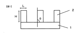
Classifications
-
- G—PHYSICS
- G02—OPTICS
- G02B—OPTICAL ELEMENTS, SYSTEMS OR APPARATUS
- G02B5/00—Optical elements other than lenses
- G02B5/20—Filters
-
- G—PHYSICS
- G03—PHOTOGRAPHY; CINEMATOGRAPHY; ANALOGOUS TECHNIQUES USING WAVES OTHER THAN OPTICAL WAVES; ELECTROGRAPHY; HOLOGRAPHY
- G03F—PHOTOMECHANICAL PRODUCTION OF TEXTURED OR PATTERNED SURFACES, e.g. FOR PRINTING, FOR PROCESSING OF SEMICONDUCTOR DEVICES; MATERIALS THEREFOR; ORIGINALS THEREFOR; APPARATUS SPECIALLY ADAPTED THEREFOR
- G03F7/00—Photomechanical, e.g. photolithographic, production of textured or patterned surfaces, e.g. printing surfaces; Materials therefor, e.g. comprising photoresists; Apparatus specially adapted therefor
- G03F7/004—Photosensitive materials
- G03F7/027—Non-macromolecular photopolymerisable compounds having carbon-to-carbon double bonds, e.g. ethylenic compounds
-
- G—PHYSICS
- G03—PHOTOGRAPHY; CINEMATOGRAPHY; ANALOGOUS TECHNIQUES USING WAVES OTHER THAN OPTICAL WAVES; ELECTROGRAPHY; HOLOGRAPHY
- G03F—PHOTOMECHANICAL PRODUCTION OF TEXTURED OR PATTERNED SURFACES, e.g. FOR PRINTING, FOR PROCESSING OF SEMICONDUCTOR DEVICES; MATERIALS THEREFOR; ORIGINALS THEREFOR; APPARATUS SPECIALLY ADAPTED THEREFOR
- G03F7/00—Photomechanical, e.g. photolithographic, production of textured or patterned surfaces, e.g. printing surfaces; Materials therefor, e.g. comprising photoresists; Apparatus specially adapted therefor
- G03F7/20—Exposure; Apparatus therefor
- G03F7/22—Exposing sequentially with the same light pattern different positions of the same surface
-
- G—PHYSICS
- G09—EDUCATION; CRYPTOGRAPHY; DISPLAY; ADVERTISING; SEALS
- G09F—DISPLAYING; ADVERTISING; SIGNS; LABELS OR NAME-PLATES; SEALS
- G09F9/00—Indicating arrangements for variable information in which the information is built-up on a support by selection or combination of individual elements
- G09F9/30—Indicating arrangements for variable information in which the information is built-up on a support by selection or combination of individual elements in which the desired character or characters are formed by combining individual elements
- G09F9/33—Indicating arrangements for variable information in which the information is built-up on a support by selection or combination of individual elements in which the desired character or characters are formed by combining individual elements being semiconductor devices, e.g. diodes
-
- G—PHYSICS
- G09—EDUCATION; CRYPTOGRAPHY; DISPLAY; ADVERTISING; SEALS
- G09F—DISPLAYING; ADVERTISING; SIGNS; LABELS OR NAME-PLATES; SEALS
- G09F9/00—Indicating arrangements for variable information in which the information is built-up on a support by selection or combination of individual elements
- G09F9/30—Indicating arrangements for variable information in which the information is built-up on a support by selection or combination of individual elements in which the desired character or characters are formed by combining individual elements
- G09F9/35—Indicating arrangements for variable information in which the information is built-up on a support by selection or combination of individual elements in which the desired character or characters are formed by combining individual elements being liquid crystals
-
- H—ELECTRICITY
- H01—ELECTRIC ELEMENTS
- H01L—SEMICONDUCTOR DEVICES NOT COVERED BY CLASS H10
- H01L33/00—Semiconductor devices having potential barriers specially adapted for light emission; Processes or apparatus specially adapted for the manufacture or treatment thereof or of parts thereof; Details thereof
- H01L33/48—Semiconductor devices having potential barriers specially adapted for light emission; Processes or apparatus specially adapted for the manufacture or treatment thereof or of parts thereof; Details thereof characterised by the semiconductor body packages
- H01L33/50—Wavelength conversion elements
-
- H—ELECTRICITY
- H01—ELECTRIC ELEMENTS
- H01L—SEMICONDUCTOR DEVICES NOT COVERED BY CLASS H10
- H01L33/00—Semiconductor devices having potential barriers specially adapted for light emission; Processes or apparatus specially adapted for the manufacture or treatment thereof or of parts thereof; Details thereof
- H01L33/48—Semiconductor devices having potential barriers specially adapted for light emission; Processes or apparatus specially adapted for the manufacture or treatment thereof or of parts thereof; Details thereof characterised by the semiconductor body packages
- H01L33/58—Optical field-shaping elements
-
- H—ELECTRICITY
- H05—ELECTRIC TECHNIQUES NOT OTHERWISE PROVIDED FOR
- H05B—ELECTRIC HEATING; ELECTRIC LIGHT SOURCES NOT OTHERWISE PROVIDED FOR; CIRCUIT ARRANGEMENTS FOR ELECTRIC LIGHT SOURCES, IN GENERAL
- H05B33/00—Electroluminescent light sources
- H05B33/10—Apparatus or processes specially adapted to the manufacture of electroluminescent light sources
-
- H—ELECTRICITY
- H05—ELECTRIC TECHNIQUES NOT OTHERWISE PROVIDED FOR
- H05B—ELECTRIC HEATING; ELECTRIC LIGHT SOURCES NOT OTHERWISE PROVIDED FOR; CIRCUIT ARRANGEMENTS FOR ELECTRIC LIGHT SOURCES, IN GENERAL
- H05B33/00—Electroluminescent light sources
- H05B33/12—Light sources with substantially two-dimensional radiating surfaces
-
- H—ELECTRICITY
- H10—SEMICONDUCTOR DEVICES; ELECTRIC SOLID-STATE DEVICES NOT OTHERWISE PROVIDED FOR
- H10K—ORGANIC ELECTRIC SOLID-STATE DEVICES
- H10K50/00—Organic light-emitting devices
-
- H—ELECTRICITY
- H10—SEMICONDUCTOR DEVICES; ELECTRIC SOLID-STATE DEVICES NOT OTHERWISE PROVIDED FOR
- H10K—ORGANIC ELECTRIC SOLID-STATE DEVICES
- H10K59/00—Integrated devices, or assemblies of multiple devices, comprising at least one organic light-emitting element covered by group H10K50/00
Definitions
- the present invention relates to a resin composition, a light-shielding film formed from the resin composition, a method for manufacturing the light-shielding film, a substrate with partition walls having patterned partition walls, and a display device.
- a color display device with high light utilization efficiency a color display device including a wavelength conversion section made of a wavelength conversion phosphor, a polarization separation means, and a polarization conversion means has been proposed (see, for example, Patent Document 1). ).
- a blue light source a liquid crystal element, a phosphor that emits red fluorescence when excited by blue light, a phosphor that emits green fluorescence when excited by blue light, and a light scattering layer that scatters blue light.
- a color display device including a conversion unit has been proposed (see, for example, Patent Document 2).
- color filters containing color-converting phosphors such as those described in Patent Documents 1 and 2
- generate fluorescence in all directions resulting in low light extraction efficiency and insufficient brightness.
- high-definition display devices called 4K and 8K
- the problem of brightness becomes significant, and higher brightness is required.
- barrier ribs having both high reflectivity and high light-shielding properties
- the inventors first prepared a material obtained by adding a black pigment to a white barrier rib material using a titanium oxide white pigment that exhibits high reflectance. Considered how to use it. However, in this method, the entire exposure light is absorbed by the white pigment and the black pigment, and the light does not reach the bottom of the film during exposure, resulting in poor pattern workability.
- the inventors devised a design in which the exposure light is transmitted during the process of pattern exposure after film formation, and the light shielding property is increased after heating the exposed film at a temperature of 120°C or higher and 250°C or lower.
- a resin composition containing a resin, an organometallic compound containing at least one metal selected from the group consisting of silver, gold, platinum and palladium, a photopolymerization initiator or a quinonediazide compound, and a solvent is used. This was achieved by doing so (see Patent Document 5).
- Patent Document 5 it was found that when an organic palladium compound is used, palladium oxide particles are produced after heating to effectively turn the film black, thereby increasing the light shielding property against visible light.
- the inventors have found that when an organic silver compound is used, the film turns yellow due to the formation of silver nanoparticles after heating, and the blue light shielding property increases.
- the reducing agent is It promotes the production of silver nanoparticles, has excellent weather resistance even under low-temperature heating conditions of about 100 to 120 ° C., and can form barrier ribs that have both high light blocking properties for blue light and high reflectivity for all visible light. We found that (see Patent Document 6).
- this technology has the problem that although the blue light shielding property is improved by the generation of yellow silver nanoparticles, the light shielding property of green to red light (wavelength range 500 nm to 630 nm) is not improved.
- the above-mentioned technology using an organic palladium compound has problems in that the organic palladium compound is expensive and that palladium oxide particles cannot be generated under low temperature heating conditions of about 100 to 120 ° C., and the light shielding property is not improved. Ta.
- the present invention provides a relatively inexpensive resin composition capable of forming gray partition walls having both high reflectivity and high light shielding performance for all visible light even under low-temperature heating conditions of about 100 to 120°C. for the purpose.
- the present invention is as follows.
- the resin composition according to (1), wherein the white pigment is treated with ZrO2 , Al2O3 and SiO2 .
- the resin composition according to (1), wherein the weight ratio of the blue pigment and the purple pigment is 20/80 to 80/20.
- a resin composition containing a photosensitive agent, a white pigment, and a yellow precursor compound, wherein the white pigment is at least one selected from the group consisting of SiO 2 and Al 2 O 3 and ZrO 2 A resin composition characterized by being treated.
- the resin composition according to (1) or (5), wherein the yellow precursor compound is an organic silver compound.
- a film-forming step of applying the resin composition according to (1) or (5) onto a base substrate and drying to obtain a dry film, an exposure step of pattern-exposing the obtained dry film, and a post-exposure A method for producing a light-shielding film comprising a developing step of dissolving and removing a portion soluble in a developer in a dry film and a heating step of curing the dry film after development by heating, wherein in the heating step, after development, A method for producing a light-shielding film, wherein the dry film is heated at a temperature of 100° C. or more and 250° C.
- a substrate with partition walls containing silver and/or silver particles (16)
- a substrate with partitions having (A-1) patterned partitions on a base substrate, wherein the patterned partitions are composed of a resin, a white pigment, a blue pigment and a purple pigment, and an oxidized The substrate with partition walls according to (13), containing silver and/or silver particles.
- a barrier rib-attached substrate having (A-1) patterned barrier ribs on a base substrate, wherein the patterned barrier ribs are composed of a resin, a white pigment, a blue pigment and a purple pigment, and an oxidized
- the substrate with partition walls according to (18) further comprising a color filter having a thickness of 1 to 5 ⁇ m between the base substrate and (B) the pixel layer containing the color-converting luminescent material.
- a display device comprising the substrate with partition walls according to (13) and a light source selected from a liquid crystal cell, an organic EL cell, a mini-LED cell and a micro-LED cell.
- the resin composition of the present invention contains a resin, a photosensitive agent, a white pigment, a yellow precursor compound, and a blue pigment and a violet pigment. is heated at a temperature of 100° C. or higher and 250° C. or lower, yellow particles are generated in the film, and it is possible to form a fine thick-film gray partition pattern that achieves both high reflectivity and high light shielding for all visible light.
- FIG. 1 is a cross-sectional view showing one embodiment of a substrate with partitions of the present invention having patterned partitions.
- FIG. 1 is a cross-sectional view showing one embodiment of a substrate with partitions of the present invention having pixels containing patterned partitions and a color-converting luminescent material;
- FIG. 2 is a cross-sectional view showing one embodiment of the partition-attached substrate of the present invention, which has patterned partitions, a color-converting luminescent material, and light-shielding partitions.
- FIG. 2 is a cross-sectional view showing one embodiment of the substrate with partitions of the present invention, which has patterned partitions, a color-converting luminescent material, and a color filter.
- FIG. 1 is a cross-sectional view showing one embodiment of a substrate with partitions of the present invention having patterned partitions.
- FIG. 1 is a cross-sectional view showing one embodiment of a substrate with partitions of the present invention having pixels containing patterned partitions and a
- FIG. 2 is a cross-sectional view showing one embodiment of the substrate with partitions of the present invention, which has patterned partitions, color-converting luminescent material, light-shielding partitions, and color filters.
- 1 is a cross-sectional view showing one embodiment of a substrate with partitions of the present invention having pixels containing patterned partitions and light-emitting light sources selected from organic EL cells, mini-LED cells, and micro-LED cells.
- FIG. 2 is a cross-sectional view showing the configuration of a display device used for color mixture evaluation in Examples.
- the resin composition of the present invention can be suitably used as a material for forming partitions separating color-converting phosphors, light-emitting light sources selected from organic EL cells, mini-LED cells, and micro-LED cells.
- the resin composition of the present invention is a resin composition containing a resin, a photosensitive agent, a white pigment, a yellow precursor compound and a light-shielding pigment, wherein the light-shielding pigment is a resin composition containing a blue pigment and a violet pigment. be.
- the resin composition of the present invention is a resin composition containing a photosensitizer, a white pigment, and a yellow precursor compound, wherein the white pigment is at least one selected from the group consisting of SiO 2 and Al 2 O 3 . 1 and ZrO 2 are treated resin compositions.
- This resin composition preferably further contains a light-shielding pigment.
- Resin Resin has the function of improving the crack resistance and light resistance of the partition walls.
- the content of the resin in the solid content of the resin composition is preferably 10% by weight or more, more preferably 20% by weight or more, from the viewpoint of improving the crack resistance of the partition walls during heat treatment.
- the resin content in the solid content of the resin composition is preferably 60% by weight or less, more preferably 50% by weight or less.
- the solid content means all the components excluding volatile components such as solvent among the components contained in the resin composition. The amount of solids can be determined by heating the resin composition to evaporate volatile components and weighing the residue.
- resins examples include polysiloxane, polyimide, polyimide precursors, polybenzoxazole, polybenzoxazole precursors, and (meth)acrylic polymers.
- (meth)acrylic polymer means a polymer of methacrylic acid ester and/or acrylic acid ester. You may contain 2 or more types of these. Among these, polysiloxane is preferable because it is excellent in heat resistance and light resistance.
- Polysiloxane is a hydrolysis/dehydration condensate of organosilane.
- the polysiloxane preferably contains at least a repeating unit represented by the following general formula (1). Further, other repeating units may be included.
- repeating units derived from the bifunctional alkoxysilane compound represented by the general formula (1) excessive thermal polymerization (condensation) of polysiloxane due to heating can be suppressed, and the crack resistance of the partition walls can be improved. It is preferable that the polysiloxane contains 10 to 80 mol % of repeating units represented by the general formula (1) in all repeating units.
- the crack resistance can be further improved.
- the content of the repeating unit represented by formula (1) is more preferably 12.5 mol % or more, and even more preferably 15 mol % or more.
- the molecular weight of the polysiloxane can be sufficiently increased during polymerization, and the coatability can be improved.
- the content of the repeating unit represented by formula (1) is more preferably 70 mol % or less.
- R 1 and R 2 which may be the same or different, each represent a monovalent organic group having 1 to 20 carbon atoms.
- R 1 and R 2 are preferably groups selected from alkyl groups having 1 to 6 carbon atoms and aryl groups having 6 to 12 carbon atoms, from the viewpoint of facilitating adjustment of the molecular weight of polysiloxane during polymerization.
- at least part of the hydrogen atoms may be substituted with a radically polymerizable group.
- the radically polymerizable group may be radically polymerized in the cured product of the negative photosensitive resin composition.
- the polysiloxane preferably further contains a repeating unit represented by the following general formula (2).
- a repeating unit represented by the following general formula (2) By including the repeating unit derived from the trifunctional alkoxysilane compound represented by the general formula (2), the crosslink density of the polysiloxane increases after film formation, and the hardness and chemical resistance of the film can be improved. It is preferable that the polysiloxane contains 10 to 80 mol % of repeating units represented by the general formula (2) in all repeating units. The content of the repeating unit represented by formula (2) is more preferably 15 mol % or more, and even more preferably 20 mol % or more.
- the repeating unit represented by the general formula (2) by including 80 mol % or less of the repeating unit represented by the general formula (2), excessive thermal polymerization (condensation) of polysiloxane due to heating can be suppressed, and the crack resistance of the partition walls can be improved.
- the content of the repeating unit represented by formula (2) is more preferably 70 mol % or less.
- R 3 represents a monovalent organic group having 1 to 20 carbon atoms. Two or more types of repeating units represented by the general formula (2) having different R3 may be included in the polysiloxane.
- R 3 preferably contains a group selected from an alkyl group having 1 to 6 carbon atoms and an aryl group having 6 to 12 carbon atoms, from the viewpoint of facilitating adjustment of the molecular weight of polysiloxane during polymerization.
- the alkyl group and the aryl group at least part of the hydrogen atoms may be substituted with a radically polymerizable group.
- the radically polymerizable group may be radically polymerized in the cured product of the negative photosensitive resin composition.
- the repeating units represented by the general formulas (1) and (2) are derived from alkoxysilane compounds represented by the following general formulas (3) and (4), respectively. That is, polysiloxane containing repeating units represented by the general formulas (1) and (2) is hydrolyzed and alkoxysilane compounds containing alkoxysilane compounds represented by the following general formulas (3) and (4). It can be obtained by polycondensation. Other alkoxysilane compounds may also be used.
- "-(OR 4 ) 2 " and "-(OR 4 ) 3 " represent two and three Si atoms with "-(OR 4 )", respectively. It means that they are individually connected.
- R 1 to R 2 represent the same groups as R 1 to R 2 in general formula (1) above.
- R 3 represents the same group as R 3 in general formula (2) above.
- R 4 which may be the same or different, represents a monovalent organic group having 1 to 20 carbon atoms or hydrogen, preferably an alkyl group having 1 to 6 carbon atoms.
- alkoxysilane compound represented by the general formula (3) examples include dimethyldimethoxysilane, dimethyldiethoxysilane, diphenyldimethoxysilane, diphenyldiethoxysilane, diphenylsilanediol, styrylmethyldimethoxysilane, styrylmethyldiethoxysilane, ⁇ -Methacryloylpropylmethyldimethoxysilane, ⁇ -Methacryloylpropylmethyldiethoxysilane, ⁇ -Acryloylpropylmethyldimethoxysilane, ⁇ -Acryloylpropylmethyldiethoxysilane, 3-Glycidoxypropylmethyldimethoxysilane, 3-Glycidoxypropyl methyldiethoxysilane, 2-(3,4-epoxycyclohexyl)ethylmethyldimethoxysilane, 2-(3,4-epoxycyclohexyl
- alkoxysilane compounds represented by general formula (4) include methyltrimethoxysilane, methyltriethoxysilane, ethyltrimethoxysilane, ethyltriethoxysilane, propyltrimethoxysilane, propyltriethoxysilane, isobutyltrimethoxysilane, Silane, isobutyltriethoxysilane, cyclohexyltrimethoxysilane, cyclohexyltriethoxysilane, 3-ureidopropyltrimethoxysilane, 3-ureidopropyltriethoxysilane, 3-glycidoxypropyltrimethoxysilane, 3-glycidoxypropyltri Ethoxysilane, 2-(3,4-epoxycyclohexyl)ethyltrimethoxysilane, 2-(3,4-epoxycyclohexyl)ethyltrieth
- the resin composition of the present invention contains at least one radically polymerizable group-containing alkoxysilane compound as the alkoxysilane compound represented by general formulas (3) and/or (4). is preferred.
- the radically polymerizable group-containing alkoxysilane compound By containing the radically polymerizable group-containing alkoxysilane compound, a crosslinking reaction proceeds with the radicals generated in the exposed area, and the degree of curing of the exposed area can be increased.
- the resin composition of the present invention contains at least one carboxyl group-containing alkoxysilane compound as the alkoxysilane compound represented by the general formulas (3) and/or (4). is preferred. Containing a carboxyl group-containing alkoxysilane compound improves the solubility of the unexposed area, and can improve the resolution during pattern processing.
- alkoxysilane compounds may be contained as raw materials for polysiloxane.
- alkoxysilane compounds include tetrafunctional alkoxysilane compounds such as tetramethoxysilane, tetraethoxysilane, and silicate 51 (tetramethoxysilane oligomer). You may use 2 or more types of these.
- the content of the alkoxysilane compound represented by the general formula (3) in the alkoxysilane compound that is the raw material of the polysiloxane is the content of the repeating unit represented by the general formula (1) in all the repeating units of the polysiloxane. From the viewpoint of setting the amount within the above range, it is preferably 10 mol % or more, more preferably 12.5 mol % or more, and even more preferably 15 mol % or more. On the other hand, from the same viewpoint, the content of the alkoxysilane compound represented by the general formula (4) is preferably 80 mol % or less, more preferably 70 mol % or less.
- the polysiloxane in the resin composition of the present invention preferably has a styryl group.
- a styryl group By having a styryl group, curing can be sufficiently accelerated even under low-temperature curing conditions of 85°C to 120°C.
- the weight average molecular weight (Mw) of polysiloxane is preferably 1,000 or more, more preferably 2,000 or more, from the viewpoint of coatability.
- Mw of polysiloxane is preferably 500,000 or less, more preferably 300,000 or less.
- the Mw of polysiloxane in the present invention refers to a polystyrene conversion value measured by gel permeation chromatography (GPC). The measuring method is as described in Examples below.
- Polysiloxane can be obtained by hydrolyzing the aforementioned organosilane compound and then subjecting the hydrolyzate to a dehydration condensation reaction in the presence or absence of a solvent.
- the resin composition of the present invention When the resin composition of the present invention is used for pattern formation of partition walls (A-1) described below, it preferably has negative or positive photosensitivity.
- the resin composition of the present invention preferably contains a photosensitizer.
- a photopolymerization initiator When imparting negative photosensitivity, it is preferable to contain a photopolymerization initiator as a photosensitizer, so that partition walls having a highly precise pattern can be formed.
- the negative photosensitive resin composition preferably further contains a photopolymerizable compound.
- Any photopolymerization initiator can be used as long as it decomposes and/or reacts with irradiation of light (including ultraviolet rays and electron beams) to generate radicals.
- 2-methyl-[4-(methylthio)phenyl]-2-morpholinopropan-1-one 2-dimethylamino-2-(4-methylbenzyl)-1-(4-morpholin-4-yl ⁇ -Aminoalkylphenone compounds such as -phenyl)-butan-1-one, 2-benzyl-2-dimethylamino-1-(4-morpholinophenyl)-butanone-1; 2,4,6-trimethylbenzoylphenyl Acylphosphine oxide compounds such as phosphine oxide, bis(2,4,6-trimethylbenzoyl)-phenylphosphine oxide, bis(2,6-dimethoxybenzoyl)-(2,4,4-trimethylpentyl)-phosphine oxide ; 1-phenyl
- the content of the photopolymerization initiator in the resin composition of the present invention is preferably 0.01% by weight or more, more preferably 1% by weight or more, based on the solid content.
- the content of the photopolymerization initiator is preferably 20% by weight or less, more preferably 10% by weight or less, based on the solid content, from the viewpoint of suppressing elution of the remaining photopolymerization initiator.
- the photopolymerizable compound in the present invention refers to a compound having two or more ethylenically unsaturated double bonds in its molecule. Considering the easiness of radical polymerization, the photopolymerizable compound preferably has a (meth)acrylic group.
- photopolymerizable compounds include pentaerythritol triacrylate, pentaerythritol tetraacrylate, pentaerythritol trimethacrylate, pentaerythritol tetramethacrylate, dipentaerythritol pentaacrylate, and dipentaerythritol hexaacrylate. You may contain 2 or more types of these.
- the content of the photopolymerizable compound in the resin composition of the present invention is preferably 1% by weight or more based on the solid content.
- the content of the photopolymerizable compound is preferably 50% by weight or less in the solid content.
- quinonediazide compound a compound in which the sulfonic acid of naphthoquinonediazide is bonded to a compound having a phenolic hydroxyl group via an ester is preferable.
- Compounds having a phenolic hydroxyl group used here include, for example, BIs-Z, TekP-4HBPA (tetrakis P-DO-BPA), TrIsP-HAP, TrIsP-PA, BIsRS-2P, BIsRS-3P (the above, commercial products name, manufactured by Honshu Chemical Industry Co., Ltd.), BIR-PC, BIR-PTBP, BIR-BIPC-F (trade names, manufactured by Asahi Organic Chemicals Industry Co., Ltd.), 4,4'-sulfonyldiphenol, BPFL (trade name, manufactured by JFE Chemical Co., Ltd.).
- quinonediazide compound those obtained by introducing 4-naphthoquinonediazide sulfonic acid or 5-naphthoquinonediazide sulfonic acid into these compounds having a phenolic hydroxyl group via an ester bond are preferable. manufactured by Toyo Gosei Co., Ltd.), SBF-525 (trade name, manufactured by AZ Electronic Materials Co., Ltd.), and the like.
- the content of the quinonediazide compound in the resin composition of the present invention is preferably 0.5% by weight or more, more preferably 1% by weight or more, based on the solid content.
- the content of the quinonediazide compound is preferably 25% by weight or less, more preferably 20% by weight or less, based on the solid content, from the viewpoint of improving resolution.
- the resin composition of the present invention preferably further contains a white pigment.
- a white pigment has a function of further improving the reflectance of the partition wall.
- white pigments examples include titanium dioxide, zirconium oxide, zinc oxide, barium sulfate, and composite compounds thereof. You may contain 2 or more types of these. Among these, titanium dioxide is preferable because of its high reflectance and easy industrial use.
- the crystal structure of titanium dioxide is classified into anatase, rutile and brookite types. Among these, rutile-type titanium oxide is preferable because of its low photocatalytic activity.
- the white pigment may be surface-treated. Surface treatment with a metal selected from Al, Si and Zr is preferable, and the light resistance and heat resistance of the formed partition walls can be improved. More preferably, the white pigment is treated with at least one selected from the group consisting of SiO 2 and Al 2 O 3 and ZrO 2 , and the white pigment is treated with ZrO 2 , Al 2 O 3 and SiO 2 More preferably, it is surface-treated. From the viewpoint of light resistance and reflectivity, the white pigment is more preferably titanium dioxide surface-treated with ZrO 2 , Al 2 O 3 and SiO 2 .
- the particle diameter D50 of the white pigment based on scattered light is preferably 100 to 500 nm, more preferably 150 to 350 nm, from the viewpoint of further improving the reflectance of the partition walls.
- the particle diameter D50 of the white pigment can be measured using a particle size distribution analyzer (SZ-100; manufactured by HORIBA Ltd.) or the like.
- the average primary particle size of the white pigment is preferably 100 to 500 nm, more preferably 150 nm to 350 nm, from the viewpoint of further improving the reflectance of the partition walls.
- the average primary particle size of the white pigment can be measured by a laser diffraction method using a particle size distribution analyzer (N4-PLUS; manufactured by Beckman Coulter, Inc.).
- Titanium dioxide pigments preferably used as white pigments include, for example, R960 manufactured by DuPont (rutile type, SiO 2 /Al 2 O 3 treatment, average primary particle size 210 nm), R996 manufactured by Ronmon Billions Co., Ltd. (rutile type, ZrO 2 /Al 2 O 3 treatment, average primary particle size 230 nm), CR-97; manufactured by Ishihara Sangyo Co., Ltd. (rutile type, Al 2 O 3 /ZrO 2 treatment, average primary particle size 250 nm) , PFC105; manufactured by Ishihara Sangyo Co., Ltd.
- the content of the white pigment in the resin composition is preferably 10% by weight or more, more preferably 15% by weight or more, based on the solid content, from the viewpoint of further improving the reflectance.
- the content of the white pigment is preferably 60% by weight or less, more preferably 55% by weight or less in the solid content.
- the resin composition of the present invention preferably further contains a yellow precursor compound.
- a yellow precursor compound refers to a compound that absorbs light in the wavelength region of 380 nm to 500 nm and becomes yellowish due to reaction, decomposition, structural change, or the like due to heat and/or light energy. In particular, it is preferable that the absorption at a wavelength of 450 nm increases.
- the blue light shielding property of the partition wall can be improved. If the resin composition contains a yellow component from the beginning, the exposure light is greatly absorbed in the exposure step when forming the partition wall (A-1) pattern, which will be described later, and the exposure light does not reach the bottom, and curing does not proceed.
- the exposure light is transmitted and curing progresses to the bottom, so that it is possible to form a fine thick film barrier rib pattern with high blue light shielding properties. Therefore, it is more preferable that the light absorption in the wavelength range of 380 nm to 500 nm does not change in the exposure process and the light absorption in the wavelength range of 380 nm to 500 nm increases in the subsequent heating process.
- yellow precursor compounds examples include phenolic compounds, organic polymer resins, and organometallic compounds. Organometallic compounds are preferred from the viewpoint of the light resistance of the resulting yellow component.
- Phenolic compounds are oxidized by heat and/or light energy to produce quinone compounds. It is preferred to use a phenolic compound that produces a yellow quinone compound. Examples of phenolic compounds include 1,4-dihydroxynaphthalene, 1,4-dihydroxyanthrahydroquinone, quinizarin, 1,4-dihydroxy-2-sulfoanthraquinone and the like. You may contain 2 or more types of these.
- the organic polymer resin is not particularly limited as long as it yellows due to heat and/or light energy.
- organic polymer resins include polyolefins such as polyethylene and polypropylene, polyvinyl chloride, polycarbonate, and ABS resins. You may contain 2 or more types of these.
- Polyolefin turns yellow when hydrogen in its structure is extracted by heat or light, and polyene is generated by an oxidation reaction.
- Polyvinyl chloride turns yellow due to the progress of dehydrochlorination reaction due to heat or light and the increase in conjugated double bonds such as polyene.
- Polycarbonate turns yellow by producing a phenylsalicylate structure and further a dihydroxybenzophenone structure by a photoreaction called Fries transition.
- ABS resin is known to yellow due to radical species generated by oxidation due to heat or light.
- the organometallic compound is not particularly limited as long as it produces yellow particles with absorption in the range of 380 nm to 500 nm by heat and/or light energy.
- yellow particles having absorption at 380 nm to 500 nm include iron oxide particles, copper oxide particles, iridium oxide particles, bismuth oxide, tungsten oxide, gold oxide particles, nano gold particles, silver oxide and/or silver particles, silver nano
- organic metal compounds include organic iron compounds, organic copper compounds, organic iridium compounds, organic bismuth compounds, organic tungsten compounds, organic gold compounds, and organic silver compounds. Two or more of these may be included.
- the yellow precursor compound is preferably an organic silver compound from the viewpoint that it can be produced to improve the light-shielding properties of the film.
- organic iron compounds include tris(2,4-pentadionato)iron, ferrocene, iron cyanide, iron carbonate, iron pentacarbonyl, iron oxalate, iron nonacarbonyl, iron acetate, iron formate, hexacyanide ferrate, and the like.
- organic copper compounds include bis(2,4-pentadionato)copper, copper neodecanoate, copper acetate, copper formate, copper formate hydrate, copper oxalate, and copper oxalate hydrate.
- organic iridium compounds include tris(2,4-pentadionato)iridium, dodecacarbonyltetrairidium, bis(triphenylphosphine)iridiumcarbonyl chloride, and idridocene.
- organic bismuth compounds include bismuth subcarbonate, bismuth carbonate, bismuth subgallate and the like.
- organic tungsten compounds include hexacarbonyltungsten and hexamethyltungsten.
- Organic gold compounds include chloro(triphenylphosphine) gold, gold resinate MR7901-P, tetrachloroauric acid tetrahydrate, and the like.
- organic silver compounds examples include those described in paragraphs [0048] to [0049] of JP-A-10-62899, page 18, line 24 to page 19, line 37 of European Patent Application Publication No. 803,764A1.
- organic silver compounds and aliphatic carbons Examples include silver salts of acids.
- a compound represented by the following general formula (5) and/or a polymer compound having a structure represented by the following general formula (6) is preferable from the viewpoint of further yellowing.
- R 5 represents hydrogen or an organic group having 1 to 30 carbon atoms.
- the "organic group having 1 to 30 carbon atoms” includes an alkyl group having 1 to 30 carbon atoms (including linear and branched alkyl groups) and/or an aromatic carbonized group having 6 to 30 carbon atoms.
- a hydrogen group is preferred.
- Preferred specific examples thereof include methyl group, ethyl group, n-propyl group, isopropyl group, n-butyl group, isobutyl group, n-pentyl group, isopentyl group, n-hexyl group, isohexyl group, n-heptyl group, isoheptyl group, n-octyl group, isooctyl group, n-nonyl group, isononyl group, decyl group, undecyl group, dodecyl group, tridecyl group, tetradecyl group, pentadecyl group, hexadecyl group, heptadecyl group, octadecyl group, nonadecyl group, eicosyl phenyl, benzyl, tolyl, biphenyl and naphthyl radicals.
- R 6 and R 7 each independently represent hydrogen or an organic group having 1 to 30 carbon atoms.
- the "organic group having 1 to 30 carbon atoms” includes an alkyl group having 1 to 30 carbon atoms (including linear and branched alkyl groups) and/or an aromatic carbonized group having 6 to 30 carbon atoms.
- a hydrogen group is preferred.
- Preferred specific examples thereof include methyl group, ethyl group, n-propyl group, isopropyl group, n-butyl group, isobutyl group, n-pentyl group, isopentyl group, n-hexyl group, isohexyl group, n-heptyl group, isoheptyl group, n-octyl group, isooctyl group, n-nonyl group, isononyl group, decyl group, undecyl group, dodecyl group, tridecyl group, tetradecyl group, pentadecyl group, hexadecyl group, heptadecyl group, octadecyl group, nonadecyl group, eicosyl phenyl, benzyl, tolyl, biphenyl and naphthyl radicals. Also, a is an integer
- Examples of organic silver compounds represented by formula (5) include silver acetate, silver propionate, silver butyrate, silver valerate, silver hexanoate, silver enanthate, silver octylate, silver pelargonate, and silver caprate.
- the organic silver compound represented by the general formula (6) has a structure in which the carboxyl group in a (meth)acrylic polymer having a carboxyl group has become a silver salt.
- the organic silver compound represented by the general formula (6) is obtained, for example, by stirring a (meth)acrylic polymer having a carboxyl group and silver nitrate in an organic solvent in the presence of an amine catalyst, as in the preparation examples described below. be done.
- the (meth)acrylic polymer having a carboxyl group is obtained by polymerizing an unsaturated carboxylic acid.
- unsaturated carboxylic acids include acrylic acid, methacrylic acid, itaconic acid, crotonic acid, maleic acid, fumaric acid, vinylacetic acid, and acid anhydrides. These may be used alone, or may be used in combination with other copolymerizable ethylenically unsaturated compounds.
- copolymerizable ethylenically unsaturated compounds include methyl acrylate, methyl methacrylate, ethyl acrylate, ethyl methacrylate, n-propyl acrylate, isopropyl acrylate, n-propyl methacrylate, and methacrylic acid.
- carboxylic acid vinyl esters vinyl cyanide compounds such as acrylonitrile, methacrylonitrile and ⁇ -chloroacrylonitrile, aliphatic conjugated dienes such as 1,3-butadiene and isoprene, polystyrenes having acryloyl groups or methacryloyl groups at their ends, Examples include, but are not limited to, macromonomers such as polymethyl acrylate, polymethyl methacrylate, polybutyl acrylate, polybutyl methacrylate, and polysilicone.
- the (meth)acrylic polymer is not particularly limited.
- a commercially available product may be used as the (meth)acrylic polymer having a carboxyl group.
- Commercially available (meth)acrylic polymers having a carboxyl group include, for example, AX3-BX-TR-101, AX3-BX-TR-102, AX3-BX-TR-106, AX3-BX-TR-107, AX3- BX-TR-108, AX3-BX-TR-109, AX3-BX-TR-110, AX3-RD-TR-501, AX3-RD-TR-502, AX3-RD-TR-503, AX3-RD- TR-504, AX3-RD-TR-103, AX3-RD-TR-104 (trade name, manufactured by Nippon Shokubai Co., Ltd.), SPCR-10X, SPCR-10P, SPCR-24X, SPCR-18X, SPCR-215X ( (trade name, manufactured by Showa Denko KK), X-4007 (trade name, manufactured by NOF Corporation
- the weight average molecular weight (Mw) of the polymer compound represented by the general formula (6) is not particularly limited, but is preferably 5000 to 50000, more preferably 8000 to 35000 in terms of polystyrene measured by GPC. . If Mw is less than 5,000, pattern drooping will occur during heat curing, resulting in lower resolution. On the other hand, when Mw is more than 50,000, it is difficult to be reduced, and it is difficult to form yellow particles.
- the content of the yellow precursor compound in the solid content of the resin composition is preferably 0.1% by weight or more, more preferably 0.4% by weight or more.
- the partition walls obtained can be made more yellow, and the blue light shielding properties of the partition walls are improved.
- the content of the yellow precursor compound in the solid content of the resin composition is preferably 10% by weight or less, more preferably 5.0% by weight or less.
- Light-shielding pigment The resin composition of the present invention preferably further contains a light-shielding pigment.
- the light-shielding pigment has a function of further improving the light-shielding property of the partition wall against light of a specific wavelength.
- the light-shielding pigment preferably contains a blue pigment and a violet pigment.
- a blue pigment and a violet pigment it is possible to improve the light-shielding property of the film in a wavelength range of 500 nm to 630 nm (green light to red light).
- the blue pigment and purple pigment are selected from inorganic pigments, organic pigments, and mixed pigments thereof, and the ingredients are not particularly limited.
- Blue pigments include, for example, Pigment Blue (hereinafter abbreviated as PB) 1, PB9, PB18, PB25, PB28, PB29, PB36, PB15, PB15:1, PB15:2, PB15:3, PB15:4, PB15:6 , PB17:1, PB60, PB66, PB75, PB79 and the like. You may contain 2 or more types of these. Among these, the phthalocyanine pigments PB15, PB15:1, PB15:2, PB15:3, PB15:4 and PB15:6 are preferred, and PB15:6 is more preferred, from the viewpoint of excellent light resistance.
- PB Pigment Blue
- purple pigments examples include pigment violet (hereinafter abbreviated as PV) 1, PV3, PV3:3, PV19, PV23, PV29, PV37, PV38, PV39, and PV50.
- PV19, PV23, PV29, PV37, and PV38, which are condensed polycyclic pigments are preferable from the viewpoint of excellent heat resistance
- PV23, PV29, and PV37 are more preferable from the viewpoint of excellent light-shielding properties in the wavelength region of 500 nm to 550 nm.
- the total content of the blue pigment and the purple pigment in the solid content of the resin composition is preferably 0.01% by weight or more, more preferably 0.05% by weight or more, and even more preferably 0.10% by weight or more.
- the total content of the blue pigment and the violet pigment By setting the total content of the blue pigment and the violet pigment to 0.10% by weight or more, it is possible to further improve the light-shielding properties of the obtained partition wall in the wavelength range of 500 nm to 630 nm (green light to red light).
- the total content of the blue pigment and the purple pigment in the solid content of the resin composition is preferably 3.0% by weight or less, more preferably 1.0% by weight or less, and even more preferably 0.75% by weight or less.
- the weight ratio of the blue pigment and the purple pigment is preferably 20/80 to 80/20.
- the weight ratio of the blue pigment and the violet pigment is more preferably 30/70 to 70/30, still more preferably 50/50 to 65/35.
- the weight of the yellow precursor compound in the solid content of the resin composition of the present invention is 0.2 to 20 with respect to 100 weight of the white pigment, and the blue pigment and the purple pigment in the solid content. It is preferred that the total weight is between 0.05 and 10 per 100 weight of the white pigment. By setting this ratio, it is possible to obtain a gray partition pattern that is excellent in high light shielding properties and high reflectance for the entire visible light (wavelength range of 430 to 630 nm).
- the weight of the yellow precursor compound in the solid content of the resin composition of the present invention is 0.5 to 10 with respect to the weight of the white pigment 100, and the total weight of the blue pigment and the purple pigment in the solid content. is more preferably 0.01 to 5 per 100 weight of the white pigment.
- the resin composition of the present invention may contain, as a light-shielding pigment, a light-shielding pigment other than the blue pigment and the purple pigment.
- a light-shielding pigment include, for example, red pigments, black pigments, green pigments, yellow pigments, and the like.
- red pigments examples include Pigment Red (hereinafter abbreviated as PR) 9, PR177, PR179, PR180, PR192, PR209, PR215, PR216, PR217, PR220, PR223, PR224, PR226, PR227, PR228, PR240, and PR254. mentioned. You may contain 2 or more types of these.
- black pigments include black organic pigments and black inorganic pigments.
- color organic pigments include carbon black, perylene black, aniline black, and benzofuranone pigments. These may be coated with a resin.
- Black inorganic pigments include, for example, graphite; fine particles of metals such as titanium, copper, iron, manganese, cobalt, chromium, nickel, zirconium, zinc, calcium, silver, gold, platinum, and palladium; metal oxides; metal sulfides; metal nitrides; metal oxynitrides; and metal carbides. You may contain 2 or more types of these.
- C.I. I. Pigment Green hereinafter abbreviated as PG 7
- PG36 PG36
- PG58 PG37
- PG59 PG59
- You may contain 2 or more types of these.
- yellow pigments examples include Pigment Yellow (hereinafter abbreviated as PY) PY137, PY138, PY139, PY147, PY148, PY150, PY153, PY154, PY166, PY168, and PY185. You may contain 2 or more types of these.
- PY Pigment Yellow
- the resin composition of the present invention preferably further contains a reducing agent.
- the reducing agent promotes the reduction of the yellow precursor compound (particularly the organic silver compound), thereby more efficiently producing yellow particles, and improves the light-shielding properties of the film even under low-temperature heating conditions of about 100 to 120°C. can be improved.
- the present technology can be applied even in applications where a material such as an organic EL material that is concerned about heat resistance exists as an underlying layer and low-temperature heating conditions are essential.
- an unreacted organic silver compound remains in the film after heating, it will be decomposed by light or heat, and the film color will change, resulting in a film with poor weather resistance. , the amount of the organic silver compound remaining in the film after curing is reduced, and the weather resistance is improved.
- the reducing agent may be any compound as long as it promotes the reduction of the organic silver compound, but from the viewpoint of reducing the organic silver compound more efficiently, it contains two or more phenolic hydroxyl groups in the molecule.
- Compounds or compounds containing enediol groups are preferred.
- Compounds containing two or more phenolic hydroxyl groups in the molecule are themselves oxidized to produce quinone compounds when reducing the organic silver compound, but they produce colored quinone compounds like the above-mentioned yellow precursor compound. A structure that does not generate is preferred.
- Compounds containing two or more phenolic hydroxyl groups in the molecule include, for example, dihydric phenol compounds such as catechol compounds, hydroquinone compounds, resorcinol compounds, anthrahydroquinone compounds, and polyphenols containing three or more phenolic hydroxyl groups. compound.
- dihydric phenol compounds such as catechol compounds, hydroquinone compounds, resorcinol compounds, anthrahydroquinone compounds, and polyphenols containing three or more phenolic hydroxyl groups.
- a hydroquinone compound represented by the following general formula (7) is more preferable from the viewpoint of reducing properties.
- R 8 , R 9 , R 10 and R 11 each independently represent hydrogen, a hydroxy group, or an organic group having 1 to 30 carbon atoms.
- the "organic group having 1 to 30 carbon atoms” includes an alkyl group having 1 to 30 carbon atoms (including linear and branched alkyl groups) and/or an aromatic carbonized group having 6 to 30 carbon atoms.
- a hydrogen group is preferred.
- Preferred specific examples thereof include methyl group, ethyl group, n-propyl group, isopropyl group, n-butyl group, isobutyl group, n-pentyl group, isopentyl group, n-hexyl group, isohexyl group, n-heptyl group, isoheptyl group, n-octyl group, isooctyl group, n-nonyl group, isononyl group, decyl group, undecyl group, dodecyl group, tridecyl group, tetradecyl group, pentadecyl group, hexadecyl group, heptadecyl group, octadecyl group, nonadecyl group, eicosyl phenyl, benzyl, tolyl, biphenyl and naphthyl radicals.
- Hydroquinone compounds represented by the following general formula (7) include, for example, hydroquinone, methylhydroquinone, ethylhydroquinone, propylhydroquinone, butylhydroquinone, t-butylhydroquinone, 2,3-dimethylhydroquinone, 2,3-diethylhydroquinone, 2,3-dipropylhydroquinone, 2,3-dibutylhydroquinone, 2,3-di-t-butylhydroquinone, 2,5-dimethylhydroquinone, 2,5-diethylhydroquinone, 2,5-dipropylhydroquinone, 2,5 -dibutylhydroquinone, 2,5-di-t-butylhydroquinone, hydroquinone dimethyl ether, hydroquinone diethyl ether, 1,2,4-benzenetriol, 2,5-dihydroxyacetophenone, 2,
- Compounds containing an enediol group include, for example, ascorbic acid, ⁇ -pyridoin, fructose, xylose, glucose, dioxyacetone, glycolaldehyde, benzoin, monooxyacetone, and benzoylcarbinol.
- glycolaldehyde is preferable from the viewpoint of reducing properties and solubility in organic solvents.
- the content of the reducing agent in the solid content of the resin composition is preferably 0.01% by weight or more, more preferably 0.1% by weight or more.
- the organic silver compound can be reduced more effectively, the partition walls obtained can be further yellowed, and the blue light blocking properties of the partition walls are improved.
- the amount of the organic silver compound remaining in the film after curing is reduced, improving the weather resistance.
- the content of the reducing agent in the solid content of the resin composition is preferably 3.0% by weight or less, more preferably 1.5% by weight or less.
- the resin composition of the present invention preferably further contains phosphate polyester.
- the phosphate polyester is not particularly limited as long as it is a polymer containing a phosphate group, a polyphosphate group, or a phosphate group.
- Phosphoric polyester has the function of improving the stability of the white pigment and the organic silver compound.
- the phosphoric polyester is preferably used as a dispersing agent when dispersing the pigment.
- Examples of phosphoric polyester include Phosphanol (registered trademark) RA-600, ML-200, ML-220, RS-610, RB-410, RD-720N (manufactured by Toho Chemical Industry Co., Ltd.), Solsperse (registered trademark) SOLSPERSE26000, SOLSPERSE36000, SOLSPERSE41000 (manufactured by ZENECA), “DISPERBYK” (registered trademark)-110, 111, 142, 145, 180, “BYK” (registered trademark)-110, 111, W969, W9010 (above, manufactured by Big Chemie Japan Co., Ltd.), Price Surf (registered trademark) A-208B, A-208F, A-208N, A-219B, DB-01, M208F (above, manufactured by Daiichi Kogyo Seiyaku Co., Ltd.) , Disparon (registered trademark) PW-36, DA-375 (
- Phosphanol ML-220, DISPERBYK-110, DISPERBYK-111 and PLYSURF A-208B are preferable from the viewpoint of improving the stability of the white pigment and the organic silver compound.
- the content of the phosphate polyester in the solid content of the resin composition is preferably 0.50% by weight or more, more preferably 1.0% by weight or more.
- the white pigment and the organic silver compound are stabilized more by setting the content of the phosphoric acid polyester to 0.50% by weight or more.
- the content of the phosphate polyester in the solid content of the resin composition is preferably 15% by weight or less, more preferably 10% by weight or less.
- the resin composition of the present invention preferably further contains a liquid-repellent compound.
- a liquid-repellent compound is a compound that imparts the property of repelling water and organic solvents (liquid-repellent performance) to a resin composition.
- the compound is not particularly limited as long as it has such properties, but specifically, a compound having a fluoroalkyl group is preferably used.
- liquid-repellent performance can be imparted to the top of the partition walls (A-1) described later after the partition walls (A-1) are formed.
- color-converting light-emitting materials having different compositions can be easily applied to each pixel.
- the liquid-repellent compound is preferably a liquid-repellent compound having a photoradical polymerizable group.
- a photoradical polymerizable group By having a photoradical polymerizable group, it is possible to form a strong bond with a resin, so that liquid repellency can be more easily imparted to the top of the partition wall.
- Liquid-repellent compounds having photoradical polymerizable groups include, for example, “Megafac” (registered trademark) RS-72-A, RS-75-A, RS-76-E, RS-56, RS-72-K , RS-75, RS-76-E, RS-76-NS, RS-76, and RS-90 (all trade names, manufactured by DIC Corporation).
- the photopolymerizable group may be photopolymerized in the partition walls (A-1) made of the photocured product of the negative photosensitive resin composition.
- the content of the liquid-repellent compound in the resin composition is preferably 0.01% by weight or more, more preferably 0.1% by weight or more, based on the solid content. more preferred.
- the content of the liquid-repellent compound is preferably 10% by weight or less, more preferably 5% by weight or less, based on the solid content.
- the resin composition of the present invention may further contain an organometallic compound other than the yellow precursor compound.
- an organometallic compound other than the yellow precursor compound an organoplatinum compound or an organopalladium compound is preferred.
- the organoplatinum compound or the organopalladium compound is decomposed and aggregated into black particles in the exposure step and/or the heating step, so that the light shielding property of the film can be further improved without deteriorating the pattern workability. .
- organic platinum compounds include bis(acetylacetonato)platinum, dichlorobis(triphenylphosphine)platinum, and dichlorobis(benzonitrile)platinum.
- organic palladium compounds include bis(acetylacetonato)palladium, dichlorobis(triphenylphosphine)palladium, dichlorobis(benzonitrile)palladium, tetrakis(triphenylphosphine)palladium, and dibenzylideneacetonepalladium. You may contain 2 or more types of these.
- the content of the organometallic compound other than the yellow precursor compound in the solid content is preferably 0.2 to 5% by weight. By making it 0.2% by weight or more, the light shielding property of the obtained film can be further improved. 0.5% by weight or more is more preferable. On the other hand, by setting the content of the organometallic compound other than the yellow precursor compound to 5% by weight or less, the reflectance can be further improved. 3% by weight or less is more preferable.
- the resin composition of the present invention may contain a polymerization inhibitor, a surfactant, an adhesion improver, etc., if necessary.
- surfactants include "Megafac” (registered trademark) F142D, F172, F173, F183, F445, F470, F475, F477 (trade names, manufactured by Dainippon Ink and Chemicals, Inc.), NBX- 15, fluorine-based surfactants such as FTX-218 (trade name, manufactured by Neos Co., Ltd.); Japan Co., Ltd.), polyalkylene oxide surfactants, poly(meth)acrylate surfactants, and the like. You may contain 2 or more types of these.
- adhesion improvers include alicyclic epoxy compounds and silane coupling agents. Among these, alicyclic epoxy compounds are preferred from the viewpoint of heat resistance.
- Examples of alicyclic epoxy compounds include 3′,4′-epoxycyclohexymethyl-3,4-epoxycyclohexanecarboxylate, 2,2-bis(hydroxymethyl)-1-butanol and 1,2-epoxy- 4-(2-oxiranyl)cyclohexane adduct, ⁇ -caprolactone-modified 3′,4′-epoxycyclohexylmethyl 3′,4′-epoxycyclohexane carboxylate, 1,2-epoxy-4-vinylcyclohexane, butanetetracarboxylic acid tetra(3,4-epoxycyclohexylmethyl)-modified ⁇ -caprolactone, 3,4-epoxycyclohexylmethyl methacrylate, and the like. You may contain 2 or more types of these.
- the content of the adhesion improving agent in the resin composition of the present invention is preferably 0.1% by weight or more, more preferably 1% by weight or more, based on the solid content, from the viewpoint of further improving the adhesion to the underlying substrate.
- the content of the adhesion improver is preferably 20% by weight or less, more preferably 10% by weight or less, in the solid content from the viewpoint of pattern processability.
- the resin composition of the present invention preferably further contains a solvent.
- the solvent has the function of adjusting the viscosity of the resin composition to a range suitable for application and improving the uniformity of the partition walls.
- As the solvent it is preferable to combine a solvent having a boiling point of more than 150° C. and 250° C. or less under atmospheric pressure and a solvent having a boiling point of 150° C. or less.
- solvents examples include alcohols such as isopropanol and diacetone alcohol; glycols such as ethylene glycol and propylene glycol; ethylene glycol monomethyl ether, ethylene glycol monoethyl ether, propylene glycol monomethyl ether, propylene glycol monoethyl ether, propylene glycol.
- Ethers such as monopropyl ether, propylene glycol monobutyl ether, and diethylene glycol ethyl methyl ether; Ketones such as methyl ethyl ketone, acetylacetone, methyl propyl ketone, methyl butyl ketone, methyl isobutyl ketone, diisobutyl ketone, and cyclopentanone; dimethylformamide, dimethylacetamide amides such as ethyl acetate, propyl acetate, butyl acetate, isobutyl acetate, ethylene glycol monoethyl ether acetate, propylene glycol monomethyl ether acetate, 3-methoxybutyl acetate, 3-methyl-3-methoxybutyl acetate, methyl lactate, lactic acid Acetates such as ethyl and butyl lactate; aromatic or aliphatic hydrocarbons such as toluene, xy
- diacetone alcohol or diethylene glycol ethyl methyl ether as a solvent with a boiling point of more than 150 ° C. and 250 ° C. or less under atmospheric pressure, and propylene glycol monomethyl ether as a solvent with a boiling point of 150 ° C. or less are combined from the viewpoint of applicability. is preferred.
- the content of the solvent can be arbitrarily set according to the application method.
- the content of the solvent is generally 50% by weight or more and 95% by weight or less in the resin composition.
- the resin composition of the present invention can be produced, for example, by mixing the aforementioned resin, photosensitizer, yellow precursor compound, light-shielding pigment, and, if necessary, other components.
- the light shielding film of the present invention is obtained by curing the aforementioned resin composition of the present invention.
- the light-shielding film of the present invention can be suitably used as a light-shielding pattern in an OGS type touch panel, such as a decorative pattern for a cover base material, in addition to the barrier ribs (A-1) described later.
- the film thickness of the light shielding film is preferably 5 ⁇ m or more, more preferably 10 ⁇ m or more.
- the method for producing a light-shielding film of the present invention includes a film-forming step of applying the resin composition of the present invention on a base substrate and drying to obtain a dry film, an exposure step of pattern-exposing the obtained dry film, and a It has a developing step of dissolving and removing the portion soluble in the developer in the dry film and a heating step of curing the dried film after development by heating in this order, and in the heating step, the dried film after development is heated to 100 ° C It is preferable to increase the b* value per 10 ⁇ m of film thickness measured by the SCI method by 10 or more by heating at a temperature of 250° C. or more.
- the heating step the dry film after development is heated at a temperature of 100° C. or more and 250° C. or less, so that the b* value per 10 ⁇ m of film thickness measured by the SCI method is 10. It is characterized in that it is raised more than From the viewpoint of further improving the b* value, the heating temperature in the heating step is preferably 150° C. or higher, more preferably 180° C. or higher.
- the heating temperature during the heating step is preferably 250°C or lower, more preferably 240°C or lower, from the viewpoint of suppressing the generation of cracks in the heated film.
- the heating time is preferably 15 minutes to 2 hours.
- the light-shielding film formed from the resin composition of the present invention has a high transmittance of exposure light (wavelength range of 365 nm to 436 nm) during exposure, and the b* value and the OD value in the wavelength range of 400 nm to 500 nm are increased after pattern formation. Therefore, in the exposure step, the bottom portion is sufficiently photo-cured, and partition walls having a preferable taper angle described later can be obtained.
- the blue pigment and the purple pigment have a high light blocking effect in the wavelength range of 500 nm to 630 nm (green light to red light), and after the heating process, the light blocking effect in the wavelength range of 400 nm to 500 nm (blue light). Since the properties are improved, it is possible to obtain gray partition walls having both high light-shielding properties and high reflectance for the entire visible light.
- Examples of methods for applying the resin composition in the film forming process include slit coating and spin coating.
- Examples of the drying device include a hot air oven and a hot plate.
- the drying temperature is preferably 80 to 120°C, and the drying time is preferably 1 to 60 minutes. In the resin composition of the present invention, the drying temperature is more preferably 80 to 100°C because the transmittance of the film changes under heating conditions of 100°C or higher.
- the exposure step is a step of photocuring a necessary portion of the dry film by exposure or photodegrading an unnecessary portion of the dry film to make any portion of the dry film soluble in a developer.
- exposure may be performed through a photomask having a predetermined opening, or an arbitrary pattern may be directly drawn using a laser beam or the like without using a photomask.
- An example of an exposure device is a proximity exposure machine.
- the actinic rays irradiated in the exposure step include, for example, near-infrared rays, visible rays, and ultraviolet rays, and ultraviolet rays are preferred.
- Examples of the light source include low-pressure mercury lamps, high-pressure mercury lamps, ultra-high-pressure mercury lamps, halogen lamps, germicidal lamps, etc., and high-pressure mercury lamps and ultra-high-pressure mercury lamps are preferred.
- Exposure conditions can be appropriately selected depending on the thickness of the dry film to be exposed. In general, it is preferable to perform exposure using an ultra-high pressure mercury lamp with an output of 1 to 100 mW/cm 2 and an exposure amount of 1 to 10,000 mJ/cm 2 .
- the developer-soluble portion of the dry film after exposure is dissolved and removed with the developer, leaving only the developer-insoluble portion, and the dry film patterned in an arbitrary pattern shape (hereinafter referred to as , which is called a pre-heating pattern).
- the pattern shape includes, for example, a lattice shape, a stripe shape, a hole shape, and the like.
- Examples of developing methods include immersion, spraying, and brushing.
- the developer a solvent capable of dissolving the unnecessary portion of the dry film after exposure can be appropriately selected, and an aqueous solution containing water as the main component is preferable.
- the developer is preferably an alkaline aqueous solution.
- alkaline aqueous solutions include inorganic alkaline aqueous solutions such as sodium hydroxide, potassium hydroxide, sodium carbonate and calcium hydroxide; organic alkaline aqueous solutions such as tetramethylammonium hydroxide and trimethylbenzylammonium hydroxide.
- a potassium hydroxide aqueous solution or a tetramethylammonium hydroxide aqueous solution is preferable from the viewpoint of improving resolution.
- the concentration of the alkaline aqueous solution is preferably 0.01% by weight or more, more preferably 0.1% by weight or more.
- the concentration of the alkaline aqueous solution is preferably 5% by weight or less, more preferably 1% by weight or less, from the viewpoint of suppressing peeling and corrosion of the pattern before heating.
- the developer may contain a surfactant.
- the developing temperature is preferably 20 to 50° C. in order to facilitate process control.
- the heating process is a process of heating and curing the preheated pattern formed in the developing process.
- Examples of heating devices include hot plates and ovens.
- the atmosphere of the heating device is not particularly limited, and examples thereof include nitrogen and air. Preferred heating temperature and heating time are as described above.
- the substrate with partition walls of the present invention is a substrate with partition walls having (A-1) patterned partition walls formed by the resin composition of the present invention on a base substrate, wherein the reflection per 10 ⁇ m thickness in the wavelength region of 430 to 630 nm It is preferable that the ratio is in the range of 20% to 50% and the OD value per 10 ⁇ m of thickness in the wavelength range of 430 to 630 nm is in the range of 1.5 to 3.0.
- the substrate with partition walls of the present invention has (A-1) patterned partition walls (hereinafter sometimes referred to as "partition walls (A-1)") on an underlying substrate.
- the underlying substrate functions as a support for the substrate with partition walls.
- the substrate with partitions of the present invention preferably further has (A-1) a pixel layer containing (B) a color-converting luminescent material arranged and separated by patterned partitions.
- the partition When pixels containing a color-converting luminescent material, which will be described later, are included in the partition, the partition has a function of suppressing color mixture of light between adjacent pixels.
- the partition walls (A-1) have a reflectance of 20% to 50% per 10 ⁇ m thickness in the wavelength range of 430 to 630 nm, and the wavelength range of 430 to 630 nm. It is preferable that the OD value per 10 ⁇ m of thickness is in the range of 1.5 to 3.0.
- the substrate with partition walls of the present invention has partition walls (A-1) pattern formed by the resin composition of the present invention on the base substrate, and the L* value per 10 ⁇ m of film thickness measured by the SCI method is is 50 to 70, a* value is -5.0 to 5.0, and b* value is -5.0 to 5.0.
- the wavelength dependence of the reflectance and OD value of the partition wall (A-1) is small in the entire visible light range (wavelength range 430 to 630 nm).
- a neutral gray barrier can be provided to improve the color properties of the display.
- FIG. 1 shows a cross-sectional view of one embodiment of the substrate with partitions of the present invention having patterned partitions.
- a base substrate 1 has partition walls 2 patterned thereon.
- the substrate with partition walls of the present invention is a substrate with partition walls having (A-1) pattern-formed partition walls on a base substrate, wherein the pattern-formed partition walls are made of a resin, a white pigment, a blue pigment, It preferably contains violet pigment, silver oxide and/or silver particles.
- white pigment blue pigment, purple pigment, silver oxide, and silver particles, those described above can be used.
- the base substrate examples include a glass plate, a resin plate, a resin film, and a drive substrate such as a TFT or PCB.
- Non-alkali glass is preferable as the material of the glass plate.
- Polyester, (meth)acrylic polymer, transparent polyimide, polyethersulfone and the like are preferable as materials for the resin plate and the resin film.
- the thickness of the glass plate and the resin plate is preferably 1 mm or less, more preferably 0.8 mm or less.
- the thickness of the resin film is preferably 100 ⁇ m or less.
- a driving substrate such as a TFT or PCB
- a light emitting source selected from organic EL cells, mini-LED cells and micro-LED cells, which will be described later, on the base substrate.
- the thickness of the partition (A-1) refers to the height of the partition (A-1) and/or the width of the partition (A-1).
- the height of the partition (A-1) refers to the length of the partition (A-1) in the direction perpendicular to the base substrate (height direction). In the case of the substrate with partition walls shown in FIG. 1, the height of the partition walls 2 is represented by symbol H.
- the width of the partition (A-1) refers to the length of the partition (A-1) in the direction horizontal to the base substrate. In the case of the substrate with partition walls shown in FIG. 1, the width of the partition walls 2 is represented by symbol L.
- "height" may be called "thickness.”
- the reflectance on the side surface of the partition wall contributes to the improvement of the brightness of the display device, and the light shielding property contributes to the suppression of color mixture.
- the present invention focuses on the reflectance and OD value per thickness of the partition walls.
- the partition wall (A-1) preferably has a thickness of 0.5 to 100 ⁇ m and a width of 1 to 100 ⁇ m. Therefore, in the present invention, 10 ⁇ m is selected as a representative value of the thickness of the partition (A-1), and the reflectance and OD value per 10 ⁇ m of thickness are focused on.
- the reflectance per 10 ⁇ m of thickness in the wavelength region of 430 to 630 nm is less than 20%, the reflection on the side walls of the barrier ribs becomes small, resulting in insufficient brightness of the display device.
- the reflectance per 10 ⁇ m thickness in the wavelength region of 430 to 630 nm is preferably 20% or more, more preferably 25% or more, and even more preferably 30% or more. The higher the reflectance per 10 ⁇ m thickness in the wavelength region of 430 to 630 nm, the greater the reflection of visible light on the side walls of the partition walls. The conversion efficiency is improved, and the brightness of the display device can be improved.
- the OD value per 10 ⁇ m of thickness in the wavelength region of 430 to 630 nm is less than 1.5, visible light leaks into adjacent pixels, and color mixture of light tends to occur.
- the OD value per 10 ⁇ m thickness in the wavelength region of 430 to 630 nm is preferably 1.5 or more, more preferably 1.7 or more, and even more preferably 2.0 or more.
- the higher the OD value per 10 ⁇ m thickness in the wavelength region of 430 to 630 nm the greater the light-shielding property of the side walls of the barrier ribs against visible light. It is possible to efficiently block the light emitted in the pixel, prevent color mixture, and improve the contrast of the display device.
- the partition wall (A-1) has an L* value of 50 to 70, an a* value of -5.0 to 5.0, and a b* value of -5.0 to -5.0 per 10 ⁇ m film thickness measured by the SCI method. 5.0. If the L* value per 10 ⁇ m of film thickness measured by the SCI method is less than 50, the reflection on the side surface of the partition wall becomes small, resulting in insufficient luminance of the display device. When the a* value per 10 ⁇ m film thickness measured by the SCI method is less than -5.0, the barrier ribs exhibit green color, and when the a* value exceeds 5.0, the barrier ribs exhibit red color characteristics.
- the partition wall when the b* value per 10 ⁇ m of film thickness measured by the SCI method is less than ⁇ 5.0, the partition wall exhibits a blue color, and when the b* value exceeds 5.0, the partition wall exhibits a yellow color. It causes deterioration of color characteristics. That is, by setting the L* value to 50 to 70, the a* value to ⁇ 5.0 to 5.0, and the b* value to ⁇ 5.0 to 5.0 per 10 ⁇ m of film thickness measured by the SCI method, In the entire visible light range (wavelength region 430 to 630 nm), the reflectance and OD value of the barrier rib (A-1) are less dependent on the wavelength, giving a neutral gray barrier rib and improving the color characteristics of the display.
- the reflectance per 10 ⁇ m thickness in the wavelength region of 430 to 630 nm of the partition wall (A-1) and the L* value, a* value, and b* value per 10 ⁇ m film thickness are obtained for the partition wall (A-1) having a thickness of 10 ⁇ m. , using a spectrophotometer (for example, CM-2600d manufactured by Konica Minolta Co., Ltd.) from above in SCI mode.
- a spectrophotometer for example, CM-2600d manufactured by Konica Minolta Co., Ltd.
- the same composition as the partition wall (A-1) A solid film having a thickness of 10 ⁇ m may be prepared, and the reflectance per 10 ⁇ m thickness may be obtained by similarly measuring the reflectance of the solid film instead of the partition wall (A-1).
- a solid film was prepared under the same processing conditions as for the formation of the partition wall (A-1) except that the thickness was 10 ⁇ m and no pattern was formed. Reflectance may be similarly measured from the top surface of the film.
- the OD value per 10 ⁇ m thickness in the wavelength region of 430 to 630 nm of the partition wall (A-1) was obtained by using an optical densitometer/spectrophotometer (for example, Hitachi High-Tech Science U- 4100), and the transmittance can be calculated by the following formula (1).
- an optical densitometer/spectrophotometer for example, Hitachi High-Tech Science U- 4100
- the transmittance can be calculated by the following formula (1).
- the partition (A-1) A 10 ⁇ m-thick solid film having the same composition as A-1) may be prepared, and the OD value per 10 ⁇ m thickness may be obtained by similarly measuring the OD value of the solid film instead of the partition wall (A-1).
- OD value -log10 (T/100) (1)
- Examples of means for adjusting the reflectance, the OD value, the L* value, the a* value, and the b* value within the above ranges include making the partition wall (A-1) have a preferable composition described later. be done.
- the taper angle of the partition wall (A-1) is preferably 45° to 110°.
- the taper angle of the partition wall (A-1) refers to the angle formed by the side and bottom sides of the cross section of the partition wall. In the case of the substrate with partition walls shown in FIG. 1, the taper angle of the partition walls 2 is represented by the symbol ⁇ .
- the taper angle is 80° or more.
- the taper angle is more preferably 95° or less.
- the taper angle of the partition wall (A-1) is measured using an optical microscope (FE-SEM (eg, S-4800 manufactured by Hitachi, Ltd.)) at an acceleration voltage of 3. It can be obtained by observing at 0 kV and a magnification of 2,500 times and measuring the angle formed by the side and base of the cross section of the partition wall (A-1).
- the partition wall (A-1) is formed with a preferable composition described later or using the resin composition of the present invention. etc.
- the thickness of the partition (A-1) is preferably larger than the thickness of the pixel when the substrate with the partition has a pixel containing the (B) color-converting luminescent material described later.
- the thickness of the partition wall (A-1) is preferably 0.5 ⁇ m or more, more preferably 5.0 ⁇ m or more, and even more preferably 10 ⁇ m or more.
- the thickness of the partition wall (A-1) is preferably 100 ⁇ m or less, more preferably 50 ⁇ m or less, from the viewpoint of extracting light emitted from the bottom of the pixel more efficiently.
- the width of the partition (A-1) is preferably sufficient to further improve the brightness by utilizing light reflection on the side of the partition and to further suppress color mixture of light in adjacent pixels due to light leakage.
- the width of the partition is preferably 1 ⁇ m or more, more preferably 5 ⁇ m or more.
- the width of the partition wall (A-1) is preferably 100 ⁇ m or less, more preferably 50 ⁇ m or less, from the viewpoint of securing a large amount of light emitting region of the pixel and further improving luminance.
- the partition (A-1) has a repeating pattern for a predetermined number of pixels according to the screen size of the image display device.
- the number of pixels of the image display device is, for example, 4000 horizontally and 2000 vertically.
- the number of pixels affects the resolution (fineness) of the displayed image. Therefore, it is necessary to form the number of pixels corresponding to the required image resolution and the screen size of the image display device, and it is preferable to determine the partition pattern formation dimensions accordingly.
- the partition wall (A-1) preferably contains a resin, a white pigment, blue and purple pigments, and silver oxide and/or silver particles.
- the resin has a function of improving crack resistance and light resistance of the partition walls.
- a white pigment has a function of further improving the reflectance of the partition wall.
- the blue pigment and violet pigment have the function of further improving the light shielding properties of the partition wall in the wavelength range of 500 nm to 630 nm (green light to red light).
- the silver oxide and/or silver particles have the function of further improving the light shielding properties of the barrier ribs in the wavelength range of 380 nm to 500 nm (blue light).
- the resin, white pigment, blue pigment, and purple pigment are as described above as materials constituting the resin composition.
- the content of the resin in the partition (A-1) is preferably 10% by weight or more, more preferably 20% by weight or more, from the viewpoint of improving crack resistance of the partition during heat treatment.
- the resin content in the partition (A-1) is preferably 60% by weight or less, more preferably 50% by weight or less.
- the content of the white pigment in the partition wall (A-1) is preferably 10% by weight or more, more preferably 15% by weight or more, from the viewpoint of further improving the reflectance.
- the content of the white pigment in the partition walls (A-1) is preferably 60% by weight or less, more preferably 55% by weight or less.
- the content of the blue pigment and the purple pigment in the partition wall (A-1) is preferably 0.01% by weight or more, more preferably 0.05% by weight or more, from the viewpoint of improving the light-shielding properties of light of a specific wavelength. , more preferably 0.10% by weight or more. On the other hand, it is preferably 3.0% by weight or less, more preferably 1.0% by weight or less, and even more preferably 0.75% by weight or less, from the viewpoint of not impairing the reflectance of the partition walls.
- the weight ratio of the blue pigment and the purple pigment in the partition wall (A-1) is preferably 20/80 to 80/20.
- the weight ratio of the blue pigment and the violet pigment is more preferably 30/70 to 70/30, still more preferably 50/50 to 65/35.
- the silver oxide and/or silver particles are yellow particles or mixed particles of yellow particles and black particles generated by decomposition/aggregation of the organic silver compound in the resin composition described above in the exposure step and/or heating step. Point.
- the content of silver oxide and/or silver particles in the partition wall (A-1) is 0.1% by weight from the viewpoint of further suppressing color mixing of light in adjacent pixels by adjusting the reflectance and OD within the ranges described above. 0.4% by weight or more is more preferable.
- the content of silver oxide and/or silver particles in the partition wall (A-1) is preferably 10% by weight or less, and 3.0% by weight or less. more preferred.
- the weight of silver oxide and/or silver particles in the partition wall (A-1) is 0.2 to 20 with respect to 100 weight of the white pigment, and the sum of the blue pigment and the purple pigment in the solid content
- the weight is preferably 0.05 to 10 to 100 weight of the white pigment.
- the weight of silver oxide and/or silver particles in the partition wall (A-1) is 0.5 to 10 with respect to 100 weight of the white pigment, and the total weight of the blue pigment and the purple pigment in the solid content is It is more preferably 0.1 to 5 with respect to 100 weight of the white pigment.
- the partition (A-1) preferably further contains a liquid-repellent compound.
- a liquid-repellent compound By containing the liquid-repellent compound, liquid-repellent performance can be imparted to the partition wall (A-1).
- color-converting light-emitting materials having different compositions can be easily applied separately.
- the liquid-repellent compound is as described above as a material constituting the resin composition.
- the content of the liquid-repellent compound in the partition walls (A-1) is preferably 0.01% by weight or more, more preferably 0.1% by weight or more. more preferred.
- the content of the liquid-repellent compound in the partition wall (A-1) is preferably 10% by weight or less, more preferably 5% by weight or less.
- the surface contact angle of the partition wall (A-1) with respect to propylene glycol monomethyl ether acetate is preferably 10° or more, more preferably 20° or more, from the viewpoint of improving inkjet applicability and facilitating separate coating of the color-converting luminescent material. More preferably, 40° or more is even more preferable.
- the surface contact angle of the partition wall (A-1) is preferably 70° or less, more preferably 60° or less.
- the photosensitive paste method is preferable because the pattern shape can be easily adjusted.
- the above-mentioned resin composition is applied onto a base substrate and dried to obtain a dry film.
- a method comprising an exposure step of pattern-wise exposing according to the shape, a developing step of dissolving and removing portions soluble in the developer in the dry film after exposure, and a heating step of curing the barrier ribs after development is preferred.
- the resin composition preferably has negative or positive photosensitivity.
- Pattern exposure may be performed through a photomask having a predetermined opening, or an arbitrary pattern may be directly drawn using a laser beam or the like without using a photomask.
- partition walls (A-1) are similarly formed on the color filters and/or light-shielding partition walls (A-2). Can be patterned. Each step is as described above for the method of manufacturing the light shielding film.
- the substrate with partition walls of the present invention further includes pixels (hereinafter sometimes referred to as “pixels (B)”) containing (B) color-converting luminescent materials arranged separated by the partition walls (A-1). It is preferred to have
- the pixel (B) has a function of enabling color display by converting at least part of the wavelength range of incident light and emitting output light in a wavelength range different from that of the incident light.
- FIG. 2 shows a cross-sectional view of one mode of the substrate with partitions of the present invention having patterned partitions (A-1) and pixels (B).
- a base substrate 1 has partition walls 2 patterned thereon, and pixels 3 are arranged in regions separated by the partition walls 2 .
- the color conversion material preferably contains a phosphor selected from inorganic phosphors and organic phosphors.
- the substrate with partition walls of the present invention can be used as a display device by combining, for example, a backlight that emits blue light, liquid crystals formed on TFTs, and pixels (B).
- the region corresponding to the red pixel preferably contains a red phosphor that emits red fluorescence when excited by blue excitation light.
- the region corresponding to the green pixel preferably contains a green phosphor that emits green fluorescence when excited by blue excitation light.
- a region corresponding to a blue pixel preferably does not contain a phosphor.
- the inorganic phosphor is preferably one that emits green or red light by blue excitation light, that is, one that is excited by excitation light with a wavelength of 400 to 500 nm and has a peak emission spectrum in the region of 500 to 700 nm.
- examples of such inorganic phosphors include YAG-based phosphors, TAG-based phosphors, sialon-based phosphors, Mn 4+ -activated fluoride complex phosphors, and inorganic semiconductors called quantum dots. You may use 2 or more types of these. Among these, quantum dots are preferred. Since quantum dots have a smaller average particle size than other phosphors, (B) the surface of the pixel can be smoothed to suppress light scattering on the surface, so that the light extraction efficiency is further improved. Brightness can be further improved.
- Quantum dot materials include, for example, II-IV group, III-V group, IV-VI group, and IV group semiconductors.
- these inorganic semiconductors include Si, Ge, Sn, Se, Te, B, C (including diamond), P, BN, BP, BAs, AlN, AlP, AlAs, AlSb, GaN, GaP, GaAs, GaSb, InN, InP, InAs, InSb, ZnO, ZnS, ZnSe, ZnTe, CdS, CdSe, CdSeZn, CdTe, HgS, HgSe, HgTe, BeS, BeSe, BeTe, MgS, MgSe, GeS, GeSe, GeTe, SnS, SnSe, SnTe, PbO, PbS , PbSe, PbTe , Si3N4 , Ge3N4 , Al2O3 and the like. You may use 2 or
- the organic phosphor is preferably one that emits green, red, or other colors when excited by blue light.
- a pyrromethene derivative having a basic skeleton represented by the following structural formula (8) as a phosphor emitting red fluorescence and a pyrromethene derivative having a basic skeleton represented by the following structural formula (9) as a phosphor emitting green fluorescence derivatives and the like.
- Other examples include perylene-based derivatives, porphyrin-based derivatives, oxazine-based derivatives, and pyrazine-based derivatives that emit red or green fluorescence depending on the selection of substituents. You may contain 2 or more types of these. Among these, pyrromethene derivatives are preferred because of their high quantum yield.
- a pyrromethene derivative can be obtained, for example, by the method described in JP-A-2011-241160.
- the thickness of the pixel (B) is preferably 0.5 ⁇ m or more, more preferably 1 ⁇ m or more.
- the thickness of the pixel (B) is preferably 30 ⁇ m or less, more preferably 20 ⁇ m or less, from the viewpoint of thinning of the display device and curved surface workability.
- the pixels (B) are preferably arranged separated by partition walls (A-1). By providing a partition between pixels, diffusion and color mixture of emitted light can be further suppressed.
- a method of forming the pixel (B) for example, a method of filling a space separated by a partition wall (A-1) with a coating liquid containing a color-converting luminescent material (hereinafter referred to as a color-converting luminescent material coating liquid) can be mentioned. be done.
- the color-converting luminescent material coating liquid may further contain a resin and a solvent.
- Examples of methods for filling the color-converting luminescent material coating liquid include photolithography and inkjet methods, but the inkjet coating method is preferable from the viewpoint of easily separately coating different types of color-converting luminescent materials on each pixel.
- ⁇ Light shielding partition (A-2)> In the substrate with partition walls of the present invention, (A-1) between the base substrate and the patterned partition walls, and (A-2) an OD value per 1.0 ⁇ m of thickness of 0.5 or more. It is preferable to have a pattern-formed partition (hereinafter sometimes referred to as a “light-shielding partition (A-2)”). By having the light-shielding partition (A-2), the light-shielding property is improved, light leakage from the backlight is suppressed, and a high-contrast and clear image can be obtained.
- FIG. 3 shows a cross-sectional view showing one embodiment of the partition-attached substrate of the present invention having light-shielding partitions. It has partition walls 2 and light-shielding partition walls 4 patterned on a base substrate 1 , and pixels 3 are arranged in regions separated by the partition walls 2 and the light-shielding partition walls 4 .
- the light-shielding partition (A-2) has an OD value of 0.5 or more per 1.0 ⁇ m of thickness.
- the thickness of the light shielding partition (A-2) is preferably 0.5 to 10 ⁇ m, as will be described later.
- 1.0 ⁇ m was selected as a representative value of the thickness of the light-shielding barrier ribs (A-2), and attention was paid to the OD value per 1.0 ⁇ m of thickness.
- the OD value per 1.0 ⁇ m of thickness is preferably 4.0 or less, which can improve pattern workability.
- the OD value of the light-shielding partition wall (A-2) can be measured in the same manner as the OD value of the partition wall (A-1) described above.
- the thickness of the light-shielding partition (A-2) is preferably 0.5 ⁇ m or more from the viewpoint of improving light-shielding properties. On the other hand, from the viewpoint of improving flatness, the thickness of the light shielding partition (A-2) is preferably 10 ⁇ m or less. Further, the width of the light-shielding partition (A-2) is preferably approximately the same as that of the above-described partition (A-1).
- the light shielding partition (A-2) preferably contains a resin and a black pigment.
- the resin has a function of improving crack resistance and light resistance of the partition walls.
- the black pigment has a function of absorbing incident light and reducing emitted light.
- Examples of the resin include those exemplified as the resin in the resin composition described above. (Meth)acrylic polymers and polyimides are preferred because of their excellent heat resistance and solvent resistance.
- black pigments include those exemplified as black pigments in the resin composition described above, palladium oxide, platinum oxide, gold oxide, and silver oxide. Titanium nitride, zirconium nitride, and carbon black are preferred because of their high light-shielding properties.
- a method for patterning the light-shielding partition (A-2) on the underlying substrate for example, a photosensitive material described in JP-A-2015-1654 is used, and the above-described partition (A-1) is photosensitive.
- a method of forming a pattern by a transparent paste method is preferred.
- a color filter layer having a thickness of 1 to 5 ⁇ m (hereinafter sometimes referred to as a “color filter”) is provided between the base substrate and the pixel layer containing the (B) color-converting luminescent material. It is preferable to further have A color filter has a function of transmitting visible light in a specific wavelength range and making the transmitted light have a desired hue.
- the color purity of the display device can be improved. Color purity can be further improved by setting the thickness of the color filter to 1 ⁇ m or more. On the other hand, by setting the thickness of the color filter to 5 ⁇ m or less, the luminance can be further improved.
- FIG. 4 shows a cross-sectional view of one embodiment of the substrate with partition walls of the present invention having a color filter. It has patterned partition walls 2 and color filters 5 on a base substrate 1 , and pixels 3 on the color filters 5 .
- color filters include color filters that use pigment-dispersed materials in which pigments are dispersed in photoresist, which are used in flat panel displays such as liquid crystal displays. More specifically, a blue color filter that selectively transmits a wavelength of 400 nm to 550 nm, a green color filter that selectively transmits a wavelength of 500 nm to 600 nm, a yellow color filter that selectively transmits a wavelength of 500 nm or more, A red color filter that selectively transmits wavelengths of 600 nm or more may be used.
- the color filter may be laminated separately from the pixel (B) containing the color-converting luminescent material, or may be integrally laminated.
- the substrate with partition walls of the present invention preferably further has a color filter with a thickness of 1 to 5 ⁇ m separated by a light-shielding partition wall between the base substrate and the pixels (B).
- FIG. 5 shows a cross-sectional view of one embodiment of the partition-attached substrate of the present invention having color filters separated by light-shielding partitions.
- Color filters 5 separated by patterned light-shielding barrier ribs 4 are provided on a base substrate 1, and barrier ribs 2 and pixels 3 are provided thereon.
- the substrate with partition walls of the present invention further includes (C) a low refractive index layer having a refractive index of 1.20 to 1.35 at a wavelength of 550 nm (hereinafter referred to as "low refractive index layer (C)” may be described).
- low refractive index layer (C) a low refractive index layer having a refractive index of 1.20 to 1.35 at a wavelength of 550 nm.
- the refractive index of the low refractive index layer (C) is preferably 1.20 or more from the viewpoint of appropriately suppressing the reflection of light from the backlight and allowing light to enter the pixels (B) efficiently.
- the refractive index of the low refractive index layer (C) is preferably 1.35 or less.
- the refractive index of the low refractive index layer (C) is measured by irradiating light with a wavelength of 550 nm from a direction perpendicular to the cured film surface under atmospheric pressure and 20° C. using a prism coupler. can be done.
- the substrate with partition walls of the present invention preferably further has an inorganic protective layer I with a thickness of 50 to 1,000 nm on the low refractive index layer (C). Since the presence of the inorganic protective layer I makes it difficult for moisture in the atmosphere to reach the low refractive index layer (C), it is possible to suppress fluctuations in the refractive index of the low refractive index layer (C) and suppress luminance degradation. can.
- the substrate with partition walls of the present invention preferably has the low refractive index layer (C) between the pixel (B) and the color filter. It is preferred to have an inorganic protective layer (I) of 1,000 nm. By having the low refractive index layer (C) between the pixel (B) and the color filter, the effect of improving the light extraction of emitted light is increased, and the brightness of the display is improved.
- the substrate with partition walls of the present invention preferably further has an inorganic protective layer (II) with a thickness of 50 to 1,000 nm between the pixels (B) and the low refractive index layer (C).
- an inorganic protective layer (II) with a thickness of 50 to 1,000 nm between the pixels (B) and the low refractive index layer (C).
- the substrate with partition walls of the present invention preferably further has an inorganic protective layer (III) with a thickness of 50 to 1,000 nm and/or a yellow organic protective layer between the color filter and the pixel (B).
- an inorganic protective layer (III) With a thickness of 50 to 1,000 nm and/or a yellow organic protective layer between the color filter and the pixel (B).
- the inorganic protective layer (III) it becomes difficult for the raw materials for forming the color filter to reach the pixel (B) containing the color conversion light emitting material from the color filter. ) can be suppressed.
- the yellow organic protective layer it is possible to cut blue leakage light that has not been completely converted by the pixels (B) containing the color-converting light-emitting material, thereby improving color reproducibility.
- the yellow organic protective layer may not be formed on pixels corresponding to blue pixels.
- the substrate with partition walls of the present invention preferably further has an inorganic protective layer (IV) with a thickness of 50 to 1,000 nm and/or a yellow organic protective layer on the underlying substrate.
- the inorganic protective layer (IV) and/or the yellow organic protective layer act as a refractive index adjusting layer, extracting light emitted from the pixels (B) more efficiently, and can further improve the brightness of the display device.
- the yellow organic protective layer cuts the blue leakage light that has not been completely converted by the pixels (B) containing the color-converting light-emitting material, and can improve color reproducibility.
- the inorganic protective layer (IV) and/or the yellow organic protective layer are more preferably provided between the underlying substrate and the partition walls (A) and the pixels (B).
- Examples of materials constituting the inorganic protective layers (I) to (IV) include metal oxides such as silicon oxide, indium tin oxide and gallium zinc oxide; metal nitrides such as silicon nitride; and fluorides such as magnesium fluoride. etc. You may contain 2 or more types of these. Among these, silicon nitride or silicon oxide is more preferable because of its low water vapor permeability and high permeability.
- the thickness of the inorganic protective layers (I) to (IV) is preferably 50 nm or more from the viewpoint of sufficiently suppressing permeation of substances such as water vapor. On the other hand, from the viewpoint of suppressing a decrease in transmittance, the thickness of the inorganic protective layers (I) to (IV) is preferably 800 nm or less.
- the thickness of the inorganic protective layers (I) to (IV) is determined by exposing a cross section perpendicular to the underlying substrate using a polishing apparatus such as a cross section polisher, and examining the cross section using a scanning electron microscope or a transmission electron microscope. can be measured by magnified observation.
- Examples of methods for forming the inorganic protective layers (I) to (IV) include sputtering.
- the inorganic protective layer is preferably colorless and transparent or yellow and transparent.
- the yellow organic protective layer is obtained, for example, by patterning a resin composition containing a yellow precursor compound and/or a yellow pigment.
- the yellow precursor compound and the yellow pigment are as described above as materials constituting the resin composition.
- the yellow organic protective layer As a method of patterning the yellow organic protective layer, a method of patterning by a photosensitive paste method is preferable, as in the case of the partition walls (A-1) described above.
- the yellow organic protective layer When the yellow organic protective layer is formed on the color filter, the yellow organic protective layer may serve as an overcoat layer that planarizes each pixel of the color filter.
- the thickness of the yellow organic protective layer is preferably 100 nm or more from the viewpoint of sufficiently shielding the blue leakage light. On the other hand, the thickness of the yellow organic protective layer is preferably 3000 nm or less from the viewpoint of suppressing a decrease in light extraction efficiency.
- the substrate with partition walls of the present invention can also be used in a display device using mini or micro LEDs, in which a large number of LEDs corresponding to pixels separated by partition walls formed on a base substrate are arranged. ON/OFF of each pixel is enabled by ON/OFF of a mini or micro LED, no liquid crystal is required. That is, the substrate with partitions of the present invention can be used not only for partitions for separating pixels, but also for partitions for separating mini- or micro-LEDs in a backlight or the like.
- the substrate with partition walls of the present invention preferably further has a light emitting source selected from organic EL cells, mini-LED cells and micro-LED cells on the underlying substrate.
- a light emitting source selected from organic EL cells, mini-LED cells and micro-LED cells on the underlying substrate.
- FIG. 6 shows a cross-sectional view of one embodiment of the partition-furnished substrate of the present invention having a light-emitting light source selected from organic EL cells, mini-LED cells and micro-LED cells.
- a light emitting source 6 selected from organic EL cells, mini LED cells and micro LED cells is provided between partition walls 2 patterned on a base substrate 1 .
- the substrate with partition walls of the present invention preferably further has pixels (B) on the light emitting light sources selected from organic EL cells, mini-LED cells and micro-LED cells.
- FIG. 7 shows a cross-sectional view of one embodiment of the partition-furnished substrate of the present invention having light-emitting light sources and pixels selected from organic EL cells, mini-LED cells and micro-LED cells.
- a light emitting source 6 selected from organic EL cells, mini LED cells and micro LED cells is provided between partition walls 2 patterned on a base substrate 1, and pixels 3 are provided thereon.
- the display device of the present invention includes the substrate with partition walls and a light emitting source.
- the display device of the present invention preferably has the partition-attached substrate of the present invention and a light-emitting light source selected from a liquid crystal cell, an organic EL cell, a mini-LED cell and a micro-LED cell.
- a light emitting source selected from a liquid crystal cell, an organic EL cell, a mini LED cell and a micro LED cell is preferable as the light emitting source.
- An organic EL cell is more preferable as the light source because of its excellent light emission characteristics.
- a mini-LED cell is a cell in which a large number of LEDs each having a length and width of about 100 ⁇ m to 1 mm are arranged.
- a micro LED cell refers to a cell in which a large number of LEDs each having a length and width of less than 100 ⁇ m are arranged.
- the method for manufacturing the display device of the present invention will be described by taking an example of the display device having the substrate with partition walls and the organic EL cell of the present invention.
- a photosensitive polyimide resin is applied on a glass substrate, and an insulating film having an opening is formed by photolithography. After aluminum is sputtered thereon, the aluminum is patterned by photolithography to form a back electrode layer made of aluminum in the openings where there is no insulating film.
- Alq3 tris(8-quinolinolato)aluminum
- Alq3 tris(8-quinolinolato)aluminum
- ITO is deposited as a transparent electrode by sputtering to fabricate an organic EL cell having a white light-emitting layer.
- a display device can be produced by bonding the above-described substrate with partition walls to the organic EL cell thus obtained so as to face each other with a sealant.
- the solid content concentrations of the polysiloxane solutions in Synthesis Examples 1 to 3 were obtained by the following method. 1.5 g of the polysiloxane solution was put into an aluminum cup and heated at 250° C. for 30 minutes using a hot plate to evaporate the liquid. The weight of the solid content remaining in the aluminum cup after heating was weighed, and the solid content concentration was obtained from the ratio to the weight before heating.
- the weight average molecular weights of the polysiloxane solutions in Synthesis Examples 1 to 3 were measured as polystyrene-equivalent weight average molecular weights by the following method.
- Apparatus Waters GPC measuring apparatus with RI detector (2695) Column: PLgel MIXED-C column (manufactured by Polymer Laboratories, 300 mm) x 2 (connected in series) Measurement temperature: 40°C Flow rate: 1 mL/min Solvent: Tetrahydrofuran (THF) 0.5% by weight solution Standard substance: polystyrene Detection mode: RI.
- the content ratio of each repeating unit in polysiloxane in Synthesis Examples 1 to 3 was obtained by the following method.
- a polysiloxane solution is injected into a “Teflon” (registered trademark) NMR sample tube with a diameter of 10 mm and 29 Si-NMR measurement is performed, and the Si derived from a specific organosilane is compared with the integrated value of the entire Si derived from the organosilane.
- the content ratio of each repeating unit was calculated from the ratio of the integrated value of. 29 Si-NMR measurement conditions are shown below.
- Apparatus Nuclear magnetic resonance apparatus (JNM-GX270; manufactured by JEOL Ltd.) Measurement method: Gated decoupling method Measurement nucleus frequency: 53.6693 MHz ( 29 Si nucleus) Spectrum width: 20000Hz Pulse width: 12 ⁇ s (45° pulse) Pulse repetition time: 30.0 seconds Solvent: Acetone-d6 Reference substance: Tetramethylsilane Measurement temperature: 23°C Sample rotation speed: 0.0 Hz.
- the weight average molecular weight of the obtained polysiloxane (PSL-1) was 12,000. Also, 3-methacryloxypropylmethyldimethoxysilane, styryltrimethoxysilane, 3-(3,4-epoxycyclohexyl)propyltrimethoxysilane, methyltrimethoxysilane, 3-trimethoxysilyl in polysiloxane (PSL-1)
- the molar ratio of each repeating unit derived from propylsuccinic anhydride was 17.5 mol %, 20 mol %, 5 mol %, 47.5 mol % and 10 mol %, respectively.
- Aqueous phosphoric acid was added over 30 minutes. After that, the flask was immersed in an oil bath at 70° C. and stirred for 60 minutes, and then the oil bath was heated to 115° C. over 30 minutes. After 1 hour from the start of heating, the temperature of the solution (internal temperature) reached 100° C., and the solution was heated and stirred for 2 hours (internal temperature: 100 to 110° C.) to obtain a polysiloxane solution.
- a mixed gas of 95% by volume of nitrogen and 5% by volume of oxygen was flowed at 0.05 liter/min during the temperature rise and heating and stirring. A total of 173.99 g of methanol and water, which are by-products, were distilled during the reaction.
- PGMEA was added to the obtained polysiloxane solution so that the solid content concentration was 40% by weight to obtain a polysiloxane (PSL-2) solution.
- the weight average molecular weight of the obtained polysiloxane (PSL-2) was 6,000.
- PSL-2 polysiloxane
- aqueous phosphoric acid solution prepared by dissolving 3.854 g of phosphoric acid (1.0% by weight with respect to the charged monomers) in 83.48 g of water was added over 30 minutes. After that, the flask was immersed in an oil bath at 70° C. and stirred for 60 minutes, and then the oil bath was heated to 115° C. over 30 minutes. After 1 hour from the start of heating, the temperature of the solution (internal temperature) reached 100° C., and the solution was heated and stirred for 2 hours (internal temperature: 100 to 110° C.) to obtain a polysiloxane solution.
- a mixed gas of 95% by volume of nitrogen and 5% by volume of oxygen was flowed at 0.05 liter/min during the temperature rise and heating and stirring.
- PGMEA was added to the obtained polysiloxane solution so that the solid content concentration was 40% by weight to obtain a polysiloxane (PSL-3) solution.
- the weight average molecular weight of the obtained polysiloxane (PSL-3) was 5,500.
- the molar ratio of each repeating unit derived from diphenyldimethoxysilane, 3-(3,4-epoxycyclohexyl)propyltrimethoxysilane, tetraethoxysilane, and methyltrimethoxysilane in polysiloxane is 50 mol %, 10 mol %, 15 mol %, and 25 mol %.
- the compositions of Synthesis Examples 1 to 3 are summarized in Table 1.
- the resulting reaction product was purified by silica gel column chromatography to give 3,5-bis(4-t-butylphenyl)benzaldehyde (3.5 g) as a white solid.
- 3,5-bis(4-t-butylphenyl)benzaldehyde (1.5 g) and 2,4-dimethylpyrrole (0.7 g) were placed in a flask, followed by anhydrous dichloromethane (200 mL) and trifluoroacetic acid (1 drop) was added and stirred for 4 hours under a nitrogen atmosphere.
- reddish purple powder After purification by silica gel column chromatography and vacuum drying, 0.27 g of reddish purple powder was obtained (yield 70%).
- the results of 1 H-NMR analysis of the obtained reddish purple powder are as follows, and it was confirmed that the reddish purple powder obtained above was [R-1] represented by the following structural formula.
- CR-97 titanium dioxide pigment
- PB15:6N blue pigment
- PV23 0.02 g of purple pigment
- phosphate polyester DISPERBYK” (registered trademark)-111; BYK Chemie Japan Co., Ltd.
- DISPERBYK-111 a pigment dispersion
- PGMEA a pigment dispersion
- MW-1 a pigment dispersion
- 0.20 g of an organic silver compound (silver neodecanoate) was dissolved in 1.80 g of EDM to obtain a yellow precursor compound solution (YZ-1).
- OXE-02 bis(2,4,6-trimethylbenzoyl)-phenyl Phosphine oxide
- Irgacure 819 bis(2,4,6-trimethylbenzoyl)-phenyl Phosphine oxide
- BASF Japan Ltd. (hereinafter “Omnirad-819”)) 0.200 g
- dipentaerythritol hexaacrylate (“KAYARAD” (registered trademark) DPHA, new Nihon Yakugyo Co., Ltd.
- DPHA photopolymerizable fluorine-containing compound
- RS-72A photopolymerizable fluorine-containing compound
- DIC Corporation DIC Corporation
- RS-72A photopolymerizable fluorine-containing compound
- DIC Corporation DIC Corporation
- BYK-352 0.10 g of a 10% by weight diluted solution of PGMEA (corresponding to a concentration of 500 ppm) was dissolved in 0.76 g of solvent PGMEA and stirred. The resulting mixture was filtered through a 5.0 ⁇ m filter to obtain a partition wall resin composition (P-1).
- Example 2 Partition wall resin composition (P-2) 5.00 g of CR-97 as white pigment, 0.015 g of blue pigment PB15:6N as light-shielding pigment, 0.035 g of purple pigment PV23, 1.00 g of phosphate polyester DISPERBYK-111 as dispersant, solvent Then, 4.00 g of PGMEA was mixed and dispersed using a mill-type disperser filled with zirconia beads to obtain a pigment dispersion (MW-2). A partition wall resin composition (P-2) was obtained in the same manner as in Example 1, except that the pigment dispersion (MW-2) was used instead of the pigment dispersion (MW-1).
- Example 3 Partition wall resin composition (P-3) 5.00 g of CR-97 as a white pigment, 0.035 g of a blue pigment PB15:6N as a light-shielding pigment, 0.015 g of a purple pigment PV23, 1.00 g of a phosphate polyester DISPERBYK-111 as a dispersant, and a solvent Then, 4.00 g of PGMEA was mixed and dispersed using a mill-type disperser filled with zirconia beads to obtain a pigment dispersion (MW-3).
- a partition wall resin composition (P-3) was obtained in the same manner as in Example 1, except that the pigment dispersion (MW-3) was used instead of the pigment dispersion (MW-1).
- Example 4 Resin composition for partition walls (P-4) 5.00 g of CR-97 as a white pigment, 0.008 g of a blue pigment PB15:6N as a light-shielding pigment, 0.043 g of a purple pigment PV23, 1.00 g of a phosphate polyester DISPERBYK-111 as a dispersant, and a solvent Then, 4.00 g of PGMEA was mixed and dispersed using a mill-type disperser filled with zirconia beads to obtain a pigment dispersion (MW-4).
- a partition wall resin composition (P-4) was obtained in the same manner as in Example 1, except that the pigment dispersion (MW-4) was used instead of the pigment dispersion (MW-1).
- Example 5 Partition wall resin composition (P-5) 5.00 g of CR-97 as white pigment, 0.043 g of blue pigment PB15:6N as light-shielding pigment, 0.008 g of purple pigment PV23, 1.00 g of phosphate polyester DISPERBYK-111 as dispersant, solvent Then, 4.00 g of PGMEA was mixed and dispersed using a mill-type disperser filled with zirconia beads to obtain a pigment dispersion (MW-5). A partition wall resin composition (P-5) was obtained in the same manner as in Example 1, except that the pigment dispersion (MW-5) was used instead of the pigment dispersion (MW-1).
- Example 6 Partition wall resin composition (P-6) 5.00 g of CR-97 as white pigment, 0.060 g of blue pigment PB15:6N as light-shielding pigment, 0.040 g of purple pigment PV23, 1.00 g of phosphate polyester DISPERBYK-111 as dispersant, solvent Then, 4.00 g of PGMEA was mixed and dispersed using a mill-type disperser filled with zirconia beads to obtain a pigment dispersion (MW-6).
- a partition wall resin composition (P-6) was obtained in the same manner as in Example 1, except that the weight was 81 g.
- Example 7 Partition wall resin composition (P-7) 5.00 g of CR-97 as white pigment, 0.10 g of blue pigment PB15:6N as light-shielding pigment, 0.067 g of purple pigment PV23, 1.00 g of phosphate polyester DISPERBYK-111 as dispersant, solvent Then, 4.00 g of PGMEA was mixed and dispersed using a mill-type disperser filled with zirconia beads to obtain a pigment dispersion (MW-7). Instead of the pigment dispersion (MW-1), 6.10 g of pigment dispersion (MW-7) was added, the amount of polysiloxane (PSL-1) solution added was 9.24 g, and the amount of PGMEA added was 0.24 g. A partition wall resin composition (P-7) was obtained in the same manner as in Example 1, except that the weight was 87 g.
- Example 8 Partition wall resin composition (P-8) 5.00 g of CR-97 as a white pigment, 0.36 g of a blue pigment PB15:6N as a light-shielding pigment, 0.24 g of a purple pigment PV23, 1.00 g of a phosphate polyester DISPERBYK-111 as a dispersant, and a solvent Then, 4.00 g of PGMEA was mixed and dispersed using a mill-type disperser filled with zirconia beads to obtain a pigment dispersion (MW-8).
- a partition wall resin composition (P-8) was obtained in the same manner as in Example 1, except that the content was 26 g.
- Example 9 Partition wall resin composition (P-9) 5.00 g of CR-97 as a white pigment, 0.020 g of a blue pigment PB15:6N as a light-shielding pigment, 0.013 g of a purple pigment PV23, 1.00 g of a phosphate polyester DISPERBYK-111 as a dispersant, and a solvent Then, 4.00 g of PGMEA was mixed and dispersed using a mill-type disperser filled with zirconia beads to obtain a pigment dispersion (MW-9).
- a partition wall resin composition (P-9) was obtained in the same manner as in Example 1, except that the amount was 75 g.
- Example 10 Partition wall resin composition (P-10) 5.00 g of CR-97 as a white pigment, 0.010 g of a blue pigment PB15:6N as a light-shielding pigment, 0.0067 g of a purple pigment PV23, 1.00 g of a phosphate polyester DISPERBYK-111 as a dispersant, and a solvent Then, 4.00 g of PGMEA was mixed and dispersed using a mill-type disperser filled with zirconia beads to obtain a pigment dispersion (MW-10).
- a partition wall resin composition (P-10) was obtained in the same manner as in Example 1, except that the amount was 73 g.
- Example 11 Partition wall resin composition (P-11) 5.00 g of CR-97 as white pigment, 0.00050 g of blue pigment PB15:6N as light-shielding pigment, 0.00033 g of purple pigment PV23, 1.00 g of phosphate polyester DISPERBYK-111 as dispersant, solvent 4.00 g of PGMEA was mixed and dispersed using a mill-type disperser filled with zirconia beads to obtain a pigment dispersion (MW-11). Instead of the pigment dispersion (MW-1), 6.00 g of the pigment dispersion (MW-11) was added. A partition wall resin composition (P-11) was obtained in the same manner as in Example 1, except that the content was 72 g.
- Example 12 Partition wall resin composition (P-12) As the yellow precursor compound, instead of the yellow precursor compound solution (YZ-1), a 10% PGMEA solution of the organic silver compound (APAG-01) obtained in Preparation Example 8 described later was used, and the amount of PGMEA added was changed to A resin composition for partition walls (P-12) was obtained in the same manner as in Example 1, except that the content was 0.063 g and 0.70 g of EDM was added.
- Example 13 Partition wall resin composition (P-13) As a yellow precursor compound, 0.20 g of an organic copper compound (copper neodecanoate) was dissolved in 1.80 g of EDM to obtain a yellow precursor compound solution (YZ-2). Partition wall resin composition (P -13) was obtained.
- Example 14 Partition wall resin composition (P-14) As a yellow precursor compound, 0.20 g of a phenolic compound (1,4-dihydroxyanthrahydroquinone) was dissolved in 1.80 g of EDM to obtain a yellow precursor compound solution (YZ-3).
- Example 15 Partition wall resin composition (P-15) As a yellow precursor compound, 1.60 g of yellow precursor compound solution (YZ-1) was added instead of yellow precursor compound solution (YZ-3), and the amount of polysiloxane (PSL-1) solution added was 7. A resin composition for partition walls (P-15) was obtained in the same manner as in Example 14, except that the added amount of PGMEA was changed to 0.33 g and 4.00 g.
- Example 16 Partition wall resin composition (P-16) Example 15 except that the amount of yellow precursor compound solution (YZ-1) added was 4.80 g, the amount of polysiloxane (PSL-1) solution added was 6.53 g, and the amount of PGMEA added was 1.60 g. A partition wall resin composition (P-16) was obtained in the same manner as above.
- Example 17 Partition wall resin composition (P-17) Example 1 except that the amount of yellow precursor compound solution (YZ-1) added was 0.50 g, the amount of polysiloxane (PSL-1) solution added was 9.54 g, and the amount of PGMEA added was 1.14 g.
- a partition wall resin composition (P-17) was obtained in the same manner as above.
- Example 18 Partition wall resin composition (P-18) Example 1 except that the amount of yellow precursor compound solution (YZ-1) added was 0.080 g, the amount of polysiloxane (PSL-1) solution added was 9.64 g, and the amount of PGMEA added was 1.45 g.
- a partition wall resin composition (P-18) was obtained in the same manner as above.
- Example 19 Partition wall resin composition (P-19) Ethylenebis(oxyethylene)bis[3-(5-tert-butyl-4-hydroxy-m-tolyl)propionate] (“Irganox” (registered trademark)) is used as a polymerization inhibitor instead of the reducing agent t-butylhydroquinone. 1010, manufactured by BASF Japan Ltd. (hereinafter "IRGANOX (registered trademark) 1010”)) was added in the same manner as in Example 1 to obtain a partition wall resin composition (P-19).
- IRGANOX registered trademark
- Example 20 Partition wall resin composition (P-20) 5.00 g of CR-97 as a white pigment, 0.030 g of a blue pigment PB15:6N as a light-shielding pigment, 0.020 g of a purple pigment PV23, and 1 portion of an alkylolaminoamide-based dispersant DISPERBYK-109 as a dispersant. .00 g and 4.00 g of PGMEA as a solvent were mixed and dispersed using a mill-type disperser filled with zirconia beads to obtain a pigment dispersion (MW-12).
- a partition wall resin composition (P-20) was obtained in the same manner as in Example 1, except that the pigment dispersion (MW-12) was added instead of the pigment dispersion (MW-1).
- Example 21 Partition wall resin composition (P-21) A partition wall resin composition (P-21) was obtained in the same manner as in Example 1, except that a polysiloxane (PSL-2) solution was added as the resin instead of the polysiloxane (PSL-1) solution.
- PSL-2 polysiloxane
- Example 22 Partition wall resin composition (P-22) 5.00 g of CR-97 as a white pigment, 1.00 g of DISPERBYK-111 as a dispersant, and 4.00 g of PGMEA as a solvent are mixed and dispersed using a mill-type disperser filled with zirconia beads to disperse the pigment.
- a liquid (MW-13) was obtained.
- the pigment dispersion (MW-1) 6.00 g of the pigment dispersion (MW-13) was added, the amount of polysiloxane (PSL-1) solution added was 9.49 g, and the amount of PGMEA added was 0.49 g.
- a partition wall resin composition (P-22) was obtained in the same manner as in Example 1, except that the weight was 72 g.
- Example 23 Partition wall resin composition (P-23) 5.00 g of CR-97 as a white pigment, 0.050 g of a purple pigment PV23 as a light-shielding pigment, 1.00 g of DISPERBYK-111 as a dispersant, and 4.00 g of PGMEA as a solvent were mixed and filled with zirconia beads.
- a pigment dispersion liquid (MW-14) was obtained by dispersing using a mill-type dispersing machine.
- a partition wall resin composition (P-23) was obtained in the same manner as in Example 1, except that the pigment dispersion (MW-14) was added instead of the pigment dispersion (MW-1).
- Example 24 Partition wall resin composition (P-24) 5.00 g of CR-97 as a white pigment, 0.050 g of a blue pigment PB15:6N as a light-shielding pigment, 1.00 g of DISPERBYK-111 as a dispersant, and 4.00 g of PGMEA as a solvent were mixed to form zirconia beads.
- a pigment dispersion (MW-15) was obtained by dispersing using a filled mill-type dispersing machine.
- a resin composition for partition walls (P-24) was obtained in the same manner as in Example 1, except that the pigment dispersion (MW-15) was added instead of the pigment dispersion (MW-1).
- Example 25 Partition wall resin composition (P-25) 5.00 g of titanium dioxide pigment (PFC105; manufactured by Ishihara Sangyo Co., Ltd. (hereinafter "PFC105")) as a white pigment, 0.030 g of a blue pigment PB15:6N as a light-shielding pigment, 0.020 g of a purple pigment PV23, 1.00 g of DISPERBYK-111 as a dispersant and 4.00 g of PGMEA as a solvent were mixed and dispersed using a mill-type disperser filled with zirconia beads to obtain a pigment dispersion (MW-16).
- a partition wall resin composition (P-25) was obtained in the same manner as in Example 1, except that the pigment dispersion (MW-16) was added instead of the pigment dispersion (MW-1).
- Example 26 Partition wall resin composition (P-26) As a white pigment, 5.00 g of titanium dioxide pigment (R960; manufactured by Ishihara Sangyo Co., Ltd. (hereinafter "R960”)), as a light-shielding pigment, 0.030 g of blue pigment PB15:6N, 0.020 g of purple pigment PV23, 1.00 g of DISPERBYK-111 as a dispersant and 4.00 g of PGMEA as a solvent were mixed and dispersed using a mill-type disperser filled with zirconia beads to obtain a pigment dispersion (MW-17).
- a partition wall resin composition (P-26) was obtained in the same manner as in Example 1, except that the pigment dispersion (MW-17) was added instead of the pigment dispersion (MW-1).
- Example 27 Partition wall resin composition (P-27) 10.4 g of polysiloxane (PSL-3) solution, 6.03 g of MW-1, 1.00 g of yellow precursor compound solution (YZ-1), 0.025 g of t-butylhydroquinone, THP-17 as a quinonediazide compound (trade name, manufactured by Toyo Gosei Co., Ltd.) 2.00 g, RS-72A 0.25 g, Celoxide 2021P 0.020 g BYK-352 PGMEA 10 wt% diluted solution 0.10 g dissolved in solvent PGMEA 0.16 g and stirred. The resulting mixture was filtered through a 5.0 ⁇ m filter to obtain a partition wall resin composition (P-27).
- PSL-3 polysiloxane
- YZ-1 yellow precursor compound solution
- THP-17 0.025 g
- RS-72A 0.25 g
- Comparative Example 1 Partition wall resin composition (P-28) A mill filled with zirconia beads mixed with 0.030 g of blue pigment PB15:6N as light-shielding pigment, 0.020 g of purple pigment PV23, 1.00 g of DISPERBYK-111 as dispersant, and 4.00 g of PGMEA as solvent. A pigment dispersion liquid (MW-18) was obtained by dispersing using a type dispersing machine. 13.4 g of polysiloxane (PSL-1) solution, 2.42 g of MW-18, 0.80 g of yellow precursor compound solution (YZ-1), 0.16 g of OXE-02, and 0.0 g of Omnirad-819.
- PSL-1 polysiloxane
- Comparative Example 3 Partition wall resin composition (P-30) 5.00 g of CR-97 as a white pigment, 0.033 g of titanium nitride as a black pigment as a light-shielding pigment, 1.00 g of DISPERBYK-111 as a dispersant, and 4.00 g of PGMEA as a solvent are mixed and filled with zirconia beads.
- a pigment dispersion liquid (MW-19) was obtained by dispersing using a mill-type dispersing machine. Instead of the pigment dispersion (MW-1), 6.02 g of pigment dispersion (MW-19) was added, the amount of polysiloxane (PSL-1) solution added was 9.42 g, and the amount of PGMEA added was 0.42 g.
- a partition wall resin composition (P-30) was obtained in the same manner as in Example 1, except that the amount was 75 g.
- the compositions of Examples 1-27 and Comparative Examples 1-3 are summarized in Table 2.
- Color Conversion Luminescent Material Composition (CL-1) Green quantum dot material (Lumidot 640 CdSe / ZnS, average particle size 6.3 nm: manufactured by Aldrich) 0.5 wt% toluene solution 20 parts by weight, DPHA 45 parts by weight, "Irgacure” (registered trademark) 907 ( 5 parts by weight of BASF Japan Co., Ltd.), 166 parts by weight of 30% by weight PGMEA solution of acrylic resin (SPCR-18 (trade name), Showa Denko Co., Ltd.) and 97 parts by weight of toluene are mixed and stirred. and dissolved uniformly. The resulting mixture was filtered through a 0.45 ⁇ m syringe filter to prepare a color-converting luminescent material composition (CL-1).
- Preparation Example 2 Color-converting luminescent material composition (CL-2) Color in the same manner as in Preparation Example 1, except that 0.4 parts by weight of the green phosphor G-1 obtained in Synthesis Example 4 was used instead of the green quantum dot material, and the amount of toluene added was changed to 117 parts by weight. A conversion luminescent material composition (CL-2) was prepared.
- Preparation Example 3 Color conversion luminescent material composition (CL-3) Color in the same manner as in Preparation Example 1, except that 0.4 parts by weight of the red phosphor R-1 obtained in Synthesis Example 5 was used instead of the green quantum dot material, and the amount of toluene added was changed to 117 parts by weight. A conversion luminescent material composition (CL-3) was prepared.
- Color filter forming material C. I. Pigment Green 59, 90 g, C.I. I. 60 g of Pigment Yellow 150, 75 g of a polymer dispersant (“BYK” (registered trademark)-6919 (trade name) manufactured by BYK-Chemie (hereinafter “BYK-6919”)), a binder resin (“Adeka Arkles” (registered trademark) ) 100 g of WR301 (trade name, manufactured by ADEKA Corporation) and 675 g of PGMEA were mixed to prepare a slurry.
- BYK polymer dispersant
- Alka Arkles registered trademark
- a beaker containing the slurry was connected to a Dyno mill and a tube, and zirconia beads with a diameter of 0.5 mm were used as media to perform dispersion treatment at a peripheral speed of 14 m/s for 8 hours to obtain Pigment Green 59 dispersion (GD-1). was made.
- Pigment Green 59 dispersion (GD-1) 56.54 g, acrylic resin (“Cyclomer” (registered trademark) P (ACA) Z250 (trade name) manufactured by Daicel Allnex Co., Ltd. (hereinafter “P (ACA) Z250” )) 3.14 g, DPHA 2.64 g, a photopolymerization initiator (“OPTOMER” (registered trademark) NCI-831 (trade name) manufactured by ADEKA Corporation (hereinafter “NCI-831”)) 0.330 g, 0.04 g of a surfactant (BYK” (registered trademark)-333 (trade name) manufactured by BYK-Chemie (hereinafter “BYK-333”)), 0.01 g of BHT as a polymerization inhibitor, and 37 g of PGMEA as a solvent. 30 g were mixed to prepare a color filter forming material (CF-1).
- CF-1 color filter forming material
- Preparation Example 5 Resin composition for light-shielding partition wall 150 g of carbon black (MA100 (trade name) manufactured by Mitsubishi Chemical Corporation), 75 g of polymer dispersant BYK-6919, 100 g of P(ACA)Z250, and 675 g of PGMEA were mixed. to prepare a slurry. A beaker containing the slurry was connected to a Dyno mill and a tube, and zirconia beads with a diameter of 0.5 mm were used as media for dispersion treatment at a peripheral speed of 14 m/s for 8 hours to prepare a pigment dispersion liquid (MB-1). did.
- Pigment dispersion (MB-1) 56.54 g, P (ACA) Z250 3.14 g, DPHA 2.64 g, NCI-831 0.330 g, BYK-333 0.04 g, tertiary polymerization inhibitor 0.01 g of butylcatechol and 37.30 g of PGMEA were mixed to prepare a resin composition for light-shielding partition walls.
- Examples 28-54, Comparative Examples 4-6 A 10 cm square non-alkali glass substrate (manufactured by AGC Techno Glass Co., Ltd., thickness: 0.7 mm; hereinafter the same) was used as the base substrate. Thereon, a resin composition for partition walls shown in Tables 2 to 4 was spin-coated, and a hot plate (trade name: SCW-636, manufactured by Dainippon Screen Mfg. Co., Ltd.; hereinafter the same) was applied at a temperature of 80° C. for 3 minutes. It was dried for a minute to prepare a dry film. The prepared dried film was subjected to an exposure amount of 300 mJ/cm 2 (300 mJ/cm 2 ( g, h, i lines).
- the regions separated by the partition walls of the obtained substrate with partition walls were coated with the color-converting luminescent material compositions shown in Tables 3 and 4 using an inkjet method in a nitrogen atmosphere, dried at 100° C. for 30 minutes, and the thickness was reduced. Pixels of 5.0 ⁇ m were formed to obtain a substrate with partition walls having the configuration shown in FIG.
- Example 55 A non-alkali glass substrate of 10 cm square was used as the base substrate.
- the partition wall resin composition (P-27) was applied thereon by spin coating, and dried at a temperature of 80° C. for 3 minutes using a hot plate to prepare a dry film.
- the prepared dry film was exposed through a photomask with an exposure amount of 300 mJ/cm 2 (g, h, i lines) using a parallel light mask aligner with an ultra-high pressure mercury lamp as a light source. Thereafter, using an automatic developing device, the film was developed with a 2.38% by weight tetramethylammonium hydroxide aqueous solution for 90 seconds, and then rinsed with water for 30 seconds.
- bleaching was performed by exposing with an exposure amount of 500 mJ/cm 2 (g, h, i lines) without passing through a photomask. Furthermore, using an oven, the mixture is heated in the air at a temperature of 230° C. for 30 minutes to form barrier ribs with a height of 10 ⁇ m and a width of 20 ⁇ m on the glass substrate in a lattice pattern with a pitch of 80 ⁇ m on the short side and 280 ⁇ m on the long side. formed a partition wall.
- the color-converting luminescent material composition (CL-2) was applied to the regions separated by the partition walls of the obtained substrate with partition walls using an inkjet method under a nitrogen atmosphere, dried at 100° C. for 30 minutes, and formed to a thickness of 5. Pixels of 0.0 ⁇ m were formed to obtain a substrate with partition walls having the structure shown in FIG.
- Example 56 A non-alkali glass substrate of 10 cm square was used as the base substrate.
- the light-shielding barrier rib forming material obtained in Preparation Example 5 was applied thereon by spin coating, and dried at a temperature of 90° C. for 2 minutes using a hot plate to prepare a dry film.
- the prepared dry film was exposed through a photomask at an exposure dose of 40 mJ/cm 2 (g, h, i lines) using a parallel light mask aligner with an ultra-high pressure mercury lamp as a light source. Thereafter, using an automatic developing device, the film was developed with a 0.3% by weight tetramethylammonium aqueous solution for 50 seconds, and then rinsed with water for 30 seconds.
- the glass substrate was heated at a temperature of 230° C. in the air for 30 minutes, and barrier ribs having a height of 2.0 ⁇ m, a width of 20 ⁇ m, and an OD value of 2.0 per 1.0 ⁇ m of thickness were formed on the glass substrate. , and a substrate with light-shielding barrier ribs formed in a lattice pattern with a pitch of 40 ⁇ m on the short sides and 280 ⁇ m on the long sides.
- barrier ribs having a height of 10 ⁇ m and a width of 20 ⁇ m were formed on the light shielding barrier ribs in a lattice pattern similar to the light shielding barrier ribs having a pitch of 40 ⁇ m on the short side and 280 ⁇ m on the long side. obtained a substrate with The color-converting luminescent material composition (CL-2) obtained in Preparation Example 2 was applied to the regions separated by the partition walls of the obtained substrate with partition walls using an inkjet method in a nitrogen atmosphere, and the mixture was heated at 100°C. After drying for 30 minutes, pixels with a thickness of 5.0 ⁇ m were formed to obtain a substrate with partition walls having the structure shown in FIG.
- Example 57 The colorant obtained in Preparation Example 4 was applied to the regions separated by the partition walls of the substrate with partition walls before pixel formation, which was obtained by the same method as in Example 29, so that the film thickness after curing was 2.5 ⁇ m.
- a filter-forming material (CF-1) was applied and vacuum dried. Exposure was performed at an exposure amount of 40 mJ/cm 2 (g, h, i lines) through a photomask designed to expose the regions of the openings of the substrate with partition walls. After developing with a 0.3% by weight tetramethylammonium aqueous solution for 50 seconds, heat curing was performed at 230° C. for 30 minutes. A color filter layer was formed.
- the color-converting light-emitting material composition (CL-2) obtained in Preparation Example 2 was applied onto the color filter in a nitrogen atmosphere using an inkjet method and dried at 100° C. for 30 minutes to obtain a thickness of 5.5. Pixels of 0 ⁇ m were formed to obtain a substrate with partition walls having the structure shown in FIG. Tables 3 and 4 show the configurations of each example and comparative example.
- the barrier rib-forming resin composition used in each example and comparative example was spin-coated so that the film thickness after heating was 10 ⁇ m, 15 ⁇ m, 20 ⁇ m and 25 ⁇ m, respectively.
- each step was performed except that the whole was exposed without a photomask at the time of exposure.
- a solid film was formed on a glass substrate by processing under the same conditions as in Examples and Comparative Examples.
- processing was carried out under the same conditions except that the resin composition was developed without being exposed to light and then bleached, to prepare a solid film on a glass substrate.
- the glass substrate having the solid film was visually observed to evaluate the presence or absence of cracks in the solid film. If even one crack was confirmed, it was determined that the film had no crack resistance at that film thickness. For example, when there were no cracks at a film thickness of 15 ⁇ m and there were cracks at a film thickness of 20 ⁇ m, the crack-resistant film thickness was judged to be “ ⁇ 15 ⁇ m”.
- the crack resistant film thickness was determined as " ⁇ 25 ⁇ m” when there was no crack even at 25 ⁇ m, and the crack resistant film thickness was determined as " ⁇ 10 ⁇ m” when there was a crack even at 10 ⁇ m, and the crack resistance was determined.
- the partition wall resin composition used in each example and comparative example was spin-coated on a 10 cm square non-alkali glass substrate so that the film thickness after heating was 10 ⁇ m, and the temperature was 100° C. using a hot plate. and dried for 3 minutes to form a dry film having a thickness of 10 ⁇ m.
- the prepared dry film was exposed using a parallel light mask aligner with an ultra-high pressure mercury lamp as a light source through a mask having line and space patterns with widths of 100 ⁇ m, 80 ⁇ m, 60 ⁇ m, 50 ⁇ m, 40 ⁇ m, 30 ⁇ m and 20 ⁇ m. It was exposed at 150 mJ/cm 2 (g, h, i lines) with a gap of 100 ⁇ m. After that, using an automatic developing device, shower development was performed using a 0.045% by weight potassium hydroxide aqueous solution for 100 seconds, followed by rinsing with water for 30 seconds.
- Example and Comparative Example A solid film having a height of 10 ⁇ m was formed on a glass substrate by processing under the same conditions.
- the barrier rib-forming resin composition used in Example 55 was processed under the same conditions except that it was developed without being exposed to light and then bleached to form a solid film having a height of 10 ⁇ m on a glass substrate.
- CM-2600d manufactured by Konica Minolta, Inc.
- the minimum and maximum reflectance values in the wavelength range of 430 nm to 630 nm were defined as "minimum reflectance” and "maximum reflectance", respectively.
- ⁇ OD value> As a model of the barrier ribs of the substrate with barrier ribs obtained in each example and comparative example, a solid film having a height of 10 ⁇ m was formed on a glass substrate in the same manner as in the evaluation of the reflectance.
- a spectrophotometer U-4100 manufactured by Hitachi High-Tech Science
- the transmittance in the wavelength range of 360 nm to 740 nm is measured, and the wavelength range of 360 nm to 740 nm is measured by the above formula (1).
- OD values at 740 nm were calculated.
- the minimum and maximum OD values in the wavelength range of 430 nm to 630 nm are defined as "minimum OD value" and "maximum OD value", respectively.
- Example 56 a solid film was similarly prepared on a glass substrate as a model of the light-shielding partition wall (A-2).
- the transmittance in the wavelength range of 360 nm to 740 nm was measured using a spectrophotometer (Hitachi High-Tech Science U-4100), and the OD value at a wavelength of 550 nm was calculated by the above formula (1).
- ⁇ Chromaticity> As a model of the barrier ribs of the substrate with barrier ribs obtained in each example and comparative example, a solid film having a height of 10 ⁇ m was formed on a glass substrate in the same manner as in the evaluation of the reflectance. The resulting glass substrate having a solid film was measured for chromaticity (L* value, a* and b* value) was measured. As for the b* value, the solid film before the heating process and the b* value after the heating process were measured, and the difference ( ⁇ b*) was defined as " ⁇ b* before and after the heating process", and is shown in Tables 5 and 6. Described.
- the partition wall resin composition used in each of Examples and Comparative Examples was spin-coated on a 10 cm square non-alkali glass substrate and dried at a temperature of 90° C. for 3 minutes using a hot plate to form a dry film having a thickness of 10 ⁇ m. was made.
- the transmittance at a wavelength of 436 nm was measured using a spectrophotometer (Hitachi High-Tech Science U-4100) for the obtained glass substrate having the dried film.
- the prepared dry film was exposed to light of 1000 mJ/cm 2 (g, h, i lines) using a parallel light mask aligner with an ultra-high pressure mercury lamp as a light source without a mask.
- the transmittance at a wavelength of 436 nm was measured again for the obtained glass substrate having the film after exposure.
- the transmittance difference ( ⁇ T 436 nm ) of the film before and after exposure was evaluated according to the following criteria.
- partition walls were formed in the same manner, except that the final heating conditions were changed to 100° C. in air for 60 minutes.
- the pixel portions surrounded by the grid-like partition walls were coated with 1,6-hexanediol diacrylate as an ink using an inkjet coating device (Inkjet Labo, manufactured by Cluster Technology Co., Ltd.). , inkjet coating was performed. Then, the inside of the pixel was observed after 1 hour and 3 hours, and the low-temperature curability of the partition walls was evaluated according to the following criteria.
- ⁇ Taper angle> In each of the examples and comparative examples, an arbitrary cross section of the substrate with partition walls before pixel formation was measured using an optical microscope (FE-SEM (S-4800); manufactured by Hitachi, Ltd.) at an acceleration voltage of 3.0 kV. was observed and the taper angle was measured.
- the barrier rib-forming resin composition used in each of Examples and Comparative Examples was spin-coated on a glass substrate after being stored at 25° C. for 7 days and after being stored for 30 days.
- the properties were evaluated according to the following criteria.
- C After storage at 25 ° C.
- a current of 30 mA is passed through this planar light emitting device to light the LED element, and the luminance (unit: cd/m 2 ) based on the CIE1931 standard is measured using a spectral radiance meter (CS-1000, manufactured by Konica Minolta). measured and taken as the initial luminance.
- CS-1000 spectral radiance meter
- the evaluation of luminance was performed using a relative value with the initial luminance of Comparative Example 7 being 100 as the standard.
- the luminance was similarly measured to evaluate the change in luminance over time.
- the evaluation of luminance was performed using a relative value with the initial luminance of Comparative Example 4 being 100 as the standard.
- CM-2600d manufactured by Konica Minolta, measuring diameter ⁇ 8 mm
- the substrate with partition walls was irradiated with light from the underlying substrate side, and the spectrum including regular reflection light was measured.
- Color standard BT The color gamut defined by 2020 is defined as the three primary colors red, green and blue on the spectral locus shown in the chromaticity diagram, with the wavelengths of red, green and blue corresponding to 630 nm, 532 nm and 467 nm respectively.
- R reflectance
- Display characteristics The display characteristics of the display device produced by combining the substrate with partition walls obtained in each example and comparative example and the organic EL element were evaluated based on the following criteria.
- a color-converting luminescent material composition ( CL-2) was applied and dried at 100° C. for 30 minutes to form pixels with a thickness of 5.0 ⁇ m. Then, of the pixel portions surrounded by the grid-like partition walls, the color-converting light-emitting material composition (CL -3) was applied and dried at 100° C. for 30 minutes to form pixels with a thickness of 5.0 ⁇ m.
- a blue organic EL cell having the same width as the pixel portion surrounded by the grid-like partition walls was prepared, and the substrate with the partition walls and the blue organic EL cell were opposed to each other and bonded with a sealant, as shown in FIG. A display device of the configuration was obtained.
- Tables 5 and 6 show the evaluation results of each example and comparative example.
Landscapes
- Engineering & Computer Science (AREA)
- Physics & Mathematics (AREA)
- General Physics & Mathematics (AREA)
- Microelectronics & Electronic Packaging (AREA)
- Manufacturing & Machinery (AREA)
- Computer Hardware Design (AREA)
- Theoretical Computer Science (AREA)
- Power Engineering (AREA)
- Optics & Photonics (AREA)
- Spectroscopy & Molecular Physics (AREA)
- Crystallography & Structural Chemistry (AREA)
- Chemical & Material Sciences (AREA)
- Compositions Of Macromolecular Compounds (AREA)
- Materials For Photolithography (AREA)
Abstract
Le but de la présente invention est de fournir une composition de résine qui permet de former une paroi de séparation des gris ayant de fortes propriétés à la fois de réflectivité de la totalité de la lumière visible et de blocage de la lumière même dans des conditions de chauffage à basse température d'environ 100 à 120 °C, et ce à un coût relativement faible. L'invention concerne une composition de résine comprenant une résine, un agent photosensibilisant, un pigment blanc, un composé précurseur jaune et un pigment bloquant la lumière, la composition de résine étant caractérisée en ce que le pigment bloquant la lumière comprend un pigment bleu et un pigment violet.
Applications Claiming Priority (2)
| Application Number | Priority Date | Filing Date | Title |
|---|---|---|---|
| JP2022-021919 | 2022-02-16 | ||
| JP2022021919 | 2022-02-16 |
Publications (1)
| Publication Number | Publication Date |
|---|---|
| WO2023157713A1 true WO2023157713A1 (fr) | 2023-08-24 |
Family
ID=87578608
Family Applications (1)
| Application Number | Title | Priority Date | Filing Date |
|---|---|---|---|
| PCT/JP2023/003935 WO2023157713A1 (fr) | 2022-02-16 | 2023-02-07 | Composition de résine, film de blocage de lumière, procédé de production de film de blocage de lumière, substrat sur lequel une paroi de séparation est fixée, et dispositif d'affichage |
Country Status (2)
| Country | Link |
|---|---|
| TW (1) | TW202340381A (fr) |
| WO (1) | WO2023157713A1 (fr) |
Citations (6)
| Publication number | Priority date | Publication date | Assignee | Title |
|---|---|---|---|---|
| JP2008508405A (ja) * | 2004-07-31 | 2008-03-21 | クローノス インターナショナル インコーポレイテッド | 二酸化チタン顔料の後処理方法 |
| JP2017068007A (ja) * | 2015-09-30 | 2017-04-06 | 三洋化成工業株式会社 | 感光性樹脂組成物 |
| JP2021005083A (ja) * | 2019-06-25 | 2021-01-14 | 東レ株式会社 | 黄色カラーフィルターおよび黄色カラーフィルター付き基板 |
| WO2021014759A1 (fr) * | 2019-07-22 | 2021-01-28 | 三菱ケミカル株式会社 | Composition de résine photosensible colorée, objet durci, banque, et dispositif d'affichage d'image |
| JP2021081724A (ja) * | 2019-11-20 | 2021-05-27 | 東友ファインケム株式会社Dongwoo Fine−Chem Co., Ltd. | 感光性樹脂組成物、それを用いて製造された色変換画素用隔壁構造物、およびそれを含むディスプレイ装置 |
| WO2021200357A1 (fr) * | 2020-03-30 | 2021-10-07 | 東レ株式会社 | Composition de résine, film de protection contre la lumière et substrat doté d'une paroi de séparation |
-
2023
- 2023-02-07 WO PCT/JP2023/003935 patent/WO2023157713A1/fr active Application Filing
- 2023-02-13 TW TW112104891A patent/TW202340381A/zh unknown
Patent Citations (6)
| Publication number | Priority date | Publication date | Assignee | Title |
|---|---|---|---|---|
| JP2008508405A (ja) * | 2004-07-31 | 2008-03-21 | クローノス インターナショナル インコーポレイテッド | 二酸化チタン顔料の後処理方法 |
| JP2017068007A (ja) * | 2015-09-30 | 2017-04-06 | 三洋化成工業株式会社 | 感光性樹脂組成物 |
| JP2021005083A (ja) * | 2019-06-25 | 2021-01-14 | 東レ株式会社 | 黄色カラーフィルターおよび黄色カラーフィルター付き基板 |
| WO2021014759A1 (fr) * | 2019-07-22 | 2021-01-28 | 三菱ケミカル株式会社 | Composition de résine photosensible colorée, objet durci, banque, et dispositif d'affichage d'image |
| JP2021081724A (ja) * | 2019-11-20 | 2021-05-27 | 東友ファインケム株式会社Dongwoo Fine−Chem Co., Ltd. | 感光性樹脂組成物、それを用いて製造された色変換画素用隔壁構造物、およびそれを含むディスプレイ装置 |
| WO2021200357A1 (fr) * | 2020-03-30 | 2021-10-07 | 東レ株式会社 | Composition de résine, film de protection contre la lumière et substrat doté d'une paroi de séparation |
Also Published As
| Publication number | Publication date |
|---|---|
| TW202340381A (zh) | 2023-10-16 |
Similar Documents
| Publication | Publication Date | Title |
|---|---|---|
| JP7044187B2 (ja) | 隔壁付き基板および表示装置 | |
| WO2019176785A1 (fr) | Composition colorante photosensible négative, film durci et écran tactile l'utilisant | |
| JP2021161401A (ja) | 樹脂組成物、遮光膜、遮光膜の製造方法および隔壁付き基板 | |
| JP2016072246A (ja) | ディスプレイ用支持基板、それを用いたカラーフィルターおよびその製造方法、有機el素子およびその製造方法、ならびにフレキシブル有機elディスプレイ | |
| JPWO2017145720A1 (ja) | 着色樹脂組成物 | |
| JP7115635B2 (ja) | 樹脂組成物、遮光膜、および隔壁付き基板 | |
| JP2021005083A (ja) | 黄色カラーフィルターおよび黄色カラーフィルター付き基板 | |
| WO2023157713A1 (fr) | Composition de résine, film de blocage de lumière, procédé de production de film de blocage de lumière, substrat sur lequel une paroi de séparation est fixée, et dispositif d'affichage | |
| JP2023119574A (ja) | 樹脂組成物、遮光膜、遮光膜の製造方法、隔壁付き基板および表示装置 | |
| JP2021162860A (ja) | ネガ型感光性着色組成物、硬化膜、硬化膜の製造方法、隔壁付き基板、および画像表示装置 | |
| JP2022150305A (ja) | 樹脂組成物、紫外線吸収層および紫外線吸収層付き基板 | |
| WO2023048016A1 (fr) | Composition de résine, film de protection contre la lumière et substrat doté d'une paroi de séparation | |
| WO2022196261A1 (fr) | Dispositif d'affichage électroluminescent organique | |
| JP2023031448A (ja) | 隔壁付き基板、波長変換基板、波長変換基板の製造方法および表示装置 | |
| JP2023041121A (ja) | 着色樹脂組成物、着色膜および有機el表示装置 | |
| KR20150008521A (ko) | 백색 비표시부 패턴 형성용 조성물 |
Legal Events
| Date | Code | Title | Description |
|---|---|---|---|
| WWE | Wipo information: entry into national phase |
Ref document number: 2023509676 Country of ref document: JP |
|
| 121 | Ep: the epo has been informed by wipo that ep was designated in this application |
Ref document number: 23756240 Country of ref document: EP Kind code of ref document: A1 |