WO2023157616A1 - 位置決め装置、放射線治療装置及び位置決め方法 - Google Patents
位置決め装置、放射線治療装置及び位置決め方法 Download PDFInfo
- Publication number
- WO2023157616A1 WO2023157616A1 PCT/JP2023/002740 JP2023002740W WO2023157616A1 WO 2023157616 A1 WO2023157616 A1 WO 2023157616A1 JP 2023002740 W JP2023002740 W JP 2023002740W WO 2023157616 A1 WO2023157616 A1 WO 2023157616A1
- Authority
- WO
- WIPO (PCT)
- Prior art keywords
- image
- fluoroscopic
- bed
- pseudo
- imaging
- Prior art date
Links
- 238000000034 method Methods 0.000 title claims abstract description 53
- 238000001959 radiotherapy Methods 0.000 title abstract description 14
- 238000003384 imaging method Methods 0.000 claims abstract description 68
- 238000001514 detection method Methods 0.000 claims abstract description 20
- 238000004364 calculation method Methods 0.000 claims description 37
- 238000012937 correction Methods 0.000 claims description 26
- 238000012545 processing Methods 0.000 claims description 22
- 238000005314 correlation function Methods 0.000 claims description 6
- 230000005855 radiation Effects 0.000 claims description 5
- 230000001678 irradiating effect Effects 0.000 claims description 2
- 238000002594 fluoroscopy Methods 0.000 abstract description 8
- 239000002245 particle Substances 0.000 description 34
- 230000008569 process Effects 0.000 description 24
- 238000005457 optimization Methods 0.000 description 16
- 238000002560 therapeutic procedure Methods 0.000 description 12
- 238000003860 storage Methods 0.000 description 11
- 230000006870 function Effects 0.000 description 9
- 238000013519 translation Methods 0.000 description 9
- 239000013598 vector Substances 0.000 description 9
- 238000010586 diagram Methods 0.000 description 7
- 238000002438 flame photometric detection Methods 0.000 description 7
- 238000004891 communication Methods 0.000 description 6
- 238000001228 spectrum Methods 0.000 description 6
- 206010028980 Neoplasm Diseases 0.000 description 5
- 238000002591 computed tomography Methods 0.000 description 4
- 230000010365 information processing Effects 0.000 description 4
- 230000032258 transport Effects 0.000 description 3
- OKTJSMMVPCPJKN-UHFFFAOYSA-N Carbon Chemical compound [C] OKTJSMMVPCPJKN-UHFFFAOYSA-N 0.000 description 2
- 210000001015 abdomen Anatomy 0.000 description 2
- 210000000988 bone and bone Anatomy 0.000 description 2
- 229910052799 carbon Inorganic materials 0.000 description 2
- 230000007423 decrease Effects 0.000 description 2
- 230000007246 mechanism Effects 0.000 description 2
- 230000003287 optical effect Effects 0.000 description 2
- 238000003491 array Methods 0.000 description 1
- 201000011510 cancer Diseases 0.000 description 1
- 230000008859 change Effects 0.000 description 1
- 239000003795 chemical substances by application Substances 0.000 description 1
- 239000000470 constituent Substances 0.000 description 1
- 238000006073 displacement reaction Methods 0.000 description 1
- 238000009826 distribution Methods 0.000 description 1
- 238000010894 electron beam technology Methods 0.000 description 1
- 238000011156 evaluation Methods 0.000 description 1
- 238000001914 filtration Methods 0.000 description 1
- 230000004048 modification Effects 0.000 description 1
- 238000012986 modification Methods 0.000 description 1
- 238000002601 radiography Methods 0.000 description 1
- 230000009467 reduction Effects 0.000 description 1
- 239000004065 semiconductor Substances 0.000 description 1
- 238000004904 shortening Methods 0.000 description 1
- 210000004872 soft tissue Anatomy 0.000 description 1
- 239000007787 solid Substances 0.000 description 1
- 230000001225 therapeutic effect Effects 0.000 description 1
- 210000001519 tissue Anatomy 0.000 description 1
Images


Classifications
-
- A—HUMAN NECESSITIES
- A61—MEDICAL OR VETERINARY SCIENCE; HYGIENE
- A61N—ELECTROTHERAPY; MAGNETOTHERAPY; RADIATION THERAPY; ULTRASOUND THERAPY
- A61N5/00—Radiation therapy
- A61N5/10—X-ray therapy; Gamma-ray therapy; Particle-irradiation therapy
Definitions
- the present disclosure relates to a positioning device, radiation therapy device and positioning method.
- Radiation therapy which irradiates patients with radiation, is known as one of the cancer treatment methods. Radiation used in radiotherapy is broadly classified into non-charged particle beams such as X-rays and gamma rays and charged particle beams such as proton beams and carbon beams. Radiation therapy using the latter charged particle beam is generally called particle beam therapy.
- a charged particle beam can form a dose distribution (black curve) having an energy loss peak at a specific depth. Therefore, by aligning the peak of the energy loss of the charged particle beam with the position of the tumor, it is possible to significantly reduce the dose of the charged particle beam irradiated to the normal tissue located deeper than the tumor.
- patient positioning In order to achieve accurate delivery of radiation to the tumor, it is necessary to align the patient with the same planned position determined by the previously created treatment plan. This positioning of the patient is referred to as patient positioning.
- a patient lying on a bed is captured from two different directions using two sets of X-ray tubes and a flat panel detector (FPD).
- FPD flat panel detector
- DR Digital Radiography
- a fluoroscopic X-ray image taken of the patient during radiotherapy is compared with a pseudo-fluoroscopic X-ray image created from the CT (Computed Tomography) image used to create the treatment plan, and a bone-like image is obtained.
- the patient is positioned so that the position of the structure to be positioned matches between the fluoroscopic X-ray image and the pseudo-fluoroscopic X-ray image.
- structures other than the structure to be positioned such as the patient's fixture and soft tissue
- the fluoroscopic X-ray image changes from the time of treatment planning.
- the structures imaged in the fluoroscopic and pseudo-fluoroscopic X-ray images do not match throughout the images.
- positioning of the patient is performed using a region of interest (ROI) set as a region in which the structure to be positioned exists on the fluoroscopic X-ray image.
- ROI region of interest
- the setting of the region of interest is usually performed by drawing the region of interest on the image by a user who is a medical professional.
- the three axes that define the amount of translation coincide with the movement axes of the bed for placing the patient in the planned position
- the x-axis is the direction from right to left when viewed from the patient lying supine on the bed (Right- Left direction: RL direction)
- the y-axis is in the direction from the feet to the head (Superior-Inferior direction: SI direction)
- the z-axis is in the direction from the back to the abdomen (Anterior-Posterior: AP direction).
- Patent Documents 1 and 2 disclose techniques for reaching the optimal value with a smaller number of iterations.
- a one-dimensional optimization process is added to the direction along the imaging axis along which the fluoroscopic X-ray image is captured. Reduction of the number of calculations to repeat the optimization process in the calculation is attempted.
- Patent Document 3 the optimization of the amount of translation in the direction along the imaging axis is evaluated only in one direction perpendicular to the fluoroscopic imaging axis, thereby reducing the number of fluoroscopic X-ray images, A technique for shortening the time required for positioning is disclosed.
- An object of the present disclosure is to provide a positioning device, a radiotherapy device, and a positioning method that can further reduce calculation time.
- a positioning device is a positioning device that controls the position of a bed on which a subject is mounted, and the positioning device transmits light from a light source to each of a plurality of imaging axes via the subject on a detection plane.
- an image acquisition unit that acquires a plurality of fluoroscopic images of the subject by detecting with a creation unit that creates, for each of the plurality of imaging axes, a pseudo perspective image obtained by projecting the three-dimensional perspective image of the subject onto a detection plane for the imaging axis;
- a correction axis obtained by correcting the imaging axis is obtained based on the amount of deviation between the fluoroscopic image and the pseudo-fluoroscopic image corresponding to the distance from the intersection of the plurality of imaging axes to the midpoint of the common perpendicular of each correction axis. as a bed movement amount for moving the bed.
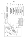
- FIG. 1 is a diagram showing the overall configuration of a particle beam therapy system according to an embodiment of the present disclosure
- FIG. 4 is a flowchart for explaining an example of patient positioning processing
- FIG. 10 is a diagram for explaining processing for obtaining a correction axis from a two-dimensional movement amount
- FIG. 10 is a diagram for explaining processing for obtaining a three-dimensional movement amount from a correction axis
- 5 is an enlarged view of the common perpendicular shown in FIG. 4;
- FIG. 4 is a flowchart for explaining an example of patient positioning processing
- FIG. 10 is a diagram for explaining processing for obtaining a correction axis from a two-dimensional movement amount
- FIG. 1 is a diagram showing the overall configuration of a particle beam therapy system according to one embodiment of the present disclosure.
- a particle beam therapy system A shown in FIG. 1 is a radiotherapy apparatus having a device group for irradiating a particle beam to a patient B who is a subject.
- the particle beam therapy system A includes an accelerator 1, a beam transport device 2, a gantry 3, an irradiation nozzle 4, FPDs 5A and 5B, X-ray tubes 6A and 6B, a bed 7, a robot arm 8, and a communication device. 9 , a data server 10 , a treatment planning device 11 , a fluoroscopic X-ray imaging device 12 , a bed control device 13 and a patient positioning device 20 .
- the accelerator 1 is a particle beam generator that generates a particle beam to irradiate patient B, and accelerates the particle beam until it reaches an energy suitable for treating patient B and outputs it.
- a beam transport device 2 transports the particle beam output from the accelerator 1 to the gantry 3 .
- the type of particle beam is not particularly limited, and examples thereof include proton beams and carbon beams.
- the gantry 3 and the irradiation nozzle 4 are irradiation devices that irradiate the patient B with the particle beam transported from the accelerator 1.
- Gantry 3 adjusts the irradiation angle at which patient B is irradiated with the particle beam transported from accelerator 1 .
- the gantry 3 has a rotating mechanism capable of rotating 360 degrees around the patient B, and adjusts the irradiation angle by rotating.
- the irradiation nozzle 4 is provided on the gantry 3 and irradiates the patient B with the particle beam transported to the gantry 3 .
- the irradiation nozzle 4 may incorporate a mechanism for adjusting the shape of the particle beam to match the shape of the affected area of the patient.
- the FPDs 5A and 5B and the X-ray tubes 6A and 6B constitute an imaging system for fluoroscopic imaging of the patient B.
- the FPDs 5A and 5B are flat panel detectors that image the patient B by detecting X-rays, which are light for imaging, on their detection surfaces.
- the X-ray tubes 6A and 6B are light sources that output X-rays.
- the FPD 5A and the X-ray tube 6A are arranged facing each other so that the X-rays output from the X-ray tube 6A are detected by the FPD 5A through the patient B, and the FPD 5B and the X-ray tube 6B are arranged opposite to each other so that the X-rays output from are transmitted through the patient B and detected by the FPD 5B.
- An axis connecting the center of the FPD 5A and the X-ray tube 6A and an axis connecting the center of the FPD 5B and the X-ray tube 6B are two imaging axes for imaging the patient B.
- the two imaging axes are preferably orthogonal to each other, but need not be orthogonal to each other.
- the particle beam therapy system A may include three or more FPDs and three or more X-ray tubes. In this case, there are three or more imaging axes.
- the bed 7 is a table on which the patient B is placed when the patient B is irradiated with the particle beam.
- a robot arm 8 is a device for moving the bed 7 . Specifically, the robot arm 8 translates the bed 7 in a plurality of translational directions along each of a plurality of movement axes and rotates in a plurality of rotational directions about a plurality of rotational axes. Move and do.
- the movement axis and the rotation axis are the same, and there are three movement axes (rotation axes).
- each movement axis is in the direction from right to left (RL direction) when viewed from the patient B lying face up on the bed 7, the direction from the feet to the head of the patient B (SI direction), and the direction from the back to the abdomen. (AP direction).
- the communication device 9 communicably connects the data server 10, the treatment planning device 11 and the patient positioning device 20 to each other.
- the data server 10 is a storage device that stores various information related to particle beam therapy for patient B.
- the data server 10 stores, for example, a three-dimensional fluoroscopic image of the patient B and treatment plan information indicating a treatment plan for the patient B.
- the 3D fluoroscopic image contains information that describes the shape and electron density of the patient in voxels.
- the three-dimensional fluoroscopic image is, for example, a computed tomography (CT) image, and is generated in advance (before creating treatment plan information for patient B).
- Treatment plan information is generated based on the three-dimensional fluoroscopic image.
- the treatment plan information also includes planned arrangement information indicating planned arrangement, which is the arrangement of the patient B during treatment.
- the placement of the patient B indicates the position and angle (orientation) of the patient B, and is determined by the position and angle of the bed 7 .
- the treatment planning device 11 creates a treatment plan for the patient B based on the three-dimensional fluoroscopic image stored in the data server 10, and stores treatment plan information indicating the treatment plan in the data server 10.
- the fluoroscopic X-ray imaging apparatus 12 controls the FPD 5A and the X-ray tube 6A, and the FPD 5B and the X-ray tube 6B, respectively, and acquires a plurality of fluoroscopic X-ray images of the patient B photographed from different angles as fluoroscopic images. and transmits the acquired fluoroscopic X-ray image to the patient positioning device 20 .
- the bed control device 13 adjusts the placement of the patient B by controlling the robot arm 8 to adjust the placement of the bed 7 .
- the patient positioning device 20 positions the patient B based on the three-dimensional fluoroscopic image and treatment plan information stored in the data server 10 and the fluoroscopic X-ray image acquired by the fluoroscopic X-ray imaging device 12. Execute.
- the patient B positioning process is a process of placing the patient B placed on the bed 7 in the same position as the planned position shown in the treatment plan information before starting particle beam therapy for the patient B.
- the patient positioning device 20 controls the robot arm 8 via the bed control device 13 to adjust the position and angle of the bed 7, thereby placing the patient B in the same placement as the planned placement.
- particle beam therapy will actually be performed on patient B.
- a particle beam accelerated by an accelerator 1 to an energy suitable for treatment is transported to a gantry 3 via a beam transporter 2 .
- the particle beam is deflected in an appropriate direction by the gantry 3, passes through the irradiation nozzle 4, and is irradiated to the patient B's affected area.
- the patient positioning device 20 will be described in more detail below.
- the patient positioning apparatus 20 includes an image acquisition unit 21, a pseudo-fluoroscopic X-ray image generation unit 22, an ROI drawing unit 23, an image matching unit 24, an image display unit 25, and a control unit 26. and
- the image acquisition unit 21 acquires a three-dimensional fluoroscopic image from the data server 10 via the communication device 9 and acquires a fluoroscopic X-ray image from the fluoroscopic X-ray imaging device 12 .
- the pseudo-fluoroscopic X-ray image creating unit 22 projects the three-dimensional fluoroscopic images acquired by the image acquiring unit 21 onto a plurality of planes corresponding to the respective imaging axes for capturing the fluoroscopic X-ray images, forming a plurality of pseudo-fluoroscopic images.
- a creation unit that creates a plurality of pseudo-fluoroscopic X-ray images, which are images.
- the pseudo-fluoroscopic X-ray image creating unit 22 creates a pseudo-fluoroscopic X-ray image by arranging and projecting the three-dimensional image of the patient B in the same virtual space as the imaging system that generated the fluoroscopic X-ray image. .
- the plane corresponding to the imaging axis is, for example, the detection plane of the FPD corresponding to the imaging axis, that is, the plane substantially perpendicular to the imaging axis.
- the ROI drawing unit 23 identifies the ROI, which is the region of interest used for patient positioning in the pseudo-fluoroscopic X-ray image. Specifically, the ROI drawing unit 23 specifies the ROI by displaying the pseudo-fluoroscopic X-ray image and allowing the user to draw the ROI on the pseudo-fluoroscopic X-ray image.
- the ROI is drawn to include the structure to be positioned, eg bone.
- the image matching unit 24 is a calculation processing unit that calculates the bed movement amount for moving the bed 7 based on the fluoroscopic X-ray image and the pseudo-fluoroscopic X-ray image.
- the image matching unit 24 may calculate the bed movement amount based on the fluoroscopic X-ray image and the pseudo-fluoroscopic X-ray image in the ROI.
- the bed movement amount includes movement amounts in each of a plurality of translational directions.
- the image display unit 25 is a display unit that displays various information and images.
- the image display unit 25 displays a fluoroscopic X-ray image, a pseudo-fluoroscopic X-ray image, an ROI image indicating an ROI area, and the like.
- the control unit 26 adjusts the placement of the patient B by controlling the bed control device 13 and moving the bed 7 based on the bed movement amount calculated by the image matching unit 24 .
- the patient positioning device 20 having the above functions can be realized by an information processing device capable of various information processing such as a computer device.
- An information processing device has, for example, an arithmetic element, a storage medium, and a communication interface, and, if necessary, an input unit such as a mouse and a keyboard, and a display unit such as a display.
- Arithmetic elements are, for example, processors such as CPUs (Central Processing Units) and FPGAs (Field-Programmable Gate Arrays).
- Storage media include, for example, magnetic storage media such as HDDs (Hard Disk Drives), semiconductor storage media such as RAMs (Random Access Memory), ROMs (Read Only Memory) and SSDs (Solid State Drives).
- magnetic storage media such as HDDs (Hard Disk Drives), semiconductor storage media such as RAMs (Random Access Memory), ROMs (Read Only Memory) and SSDs (Solid State Drives).
- RAMs Random Access Memory
- ROMs Read Only Memory
- SSDs Solid State Drives
- a combination of an optical disc such as a DVD (Digital Versatile Disk) and an optical disc drive may be used.
- other high cost storage media such as magnetic tape media may be used as storage media.
- Programs such as firmware are stored in the storage medium.
- the arithmetic element reads out the program from the storage medium and executes it, thereby implementing the units 21 to 27 of the patient positioning device 20 and performing the entire series of controls. executed.
- the storage medium stores data required for each process of the patient positioning device 20 and the like.
- the patient positioning device 20 of this embodiment may be configured by so-called cloud computing, in which a plurality of information processing devices are configured to be able to communicate via a communication network.
- FIG. 1 The patient positioning processing by the patient positioning device 20 will be described in more detail below using FIGS. 2 to 5.
- FIG. 1 is a diagrammatic representation of the patient positioning device 20.
- FIG. 2 is a flowchart for explaining an example of patient positioning processing.
- a set-up position is a position for placing the patient B in the same arrangement as the planned arrangement.
- the position of the body surface of the patient B on the bed 7 is measured using an infrared laser installed in the treatment room, and the patient B is placed in the set-up position on the bed 7 based on the position.
- the control unit 26 first acquires treatment plan information from the data server 10, and controls the robot arm 8 via the bed control device 13 based on the planned arrangement information included in the treatment plan information. Then, the bed 7 on which the patient B is placed is moved so that the placement of the patient B becomes the planned placement indicated by the planned placement information (step S100). At this time, the positioning target structure of the patient B placed on the bed 7 is included in the X-ray irradiation area formed by the FPDs 5A and 5B and the X-ray tubes 6A and 6B.
- the image acquiring unit 21 acquires a plurality of fluoroscopic X-ray images obtained by imaging the patient B from a plurality of mutually different directions via the fluoroscopic X-ray imaging device 12 (step S101).
- the image acquisition unit 21 acquires two fluoroscopic X-ray images taken from two directions along two imaging axes.
- the pseudo-fluoroscopic X-ray image creating unit 22 acquires a three-dimensional fluoroscopic image from the data server 10, and creates two pseudo-fluoroscopic X-ray images corresponding to the two imaging axes from the three-dimensional fluoroscopic image (step S102).
- the image matching unit 24 calculates the amount of deviation in the two-dimensional direction between the fluoroscopic X-ray image and the pseudo-fluoroscopic X-ray image corresponding to the imaging axis, on the detection plane of the FPD corresponding to the imaging axis. It is calculated as a movement amount (step S103).
- a calculation method for calculating the amount of image deviation is a method of scanning a pseudo-fluoroscopic X-ray image in the horizontal and vertical directions with respect to the fluoroscopic X-ray image and searching for the position where the similarity between these images is the highest.
- this method requires sequential calculation of the similarity, resulting in a large amount of calculation. Therefore, in this embodiment, a calculation method using a POC (Phase-Only Correlation method) method, which is known as a method capable of high-speed image matching, will be described.
- POC Phase-Only Correlation method
- the POC method is a method of matching (aligning) images using only the phase components obtained from the two-dimensional discrete Fourier transform of the images, and is characterized by being resistant to disturbances such as changes in image brightness.
- the POC method is different from the method of performing matching based on image feature points such as edges and corners, and can perform accurate alignment even for images that do not have clear features.
- the image matching unit 24 uses a POC function (phase-only correlation function) used as an evaluation index for matching by the POC method to determine the amount of deviation between the fluoroscopic X-ray image and the pseudo-fluoroscopic X-ray image. A two-dimensional movement amount is calculated.
- POC function phase-only correlation function
- Images f(n 1 , n 2 ) and g(n 1 , n 2 ) are both N 1 ⁇ N 2 pixel images.
- a two-dimensional discrete Fourier transform (DFT) of images f(n 1 , n 2 ) and g(n 1 , n 2 ) is represented by the following equations (1) and (2).
- a F (k 1 , k 2 ) and AG (k 1 , k 2 ) are amplitude spectra
- ⁇ F (k 1 , k 2 ) and ⁇ G (k 1 , k 2 ) are phase spectra.
- the normalized mutual power spectra of the images f(n 1 ,n 2 ) and g(n 1 ,n 2 ) are the functions F(k 1 ,k 2 ) and G(k 1 ,k 2 ) after the Fourier transform. ), it is represented by the following equation (3). here, denotes the complex conjugate of G(k 1 ,k 2 ). Also, ⁇ F (k 1 , k 2 ) ⁇ G (k 1 , k 2 ) ⁇ is the phase difference spectrum of images f(n 1 , n 2 ) and g(n 1 , n 2 ).
- the POC function r(n 1 , n 2 ) is defined by the following equation (4) as a two-dimensional Inverse Discrete Fourier Transform (IDFT) of the normalized mutual power spectrum.
- IDFT Inverse Discrete Fourier Transform
- the POC function has a sharp peak, called a correlation peak, when the images of interest f(n 1 ,n 2 ) and g(n 1 ,n 2 ) are similar to each other.
- the height of the correlation peak represents the linearity of the phase difference spectra of the images f(n 1 , n 2 ) and g(n 1 , n 2 ) with respect to frequency.
- the correlation peak has a height of 1.
- the height of the correlation peak is useful as a measure of image similarity, and is used in image matching and the like.
- the coordinates of the correlation peak represent the relative displacement amount of the images.
- the image collating unit 24 uses a fluoroscopic X-ray image and a pseudo-fluoroscopic X-ray image as images f(n 1 , n 2 ) and g(n 1 , n 2 ).
- a two-dimensional movement amount is calculated using an image obtained by multiplying an image by a window function.
- the window function is, for example, a two-dimensional Hanning window w(n 1 , n 2 ) represented by Equation (5).
- the image matching unit 24 uses the POC method as described above to determine, for each imaging axis, the position of the correlation peak of the phase-only correlation function calculated from the fluoroscopic X-ray image and the pseudo-fluoroscopic X-ray image, and the origin.
- a shift amount in a dimension direction is calculated as a two-dimensional movement amount.
- the image matching unit 24 executes a three-dimensional movement amount calculation process for calculating a three-dimensional movement amount as a bed movement amount for moving the bed 7 based on the two-dimensional movement amount of each imaging axis (step S104).
- the image matching unit 24 first calculates, for each imaging axis, based on the two-dimensional movement amount, which is the amount of deviation between the fluoroscopic X-ray image and the pseudo-fluoroscopic X-ray image corresponding to the imaging axis. , to obtain a corrected axis obtained by correcting the photographing axis. Then, the image matching unit 24 calculates the movement amount from the intersection of each imaging axis to the midpoint of the common perpendicular line of each correction axis as the three-dimensional movement amount, which is the bed movement amount.
- FIG. 3 to 5 are diagrams for explaining the three-dimensional movement amount calculation process in more detail.
- FIG. 3 is a diagram for explaining the process of obtaining the correction axis from the two-dimensional movement amount
- FIG. 4 is a diagram for explaining the process of obtaining the three-dimensional movement amount from the correction axis.
- 5 is an enlarged view of the common perpendicular shown in FIG. 4; FIG. It is assumed that the distortion of the fluoroscopic X-ray image due to the arrangement angles of the FPDs 5A and 5B has been removed in advance by distortion correction. Distortion correction may be performed, for example, by an imaging device that captures a fluoroscopic X-ray image, or may be performed by the patient positioning device 20 . Further, even if distortion correction is not performed, it is possible to perform the following three-dimensional movement amount calculation processing.
- the center point of the detection surface 5A1 of the FPD 5A is OA
- the center point of the detection surface 5B1 of the FPD 5B is OB
- the imaging axis is a line L 1 connecting the center point OA of the detection surface 5A1 and the X-ray tube 6A, and a line L 2 connecting the center point OB of the detection surface 5B1 and the X-ray tube 6B.
- the image matching unit 24 sets the intersection of the imaging axes L1 and L2 as a reference position IC (the origin of the coordinate system), and places the reference position IC on the detection surface 5A1 of the FPD 5A by a two-dimensional movement amount corresponding to the imaging axis L1 .
- l 2 and are the correction axes.
- the position of the X-ray tube 6A is A( xa , ya , za ), and the position of the matched center point on the detection surface 5A1 of the FPD 5A is B( xb , yb , z b ), the position of the X-ray tube 6B is C(x c , y c , z c ), and the position of the matched center point on the detection surface 5B1 of the FPD 5B is D(x d , y d , z d ).
- the coordinates of each position A to D are three-dimensional coordinates in a coordinate system (X, Y, Z) preset in the treatment room where the gantry 3 and the bed 7 are arranged, and the reference position IC is the origin of the coordinate system.
- the matched center points are the intersections of the correction axes l1 and l2 and the detection surfaces 5A1 and 5B1.
- the lines l1 and l2 which are the correction axes, ideally intersect each other, but in practice there is a small error in the position of the matched center point depending on the image resolution, FPDs 5A and 5B and X-ray tubes 6A and 6B. They may not intersect each other due to a slight deviation in mechanical arrangement.
- the image matching unit 24 determines points P and Q on the lines l1 and l2 where the distance between the lines l1 and l2 is the smallest. , and the position of the middle point of the line segment l3 connecting the points P and Q is calculated in three-dimensional coordinates.
- Line l3 is a common perpendicular perpendicular to both lines l1 and l2 , which are in a twisted relationship with each other.
- the length of line l3 will be referred to as the common perpendicular length.
- the points P and Q are the legs of the common perpendicular l3 .
- p is the position vector of point P (x p , y p , z p )
- q is the position vector of point Q (x q , y q , z q )
- a is the position vector of point A (x a , y a , z a )
- c is the position vector of point C (x c , y c , z c )
- u is the direction vector of line l 1
- v is the direction vector of line l 2 .
- the values of the parameters s and t can be obtained.
- (
- ⁇ 2p ⁇ q) 1/2 ⁇ (x q ⁇ x p ) 2 +(y q ⁇ y p ) 2 +(z q ⁇ z p ) 2 ⁇ 1/2 .
- the three-dimensional movement amount is the amount of movement from the intersection point of each imaging axis to the midpoint M of the line segment PQ.
- the value of the coordinates of the point M can be calculated as the three-dimensional movement amount, which is the movement amount of the bed.
- the image matching unit 24 calculates the three-dimensional movement amount and the common perpendicular length according to the above method. Note that when the lines l1 and l2 that are the correction axes intersect each other, the image matching unit 24 regards the intersection point of the lines l1 and l2 as the midpoint M of the line segment PQ, and calculates the three-dimensional movement amount. .
- the image matching section 24 determines whether the common perpendicular line length is less than a threshold value (for example, 1 mm) (step S105).
- a threshold value for example, 1 mm
- the common perpendicular length is ideally zero, ie the lines l 1 and l 2 intersect each other. The longer the common perpendicular length, the less consistent the two-dimensional movement amount and the three-dimensional movement amount of the pseudo-fluoroscopic X-ray image and the fluoroscopic X-ray image.
- the image matching unit 24 may determine whether or not the correlation peak of the POC function is less than the threshold instead of the common perpendicular length.
- step S105 If the common perpendicular length is equal to or greater than the threshold (step S105: No), the image matching unit 24 changes at least one of the fluoroscopic X-ray image and the pseudo-fluoroscopic X-ray image (step S106), and returns to the process of step S102. .
- An image is changed, for example, by executing predetermined image processing on an image to be changed, which is at least one of a fluoroscopic X-ray image and a pseudo-fluoroscopic X-ray image.
- Predetermined image processing includes, for example, filtering processing for emphasizing edges of the image to be changed, processing for extracting a specific partial image from the image to be changed, and the like.
- the partial image is, for example, an image representing the ROI, and may be executed by the ROI drawing section 23 . Also, when the processing of steps S103 and S104 is first executed, an image showing the ROI extracted from the fluoroscopic X-ray image and the pseudo-fluoroscopic X-ray image may be used.
- the image modification may be performed by returning the partial image showing the ROI to the original fluoroscopic X-ray image and pseudo-fluoroscopic X-ray image.
- the image is changed by acquiring another fluoroscopic X-ray image from the fluoroscopic X-ray imaging device 12 or creating another pseudo-fluoroscopic X-ray image from another three-dimensional fluoroscopic image. good too.
- step S105 if the common perpendicular length is less than the threshold (step S105: Yes), the control unit 26 moves the bed 7 via the bed control device 13 based on the three-dimensional movement amount calculated by the image matching unit 24. (step S107), and the patient positioning process ends. This allows the patient to be moved from the current configuration to the configuration at the time of treatment planning, after which the actual particle beam irradiation is performed.
- the image matching unit 24 calculates the similarity between each corrected pseudo fluoroscopic image obtained by correcting the pseudo fluoroscopic X-ray image based on the bed movement amount and each fluoroscopic image.
- a fine adjustment process for calculating the amount of translation and the amount of rotation of the bed 7 may be performed by optimization calculation.
- the control unit 26 moves the bed 7 via the bed control device 13 based on the three-dimensional movement amount calculated by the image matching unit 24 and the translation amount and rotation amount calculated in the fine adjustment process. .
- control unit 26 moves the bed 7 by the three-dimensional movement amount, and then translates and rotates the bed 7 by the translation amount and rotation amount calculated in the fine adjustment process.
- the amount of translation is calculated with respect to each of the plurality of movement axes of the bed 7
- the amount of rotation is calculated with respect to each of the plurality of rotation axes of the bed 7 .
- the image matching unit 24 may perform the processes described in Patent Documents 1 to 3, for example. Further, based on the similarity, the image matching unit 24 selects a plurality of translation directions along each of a plurality of optimization axes including a plurality of imaging axes and a plurality of rotation directions about a plurality of rotation axes. , a process of calculating the amount of movement of the bed 7 that best matches each fluoroscopic image and each pseudo fluoroscopic image may be performed.
- a particle beam therapy system is exemplified as a radiation therapy device, but the radiation therapy device is not limited to a particle beam therapy system, and may be a radiation therapy system using non-particle beams such as X-rays.
- the accelerator 1 is, for example, an electron beam accelerator that outputs X-rays.
- the image acquisition unit 21 acquires a plurality of fluoroscopic X-ray images of the subject.
- the pseudo-fluoroscopic X-ray image creating unit 22 creates a pseudo-fluoroscopic image by projecting a three-dimensional fluoroscopic image of the subject onto a detection plane for each imaging axis of the fluoroscopic X-ray image.
- the image matching unit 24 corrects the imaging axis based on the two-dimensional movement amount, which is the amount of deviation between the fluoroscopic X-ray image and the pseudo-fluoroscopic X-ray image corresponding to the imaging axis.
- the image matching unit 24 obtains, for each of a plurality of imaging axes, the axis connecting the X-ray tube and the position obtained by moving the intersection of the imaging axes by the two-dimensional movement amount as the correction axis.
- the image matching unit 24 since it is possible to calculate an appropriate correction axis according to the deviation between the fluoroscopic X-ray image and the pseudo-fluoroscopic X-ray image, it is possible to perform positioning with higher accuracy.
- the image matching unit 24 calculates the two-dimensional movement amount based on the peak position of the phase-only correlation function calculated from the fluoroscopic X-ray image and the pseudo-fluoroscopic X-ray image. In this case, since the two-dimensional movement amount can be calculated without performing sequential calculation such as optimization calculation, it is possible to further reduce the calculation time.
- the image matching unit 24 calculates a phase-only correlation function from ROIs set on the fluoroscopic X-ray image and the pseudo-fluoroscopic X-ray image. Therefore, it is possible to more appropriately calculate the two-dimensional movement amount.
- the image matching unit 24 changes at least one of the fluoroscopic X-ray image and the pseudo-fluoroscopic X-ray image, and resets the correction axis. demand.
- the image matching unit 24 since it is possible to obtain a correction axis in which the two-dimensional movement amount and the three-dimensional movement amount of the pseudo-fluoroscopic X-ray image and the fluoroscopic X-ray image are more matched, more accurate positioning becomes possible.
- the image is changed by performing predetermined image processing. Therefore, there is no need to re-capture a fluoroscopic X-ray image or recreate a pseudo-fluoroscopic X-ray image from a three-dimensional fluoroscopic image, so that the calculation time can be further reduced.
- the image matching unit 24 determines the translational direction of the bed 7 based on the degree of similarity between each corrected pseudo-fluoroscopic image obtained by correcting each pseudo-fluoroscopic X-ray image based on the amount of movement of the bed and each fluoroscopic image. And the amount of movement in the rotational direction is further calculated. In this case, positioning with better accuracy becomes possible. Even in this case, since each pseudo-fluoroscopy image is corrected based on the amount of bed movement, it is possible to suppress the patient's position from deviating greatly from the planned position at the start of fine adjustment. increase can be suppressed. Therefore, it is possible to further reduce the calculation time.
- A... Particle beam therapy system B... Patient, 1... Accelerator, 2... Beam transporter, 3... Gantry, 4... Irradiation nozzle, 5A... FPD, 5B... FPD, 6A... X-ray tube, 6B... X-ray tube, 7... Bed 8... Robot arm 9... Communication device patient 10... Data server 11... Treatment planning device 12... Fluoroscopic X-ray imaging device 13... Bed control device 20... Patient positioning device 21... Pseudo Fluorescent X-ray image creating unit 23 ROI drawing unit 24 image matching unit 25 image display unit 26 control unit
Abstract
計算時間を低減しながら精度の高い患者位置決めを可能とする位置決め装置、放射線治療装置及び位置決め方法を提供する。画像取得部21は、被検者を撮影した複数の透視X線画像を取得する。疑似透視X線画像作成部22は、透視X線画像の撮影軸のそれぞれについて、被検者の3次元透視画像を当該撮影軸に対する検出面に投影した疑似透視画像を作成する。画像照合部24は、複数の撮影軸のそれぞれについて、その撮影軸に応じた透視X線画像と疑似透視X線画像とのズレ量である2次元移動量に基づいて撮影軸を補正した補正軸を求め、各撮影軸の交点から各補正軸の共通垂線における中点までの移動量を、寝台を移動させる寝台移動量として算出する。
Description
本開示は、位置決め装置、放射線治療装置及び位置決め方法に関する。
がんの治療法の1つとして、放射線を患者に照射する放射線治療が知られている。放射線治療で用いられる放射線は、X線又はガンマ線のような非荷電粒子線と、陽子線又は炭素線のような荷電粒子線とに大別される。後者の荷電粒子線を使用した放射線治療は、一般に粒子線治療と呼ばれている。
非荷電粒子線の場合、線量は体内で浅い位置から深い位置にかけて一定の割合で減少する。一方、荷電粒子線の場合、特定の深さにエネルギー損失のピークを有する線量分布(ブラックカーブ)を形成することができる。このため、荷電粒子線のエネルギー損失のピークを腫瘍の位置に合わせることにより、腫瘍よりも深い位置にある正常な組織へ照射される荷電粒子線の線量を大幅に低下させることが可能となる。
このため、放射線治療では、所望の線量の放射線を正確に標的となる腫瘍に照射することが治療効果の向上にとって重要である。放射線の腫瘍への正確な照射を実現するためには、予め作成した治療計画によって決められた計画位置と同じ位置に患者の位置を合わせる必要がある。この患者の位置を合わせることを患者の位置決めと呼ぶ。
放射線治療における患者の位置決めの方法として、寝台の上に寝ている患者を、2組のX線管と平面検出器(Flat Panel Detector:FPD)により互いに異なる2方向から撮影した透視X線画像(Digital Radiography:DR)を用いる方法がある。この方法では、放射線治療時に患者を撮影した透視X線画像と、治療計画を作成する際に用いたCT(Computed Tomography)画像から作成した疑似透視X線画像とを比較して、骨のような位置決め対象構造物の位置が透視X線画像と疑似透視X線画像とで一致するように患者の位置決めが行われる。
また、一般的に、透視X線画像には患者の固定具及び軟組織のような位置決め対象構造物以外の構造物が写り込んだり、位置決め対象構造物である骨の配置が治療計画時から変化したりすることがある。このような状況では、透視X線画像と疑似透視X線画像とに写された構造が画像全体にわたって一致しない。この場合、透視X線画像上で位置決め対象構造物が存在する領域として設定された関心領域(Region of Interest:ROI)を用いた患者の位置決めが行われる。なお、関心領域の設定は、通常、医療従事者であるユーザが画像上に関心領域を描画することで行われる。
患者の位置決めを行う自動位置合わせは、患者が寝ている寝台の並進量及び回転量をパラメータとし、そのパラメータの最適値を最適化計算により算出することで行われる。通常、並進量は、互いに直交する3軸(x、y、z)に沿った3成分を有し、回転量は、その3軸を回転軸とした3成分(Pitch、Roll、Yaw)を有するため、最適化計算では、6成分のそれぞれに対する最適化プロセスが繰り返し行われることで、パラメータの最適値が算出される。また、並進量を規定する3軸は、患者を計画位置に配置するための寝台の移動軸と一致し、x軸は仰向けに寝台に横たわった患者から見て右から左に向かう方向(Right-Left direction:RL方向)、y軸は足から頭に向かう方向(Superior-Inferior direction:SI方向)、z軸は背中から腹部に向かう方向(Anterior-Posterior:AP方向)を向いている。
しかしながら、位置決め開始時の患者の位置が計画位置から大きく離れている場合、最適化計算において、その判断指標となる画像間の類似度の変化が小さくなり、最適な位置に向かって類似度が高くなるような特徴を利用することができず、パラメータの最適値に到達できなかったり、最適化計算における繰り返し計算回数の増加により計算時間が増加したりすることがある。
これに対して、特許文献1及び2には、最適値により少ない繰り返し計算回数で到達するための技術が開示されている。これらの技術では、最適化計算において、各成分に対する最適化プロセスが終了した後で透視X線画像を撮影する撮影軸に沿った方向に対する1次元方向の最適化プロセスを追加することで、最適化計算における最適化プロセスを繰り返す計算回数の軽減化が図られている。
また、特許文献3には、撮影軸に沿った方向に対する並進量の最適化を、その透視撮影軸に直交する1方向によってのみ評価することで、透視X線画像の枚数を削減して、患者の位置決めに係る時間の短縮化を図る技術が開示されている。
しかしながら、特許文献1~3に記載の技術では、画像の類似度を用いた最適化を行っていることには変わりがないため、位置決め開始時の患者の位置が計画位置から大きく離れ、画像間の類似度の変化が小さくなる場合などでは、最適化計算における繰り返し計算回数の増加により計算時間が増加することを抑制できないことがある。
本開示の目的は、計算時間をより低減することが可能な位置決め装置、放射線治療装置及び位置決め方法を提供することにある。
本開示の一態様に従う位置決め装置は、被検者が搭載される寝台の位置を制御する位置決め装置であって、複数の撮影軸のそれぞれについて光源からの光を前記被検者を介して検出面で検出することで前記被検者を撮影した複数の透視画像を取得する画像取得部と、
前記複数の撮影軸のそれぞれについて、前記被検者の3次元透視画像を当該撮影軸に対する検出面に投影した疑似透視画像を作成する作成部と、前記複数の撮影軸のそれぞれについて、当該撮影軸に応じた前記透視画像と前記疑似透視画像とのズレ量に基づいて当該撮影軸を補正した補正軸を求め、前記複数の撮影軸の交点から各補正軸の共通垂線における中点までの移動量を、前記寝台を移動させる寝台移動量として算出する計算処理部と、を有する。
前記複数の撮影軸のそれぞれについて、前記被検者の3次元透視画像を当該撮影軸に対する検出面に投影した疑似透視画像を作成する作成部と、前記複数の撮影軸のそれぞれについて、当該撮影軸に応じた前記透視画像と前記疑似透視画像とのズレ量に基づいて当該撮影軸を補正した補正軸を求め、前記複数の撮影軸の交点から各補正軸の共通垂線における中点までの移動量を、前記寝台を移動させる寝台移動量として算出する計算処理部と、を有する。
本発明によれば、計算時間をより低減することが可能になる。
以下、本開示の実施形態について図面を参照して説明する。
なお、以下の記載及び図面は、本発明を説明するための例示であって、説明の明確化のため、適宜、省略及び簡略化がなされている。本発明は、他の種々の形態でも実施することが可能である。特に限定しない限り、各構成要素は単数でも複数でもよい。また、実施形態を説明する図において、同一の機能を有する箇所には同一の符号を付し、その繰り返しの説明は省略することがある。また、図面において示す各構成要素の位置、大きさ、形状、範囲などは、発明の理解を容易にするため、実際の位置、大きさ、形状、範囲などを表していない場合がある。このため、本発明は、図面に開示された位置、大きさ、形状、範囲などに限定されない。また、同一あるいは同様の構成要素が複数ある場合には、同一の符号に異なる添字を付して説明する場合がある。ただし、これらの複数の構成要素を区別する必要がない場合には、添字を省略して説明する場合がある。
図1は、本開示の一実施形態に係る粒子線治療システムの全体構成を示す図である。図1に示す粒子線治療システムAは、被検者である患者Bを標的として粒子線を照射するための装置群を有する放射線治療装置である。粒子線治療システムAは、加速器1と、ビーム輸送装置2と、ガントリ3と、照射ノズル4と、FPD5A及び5Bと、X線管6A及び6Bと、寝台7と、ロボットアーム8と、通信装置9と、データサーバ10と、治療計画装置11と、透視X線画像撮影装置12と、寝台制御装置13と、患者位置決め装置20とを備える。
加速器1は、患者Bに照射する粒子線を生成する粒子線生成器であり、粒子線を、患者Bの治療に適したエネルギーになるまで加速して出力する。ビーム輸送装置2は、加速器1から出力された粒子線をガントリ3まで輸送する。粒子線の種類は、特に限定されず、例えば、陽子線又は炭素線などである。
ガントリ3及び照射ノズル4は、加速器1から輸送された粒子線を患者Bに照射する照射装置である。ガントリ3は、加速器1から輸送された粒子線を患者Bに照射する照射角度を調整する。具体的には、ガントリ3は、患者Bを囲って360°の回転することが可能な回転機構を有し、回転することにより照射角度を調整する。照射ノズル4は、ガントリ3に備わっており、ガントリ3まで輸送された粒子線を患者Bに照射する。照射ノズル4には、粒子線の形状を患者の患部の形状に合うように調整する機構が組み込まれていてもよい。
FPD5A及び5BとX線管6A及び6Bとは、患者Bの透視撮影を行う撮影体系を構成する。FPD5A及び5Bは、撮影用の光であるX線を検出面で検出することで患者Bを撮影する平面検出器である。X線管6A及び6Bは、X線を出力する光源である。FPD5A及びX線管6Aは、X線管6Aから出力されたX線が患者Bを介してFPD5Aにて検出されるように対向して配置され、FPD5B及びX線管6Bは、X線管6Bから出力されたX線が患者Bを介してFPD5Bにて検出されるように対向して配置される。FPD5Aの中心とX線管6Aとを結ぶ軸と、FPD5Bの中心とX線管6Bとを結ぶ軸とが患者Bを撮影する2つの撮影軸となる。2つの撮影軸は、互いに直交することが好ましいが、互いに直交していなくてもよい。また、粒子線治療システムAは、FPD及びX線管をそれぞれ3つ以上備えてもよい。この場合、撮影軸も3つ以上となる。
寝台7は、患者Bに粒子線を照射する際に患者Bを載せる台である。ロボットアーム8は、寝台7を移動させる装置である。具体的には、ロボットアーム8は、寝台7に対して、複数の移動軸のそれぞれに沿った複数の並進方向への並進移動と、複数の回転軸を中心とした複数の回転方向への回転移動とを行う。本実施形態では、移動軸と回転軸同一であり、移動軸(回転軸)は3つある。また、各移動軸は、寝台7に仰向けに横たわった患者Bから見て右から左に向かう方向(RL方向)、患者Bの足から頭に向かう方向(SI方向)、背中から腹部に向かう方向(AP方向)を向いている。
通信装置9は、データサーバ10、治療計画装置11及び患者位置決め装置20を互いに通信可能に接続する。
データサーバ10は、患者Bの粒子線治療に関する種々の情報を格納する格納装置である。データサーバ10は、例えば、患者Bの3次元透視画像と、患者Bの治療計画を示す治療計画情報とを格納する。3次元透視画像は、患者の形状及び電子密度をボクセル単位で示す情報を含む。3次元透視画像は、例えば、コンピュータ断層(Computed Tomography:CT)撮影画像であり、事前(患者Bの治療計画情報を作成する前)に生成される。治療計画情報は、3次元透視画像に基づいて生成される。また、治療計画情報は、治療時の患者Bの配置である計画配置を示す計画配置情報を含む。患者Bの配置は、患者Bの位置及び角度(姿勢)を示し、寝台7の位置及び角度によって定まる。
治療計画装置11は、データサーバ10に格納された3次元透視画像に基づいて、患者Bの治療計画を作成し、その治療計画を示す治療計画情報をデータサーバ10に格納する。
透視X線画像撮影装置12は、FPD5A及びX線管6Aと、FPD5B及びX線管6Bとをそれぞれ制御して、患者Bを互いに異なる角度から撮影した複数の透視X線画像を透視画像として取得し、その取得した透視X線画像を患者位置決め装置20に送信する。透視X線画像は、本実施形態では、2つある。
寝台制御装置13は、ロボットアーム8を制御して寝台7の配置を調整することで、患者Bの配置を調整する。
患者位置決め装置20は、データサーバ10に格納された3次元透視画像及び治療計画情報と、透視X線画像撮影装置12にて取得された透視X線画像とに基づいて、患者Bの位置決め処理を実行する。
患者Bの位置決め処理は、患者Bの粒子線治療の開始前に、寝台7に載せられた患者Bを治療計画情報にて示される計画配置と同じ配置にする処理である。患者位置決め装置20は、寝台制御装置13を介してロボットアーム8を制御して寝台7の位置及び角度を調整することで、患者Bを計画配置と同じ配置にする。
位置決め処理が終了すると、実際に患者Bの粒子線治療が行われる。具体的には、加速器1にて治療に適したエネルギーまで加速された粒子線がビーム輸送装置2を介してガントリ3に輸送される。粒子線は、ガントリ3にて適切な方向に偏向され、照射ノズル4を通過して患者Bの患部に照射される。
以下、患者位置決め装置20についてより詳細に説明する。
患者位置決め装置20は、図1に示すように、画像取得部21と、疑似透視X線画像作成部22と、ROI描画部23と、画像照合部24と、画像表示部25と、制御部26とを有する。
画像取得部21は、データサーバ10から通信装置9を介して3次元透視画像を取得し、透視X線画像撮影装置12から透視X線画像を取得する。
疑似透視X線画像作成部22は、画像取得部21にて取得された3次元透視画像を、透視X線画像を撮影する各撮影軸に応じた複数の面のそれぞれに投影した複数の疑似透視画像である複数の疑似透視X線画像を作成する作成部である。疑似透視X線画像作成部22は、透視X線画像を生成した撮影体系と同じ仮想的な空間上で患者Bの3次元画像を配置して投影処理することで疑似透視X線画像を作成する。撮影軸に応じた面は、例えば、撮影軸に対応するFPDの検出面、つまり撮影軸に略直交する面である。
ROI描画部23は、疑似透視X線画像における患者の位置決めに使用する関心領域であるROIを特定する。具体的には、ROI描画部23は、疑似透視X線画像を表示して、ユーザに疑似透視X線画像上にROIを描画させることで、ROIを特定する。ROIは、例えば、骨のような位置決め対象構造物を含むように描画される。
画像照合部24は、透視X線画像と疑似透視X線画像に基づいて、寝台7を移動させる寝台移動量を算出する計算処理部である。ROI描画部23にてROIが指定されている場合、画像照合部24は、ROIにおける透視X線画像と疑似透視X線画像とに基づいて、寝台移動量を算出してもよい。なお、寝台移動量は、本実施形態では、複数の並進方向のそれぞれの移動量を含む。
画像表示部25は、種々の情報及び画像を表示する表示部である。例えば、画像表示部25は、透視X線画像、疑似透視X線画像、及び、ROI領域を示すROI画像などを表示する。
制御部26は、画像照合部24にて算出された寝台移動量に基づいて、寝台制御装置13を制御して、寝台7を移動させることで、患者Bの配置を調整する。
以上の機能を有する患者位置決め装置20は、コンピュータ装置のような種々の情報処理が可能な情報処理装置にて実現することができる。情報処理装置は、例えば、演算素子、記憶媒体及び通信インターフェースを有し、さらに、必要に応じてマウス及びキーボードのような入力部と、ディスプレイのような表示部とを有する。
演算素子は、例えば、CPU(Central Processing Unit)及びFPGA(Field-Programmable Gate Array)などのプロセッサである。記憶媒体は、例えば、HDD(Hard Disk Drive)などの磁気記憶媒体、RAM(Random Access Memory)、ROM(Read Only Memory)及びSSD(Solid State Drive)などの半導体記憶媒体などである。また、記憶媒体として、DVD(Digital Versatile Disk)などの光ディスク及び光ディスクドライブの組み合わせが用いられてもよい。さらに、記憶媒体として、磁気テープメディアのような他の高値の記憶媒体が用いられてもよい。
記憶媒体には、ファームウェアなどのプログラムが格納されている。患者位置決め装置20の動作開始時(例えば電源投入時)に、演算素子がプログラムを記憶媒体から読み出して実行することにより、患者位置決め装置20の各部21~27が実現され、全体の一連の制御が実行される。また、記憶媒体には、プログラム以外にも、患者位置決め装置20の各処理に必要なデータ等が格納される。
なお、本実施形態の患者位置決め装置20は、複数の情報処理装置が通信ネットワークを介して通信可能に構成された、いわゆるクラウドコンピューティングにて構成されてもよい。
以下、患者位置決め装置20による患者位置決め処理について、図2から図5を用いてより詳細に説明する。
図2は、患者位置決め処理の一例を説明するためのフローチャートである。
なお、患者Bは寝台7のセットアップポジションに配置されているものとする。セットアップポジションとは、患者Bを計画配置と同じ配置にするための位置である。例えば、寝台7上の患者Bの体表の位置が治療室内に設置された赤外線レーザを用いて測定され、その位置に基づいて、患者Bが寝台7のセットアップポジションに配置される。
患者位置決め処理では、先ず、制御部26は、データサーバ10から治療計画情報を取得し、その治療計画情報に含まれる計画配置情報に基づいて、寝台制御装置13を介してロボットアーム8を制御して、患者Bの配置が計画配置情報にて示される計画配置となるように、患者Bを載せた寝台7を移動させる(ステップS100)。このとき、寝台7に載せられた患者Bの位置決め対象構造物が、FPD5A及び5BとX線管6A及び6Bとで形成されるX線の照射領域に含まれる。
その後、画像取得部21は、透視X線画像撮影装置12を介して、患者Bを互いに異なる複数の方向から撮影した複数の透視X線画像を取得する(ステップS101)。本実施形態では、画像取得部21は、2つの撮影軸に沿った2つの方向から撮影した2つ透視X線画像を取得する。
疑似透視X線画像作成部22は、データサーバ10から3次元透視画像を取得し、その3次元透視画像から、2つの撮影軸のそれぞれに応じた2つの疑似透視X線画像を作成する(ステップS102)。
画像照合部24は、撮影軸ごとに、その撮影軸に応じた透視X線画像と疑似透視X線画像との2次元方向のズレ量を、撮影軸に応じたFPDの検出面上における2次元移動量として算出する(ステップS103)。
画像のズレ量を算出する算出方法には、疑似透視X線画像を、透視X線画像に対して横方向及び縦方向に走査してそれらの画像の類似度が最も高くなる位置を探索する方法が知られているが、この方法では、類似度の逐次算出が必要であり計算量が多くなる。そこで、本実施形態では、高速な画像照合が可能な手法として知られるPOC(Phase-Only Correlation method:位相限定相関)法を用いた算出方法について説明する。
POC法は、画像に対する2次元離散フーリエ変換から得られる位相成分のみを用いて画像のマッチング(位置合わせ)を行う方法であり、画像の輝度変化などの外乱に強いという特徴を有する。また、POC法は、エッジ又はコーナーのような画像の特徴点に基づいてマッチングを行う方法とは異なり、明確な特徴が存在しない画像に対しても精度良く位置合わせを行うことができる。
本実施形態では、画像照合部24は、POC法によるマッチングの評価指標として使用されるPOC関数(位相限定相関関数)を用いて、透視X線画像と疑似透視X線画像とのズレ量である2次元移動量を算出する。
ここで、POC法による算出方法の対象となる2つの画像を画像f(n1,n2)及びg(n1,n2)とする。画像f(n1,n2)及びg(n1,n2)は、両方ともN1×N2ピクセルの画像である。n1及びn2は、ピクセルを示す離散空間インデックスであり、n1=-M1,…,M1、n2=-M2,…,M2である。なお、n1及びn2は整数であり、M1及びM2は正の整数であり、N1=2M1+1、N1=2M1+1を満たす。
画像f(n1,n2)及びg(n1,n2)の2次元離散フーリエ変換(Discrete Fourier Transform: DFT)は、次の式(1)及び(2)で表される。

 ここで、k1(=-M1,…,M1)及びk2(=-M2,…,M2)は、離散周波数インデックス(整数)であり、WN1=exp(-j・2π/N1)及びWN1=exp(-j・2π/N2)は、回転因子である。AF(k1,k2)及びAG(k1,k2)は、振幅スペクトルであり、θF(k1,k2)及びθG(k1,k2)は、位相スペクトルである。また、総和Σn1,n2は、離散空間インデックスの全域に渡る総和Σn1=-M1
M1Σn2=-M2
M2を示す。
ここで、k1(=-M1,…,M1)及びk2(=-M2,…,M2)は、離散周波数インデックス(整数)であり、WN1=exp(-j・2π/N1)及びWN1=exp(-j・2π/N2)は、回転因子である。AF(k1,k2)及びAG(k1,k2)は、振幅スペクトルであり、θF(k1,k2)及びθG(k1,k2)は、位相スペクトルである。また、総和Σn1,n2は、離散空間インデックスの全域に渡る総和Σn1=-M1
M1Σn2=-M2
M2を示す。
また、画像f(n1,n2)及びg(n1,n2)のの正規化相互パワースペクトルは、フーリエ変換後の関数F(k1,k2)及びG(k1,k2)を用いて、次の式(3)で表される。

ここで、

は、G(k1,k2)の複素共役を示す。また、{θF(k1,k2)-θG(k1,k2)}は、画像f(n1,n2)及びg(n1,n2)の位相差スペクトルである。
POC関数r(n1,n2)は、正規化相互パワースペクトルの2次元逆離散フーリエ変換(Inverse Discrete Fourier Transform:IDFT)として、次の式(4)で定義される。

ここで、総和Σk1,k2は、離散周波数インデックスの全域に渡る総和Σk1=-M1
M1Σk2=-M2
M2を示す。
POC関数は、対象の画像f(n1,n2)及びg(n1,n2)が互いに類似している場合、相関ピークと呼ばれる鋭いピークを有する。相関ピークの高さは、画像f(n1,n2)及びg(n1,n2)の位相差スペクトルの周波数に対する線形性を表しており、位相差スペクトルが周波数に対して線形であれば、相関ピークの高さは1となる。相関ピークの高さは、画像の類似性を表す尺度として有用であり、画像照合などにおいて使用されている。また、相関ピークの座標は、画像の相対的なズレ量を表す。例えば、画像の原点(n1=0,n2=0)に対する相関ピークの座標のズレ量を画像f(n1,n2)及びg(n1,n2)のズレ量として利用することができる。
なお、2次元DFTでは、対象の画像の端部で循環することを仮定しているため、画像端に本来は存在しないはずの不連続性が現れる。本実施形態では、この不連続性を軽減するために、画像照合部24は、画像f(n1,n2)及びg(n1,n2)として、透視X線画像及び疑似透視X線画像に窓関数を乗算した画像を使用して、2次元移動量を算出する。窓関数は、例えば、式(5)で表される2次元ハニング窓(Hanning window)w(n1,n2)である。

画像照合部24は、以上説明したようなPOC法を用いて、撮影軸ごとに、透視X線画像及び疑似透視X線画像から算出される位相限定相関関数の相関ピークの位置と原点との2次元方向のズレ量を2次元移動量として算出する。
図2の説明に戻る。画像照合部24は、各撮影軸の2次元移動量に基づいて、寝台7を移動させる寝台移動量として3次元移動量を算出する3次元移動量算出処理を実行する(ステップS104)。
3次元移動量算出処理では、画像照合部24は、先ず、撮影軸ごとに、その撮影軸に応じた透視X線画像と疑似透視X線画像とのズレ量である2次元移動量に基づいて、撮影軸を補正した補正軸を求める。そして、画像照合部24は、各撮影軸の交点から各補正軸の共通垂線における中点までの移動量を、寝台移動量である3次元移動量として算出する。
図3~図5は、3次元移動量算出処理をより詳細に説明するための図である。具体的には、図3は、2次元移動量から補正軸を求める処理を説明するための図であり、図4は、補正軸から3次元移動量を求める処理を説明するための図であり、図5は、図4に示す共通垂線の拡大図である。なお、FPD5A及び5Bの配置角度などによって透視X線画像の歪みは予め歪み補正により除去されているものとする。歪み補正は、例えば、透視X線画像を撮影する撮影装置で行われてもよいし、患者位置決め装置20で行われてもよい。また、歪み補正が行われていなくても、以下の3次元移動量算出処理を行うことは可能である。
図3に示すように、FPD5Aの検出面5A1の中心点をOA、FPD5Bの検出面5B1の中心点をOBとしている。撮影軸は、検出面5A1の中心点OAとX線管6Aとを結ぶ線L1、検出面5B1の中心点OBとX線管6Bとを結ぶ線L2となる。
画像照合部24は、撮影軸L1及びL2の交点を基準位置IC(座標系の原点)とし、基準位置ICを撮影軸L1に応じた2次元移動量だけFPD5Aの検出面5A1上に沿って移動させた位置とX線管6Aを結ぶ線l1と、撮影軸L2に応じた2次元移動量だけFPD5Bの検出面5B1上に沿って移動させた位置とX線管6Bを結ぶ線l2と、を補正軸とする。
ここで、図4に示すように、X線管6Aの位置をA(xa,ya,za)、FPD5Aの検出面5A1上のマッチングした中心点の位置をB(xb,yb,zb)、X線管6Bの位置をC(xc,yc,zc)、FPD5Bの検出面5B1上のマッチングした中心点の位置をD(xd,yd,zd)とする。各位置A~Dの座標は、ガントリ3及び寝台7が配置された治療室内に予め設定された座標系(X,Y,Z)における3次元座標であり、基準位置ICを座標系の原点としている。また、マッチングした中心点は、補正軸l1及びl2と検出面5A1及び5B1との交点である。
補正軸である線l1及びl2は、理想的には互いに交わるが、実際には、画像解像度に依存したマッチングした中心点の位置の微小誤差、FPD5A及び5BとX線管6A及び6Bと機械配置の微小なずれなどのために、互いに交わらない場合がある。
線l1及び線l2が互いに交わらない場合、画像照合部24は、線l1及び線l2上における、線l1と線l2との距離が最も小さくなる点を点P及び点Qとし、その点Pと点Qとを結ぶ線分l3の中点の位置を3次元座標で算出する。線l3は互いにねじれ関係にある線l1と線l2の両方に垂直な共通垂線である。以下、線l3の長さを共通垂線長と呼ぶ。また、点P及びQは、共通垂線l3の足となる。
線l1の点Pと線l2の点Qは、媒介変数s及びtを用いて以下のようにベクトル表記することができる。
p=a+su
q=c+tv
p=a+su
q=c+tv
ここで、pは点Pの位置ベクトル(xp,yp,zp)、qは点Qの位置ベクトル(xq,yq,zq)、aは点Aの位置ベクトル(xa,ya,za)、cは点Cの位置ベクトル(xc,yc,zc)、uは線l1の方向ベクトル、vは線l2の方向ベクトルである。
線分PQは方向ベクトルu及びvのそれぞれと直交するため、線分PQの方向ベクトルwと方向ベクトルu及びvとの内積はゼロとなる。つまり、w・u=0、w・v=0である。なお、演算子「・」は内積を示す。
この内積の2式を連立一次方程式として解くことで、媒介変数s及びtの値を求めることができる。これにより、点P及びQの座標、並びに、線分PQの長さである共通垂線長LがL=|q-p|=(|p|+|q|-2p・q)1/2={(xq-xp)2+(yq-yp)2+(zq-zp)2}1/2と求まる。
さらに、線分PQの中点Mの座標(xm,ym,zm)M(xm,ym,zm)=((xq+xp)/2,(yq+yp)/2,(zq+zp)/2)が求まる。これにより、3次元移動量は、各撮影軸の交点から線分PQの中点Mまでの移動量であり、本実施形態では、各撮影軸の交点を原点としているため、線分PQの中点Mの座標の値を、寝台移動量である3次元移動量として算出することができる。
画像照合部24は、上記の方法に従って3次元移動量及び共通垂線長を算出する。なお、補正軸である線l1及びl2が互いに交わる場合、画像照合部24は、線l1及びl2の交点を線分PQの中点Mとみなして、3次元移動量を算出する。
図3の説明に戻る。画像照合部24は、ステップ104において上記の方法に従って3次元移動量及び共通垂線長を算出すると、共通垂線長が閾値(例えば、1mm)未満か否かを判定する(ステップS105)。なお、共通垂線長は理想的にはゼロである、つまり線l1及びl2は互いに交わる。共通垂線長が長いほど、疑似透視X線画像及び透視X線画像の2次元移動量と3次元移動量との整合性がとれていないことを表す。また、画像照合部24は、共通垂線長の代わりにPOC関数の相関ピークが閾値未満か否かを判定してもよい。
共通垂線長が閾値以上である場合(ステップS105:No)、画像照合部24は、透視X線画像及び疑似透視X線画像の少なくとも一方を変更して(ステップS106)、ステップS102の処理に戻る。
画像の変更は、例えば、透視X線画像及び疑似透視X線画像の少なくとも一方である変更対象画像に所定の画像処理を実行することで行われる。所定の画像処理は、例えば、変更対象画像のエッジを強調するフィルタ処理、変更対象画像から特定の部分画像を抽出する処理などである。部分画像は、例えば、ROIを示す画像であり、ROI描画部23にて実行されてもよい。また、ステップS103~S104の処理が最初に実行される際に、透視X線画像及び疑似透視X線画像から抽出されたROIを示す画像が使用されてもよい。この場合、画像の変更は、ROIを示す部分画像を元の透視X線画像及び疑似透視X線画像に戻すことで実行されてもよい。また、画像の変更は、透視X線画像撮影装置12から別の透視X線画像を取得したり、別の3次元透視画像から別の疑似透視X線画像を作成したりすることで実現されてもよい。
一方、共通垂線長が閾値未満である場合(ステップS105:Yes)、制御部26は、画像照合部24にて算出した3次元移動量に基づいて、寝台制御装置13を介して寝台7を移動させ(ステップS107)、患者位置決め処理を終了する。これにより、患者を現在の配置から治療計画時の配置へと移動させることが可能となり、その後、実際の粒子線の照射が行われる。
以上説明した患者位置決め処理は単なる一例であって、これに限定されるものではない。例えば、画像照合部24は、上記の処理により寝台移動量を算出した後で、疑似透視X線画像を寝台移動量に基づいて補正した各補正疑似透視画像と各透視画像との類似度に基づく最適化計算により、寝台7の並進量及び回転量を算出する微調整処理を行ってもよい。この場合、制御部26は、画像照合部24にて算出した3次元移動量と、微調整処理にて算出した並進量及び回転量に基づいて、寝台制御装置13を介して寝台7を移動させる。例えば、制御部26は、寝台7を3次元移動量だけ移動させ、その後、寝台7を微調整処理にて算出した並進量及び回転量だけ、寝台7を平行移動及び回転させる。なお、並進量は、寝台7の複数の移動軸のそれぞれに対して算出され、回転量は寝台7の複数の回転軸のそれぞれについて算出される。
微調整処理では、画像照合部24は、例えば、特許文献1~3に記載の処理を行ってもよい。また、画像照合部24は、上記の類似度に基づいて、複数の撮影軸を含む複数の最適化軸のそれぞれに沿った複数の並進方向と、複数の回転軸を中心とした複数の回転方向とのそれぞれについて、各透視画像と各疑似透視画像とが最も一致するような、寝台7の移動量を算出する処理を行ってもよい。
また、本実施形態では、放射線治療装置として、粒子線治療システムを例示したが、放射線治療装置は、粒子線治療システムに限らず、X線などの非粒子線を用いた放射線治療システムでもよい。この場合、加速器1は、例えば、X線を出力する電子線加速器で構成される。
以上説明したように本実施形態によれば、画像取得部21は、被検者を撮影した複数の透視X線画像を取得する。疑似透視X線画像作成部22は、透視X線画像の撮影軸のそれぞれについて、被検者の3次元透視画像を当該撮影軸に対する検出面に投影した疑似透視画像を作成する。画像照合部24は、複数の撮影軸のそれぞれについて、その撮影軸に応じた透視X線画像と疑似透視X線画像とのズレ量である2次元移動量に基づいて撮影軸を補正した補正軸を求め、各撮影軸の交点から各補正軸の共通垂線における中点までの移動量を、寝台を移動させる寝台移動量として算出する。したがって、最適化計算における繰り返し計算を行わなくても患者の位置決めが可能となるため、計算時間をより低減することが可能となる。
また、本実施形態では、画像照合部24は、複数の撮影軸のそれぞれについて、2次元移動量だけ撮影軸の交点を移動させた位置とX線管とを結ぶ軸を補正軸として求める。この場合、透視X線画像と疑似透視X線画像とのズレに応じた適切な補正軸を算出することが可能となるため、精度のより良い位置決めが可能となる。
また、本実施形態では、画像照合部24は、透視X線画像及び疑似透視X線画像から算出される位相限定相関関数のピークの位置に基づいて、2次元移動量を算出する。この場合、最適化計算のような逐次計算を行わなくても2次元移動量を算出することができるため、計算時間をより低減することが可能となる。
また、本実施形態では、画像照合部24は、透視X線画像及び疑似透視X線画像上に設定されたROIから位相限定相関関数を算出する。このため、2次元移動量をより適切に算出することが可能となる。
また、本実施形態では、画像照合部24は、各補正軸の共通垂線の長さが閾値以上の場合、透視X線画像及び疑似透視X線画像の少なくとも一方を変更して、補正軸を再び求める。この場合、疑似透視X線画像及び透視X線画像の2次元移動量と3次元移動量とがより整合した補正軸を求めることが可能となるため、より精度の良い位置決めが可能となる。
また、本実施形態では、画像の変更は、所定の画像処理を行うことで実行される。このため、透視X線画像を撮影し直したり、3次元透視画像から疑似透視X線画像を作成し直したりする必要がないため、計算時間をより低減することが可能となる。
また、本実施形態では、画像照合部24は、各疑似透視X線画像を寝台移動量に基づいて補正した各補正疑似透視画像と各透視画像との類似度に基づいて、寝台7の並進方向及び回転方向の移動量をさらに算出する。この場合、精度のより良い位置決めが可能となる。なお、この場合でも、寝台移動量に基づいて各疑似透視画像が補正されているため、微調整開始時の患者の位置が計画位置から大きく離れることを抑制できるため、最適化計算における繰り返し計算回数の増加を抑制することができる。したがって、計算時間をより低減することが可能となる。
上述した本開示の実施形態は、本開示の説明のための例示であり、本開示の範囲をそれらの実施形態にのみ限定する趣旨ではない。当業者は、本開示の範囲を逸脱することなしに、他の様々な態様で本開示を実施することができる。
A…粒子線治療システム、B…患者、1…加速器、2…ビーム輸送装置、3…ガントリ、4…照射ノズル、5A…FPD、5B…FPD、6A…X線管、6B…X線管、7…寝台、8…ロボットアーム、9…通信装置患者、10…データサーバ、11…治療計画装置、12…透視X線画像撮影装置、13…寝台制御装置、20…患者位置決め装置、21…疑似透視X線画像作成部、23…ROI描画部、24…画像照合部、25…画像表示部、26…制御部
Claims (9)
- 被検者が搭載される寝台の位置を制御する位置決め装置であって、
複数の撮影軸のそれぞれについて光源からの光を前記被検者を介して検出面で検出することで前記被検者を撮影した複数の透視画像を取得する画像取得部と、
前記複数の撮影軸のそれぞれについて、前記被検者の3次元透視画像を当該撮影軸に対する検出面に投影した疑似透視画像を作成する作成部と、
前記複数の撮影軸のそれぞれについて、当該撮影軸に応じた前記透視画像と前記疑似透視画像とのズレ量に基づいて当該撮影軸を補正した補正軸を求め、前記複数の撮影軸の交点から各補正軸の共通垂線における中点までの移動量を、前記寝台を移動させる寝台移動量として算出する計算処理部と、を有する位置決め装置。 - 前記計算処理部は、前記複数の撮影軸のそれぞれについて、前記ズレ量だけ前記交点を移動させた位置と前記光源とを結ぶ軸を前記補正軸として求める、請求項1に記載の位置決め装置。
- 前記計算処理部は、前記透視画像及び前記疑似透視画像から算出される位相限定相関関数のピークの位置に基づいて、前記ズレ量を算出する、請求項1に記載の位置決め装置。
- 前記計算処理部は、前記透視画像及び疑似透視画像上に設定された関心領域から前記位相限定相関関数を算出する、請求項3に記載の位置決め装置。
- 前記計算処理部は、前記共通垂線の長さが閾値以上の場合、前記透視画像及び前記疑似透視画像の少なくとも一方を変更して、前記補正軸を再び求める、請求項1に記載の位置決め装置。
- 前記計算処理部は、前記透視画像及び前記疑似透視画像の少なくとも一方に対して所定の画像処理を行うことで、前記透視画像及び前記疑似透視画像の少なくとも一方を変更する、請求項5に記載の位置決め装置。
- 前記計算処理部は、各疑似透視画像を前記寝台移動量に基づいて補正した各補正疑似透視画像と各透視画像との類似度に基づいて、前記寝台の並進方向及び回転方向の移動量をさらに算出する、請求項1に記載の位置決め装置。
- 請求項1に記載の位置決め装置と、
前記位置決め装置にて算出された寝台移動量に基づいて前記寝台を移動させる寝台制御装置と、
前記移動された寝台に搭載された被検者に放射線を照射する照射装置と、を有する放射線治療装置。 - 被検者が搭載される寝台の位置を制御する位置決め装置による位置決め方法であって、
複数の撮影軸のそれぞれについて光源からの光を前記被検者を介して検出面で受光することで前記被検者を撮影した複数の透視画像を取得し、
前記複数の撮影軸のそれぞれについて、前記被検者の3次元透視画像を当該撮影軸に対する検出面に投影した疑似透視画像を作成し、
前記複数の撮影軸のそれぞれについて、当該撮影軸に応じた前記透視画像と前記疑似透視画像とのズレ量に基づいて当該撮影軸を補正した補正軸を求め、各補正軸の共通垂線における足から中点までの移動量を、前記寝台を移動させる寝台移動量として算出する、位置決め方法。
Applications Claiming Priority (2)
| Application Number | Priority Date | Filing Date | Title |
|---|---|---|---|
| JP2022023707A JP2023120705A (ja) | 2022-02-18 | 2022-02-18 | 位置決め装置、放射線治療装置及び位置決め方法 |
| JP2022-023707 | 2022-02-18 |
Publications (1)
| Publication Number | Publication Date |
|---|---|
| WO2023157616A1 true WO2023157616A1 (ja) | 2023-08-24 |
Family
ID=87578408
Family Applications (1)
| Application Number | Title | Priority Date | Filing Date |
|---|---|---|---|
| PCT/JP2023/002740 WO2023157616A1 (ja) | 2022-02-18 | 2023-01-27 | 位置決め装置、放射線治療装置及び位置決め方法 |
Country Status (2)
| Country | Link |
|---|---|
| JP (1) | JP2023120705A (ja) |
| WO (1) | WO2023157616A1 (ja) |
Citations (4)
| Publication number | Priority date | Publication date | Assignee | Title |
|---|---|---|---|---|
| JP2016059606A (ja) * | 2014-09-18 | 2016-04-25 | 株式会社島津製作所 | 位置決め装置及び位置決め方法 |
| JP2017209243A (ja) * | 2016-05-24 | 2017-11-30 | 株式会社日立製作所 | 放射線照射システムおよび動体追跡装置 |
| WO2018168766A1 (ja) * | 2017-03-14 | 2018-09-20 | 国立大学法人北海道大学 | 放射線治療装置 |
| JP6668902B2 (ja) | 2016-04-12 | 2020-03-18 | 株式会社島津製作所 | 位置決め装置および位置決め装置の作動方法 |
-
2022
- 2022-02-18 JP JP2022023707A patent/JP2023120705A/ja active Pending
-
2023
- 2023-01-27 WO PCT/JP2023/002740 patent/WO2023157616A1/ja unknown
Patent Citations (4)
| Publication number | Priority date | Publication date | Assignee | Title |
|---|---|---|---|---|
| JP2016059606A (ja) * | 2014-09-18 | 2016-04-25 | 株式会社島津製作所 | 位置決め装置及び位置決め方法 |
| JP6668902B2 (ja) | 2016-04-12 | 2020-03-18 | 株式会社島津製作所 | 位置決め装置および位置決め装置の作動方法 |
| JP2017209243A (ja) * | 2016-05-24 | 2017-11-30 | 株式会社日立製作所 | 放射線照射システムおよび動体追跡装置 |
| WO2018168766A1 (ja) * | 2017-03-14 | 2018-09-20 | 国立大学法人北海道大学 | 放射線治療装置 |
Also Published As
| Publication number | Publication date |
|---|---|
| JP2023120705A (ja) | 2023-08-30 |
Similar Documents
| Publication | Publication Date | Title |
|---|---|---|
| CN107281652B (zh) | 定位装置 | |
| US9830718B2 (en) | Image processor, image processing method, and treatment system | |
| US7844094B2 (en) | Systems and methods for determining geometric parameters of imaging devices | |
| US7480399B2 (en) | Apparatus and method for determining measure of similarity between images | |
| US7532705B2 (en) | Systems and methods for localizing a target for radiotherapy based on digital tomosynthesis | |
| JP6281849B2 (ja) | 放射線治療における患者自動位置決め装置及び方法並びに患者自動位置決め用プログラム | |
| CN111615365B (zh) | 摆位方法、装置及放射治疗系统 | |
| JP2013099431A (ja) | 放射線治療における患者自動位置決め装置及び方法並びに患者自動位置決め用プログラム | |
| JP6305250B2 (ja) | 画像処理装置、治療システム及び画像処理方法 | |
| US20150272530A1 (en) | Bed positioning system for radiation therapy | |
| Conway et al. | CT virtual simulation | |
| JP2000140137A (ja) | 放射線治療の患者位置決め方法及び装置 | |
| JP2017169627A (ja) | X線撮影機器のアライメント調整支援装置、方法及びプログラム | |
| Davis et al. | Collision-avoiding imaging trajectories for linac mounted cone-beam CT | |
| WO2023157616A1 (ja) | 位置決め装置、放射線治療装置及び位置決め方法 | |
| Munbodh et al. | 2D‐3D registration for prostate radiation therapy based on a statistical model of transmission images | |
| Fu et al. | Automated skull tracking for the CyberKnife image-guided radiosurgery system | |
| CN102846331B (zh) | 一种x射线计算机断层扫描系统和方法 | |
| WO2023079811A1 (ja) | 位置決め装置、放射線治療装置及び位置決め方法 | |
| CN113587810A (zh) | 一种生成光源位置的方法和装置 | |
| TWI645836B (zh) | 粒子線治療裝置及數位重組放射線攝影影像作成方法 | |
| CN111603689A (zh) | Dr图像引导定位方法及装置 | |
| EP3338860A1 (en) | Registration of particle beam radiography data | |
| WO2022107399A1 (ja) | 位置決め装置、放射線治療システム、および位置決め方法 | |
| CN111615413B (zh) | 摆位方法、装置及放射治疗系统 |
Legal Events
| Date | Code | Title | Description |
|---|---|---|---|
| 121 | Ep: the epo has been informed by wipo that ep was designated in this application |
Ref document number: 23756144 Country of ref document: EP Kind code of ref document: A1 |