WO2023157366A1 - 振動装置及び振動方法 - Google Patents
振動装置及び振動方法 Download PDFInfo
- Publication number
- WO2023157366A1 WO2023157366A1 PCT/JP2022/035930 JP2022035930W WO2023157366A1 WO 2023157366 A1 WO2023157366 A1 WO 2023157366A1 JP 2022035930 W JP2022035930 W JP 2022035930W WO 2023157366 A1 WO2023157366 A1 WO 2023157366A1
- Authority
- WO
- WIPO (PCT)
- Prior art keywords
- frequency band
- resonance frequency
- temperature
- driving
- high frequency
- Prior art date
- Legal status (The legal status is an assumption and is not a legal conclusion. Google has not performed a legal analysis and makes no representation as to the accuracy of the status listed.)
- Ceased
Links
Images




Classifications
-
- H—ELECTRICITY
- H04—ELECTRIC COMMUNICATION TECHNIQUE
- H04N—PICTORIAL COMMUNICATION, e.g. TELEVISION
- H04N23/00—Cameras or camera modules comprising electronic image sensors; Control thereof
- H04N23/80—Camera processing pipelines; Components thereof
- H04N23/81—Camera processing pipelines; Components thereof for suppressing or minimising disturbance in the image signal generation
- H04N23/811—Camera processing pipelines; Components thereof for suppressing or minimising disturbance in the image signal generation by dust removal, e.g. from surfaces of the image sensor or processing of the image signal output by the electronic image sensor
-
- B—PERFORMING OPERATIONS; TRANSPORTING
- B08—CLEANING
- B08B—CLEANING IN GENERAL; PREVENTION OF FOULING IN GENERAL
- B08B7/00—Cleaning by methods not provided for in a single other subclass or a single group in this subclass
- B08B7/02—Cleaning by methods not provided for in a single other subclass or a single group in this subclass by distortion, beating, or vibration of the surface to be cleaned
-
- B—PERFORMING OPERATIONS; TRANSPORTING
- B60—VEHICLES IN GENERAL
- B60S—SERVICING, CLEANING, REPAIRING, SUPPORTING, LIFTING, OR MANOEUVRING OF VEHICLES, NOT OTHERWISE PROVIDED FOR
- B60S1/00—Cleaning of vehicles
- B60S1/02—Cleaning windscreens, windows or optical devices
-
- B—PERFORMING OPERATIONS; TRANSPORTING
- B60—VEHICLES IN GENERAL
- B60S—SERVICING, CLEANING, REPAIRING, SUPPORTING, LIFTING, OR MANOEUVRING OF VEHICLES, NOT OTHERWISE PROVIDED FOR
- B60S1/00—Cleaning of vehicles
- B60S1/62—Other vehicle fittings for cleaning
-
- G—PHYSICS
- G01—MEASURING; TESTING
- G01K—MEASURING TEMPERATURE; MEASURING QUANTITY OF HEAT; THERMALLY-SENSITIVE ELEMENTS NOT OTHERWISE PROVIDED FOR
- G01K11/00—Measuring temperature based upon physical or chemical changes not covered by groups G01K3/00, G01K5/00, G01K7/00 or G01K9/00
- G01K11/22—Measuring temperature based upon physical or chemical changes not covered by groups G01K3/00, G01K5/00, G01K7/00 or G01K9/00 using measurement of acoustic effects
- G01K11/26—Measuring temperature based upon physical or chemical changes not covered by groups G01K3/00, G01K5/00, G01K7/00 or G01K9/00 using measurement of acoustic effects of resonant frequencies
-
- G—PHYSICS
- G03—PHOTOGRAPHY; CINEMATOGRAPHY; ANALOGOUS TECHNIQUES USING WAVES OTHER THAN OPTICAL WAVES; ELECTROGRAPHY; HOLOGRAPHY
- G03B—APPARATUS OR ARRANGEMENTS FOR TAKING PHOTOGRAPHS OR FOR PROJECTING OR VIEWING THEM; APPARATUS OR ARRANGEMENTS EMPLOYING ANALOGOUS TECHNIQUES USING WAVES OTHER THAN OPTICAL WAVES; ACCESSORIES THEREFOR
- G03B17/00—Details of cameras or camera bodies; Accessories therefor
- G03B17/02—Bodies
-
- G—PHYSICS
- G03—PHOTOGRAPHY; CINEMATOGRAPHY; ANALOGOUS TECHNIQUES USING WAVES OTHER THAN OPTICAL WAVES; ELECTROGRAPHY; HOLOGRAPHY
- G03B—APPARATUS OR ARRANGEMENTS FOR TAKING PHOTOGRAPHS OR FOR PROJECTING OR VIEWING THEM; APPARATUS OR ARRANGEMENTS EMPLOYING ANALOGOUS TECHNIQUES USING WAVES OTHER THAN OPTICAL WAVES; ACCESSORIES THEREFOR
- G03B17/00—Details of cameras or camera bodies; Accessories therefor
- G03B17/55—Details of cameras or camera bodies; Accessories therefor with provision for heating or cooling, e.g. in aircraft
-
- H—ELECTRICITY
- H04—ELECTRIC COMMUNICATION TECHNIQUE
- H04N—PICTORIAL COMMUNICATION, e.g. TELEVISION
- H04N23/00—Cameras or camera modules comprising electronic image sensors; Control thereof
- H04N23/50—Constructional details
- H04N23/52—Elements optimising image sensor operation, e.g. for electromagnetic interference [EMI] protection or temperature control by heat transfer or cooling elements
-
- H—ELECTRICITY
- H04—ELECTRIC COMMUNICATION TECHNIQUE
- H04N—PICTORIAL COMMUNICATION, e.g. TELEVISION
- H04N23/00—Cameras or camera modules comprising electronic image sensors; Control thereof
- H04N23/60—Control of cameras or camera modules
-
- B—PERFORMING OPERATIONS; TRANSPORTING
- B60—VEHICLES IN GENERAL
- B60S—SERVICING, CLEANING, REPAIRING, SUPPORTING, LIFTING, OR MANOEUVRING OF VEHICLES, NOT OTHERWISE PROVIDED FOR
- B60S1/00—Cleaning of vehicles
- B60S1/02—Cleaning windscreens, windows or optical devices
- B60S1/56—Cleaning windscreens, windows or optical devices specially adapted for cleaning other parts or devices than front windows or windscreens
-
- G—PHYSICS
- G02—OPTICS
- G02B—OPTICAL ELEMENTS, SYSTEMS OR APPARATUS
- G02B27/00—Optical systems or apparatus not provided for by any of the groups G02B1/00 - G02B26/00, G02B30/00
- G02B27/0006—Optical systems or apparatus not provided for by any of the groups G02B1/00 - G02B26/00, G02B30/00 with means to keep optical surfaces clean, e.g. by preventing or removing dirt, stains, contamination, condensation
Definitions
- the present disclosure relates to a vibrating device and a vibrating method.
- a known technology is to install an imaging device outside the vehicle and use the captured image to control safety devices, control automatic driving, etc.
- Foreign matter such as mud, dust, raindrops, snow, ice, and frost may adhere to the lens, protective cover, or other translucent body that covers the exterior of such an imaging device. If foreign matter adheres to the translucent body, the foreign matter will be reflected in the captured image, making it impossible to obtain a clear image.
- Patent Document 1 discloses a technique for vibrating the lens at a first frequency (cleaning mode) in order to remove foreign matter adhering to the lens, and a technique for vibrating the lens at a second frequency (heating mode) in cold weather to heat the lens. It discloses a technique for vibrating.
- the technique described in Patent Document 1 measures the impedance response of the lens cover system to estimate the temperature of the lens in order to determine whether to heat the lens.
- the impedance associated with the vibration of the transparent body depends not only on the temperature of the transparent body, but also on the amount of foreign matter adhering to the transparent body, it is possible to accurately determine the temperature of the transparent body based on the measurement of the impedance response. Sometimes it cannot be estimated.
- An object of the present disclosure is to provide an oscillating device and an oscillating method capable of estimating the temperature of a translucent body more accurately than in the prior art.
- a vibrating device includes: a translucent body; a vibrating body that vibrates the translucent body; a drive unit that drives the vibrating body; A control unit that controls the driving unit, The control unit determining a high frequency band resonance frequency of the vibrating body based on the state of the driving unit obtained by changing the driving frequency of the driving unit within a high frequency band of 100 kHz or higher; A temperature of the translucent body is estimated based on the determined high frequency band resonance frequency.
- a vibration method includes: a translucent body; a vibrating body that vibrates the translucent body; a drive unit that drives the vibrating body; A vibration method performed by a vibration device comprising a control unit that controls the driving unit, determining a high frequency band resonance frequency of the vibrator based on the state of the driving unit obtained by changing the driving frequency of the driving unit within a high frequency band of 100 kHz or higher, by the control unit; , a step of estimating the temperature of the translucent body by the control unit based on the determined high frequency band resonance frequency; including.
- the vibrating device and vibrating method according to the present disclosure it is possible to estimate the temperature of the translucent body more accurately than in the prior art.
- FIG. 1 is a perspective view showing a configuration example of an imaging unit according to an embodiment
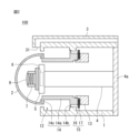
- FIG. 2 is a cross-sectional view of the imaging unit of FIG. 1
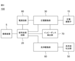
- FIG. 3 is a block diagram illustrating the hardware configuration of an imaging unit according to the embodiment
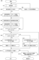
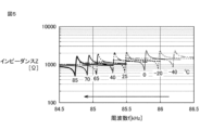
- 4 is a flow chart for explaining an example of the operation of the imaging unit according to the embodiment; 5 is a graph showing the relationship between resonance frequency, impedance, and temperature in the low frequency band of the vibrating section; 4 is a graph showing the relationship between the resonance frequency and the temperature in the low frequency band of the vibrating part; 4 is a graph showing the relationship between the minimum value of impedance and temperature in the low frequency band of the piezoelectric vibrator; 5 is a graph showing the relationship between the adhesion amount of water, which is an example of foreign matter, and the resonance frequency of the vibrating portion in the low frequency band. 5 is a graph showing the relationship between the amount of adhered water, which is an example of foreign matter, and the impedance of the piezoelectric vibrator in the low frequency band.
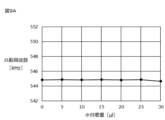
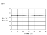
- FIG. 4 is a graph showing the relationship between the resonance frequency and the temperature in the high frequency band of the vibrating part; 4 is a graph showing the relationship between the minimum value of impedance and temperature in a high frequency band of a piezoelectric vibrator; 5 is a graph showing the relationship between the adhesion amount of water, which is an example of foreign matter, and the resonance frequency of the vibrating portion in a high frequency band. 4 is a graph showing the relationship between the amount of adhered water, which is an example of foreign matter, and the impedance of the piezoelectric vibrator in a high frequency band.
- FIG. 5 is a flowchart for explaining an example of the temperature estimation operation of FIG. 4; FIG. 4A and 4B are schematic timing charts for explaining a heating operation in the imaging unit according to the embodiment;
- a vibrating device includes: a translucent body; a vibrating body that vibrates the translucent body; a drive unit that drives the vibrating body; A control unit that controls the driving unit, The control unit determining a high frequency band resonance frequency of the vibrating body based on the state of the driving unit obtained by changing the driving frequency of the driving unit within a high frequency band of 100 kHz or higher; A temperature of the translucent body is estimated based on the determined high frequency band resonance frequency.
- the temperature of the translucent body can be estimated more accurately than the conventional technology.
- the control unit controlling the driving unit to vibrate the vibrating body at a high frequency of 100 kHz or more when the estimated temperature of the translucent body is less than a predetermined value;
- the above A low frequency band resonance frequency of the vibrating body may be determined, and the driving section may be controlled to vibrate the vibrating body at the determined low frequency band resonance frequency.
- the temperature of the translucent body can be increased as necessary, and foreign matter adhering to the translucent body can be easily removed.
- the control unit When the estimated temperature of the translucent body is less than a predetermined value, re-determining the high frequency band resonance frequency of the vibrating body based on the state of the driving unit obtained by changing the driving frequency of the driving unit within a high frequency band; re-estimating the temperature of the translucent body based on the re-determined high frequency band resonance frequency; If the re-estimated temperature of the transparent body is less than the predetermined value, until the re-estimated temperature of the transparent body reaches or exceeds the predetermined value, controlling the drive unit to vibrate the vibrator for a predetermined period of time at a frequency in a high frequency band; re-determining the high frequency band resonance frequency of the vibrator based on the state of the driving unit obtained by changing the driving frequency of the driving unit within the high frequency band after the predetermined period of time has elapsed; re-estimating the temperature of the translucent body based on the re-determined high frequency band resonance frequency.
- the temperature of the translucent body can be further increased as necessary, and foreign matter adhering to the translucent body can be easily removed.
- the vibrating device when the re-estimated temperature of the translucent body is equal to or higher than the predetermined value, or when the estimated temperature of the translucent body is equal to or higher than the predetermined value, determining a low frequency band resonance frequency of the vibrating body based on the state of the driving unit obtained by changing the driving frequency of the driving unit within a low frequency band of less than 100 kHz;
- the driving section may be controlled to vibrate the vibrator at the band resonance frequency.
- the vibrating device may further include a temperature sensor that measures the temperature of the translucent body, When the temperature of the translucent body measured by the temperature sensor is equal to or higher than the predetermined value, the control unit changes the driving frequency of the driving unit within a low frequency band of less than 100 kHz.
- a low frequency band resonance frequency of the vibrating body may be determined based on the state of the driving section, and the driving section may be controlled to vibrate the vibrating body at the determined low frequency band resonance frequency.
- the temperature of the translucent body can be controlled more accurately, making it easier to remove foreign matter adhering to the translucent body.
- the translucent body is arranged in the field of view of the imaging device,
- the control unit acquires a captured image from the imaging device and performs image processing on the captured image, and the result of the image processing indicates that no foreign matter adheres to the surface of the translucent body, determining a low frequency band resonance frequency of the vibrating body based on the state of the driving unit obtained by changing the driving frequency of the driving unit within a low frequency band of less than 100 kHz;
- the driving section may be controlled to vibrate the vibrator at the band resonance frequency.
- determining the low frequency band resonance frequency based on the state of the driving unit by the control unit includes: the control unit varying the drive frequency of the drive unit within a low frequency band and measuring the drive current of the drive unit; the controller determining the low frequency band resonance frequency based on the measured value of the drive current; may include
- determining the high frequency band resonance frequency based on the state of the driving unit by the control unit includes: the control unit measuring the driving current of the driving unit by changing the driving frequency of the driving unit within a high frequency band; the controller determining the high frequency band resonance frequency based on the measured value of the drive current; may include
- the controller may estimate the temperature T of the translucent body based on Equation (1).
- T A ⁇ fr+B (1) where A is a constant less than 0, B is a constant greater than 0, and fr is the resonance frequency of the oscillator.
- the temperature of the translucent body can be estimated more accurately.
- a vibration method includes: a translucent body; a vibrating body that vibrates the translucent body; a drive unit that drives the vibrating body; A vibration method performed by a vibration device comprising a control unit that controls the driving unit, determining a high frequency band resonance frequency of the vibrator based on the state of the driving unit obtained by changing the driving frequency of the driving unit within a high frequency band of 100 kHz or higher, by the control unit; , a step of estimating the temperature of the translucent body by the control unit based on the determined high frequency band resonance frequency; including.
- the temperature of the translucent body can be estimated more accurately than in the prior art.
- FIG. 1 is a perspective view showing a configuration example of an imaging unit 100 according to an embodiment of the present disclosure.
- Fig. 1 shows a virtual axis C for convenience of explanation.
- a direction parallel to the axis C is called an axial direction
- a direction perpendicular to the axis C is called a radial direction
- a circumferential direction about the axis C is called a circumferential direction.
- the axial direction the leftward direction on the paper surface of FIG. 1 is positive.
- the positive axial direction is also referred to as the distal side
- the negative axial direction is also referred to as the proximal side.
- the direction away from the axis C may be called outward, and the direction toward the axis C may be called inward.
- the imaging unit 100 includes a housing 1, a transparent protective cover 2 provided on one surface of the housing 1, and a cleaning nozzle 3.
- the cleaning nozzle 3 has an opening 31 for discharging a cleaning liquid (cleaning body) toward the protective cover 2 .
- FIG. 2 is a cross-sectional view of the imaging unit 100 of FIG.
- the imaging unit 100 further includes a vibrating section 12 that vibrates the protective cover 2 and an imaging device 5 .
- the imaging unit 100 has a configuration (imaging device 5) for capturing an image, a configuration (vibration device) for vibrating the protective cover 2 to remove foreign matter adhering to the protective cover 2, and a cleaning liquid ejected onto the protective cover 2 for protection. It also has a configuration (cleaning device) for removing foreign matter adhering to the cover 2 .
- the cleaning nozzle 3 is an example of a cleaning device.
- a base plate 4a is fixed to one end side of the housing 1, and a protective cover 2 and a vibrating section 12 are provided to the other end side of the housing 1.
- the imaging device 5 is supported by a cylindrical body member 4 and fixed to a base plate 4a.
- a circuit 6 including an imaging device is built in the imaging device 5 .
- a lens module 7 is fixed in the imaging direction of the imaging device 5 .
- the lens module 7 is formed of a cylindrical body and has a plurality of lenses 9 arranged in the axial direction inside.
- the structure of the imaging device 5 is not limited to this, and any structure capable of imaging a subject positioned in front of the lens 9 (on the front end side) may be employed.
- the vibrating portion 12 includes a cylindrical first cylindrical member 13 centered on the axis C, a cylindrical second cylindrical member 14 centered on the axis C, and a cylindrical piezoelectric vibrator centered on the axis C. child 15;
- the vibrating section 12 is an example of a vibrating body.
- the piezoelectric vibrator 15 is sandwiched between the first tubular member 13 and the second tubular member 14 .
- the piezoelectric vibrator 15 has cylindrical piezoelectric plates 16 and 17 .
- the piezoelectric plates 16 and 17 are each axially polarizable.
- the polarization direction of the piezoelectric plate 16 is configured to be opposite to the polarization direction of the piezoelectric plate 17 .
- the piezoelectric plates 16 and 17 include, for example, lead zirconate titanate piezoelectric ceramics, (K,Na) NbO3 piezoelectric ceramics, or LiTaO3 piezoelectric single crystals.
- An electrode (not shown) is formed on each of the piezoelectric plates 16 and 17 .
- This electrode has a laminated structure of Ag/NiCu/NiCr, for example.
- the first cylindrical member 13 and the second cylindrical member 14 are made of, for example, metals such as duralumin, stainless steel, and kovar, or semiconductors such as conductive Si.
- the piezoelectric vibrator 15 can be vibrated in the vertical or horizontal direction.
- the first tubular member 13 has a male threaded portion on at least a portion of its outer surface
- the second tubular member 14 has a female threaded portion on at least a portion of its inner surface.
- the first cylindrical member 13 is screwed into the second cylindrical member 14 by these screws, and the first cylindrical member 13 is fixed to the second cylindrical member 14 .
- a part of the first cylindrical member 13 and a part of the second cylindrical member 14 are pressed against one surface and the other surface of the piezoelectric vibrator 15, respectively.
- the vibration generated in the piezoelectric vibrator 15 efficiently vibrates the vibrating section 12 as a whole.
- the vibrating portion 12 is efficiently excited by the vertical effect or the horizontal effect.
- the second tubular member 14 has a tubular thin portion 14a and flange portions 14b and 14c.
- the flange portion 14c protrudes outward from the thin portion 14a at the tip of the second tubular member 14 .
- the flange portion 14b protrudes outward from the thin portion 14a on the base end side of the flange portion 14c of the second tubular member 14 .
- the thickness of the thin portion 14 a is thinner than the thickness of the first tubular member 13 . Therefore, the tubular thin portion 14a is largely displaced by the vibration of the vibrating portion 12, and the vibration, particularly the amplitude, can be increased.
- the protective cover 2 is fixed to the flange portion 14c.
- the protective cover 2 has a hemispherical shape.
- the protective cover 2 is an example of a translucent body that transmits light from a subject.
- the material of the protective cover 2 is, for example, soda glass, borosilicate glass, aluminosilicate glass, or a combination thereof.
- the protective cover 2 may be tempered glass whose strength is increased by chemical strengthening or the like.
- the surface of the protective cover 2 may be coated with an antireflection film, a water-repellent material, an impact-resistant material, or the like.
- the cleaning nozzle 3 is supplied with the cleaning liquid from the base end side, and discharges the cleaning liquid to the protective cover 2 through the inner tube and the opening 31 extending in the axial direction.
- the tip of the cleaning nozzle 3 is outside the imaging range (field of view) of the imaging device 5 and does not appear in the image captured by the imaging device 5 .
- the configuration in which the imaging unit 100 includes one cleaning nozzle 3 is shown, but the imaging unit 100 may include a plurality of cleaning nozzles 3 .
- FIG. 3 is a block diagram illustrating the hardware configuration of the imaging unit 100. As shown in FIG. The imaging unit 100 further includes a signal processing circuit 20 , a piezoelectric drive section 30 , a cleaning liquid discharge section 50 , a cleaning drive section 60 , an impedance detection section 70 and a power supply circuit 80 .
- the signal processing circuit 20 is a control section that processes signals from the imaging device 5 and supplies control signals to the imaging device 5 , the piezoelectric drive section 30 and the cleaning drive section 60 . Such information processing is realized, for example, by the signal processing circuit 20 operating according to a program instruction.
- the signal processing circuit 20 includes a CPU (Central Processing Unit), ROM (Read Only Memory), RAM (Random Access Memory), an input/output interface for maintaining signal consistency with peripheral devices, and the like.
- the ROM stores, for example, programs for the CPU to operate, control data, and the like.
- the RAM functions as a work area for the CPU.
- the piezoelectric driving section 30 generates an AC output signal according to the control signal from the signal processing circuit 20 and transmits it to the piezoelectric vibrator 15 .
- the AC output signal contains information about frequency and voltage, for example.
- the piezoelectric vibrator 15 vibrates based on the received AC output signal to vibrate the vibrating portion 12 and the protective cover 2 .
- the cleaning driving section 60 causes the cleaning liquid discharge section 50 to supply the cleaning liquid based on the control signal from the signal processing circuit 20 .
- the supplied cleaning liquid is discharged to the protective cover 2 through the opening 31 of the cleaning nozzle 3 .
- the impedance detection unit 70 monitors electrical characteristics of the piezoelectric drive unit 30 such as the drive current and impedance when the piezoelectric drive unit 30 applies an AC output signal to the piezoelectric vibrator 15 to operate the piezoelectric vibrator 15 . do.
- the impedance detector 70 is an example of a controller, and may be provided separately from the signal processing circuit 20 as shown in FIG. 3 or may be provided integrally with the signal processing circuit 20 .
- FIG. 4 is a flowchart for explaining an operation example of the imaging unit 100 . The operations of FIG. 4 are performed by the signal processing circuit 20 .
- the signal processing circuit 20 estimates the temperature of the protective cover 2 based on the drive current of the piezoelectric drive section 30 (S1). Details of the temperature estimation step S1 will be described later.
- the signal processing circuit 20 determines whether the temperature estimated in step S1 is less than 0°C, which is the lower limit threshold (S2).
- the lower threshold is not limited to 0.degree. C., and may be set to a temperature preselected from -4.degree. C. to +4.degree.
- step S3 If the temperature estimated in step S1 is less than 0° C. (Yes in S2), the signal processing circuit 20 causes the piezoelectric driving section 30 to operate the piezoelectric vibrator 15 in heating mode for a predetermined time (S3).
- the heating mode is a mode in which the piezoelectric vibrator 15 is vibrated at frequencies in a high frequency band, and the vibration can raise the temperature of the protective cover 2 .
- the signal processing circuit 20 returns to step S1.
- step S1 If the temperature estimated in step S1 is not below 0° C. (No in S2), that is, if it is above 0° C., the signal processing circuit 20 causes the piezoelectric vibrator 15 to operate in the low frequency band search mode (S4). .
- the low frequency band search mode in step S4 is a mode for searching for the resonance frequency of the vibrating section 12 in the low frequency band (hereinafter referred to as "low frequency band resonance frequency").
- low frequency means frequencies below 100 kHz and high frequency means frequencies above 100 kHz.
- the piezoelectric driving section 30 sets the driving voltage Vdr of the piezoelectric vibrator 15 to V1, sweeps the driving frequency f, and applies an AC output signal to the piezoelectric vibrator 15 .
- the impedance detection section 70 monitors the current value or impedance of the piezoelectric drive section 30. Specifically, the impedance detection unit 70 measures the impedance that is the reciprocal of the current value or the current value flowing through the piezoelectric driving unit 30 .
- the signal processing circuit 20 acquires the driving frequency f and the current value or impedance, and determines the driving frequency f at which the current value is the maximum value I_low0 or the driving frequency f at which the impedance is the minimum value as the initial resonance frequency fr_low0. Thus, the signal processing circuit 20 measures the maximum current value I_low0 and the corresponding initial resonance frequency fr_low0.
- the signal processing circuit 20 updates the memory with the initial resonance frequency fr_low0 and the current value I_low0 measured in step S4 as the reference frequency fr and the reference current value I, respectively (step S5).
- Step S6 is executed, for example, after a certain period of time, for example, one second after step S4.
- FIG. 5 is a graph showing the relationship between the low frequency band resonance frequency of the vibrating section 12, impedance, and temperature.
- the horizontal axis of the graph in FIG. 5 indicates frequency [kHz], and the vertical axis indicates impedance [ ⁇ ].
- the graph of FIG. 5 shows how the low frequency band resonance frequency changes when the temperature is changed from -40.degree. C. to 85.degree.
- the frequency at which the impedance changes abruptly is the low frequency band resonance frequency.
- the low frequency band resonance frequency decreases as the temperature rises.
- the low frequency band resonance frequency decreases as the amount or weight of the foreign matter adhering to the surface of the protective cover 2 increases. That is, the lowering of the low frequency band resonance frequency is caused not only by temperature rise but also by adhesion of foreign matter. Therefore, by only measuring the change in the low frequency band resonance frequency with the impedance detection unit 70, it is not possible to distinguish between the adhesion of foreign matter to the surface of the protective cover 2 and the temperature change.
- the signal processing circuit 20 makes a judgment by referring only to the low-frequency band resonance frequency, even though the low-frequency band resonance frequency has actually decreased due to the temperature rise, the decrease is caused by the surface of the protective cover 2.
- the signal processing circuit 20 controls to increase the vibration amplitude of the piezoelectric vibrator 15 in order to remove the foreign matter. will be performed.
- Increasing the vibration amplitude of the piezoelectric vibrator 15 further increases the surface temperature of the protective cover 2 .
- the signal processing circuit 20 becomes even more unstable when foreign matter adheres to the surface of the protective cover 2, making it difficult to make an accurate judgment.
- Changes in the low frequency band resonance frequency are caused not only by temperature changes, but also by aging of the joint between the protective cover 2 and the vibrating portion 12, moisture absorption by the resin portion, and the like.
- the signal processing circuit 20 may determine that a foreign object has adhered to the surface of the protective cover 2 together with information other than the change in the low frequency band resonance frequency.
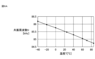
- FIG. 6A is a graph showing the relationship between the low frequency band resonance frequency and temperature.
- the horizontal axis of FIG. 6A indicates the temperature [° C.], and the vertical axis indicates the low frequency band resonance frequency [kHz].
- the low frequency band resonance frequency decreases as the temperature increases.
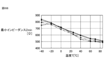
- FIG. 6B is a graph showing the relationship between the minimum impedance (minimum value of impedance) in the low frequency band of the piezoelectric vibrator 15 and temperature.
- the horizontal axis of FIG. 6B indicates temperature [° C.], and the vertical axis indicates minimum impedance [ ⁇ ].
- the minimum impedance of the piezoelectric vibrator 15 in the low frequency band decreases as the temperature increases.
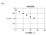
- FIG. 7A is a graph showing the relationship between the adhesion amount of water, which is an example of foreign matter, and the low frequency band resonance frequency.
- the horizontal axis of FIG. 7A indicates the volume of water adhering to the surface of the protective cover 2 (hereinafter referred to as "water adhering amount") [ ⁇ l], and the vertical axis indicates the low frequency band resonance frequency [kHz].
- water adhering amount the volume of water adhering to the surface of the protective cover 2
- kHz low frequency band resonance frequency
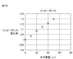
- FIG. 7B is a graph showing the relationship between the adhesion amount of water, which is an example of foreign matter, and the minimum impedance of the piezoelectric vibrator 15 in the low frequency band.
- the horizontal axis of FIG. 7B indicates the water adhesion amount [ ⁇ l], and the vertical axis indicates the impedance change rate.
- the change rate of the minimum impedance of the piezoelectric vibrator 15 increases as the amount of attached water increases.
- the change rate of the current value I corresponding to the minimum impedance of the piezoelectric vibrator 15 decreases as the amount of attached water increases.
- the signal processing circuit 20 combines changes in the low frequency band resonance frequency and changes in the minimum impedance of the piezoelectric vibrator 15 to determine do. This makes it possible to accurately determine whether these changes are caused by foreign matter adhering to the surface of the protective cover 2 or by temperature changes.
- the minimum impedance of the piezoelectric vibrator 15 also changes due to aging of the joint between the protective cover 2 and the vibrating part 12 and moisture absorption of the resin part. Since it is different from the change in the case, it is possible to make a judgment by distinguishing between the two.
- the low frequency band resonance frequency and minimum impedance decrease as the temperature increases. Further, as the amount of foreign matter adhering to the surface of the protective cover 2 increases, the low frequency band resonance frequency decreases while the rate of change of the minimum impedance increases.
- the signal processing circuit 20 executes the process corresponding to this determination by the above step S7.
- the signal processing circuit 20 detects that the amount of change ( ⁇ fr) for decreasing the resonance frequency is equal to or less than the first frequency threshold fth and the amount of change ( ⁇ I) for decreasing the current value is equal to or less than the first current threshold Ith. , it is determined that foreign matter has adhered to the surface of the protective cover 2 . In this manner, the signal processing circuit 20 does not determine the presence or absence of a foreign object on the surface of the protective cover 2 based only on the amount of change (time change) in the resonance frequency, but rather the amount of change (time change) in the current value, which is a value related to impedance. ) can also be used to determine the presence or absence of foreign matter.
- step S5 when determining that the difference values ⁇ f and ⁇ I are greater than the first threshold (No in S7), the signal processing circuit 20 returns the process to step S5. In this case, it is presumed that foreign matter does not adhere to the surface of the protective cover 2 .
- step S5 which is executed again, the signal processing circuit 20 updates the memory with the resonance frequency fr_low1 and the current value I_low1 measured in step S6 as the reference frequency fr and the reference current value I, respectively.
- the signal processing circuit 20 sets the difference values ⁇ f and ⁇ I to a second threshold different from the first threshold. It is determined whether or not (S8). Specifically, the signal processing circuit 20 determines whether or not the difference value ⁇ f ⁇ fth1 and ⁇ I ⁇ Ith1.
- the absolute value of the second frequency threshold fth1 is greater than the absolute value of the first frequency threshold fth (fth1>fth), and the second current threshold Ith1 is greater than the first current threshold Ith (Ith1>Ith). .
- the signal processing circuit 20 performs specific processing when the difference values ⁇ f and ⁇ I are equal to or less than the second threshold value, thereby determining whether the amount of foreign matter adhering to the surface of the protective cover 2 is large or heavy (the degree of contamination is severe). ), corresponding processing can be performed.
- the signal processing circuit 20 determines the presence or absence of foreign matter adhering to the surface of the protective cover 2 from the first threshold values fth and Ith, and determines the degree of foreign matter adhering to the surface of the protective cover 2 from the second threshold values fth1 and Ith1. are doing.
- step S8 If it is determined in step S8 that the difference values ⁇ f and ⁇ I are greater than the second threshold value (No in S8), the signal processing circuit 20 sets the driving voltage Vdr of the piezoelectric driving section 30 to V2, and the driving frequency fdr is set as the resonance frequency fmax (S9).
- V2 is greater than V1.
- the signal processing circuit 20 executes drive mode A in which only the piezoelectric drive section 30 is driven with the drive voltage and resonance frequency set in step S9 (S10).
- drive mode A of step S10 the signal processing circuit 20 drives only the piezoelectric drive section 30 without driving the cleaning drive section 60.
- step S8 if it is determined in step S8 that the difference values ⁇ f and ⁇ I are equal to or less than the second threshold value (Yes in S8), the signal processing circuit 20 sets the driving voltage Vdr of the piezoelectric driving section 30 to V3, The drive frequency fdr is set to the resonance frequency fmax (S11).
- V3 is less than V2.
- the signal processing circuit 20 drives the piezoelectric drive section 30 with the drive voltage and resonance frequency set in step S11, and executes drive mode B in which the cleaning drive section 60 is also driven (S12). Since the drive voltage V3 in drive mode B is smaller than the drive voltage V2 in drive mode A, in drive mode B, the piezoelectric drive unit 30 vibrates the piezoelectric vibrator 15 weaker than in drive mode A.
- the signal processing circuit 20 can more powerfully clean the foreign matter adhering to the protective cover 2 .
- the signal processing circuit 20 has a stronger cleaning power than the cleaning liquid discharged in the drive mode B based on at least one of the resonance frequency, the impedance-related value (current value), and the image captured by the imaging device 5.
- the cleaning drive 60 may be controlled to use .
- the signal processing circuit 20 determines whether or not the current value Idr measured by the impedance detector 70 has increased to a predetermined value or more (S13).
- current value Idr measured by impedance detector 70 increases to a predetermined value or more. In other words, the current value Idr measured by the impedance detection unit 70 almost returns to the value of the current value Idr when no foreign matter adheres to the surface of the protective cover 2 .
- the signal processing circuit 20 determines whether or not the current value Idr measured by the impedance detection unit 70 has increased to a predetermined value or more, thereby determining whether or not the foreign matter adhering to the surface of the protective cover 2 has been removed. information is obtained.
- step S13 When it is determined in step S13 that the current value Idr has increased to the predetermined value or more (Yes in S13), the signal processing circuit 20 ends the processing of FIG. Alternatively, the signal processing circuit 20 determines whether or not an operation to end the cleaning process has been accepted, and if so, ends the process of FIG. 4. If not, the process proceeds to step S1 or S4. You can return it.
- step S13 If it is determined in step S13 that the current value Idr has not increased to or above the predetermined value (No in S13), the signal processing circuit 20 determines that the operation time in drive mode A or B exceeds the threshold value (for example, 1 minute). It is determined whether or not there is (S14). In step S14, for example, if the sum of the operating time in drive mode A and the operating time in drive mode B exceeds the threshold, the signal processing circuit 20 determines that the operating time in drive mode A or B exceeds the threshold. I judge.
- the threshold value for example, 1 minute
- the signal processing circuit 20 terminates the processing in FIG. 4 due to an abnormality (abnormal termination). If the piezoelectric vibrator 15 is driven for a long time in the drive mode for cleaning, problems such as the protective cover 2 generating heat may occur. By always ending the signal processing circuit 20 in a predetermined case, it is possible to prevent such a problem from occurring.
- step S13 When it is determined in step S13 that the current value Idr has not increased to a predetermined value or more (No in S13) and it is determined that the operation time in drive mode A or B has not exceeded the threshold value (No in S14). , the signal processing circuit 20 returns the process to step S8.
- Temperature estimation 2-2-1 Knowledge Regarding Temperature Estimation
- the temperature estimation step S1 in FIG. 4 will be described below.
- knowledge regarding temperature estimation will be described with reference to FIGS.
- the inventors have made intensive studies on the relationship between the vibration of the protective cover 2 and the temperature, obtained knowledge regarding temperature estimation as shown below, and developed a technique for estimating the temperature of the protective cover 2 based on the obtained knowledge. I came to create an idea.
- FIG. 8A is a graph showing the relationship between the resonance frequency of the vibrating section 12 in the high frequency band (hereinafter referred to as "high frequency band resonance frequency”) and the temperature.
- FIG. 8B is a graph showing the relationship between the minimum impedance of the piezoelectric vibrator 15 and temperature in the high frequency band. In the graphs of FIGS. 8A and 8B, each black circle indicates an actual measurement value.
- FIG. 9A is a graph showing the relationship between the water adhesion amount and the high frequency band resonance frequency.
- FIG. 9B is a graph showing the relationship between the water adhesion amount and the minimum impedance of the piezoelectric vibrator 15 in the high frequency band.
- each black circle indicates an actual measurement value. From the graphs shown in FIGS. 9A and 9B, there is no correlation between the water adhesion amount and the high frequency band resonance frequency, nor between the water adhesion amount and the minimum impedance of the piezoelectric vibrator 15 in the high frequency band. I understand.
- the temperature of the protective cover 2 in this embodiment can be estimated based on the high frequency band resonance frequency. Specifically, in the high frequency band, the temperature T of the protective cover 2 can be estimated based on the following equation (1) using the resonance frequency fr of the vibrating section 12.
- T A ⁇ fr+B (1) where A is a constant less than 0 and B is a constant greater than 0.
- the relationship (1) holds when the spring constant of the vibrating member has temperature dependence.
- the spring constant represents the ease of extension of the member.
- the spring constant of a member that tends to expand as the temperature rises decreases as the temperature rises.
- the frequency of vibration of a member that tends to stretch when the temperature rises becomes lower as the temperature rises.
- the amount of adhered foreign matter does not correlate with either the resonance frequency of the high frequency band or the minimum impedance of the piezoelectric vibrator 15 in the high frequency band. It works even if it sticks to the body. Therefore, the temperature of the vibrating vibrating portion 12 and the protective cover 2 can be estimated more accurately than in the prior art by using the formula (1) regardless of the presence or absence of adhesion of foreign matter.
- FIG. 10 is a flowchart for explaining an example of the temperature estimating step S1 in FIG.
- the signal processing circuit 20 causes the piezoelectric driving section 30 to operate the piezoelectric vibrator 15 in the high frequency band search mode (S101).
- the high frequency band search mode in step S101 is a mode for searching for the resonance frequency of the vibrating section 12 in the high frequency band.
- the piezoelectric driving section 30 applies the AC output signal to the piezoelectric vibrator 15 by setting the driving voltage Vdr of the piezoelectric vibrator 15 to V4 and sweeping the driving frequency f within the high frequency band.
- the impedance detection unit 70 monitors the current value or impedance of the piezoelectric drive unit 30 during the high frequency band search mode in step S101. Specifically, the impedance detection unit 70 measures the impedance that is the reciprocal of the current value or the current value flowing through the piezoelectric driving unit 30 .
- the signal processing circuit 20 obtains the driving frequency f and the current value or impedance, and selects the driving frequency f at which the current value is the maximum value I0_high or the driving frequency f at which the impedance is the minimum value in the high frequency band.
- the resonance frequency f0_high is determined (S102).
- the signal processing circuit 20 measures the maximum current value I0_high and the high frequency band resonance frequency f0_high corresponding thereto.
- the signal processing circuit 20 calculates the estimated temperatures of the vibrating section 12 and the protective cover 2 based on the high frequency band resonance frequency f0_high determined in step S102 (S103). Specifically, the signal processing circuit 20 calculates the estimated temperature T by substituting the high-frequency band resonance frequency f0_high measured in step S102 into fr in Equation (1).
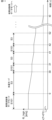
- FIG. 11 is a schematic graph for explaining such a heating operation in the imaging unit 100.
- the horizontal axis of the graph in FIG. 11 indicates time [s], and the vertical axis indicates the high frequency band resonance frequency f0_high [kHz].
- the signal processing circuit 20 operates in the high frequency band search mode (S101), determines the high frequency band resonance frequency f0_high (S102), and calculates the estimated temperature (S103). If the estimated temperature is 0° C. or higher, the signal processing circuit 20 operates in the heating mode (S3) to increase the temperature of the protective cover 2. As the temperature of the protective cover 2 increases, the high frequency band resonance frequency f0_high decreases.
- the operation time of the heating mode is, for example, 30 seconds for the first time and 10 seconds for the second and subsequent times, but is not limited to this.
- the high frequency band search mode is executed for, for example, one second each time.
- the vibrating device includes the protective cover 2 that is an example of a translucent body, the vibrating section 12 that is an example of a vibrating body that vibrates the protective cover 2, and the vibrating section 12.
- a piezoelectric driving unit 30 for driving and a signal processing circuit 20 which is an example of a control unit for controlling the piezoelectric driving unit 30 are provided.
- the signal processing circuit 20 adjusts the high frequency band resonance of the vibrating portion 12 based on the state of the piezoelectric driving portion 30 obtained by changing the driving frequency of the piezoelectric driving portion 30 within a high frequency band of 100 kHz or more (S101).
- the frequency is determined (S102), and the temperature of the protective cover 2 is estimated based on the determined high frequency band resonance frequency (S103).
- the temperature of the protective cover 2 can be estimated more accurately than the conventional technology.
- the signal processing circuit 20 vibrates the vibrating portion 12 at a high frequency of 100 kHz or higher (S3). section 30 may be controlled.
- the signal processing circuit 20 changes the drive frequency of the piezoelectric drive unit 30 within a low frequency band of less than 100 kHz. Based on the state of the piezoelectric drive unit 30, the low frequency band resonance frequency of the vibration unit 12 is determined (S4, S6), and the piezoelectric drive unit is operated to vibrate the vibration unit 12 at the low frequency band resonance frequency (S9, S11). 30 may be controlled.
- the temperature of the protective cover 2 can be increased when the temperature of the protective cover 2 is less than the predetermined value. As a result, for example, foreign substances such as ice and snow can be melted and removed from the protective cover 2 .
- the signal processing circuit 20 sets the driving frequency of the piezoelectric driving section 30 to a high frequency band.
- the high frequency band resonance frequency of the vibrating section 12 may be determined again based on the state of the piezoelectric driving section 30 obtained by changing the internal frequency.
- the signal processing circuit 20 may re-estimate the temperature of the protective cover 2 based on the re-determined high frequency band resonance frequency. If the reestimated temperature of the protective cover 2 is less than the predetermined value, the signal processing circuit 20 continues until the reestimated temperature of the protective cover 2 reaches or exceeds the predetermined value.
- the piezoelectric drive unit 30 controlling the piezoelectric drive unit 30 to vibrate the vibrating unit 12 for a predetermined period of time at a frequency in the high frequency band; After a predetermined period of time has passed, the high frequency band resonance frequency of the vibrating portion 12 is determined again based on the state of the piezoelectric driving portion 30 obtained by changing the driving frequency of the piezoelectric driving portion 30 within the high frequency band. , Re-estimating the temperature of the protective cover 2 based on the re-determined high frequency band resonance frequency may be repeated.
- the temperature of the protective cover 2 can be increased until the temperature of the protective cover 2 reaches or exceeds a predetermined value.
- foreign substances such as ice and snow can be melted and removed from the protective cover 2 .
- the signal processing circuit 20 changes the drive frequency of the piezoelectric drive unit 30 to
- the low frequency band resonance frequency of the vibrating portion 12 is determined based on the state of the piezoelectric driving portion 30 obtained by changing within a low frequency band of less than 100 kHz, and the vibrating portion 12 is vibrated at the low frequency band resonance frequency.
- the piezoelectric driving section 30 may be controlled as follows.
- the signal processing circuit 20 may estimate the temperature T of the protective cover 2 based on Equation (1).
- T A ⁇ fr+B (1)
- A is a constant less than 0
- B is a constant greater than 0
- fr is the resonance frequency of the vibrating section 12 .
- the temperature of the protective cover 2 can be estimated more accurately.
- the vibration device may include a temperature sensor that measures the temperature of the protective cover 2, and the temperature of the protective cover 2 may be measured by the temperature sensor in addition to or instead of the temperature estimation step S1. With this configuration, the temperature of the protective cover 2 can be measured more accurately.
- the signal processing circuit 20 determines the presence and degree of foreign matter on the surface of the protective cover 2 based on the measurement results of the resonance frequency and the current value has been described, but the present disclosure is not limited to this.
- the signal processing circuit 20 may acquire a captured image from the imaging device 5, perform image processing, and determine the presence or absence and degree of foreign matter on the surface of the protective cover 2 using the result of the image processing.
- the signal processing circuit 20 in addition to the amount of change (time change) in the resonance frequency fr and the amount of change (time change) in the current value I, Information on the temporal change of the image captured by the imaging device 5 may be taken into consideration. Further, the signal processing circuit 20 combines the change amount (time change) of the resonance frequency fr and the time change of the image captured by the imaging device 5 in order to determine whether a foreign object has adhered to the surface of the protective cover 2. good too. Further, the signal processing circuit 20 combines the change amount (time change) of the current value Ir and the time change of the image captured by the imaging device 5 in order to determine whether a foreign object has adhered to the surface of the protective cover 2. good too.
- the signal processing circuit 20 determines that foreign matter has adhered to the surface of the protective cover 2. can be judged. As a result, the signal processing circuit 20 considers the amount of change in the resonance frequency fr. can be distinguished from the decrease in the integrated brightness value caused by the adhesion of .
- the amount of change in the resonance frequency fr and the amount of change in the current value I are greater than the absolute values of the threshold values fth and Ith, respectively, and the integrated brightness value of the image captured by the image capturing device 5 has decreased significantly.
- the foreign matter adhering to the surface of the protective cover 2 is an opaque substance such as mud.
- the signal processing circuit 20 determines that the foreign matter adhering to the surface of the protective cover 2 is a transparent substance such as water when the decrease in the integrated brightness value of the image captured by the imaging device 5 is small. In this manner, the signal processing circuit 20 can more accurately determine the type of foreign matter adhering to the surface of the protective cover 2 by taking into consideration the time change information of the image captured by the imaging device 5 .
- the signal processing circuit 20 determines that the temperature of the protective cover 2 is equal to or higher than a predetermined upper threshold value, the signal processing circuit 20 executes processing for preventing the temperature rise of the protective cover 2 or processing for cooling the protective cover 2.
- processing for preventing the temperature rise of the protective cover 2 is to stop driving the piezoelectric driving section 30, thereby stopping vibration of the piezoelectric vibrator 15, the vibrating section 12, and the protective cover 2.
- FIG. One example of a process for cooling the protective cover 2 is to use the cleaning nozzles 3 to eject a cleaning liquid or other liquid such as a cooling liquid onto the protective cover 2 .
Landscapes
- Engineering & Computer Science (AREA)
- Physics & Mathematics (AREA)
- Multimedia (AREA)
- Signal Processing (AREA)
- General Physics & Mathematics (AREA)
- Mechanical Engineering (AREA)
- Acoustics & Sound (AREA)
- Aviation & Aerospace Engineering (AREA)
- Electromagnetism (AREA)
- Apparatuses For Generation Of Mechanical Vibrations (AREA)
- Camera Bodies And Camera Details Or Accessories (AREA)
Abstract
Description
透光体と、
前記透光体を振動させる振動体と、
前記振動体を駆動する駆動部と、
前記駆動部を制御する制御部と、を備え、
前記制御部は、
前記駆動部の駆動周波数を100kHz以上の高周波数帯域内で変化させることにより得られた前記駆動部の状態に基づいて、前記振動体の高周波数帯共振周波数を決定し、
決定された前記高周波数帯共振周波数に基づいて、前記透光体の温度を推定する。
透光体と、
前記透光体を振動させる振動体と、
前記振動体を駆動する駆動部と、
前記駆動部を制御する制御部と、を備える振動装置によって行われる振動方法であって、
前記制御部が、前記駆動部の駆動周波数を100kHz以上の高周波数帯域内で変化させることにより得られた前記駆動部の状態に基づいて、前記振動体の高周波数帯共振周波数を決定するステップと、
前記制御部が、決定された前記高周波数帯共振周波数に基づいて、前記透光体の温度を推定するステップと、
を含む。
透光体と、
前記透光体を振動させる振動体と、
前記振動体を駆動する駆動部と、
前記駆動部を制御する制御部と、を備え、
前記制御部は、
前記駆動部の駆動周波数を100kHz以上の高周波数帯域内で変化させることにより得られた前記駆動部の状態に基づいて、前記振動体の高周波数帯共振周波数を決定し、
決定された前記高周波数帯共振周波数に基づいて、前記透光体の温度を推定する。
推定された前記透光体の温度が所定値未満である場合、100kHz以上の高周波数で前記振動体を振動させるように前記駆動部を制御し、
前記推定された透光体の温度が前記所定値以上である場合、前記駆動部の駆動周波数を100kHz未満の低周波数帯域内で変化させることにより得られた前記駆動部の状態に基づいて、前記振動体の低周波数帯共振周波数を決定し、決定された前記低周波数帯共振周波数で前記振動体を振動させるように前記駆動部を制御してもよい。
推定された前記透光体の温度が所定値未満である場合、
前記駆動部の駆動周波数を高周波数帯域内で変化させることにより得られた前記駆動部の状態に基づいて前記振動体の高周波数帯共振周波数を再度決定し、
前記再度決定された高周波数帯共振周波数に基づいて、前記透光体の温度を再度推定し、
再度推定された前記透光体の温度が前記所定値未満である場合、前記再度推定された透光体の温度が前記所定値以上となるまで、
高周波数帯域の周波数で、所定期間、前記振動体を振動させるように前記駆動部を制御することと、
前記所定期間の経過後、前記駆動部の駆動周波数を高周波数帯域内で変化させることにより得られた前記駆動部の状態に基づいて前記振動体の高周波数帯共振周波数を再度決定することと、
前記再度決定された高周波数帯共振周波数に基づいて、前記透光体の温度を再度推定することと、を繰り返してもよい。
前記制御部は、前記温度センサによって測定された前記透光体の温度が前記所定値以上である場合、前記駆動部の駆動周波数を100kHz未満の低周波数帯域内で変化させることにより得られた前記駆動部の状態に基づいて、前記振動体の低周波数帯共振周波数を決定し、決定された前記低周波数帯共振周波数で前記振動体を振動させるように前記駆動部を制御してもよい。
前記透光体は、撮像装置の視野に配置され、
前記制御部は、前記撮像装置から撮像画像を取得して前記撮像画像に画像処理を実行し、前記画像処理の結果が、前記透光体の表面に異物が付着していないことを示す場合、前記駆動部の駆動周波数を100kHz未満の低周波数帯域内で変化させることにより得られた前記駆動部の状態に基づいて、前記振動体の低周波数帯共振周波数を決定し、決定された前記低周波数帯共振周波数で前記振動体を振動させるように前記駆動部を制御してもよい。
前記制御部が、前記駆動部の駆動周波数を低周波数帯域内で変化させて前記駆動部の駆動電流を測定することと、
前記制御部が、測定された前記駆動電流の値に基づいて前記低周波数帯共振周波数を決定することと、
を含んでもよい。
前記制御部が、前記駆動部の駆動周波数を高周波数帯域内で変化させて前記駆動部の駆動電流を測定することと、
前記制御部が、測定された前記駆動電流の値に基づいて前記高周波数帯共振周波数を決定することと、
を含んでもよい。
T=A・fr+B ・・・(1)
ここで、Aは、0より小さい定数であり、Bは、0より大きい定数であり、frは、前記振動体の共振周波数である。
透光体と、
前記透光体を振動させる振動体と、
前記振動体を駆動する駆動部と、
前記駆動部を制御する制御部と、を備える振動装置によって行われる振動方法であって、
前記制御部が、前記駆動部の駆動周波数を100kHz以上の高周波数帯域内で変化させることにより得られた前記駆動部の状態に基づいて、前記振動体の高周波数帯共振周波数を決定するステップと、
前記制御部が、決定された前記高周波数帯共振周波数に基づいて、前記透光体の温度を推定するステップと、
を含む。
1-1.全体構成
図1は、本開示の実施の形態に係る撮像ユニット100の構成例を示す斜視図である。
図3は、撮像ユニット100のハードウェア構成を例示するブロック図である。撮像ユニット100は、信号処理回路20、圧電駆動部30、洗浄液吐出部50、洗浄駆動部60、インピーダンス検出部70、及び電源回路80を更に備える。
2-1.全体動作
図4は、撮像ユニット100の動作例を説明するためのフローチャートである。図4の動作は、信号処理回路20によって実行される。
2-2-1.温度推定に関する知見
以下、図4の温度推定ステップS1について説明するが、その前提として、図8A,8B,9A及び9Bを用いて温度推定に関する知見について説明する。発明者らは、保護カバー2の振動と温度との関係について鋭意研究し、以下に示すような温度推定に関する知見を得、さらに、得られた知見に基づいて保護カバー2の温度を推定する技術的思想を創作するに至った。
ここで、Aは、0より小さい定数であり、Bは、0より大きい定数である。
図10は、図4の温度推定ステップS1の一例を説明するためのフローチャートである。
図4に示したように、温度推定ステップS1及び加温ステップS3は、推定温度が0℃以上(S2でNo)となるまで繰り返される。図11は、撮像ユニット100におけるこのような加温動作を説明するための模式的なグラフである。
以上のように、本開示の一態様に係る振動装置は、透光体の一例である保護カバー2と、保護カバー2を振動させる振動体の一例である振動部12と、振動部12を駆動する圧電駆動部30と、圧電駆動部30を制御する制御部の一例である信号処理回路20と、を備える。信号処理回路20は、圧電駆動部30の駆動周波数を100kHz以上の高周波数帯域内で変化させる(S101)ことにより得られた圧電駆動部30の状態に基づいて、振動部12の高周波数帯共振周波数を決定し(S102)、決定され記高周波数帯共振周波数に基づいて、保護カバー2の温度を推定する(S103)。
高周波数帯域の周波数で、所定期間、振動部12を振動させるように圧電駆動部30を制御することと、
所定期間の経過後、圧電駆動部30の駆動周波数を高周波数帯域内で変化させることにより得られた圧電駆動部30の状態に基づいて振動部12の高周波数帯共振周波数を再度決定することと、
再度決定された高周波数帯共振周波数に基づいて、保護カバー2の温度を再度推定することと、を繰り返してもよい。
T=A・fr+B ・・・(1)
ここで、Aは、0より小さい定数であり、Bは、0より大きい定数であり、frは、振動部12の共振周波数である。
以上、本開示の実施の形態を詳細に説明したが、前述までの説明はあらゆる点において本開示の例示に過ぎない。本開示の範囲を逸脱することなく種々の改良や変形を行うことができる。例えば、以下のような変更が可能である。なお、以下では、上記実施の形態と同様の構成要素に関しては同様の符号を用い、上記実施の形態と同様の点については、適宜説明を省略する。以下の変形例は適宜組み合わせることができる。
上記実施の形態では、高周波数帯共振周波数に基づいて保護カバー2の温度を推定する例について説明したが、本開示はこれに限定されない。例えば、振動装置は、保護カバー2の温度を測定する温度センサを備え、温度推定ステップS1に加えて、又はこれに代えて、温度センサによって保護カバー2の温度を測定してもよい。この構成によれば、より正確に保護カバー2の温度を測定することができる。
上記実施の形態では、信号処理回路20が、共振周波数及び電流値の測定結果に基づいて保護カバー2の表面における異物の有無及び程度を判断する例について説明したが、本開示はこれに限定されない。例えば、信号処理回路20は、撮像装置5から撮像画像を取得して画像処理を実行し、画像処理の結果を用いて保護カバー2の表面における異物の有無及び程度を判断してもよい。
上記実施の形態では、保護カバー2の温度が所定の下限閾値(0℃)未満であると判断した場合(S2でYesの場合)に、加温モードで動作する例について説明したが、本開示はこれに限定されない。例えば、信号処理回路20は、保護カバー2の温度が所定の上限閾値以上であると判断した場合に、保護カバー2の温度上昇を防ぐための処理又は保護カバー2を冷やすための処理を実行してもよい。保護カバー2の温度上昇を防ぐための処理の一例は、圧電駆動部30の駆動を停止させ、これにより圧電振動子15、振動部12、及び保護カバー2の振動を停止させることである。保護カバー2を冷やすための処理の一例は、洗浄ノズル3を用いて洗浄液又は冷却液等の他の液体を保護カバー2に吐出することである。
2 保護カバー
3 洗浄ノズル
4 本体部材
4a ベースプレート
5 撮像装置
6 回路
7 レンズモジュール
9 レンズ
12 振動部
13 第1の筒部材
14 第2の筒部材
14a 薄肉部
14b フランジ部
14c フランジ部
15 圧電振動子
16,17 圧電板
20 信号処理回路
30 圧電駆動部
31 開口部
50 洗浄液吐出部
60 洗浄駆動部
70 インピーダンス検出部
80 電源回路
100 撮像ユニット
Claims (10)
- 透光体と、
前記透光体を振動させる振動体と、
前記振動体を駆動する駆動部と、
前記駆動部を制御する制御部と、を備え、
前記制御部は、
前記駆動部の駆動周波数を100kHz以上の高周波数帯域内で変化させることにより得られた前記駆動部の状態に基づいて、前記振動体の高周波数帯共振周波数を決定し、
決定された前記高周波数帯共振周波数に基づいて、前記透光体の温度を推定する、
振動装置。 - 前記制御部は、
推定された前記透光体の温度が所定値未満である場合、100kHz以上の高周波数で前記振動体を振動させるように前記駆動部を制御し、
前記推定された透光体の温度が前記所定値以上である場合、前記駆動部の駆動周波数を100kHz未満の低周波数帯域内で変化させることにより得られた前記駆動部の状態に基づいて、前記振動体の低周波数帯共振周波数を決定し、決定された前記低周波数帯共振周波数で前記振動体を振動させるように前記駆動部を制御する、
請求項1に記載の振動装置。 - 前記制御部は、
推定された前記透光体の温度が所定値未満である場合、
前記駆動部の駆動周波数を高周波数帯域内で変化させることにより得られた前記駆動部の状態に基づいて前記振動体の高周波数帯共振周波数を再度決定し、
前記再度決定された高周波数帯共振周波数に基づいて、前記透光体の温度を再度推定し、
再度推定された前記透光体の温度が前記所定値未満である場合、前記再度推定された透光体の温度が前記所定値以上となるまで、
高周波数帯域の周波数で、所定期間、前記振動体を振動させるように前記駆動部を制御することと、
前記所定期間の経過後、前記駆動部の駆動周波数を高周波数帯域内で変化させることにより得られた前記駆動部の状態に基づいて前記振動体の高周波数帯共振周波数を再度決定することと、
前記再度決定された高周波数帯共振周波数に基づいて、前記透光体の温度を再度推定することと、を繰り返す、
請求項1に記載の振動装置。 - 前記制御部は、前記再度推定された透光体の温度が前記所定値以上となった場合、又は、前記推定された透光体の温度が前記所定値以上である場合、前記駆動部の駆動周波数を100kHz未満の低周波数帯域内で変化させることにより得られた前記駆動部の状態に基づいて、前記振動体の低周波数帯共振周波数を決定し、決定された前記低周波数帯共振周波数で前記振動体を振動させるように前記駆動部を制御する、
請求項3に記載の振動装置。 - 前記透光体の温度を測定する温度センサを更に備え、
前記制御部は、前記温度センサによって測定された前記透光体の温度が前記所定値以上である場合、前記駆動部の駆動周波数を100kHz未満の低周波数帯域内で変化させることにより得られた前記駆動部の状態に基づいて、前記振動体の低周波数帯共振周波数を決定し、決定された前記低周波数帯共振周波数で前記振動体を振動させるように前記駆動部を制御する、
請求項2~4のいずれか1項に記載の振動装置。 - 前記透光体は、撮像装置の視野に配置され、
前記制御部は、前記撮像装置から撮像画像を取得して前記撮像画像に画像処理を実行し、前記画像処理の結果が、前記透光体の表面に異物が付着していないことを示す場合、前記駆動部の駆動周波数を100kHz未満の低周波数帯域内で変化させることにより得られた前記駆動部の状態に基づいて、前記振動体の低周波数帯共振周波数を決定し、決定された前記低周波数帯共振周波数で前記振動体を振動させるように前記駆動部を制御する、
請求項2~5のいずれか1項に記載の振動装置。 - 前記制御部が前記駆動部の状態に基づいて前記低周波数帯共振周波数を決定することは、
前記制御部が、前記駆動部の駆動周波数を低周波数帯域内で変化させて前記駆動部の駆動電流を測定することと、
前記制御部が、測定された前記駆動電流の値に基づいて前記低周波数帯共振周波数を決定することと、
を含む、請求項2,4~6のいずれか1項に記載の振動装置。 - 前記制御部が前記駆動部の状態に基づいて前記高周波数帯共振周波数を決定することは、
前記制御部が、前記駆動部の駆動周波数を高周波数帯域内で変化させて前記駆動部の駆動電流を測定することと、
前記制御部が、測定された前記駆動電流の値に基づいて前記高周波数帯共振周波数を決定することと、
を含む、請求項1~7のいずれか1項に記載の振動装置。 - 前記制御部は、前記透光体の温度Tを式(1)に基づいて推定する、請求項1~8のいずれか1項に記載の振動装置。
T=A・fr+B ・・・(1)
ここで、Aは、0より小さい定数であり、Bは、0より大きい定数であり、frは、前記振動体の共振周波数である。 - 透光体と、
前記透光体を振動させる振動体と、
前記振動体を駆動する駆動部と、
前記駆動部を制御する制御部と、を備える振動装置によって行われる振動方法であって、
前記制御部が、前記駆動部の駆動周波数を100kHz以上の高周波数帯域内で変化させることにより得られた前記駆動部の状態に基づいて、前記振動体の高周波数帯共振周波数を決定するステップと、
前記制御部が、決定された前記高周波数帯共振周波数に基づいて、前記透光体の温度を推定するステップと、
を含む振動方法。
Priority Applications (3)
| Application Number | Priority Date | Filing Date | Title |
|---|---|---|---|
| CN202280091757.9A CN118786679A (zh) | 2022-02-16 | 2022-09-27 | 振动装置和振动方法 |
| JP2024500942A JP7722551B2 (ja) | 2022-02-16 | 2022-09-27 | 振動装置及び振動方法 |
| US18/762,163 US20240351077A1 (en) | 2022-02-16 | 2024-07-02 | Vibration device and vibration method |
Applications Claiming Priority (2)
| Application Number | Priority Date | Filing Date | Title |
|---|---|---|---|
| JP2022-022284 | 2022-02-16 | ||
| JP2022022284 | 2022-02-16 |
Related Child Applications (1)
| Application Number | Title | Priority Date | Filing Date |
|---|---|---|---|
| US18/762,163 Continuation US20240351077A1 (en) | 2022-02-16 | 2024-07-02 | Vibration device and vibration method |
Publications (1)
| Publication Number | Publication Date |
|---|---|
| WO2023157366A1 true WO2023157366A1 (ja) | 2023-08-24 |
Family
ID=87577876
Family Applications (1)
| Application Number | Title | Priority Date | Filing Date |
|---|---|---|---|
| PCT/JP2022/035930 Ceased WO2023157366A1 (ja) | 2022-02-16 | 2022-09-27 | 振動装置及び振動方法 |
Country Status (4)
| Country | Link |
|---|---|
| US (1) | US20240351077A1 (ja) |
| JP (1) | JP7722551B2 (ja) |
| CN (1) | CN118786679A (ja) |
| WO (1) | WO2023157366A1 (ja) |
Citations (2)
| Publication number | Priority date | Publication date | Assignee | Title |
|---|---|---|---|---|
| JPS5540966A (en) * | 1978-09-18 | 1980-03-22 | Toshiba Corp | Multiplex temperature measuring method and its unit |
| WO2020217600A1 (ja) * | 2019-04-26 | 2020-10-29 | 株式会社村田製作所 | 洗浄装置、洗浄装置を備える撮像ユニット、および洗浄方法 |
Family Cites Families (2)
| Publication number | Priority date | Publication date | Assignee | Title |
|---|---|---|---|---|
| JPH04236336A (ja) * | 1991-01-17 | 1992-08-25 | Koji Toda | 水晶温度センサ |
| JP6460824B2 (ja) * | 2015-02-12 | 2019-01-30 | キヤノン株式会社 | 光学機器およびその制御方法 |
-
2022
- 2022-09-27 CN CN202280091757.9A patent/CN118786679A/zh active Pending
- 2022-09-27 WO PCT/JP2022/035930 patent/WO2023157366A1/ja not_active Ceased
- 2022-09-27 JP JP2024500942A patent/JP7722551B2/ja active Active
-
2024
- 2024-07-02 US US18/762,163 patent/US20240351077A1/en active Pending
Patent Citations (2)
| Publication number | Priority date | Publication date | Assignee | Title |
|---|---|---|---|---|
| JPS5540966A (en) * | 1978-09-18 | 1980-03-22 | Toshiba Corp | Multiplex temperature measuring method and its unit |
| WO2020217600A1 (ja) * | 2019-04-26 | 2020-10-29 | 株式会社村田製作所 | 洗浄装置、洗浄装置を備える撮像ユニット、および洗浄方法 |
Also Published As
| Publication number | Publication date |
|---|---|
| US20240351077A1 (en) | 2024-10-24 |
| JP7722551B2 (ja) | 2025-08-13 |
| JPWO2023157366A1 (ja) | 2023-08-24 |
| CN118786679A (zh) | 2024-10-15 |
Similar Documents
| Publication | Publication Date | Title |
|---|---|---|
| JP7124886B2 (ja) | 洗浄装置、洗浄装置を備える撮像ユニット、および洗浄方法 | |
| US11467396B2 (en) | Cleaning device, and image capturing apparatus including cleaning device | |
| US20200324324A1 (en) | Control system for a sensor assembly | |
| CN114829213B (zh) | 振动装置和振动控制方法 | |
| US11865592B2 (en) | Cleaning device, imaging unit equipped with cleaning device, and cleaning method | |
| WO2023157366A1 (ja) | 振動装置及び振動方法 | |
| US11904367B2 (en) | Cleaning apparatus, imaging unit including cleaning apparatus, and cleaning method | |
| US20240421727A1 (en) | Control device that controls vibration device, and method of controlling vibration device | |
| CN223890891U (zh) | 后视镜组件、后视镜清洁系统和车辆 | |
| JPH09281808A (ja) | トナー濃度センサ | |
| JP2025106630A (ja) | 振動装置を制御する制御装置及び振動装置を制御する方法 | |
| JPS6176946A (ja) | 水量感応窓拭器 |
Legal Events
| Date | Code | Title | Description |
|---|---|---|---|
| 121 | Ep: the epo has been informed by wipo that ep was designated in this application |
Ref document number: 22927260 Country of ref document: EP Kind code of ref document: A1 |
|
| WWE | Wipo information: entry into national phase |
Ref document number: 2024500942 Country of ref document: JP |
|
| WWE | Wipo information: entry into national phase |
Ref document number: 202280091757.9 Country of ref document: CN |
|
| NENP | Non-entry into the national phase |
Ref country code: DE |
|
| 122 | Ep: pct application non-entry in european phase |
Ref document number: 22927260 Country of ref document: EP Kind code of ref document: A1 |